owner’s manual - saelen.s3.amazonaws.com · spark plug type champion rc14yc spark plug gap .030...
TRANSCRIPT

™
OWNER’S MANUALSafety, Assembly, Operating, and Maintenance Instructions
and ILLUSTRATED PARTS MANUAL
Model MB (18 HP)
Please Read and Save These Instructions Effective Date: 12-15-05For Safety, Read All Safety and Operation P/N 4000-2Instructions Prior to Operating Machine

Foreword
Thank you. . .for purchasing a Walker mower. Every effort has been made to provide you with themost reliable mower on the market, and we are sure you will be among our many satisfied custom-ers. If for any reason this product does not perform to your expectations, please contact us at (970)221-5614. Every customer is important to us. Your satisfaction is our goal.
Please. . .read this manual thoroughly! This manual is to be used in conjunction with the enginemanufacturer’s manual for the specific engine on the mower model you have purchased. Before youoperate your new mower, please read this entire manual. Some of the information is crucial for prop-er operation and maintenance of this mower - it will help protect your investment and ensure that themower performs to your satisfaction. Some of the information is important to your safety, and mustbe read and understood to help prevent possible injury to the operator or others. If anything in thismanual is confusing or hard to understand, please call our service department, at (970) 221-5614,for clarification before operating or servicing this mower.
This manual covers Model MB with the Briggs & Stratton Vanguard 18 HP gasoline engine.
All shields and guards must be in place for the proper and safe operation of this machine.Where they are shown removed in this manual, it is for illustration purposes only. Do not operatethis machine unless all shields and guards are in place.
Specifications given are based on the latest information available at the time this manual wasproduced.
Walker Mfg. Co. is continually striving to improve the design and performance of its products. Wereserve the right to make changes in specifications and design without thereby incurring any obli-gation relative to previously manufactured products.
Sincerely, WALKER MANUFACTURING COMPANY
Bob Walker, President

Table of Contents
Owner’s Manual
General Information ________________ 3
HIGHLIGHTED INFORMATION _____________ 3GLOSSARY ____________________________ 3IDENTIFYING NUMBER LOCATIONS________ 3ENGINE SERIAL NUMBER LOCATION ______ 4SERVICING OF ENGINE ANDDRIVETRAIN COMPONENTS ______________ 4
Specifications _______________________ 5
Component Identification___________ 8
Safety Instructions _________________ 11
BEFORE OPERATING___________________ 11OPERATING___________________________ 12MAINTENANCE ________________________ 13SAFETY, CONTROL, ANDINSTRUCTION DECALS _________________ 15
Assembly Instructions _____________ 17
SETUP INSTRUCTIONS _________________ 17Battery Service_______________________ 17Mower Deck Assembly ________________ 17
Deck Caster Wheels Installation ________ 17Deck Discharge Shield Installation ______ 17PTO Shaft Guard Installation __________ 18Tilt-Up Roller Wheel Installation ________ 18
Mower Deck Installation on Tractor ______ 18Deck Installation ____________________ 18Deck Leveling ______________________ 20
PREOPERATING CHECKLIST ____________ 21
Operating Instructions_____________ 24
CONTROL IDENTIFICATION,LOCATION, AND FUNCTION _____________ 24
Ignition Switch _______________________ 24Engine Choke ________________________ 25Engine Throttle_______________________ 25Forward Speed Control (FSC)___________ 25Steering Levers ______________________ 25PTO Switch __________________________ 25Parking Brake________________________ 26Transaxle Lockout Rods _______________ 26Hourmeter___________________________ 26
STARTING THE ENGINE_________________ 28ADJUSTING GROUNDSPEED AND STEERING _________________ 28
ENGAGING THE MOWER________________ 30STOPPING THE MACHINE _______________ 31ADJUSTING CUTTING HEIGHT ___________ 31TRANSAXLE LOCKOUTS________________ 32RECOMMENDATIONS FOR MOWING ______ 32RECOMMENDATIONS FOR TILT-UP DECKOPERATION/TRANSPORT _______________ 33
Maintenance Instructions__________ 34
MAINTENANCE SCHEDULE CHART_______ 34IMPORTANT TIPS FOR CARE OF THEBRIGGS & STRATTON ENGINE___________ 35
Fuel System _________________________ 35Starting _____________________________ 35Cooling System ______________________ 35Air Cleaner __________________________ 35Oil _________________________________ 35
LUBRICATION _________________________ 36Engine Oil___________________________ 36
Engine Break-In Oil ___________________36Checking Engine Crankcase Oil Level ____36Changing Engine Crankcase Oil/Oil Filter _36
Grease Fitting and Oil Point Lubrication__ 37Mower Deck Gearbox Lubrication _______ 40Transaxle Lubrication _________________ 40Transaxle Oil and Filter Change_________ 40
CLEANING ____________________________ 41Engine Air Cooling System _____________41
Air Cleaner System ___________________42Grass Buildup in Mower Housing _______ 42Transaxle Cooling Fins ________________ 43
CHECKING/SERVICING _________________ 43Security of Air Cleaner System _________ 44Battery _____________________________ 44
Cleaning the Terminals ________________44Charging the Battery __________________44
Tire Pressure ________________________ 44Sharpen Mower Blades ________________ 44Drive Belts __________________________ 45Mower Deck Gearbox Oil Seals _________ 45Spark Plugs _________________________ 46Breaker Points _______________________ 46Fuel Lines and Clamps ________________ 46Blade Brake Action ___________________ 46
REPLACING/REPAIRING ________________ 46Drive Belts __________________________ 46
Engine/PTO Belt _____________________47Ground Drive Belt ____________________48
Fuel Filter ___________________________ 49Blade Overload Shear Bolts ____________ 49PTO Shear Pin _______________________ 49Mower Blades _______________________ 50
1

Table of Contents
2
ADJUSTMENTS ________________________ 51Transmission Control _________________ 51
Steering Lever Position Adjustment _____ 51Steering Handles Adjustment __________ 51Neutral Position Adjustment ___________ 52Full Forward Speed Adjustment ________ 53Straight Tracking Adjustment __________ 53Neutral Switch Adjustment ____________ 54Forward Speed Control Friction Adjustment 54
Tilt-Up Deck Adjustable Stop ___________ 55ELECTRICAL SYSTEM_________________ 55
Illustrated Parts ManualTRACTOR DECALS _____________________ 56BODY / CHASSIS ASSEMBLY ____________ 58MAIN COMPONENTPOWER TRANSMISSION ________________ 60ENGINE GROUP _______________________ 62HYDROSTATIC GROUNDDRIVE ASSEMBLIES ____________________ 64STEERING CONTROL ASSEMBLIES_______ 66ELECTRICAL ASSEMBLY________________ 68SPREAD TAIL WHEEL AXLE KIT __________ 70WIRING SCHEMATIC____________________ 72
Warranty ___________________________ 73

General Information
3
HIGHLIGHTED INFORMATION
Walker Manufacturing recommends that any ser-vice requiring special training or tools be performedby an authorized Walker Mower Dealer. There areseveral general practices to be aware of in the areaof safety. Most accidents associated with the oper-ation or maintenance of a Walker Mower arecaused by disregarding basic safety precautions orspecific warnings. Such accidents, in most cases,can be prevented by being aware of the dangerspresent.
Information of special importance has been high-lighted in bold type in this manual. Refer to SafetyInstructions for the meanings of DANGER, WARN-ING, CAUTION, IMPORTANT, and NOTE.
GLOSSARY
There are many terms that are either unique to thisequipment or that are used as acronyms. The fol-lowing terms and their definitions will help whileusing this manual:
• DECK is the mowing attachment mounted onthe front of the tractor which includes the carrierframe, deck housing, blade drive gearboxes,and cutter blades.
• FORWARD SPEED CONTROL (FSC) controlsthe maximum forward speed of the tractor;functioning as a cruise control.
• GROUND DRIVE refers to the dual transaxleswhich drive the main wheels.
• TRANSAXLE transmits and controls powerfrom the ground drive belt to the main drivewheel.
• LEFT HAND (LH) refers to the left-hand side ofthe tractor when the operator is seated facingforward in the tractor seat.
• POWER TAKE-OFF (PTO) transmits enginepower to run the cutter blades.
• RIGHT HAND (RH) refers to the right-hand sideof the tractor when the operator is seated facingforward in the tractor seat.
• SIDE DISCHARGE (SD) mows but does notcollect the mowed material.
• STEERING LEVERS steer the tractor by con-trolling the two transaxles.
• TRACTOR is the prime mover, including the en-gine, drive train, operator seat, and controls tooperate the mower.
• TRANSAXLE LOCKOUT RODS release thetransaxles to permit freewheeling the tractor.
IDENTIFYING NUMBER LOCATIONS
The tractor serial number plate is affixed to the trac-tor body just below the left rear corner of the seat.The mower deck serial number plate is affixedalongside the angle iron framing on the LH side ofthe LH mower blade drive. Model and serial num-bers are helpful when obtaining replacement partsand maintenance assistance. For ready reference,please record these numbers in the space provided.
Fill In By Purchaser
Tractor Model No. _______________________
Tractor Serial No. _______________________
Deck Serial No. _______________________
Engine Model No. _______________________
Engine Serial No. _______________________
Date of Purchase _______________________

General Information
4
Tractor Serial Number Location
Mower Deck Serial Number Location
ENGINE SERIAL NUMBER LOCATION
The Briggs & Stratton engine model, type, and codenumbers are located on the left hand of the engineshroud. For the mower model covered by this man-ual, contact a Briggs & Stratton servicing dealer.
Engine Serial Number Location
SERVICING OF ENGINE AND DRIVETRAINCOMPONENTS
The detailed servicing and repair of the engine, tran-saxle and gearboxes are not covered in this manual.Only routine maintenance and general serviceinstructions are provided. For the service of thesecomponents during the limited warranty period, it isimportant to find a local, authorized servicing agentof the component manufacturer. Any unauthorizedwork done on these components during the war-ranty period may void the warranty. If you have anydifficulty finding an authorized outlet or obtaining war-ranty service, please contact our Service Departmentfor assistance:
Walker Manufacturing Company5925 E. Harmony RoadFort Collins, CO 80528
1-970-221-5614
Service manuals are available for each of thesecomponents from their respective manufacturers asfollows:
Briggs & Stratton Briggs & StrattonEngine 800-233-3723
(24-hour hotline in USA & Canada)www.briggsandstratton.com
Transaxle Hydro-GearSullivan, IL
Gearboxes (Deck) Tecumseh Products Co.900 North StreetGrafton, Wl 53024
Serial Number
Serial Number
Serial Number

Specifications
5
MODEL MBENGINE
Manufacturer/Model Briggs & Stratton Vanguard, 2 Cyl. OHV (Air-Cooled)
Displacement 34.7 cu. in. (570 cc)
HP (@ 3600 RPM) 18.0
Max. RPM (No Load) 3600 ± 100
Governed RPM 3600 ± 100
Max. Torque [ft-lb (N⋅m) @ RPM] 29.5 (40.5) @ 2400
Idle RPM 1750
Spark Plug Type Champion RC14YC
Spark Plug Gap .030 in. (.75 mm)
Crankcase Capacity 1.5 qts (1.4 liters)
Crankcase Lubricant SF/SG/SH/SJ or Higher Grade Oil Only with 30W ViscosityAbove 40° F (4° C)
Fuel Tank Capacity 3 Gallons (11.35 liters)
Fuel Automotive Grade Unleaded Gasoline (85 Octane)
Cooling System Air Cooled
ELECTRICAL SYSTEM
Battery 12 Volt, 220 CCA (Interstate PC12/80)
Charging System Flywheel Alternator
Charging Output 16 Amp DC (Regulated)
System Polarity Negative Ground
Ignition Magnetron® Electronic
Starter 12 Volt Electric Key and Solenoid Operated
Interlock Switch Ignition Lockout by Seat Switch, Transmission Neutral and Blade Clutch
TRANSMISSION
Manufacturer/Model Dual, Independent Hydro-Gear Integrated Transaxles
Steering Hand Lever Control / Individual Wheel
Forward Speed Control Precision Friction Lock Lever, Cruise Control, with Neutral-Park Position
Service Brake Dynamic Braking through Hydrostatic Transmission
Parking Brake Mechanical Cog Lock in Transmission Gear
Neutral Transmission Release by Manual Dump Valve
Final Drive Direct Drive Axle from Transaxle

Specifications
6
MODEL MBTRANSMISSION (continued)
Transmission Fluid
Factory Service 20W50 Multi-Viscosity Motor Oil (Minimum SL Grade Oil)
Transmission Fluid Capacity 79 fl oz (2336 ml)
Transmission Cooling Cooling Fan Mounted on Drive Pulley
Ground Travel Speed
Forward m.p.h. (km/h)Reverse m.p.h. (km/h)
0-8 (0-13) Infinitely Variable 0-8 (0-13) Infinitely Variable
BLADE DRIVE
PTO Shaft Sliding Spline Shaft with Two (2) High-Speed U-Joints
Blade Spindle Each Blade (2) Mounts Direct on Peerless Right AngleGearbox with Tee Gearbox in Center Connected to PTO Shaft(Complete Geared Drive, Peerless Model 1000 Gearboxes)
Blade Drive Clutch and Brake 12V Electrical (Electromagnetic Clutch and Brake) Switch Operated [Stops Blades within Five (5) Seconds of Disengagement]
Max. Blade Speed [22 in. (56 cm) Blade] @ 3600 RPM Engine
2900 RPM [16700 FPM (5090 m/min)]
TIRE SIZE
Deck Caster Wheel 2.80/2.50-4 Pneumatic (4-Ply)
Deck Caster Wheel (Optional) 8.25 x 2.75 (Semi-Pneumatic)
Drive 18 x 8.50-10 (4-Ply)
Rear 13 x 6.50-6 (4-Ply)
TIRE PRESSURE
Deck Caster Wheel 20 PSI (137 kPa)
Drive 15 PSI (103 kPa)
Rear 20 PSI (137 kPa)
DIMENSIONS (Tractor and Mower)
Length
82 in. (208 cm)
Width
36 in. (91 cm) SD Model(with Deflector)
41-3/4 in. (106 cm)
42 in. (107 cm) SD Model(with Deflector)
47-3/4 in. (121 cm)
48 in. (122 cm) SD Model(with Deflector)
53-3/4 in. (137 cm)
56 in. (142 cm) SD Model(with Deflector)
61-3/4 in. (157 cm)

Specifications
7
MODEL MB
DIMENSIONS (continued)
Height 39 in. (99 cm)
Wheel Base (Tractor) 38-1/2 in. (98 cm)
Tread Width (Tractor) 29-3/4 in. (76 cm)
MOWER DECK
Width of Cut 36-, 42-, 48-, or 56-in. (91, 107, 122 or 142 cm)
Cutting Height 1 to 4 in. (3 to 10 cm)
Height Adjustment 7 Positions - 1/2 in. (1 cm) Increment Hitch Pins Installed inMulti-Position Deck Support
Blade Size
36 in. (91 cm) SD Model 20 in. (51 cm) Two (2) Clockwise-Rotating Blades with a 4 in.(10 cm) Center Overlap
42 in. (107 cm) SD Model 22 in. (56 cm) Two (2) Clockwise-Rotating Blades with a 2 in.(5 cm) Center Overlap
48 in. (122 cm) SD Model 25 in. (64 cm) Two (2) Clockwise-Rotating Blades with a 2 in.(5 cm) Center Overlap
56 in. (142 cm) SD Model 20 in. (51 cm) Three (3) Clockwise-Rotating Blades with a 2 in.(5 cm) Center Overlap
Deck Suspension Torsion-Flex Frame with Caster Wheels andCounterweight Springs
CURB WEIGHT (Approximate)
Tractor Only 551 lb (250 kg)
SD Tractor and 36 in. SD Deck 696 lb (316 kg)
SD Tractor and 42 in. SD Deck 731 lb (332 kg)
SD Tractor and 48 in. SD Deck 756 lb (343 kg)
DRIVE BELTS
Engine PTO Walker P/N 4230
Ground Drive Walker P/N 4248
SEAT Contour-Molded, with Nylon Backed Vinyl Cover and Integral Foam Cushion
FRAME/BODY CONSTRUCTION
Frame/Body 3/16 Plate Steel
Deck 11 Gauge Steel
NOTE: The manufacturer reserves the right to make changes in specifications shown herein at any time without notice or obligation.

Component Identification
8
Front View and Right Side View
NOTE: Control Identificationshown in OperatingInstructions section.
Forward SpeedControl (FSC)
Friction Adjustment
Deck Discharge Shield
Deck Lift Handle(Cutting Height Adjustment)
DeckCaster Wheels
Tilt-Up Latch
Deck Support Arm
Deck Support Arm
Deck SupportPin and Height
AdjustmentHitch Pins
Fuel Tankand Cap
Footrests
Tilt-UpHook
Footrests
Tilt-UpDeck Handle
Counterweight Spring andProtective Cover
Fuel PickupLine

Component Identification
9
Rear View and Left Side View
Oil Dipstick
PTO BeltProtective Cover
Left HandDrive Wheel
Electric Clutch
Fuel Filter
Cylinder Head Cooling Fins
Oil Fill
Muffler
Tailwheel Forkand Wheel
Tailpipe
Left HandTransaxle

Component Identification
10
Top View (Body Raised)
Fuel Tank
Parking Brake
Muffler Heat Shield
Positive (+) Battery Cable
Steering LeversDampening Springs
Oil Dipstick
RH Transmission Control Arm
LH Transmission Control Arm
Oil Fill
LH Tail Weight
Fuel Pump
LH TransaxleLockout Rod
RH Transaxle Expansion Reservoir and Hose
RH Tail Weight
Rubber Bumpers (Body Support)
LH Transaxle
Fuel Filter
Negative (-) Battery Cable
Fuel Tank CapAir Cleaner Cover
Air CleanerCover Latch
Fuel Pickup Line
Flexible PTO Spider Coupling
Parking Brake Linkage
RH Transaxle
LH Transaxle Expansion Reservoir and Hose
RH TransaxleLockout Rod

Safety Instructions
11
Pay particular attention to any information labeledDANGER, WARNING, CAUTION, IMPORTANT,and NOTE in this manual.
When you see the Safety Alert Symbol ( ),read, understand, and follow the instructions. Fail-ure to comply with safety instructions may result inpersonal injury.
The seriousness or degree of importance of eachtype of information is defined as follows:
IMPORTANT: Identifies mechanical informationdemanding special attention, since it deals with thepossibility of damaging a part or parts of themachine.
NOTE: Identifies information worthy of specialattention.
Walker Manufacturing cannot predict every poten-tially dangerous situation. Therefore, items labeledas such in this manual do not cover all conceivablesituations. Any person using procedures, tools, orcontrol techniques not recommended by WalkerManufacturing must take full responsibility for safety.
The Walker Rider Lawnmower has been designedwith many safety features to protect the operatorfrom personal harm or injury. However, it is necessaryfor the operator to use safe operating procedures atall times. Failure to follow safety instructionscontained in this manual may result in personalinjury or damage to equipment or property.
If you have any questions concerning setup, opera-tion, maintenance, or safety, please contact yourauthorized Walker Mower Dealer or call WalkerManufacturing Company at (970) 221-5614.
BEFORE OPERATING
1. Read and understand the contents of thisOwner’s Manual before starting and operat-ing the machine. Become thoroughly familiarwith all machine controls and how to stop themachine and disengage the controls quickly.Replacement Owner’s Manuals are available bysending the Model and Serial Number to:
Walker Manufacturing Company5925 East Harmony Road
Fort Collins, CO 80528
2. Never allow children to operate rider mower.Do not allow adults to operate without properinstruction.
3. Clear the area to be mowed of any foreignobjects which may be picked up and thrown bycutter blades. Pick up all sticks, stones, wire,and any other debris.
4. Keep everyone, especially children and pets, asafe distance away from the area being mowed.Do not mow with bystanders in the area.
5. Do not operate the machine barefoot or wearingsandals, sneakers, tennis shoes, or similar light-weight footwear. Wear substantial protectivefootwear.
DANGER
An IMMEDIATE hazard that WILL result insevere personal injury or DEATH, if warn-ing is ignored and proper safety precau-tions are not taken.
WARNING
A POTENTIAL hazard that COULD result insevere personal injury or DEATH, if warn-ing is ignored and proper safety precau-tions are not taken.
CAUTION
Possible hazards or unsafe practices thatMAY result in MODERATE personal injuryor property damage, or machine damage, ifwarning is ignored and proper safety pre-cautions are not taken.

Safety Instructions
12
6. Do not wear loose fitting clothing that could getcaught in moving parts. Do not operate thismachine while wearing shorts; always wearadequate protective clothing, including longpants. Wearing safety glasses, safety shoes,and a helmet is advisable and required by somelocal ordinances and insurance regulations.
7. Prolonged exposure to loud noise can causeimpairment or loss of hearing. Operator hear-ing protection is recommended. Wear asuitable hearing protective device, such as ear-muffs or earplugs.
8. Keep all protective shields and safety de-vices in place. If a protective shield, safetydevice, or decal is damaged, unusable, or miss-ing, repair or replace it before operating themachine.
9. Be sure interlock switches are functioningcorrectly, so the engine cannot be started un-less the Forward Speed Control lever is in theNEUTRAL-PARK position, and the PTO switchis in the DISENGAGED position. Also, theengine should stop if the operator lifts off theseat with the PTO switch in the ENGAGEDposition.
10. Handle gasoline with care. Gasoline is highlyflammable and its vapors are explosive:
a. Use an approved fuel container.
b. Never add fuel to a running engine or hotengine (allow hot engine to cool severalminutes).
c. Keep matches, cigarettes, cigars, pipes,open flames, or sparks away from the fueltank and fuel container.
d. Always fill the fuel tank outdoors using care.Fill to about one inch from the top of the tank.Use a funnel or spout to prevent spilling.
e. Replace the machine fuel cap and containercap securely and clean up any spilled fuelbefore starting the engine.
11. Never attempt to make any adjustmentswhile the engine is running, except where spe-cifically instructed to do so.
12. The electrical system battery contains sulfuricacid. Avoid any contact with skin, eyes, andclothing. Keep the battery and acid out of reachof children.
OPERATING
1. Operate the mower only in daylight or in goodartificial light with good visibility of the area beingmowed.
2. Sit on the seat when starting the engine andoperating the machine. Keep feet on the deckfootrests at all times when the tractor is movingand/or mower blades are operating.
3. For a beginning operator, learn to steer(maneuver) the tractor with a slow enginespeed before attempting any mowing oper-ation. Be aware that, with the front mountedmower configuration, the back of the tractorswings to the outside during turns.
4. Remember, for an emergency stop, the forwardmotion of the tractor can always be stopped bypulling the Forward Speed Control (FSC) intothe NEUTRAL-PARK position.
5. In case the transmission drive belt breaks duringoperation, and if the machine is on a slope, themachine will freewheel down the slope. Tomaintain control, immediately (1) Release thesteering levers and simultaneously (2) Move theFSC to the NEUTRAL-PARK position. Whenthe machine is stopped or moving slowly,engage the parking brake.
NOTE: This is exactly the same procedure used tonormally stop and park the machine.
6. Disengage the blade clutch and put the FSC inthe NEUTRAL-PARK position before startingthe engine (an ignition interlock switch normallyprevents starting of the machine if these controlsare in the OPERATING position).
7. Do not run the engine in a confined areawithout adequate ventilation. Exhaust fumesare hazardous and can be deadly.
8. Do not carry passengers - maximum seatingcapacity is one (1) person.

Safety Instructions
13
9. Watch for holes, rocks, and roots in the terrainand for other hidden hazards. When mowingtall grass, mow higher than desired to exposeany hidden obstacles. Then, clean the area andmow to the desired height.
10. Avoid sudden starts or stops. Before backingthe machine up, look to the rear to be sure noone is behind the machine. Watch carefully fortraffic when crossing or working near roadways.
11. Disengage the blade drive when transportingthe machine across drives, sidewalks, etc. Neverraise the mower deck while blades arerotating.
12. The maximum recommended side slopeoperating angle is 20 degrees or 33% grade.When operating the machine on a slope, reducespeed and use caution to start, stop, andmaneuver. To prevent tipping or loss of controlof the machine, avoid sharp turns or suddenchanges in direction.
13. Never adjust cutting height with the enginerunning. Before adjusting cutting height orservicing, disengage the blade clutch (PTO),stop the engine, and remove the ignition key.Wait for all movement to stop before getting offthe seat.
NOTE: The electric clutch brake should nor-mally stop drive line rotation within five (5) sec-onds of disengaging the PTO clutch.
14. For side discharge mower decks, do not oper-ate with the grass deflector chute removed.Keep the deflector in the lowest possibleposition.
15. When using the tilt-up deck, observe the fol-lowing recommendations:
a. Do not move tractor with deck in tilt-up po-sition.
b. Never tilt body forward with deck in tilt-upposition.
16. In case of a clogged or plugged mower deck:
a. Disengage the blade clutch (PTO) and turnthe engine off before leaving the seat.
b. LOOK to make sure blade drive shaft move-ment has stopped before trying to unclogthe system.
c. Disconnect the spark plug wires.
d. Never place hands under the deck use astick or similar tool to remove clogged ma-terial.
17. If the cutting blades strike a solid object or themachine begins to vibrate abnormally,immediately disengage the blade clutch(PTO), stop the engine, and wait for allmoving parts to stop. To prevent accidentalstarting, disconnect the spark plug wires.Thoroughly inspect the mower and repair anydamage before restarting the engine andoperating the mower. Make sure cutter bladesare in good condition and blade nuts are torquedto 60 ft-lb (81.3 N⋅m).
18. Do not touch the engine or muffler while theengine is running or immediately after stop-ping the engine. These areas may be hotenough to cause serious burns.
19. When leaving the machine unattended, dis-engage the blade clutch (PTO), stop theengine, and remove the key.
MAINTENANCE
1. To prevent accidental starting of the enginewhen servicing or adjusting the machine, re-move the key from the ignition switch and dis-connect the spark plug wires.
2. To reduce fire hazards, keep the engine free ofgrass, leaves, excessive grease, and dirt.
3. Keep all nuts, bolts, and screws tight to ensurethe machine is in a safe, working condition.Check the blade mounting nuts frequently, mak-ing sure they are tight.
4. Perform only maintenance instructions de-scribed in this manual. Unauthorized main-tenance operations or machine modificationsmay result in unsafe operating conditions.

Safety Instructions
14
5. If the engine must be running to perform a main-tenance adjustment, keep hands, feet, andclothing away from moving parts. Do not wearjewelry or loose clothing.
6. Always use the proper engine servicemanual when working on the engine.Unauthorized maintenance operations ormodifications to the engine may result inunsafe operating conditions.
7. Altering the equipment or engine in any mannerwhich adversely affects its operation, perfor-mance, durability, or use will VOID the warrantyand may cause hazardous conditions.
8. Never attempt to disconnect any safety devicesor defeat the purpose of these safety devices.
9. Do not change the engine governor settings oroverspeed the engine. The governor has beenfactory-set for maximum-safe engine operatingspeed.
10. Use genuine factory replacement parts. Sub-stitute parts may result in product malfunctionand possible injury to the operator and/orothers.
11. Use care when charging the battery or per-forming maintenance on the battery andelectrical system:
a. Make sure the battery charger is unpluggedbefore connecting or disconnecting cablesto the battery.
b. Charge the battery in a well-ventilatedspace, so gases produced while chargingcan dissipate. Make sure the battery ventsin the caps are open.
c. Keep sparks, flames, and smoking materi-als away from the battery at all times. Toavoid sparks, use care when removing bat-tery cables from posts.
d. Disconnect both battery cables before un-plugging any wiring connectors or makingrepairs on the electrical system.
IMPORTANT: Keep all applicable manualsimmediately accessible to anyone who mayoperate or service this machine.

Safety Instructions
15
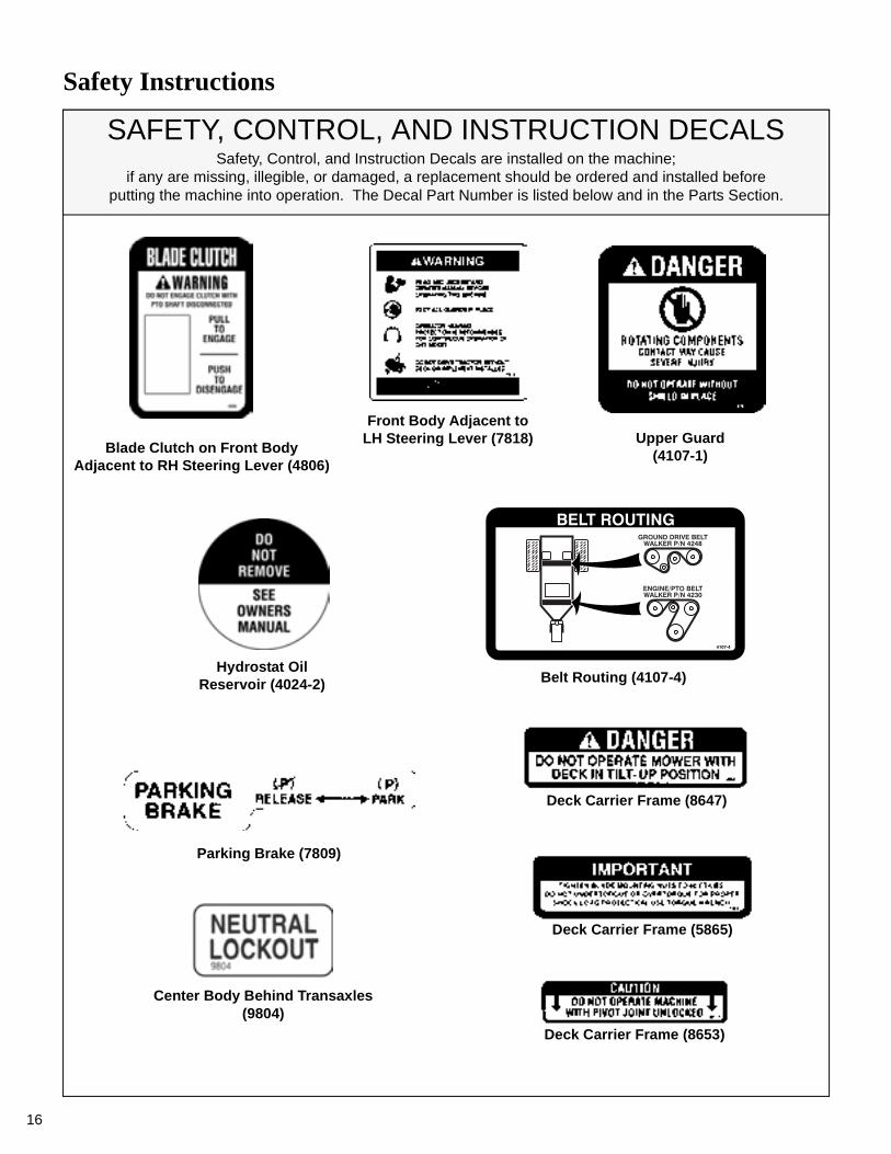
SAFETY, CONTROL, AND INSTRUCTION DECALSSafety, Control, and Instruction Decals are installed on the machine;
if any are missing, illegible, or damaged, a replacement should be ordered and installed beforeputting the machine into operation. The Decal Part Number is listed below and in the Parts Section.
RH Fender (5802-1)LH Fender (5802-2)
Each End of Mower Deck (5808)
SD Deck Discharge Shield (5848)
Deck Gearbox Cover (5807-3)
Rear Body,Above Muffler (5805)
Safety Instructions
16
SAFETY, CONTROL, AND INSTRUCTION DECALSSafety, Control, and Instruction Decals are installed on the machine;
if any are missing, illegible, or damaged, a replacement should be ordered and installed beforeputting the machine into operation. The Decal Part Number is listed below and in the Parts Section.
Parking Brake (7809)
Center Body Behind Transaxles(9804)
Front Body Adjacent toLH Steering Lever (7818) Upper Guard
(4107-1)Blade Clutch on Front BodyAdjacent to RH Steering Lever (4806)
Deck Carrier Frame (8653)
Deck Carrier Frame (5865)
Deck Carrier Frame (8647)
Hydrostat OilReservoir (4024-2) Belt Routing (4107-4)

Assembly Instructions
17
SETUP INSTRUCTIONS
Walker Mowers are shipped partially assembled toour distribution network, and are typically assembledby the selling dealer. For any additional assemblybesides the following, contact your Walker dealer.
Battery Service
The battery is a completely sealed, non serviceablebattery.
IMPORTANT: Make sure battery is securelymounted in the frame. A loose battery may causedamage to the case resulting in acid leakage and se-vere damage to the machine. A hazard may be cre-ated by damage to critical working parts and safetysystems.
Mower Deck Assembly
Deck Caster Wheels Installation
1. Remove the bolt, nut, axle spacer tube, andspacer washers from each deck caster wheelfork.
NOTE: Spacer washers are used only whenthe optional semi-pneumatic deck wheels (8.25x 2.75) are installed.
2. Fit the axle spacer tube through the wheel hub,position the spacer washer on each side of thehub (if used), and fit the assembly into the wheelfork.
3. Insert the 3/8-16 x 4-1/2 in. bolt through thewheel fork with the bolt head to the outside andinstall the 3/8-16 in. Keps nut.
4. Tighten the bolt and nut until the axle spacertube bottoms against the inside of the wheelfork (will not turn) while the wheel and spacerwashers (if used) spin freely without binding.
Deck Caster Wheel Installation
Deck Discharge Shield Installation(Side Discharge Models Only)
Attach the deck side discharge shield by positioningthe shield hinge lug in front of the deck mount andfastening with two 3/8-16 x 1-1/4 in. bolts, 3/8-16ESNA nuts, and 3/8 in. wave spring washers. Thewave washers fit between the two hinging surfaces.Tighten the nuts until the shield moves freely but isnot loose.
Deck Discharge Shield Installation
WARNING
DO NOT operate the machine without thegrass deflector chute attached and in thelowest possible position.
Attach Shield

Assembly Instructions
18
PTO Shaft Guard Installation
Position the shaft guard as shown and mount withtwo 1/4-20 x 1/2 in. bolts.
PTO Shaft Guard Installation
Tilt-Up Roller Wheel Installation
NOTE: A 2-1/2" diameter tilt-up roller wheel(P/N 9772) is required for decks installed on theModel MB tractor.
Mount the two (2) tilt-up roller wheels on the brack-ets on the rear skirt of the deck housing using the P/N 8490 axle bolt, 3/8 in. wave spring washer and3/8-16 in. Whiz locknut. Tighten the axle bolt untilthe wheel rolls freely, but is not loose.
Roller Wheel Installation
Mower Deck Installation on Tractor
Deck Installation
1. Lightly grease each deck support arm (2) on thetractor. Refer to Mower Deck Installation photofor location of deck support arm.
2. Engage the deck carrier frame tube sockets onthe tractor support arms (refer to PTO ShaftGuard Installation photo for socket location).Slide the deck onto the support arms approxi-mately 3 in. (76 mm).
3. Align and connect the splined PTO shaft andsocket halves, as shown in PTO Shaft Connec-tion photo. The PTO shaft has a pilot end to easealignment of shaft; fit shaft end into socket androtate shaft until the splines line up as indicatedby arrows, then slide together.
PTO Shaft Connection
4. Install the hitch pin through the hole on the endof each support arm to lock the deck in place (re-fer to Deck Counterweight Spring Installationphoto). Two (2) hitch pins are included in theowner’s packet of materials.
Mower Deck Installation
Carrier FrameTube Sockets
AttachGuard
Roller Wheels
PTO Connection
Arrows on Shaft and Tube(used to align when sliding together)
Deck SupportArms

Assembly Instructions
19
Deck Counterweight Spring Installation
5. Raise mower body (instead of lifting the front ofdeck) and clip the counterweight springs to thereceptacle on front of body. Lower the body totension the springs. (Refer to Deck Counter-weight Spring Installation photo.)
6. With the counterweight springs connected, theweight on the deck caster wheels should be 15to 25 Ib (6.8 to 11.3 kg). Check this weight by lift-ing on the front of the deck carrier frame. Ifrequired, the spring tension can be adjusted bytightening or loosening the elastic stop nuts lo-cated underneath the lower spring hook. Referto Deck Counterweight Spring Installationphoto.
Hitch PinsLock Deck OnSupport Arms
Counterweight SpringsClip Onto Body
With Body Tilted Up
Spring Tension Adjustment NutLocated Under Lower
Spring Hook (not visible)

Assembly Instructions
20
Deck Leveling
1. Position mower on a smooth, level surface. Setthe cutting height to the highest position - 4 in.(102 mm) - for easy access under the deck tomeasure blade height. Refer to ADJUSTINGCUTTING HEIGHT in Operating Instructions.
NOTE: A block of wood cut 4 in. (102 mm) highis a convenient gauge to measure blade heightabove ground during the leveling process.
2. Check the side-to-side level. Rotate each bladesideways and measure the distance from bladetip to ground on each side. If measurementsvary more than 1/8 in. (3 mm), add a washershim under the deck support pins on the low sideto level the deck.
3. Check the front-to-rear level. Rotate the bladesto point forward. Measure the distance fromblade tip to ground on the front and rear. Therear of the blade should be 1/8 to 1/4 in. (3 to 6mm) higher than the front of the blade; shim therear (or front) deck support pins equally toachieve at least 1/8 in. (3 mm) difference.
NOTE: The mower deck and support frameare jig welded; within normal tolerances, very lit-tle, if any, shimming should be required to levelthe deck. Tire pressure will influence the level-ness of the deck. Check the tire pressure as apossible cause of the deck not being level.
WARNING
The machine must be shut off during this procedure.
4 in. (102 mm)Wood Block
Should not vary more than 1/8 in. (3 mm)
side-to-side
Should be 1/8 in. (3 mm) to 1/4 in. (6 mm) higher at the rear of the blade
4 in. (102 mm)Wood Block
Deck Leveling

Assembly Instructions
PREOPERATING CHECKLIST
Before operating the mower for the first time, and asa routine before daily operations, it is important tomake sure the mower is properly prepared and readyfor operation. The following is a list of items to bechecked. (For a mower with frequent operation,some of these items will not need to be checked everyday, but the operator should be aware of the conditionof each.)
Body Rod in Engaged Position
Body Rod in Stowed Position
CHECK BODY ROD IN STOWED POSITION
Check that body rod is secured in the stowed positionbefore lowering body. Refer to Body Rod in StowedPosition photo.
For proper fuel and lubricants refer to Specifications.
FILL FUEL TANK
Fill the fuel tank using clean, fresh, automotive gradeunleaded gasoline (85 octane rating minimum).
Body Rod
Body Rod
21

Assembly Instructions
22
IMPORTANT: DO NOT permit dirt or other foreignmatter to enter the fuel tank. Wipe dirt from aroundthe filler cap before removing. Use a clean fuel stor-age container and funnel.
IMPORTANT: DO NOT mix oil with gasoline.Always use fresh, automotive grade unleaded gas-oline. DO NOT use premium, white, or high-testgasoline. DO NOT use additives, such as carburetorcleaners, deicers, or moisture removing agents. DONOT use gasoline blended with methyl alcohol.
CHECK ENGINE CRANKCASE OIL LEVEL
Check the engine crankcase oil level before use andafter each 8 hours of continuous operation. Referto LUBRICATION for Checking Engine CrankcaseOil Level in Maintenance Instructions.
CHECK AND SERVICE ENGINE AIR CLEAN-ER SYSTEM
• Check condition, cleanliness, and security of thecomplete air filter element (clean air filter every100 hours). For detailed procedures, refer toCLEANING the Air Cleaner System in Mainte-nance Instructions.
CHECK ENGINE COOLING SYSTEM
Check that the engine cooling air intake screen is freeof obstruction by grass clippings or debris and cleanif required. Also, cylinder head cooling fins should beinspected and cleaned if any build-up of debris isnoted. Contact your Walker Dealer to perform thisprocedure.
CHECK SECURITY OF DRIVE TIRE MOUNT-ING NUTS
The eight (8) Drive Tire mounting nuts should eachbe torqued to 75-85 ft-lbs. (101.7-115.2 N⋅m).
INSPECT TWO (2) DRIVE BELTS
Engine/PTO and Ground Drive.
CHECK HYDROSTATIC TRANSAXLE OILLEVEL
Refer to LUBRICATION for Transaxle Lubricationin Maintenance Instructions.
CHECK TIRE PRESSURE
Deck Caster Wheel = 20 PSI (137 kPa)Drive = 15 PSI (103 kPa)Rear = 20 PSI (137 kPa)
CHECK AND CLEAN GRASS BUILDUPUNDERNEATH MOWER DECK
Refer to CLEANING in Maintenance Instructions fordeck cleaning information.
The tilt-up deck can be secured in the raised positionby unlocking the deck lock levers on each side of thecarrier frame and inserting the deck hook into the tilt-up latch on the tractor body. Before operating thetractor, make sure to re-engage the deck lock leversafter lowering the deck to the normal operating posi-tion.
DANGER
Handle gasoline with care. Gasoline is high-ly flammable and its vapors are explosive.Use safe refueling procedures:
• DO NOT fill fuel tank with the engine run-ning.
• If the engine is hot, allow to cool beforerefueling.
• Use an approved fuel container.
• Fuel the mower outdoors.
• DO NOT smoke while refueling.
• Avoid spilling fuel; use a funnel or spout.
• DO NOT overfill the fuel tank; fill up toabout 1 in. (25 mm) below the top of tank.
DANGER
Never operate cutter blades with deck inraised position because it is hazardous.
Assembly Instructions
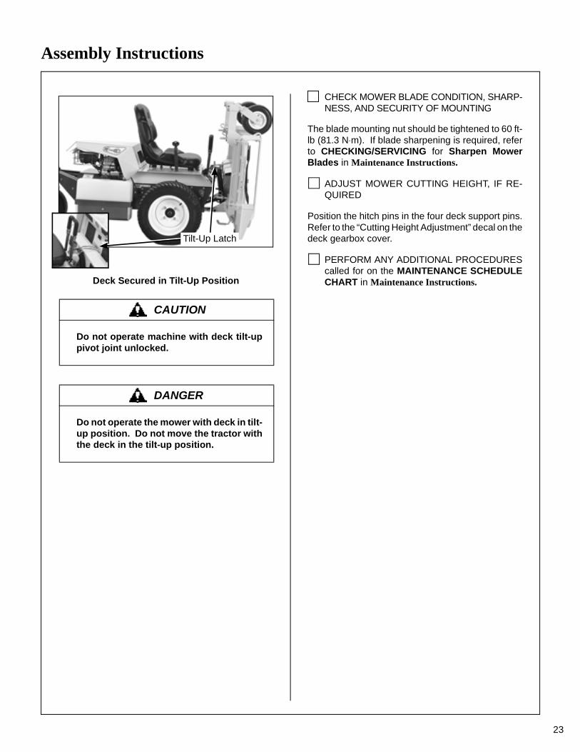
Deck Secured in Tilt-Up Position
CHECK MOWER BLADE CONDITION, SHARP-NESS, AND SECURITY OF MOUNTING
The blade mounting nut should be tightened to 60 ft-lb (81.3 N⋅m). If blade sharpening is required, referto CHECKING/SERVICING for Sharpen MowerBlades in Maintenance Instructions.
ADJUST MOWER CUTTING HEIGHT, IF RE-QUIRED
Position the hitch pins in the four deck support pins.Refer to the “Cutting Height Adjustment” decal on thedeck gearbox cover.
PERFORM ANY ADDITIONAL PROCEDUREScalled for on the MAINTENANCE SCHEDULECHART in Maintenance Instructions.
CAUTION
Do not operate machine with deck tilt-uppivot joint unlocked.
DANGER
Do not operate the mower with deck in tilt-up position. Do not move the tractor withthe deck in the tilt-up position.
Tilt-Up Latch
23

Operating Instructions
24
CONTROL IDENTIFICATION, LOCATION, AND FUNCTION
Ignition Switch
The ignition switch is located on the right front of thebody and is used to start and stop the engine. Theswitch has three positions: “O” is the OFF position,RUN is the position the key returns to after starting,and “S” is the START position. When starting theengine, turn the key clockwise to the “S” position. Donot hold the key in the “S” position longer than 10
seconds. If the engine does not start, return the keyto the “O” position for at least 60 seconds beforemaking a restart attempt. Prolonged cranking candamage the starter motor and shorten battery life.Release the key when the engine starts, and it willreturn to the RUN position. To stop the engine, rotatethe key counterclockwise to the “O” position.
Ignition Switch
CAUTION
Before operating the mower, become fa-miliar with the location and function of alloperator controls. Knowing the location,function, and operation of these controlsis important for safe and efficient opera-tion of the mower.
START
ONOFF
Operating Controls
SteeringLevers
Throttle
Blade Clutch(PTO)
IgnitionSwitch
Choke(not visible)
Parking Brake
Forward SpeedControl (FSC)
Hourmeter
BodyLatch

Operating Instructions
25
Engine Choke
The choke control lever (black knob) is located onthe left side of the seat. To start a cold engine, movethe choke control forward to the ON position. Afterengine starts, move choke control toward the OFFposition, keeping enough choke to allow the engineto run smoothly as it warms up. As soon as possible,move the choke to the OFF position. A warm enginerequires little or no choke for starting.
IMPORTANT: Make sure the choke is in the OFFposition during normal engine operation; runningwith the choke in the ON position CAN damage theengine.
Engine Throttle
The throttle control lever (red knob) is located on theleft side of the seat and is used to control enginespeed. Moving the lever forward toward the FASTposition increases engine speed; moving it back-ward toward the IDLE position decreases enginespeed.
Choke and Throttle Location
Forward Speed Control (FSC)
Forward Speed Control (FSC) has two functions:One is to set forward travel speed, and the other isto establish the NEUTRAL-PARK position. Whenthe FSC lever is moved into the FORWARD position,a friction lock holds any forward speed setting from0 to 7 mph (0 to 11.3 km/h). The ground speed is pro-portional to the lever position; the further the lever isadvanced forward, the faster the tractor moves. It isnot necessary to hold the FSC in position since thefriction lock maintains the selected lever position.Pulling back on the steering levers overrides theFSC setting and slows or stops forward travel.Releasing the steering levers allows the tractor toresume forward travel at the speed set by the FSClever. To stop and park the machine, the FSC leveris moved backward to the NEUTRAL-PARKposition.
Steering Levers
Each drive wheel is controlled by its own indepen-dent steering lever, for both steering function andFORWARD/REVERSE motion. The FSC lever setsthe maximum forward speed, and also sets the for-ward position of the steering levers. The steeringlevers operate only with a backward pulling move-ment of the lever, which causes the drive wheel forthat lever to first slow down, stop, and then reversewith a full backward lever stroke. The levers arereleased to the FORWARD position for “straight-ahead” ground travel.
NOTE: Pushing forward on the steering levers willnot cause any change in tractor motion - there will beno steering lever reaction and there will be nomachine damage.
PTO Switch
The PTO toggle switch is located on the RH front ofthe body and has two positions: ON (ENGAGE) andOFF (DISENGAGE) - positioning switch "ON" acti-vates the electromagnetic blade drive clutch whilethe blade brake is applied when the switch is movedto "OFF".
ChokeThrottle

Operating Instructions
26
Parking Brake
The parking brake functions by locking a detent arminto the transaxle outer control gear teeth. Movingthe lever FORWARD engages the parking brake;moving the lever BACKWARD releases the brake.
IMPORTANT: Stop the tractor completely beforeengaging the parking brake. The parking brake usesa positive mechanical lock similar to the PARK posi-tion on an automotive automatic transmission. If thetractor is moving when the brake is engaged, it willresult in sudden stoppage and possible internaldamage to the transaxle.
NOTE: If pressure on the parking brake pin (e.g.parked on a hill) makes it impossible to release theparking brake with the parking brake lever, move themower gently forward or backward to allow the brakedetent to set into the teeth.
Transaxle Lockout Rods
The transaxle lockout rods disengage the transax-les. By lifting the rods up and locking them into placewith the shoulder on the rod in the chassis notch, thetransaxles are released to permit freewheeling. Byreleasing the rods and recessing them back towardthe chassis, the transaxles are engaged for normaloperation. The transaxle rods in the LOCKOUTposition are used to enable moving the machinewithout the engine running (e.g., for service). Referto TRANSAXLE LOCKOUTS in this section foroperating instructions.
NOTE: The transaxle lockout rods ends should becompletely retracted against the body, otherwiseoperation of the transaxle may be erratic.
Hydro Lockout Rod Location
Hourmeter
The hourmeter, which is located on the right front ofthe body, displays operating time accumulatedwhile the ignition switch is in the ON position.
The hourmeter provides maintenance remindersafter certain hours of operation. The hourmeterscreen will start flashing the reminder one hour priorto the recommended interval and will continue untilone hour after the recommended interval (twohours). The hourmeter does not have a manualreset function.
* These intervals reflect the actual time that thereminder will flash (one hour prior to and onehour after the recommended interval).
** This reminder is only used one time.
*** In normal operating conditions, oil changes in100-hour intervals are acceptable. Walker andthe engine manufacturers recommend engineoil changes every 50 hours in extremely dirtyor dusty conditions or for units with less than100 hours annual use.
NOTE: The blinking hour glass on the displaymeans that the meter is operating properly.
Hourmeter
Hydro LockoutRods
Procedure Interval* Reminder
Oil Change (Break-In)** 4-6 Hours
CHG
���
Lubricate and Check Levels
24-26 Hours ����
Oil Change 49-51 Hours***CHG
���

Operating Instructions
27
THROTTLE
BLADE CLUTCH(PTO)
PARKINGBRAKE
LEFT WHEELSTEERING LEVER
Forward Position(No Control Change)
RIGHT WHEELSTEERING LEVER
FORWARD SPEEDCONTROL LEVER (FSC)
Full ForwardGround Speed
Position
IntermediateGround Speed
Position
Neutral-ParkPosition
IdlePosition
ON Position
OFF Position
CHOKE
FastThrottlePosition
Operating Controls (Top View from Drivers Point of View)
The Forward Speed Control also Establishes the Neutral-Park Position of the Steering Levers
Neutral-ParkPosition
Reverse DriveWheel Motion
Position
EngagedPosition
DisengagedPosition
DisengagedPosition
EngagedPosition
Operating Instructions
28
STARTING THE ENGINE
1. Before attempting to start the engine, makesure the operator is in the seat, the ForwardSpeed Control is in NEUTRAL-PARK position,and the blade clutch and parking brake areDISENGAGED.
NOTE: Release parking brake to prevent extraload on the starter if the transmission neutral isslightly out of adjustment.
2. Move the choke lever to the ON position and
move the throttle 1/4 to 1/2 open (toward FAST).Turn the ignition switch to the START position tostart the engine. Release the key to RUN posi-tion as soon as the engine starts.
NOTE: The choke may not be required if theengine is warm.
IMPORTANT: DO NOT crank the engine con-tinuously for more than 10 seconds at a time. Ifthe engine does not start, turn the key to theOFF position and allow a 60 second cool-downperiod between starting attempts. Failure to fol-low these guidelines can damage the startermotor and shorten battery life.
3. After the engine starts, gradually move thechoke to the OFF position, keeping enoughchoke on to allow the engine to run smoothly asit warms up. As soon as possible, move thechoke to the OFF position.
IMPORTANT: Make sure the choke is in theOFF position during normal engine operation;running with the choke in the ON position CANdamage the engine.
ADJUSTING GROUND SPEED AND STEERING
CAUTION
Before operating the mower, read and un-derstand all Safety Instructions and Operat-ing Instructions.
WARNING
NEVER run the engine in an enclosed orpoorly ventilated area. Engine exhaustcontains carbon monoxide, an odorlessand deadly gas.
CAUTION
A safety interlock switch system PRE-VENTS CRANKING the engine with eitherthe Forward Speed Control or the bladeclutch (PTO) out of neutral. If the enginecranks otherwise, the safety system is notworking and should be repaired or adjust-ed before operating the mower. DO NOTdisconnect safety switches; they are forthe operator’s protection.
CAUTION
Learn to START, STOP, and MANEUVERthe mower in a large, open area.
If the operator has not operated a machinewith LEVER STEERING OR DUAL TRAN-SAXLES, steering and ground operationshould be learned and practiced until theoperator is completely comfortable han-dling the machine BEFORE ATTEMPTINGTO MOW.
DANGER
Keep feet on footrest at all times when themachine is moving.

Operating Instructions
1. Move the FSC out of NEUTRAL-PARK positionto the desired forward speed. DO NOT hold for-ward on steering levers. It is not necessary tohold the FSC lever in position since a frictionlock maintains the selected lever position (andforward travel speed).
NOTE: This is exactly the same procedureused to normally stop and park the machine.
NOTE: If the FSC lever will not stay in theselected position, the friction lock needs to beadjusted. Contact your Walker Dealer.
2. Steer by pulling the lever on the side of desireddirection of turn, e.g., pull the LH lever to turnleft. To minimize the possibility of overcontrol,use only one hand on both steering levers.
Correct Operator Hand Position on the Controls
Beginning Recommendations are:
♦ Learn operation of the mower in an openarea away from buildings, fences, and ob-structions. Learn operation on flat groundBEFORE operating on slopes.
♦ Start maneuvering the mower with SLOWengine speed and SLOW Forward SpeedControl setting until familiar with all operat-ing characteristics.
♦ Remember it is not necessary to hold thesteering levers forward (a unique Walkerfeature); always PULL on the levers forsteering or for reverse motion of the mower.
♦ Learn to operate the mower with your lefthand on the steering levers and right hand onForward Speed Control. The use of twohands on the steering levers tends to causeovercontrol.
♦ Learn to operate the steering levers withsmooth action. Jerky movements are hardon the transmission and lawn. For sharpturns, do not allow the inside wheel to stopand twist on the grass. Pull the steering le-ver controlling the inside wheel into reversefor a smooth “rolling” turn (one wheel roll-ing forward while the other rolls backward).
♦ Practice maneuvering the mower untilyou can make it go exactly where you areaiming.
♦ Remember, for an emergency stop, or incase of loss of control, machine movementcan always be stopped quickly by pullingthe Forward Speed Control into the NEU-TRAL-PARK position.
WARNING
In case either of the transmission drivebelts break during operation, and if themachine is on a slope, the machine willfreewheel down the slope. To maintaincontrol, immediately (1) Release thesteering levers and simultaneously (2)Move the FSC to the NEUTRAL-PARKposition. When the machine is stoppedor moving slowly, engage the parkingbrake.
Pull SteeringLevers withLeft Hand
Forward Speed Control(FSC)
Keep Feet on Footrestwhen Moving
29

Operating Instructions
30
3. Reverse direction of the mower by pulling bothlevers backward.
NOTE: Smooth action on the steering leverswill produce smooth mower operation. Remem-ber to keep the engine and ground speed slowuntil learning the control response.
4. The FSC may be adjusted forward for fasterground speed and backward for slower groundspeed. When mowing, ground speed should beadjusted to match the load on the cutter blades,i.e., as the engine pulls down in heavy cutting,pull back on the FSC lever to reduce groundspeed. Adjusting ground speed helps maintaina balance between engine power and bladespeed for high-quality cutting action.
5. Stop ground travel by pulling both steeringlevers backward to the NEUTRAL-PARK posi-tion (tractor not moving) and then moving theFSC lever to the NEUTRAL-PARK position.
NOTE: If the tractor creeps forward or back-ward with the FSC lever in the NEUTRAL-PARKposition, the transmission control needs to beadjusted. Contact your Walker Dealer.
ENGAGING THE MOWER
1. Set the engine throttle at about 1/2 speed. DONOT attempt to engage the blade clutch athigh engine speeds. This will drastically short-en drive belt and clutch life. Use only moderateengine speed when engaging the blade clutch.
2. Pull up the blade clutch toggle switch to engagethe mower blades.
IMPORTANT: DO NOT engage the blade clutchwhen transporting the mower across drives, side-walks, loose materials, etc. DO NOT engage theblade clutch with the PTO shaft disconnected(the mower deck removed from tractor).
Blade Clutch Engaged
Blade Clutch Disengaged
CAUTION
A safety interlock switch (seat switch) willcause the engine to stop if the bladeclutch is engaged and the operator is notin the seat. The function of this switchshould be checked by the operator rais-ing off the seat and engaging the bladeclutch; the engine should stop. If theswitch is not working, it should be re-paired or replaced before operating themower. DO NOT disconnect the safetyswitches; they are for the operator’s pro-tection.
CAUTION
If the cutting blades strike a stationaryobject while mowing, stop the mower im-mediately, disconnect the spark plugwires, lift the deck, and inspect the deckand blades thoroughly for damage. Makesure that the blade timing has not beendisturbed (the blades should be at 90 de-grees to each other). Refer to REPLAC-ING/REPAIRING the Blade Overload ShearBolts in Maintenance Instructions if bladesare out of time. Also, make sure the bladeretaining nuts are torqued to 60 ft-lb (81.3N⋅m).

Operating Instructions
31
STOPPING THE MACHINE
1. Slow the engine to idle; put the throttle in theIDLE position.
2. Pull the steering levers to the NEUTRAL-PARKposition and then move the FSC lever backwardto the NEUTRAL-PARK position.
3. Disengage the blade clutch.
IMPORTANT: DO NOT disengage the bladeclutch with high engine speed (above 1/2throttle) since the brake action on the blade drivewill cause premature wear of the Engine/PTOBelt and electric clutch/brake.
4. Turn the ignition switch OFF.
5. Engage the parking brake.
IMPORTANT: The transaxles lock to prevent themower from rolling freely with the enginestopped. However, if the mower is parked on aslope, it is necessary to ENGAGE the parkingBRAKE to prevent the mower from creeping.This is due to a small amount of slippage in thetransaxles, especially when transmission fluidis warm.
ADJUSTING CUTTING HEIGHT
Cutting height is adjusted by positioning the fourretainer hitch pins in a series of seven verticalholes on the deck support pins. Lift handles havebeen provided on each end of the deck to assist inraising the deck while positioning the hitch pins. Cut-ting heights range from 1 in. (25 mm) [top holes] to4 in. (102 mm) [bottom holes] in 1/2 in. (13 mm)increments.
Cutting Height Adjustment
WARNING
A brake stops the cutter blades from free-wheeling within five (5) seconds after dis-engaging the clutch. If the brake systemmalfunctions and the blades do not stopwithin five (5) seconds, the brake shouldbe repaired or replaced before operatingthe mower. Contact your Walker Dealer.
WARNING
Remove the key from the ignition switchwhen leaving the mower unattended. Thiswill prevent children and inexperiencedoperators from starting the engine.
WARNING
The engine must be stopped before ad-justing cutting height. Disengage theblade clutch (PTO), stop the engine, andremove the ignition key. Wait for all move-ment to stop before getting off the seat.
Lift Handle
Deck Support Pin
Hitch Pin

Operating Instructions
32
TRANSAXLE LOCKOUTS
IMPORTANT: DO NOT TOW this mower with thetransmission lockout engaged. Towing can produceexcessive internal pressure and damage thetransaxle.
To move the mower with the engine NOT running(dead battery, maintenance, etc.), the transaxles areunlocked (released).
1. Raise the body.
2. Pull up the transaxle lockout rods on both theRH and LH transaxles and secure into place byshouldering both rods in the chassis notch area.
3. The mower will “freewheel” with the rods in theLOCKOUT position. The levers must be in thehighest position to completely unlock thetransmissions.
Hydro Lockout Rod - Freewheel Position
4. After moving the mower, release the rods, plac-ing them in the normal OPERATING position.The transmission rod ends should be com-pletely retracted against the chassis, otherwiseoperation of the transmission maybe erratic.
Hydro Lockout Rod - Normal Operating Position
RECOMMENDATIONS FOR MOWING
IMPORTANT: Operate the engine at full speedwhen mowing, to allow the engine to produce fullhorsepower and to increase efficiency of the enginecooling system.
• Keep the mower deck and discharge chute clean.
• Mow with sharp blades. A dull blade tears thegrass (resulting in poor lawn appearance) and usesextra power (slowing the mowing speed).
• It is preferable to cut grass when it is dry and nottoo tall. Mow frequently and do not cut grass tooshort. (For best appearance, cut off 1/3 or less ofexisting grass height.)
• When mowing, operate the engine at or near fullthrottle for the best cutting action. Mowing with alower engine RPM causes the mowing blade to notcut clean and tear the grass. The engine isdesigned to be operated at full speed.
• When mowing in adverse conditions (tall and/orwet grass), mow the grass twice. Raise the mowerto the highest setting - 4 in. (102 mm) - for the firstpass and then make a second pass cutting to thedesired height.
• Use a slow setting on the FSC for trimmingoperations.
Hydro Lockout Rod
Hydro Lockout Rod

Operating Instructions
33
• Make sure the mower is leveled properly for asmooth cut. Refer to Deck Leveling in AssemblyInstructions.
• Use an alternating stripe mowing pattern forbest appearance and vary the direction of the stripeeach time the grass is mowed to avoid wear patternsin the grass.
• Avoid damage to the grass by slipping and skid-ding of the drive tires. Use smooth control move-ments of the steering levers since the transaxles are“power boosted controls” and jerking the levers caneasily slip the tires. For sharp turns, do not allow theinside wheel to stop and twist on grass; pull insidesteering lever into reverse for a smooth “rolling” turn(one wheel rolling forward while the other rolls back-ward).
• When using a side discharge mower deck, theside discharge shield must not be removed andmust be kept in the lowest possible position todeflect grass clippings and thrown objects down-ward. Orient the side discharge away from side-walks or streets to minimize cleanup of clippings.When mowing close to obstacles, orient the side dis-charge away from obstacles to reduce the chance ofdamage to property by thrown objects.
Side Discharge Shield in Lowest Position
• When operating on a slope, reduce speed anduse caution to start, stop, and maneuver. Avoidsharp turns or sudden changes in direction. Themaximum recommended side slope operatingangle is 20 degrees or 33% grade.
Maximum Recommended Side Slope
RECOMMENDATIONS FOR TILT-UP DECK OPERATION/TRANSPORT
To avoid potential deck and/or tractor damage whileusing the tilt-up deck, the following recommenda-tions are offered:
• Do not move the tractor with the deck in the tilt-up position since both the roller wheels (on the backof the deck) may be damaged by moving the tractor.The tilt-up configuration should only be used whenthe tractor is parked.
• The tractor body should never be tilted for-ward with the deck in the tilt-up position. This cancause the deck to unhook from the tractor and fallwith considerable force, potentially causing deck ortractor damage and/or bodily injury.
• When transporting a tractor with the deck in thetilt-up position (on a truck or trailer), the deckshould be secured to the vehicle with a strap orrope (stop vertical movement). This will prevent thedeck from bouncing on the rear roller wheels (caus-ing breakage). This will also prevent the deck fromunhooking from the tractor and falling, potentiallycausing deck or tractor damage. Damage to otheritems parked in front of the deck may also occur.
DischargeShield
Maximum RecommendedSide Slope - Do Not Operate
on Steep Slopes
60 in.
22 in.20°

Maintenance Instructions
34
MAINTENANCE SCHEDULE CHART - RECOMMENDED SERVICE INTERVALS - MODEL MB
Service Item Daily25
Hours50
Hours100
Hours250
Hours YearlyRef.Page
Check Engine Crankcase Oil Level x 36
Check/Clean Engine Air Cooling System* x 41
Clean Grass Buildup Under Deck x 42
Service Mower Blades x 44
Check Security of Air Cleaner System x 44
Lubricate Grease Fittings and Oil Points* x 37
Check Transaxle Fluid x 40
Check Tire Pressure x 44
Check Drive Belts (Engine, PTO, Ground Drive) x 45
Check PTO and Deck Gearbox Oil Seals x 45
Inspect Air Filter Paper Element* x 42
Clean and Re-Oil Air Filter Foam Element x 42
Change Engine Crankcase Oil** x 36
Change Engine Oil Filter x 36
Check Security of Drive TireMounting Nuts (75-85 ft-lbs.) x 22
Clean Transaxle Cooling Fins x 43
Change Transaxle Oil and Filter x 40
Replace Fuel Filter x 49
∗ More often in extremely dusty or dirty conditions(see notes about air cleaner element underIMPORTANT TIPS FOR CARE OF BRIGGS & STRATTON ENGINE)
∗∗ Change engine oil and filter after first 8 hours of operation of a new engine (break-in period)
CAUTION
When performing maintenance with themower body raised, a safety prop shouldbe installed from back of body to chassisframe (fail-safe protection in case of fail-ure of body lift support).
CAUTION
Maintenance procedures requiring special training ortools should be performed by a trained technician.

Maintenance Instructions BRIGGS & STRATTON TIPS
35
IMPORTANT TIPS FOR CARE OF THEBRIGGS & STRATTON ENGINE
Fuel System
• Fuel must be clean - free from water, dirt, and or-ganic material.
• Clean the fuel filter on a regular basis and whencontamination is suspected or found in the fuel.
Starting
• Start engine with the throttle advanced off idle(1/4 to 1/2 throttle). This will aid starting, especiallyin cold weather.
• Keep the battery fully charged.
• Match crankcase oil viscosity to the ambient tem-perature, allowing the engine to crank faster andstart easier.
• Allow engine to run at idle for a few seconds be-fore stopping engine to avoid run-on or backfiring.
Cooling System
• Keep engine air intake screen and cylinder headfins free of grass clippings, chaff, and dirt. Inspectintake screen and cooling fins for cleanliness anddamage.
• Operate the engine at full speed when mowing.This will allow the engine to produce full horsepowerand move more cooling air through the engine cool-ing fins.
Air Cleaner
• Use only Briggs & Stratton air cleaner elements.Aftermarket elements may not seal in the air cleanerhousing, allowing dirt to enter the engine. Also, af-termarket filters often skimp on the filtration mediaand require more frequent cleaning and replace-ment.
• DO NOT overservice or frequently “disturb” theair filter. A dirty air filter actually cleans better thana new one. Changing and cleaning the filter too of-ten can actually reduce filter efficiency and increasethe opportunity for traces of dust to enter the engine.Wait until the element really needs servicing as indi-cated by the loss of engine power.
• When the air filter element is removed or re-placed, make sure all dust is cleaned out of the aircleaner body. Use a damp cloth and wipe the inte-rior of the air cleaner body clean (a little dirt left herewill be sucked into the engine and reduce enginelife). When the filter is reinstalled, make sure the el-ement is held tight and straight in the air cleanerbody for proper seating and sealing.
Oil
• Single viscosity or multi-viscosity oils may beused with the viscosity matching ambient tempera-tures for the engine operating conditions. This willaid starting in cold weather and assure proper lu-brication in hot weather.
• Use only Briggs & Stratton oil filters. Aftermarketfilters may not seal properly and/or have the in-correct pressure relief valve for proper lubrication.

Maintenance Instructions LUBRICATION
36
LUBRICATION
Proper lubrication is an important maintenance pro-cedure. It reduces wear and makes the machinequieter and easier to operate.
Engine Oil
Engine Break-In Oil
No special break-in oil is required. The engine is ser-viced with 10W-30, Service Class SG oil from thefactory. The oil should be changed after the initialengine break-in period of 5-8 hours. Thereafter,change oil after every 50 hours of operation.
Checking Engine Crankcase Oil Level
Check the engine crankcase oil level before use andafter each 8 hours of continuous operation.
IMPORTANT: The importance of checking andmaintaining the proper crankcase oil level cannot beoveremphasized. Check the oil level BEFOREEACH USE.
1. Park the mower on a level surface with theengine stopped. Also, make sure the engine iscool and oil has had time to drain into the sump[allow at least five (5) minutes after stoppingthe engine].
IMPORTANT: NEVER check or add oil with theengine running.
2. Before removing the dipstick, clean the areaaround the dipstick to keep any dirt or debris outof the engine.
3. Remove the dipstick, wipe off with a clean rag,then reinsert the dipstick into the tube and pressall the way down.
4. Remove the dipstick again and check the oillevel on the dipstick. The oil level should bewithin the “Operating Range” on the dipstick(between the LOW mark and the FULL mark).
IMPORTANT: DO NOT operate engine withoutsufficient oil supply in the crankcase. DO NOToperate with oil level below the LOW mark orabove the FULL mark on the dipstick.
Dipstick Operating Range
5. If additional oil is needed, refer to Specificationsfor proper crankcase lubricant. Fill to the FULLmark.
IMPORTANT: DO NOT overfill crankcase [oilabove FULL level] as this CAN result in engineoverheating, loss of power, and possibleengine damage.
Changing Engine Crankcase Oil/Oil Filter
Change the engine crankcase oil after every 50hours of operation and the oil filter after every 100hours of operation as follows:
1. Park the mower on a level surface with theengine stopped. The engine oil should bewarm before draining. If not warm from opera-tion, start the engine and run a few minutes towarm the oil.
2. Before removing the dipstick, clean the areaaround it to keep any dirt or debris out of theengine.
WARNING
DO NOT attempt to lubricate the machinewith the engine running. Disengage thePTO clutch, shut off the machine, and re-move the ignition key.
{LOWMark
FULLMark
OperatingRange

Maintenance Instructions LUBRICATION
37
3. Remove the dipstick and oil drain plug, and drainoil into a suitable container. Be sure to allowample time for complete drainage.
4. Before removing the oil filter, clean the areaaround the filter to keep dirt and debris out of theengine.
5. Remove the old oil filter and wipe off the filtermounting surface on the engine.
Dipstick and Oil Fill(view from above left side of tractor)
Oil Drain and Oil Filter Locations(view from above right side of tractor)
6. Apply a thin coating of new oil to the rubber gas-ket on the replacement oil filter.
IMPORTANT: Use ONLY oil filters from theengine manufacturer. Aftermarket oil filters maynot seal properly and/or may not have the cor-rect pressure relief valve for proper lubrication.
7. Install the new oil filter on the engine. Turn theoil filter clockwise until the rubber gasket con-tacts the sealing surface, then tighten the filteran additional 1/2 to 3/4 turn.
8. Reinstall the drain plug.
9. Fill the crankcase with new, clean oil. Use onlycrankcase lubricants recommended by theengine manufacturer. Refer to Specifications inthis manual or the engine owner’s manual. Usethe recommended oil viscosity for the expectedambient temperature. Oil with the correct vis-cosity will aid starting in cold weather and assureproper lubrication in hot weather. Fill to FULLmark on the dipstick; crankcase capacity is 1.5quarts (1.4 liters) when changing oil and filter.
IMPORTANT: Check the dipstick reading be-fore pouring in the last 1/2 pint of oil and fill onlyto the FULL mark. The oil level should never beover the FULL mark on the dipstick; overfillingcan result in engine overheating and loss ofpower.
10. Start the engine and check for oil leaks aroundthe oil filter. Stop the engine, recheck the oil lev-el, and add oil if necessary. (When the engineis first operated with a new oil filter, the oil levelwill drop slightly as the filter is filled with oil.)
Grease Fitting and Oil Point Lubrication
Lubricate the grease fittings and oil points afterevery 25 hours of operation. Lubricate more oftenwhen operating in dusty or dirty conditions. UseSAE general purpose lithium or molybdenum basegrease for grease fittings and light machine oil (SAE10) to lubricate oil points. Lubricate the locationsshown in the Chassis and Deck LubricationPoints illustration.
NOTE: PTO universal joints (on the deck and trac-tor) require routine lubrication after every 8 hours ofrunning time.
NOTE: The pillowblock bearings on the PTO driveshaft are a sealed, relubricatable-type bearing.Grease lightly once per year using care to notover-lubricate and damage the seals.
Oil Fill
Dipstick
Oil Drain
Oil Filter

Maintenance Instructions LUBRICATION
38
Ident Lubrication No.No. Location Type Places
Ident Lubrication No.No. Location Type Places
� ���������� ��������������� ���� �� ���������� ����������� ���� �� ���������������� ���� � ��!�������������� ���� �" #�������$�����%�&��'�(��) ������ �* �����%+,,����'�(�%����� ���� �- ������'�(��)������.#,����� ���� / %��������0���������� ���� �1 �����������2������� ��� ��3 ����.��.������+,���� ���� �
4�����%��!��'��5�� #�������$������+���'�(��) ������ ��� �����%+,,����'�(������ ���� ��� 6)!���7!����'�(������ ���� �� ����������������� ��� ��" �%��0���������� ���� ��* ��!)�0��� ��� ��- ������������0���� ��� ��/ �������������������8�! ��� ��1 ������������������������ ���� �
�3 �����9��������������������%�&� ����Δ ��� ����������������������8�! ��� ��� 8������:����������� ������ ��� ������������������� ��� �� ���������������������� ��� �
� �����������,��(�����)��+������!��!����!���;+�����������!+��!��+��������<��������������+�!����������!����)9��������������������!<
�� ���������)�������4/5���+�<
��� 2�&��������������������!����,�� �*<
Δ %���!�����+��������.�),���������������������)������,���)��������� �������������������9�������!(��!<
���� �%� ������.#,������ �� ��9�� &��� ��&������<� ��������������� 0+��������� ������� ��&��� ��� ����� ���� ���������������� �� ������ ��������

Maintenance Instructions LUBRICATION
39
3
4
5
7
7
8
9
10
13
16
17
18
6
1
2
4
767
9
1218 & 23
21 & 24
22
20
19
15
1 2
11
12
14
21
20
Chassis and Deck Lubrication Points

Maintenance Instructions LUBRICATION
40
Mower Deck Gearbox Lubrication
The mower deck gearboxes (tee gearbox and bladedrive gearboxes) are connected as a unitizedassembly, and oil flows freely between them. Thegearboxes are permanently lubricated (oil filled) andsealed requiring no scheduled lubrication. However,the gearbox oil seals should be checked every 25hours for indication of an oil leak; particularly thelower seals on the blade drive gearboxes should beinspected, since they operate in a dirty environment.If an oil leak is noted, replace the oil seal and relu-bricate the gearbox assembly as follows:
1. Remove gearbox cover (footrest). Deck orien-tation should be the normal operating position.
Mower Deck Gearboxes(shown with gearbox cover removed for clarity)
2. Clean the area around the individual gearboxcover plates to prevent contaminants fromentering the gearcase.
3. Remove the screws securing the cover plateson the blade drive gearboxes.
4. Check the level of lubricant in the gearboxes. Ifthe lubricant is low, add SAE E.P. (ExtremePressure) 90W oil until the oil level is up to (sub-merges) the horizontal shaft in the gearbox(shaft parallel to cover plate).
NOTE: In case the gearboxes are completelydrained of oil, approximately 5 fl. oz. (15 cl) of oilper gearbox is required to refill the gear driveassembly.
NOTE: Since the gearboxes are connected asa unit by connector tubes, it is necessary to addoil slowly. Allow a few minutes after adding oilfor the oil to flow throughout the assembly andthe oil level to stabilize before reassembly.
IMPORTANT: DO NOT overfill the deck gear-boxes. The gearbox assembly is not vented,and overfilling with oil will cause excessive pres-sure and result in oil leaks.
5. Check condition of the cover gasket and replaceif worn or damaged. Reinstall gearbox coverplates; torque screws to 24 in-lb (2.7 N·m).
Transaxle Lubrication
• The transaxle oil lubrication is SAE 20W-50 (APIService Class SL or higher) engine oil.
• Inspect both transaxle cases and hoses after ev-ery 100 hours of operation for visible leaks.
• The fluid levels for each transaxle can bechecked visually by looking at the fluid levels in eachexpansion reservoir. When the transaxles are cold,the fluid level in the expansion reservoirs should bebetween 1/4" and 1/2" (.64 cm and 1.27 cm).
Expansion Reservoir Location
Transaxle Oil and Filter Change
Change the transaxle oil after the initial break-inperiod of 50 hours. Thereafter, change oil every250 hours of operation as follows:
1. Thoroughly clean the exterior of the transmis-sion housing before servicing. Using a 1/4” hexwrench, remove the plug on the underside ofeach transaxle allowing the oil to drain.
2. Remove and replace the oil filters using a 3/8”hex wrench. (Refer to Transaxle Oil FilterLocation photo.)
Blade DriveGearboxes
TeeGearbox
Reservoir Cap
Hot Level
Cold Level

Maintenance Instructions LUBRICATION/CLEANING
Transaxle Oil Filter Location
3. Reinstall drain plugs.
4. Place 6” (15 cm) block under the left hand drivewheel.
5. Remove the oil reservoir hose attached to theelbow on top of the transaxles and remove theelbows to access the oil fill openings.
6. Fill the transaxles with 20W-50 (API ServiceClass SL or higher) oil through the openingwhere the elbows were. Fill up to the opening.
7. Before reinstalling the elbows, screw the lockingnut on the elbows down until they are snug (theo-ring on the elbow will be to the bottom of theo-ring groove).
8. Reinstall the elbows. When the elbow begins tobe snug, position the elbow as it was whenremoved and tighten the lock nut.
9. Remove the block from the left wheel and reat-tach the reservoir hoses to the transaxles.
10. Fill both reservoirs to 1” (25 mm) with 20W-50(API Service Class SL or higher) oil.
11. Start and drive the unit for 1- 2 minutes.
12. If the transaxles sound noisy or have poor steer-ing response, recheck oil level in bothtransaxles by removing the elbows (check oillevel at fill opening).
13. If oil needs to be added refer back to steps 5-12.
Transaxle Drain Plugs(view from underside of tractor)
CLEANING
Engine Air Cooling System
To prevent engine overheating and possible enginedamage, clean grass clippings, chaff and dirt fromthe rotating engine air intake screen every 8 hours ofoperation. In certain mowing conditions (dry grass,leaves, tree "cotton", etc.) it may be necessary tocheck and clean this area several times each day toprevent engine overheating. Also, visually checkinside cylinder head shroud and between cylinderhead fins for material packed in this area whichwould prevent cooling airflow; remove shroud andclean as required.
IMPORTANT: Yearly or every 100 hours, removeengine cooling shroud and clean cylinder head cool-ing fins to prevent overheating. Make sure coolingshroud is reinstalled properly.
Keep Engine Screen Clean
Use 3/8" hex wrench to remove filter
Drain Plugs
Rotating Engine Screen
41

Maintenance Instructions CLEANING
42
Clean Cooling Fins and Fan
Air Cleaner System
The engine is equipped with a paper air cleaner ele-ment with an oiled foam pre-cleaner whichsurrounds the paper element. Clean and re-oil thefoam pre-cleaner every 25 hours; more often industy/dirty conditions. Clean the paper elementevery 100 hours and replace yearly (or when dirty ordamaged). Service the air filter as follows:
• Remove air cleaner cover and remove foam pre-cleaner by sliding it off the paper element.
• Wash foam pre-cleaner in liquid detergent andwarm water.
• Wrap foam pre-cleaner in cloth and squeeze dry(do not wring).
• Saturate foam in clean engine oil. Squeezefoam to distribute and remove excess oil.
• Remove the paper filter element by pulling it outof the air cleaner body.
• Clean the filter element using low pressure com-pressed air [less than 100 PSI (689 kPa)]. Blow outthe filter from the interior of the element while turningthe element.
NOTE: Washing the element in water or cleaningsolution is not recommended. Replace the elementif it does not clean up with compressed air.
• Use a bright light inside the element to inspect fordamage. Check the element very carefully for pinholes or other damage that will allow dirt to leakthrough the paper media. Replace element if nec-essary.
• Use a clean, damp cloth and wipe the interior ofthe air cleaner body clean. Use special care to cleanboth the inside and outside surfaces of the outlettube.
• Install foam pre-cleaner over dry element and re-assemble onto engine. Tighten knob mounting aircleaner element securely, 1/2 to 1 turn after contact-ing cover, but do not over-tighten. Make sure ele-ment is sealed tightly against the element cover andbase plate. Reinstall air cleaner cover.
Air Cleaner Components
Grass Buildup in Mower Housing
CAUTION
Operating the engine with a blocked air in-take screen, dirty or plugged cooling fins,and/or cooling shrouds removed willcause engine damage from overheating.
Clean these areas of dirt and debris
DANGER
Before raising or removing the mowerdeck for cleaning, stop the engine, removethe ignition key, and disconnect the sparkplug wires.
Pre-Cleanerand Cartridge
Cover
Plate
Body
Clips
Knob
Cartridge
FoamPre-Cleaner
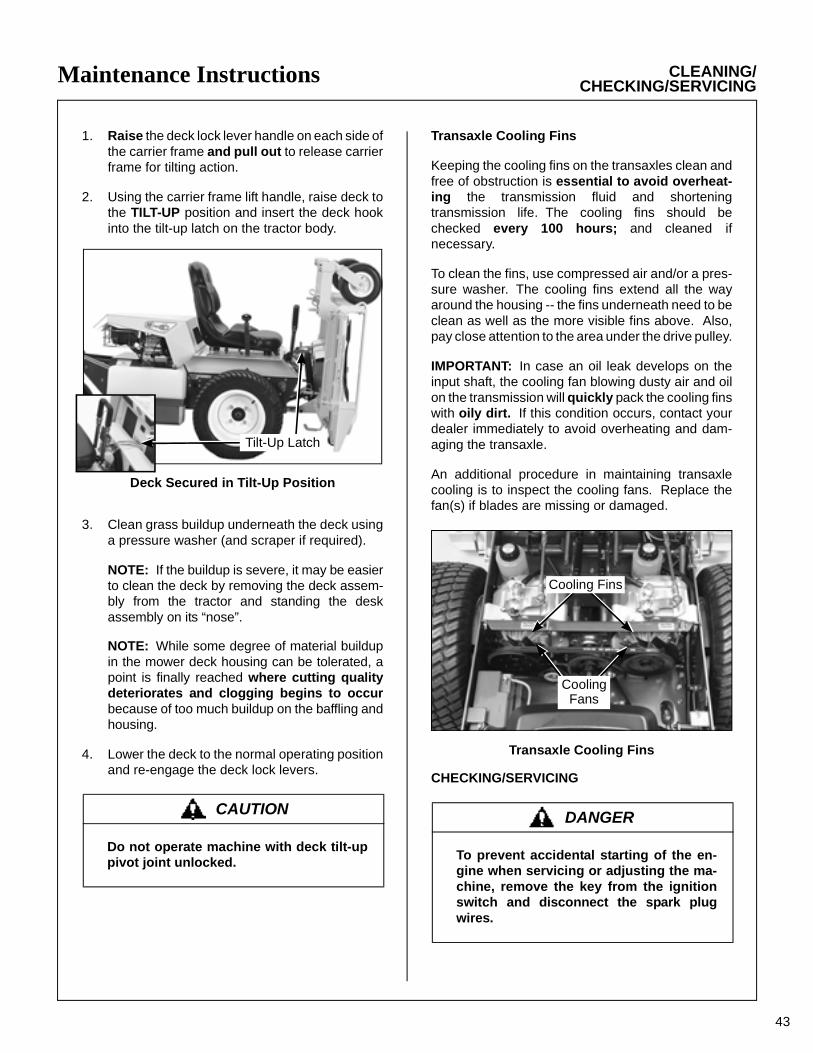
Maintenance Instructions CLEANING/CHECKING/SERVICING
1. Raise the deck lock lever handle on each side ofthe carrier frame and pull out to release carrierframe for tilting action.
2. Using the carrier frame lift handle, raise deck tothe TILT-UP position and insert the deck hookinto the tilt-up latch on the tractor body.
Deck Secured in Tilt-Up Position
3. Clean grass buildup underneath the deck usinga pressure washer (and scraper if required).
NOTE: If the buildup is severe, it may be easierto clean the deck by removing the deck assem-bly from the tractor and standing the deskassembly on its “nose”.
NOTE: While some degree of material buildupin the mower deck housing can be tolerated, apoint is finally reached where cutting qualitydeteriorates and clogging begins to occurbecause of too much buildup on the baffling andhousing.
4. Lower the deck to the normal operating positionand re-engage the deck lock levers.
Transaxle Cooling Fins
Keeping the cooling fins on the transaxles clean andfree of obstruction is essential to avoid overheat-ing the transmission fluid and shorteningtransmission life. The cooling fins should bechecked every 100 hours; and cleaned ifnecessary.
To clean the fins, use compressed air and/or a pres-sure washer. The cooling fins extend all the wayaround the housing -- the fins underneath need to beclean as well as the more visible fins above. Also,pay close attention to the area under the drive pulley.
IMPORTANT: In case an oil leak develops on theinput shaft, the cooling fan blowing dusty air and oilon the transmission will quickly pack the cooling finswith oily dirt. If this condition occurs, contact yourdealer immediately to avoid overheating and dam-aging the transaxle.
An additional procedure in maintaining transaxlecooling is to inspect the cooling fans. Replace thefan(s) if blades are missing or damaged.
Transaxle Cooling Fins
CHECKING/SERVICING
CAUTION
Do not operate machine with deck tilt-uppivot joint unlocked.
DANGER
To prevent accidental starting of the en-gine when servicing or adjusting the ma-chine, remove the key from the ignitionswitch and disconnect the spark plugwires.
Cooling Fins
CoolingFans
Tilt-Up Latch
43

44
Maintenance Instructions CHECKING/SERVICING
Security of Air Cleaner System
NOTE: The following inspection is only an externalinspection and should be done without “disturb-ing” the filtration components.
On a daily basis, visually inspect the external condi-tion of the air cleaner cover.
Check for damage. Make sure the cover is in placeand the cover latches are secure - do not run theengine without the air cleaner cover in place andsecure.
Battery
NOTE: For initial battery service during setup, referto Battery Service in Assembly Instructions.
IMPORTANT: Make sure battery is securelymounted in the frame. A loose battery may causedamage to the case resulting in acid leakage andsevere damage to the machine. A hazard may becreated by damage to critical working parts andsafety systems.
Cleaning the Terminals
If battery terminals are corroded, remove batteryfrom the mower. Using a wire brush, remove corro-sion with a solution of one part baking soda andfour parts water. Rinse with clean water. Coat theterminals with petroleum jelly or terminal protectorspray to retard further corrosion.
Charging the Battery
Check the battery charge by measuring the specificgravity of electrolyte; if specific gravity is less than1.225, the battery will need to be charged as follows:
• Charge the battery at 15 amps for 10 minutes.DO NOT exceed 20 amps maximum recommendedcharging rate. Charge until specific gravity is atleast 1.250. Total charging time should not exceedone (1) hour.
Tire Pressure
Inflate tires to pressures shown below:
Deck Caster Wheel = 20 PSI (137 kPa)Drive = 15 PSI (103 kPa)Rear = 20 PSI (137 kPa)
Sharpen Mower Blades
Check mower blade(s) for straightness, sharp-ness, condition of the cutting edge, and balanceevery 10 hours of operation (or more often whenmowing abrasive type grass or operating on sandysoils). Replace blades if worn, bent, cracked, orotherwise damaged (refer to REPLACING/REPAIRING the Mower Blades in this section).Use the following procedure to check and sharpenblades:
NOTE: Keep blades sharp - cutting with dullblades not only yields a poor mowing job but slowsthe cutting speed of the mower and causes extrawear on the engine and blade drive by pulling hard.
1. Stop the engine, remove ignition key, and dis-connect the spark plug wires before raising themower deck to service blades.
2. Raise the deck and secure it in the tilt-up posi-tion (refer to Deck Secured in Tilt-Up Positionphoto in CLEANING of Grass Buildup inMower Housing in this section).
3. Check the blades for straightness by markingthe blade tip position inside the deck housing,and then rotating the opposite end of the bladeto the same position and comparing. If the dif-ference in blade tip track is more than 1/8 in.(3 mm), the blade is bent and should be re-placed.
DANGER
BATTERIES PRODUCE EXPLOSIVE GASES
• Charge the battery in a well-ventilatedarea, so that gases produced while charg-ing can dissipate.
• Keep sparks, flames, and smoking ma-terials away from the battery at all times.
• Make sure the battery cap vents are open(check manifold vent on each cap).
• Make sure the battery charger is un-plugged before connecting or discon-necting cables to the battery.
DANGER
NEVER operate cutter blades with thedeck in the raised position.

Maintenance Instructions CHECKING/SERVICING
4. If the blade cutting edge is dull or nicked, itshould be sharpened. Remove blades forsharpening by grasping the end of the bladeusing a rag or a thick, padded glove, while loos-ening and removing the nut, lock washer, andflat washer that mounts the blade.
5. Grind cutting edge at the same bevel as theoriginal. Sharpen only the top of the cuttingedge to maintain sharpness.
NOTE: Blades can be sharpened with an elec-tric blade sharpener, conventional electricgrinder, or a hand file.
6. Check blade balance by positioning the bladehorizontally on a blade balancer or use a nail orshaft through the center hole. If either end of theblade rotates downward, grind (remove) metalon that end until the blade will balance. Theblade is properly balanced when neither enddrops. Balance of a blade is generally main-tained by removing an equal amount of materialfrom each end of the blade when sharpening.
Mower Blade Profile For Sharpening
Blade Balanced on MagneticWall-Mounted Balancer
7. Mount the blade with wing tips pointing up intothe housing. Reinstall the blade, washer, lockwasher, and nut. Tighten the nut to 60 ft-lb(81.3 N·m).
Drive Belts
Raise the body and inspect the condition of the two(2) drive belts after every 25 hours of operation --engine/PTO drive and ground drive. If the belts showsigns of cracking or deteriorating, the beltsshould be replaced. Refer to REPLACING/REPAIR-ING the Drive Belts in this section.
Mower Deck Gearbox Oil Seals
The mower deck gearbox seals should be inspectedevery 25 hours for evidence of oil leaking; particu-larly the lower oil seal on the blade drive gear-box. This seal is protected by the trash guard on theblade hub and seal protector plate on the housing,but is still vulnerable to seal damage due to operatingin an adverse environment. The mower blade mustbe removed for inspection of the seal, so it is recom-mended to inspect the gearbox seals whenblades are removed for sharpening. If an oil leakis noted, the seal should be replaced and the gear-box assembly relubricated. Refer to Mower DeckGearbox Lubrication in this section.
WARNING
DO NOT try to straighten a blade that isbent. NEVER weld a broken or crackedblade. ALWAYS replace with a new bladeto assure safety.
CAUTION
ALWAYS wear eye protection and gloveswhen sharpening a blade.
Wing Tip
Do Not Grind orSharpen on Underside
30°
Sharpen at Original30° Angle
IntersectionWear Area
Blade Balancer
45

46
Maintenance Instructions CHECKING/SERVICING/REPLACING/REPAIRING
Spark Plugs
Every 100 hours, remove the spark plugs, inspect,clean, and reset the gap (or replace with a newplug). Clean spark plug with a wire brush. If theelectrodes are burned short or pitted, replace theplug (refer to Specifications for the proper type ofreplacement plug). Check the spark plug gap with awire-type feeler gauge and set the gap between0.028 and 0.032 in. (0.7 and 0.8 mm). Reinstall andtighten to 17 ft-lb (23 N·m). Both spark plugs should bereplaced yearly.
Breaker Points
The Briggs & Stratton engine is equipped with elec-tronic ignition. No breaker points, maintenance, oradjustments are necessary with this system. Con-tact an authorized Briggs & Stratton engine dealer incase of ignition failure.
Fuel Lines and Clamps
Every year, inspect the fuel line from the tank toengine for deterioration or damage. Also, inspect thefuel line clamps for tightness. Good preventivemaintenance calls for complete replacement of fuellines and clamps every two (2) years.
Blade Brake Action
Check the function of the cutter blade brake byengaging the blade clutch (PTO), operating theengine at full throttle, then disengaging the clutchand measuring how quickly the blades stop. Watchthe rotation of the blade drive shaft as a visual indi-cation that movement has stopped. If the brake isworking properly, all rotation will stop five (5)seconds after disengagement of the clutch. If thebrake system malfunctions -- blades do not stop infive (5) seconds -- repair the brake before operatingthe mower.
REPLACING/REPAIRING
IMPORTANT: ALWAYS use genuine factory re-placement parts. Substitute parts CAN result inproduct malfunction and possible injury to the oper-ator and/or others.
Drive Belts
There are two (2) individual belts on the machine:
• Engine/PTO Belt
• Ground Drive Belt
The belts may be removed and replaced using theprocedures described on the following pages.
WARNING
It is important to check and maintain bladebrake action for safe operation of the ma-chine.
DANGER
To prevent accidental starting of theengine when replacing parts or repairingthe machine, remove the key from theignition switch and disconnect the sparkplug wires.
Belt Locations
Engine/PTOBelt
Ground Drive Belt

Maintenance Instructions REPLACING/REPAIRING
47
Engine/PTO Belt
1. To remove the engine/PTO belt:
a. Remove belt guard from underneath muf-fler. Refer to Remove Belt Guard photo.
b. Relax the belt by depressing the spring-loaded idler arm.
c. Roll the belt off the pulley and remove thebelt.
Remove Belt Guard
Remove Bolts to Access Engine/PTO Belt
Push Idler Pulleyto Relax Belt
Idler Pulley
Idler Arm
ElectricClutch Idler
Pulley
Engine/PTOBelt
TensionSpring
PTO DrivePulley
TensionSpringIdler Pulley
Idler Arm
ElectricClutch Idler
Pulley
PTO DrivePulley
Engine/PTOBelt
Engine/PTO Belt (Disengaged)
Engine/PTO Belt (Engaged)
2. Reverse the removal procedure to replace theengine belt.

Maintenance Instructions REPLACING/REPAIRING
48
Ground Drive Belt
1. To remove the ground drive belt:
a. Raise the spring-loaded idler to relax belt.
b. Slide belt off pulleys, then release theidler.
Raise Idler Pulley toRelax Belt
LH Transaxle Ground DriveBelt
TensionSpring
RH Transaxle
Drive Pulley
Idler Pulley
Hydro IdlerArm
Ground Drive Belt Assembly (Disengaged)
2. Reverse the procedure to install the grounddrive belt.
LH Transaxle Ground DriveBelt
RH Transaxle
Drive Pulley
Idler Pulley
Hydro Idler Arm
Ground Drive Belt Assembly (Engaged)
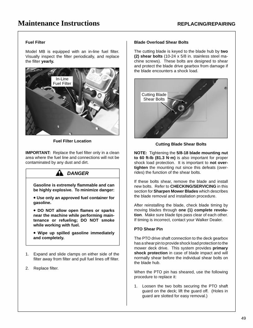
Maintenance Instructions REPLACING/REPAIRING
Fuel Filter
Model MB is equipped with an in-line fuel filter.Visually inspect the filter periodically, and replacethe filter yearly.
Fuel Filter Location
IMPORTANT: Replace the fuel filter only in a cleanarea where the fuel line and connections will not becontaminated by any dust and dirt.
1. Expand and slide clamps on either side of thefilter away from filter and pull fuel lines off filter.
2. Replace filter.
Blade Overload Shear Bolts
The cutting blade is keyed to the blade hub by two(2) shear bolts (10-24 x 5/8 in. stainless steel ma-chine screws). These bolts are designed to shearand protect the blade drive gearbox from damage ifthe blade encounters a shock load.
Cutting Blade Shear Bolts
NOTE: Tightening the 5/8-18 blade mounting nutto 60 ft-lb (81.3 N·m) is also important for propershock load protection. It is important to not over-tighten the mounting nut since this defeats (over-rides) the function of the shear bolts.
If these bolts shear, remove the blade and installnew bolts. Refer to CHECKING/SERVICING in thissection for Sharpen Mower Blades which describesthe blade removal and installation procedure.
After reinstalling the blade, check blade timing bymoving blades through one (1) complete revolu-tion. Make sure blade tips pass clear of each other.If timing is incorrect, contact your Walker Dealer.
PTO Shear Pin
The PTO drive shaft connection to the deck gearboxhas a shear pin to provide shock load protection to themower deck drive. This system provides primaryshock protection in case of blade impact and willnormally shear before the individual shear bolts onthe blade hub.
When the PTO pin has sheared, use the followingprocedure to replace it:
1. Loosen the two bolts securing the PTO shaftguard on the deck; lift the guard off. (Holes inguard are slotted for easy removal.)
DANGER
Gasoline is extremely flammable and canbe highly explosive. To minimize danger:
• Use only an approved fuel container forgasoline.
• DO NOT allow open flames or sparksnear the machine while performing main-tenance or refueling; DO NOT smokewhile working with fuel.
• Wipe up spilled gasoline immediatelyand completely.
In-LineFuel Filter
Cutting Blade Shear Bolts
49

50
Maintenance Instructions REPLACING/REPAIRING
2. Rotate U-joint on shaft to align the shear pin holewith the hole (and shear pin fragment) in theshaft. Use a punch to drive the remaining portionof the old shear pin out.
3. Install new shear pin and secure with cotter pin.
PTO Shear Pin
IMPORTANT: Use only Walker P/N 8067-13shear pins for replacement to provide propershock protection -- these pins are hardened toshear under a specific amount of load.
4. Reinstall the PTO shaft guard.
Before operating the deck, inspect the blade over-load shear bolts and also check blade timing (on geardriven decks) by moving blades through one (1)complete revolution. Make sure blade tips passclear of each other. If timing is incorrect, contact yourWalker Dealer.
Mower Blades
Mower blades are removed and remounted as de-scribed in the Sharpen Mower Blades instructions.During the course of sharpening and inspectingmower blades, if there are any of the following con-ditions of wear or damage, blades should be re-placed for reasons of safety and performance of themachine:
• An excessive amount of the flat section of theblade has been ground away (removed) when theblade is sharpened. Replace the blade when lessthan a 3/4 in. (19 mm) flat section remains at theblade tip.
• Examine ends of the blade carefully, especially theintersection where the flat section of the blade turnsup to form the “wing tip” (refer to Mower Blade Pro-file For Sharpening illustration in Sharpen MowerBlades instructions). Since sand and abrasive ma-terial can wear metal away in this area, the bladeshould be replaced when metal thickness hasworn to 1/16 in. (1.6 mm) or less.
• Check the blades for straightness by markingblade tip position inside the deck housing and then ro-tating the opposite end of the blade to the same po-sition and comparing. If the difference in blade tiptrack is more than 1/8 in. (3 mm), the blade is bentand should be replaced.
• Inspect the blade surface, especially in formedareas, for cracks. Replace the blade if any cracksare found.
Reinstall the blades following procedure from Sharp-en Mower Blades instructions. If blades are re-placed, always use Walker original equipmentblades to ensure safety and optimum performance.The quality and performance of replacement bladesoffered by other manufacturers cannot be guar-anteed, they could be dangerous.
Cotter Pin
U-JointTube Assembly
Shear Pin
Split Spring Pin
U-JointShaft Assembly
Set Screw
DANGER
When blades are operated over sandy soil,and if blades are allowed to wear, a “slot”may be worn into the wing tip of blade.Eventually a piece of the blade may breakoff creating a serious potential for injury ordamage.
WARNING
DO NOT try to straighten a blade that isbent. NEVER weld a broken or crackedblade. ALWAYS replace with a new bladeto assure safety.
CAUTION
ALWAYS use genuine factory replacementparts. Substitute parts CAN result in prod-uct malfunction and possible injury to theoperator.

Maintenance Instructions ADJUSTMENTS
ADJUSTMENTS
Transmission Control
IMPORTANT: The proper adjustment of the transax-le control stops is essential for efficient operationand life of the transaxle. These stops are properlyadjusted at the factory and should only require read-justment if the transaxle or related control linkage isremoved or changed.
NOTE: It would not be unusual for a new machine,after initial 5 or 10 hours of operation, to begin to nottravel straight (this is due to the break-in of the tran-saxles).
Steering Lever Position Adjustment - Step 1
NOTE: For proper operation, the steering leversshould be adjusted to sit evenly using the followingprocedure.
1. Examine the steering levers to make sure theyare parallel front to back in relation to one an-other. If they are not equal, adjust accordingly.(The handles may or may not be even at thispoint.)
NOTE: The LH steering lever is non-adjust-able. This procedure will require adjustment ofthe RH lever to make it even with the LH lever.
Lever Alignment
2. Adjust the position of the RH lever by turning thestop bolt in the Speed Control Actuator in or out.Turning the stop bolt in will make the RH levermove back, and turning it out will make it moveforward. Tighten the lock nut.
Stop Bolt Location
Stop Bolt Adjustment
Steering Handles Adjustment - Step 2
1. An adjustment range of approximately 3 inchesis available on the steering handles - the han-dles can be adjusted forward or aft dependingon the arm length of the operator. The handlescan be adjusted by loosening the lock nut at thepivot point and the lock nut holding the handle inposition in the adjustment slide. Adjust the han-dles into the most comfortable position andtighten both lock nuts.
Levers should sit parallel to each other
StopBolt
51
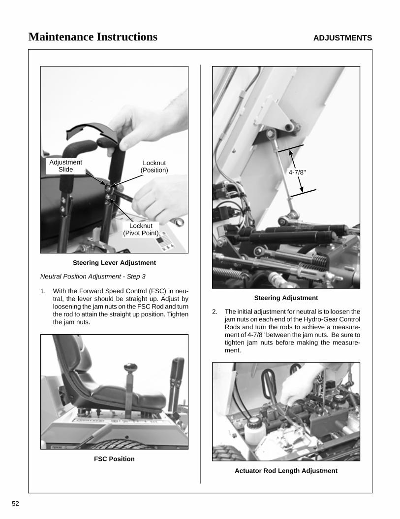
52
Maintenance Instructions ADJUSTMENTS
Steering Lever Adjustment
Neutral Position Adjustment - Step 3
1. With the Forward Speed Control (FSC) in neu-tral, the lever should be straight up. Adjust byloosening the jam nuts on the FSC Rod and turnthe rod to attain the straight up position. Tightenthe jam nuts.
FSC Position
Steering Adjustment
2. The initial adjustment for neutral is to loosen thejam nuts on each end of the Hydro-Gear ControlRods and turn the rods to achieve a measure-ment of 4-7/8" between the jam nuts. Be sure totighten jam nuts before making the measure-ment.
Actuator Rod Length Adjustment
Locknut(Position)
AdjustmentSlide
Locknut(Pivot Point)
4-7/8"
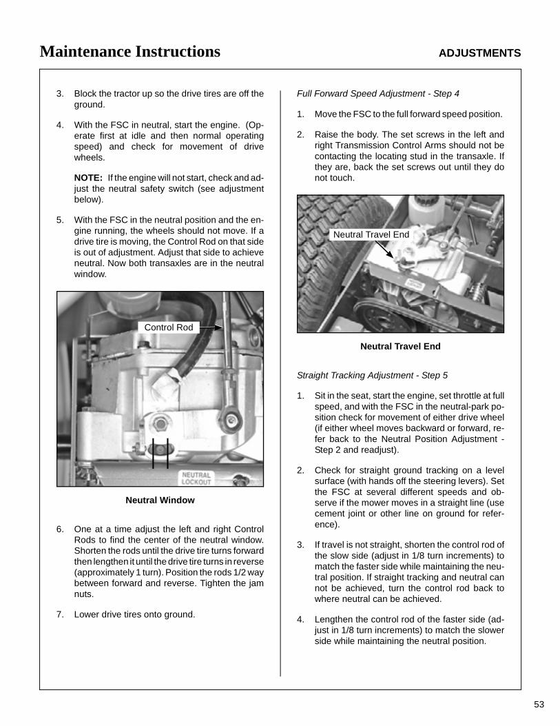
Maintenance Instructions ADJUSTMENTS
3. Block the tractor up so the drive tires are off theground.
4. With the FSC in neutral, start the engine. (Op-erate first at idle and then normal operatingspeed) and check for movement of drivewheels.
NOTE: If the engine will not start, check and ad-just the neutral safety switch (see adjustmentbelow).
5. With the FSC in the neutral position and the en-gine running, the wheels should not move. If adrive tire is moving, the Control Rod on that sideis out of adjustment. Adjust that side to achieveneutral. Now both transaxles are in the neutralwindow.
Neutral Window
6. One at a time adjust the left and right ControlRods to find the center of the neutral window.Shorten the rods until the drive tire turns forwardthen lengthen it until the drive tire turns in reverse(approximately 1 turn). Position the rods 1/2 waybetween forward and reverse. Tighten the jamnuts.
7. Lower drive tires onto ground.
Full Forward Speed Adjustment - Step 4
1. Move the FSC to the full forward speed position.
2. Raise the body. The set screws in the left andright Transmission Control Arms should not becontacting the locating stud in the transaxle. Ifthey are, back the set screws out until they donot touch.
Neutral Travel End
Straight Tracking Adjustment - Step 5
1. Sit in the seat, start the engine, set throttle at fullspeed, and with the FSC in the neutral-park po-sition check for movement of either drive wheel(if either wheel moves backward or forward, re-fer back to the Neutral Position Adjustment -Step 2 and readjust).
2. Check for straight ground tracking on a levelsurface (with hands off the steering levers). Setthe FSC at several different speeds and ob-serve if the mower moves in a straight line (usecement joint or other line on ground for refer-ence).
3. If travel is not straight, shorten the control rod ofthe slow side (adjust in 1/8 turn increments) tomatch the faster side while maintaining the neu-tral position. If straight tracking and neutral cannot be achieved, turn the control rod back towhere neutral can be achieved.
4. Lengthen the control rod of the faster side (ad-just in 1/8 turn increments) to match the slowerside while maintaining the neutral position.
Control Rod
Neutral Travel End
53

54
Maintenance Instructions ADJUSTMENTS
5. If the forward travel is straight throughout thespeed range, except at maximum speed - placethe FSC in full forward, turn the set screw in theTransmission Control Arm, of the faster side, inuntil it contacts the hydro stud. (Turning the setscrew in slows the wheel.) Turn the set screw inan additional 1/8 turn. Recheck for equal full for-ward speed. Adjust this set screw until equal fullforward speed is achieved. Tighten the jam nut.
Neutral Travel End Adjust
Neutral Switch Adjustment - Step 6
1. Place the FSC in neutral position. Loosen thebottom lock nut and adjust switch body up withtop nut until the switch contacts open. Turn thenut an additional 1 turn. Tighten lower nut.
FSC Switch Location
Forward Speed Control Friction Adjustment - Step 7
FSC Position With Levers
1. Place the FSC in the full forward position andpull both steering levers back; the FSC levershould not move. If the FSC lever moves backthe friction needs to be increased.
2. With the steering levers held back, move theFSC lever back from the forward position. Witha proper amount of friction adjusted, the FSC le-ver should move back with a slight amount of re-sistance (friction). If the FSC lever movement is"stiff", the friction needs to be decreased.
3. The FSC friction is increased or decreased bytightening or loosening the friction adjustmentnut. Loosen or tighten the nut and check thecontrol function until the conditions of bothsteps 1 and 2 are met.
FSC Switch

55
Maintenance Instructions ADJUSTMENTS/ELECTRICAL SYSTEM
Tilt-Up Deck Adjustable Stop
When the carrier frame hinge joint is properly ad-justed, the deck lock levers should move in and outof the engaged and disengaged positions freely. Allfour hitch pins used for height adjustment should sitflush on the washers above the deck pin bushing.On a level surface, if any pin is sticking up (likely thefront pins), tighten the opposite side or loosen thesame side to lower the pin. Adjustments are madeby loosening the jam nut and tightening or loosen-ing the set screws on the Deck Mount Pivot Brack-ets. Retighten the jam nut when the adjustment iscomplete.
Tilt-Up Deck Adjustable Stop
ELECTRICAL SYSTEM
For troubleshooting, refer to the Wiring Schematic.
IMPORTANT: Disconnect both battery cables be-fore unplugging any wiring connectors or making re-pairs on the electrical system.
Set Screw
Jam Nut

ITEM PART DESCRIPTION LOCATION NO. NO. NO. REQ’D SD
#�����)����+���� ��������,���(����,��< 8&&�������������.�".3"
56
�!"��!����"#$
����������� �����%��� ���������
� "/3� �����=�+&��+�����0��� ��!) �� "/"* =!��7��#%' ��!) �� "/3�.� 06����!�� ��!)��06�%�!��>���%�� � /3* ��!����+��� ��!) �" "/3�.� 26����!�� ��!)��26�%�!��>���%�� �* 1/3 '����0����+� ��� �- 3� .� ����2������� ��� �
��������������� ������������������ ���������
/ "/3" �+������8������8��+� 2�����!) �1 -/�/ �������2�!�=�+� ��!) ��3 �3-.� ����������� ����+�! ��� �3-. �����������2�+���� ����+�! �
���� ������������
�� -/31 ����������������� ��!)��26�%�!������9�%�� ��� */-" ����'����(����'���9 #�������$������+���'�(��) �� �3"./ ����:26���/6�� ��!) ��" �3".1 ����:06���/6�� ��!) �
���� '���,�����;+������!���������,,�!�9����!����,,���!<

8&&�������������.�".3" #�����)����+���� ��������,���(����,��<
57
�!"��!����"#$
Refer to DecksParts Manualfor Deck Decals
8
10
5
2
4 7
12
9
13
7
10
11
6
63
1
15
14

ITEM PART DESCRIPTION NO. NO. NO. REQ’D
ITEM PART DESCRIPTION NO. NO. NO. REQ’D
������������������������ ������������� ��� �����������������������
58
��� ����������������
�������������
� ���� ���� �� ���� ������� ��� ���� �� ���� !��� ��������� ���"�#��$��% �& �'&� (�))� �*���� �"������$��+�% �� �'&� (������ �,��-� �"�#'�$����#&% ++ �'&+ ,��-� �"�#'�$����#&�$��#'% &� ���& �-���.� �*���/������0����� �' �&&��� �-��1�0�����"���#&�$��#&% �
������������
2 &��� (�� �*�.�"3����.���3����4���% ��� &��� 5 ����*�. ��� &�2� 3����������5���� �. ��� &����� !����-�6�� . ��� &����� ���� �6�� . ��& �'&� (�))� �*���� �"�����$�����% ��� ��'� �.��0��.��#7��� �8����� ��+ &��&�� 9����"�2:% �
����������������
�� &2���� *���� �9��.���;�� ���� ��' ��&���� (�))� �0��/�<��9����"��$�+% ��2 &+&��� =����,��-�/�79 ��� &+&��� =����,��-�/�(9 ��� &����' !-������6�� ./�7�;� �5 ��� ��� &��� !-������5 ���� ��� &��� *�.�6��.� ��& ���� �$���������� ���"�#&�$��% ��� �'�& �������=��/�(�. ��+ ��'��� *�.�7���-�9��1 ��� 2�&+ 6���=��1�0���� ��' &�&� *�.������ ��(�. ��2 &�&��� �� ���!���� ��� ���� �$���������� ���"�#&�$����#�% �
�������������������
�� ��+��� (������ �!���� �"�:% �"3����.���3����4�5&��%
�� ������ �����*�� ��� ��� �&���� =����,-����5� 1� ��& ������ *�� ��/�=����,-��� ��� ���� =����,-����>�=� ��?����)��"���$�+����+% �
������ =����,-����=� ��"���$�+����+% ���+ =����,-����>�9�)�"+�$�&��%
�+ ���'�� ?$�������� �=�)��"+��#'% �
��!���"##��������$����!������������
�� �'�� 6 �����5����� ��' &����2 ���1������ ��? ��0���� �
"3����.���3����4���%
�2 &&�� ���1������ ��? �#79 �&� ������ 9���-� ���"4+% �&� &&�� ���1������ ��? �#(9 �
����%&#����!����������
&� �'&� �������=�� �&� ��&&��� �� ���? �/�=�������7���- �&& ��&&��� �� ��� �����*��-�� �&� ��&&��� !��� ��������� ���"�#'�$��#'% �&+ ��&&��� 0�����?���/�79 �&� ��&&��� 9��1/�=�������7���- �&' ��&&��& 0�����?���/�(9 �
'����(���
5��� ����&�@����<�� '5��& �#&����@����<�� �'5��� �#&������<?�<�� �5��2 �#�+��'�,-�A�7��1��� ��5��� �#'��+�,-�A�7��1��� &5��+ �#����������7��1���<�� �5��� �#�+��'���<?�<�� �5��� ����&���<?�<�� �5��� ����&�$��#'� 90� 25��' ����&�$��#&� 90� �5��2 �#&����B��#��9�$�*��� &5��& �#�+��'�$��#&�9�$�*��� +5��� ����&�$��#'� =9��� �; �5�&' �#���?��,��-� �5�2� �#�+��'�$���9�$�*��� �5��+ �#&����$����#&�9�$�*��� �5��� ?<2+�&�+�,��-� �5��� �#�+�$��#��!���� � �� �5��� �#&����$��#&�!� ����*��� �5�'� �#&�$��#'�$��#'�,��-� �5��� �#'�$����#&�$��#'�,��-� �" ������% �5�&+ �#&����$��#�� =90� ��5�2� �#�����$�'��#��9�$�*���/�6(�� �5�2� �#�+�$����#���������� ��� �� �5�&� !����(���� ���"�#+&�$�2#�+% �5�&� �#�+�!�������,��-� �5�2� �#'��+�$����#&�9�$�*���� &5&�� �#�+��&�$��#�+������� �;� �
�� ����� � ��8��
!�������� =������� 7���-� ?����)�� @��� ������)��� )� � .� ��1�� 4 ��&��

8&&�������������.�".3" #�����)����+���� ���������,���(����,��<
59
&�'�(��)"$$�$�"$$��&#'
46
47
48
F029F020
4544
F341
F342F342
F004
F0294342
F093
F004
F002
F002
F028
1
4140
4039
F295
F295
27
2
9
11
10
13 1232
17
18
19
36
35
34
8
F009
F246F004
F023
F034
14
F009
F004
F002
F025
F029
F120
F127
30
29
8
3
45
16
21
38
37
22
23
15
F009
F227
F009
F009
F005
F034
F002
F116
F172
F029
F009
F009
F004
28
26
25
24
F037
F034
6
7F025
F182
F004
F034F004
F029
F009
F013 5 F393
F048
F292
F016
F413
F048
34
F025
33
32
31
20

ITEM PART DESCRIPTION NO. NO. NO. REQ’D
ITEM PART DESCRIPTION NO. NO. NO. REQ’D
#�����)����+���� ���������,���(����,��< 8&&�������������.�".3"
60
�"������������ �!��!"�$��$$��
���������"����*+
� -3*.� 8��������%,�����4�: ��� 5 �� -�3�.� �#�������� �� "/�3 ������������� � ��" ������������������� �
47���+!��7��(�?��5" -�3�. 7�����2���4�.�:�5 �* "/ � 2������� ����4�:/����.�: 5 �- � ".� %������)�7!����'�(� �/ � ".� 7!�����+���)�4 :���5 �1 ��3 8�����:��������:=����!�%�� ��3 �3.� ��+����%,���� ��� �3 8����������+���� ��� *��".� %,�����+�����4":�*5 ��� ��* �����������+���)�4":''5� �
47���+!��7��(�?���"��A���-�5� "�*� �����9������������� ��" �- ����������%�&� ��* "�-".�" #.$������+��:1<"@��'0�%,���� �
47���+!��7��(�?��3-*5�- �33.- ������+�! �
��� �����
�331 ":�*.�/� ��C�0����+� �3�� �:/.�*�B�,�>+� ��3�� �:/.�*� ��C�0����+� "�3� ":�*.�/����: �6������� �3�/ �:/.�*�����6������� �3 � �:/.�*����.�: �6������� ��3 � �:/.�*����.�: �6������� ��3"� �:/�%'8� ��� ��3*� �:/�7�������%���0���� ��� ��3-* �:/.�*���":/�%E6�%���%���9 ���"� �:/.�*���-:/�6������� ���"� �:�*����:�*����.�: �B�) ���-� ":�*.�/����:/�%���%���9 ���-/ �:/�%,����0���� ��� ���/- �:/.� ��.�:��6�������� �
� %��������������)

8&&�������������.�".3" #�����)����+���� ���������,���(����,��<
61
�"������������ �!��!"�$��$$��
F012
F013
F042
F063
F063
F171F012
F151
7
32
8
85 6
1
4Refer toEngine Group
Refer toBody / Chassis Assembly
10
11
13
12
9 F051
F051
F051
F153
F042
F041F278 F387
F013
14
F038
14
15
16
3
F038
F076
F038
F013
17
F034
F009
F038
F153

ITEM PART DESCRIPTION NO. NO. NO. REQ’D
ITEM PART DESCRIPTION NO. NO. NO. REQ’D
#�����)����+���� ���������,���(����,��< 8&&�������������.�".3"
62
��0����0!/�
�������"����*+
� / " 2+������+(,���4�<3���<*�"5 �� �3 .� ��!)�%+,,���� �� 3��.� =+&&�����+�! � �3 .1 6���%����!:'�+(��+( �" >% �/�6��8������4������A�%��������"3 -5 �
���������"����*+
* 3�3." �:/�>���%������0 �- "3�3 �+���������� �/ "/-1.� 6�����(,�4�:�5� �1 "3/*." 6���4�: �����5� ��3 "3/* �+���0����47�������:#5 ��� "3/�.� �+������2+�����4����"3/�5 ��� "3/�.� �����+���8���9� ��� "3/�.� �+����,�%��� �� "3/� �+��������,� �
47���+!��7��(�?���5�" 3 * �+���������<3���<�� �
4�+����,��������!547���+!��7��(�?����A�� 5
�* "3�3.� �+�����������7������ �
�,���������,�� ��"����*���
�- "1-".� ���������4"3?���-@5 ��/ �3/.� ��������:�����������4"*.�:�5 ��1 "�-� ��������>)����4<�""�7����<�-1������<�"35 ��3 "�3/.- ��������0������ ��� "�3/.�3 ��������� ����4<��"5 ��� "�3/./ ��������������� ��� "�3/.� ��������0��������������:������ �� "�3/." �����������������B���:2�! ��" "�3/.* ��������������B���:���� ��* -�3/ ��������'�(��) �
�3/ ������������������!����� �'�(��)�47���+!��7��(�?�� 5
�31 ���������������!����� �'�(��)�47���+!��7��(�?��"5
��� �����
�33� �3.� �B�,�>+� "�33 �: .�3�B�,�>+� *�33" �: .�3�8%>'�>+� ��331 ":�*.�/� ��C�0����+� *�3�" �3.� ����:/���6=% �3�� �: .�3����: �6������� ��3"3 �: �%'8� ��� /��* �3.� ����: ����:/�%60����� ���-1 �: .�3���7�6������� ���/ �: .�3����:��6���������%% ���/" �: �7�������%���0���� ��� ���3� �: ������������%,����� ��� ���"" ":�*.�/����.�:��6������� ����* ":�*.�/����.�: �6������� ���1� �: .�3�����%���%���9��%%��+,������ �
� %��������������)

8&&�������������.�".3" #�����)����+���� ���������,���(����,��<
63
��0����0!/�
F164
F050
F201
F002
F002 F025
F005
5
10
16
18
1
1
F004
F004 F050
F392
F004
F050
F032
F050
F009F009
F179
2
F255
F185
F316
128
14
20 21
19
24
25
26
13
15
78
9
F185F184
F184
F009F009
22
Refer toBody / ChassisAssembly
Refer toHydrostatic GroundDrive Assemblies
11
17
23
3
4
6
F004
F050

ITEM PART DESCRIPTION NO. NO. NO. REQ’D
ITEM PART DESCRIPTION NO. NO. NO. REQ’D
������������������������ ������������� ��� �����������������������
64
�� ��������� ��������������������
���������� ���!!�"#���!
� ������ ���� ��� � ��� $� ���� !����"������������ ��� �
#$����%���$�����&�'�(��)' *+ *�� �� ������ !������� ��� �,����-�. �� *+ /��0� �1 ������ !����"������������ ��� ���2�3 �4 �54��' .���� �����#�-�) �5 ��51�� .����#�-��"�����-�) �� *+ ��6���2�3 ��� ���5�' .% ��7��8������% ��� �����' !������� ��� �,����-7. ��� �'���� +� ���,�����9���� ��' �'���� :����%�;�� ��� ��� ���� � ����9�����#���-�<) �
#$����%���$�����&�:�14�(�:�4�)�� �'���' .% ��� ����+0��� ��1 �'���� :��"� �������.����#'-��;� �) ��4 �'�� +��%� =�:��"�2��� ������� ��5 �'���� :��"� �������.����#�>�;� �) ��� �5�� ������� �/��0� �#'-5�"����-�) ��� ���� $%�� �9�����#'-<) ��� 4����� $��� ������#���-�) ��� 4����' ���;�� ��� ��' �'���� .% ��$%�� �< �� ��� �5'� ? �����:������ ��� ���� �"��������+� ���#'-��"��) ��1 ���5 ? ���%�� ����;���� ��4 ��44 ? ������#�-��"��'-�1�"�'-�1) ��5 ���� .% ��?�� �/- 0� ��9���-7. �
�� ������ 9� 8���; �8��< ��@��� $'� ���1 .% ��?�� �/- 0� ��9���-�. �
'� ������ .% ��!���:���� � $
%�����&��������!!�"#�'
'� 4��1�� .��%���? ��-��% �'' ���1�� 9� 8���; �8��< ��<����2� �'� ���1�� ; �8��<������ �9��� �'� �11� ��� �������+� ���#�-��"��) �'1 ���1�� ������.���� �'4 ���1�' ������.���=�+� ���+�%� �'5 4��'�� ������9���#�-��"��-5) �'� �����' ���� ��+� ���#�-��"���1') ��� ���1�4 9� 8���; �8����%�,���� ��� ���1�' 9� 8���; �8��,�����<����2� ��� ���4�� 9� 8�; �8��<������ �7��8 �
�(�����!!�"#�'
�' ��4� 79�/0����(�A� ��<����2��#�5�"�5������) ���4��� 79�A� ��#�5�"�5������) $��4��� 79�/0����#���"�4) $��''�� /0����(�A� ��<����2��#�5�"�1����5) $$��'��� +���%� %�A� ��#�5�"�1����5) $��'��� +���%� %�/0����#5�"����) $��'��� A� ��A�2��#�5�"�5����5) $
)�!*����!
:��� �-�����@����*�� 5:��� �-������+*<�*�� ':��� �-�1��5�/0�B�7��8��� �:��� '-5��1�@����*�� ':��' '-5��1�/0�B�7��8��� �:��� �-�����/0����7��*�� 5:��� �-�����"��-��.�"�;��� 1:�'� �-�����"��-5�.�"�;��� �:��� '-5��1�"����-��.�"�;��� �:��' '-5��1�"�'�.�"�;��� �:��� '-5�+<��/��0� �:��� <*�1�1�1�/��0� � �:�11 �-��"��-��"�'-��@� �:�14 '-�1�"�'-�1�"���@� �:�1� '-'��"��-�� ���� �9�� ':��� �-5�"�'-�� ���� �9�� �:�1� �-�1��5�"��� � ����;���� �:�4� �-�1��5�"�'-5�+���+� �3 �:'�1 '-5��1�"�'-��.�"�;���� �:��1 1���"��������3���9��� �
$ +� �����9� ��!��
$$ ,�� 2�� � %� �%� ��� �� ����� ���������%� ������� � � �� � %���� ��������������*� �3�� ����A� ���� �����%�30���������������'1>���8�� ��������� �/��8� ������ �

������������� ������ ����������������������������������������
65
�� ��������� ��������������������
4
F004
F029
11
F004F029
F005
F013
F00922
21
24
F043
53
67
8
Refer toEngine Group
30
28
31
29
8 7
7
97
9
25
2
1910
F005F040 F051
10
3
53
F406
F406
32
33
34
43
43
42
4041
42
6
2 1
1
F066
37 36
35
38
39
F069
F012
F067
F015
F306
20
23
1213
14
15
27
18
F067
F171F171
F029
F111
F069
F012
F111
F069
F031
F069
F004
F004
F005
Refer toBody / ChassisAssembly
3
26
F169
F169
1617
F054

ITEM PART DESCRIPTION NO. NO. NO. REQ’D
ITEM PART DESCRIPTION NO. NO. NO. REQ’D
������������������������ ������������� ��� �����������������������
66
��� ��������������� �
�����������������������������
� ���� � !�"��# �� $�%� � !�&��� �'����#�
()����*���)����+�,-, ��,� . ����������� �$ ���$�� /����0�����(�1����$1&2-�314� ��* �� $�%, � !�5�* �� ���$�$ /����0�����(�1����$-�314� ��* �% $��6 �7�������� � ���(,1$�7����1�- �� $$���$ � !�� �������'������ �6 ���$�� /����0�����(�1����$-�(8����&���*- ��� $��, 2* ��.�� �!��� ���5�* ��� 6��$ 3��9� �(�1��7�%1�- ��� $��� : �����������!��� ���' � ��, $����� ��� ���&��� �������� ��$ ��$� �����/���� ��* $�� $��� ��� ���������� �;���� ��� ���$�, /����0�����(�1����$�&2-�(8����&���*- ��% ��,��, . ������������($�����- ��� $$���� ��� ���<����� 9����31 ��� ��6 6%�$�, <�����5�*�/��9��1<������ ��� $�$��� � !�� �������3��9� �
(���1��7����1,��7��1��-�� ��$� � !�� �������3��9� �
(���1��7�,1��7��1��-�� $�$��� � !�!��� ��, $$���� ��� ���<�����(�1$����7����1�- ��$ $$���, ���*�!��� ���'������ 1&2 �
()����*���)����+��%-�� ���� �7�������� � ���(�1��7�,��1$- ��� �$�� ��!��� ��% $$���$ ��� ���&��� �:�#��31:�# ��� �$�,��� ��� ���&��� �2��*��1'*=� �
()����*���)�����+��6�>��,$�-�6 ������ 2��*���. ��?������(���1�- �,� $$���� ���*�!��� ���'������ 152� �
()����*���)����+�,-
���������!��"���������������
,� $�66 : ����������� � ���'����#� ()����*���)�����+�,��,�?����$?���,�?�,���>��,��-
,� $��� /����0�����(�1$���- �,, ��6��� � ���<���� �(������- �,$ ��6$ <���� � ����� �,� ��6, 3��9� �(,1$�7���7�����- �,� ��6� � ��� ��*��($�,1$- �,% ��6� !��� ���� � ���(��7����1�- �,� ��6� � ��� ��*��!�� �
���������
���, �1$����2�7�8�� ����$ �1$����"����8�� $���� �1$����� 8'�8�� ����� �1����$�"����8�� ����6 �1������39�@�&��A��� �6���� �1����$�� 8'�8�� ����$ �1����$�0���8�� ,��,� �1$����7��1��2�7�/���� ���,� �1������7����1$�2�7�/��� ���6, �1������7���2�7�/��� ���$� �1$����0���8�� ����% �1������2�7�8�� ����, �,���7��%���7���%$�3��9� $���� �1$���� ����&��A���8�� $��6� ,1���$� ����&��A���8�� ���6� �����7������7���$��3��9� ?� ����� �1$����7�%1��2�7�/��� ���,� �1������7����1��2�7�/��� ���,�� ,1��7�,1�� 9���*� �/���� ��,�� �1��7�,1$� ����� � ���<�� ��,$� �1$����7��%%��"�� ��*�/��� $�,�� �1,��7���2��������5����<�� ��,%, �1����$&2�2�7�8��� ,�,�� �1$�7����1$�5����<��� ��,�� �1������7����1��7�,1�� 9���*� �/��� ��,6� �1$����7��1�� ��� � �B?� � ��$�% /����������3��9� �,1��7�����%� �
� �����<� ��4��

8&&�������������.�".3" #�����)����+���� ���������,���(����,��<
67
$���!��0����!#�"$$��&#��$
F391F146
Refer toBody / ChassisAssembly
F010
F008
119
F009F183
F1833
6
30
22 21
20 19
19
F312
24
23
23
F005
F009F009
F005
F192
F407
F004
F004
F211
3
5
F386
F183
F024F093
1
2
4
7
F385
8
12
Refer toBody / ChassisAssembly
F010
F008 F391F146
119
12
F093
F183
2625
2625
1431
10
1614
17
18
31
F024
F235F373F009 F004
10
16
29
2928
27
27
28
13
14
F345
F188
F167F035
F198
F373
F024
F373
F008
F003F352
F320
F00433
32
3435
3637
38F004
F009
F009F008
F009
F188
F345F198
F009
15 Refer toHydrostatic GroundDrive Assemblies
Refer toHydrostatic GroundDrive Assemblies
F031
F031
F031

ITEM PART DESCRIPTION NO. NO. NO. REQ’D
ITEM PART DESCRIPTION NO. NO. NO. REQ’D
#�����)����+���� ���������,���(����,��< 8&&�������������.�".3"
68
�#���!��"#�"$$��&#'
��� �����"����*+
� /1*3.�" 7��������%9����� :B�)� �47���+!��7��(�?��-���/�A��� 15
� 1"3 ����%9����� �� *1 � 2��)�%9������3: 3'=��4>�5 � -1 �.� ����������+���������� �" -1 �.* ����+����������4�"'=�5 �* "1 �.� %9����������4�����:>�"1 �5 �- "1 � %&��)�%9�����4>�5� �/ "1-"." �������,��%��&.=�+��� �1 /113.� 6�+�(�����4%��!��5 ��3 "/�" �������(,�4�: 5� ��� *1�� �����)������4.5 ��� 1 3. �����)��������@�4H5 ��� -/�� ������(,�4��:�*���?�35 �� 1 3.� %������%������!������4 .�:�@5 ��" 1�1 %������%������!� ��* 1�3 �����)�4��':��35 ��- -/" ��������,��2�!� ��/ /1*3.� B�)�%��� :#(����� ��1 1 3 ����6��� �
��� �����
�33� �3.� �B�,�>+� �33 �: .�3�B�,�>+� ��331 ":�*.�/� ��C�0����+� ��3�" �3.� ����:/���6=% ��3�* �3.� ����:����6=% ��3�/ �3.� ����: ���6=% ��3�1 �: .�3����:��6������� ��3�� �: .�3���":/�6������� ��3� ":�*.�/����: �6������� ��3*� �: �%���0���� ��� ��3/* ?�3�%'8� ��� �� 1 ����</�"�7���<��������%% ���- �3.� �6���>+�� �

������������� ������ ����������������������������������������
69
�� ����������
B
D
FE
AG
H
I
YEL
PURBLK
RED BLKRED
RED
END VIEWS ARE SHOWN FROM BACK OF PLUG
DETAIL IDETAIL CDETAIL A DETAIL D
PURPUR\WHT BRN
BRN\WHT
GRA
YEL YELRED/YEL PUR/WHT
DETAIL H
GRA RED/WHT
DETAIL B
PURPUR
YEL WHT
BLKRED
PURPUR
RED
RED
DETAIL G
BRN/WHTBLK
DETAIL E
REDBLU
WHTWHT
BLK
BLKBLK
DETAIL F
RED/WHTBLU
BLKBLK
YEL
YEL
BLK BRN
C
Refer toHydrostatic GroundDrive Assemblies
Refer toMain ComponentPower Transmission
Refer toBody/ChassisAssembly
Refer toBody/ChassisAssembly
F002F025
9
8
F025
3
11
17
18
6
7
1
4
2
5
F349
F002
F034
F009
F004 F061
F004
F002F028
F374F086
F026
F374
10 1113
16
6
7
F029F031
15
19 12
14

ITEM PART DESCRIPTION NO. NO. NO. REQ’D
ITEM PART DESCRIPTION NO. NO. NO. REQ’D
������������������������ ������������� ��� �����������������������
70
�� ��� ��������� �������
��� �������� ������ ���������������������������� !�������� ���������"����� ���������#��$��� �� ������������ �������������������%��������� �&��'� ������ �
� ()���* &��+� �,���-�. �� �/)� 0������ �&��+� �,1-/�2����-). �1 ))���� #����!�3� ����42�� �) /(* �/ �����%��!����'�%���� �� /(* �* 5�� ���%����,�6���. )* /(* �� 5�� ���%�� )( ()���) 7� '�#�����8�$��,����������������*. �/ /(* �( 3��� � ()���� 8����7� '!�3� ����42�� ��� /�1 9��!�8����&+����42�� ��� /�1/�� 3���� !�8����&+����42�� ��� /(*/�� 3���!�0��� ���:�� ��1 /�1( 5�� ���%����,1-)���. )�) /�1� 8����&+����"�8� ��4����$��,�1�2������*. �
,&��+�5�� ���0���.(�1��� 8����&+����8� ��,�1�2������*. �/�1* &+����"�;�$�,*�2�1���. �/�1(�� 5�� ���0��� �
�� /�1(�� 3���!�<��� �,��1-)�2����-/. ��* (�1/ 8����&+����42���,1-)�2��� -�*. ��( ()���( =�����3+����,��2����-). ��/ �*/1 =�����5�� �� �� �/1� > �����7����� 1
�!��"��!
7��1 1-/��*�&+�?�:��'���� �7��* �-���1�3����:��'���9�� �7�1/ 1-/��*�2���;�2�5��� �7�)* 1-/��*�2�1��-��;�2�5���� �7�)� (-�*��)�2���;�2�5��� )7��� �-�*��/�2��-)�3���3� �@ �7��/ (-�*�3�����:��'�&��+� )7�(/ 1-/�3�����:��'�&��+� �71)) 1-)��*�3�������;�2�9�� �71)( 1-)�34��&��+� �71)/ �-/�2����-��%���� �=�� �71(( �-���1�2���;�2�5��� �
� 3� �����=� ��<��

8&&�������������.�".3" #�����)����+���� ���������,���(����,��<
71
�$�!�"���"�#� )��#�"2#��3��
Refer toBody / Chassis Assembly
F0161
F140
F205
F218
F278 F038
4
F046
2F013
3F278F038
F377
56
7
658
9
F140
F218
1315
16
1718
1819
1919
F344F347
F348
1213
101114
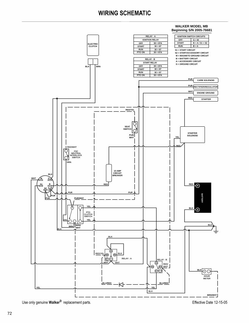
���� ���� ������� � ��� ��������
�� � ��� � ���
���� ��� ������� � ��� ��������
�� � ��� � ���
#�����)����+���� ���������,���(����,��< 8&&�������������.�".3"
72
�!��0�$�)��"���
HOUR
METER
B
A
M
S1
S2
G
15 AMPCIRCUIT
BREAKER
BA
TT
ER
Y
WALKER MODEL MB
Beginning S/N 2005-76681
S1 = START CIRCUIT
S2 = START/ACCESSORY CIRCUIT
M = MAGNETO GROUND CIRCUIT
B = BATTERY CIRCUIT
A = ACCESSORY CIRCUIT
G = GROUND CIRCUIT
ENGINE GROUND
RECTIFIER/REGULATOR
CARB SOLENOID
ELECTRICCLUTCH
STARTER
STARTER
SOLENOID
PTOCLUTCHSWITCH
RUN
RELAY - A
IGNITION RELAY
OFF
START
PTO ON
30 + 87
30 + 87
30 + 87A
30 + 87A
IGNITION SWITCH CIRCUITS
OFF
START
RUN
G + M
B + A / S1 + S2
B + A
RUN
RELAY - B
START RELAY
OFF
START
PTO ON
30 + 87
30 + 87
30 + 87A
30 + 87A
PUR
BRNBLK
BLK
WHT
PUR
RED
RED
RED
PUR/WHT
PUR/
WHT
PURPUR
GRA
BRN
PUR
PUR
RED
BLK
BLK
BLU/RED BLU/RED
YELYEL
WHT
WHT
BRN/WHT
BRN/
WHT
YEL
YEL
YEL
GRA
RED/YEL
SEAT
SWITCH
FSCNEUTRAL
INTERLOCKSWITCH
87
30
8586
RELAY - B
RED/WHT
RED/
WHT
BLK
BLK
87 87A
30
8586
RELAY - A
WHT
BLK
BLK
BLK
RED/YEL
87A

73
LIMITED WARRANTYFOR
WALKER MODEL MBRIDER MOWER
1. WHAT THIS WARRANTY COVERS, AND FOR HOW LONG:
Walker Manufacturing company will, at its option, repair or replace, without charge, any part covered by this warranty whichis found to be defective in material and/or workmanship within one (1) year after date of sale to the original retail purchaserunless the product is used for commercial or rental purposes, in which case this warranty is limited to ninety (90) days. AtWalker’s request, customer will make the defective part available for inspection by Walker and/or return the defective partto Walker, transportation charges prepaid. All parts and components of the Walker Mower are covered by this warrantyexcept the following components which are warranted separately by their respective manufacturers:
Briggs & Stratton EngineHydro-Gear TransaxlesBatteryTires
The available warranties covering these items are furnished with each mower. Walker does not assume any warranty obli-gation, liability or modification for these items, which are covered exclusively by the stated warranty of the respective man-ufacturers noted above.
2. WHAT THIS WARRANTY DOES NOT COVER:
A. This warranty does not cover defects caused by depreciation or damage caused by normal wear, accidents, impropermaintenance, improper use or abuse of the product, alterations, or failure to follow the instructions contained in theOwner’s Manual for operation and maintenance.
B. The customer shall pay any charges for making service calls and/or for transporting the mower to and from the placewhere the inspection and/or warranty work is performed.
3. HOW TO OBTAIN SERVICE UNDER THIS WARRANTY:
Warranty service can be arranged by contacting the dealer where you purchased the mower or by contacting Walker Man-ufacturing Company, 5925 East Harmony Road, Ft. Collins, CO 80528. Proof of the date of purchase may be required toverify warranty coverage.
4. WARRANTY LIMITATION:
A. THERE IS NO OTHER EXPRESS WARRANTY. ANY WARRANTY THAT MAY BE IMPLIED FROM THISPURCHASE INCLUDING MERCHANTABILITY AND FITNESS FOR A PARTICULAR PURPOSE IS HEREBYLIMITED TO THE DURATION OF THIS WARRANTY AND TO THE EXTENT PERMITTED BY LAW ANY AND ALLIMPLIED WARRANTIES ARE EXCLUDED. Some states do not allow limitations on how long an implied warrantylasts, so the above limitations may not apply to you.
B. WALKER WILL NOT BE LIABLE FOR ANY INCIDENTAL, CONSEQUENTIAL, OR SPECIAL DAMAGES AND/OREXPENSES IN CONNECTION WITH THE PURCHASE OR USE OF THE MOWER. Some states do not allow theexclusion or limitation of incidental or consequential damages, so the above limitation(s) or exclusion(s) may notapply to you.
C. Only the warranty expressed in this limited warranty shall apply and no dealer, distributor, or individual is authorizedto amend, modify, or extend this warranty in any way. Accordingly, additional statements such as dealer advertisingor presentations, whether oral or written, do not constitute warranties by Walker, and should not be relied upon.
D. This warranty gives you specific legal rights, and you may also have other rights which vary from state to state.

WFO
Sound - Model MB Vibration - Model MB
Sound Test
ALKER MRM NO. 12
Lwa97
OPERATOR
LpA83
0.6g
Sound test conducted was in accordance with 2000/14/EC and was performed on 31 May 05 under the conditions listed:FG. CO. • 5925 E. HARMONY ROAD,1505 PRINTED IN USA www.
General Condition: Clear
Temperature: 65 (F)o18 (C)o
Wind Speed: < 5 mph (< 8 kmh)
Humidity: 25%
Barometric Pressure: 83.8 kPA
Vibration Level
FORT COwalkermowe
Genera
Tempe
Wind S
Humid
Barom
Vibration levels at the operators handles were measured in the vertical, lateral, and longitudinal directions using calibrated vibration test equipment.
Tests were performed on 14 July 04 under the conditions listed:
LLINS, CO 80528 • (970) 221-5614rs.com ©2006 WALKER MFG. CO
l Condition: Clear
rature: 50 (F)o10 (C)o
peed: < 5 mph (< 8 kmh)
ity: 52%
etric Pressure: 24.9" HG (759 mm Hg)
TM