owner’s manual & installation instructionsledguy.net/pdf/backup/etl5000_ownman.pdfetl 5000...
TRANSCRIPT
OWNER’S MANUAL & INSTALLATION INSTRUCTIONS
002IS007 Rev. 04/07

ETL 5000 BASICSThis is a basic configuration showing many of the features offered. Your ETL 5000 may have a different
configuration. This diagram should only be used as a reference.
4 TOP COVER SCREWS
INBOARD LED MODULES
TAKE DOWN MODULES
CORNER LED MODULES
ELECTRICAL ENCLOSURE
TOP VIEW WITH COVER ON
TOP VIEW WITH COVER OFF
WIRE EXIT
BOTTOM VIEW CARRIAGE BOLTSFOR MOUNTINGBRACKETS
Back
Front
MODEL NUMBERSERIAL NUMBER
Page 1

ETL 5000 BASICS
ADJUSTABLE HEIGHT BRACKET(SOME ASSEMBLY REQUIRED)
HEIGHT & ROOF ANGLE ADJUSTMENT SCREWS
VEHICLE SPECIFIC BRACKETADJUSTMENT SCREW
VEHICLESPECIFICBRACKET
PIVOTARM
FRONT TO BACK TILT ADJUSTMENT SCREWS
ADJUSTABLE RUBBER FEET
HEIGHT ADJUSTMENT SCREWS
BREAKOUT BOX
Page 2

PRE-INSTALLATION
Unpack box - 1. Remove the light bar and packaging.2. Save packaging for later shipping.3. Check components/contents.4. Please reference this instruction manual for proper wiring and installation.
Components/Contents1 - ETL 5000 LED Lightbar1 - Mounting Kit 2 - Adjustable Height Mounting Brackets 2 - Mounting Bracket Gaskets 2 - 1/4”-20 x 1.5“ Screw 2 - 1/4”-20 Square Nuts 2 - Vehicle Specific Brackets 8 - #8 x 1/2“ Phillips Drive Sheet Metal Screws 2h - 39” x 1” x 1/2” Foam Strips 1 - Roofside Cable Grommet 4 - 1/4”-20 Acorn Nuts 12 - 1/4” Split Lockwashers 4 - 1/4” Flat Washers1 - Breakout Box (optional)
Tools Required for Installation:5/32” Allen Driver7/16” Socket with ratchetPhillips Head Screwdriver Electric Drill with #30 (.128 dia.) drill bit1 1/4” Hole Saw
At anytime during your installation process, feel free to call our technical support line
at 1-800-338-7337. You can also visit our website at www.soundoffsignal.com or email
technical assistance at [email protected].
DRILLING ANY HOLES INTO THE LIGHTBAR IS NOT RECOMMENDED! THE RISK OF DAMAGING INTERNAL COMPONENTS AND THE RESULTING FAILURE OF THE LIGHTBAR WILL VOID ANY WARRANTY OF THIS PRODUCT.
IMPORTANT NOTICE TO INSTALLER: Make sure to read and understand all instruction and warnings before proceeding with the installation of this product. Ensure that the manual and any warning cards are delivered to the end user of this equipment. Proper installation of the lightbar requires the installer to have a thorough knowledge of automotive electronics, systems, and procedures. Lightbars provide an essential function of an effective visual warning system. The use of the lightbar does not insure that all drivers can or will abide by or react to an emergency warning signal, especially at high rates of speeds or long distances. The operator of the vehicle must never take the right of way for granted and it is the operator’s responsibility to proceed safely. The effectiveness of the this lightbar is highly dependant on the correct mounting and wiring. The installer must read and follow the manufacturer’s installation instructions and warnings in the manual. The vehicle operator should verify daily that the lightbar is securely fastened to the vehicle and properly functioning before operating vehicle. The lightbar is intended for use by authorized personnel only. It is the user’s respon-sibility to ensure they understand and operate the emergency warning devices in compliance with the appli-cable city, state and federal laws and regulations. (SoundOff signal assumes no liability for any loss result-ing from the use of this warning device.)
Page 3
ETL 5000 INSTALLATION1. Test your lightbar: Using a high current power supply or +12-volt automotive battery only, test your new ETL 5000 prior to installation onto the vehicle to verify your bar is properly configured and functioning properly. This test can be done using the included wiring schematic and electrical installation power up test steps 2-4 and lightbar configuration and pattern setup steps 1-2.
2. Review ETL 5000 basics and understand descriptions.
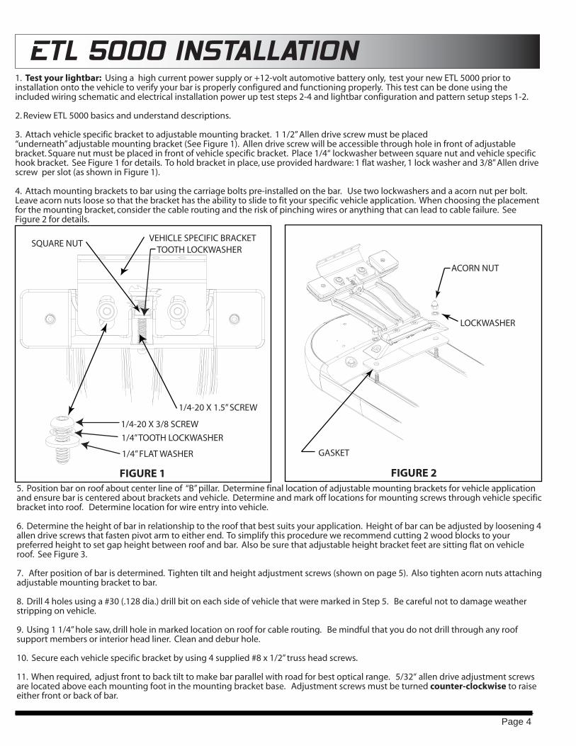
3. Attach vehicle specific bracket to adjustable mounting bracket. 1 1/2” Allen drive screw must be placed “underneath” adjustable mounting bracket (See Figure 1). Allen drive screw will be accessible through hole in front of adjustable bracket. Square nut must be placed in front of vehicle specific bracket. Place 1/4“ lockwasher between square nut and vehicle specific hook bracket. See Figure 1 for details. To hold bracket in place, use provided hardware: 1 flat washer, 1 lock washer and 3/8” Allen drive screw per slot (as shown in Figure 1).
4. Attach mounting brackets to bar using the carriage bolts pre-installed on the bar. Use two lockwashers and a acorn nut per bolt. Leave acorn nuts loose so that the bracket has the ability to slide to fit your specific vehicle application. When choosing the placement for the mounting bracket, consider the cable routing and the risk of pinching wires or anything that can lead to cable failure. See Figure 2 for details.
5. Position bar on roof about center line of “B” pillar. Determine final location of adjustable mounting brackets for vehicle application and ensure bar is centered about brackets and vehicle. Determine and mark off locations for mounting screws through vehicle specific bracket into roof. Determine location for wire entry into vehicle.
6. Determine the height of bar in relationship to the roof that best suits your application. Height of bar can be adjusted by loosening 4 allen drive screws that fasten pivot arm to either end. To simplify this procedure we recommend cutting 2 wood blocks to your preferred height to set gap height between roof and bar. Also be sure that adjustable height bracket feet are sitting flat on vehicle roof. See Figure 3.
7. After position of bar is determined. Tighten tilt and height adjustment screws (shown on page 5). Also tighten acorn nuts attaching adjustable mounting bracket to bar.
8. Drill 4 holes using a #30 (.128 dia.) drill bit on each side of vehicle that were marked in Step 5. Be careful not to damage weather stripping on vehicle.
9. Using 1 1/4” hole saw, drill hole in marked location on roof for cable routing. Be mindful that you do not drill through any roof support members or interior head liner. Clean and debur hole.
10. Secure each vehicle specific bracket by using 4 supplied #8 x 1/2” truss head screws.
11. When required, adjust front to back tilt to make bar parallel with road for best optical range. 5/32“ allen drive adjustment screws are located above each mounting foot in the mounting bracket base. Adjustment screws must be turned counter-clockwise to raise either front or back of bar.
Page 4
SQUARE NUT
1/4-20 X 1.5” SCREW
FIGURE 1
VEHICLE SPECIFIC BRACKET
1/4-20 X 3/8 SCREW
1/4” TOOTH LOCKWASHER
1/4” FLAT WASHER
TOOTH LOCKWASHER
FIGURE 2
LOCKWASHER
ACORN NUT
GASKET
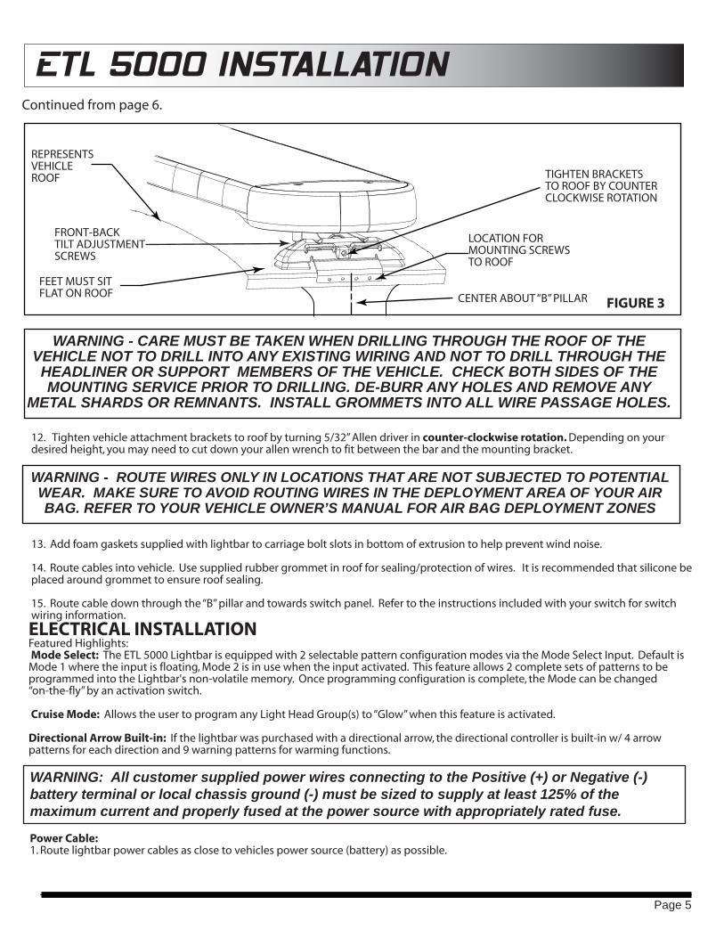
ETL 5000 INSTALLATION
LOCATION FOR MOUNTING SCREWS TO ROOF
FEET MUST SIT FLAT ON ROOF
TIGHTEN BRACKETSTO ROOF BY COUNTER CLOCKWISE ROTATION
FIGURE 3
REPRESENTSVEHICLEROOF
CENTER ABOUT “B” PILLAR
FRONT-BACKTILT ADJUSTMENTSCREWS
Continued from page 6.
12. Tighten vehicle attachment brackets to roof by turning 5/32” Allen driver in counter-clockwise rotation. Depending on your desired height, you may need to cut down your allen wrench to fit between the bar and the mounting bracket.
13. Add foam gaskets supplied with lightbar to carriage bolt slots in bottom of extrusion to help prevent wind noise.
14. Route cables into vehicle. Use supplied rubber grommet in roof for sealing/protection of wires. It is recommended that silicone be placed around grommet to ensure roof sealing.
15. Route cable down through the “B” pillar and towards switch panel. Refer to the instructions included with your switch for switch wiring information.
WARNING - CARE MUST BE TAKEN WHEN DRILLING THROUGH THE ROOF OF THE VEHICLE NOT TO DRILL INTO ANY EXISTING WIRING AND NOT TO DRILL THROUGH THE HEADLINER OR SUPPORT MEMBERS OF THE VEHICLE. CHECK BOTH SIDES OF THE MOUNTING SERVICE PRIOR TO DRILLING. DE-BURR ANY HOLES AND REMOVE ANY
METAL SHARDS OR REMNANTS. INSTALL GROMMETS INTO ALL WIRE PASSAGE HOLES.
WARNING - ROUTE WIRES ONLY IN LOCATIONS THAT ARE NOT SUBJECTED TO POTENTIAL WEAR. MAKE SURE TO AVOID ROUTING WIRES IN THE DEPLOYMENT AREA OF YOUR AIR BAG. REFER TO YOUR VEHICLE OWNER’S MANUAL FOR AIR BAG DEPLOYMENT ZONES
WARNING: All customer supplied power wires connecting to the Positive (+) or Negative (-) battery terminal or local chassis ground (-) must be sized to supply at least 125% of the maximum current and properly fused at the power source with appropriately rated fuse.
Power Cable:1. Route lightbar power cables as close to vehicles power source (battery) as possible.
ELECTRICAL INSTALLATIONFeatured Highlights: Mode Select: The ETL 5000 Lightbar is equipped with 2 selectable pattern configuration modes via the Mode Select Input. Default is Mode 1 where the input is floating, Mode 2 is in use when the input activated. This feature allows 2 complete sets of patterns to be programmed into the Lightbar's non-volatile memory. Once programming configuration is complete, the Mode can be changed “on-the-fly” by an activation switch.
Cruise Mode: Allows the user to program any Light Head Group(s) to “Glow” when this feature is activated.
Directional Arrow Built-in: If the lightbar was purchased with a directional arrow, the directional controller is built-in w/ 4 arrow patterns for each direction and 9 warning patterns for warming functions.
Page 5

ETL 5000 INSTALLATIONIMPORTANT: When passing cables through firewall or other sheet metal, insert grommet to protect the cable!
2. Install a 40AMP Fuse (customer supplied) to the end of the RED wire of the Lightbar Power Cable. a. Remove the fuse before connecting any wires to the battery. b. DO NOT USE CIRCUIT BREAKER OR FUSIBLE LINK.
3. Connect the other end of the Fuse to the POSITIVE (+) terminal of the battery. a. Do NOT use any more than 2ft of wire between the battery terminal and the fuse and ensure the wire is protected and secured from being cut into; this is non-fused wire.
4. Connect the BLACK wire to the factory chassis ground right next to the battery.
Control (Data) Cable:1. Route Lightbar Control Cable to the location where all controlling equipment will be, i.e. switch box, center console area.
2. Locate the Breakout Box in the same area to connect jumpers from the switching equipment to the breakout box.
NOTE: Power is supplied to Breakout Box through data cable, no additional power connections necessary.
Initial Power up Test:1. Insert 40AMP Fuse into Fuse Holder.
2. Plug data jack into Data 1 connector of the breakout box (Data 2 may also be used, but is for future use.)
3. Observe the GREEN Data Link indicator LED on the Breakout Box; the LED will turn steady ON about 3 seconds after main power is connected
4. When GREEN LED is steady ON, the lightbar is ready to be configured.
Pattern Selection: a. First review the Pattern Table (included on pg. 7) before attempting pattern selection to familiarize yourself with patterns available for the different Functions i. Depending on the Lightbar configuration purchased, the Arrow Pattern Table may or may not be applicable. b. Select the Input Function(s) and apply +12V to activate. i. To change patterns on more than one input function, simply connect desired input functions together. Before doing this, make sure all the inputs are using the same pattern table and are on the same pattern to make pattern identification easier. c. Momentarily apply +12V to advance to the next pattern. See Flash Pattern Table below. i. Once the last pattern is reached, the next pattern advance will cycle back to Pattern #1. d. Once the desired pattern is reached, simply disconnect the Input Function(s) and proceed to the next Input Function(s) to be configured. i. The pattern is saved in non-volatile memory every time it is advanced.
Mode Configuration: See Mode Input on Function Description Table (attached sheet) for more details about this feature. a. Mode 1 (Default): the Mode Select Input will be floating (no-connection) i. Continue on to Pattern Selection instructions below to set the patterns for this Mode b. Mode 2: apply +12V to activate Mode 2. This will need to be activated to configure the Lightbar in Mode 2 i. Continue on to Pattern Selection instructions below to set the patterns for this Mode ii. Once patterns have been setup, connect Mode Select Input to switching system. iii. When the Mode Select Input is activated, the Mode 2 Patterns will flash.
Cruise Mode Configuration: See Cruise Mode Input on Function Description Table (attached sheet) for more details about this Feature. a. Apply +12V to activate Cruise Mode for configuration setup. b. Determine what Input Function(s) are desired to use Cruise Mode. c. Apply +12V to the Input Function(s) desired. i. NOTE: Lights will flash preset flash pattern d. With both the Cruise Mode Input and the Input Function(s) activated, momentarily apply +12V to the pattern select wire to toggle the Cruise Mode to ON (default is OFF). e. Observe the OFF sequence of the flash pattern is ON dim. f. Disconnect the Input Function wire(s) (while leaving cruise mode input active) and observe the lightbar is NOT flashing, but the output function(s) recently set are glowing steady.
Page 6

ETL 5000 INSTALLATIONFlash Pattern Table
Page 7
LED Module Flash Patterns
Patte
rn #
Patte
rn
Nam
e
Sequ
ence
Flas
hes
/ M
inut
es
Flas
hes
/ Se
cond
1 Quint Alternating 70 1.182 Warp Alternating 350 5.883 Inter-Cycle Flash Alternating - -4 Quad Flash Alternating 80 1.355 Road Runner Alternating 115 1.926 Road Runner Simultaneous 115 1.927 Slow Runner Alternating 70 1.168 Slow Runner Simultaneous 70 1.169 Q-Switch Variable - -10 Single, Steady Burn Steady Burn 115 1.9211 Quad, Steady Burn Steady Burn 80 1.3512 Warp, Steady Burn Steady Burn 350 5.8813 E-Pattern Single Flash Alternating 230 3.8514 E-Pattern Double Flash Alternating 128 2.1315 E-Pattern Single Flash Simultaneous 230 3.8516 E-Pattern Double Flash Simultaneous 155 2.60
Halogen Take-Down & Alley Flash Patterns1 Road Runner Alternating 115 1.922 Power Pulse Alternating 180 3.003 Q-Switch Variable - -4 ETM Simultaneous 214 3.575 Steady Burn Steady Burn - -
Directional Bar Warning Function Patterns1 Power Pulse Alternating Center Out 180 3.002 Power Pulse Alternating Left/Right 180 3.003 Quad Alternating Center Out 80 1.354 Warp Alternating Adjacent 350 5.885 Cross-Fire 2x Individual Sweep - -6 Hyper Scan Pulsing + Sweep - -7 Super Scan Dual Rate Pulse/Alt - -8 Power Flash Dual Rate Alt/Pulse - -9 Thunder & Lightning Random - -
Directional Bar Directional Function PatternsFor Left, Center Out, & Right Sequences
1 Solid Arrow Plus, Slow Grow / Decay2 Solid Arrow, Slow Solid3 Individual Arrow, Fast Individual4 Chaser Arrow, Fast 2x Individual
Breakout Box Hookup:1. Make appropriate connections between Terminal Blocks on Breakout Box, matching the pin location to the function you desire. See Breakout Box Function Diagram
2. Secure wire from the switch box into terminal block and pull on each wire after you fasten them to ensure you have a secure connection.
3. Once all wires have been secured to the Terminal Block, plug the Terminal Blocks into their respective locations
4. Tighten the Terminal Block security fasteners and pull on the Terminal Block to ensure it does not move or pull back.
Troubleshooting:Your lightbar now should be fully operational. If it is not functioning properly, check your connections for the following: 1. The positive (RED) wire is properly connected to the battery using user supplied fuse block. 2. 20 AMP fuse is installed in fuse block. 3. The ground (BLACK) is properly connected to the factory ground. 4. Check to make sure the GREEN LED on the breakout box is steady ON. 5. Check internal fuses in lightbar. These can be accessed by removing for screws in top cover (see ETL 5000 basics on page 1 & 2) and four screws in top cover of electrical enclosure. Fuses will be located on power input side of electrical enclosure. Replace any blown fuses with correct amperage rating of fuse removed. 6. If the lightbar still does not function properly, please contact our technical support at 1-800-338-7337.

ETL 5000 INSTALLATION
Page 8
Light Bar Controller Connector Instructions
Input Group Control Light Output GroupsFront Corners CNR1 alt. CNR4Rear Corners CNR2 alt. CNR3
Front Inboard 1 FIN1 & 9 alt. FIN4 & 12Front Inboard 2 FIN2 & 8 alt. FIN5 & 11Front Inboard 3 FIN3 & 7 alt. FIN6 & 10Rear Inboard 1 RIN1 & 9 alt. RIN4 & 12Rear Inboard 2 RIN2 & 8 alt. RIN5 & 11Rear Inboard 3 RIN3 & 7 alt. RIN6 & 10
Front Tk-dwn Flash TD1 & TD2 alt. TD3 & TD4*Alley Flash ALDRV alt. ALPAS
Modules Locations5 RIN4 through RIN86 RIN4 through RIN97 RIN3 through RIN98 RIN3 through RIN10
Arrow Module Usage Table**
'* TD2 & TD3 are available only if purchased with 4 Take-down Modules
** If the Lighbar has an Arrow bar, RIN3 through RIN10 are designated for Arrow functions. Rear Input Control Group 3 is completely disabled, and RIN4,5,8,9 of Rear Input Group 1 & 2 are disabled. Rear Input Groups 1 & 2 are active but only with RIN1,2,11,12 outputs.
Inboard example: (With alternating pattern selected) If Front Inboard 1 is activated; FIN1 will Alternate with FIN12. If the lightbar is long enough to require the second pair, FIN9 will Alternate with FIN12 which are placed next to each other on the light bar, and FIN1 will alternate with FIN4 which is placed next to each other on the light bar.
Inboard Module Rules
Location Connector Brake Out BoxOuter Most Module(s): F/RIN1,4,9,12 F/R Input Group 1
Center Module(s): F/RIN2,5,8,11 F/R Input Group 2Inner Most Module(s): F/RIN3,6,7,10 F/R Input Group 3
If length allows and more modules can be placed, start the second output group pair from inner then move to outer.

REPLACEMENT PARTS
Vehicle Attachment Brackets
Take Down Assembly
Alley Light Assembly
Inboard LED Assembly
Corner LED Assembly
Page 9
**See our website at www.soundoffsignal.com for the most recent list of available vehicle attachment brackets.
Part # List Price
PETLCSAAA $173.27PETLCSAAC $173.27PETLCSBBB $252.89PETLCSBBC $252.89PETLCSGGC $261.65PETLCSRRR $173.28PETLCSRRC $173.28PETLCSWWC $261.65
PETLC0000 $44.94Part # List Price
PETLL000 $32.46PETLL00B $32.46PETLL00R $32.46PETLLSAA $100.72PETLLSBB $140.53PETLLSRR $100.73PETLLSAC $100.72PETLLSBC $140.53PETLLSGC $144.91PETLLSRC $100.73PETLLSWC $144.91
Part # List Price
PETLH2C $46.81Part # List Price
PETLM00 $3.18PETLM01 $48.74PETLM02 $104.99PETLM03 $100.55PETLM04 $98.51PETLM05 $111.97PETLM06 $91.15PETLM07 $74.92PETLM08 $101.59
Part # List Price
PETLK00 $160.70PETLJ00 $160.24PETLJ02 $160.24
PETLELENC $475.77PETLLB001 $67.70PETLLB002 $18.45PETLLB003 $35.61PETLLB00T $267.12PETLHDK28 $6.89PETLHDK31 $49.06PETLALEN $12.09PETLAREF $13.33PETLAGAS $5.40PETLFH40 $25.65
PETLGA1016 $2.97PETLGA1015 $2.84PETLWA970 $12.70PETLWA971 $10.03PETLWA972 $95.56PETLWA974 $126.60PETLBU003 $5.21
PETLGA1013 $1.90
Corner Assemblies
Amber-L/Amber-R Amber LensAmber-L/Amber-R Clear Lens
Red-L/Red-R Clear LensWhite-L/White-R Clear LensNo LED's, Gray Lens
Blue-L/Blue-R Blue LensBlue-L/Blue-R Clear LensGreen-L/Green-R Clear LensRed-L/Red-R Red Lens
Inboard Assemblies
Blank Assy Gray LensBlank Assy Blue LensBlank Assy Red LensAmber LED, Amber LensBlue LED, Blue LensRed LED, Red LensAmber LED, Clear LensBlue LED, Clear LensGreen LED, Clear LensRed LED, Clear LensWhite LED, Clear Lens
Takedown Assemblies
2 Lamp Clear Takedown (STD)Mounting Kits
Lightbar Mounting Kit - Perm. Mount KitLightbar Mounting Kit**Lightbar Mounting Kit**Lightbar Mounting Kit**Lightbar Mounting Kit**Lightbar Mounting Kit**Lightbar Mounting Kit**Lightbar Mounting Kit**Lightbar Mounting Kit**
Other Parts
Adjustable LB Mount Kit (Each)Break Out Box Sub Assembly (External)Break Out Box Sub Assembly (Discrete - Ext)Electronics Enclosure & BoardsBreak Out Box Board8X Linear Driver Board16X Linear Driver BoardLightbar MotherboardMounting Screw KitBreakout Box Connector KitAlley Light Lens & ScrewsAlley Light RefractorAlley Light Gasket40 Amp Inline Fuse Holder & FuseRoof Wire Grommet with External BreakoutRoof Wire Grommet with Internal BreakoutTakedown Harness
Neoprene Groove Gasket (19 " Strips)
Alley Light HarnessMain Power CableMain Power Cable for Internal BO BoxAlley/Takedown Halogen Bulb
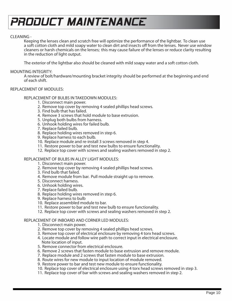
PRODUCT MAINTENANCECLEANING - Keeping the lenses clean and scratch free will optimize the performance of the lightbar. To clean use a soft cotton cloth and mild soapy water to clean dirt and insects off from the lenses. Never use window cleaners or harsh chemicals on the lenses; this may cause failure of the lenses or reduce clarity resulting in the reduction of light output. The exterior of the lightbar also should be cleaned with mild soapy water and a soft cotton cloth.
MOUNTING INTEGRITY: A review of bolt/hardware/mounting bracket integrity should be performed at the beginning and end of each shift.
REPLACEMENT OF MODULES:
REPLACEMENT OF BULBS IN TAKEDOWN MODULES: 1. Disconnect main power. 2. Remove top cover by removing 4 sealed phillips head screws. 3. Find bulb that has failed. 4. Remove 3 screws that hold module to base extrusion. 5. Unplug both bulbs from harness. 6. Unhook holding wires for failed bulb. 7. Replace failed bulb. 8. Replace holding wires removed in step 6. 9. Replace harness to each bulb. 10. Replace module and re-install 3 screws removed in step 4. 11. Restore power to bar and test new bulbs to ensure functionality. 12. Replace top cover with screws and sealing washers removed in step 2.
REPLACEMENT OF BULBS IN ALLEY LIGHT MODULES: 1. Disconnect main power. 2. Remove top cover by removing 4 sealed phillips head screws. 3. Find bulb that failed. 4. Remove module from bar. Pull module straight up to remove. 5. Disconnect harness. 6. Unhook holding wires. 7. Replace failed bulb. 8. Replace holding wires removed in step 6. 9. Replace harness to bulb 10. Replace assembled module to bar. 11. Restore power to bar and test new bulb to ensure functionality. 12. Replace top cover with screws and sealing washers removed in step 2.
REPLACEMENT OF INBOARD AND CORNER LED MODULES: 1. Disconnect main power. 2. Remove top cover by removing 4 sealed phillips head screws. 3. Remove top cover of electrical enclosure by removing 4 torx head screws. 4. Locate module and follow wire path to correct input in electrical enclosure. Note location of input. 5. Remove connector from electrical enclosure. 6. Remove 2 screws that fasten module to base extrusion and remove module. 7. Replace module and 2 screws that fasten module to base extrusion. 8. Route wires for new module to input location of module removed. 9. Restore power to bar and test new module to ensure functionality. 10. Replace top cover of electrical enclosure using 4 torx head screws removed in step 3. 11. Replace top cover of bar with screws and sealing washers removed in step 2.
Page 10
WARRANTY & RETURN GOODS PROCEDURE
Congratulations on the purchase of your new SoundOff Signal product.
This warranty covers failures due to defects in materials or workmanship for a period of up to 5 years from the time of purchase and does not cover normal wear or cosmetic damage. This warranty applies only to units installed according to manufactures installation instructions and operated within the unit specifications. SoundOff Signal retains the right to be the sole mediator of what constitutes defects in performance or manufacturing.
In the event of a failure, and the product falls within its return-or-exchange warranty period, the customer may return it for a replacement or a sales credit to be applied to future product orders. Non-defective returns, if allowed, must be made within the return period. Non-defective returns are subject to restocking fees of 20% - 25%
This warranty is not applicable to any SoundOff Signal product that has failed due to abuse, misuse, improper installation, excessive voltages or alterations to the products that affects, in the manufacturer’s judgment, intended use and service. SoundOff Signal will not be held liable for any incidental or consequential damages and assumes no responsibility of liability for expenses incurred in the use of this product and/or the removal and/or re-installation of products requiring service or repair; nor the packaging, handling, and shipping of the product to SoundOff Signal and/or their authorized distributors.
Warranty Return Process
Please contact your SoundOff Signal Sales Representative, Customer Services staff or our Technical Department (800.338.7337) for a RGA (Return Goods Authorization) number.
The following information is required for issuance of the RGA#:
• Reason for returning the product*• Address where replacement product is to be shipped*• Telephone number where you may be reached*• SoundOff Signal invoice number on which product was purchased**• SoundOff Signal part number and serial number**• E-mail address where RGA# should be emailed**• Fax number where RGA # should be faxed**
SoundOff Signal will NOT accept returns without an RGA number. Each RGA number is good for only one (1) item and will expire (7) days after the date it was issued. Products must be shipped back to SoundOff Signal and the RGA number clearly marked on the outside of the package near the shipping label. Please use the following address on your shipping label:ATTN: RGA#SoundOff Signal3900 Central ParkwayHudsonville, MI 49426
Please see reverse side for manufacturer warranty.
Warranty ExclusionsShipping & Handling, labor and service fees are non-refundable. SoundOff Signal is not liable for any damage due to installation or personal injury as a result of using SoundOff Signal product. Halogen bulbs are also excluded from warranty.
Warranty ForfeitureWarranty will not be granted if the Warranty Return Policy & Procedure rules are not strictly followed. Physical damage resulting from customer abuse will void warranty. Warranty will also be voided if any SoundOff Signal and/or manufacturer serial tags, product stickers, seals, or the like, are removed, altered or tampered with. Returned product that is damaged by shipping via the RGA procedure is not the responsibility of SoundOff Signal.
*RGA will not be given without this information.** If available, please provide this information.
Document effective date January 2006 and supersedes previously dated policies and statements.
There are no other warranties, expressed or implied, including, but not limited to, any implied merchantability or fitness for a particular use. SoundOff Signal reserves the right to modify this warranty statement at any time; or to discontinue, modify, or upgrade any products of its manufacture with design improvement s without prior notice.
ISO-9001 Registered ©2006 SoundOff Signal Emergency Technology Inc. dba SoundOff SignalPrinted in the USA / All Rights Reserved / Specifications subject to change without notice.
PO Box 206 / 3900 Central Parkway / Hudsonville, MI 49426toll free 800.338.7337 / office 616.896.7100 / order fax 616.896.1286 / www.soundoffsignal.com