owners manual hydrus commercial softening … sanitation procedure..... 25 troubleshooting.....26...
TRANSCRIPT

Models:
HS 118s HS 218s OD HS 318s OD HS 418s OD HS 121s HS 221s OD HS 321s OD HS 421s OD HS 124s HS 224s OD HS 324s OD HS 424s OD HS 130s HS 230s OD HS 330s OD HS 430s OD HS 136s HS 236s OD HS 336s OD HS 436s OD HS 142s HS 242s OD HS 342s OD HS 442s OD
Owners Manual Hydrus Commercial Softening Systems

HS Series Owners Manual
Rev. 10/07 Kinetico Incorporated Corporate Headquarters Newbury, Ohio 44065 440-564-9111 Product No. 12223A
Page - 2
Table of Contents The Hydrus Series Commercial Softeners............................................ 3 Operation............................................................................................... 7
Simplex Systems ................................................................................................................... 8 Multiplex Systems’ Regeneration Sequence.......................................................................... 8 Plumbing ................................................................................................................................ 9 Media Tanks .......................................................................................................................... 9 Upper Distributor .................................................................................................................. 10 Media ................................................................................................................................... 10 Underbedding ...................................................................................................................... 10 Lower Distributor .................................................................................................................. 10 Riser Tube ........................................................................................................................... 10 Brining System..................................................................................................................... 10 Central Brining ..................................................................................................................... 11 The Hydrus Valve ................................................................................................................ 11
System Configuration.......................................................................... 12 Sizing ................................................................................................................................... 12 Brining System..................................................................................................................... 13 Remote Meter ...................................................................................................................... 15 Smart Start™ Controller ....................................................................................................... 17
System Maintenance........................................................................... 22 Adding Regenerant .............................................................................................................. 22 Brine Drums ......................................................................................................................... 23 Remote Meter ...................................................................................................................... 24 Battery Replacement............................................................................................................ 24 Softener Sanitation Procedure ............................................................................................. 25
Troubleshooting................................................................................... 26 Frequent Regeneration ........................................................................................................ 27 Hard Water........................................................................................................................... 27 High Salt Consumption ........................................................................................................ 30 Iron Bleed Through .............................................................................................................. 30 Leaks ................................................................................................................................... 31 No Water to Service............................................................................................................. 31 Pressure Loss ...................................................................................................................... 32 Salty Treated Water ............................................................................................................. 32 Taste, Color and/or Odor ..................................................................................................... 33 Unit Sticks in Cycle .............................................................................................................. 34 Water Running to Drain........................................................................................................ 34
Parts .................................................................................................... 36

HS Series Owners Manual
The Hydrus Series Commercial Softeners The benefits of softened water are many:
• Savings in soap products and cleaners • Reduction or elimination of fabric softeners in laundering facilities • Reduction of boiler chemical costs • Reduction in rinse aids that prevent water spotting • Elimination of scale, which inhibits heat transfer
However, the benefits gained by softening in a commercial environment far exceed chemical savings. Commercial facilities invest in high-quality equipment to carry out the daily tasks of operating that business, which is often very expensive. Dishwashers, boilers, laundering equipment and the entire plumbing system is at risk of hardness fouling that can severely limit the equipment’s useful life and can be the cause of costly repairs.
How a Water Softener Works Hard water contains calcium and magnesium ions. Kinetico softeners contain resin beads, which hold sodium ions. When hard water passes through the resin beads, the calcium and magnesium ions are exchanged for the sodium ions held by the resin. Following this ion exchange process, the water leaving is soft. Once the resin bed is loaded with calcium and magnesium ions, it must be cleansed, or regenerated, so that it can continue to soften water. The salt in the brine tank mixes with water to provide a source of saturated brine solution for regeneration of the resin beads. The brine solution loosens the hardness minerals from the resin, which have built up. Lastly, the system fast rinses to drain, flushing the hardness minerals away. The regenerated resin beads hold sodium ions, making them ready for a new cycle of exchanging sodium ions for more calcium and magnesium ions. Unlike other softeners, the Kinetico multiplex Hydrus systems regenerate with soft water. Just as there are differences in cleaning with soft water, there are differences in regenerating with soft water. The system uses only clean, soft water to carry out the regeneration and to make the saturated brine solution in the salt storage tank. This decreases the loading on the resin in general and preserves the virtually unloaded resin portion of the bed at the bottom of the tank. This is one of the ways countercurrent regenerating softening systems provide the softest water in the industry.
How to use soft water Use pure soap products. Most leading brands of laundry soaps and cleaners contain large amounts of detergents. Harsh chemicals in these detergents are necessary when using hard water. Their use can be reduced or eliminated when using soft water. Kinetico recommends the use of phosphate-free cleaners and detergents. If the use of standard detergents is to be continued, the amount used should be reduced significantly. A Kinetico dealer can provide more information and recommended detergent amounts. Use less soap and cleaners. Hardness minerals in water interfere with soap’s cleaning ability. Once removed, soap goes farther. Even with less soap, more suds and cleaner results are obtained.
Rev. 10/07 Kinetico Incorporated Corporate Headquarters Newbury, Ohio 44065 440-564-9111 Product No. 12223A
Page - 3

HS Series Owners Manual
Hydrus Softener Design Features The Kinetico Hydrus System has many design features that make the system easy to operate and adjust.
• Available in multiplex, countercurrent regeneration design • Automatic operation • Low leakage • High flow • Low maintenance requirements
Hydrus softeners are available in either a simplex or a multiplex configuration. Simplex systems are used in less critical softening applications, where the hard water by-pass aspect is not a risk. The multiplex configuration uses soft water for the entire regeneration sequence, and there is no hard water by-pass. Only softened water leaves a multiplexed Hydrus system.
Automatic Operation Once the Hydrus Softening System has been installed and set up, operation is completely automatic. The standard, most efficient configuration is to have a flow meter in line that monitors the total amount of water that is softened. Once the set volume of water has been softened, it signals a control device called the Smart Start™ Controller. The controller in turn signals the Hydrus valve to regenerate. The Hydrus valve automatically carries out all of the regeneration operations.
Countercurrent Regeneration Understanding the value of countercurrent regeneration starts with an understanding of the process by which an ion exchange media is exhausted. Following the service flow through the media bed, the greatest concentration of exchanged ions is at the entry point of the media bed. As the flow path is followed through the depth of the media bed, a concentration gradient is formed. The concentration gradient works in favor of countercurrent regeneration. By reversing the flow through the exhausted bed, regenerating from lowest to highest concentration, it allows regenerant chemicals to be introduced first to the media that is least exhausted and then, gradually, to the completely exhausted media at the service entry to the tank. The benefits of this type of regeneration include enhanced efficiencies as well as improved product quality. The overall salt consumption of a countercurrent system can be 40-50 percent less than a similar co-current system.
Rev. 10/07 Kinetico Incorporated Corporate Headquarters Newbury, Ohio 44065 440-564-9111 Product No. 12223A
Page - 4
Service
Brining
Brining
During co-current regeneration, hardness ions are pushed from the area of highest concentration through the area of least concentration, like sweeping a pile of dirt over a swept part of the floor. To achieve complete regeneration, a high dosage of salt is required, increasing costs.
Service
15-Kgr Exhausted
30-Kgr Exhausted
15-Kgr Exhausted
30-Kgr Exhausted
Co-Current Regeneration
Counter-Current Regeneration
Regeneration is most efficient when carried out in the countercurrent direction. First, the least contaminated part of the bed, followed by the most. In this way, the bottom part of the bed maintains a high quality standard, providing a polishing step just prior to the water leaving the bed. Salt is conserved, and higher quality water is the result
HS Series Owners Manual
Rev. 10/07 Kinetico Incorporated Corporate Headquarters Newbury, Ohio 44065 440-564-9111 Product No. 12223A
Page - 5
Low Leakage Leakage is a term used to describe the amount of hardness that passes through the softener and leaves as hardness in the effluent to the system. The use of countercurrent regeneration drastically reduces leakage. If required, Hydrus softeners can be configured to provide hardness less than 1.0 mg/L, as calcium carbonate. High Flow Rates Kinetico’s Hydrus Softening Systems are designed to accommodate the high flows demanded by today’s growing businesses. Despite its compact size, the system provides softened water when needed, on demand. Flow rates through a system and pressure drops are closely related. As the flow rate increases through a softening system, the pressure drop increases. Kinetico Hydrus Softening Systems are designed specifically to minimize pressure drop while maximizing flow rate. The following features are built into every Hydrus Softening System:
• High flow distributors - provide minimal pressure loss through system • Dual layer under-bedding, where beneficial - improves water distribution through system, increases salt
and water efficiency and reduces pressure loss High Capacity Some manufacturers rely upon high salt dosing to maximize capacity, but this practice leads to higher salt usage and diminished efficiency. Kinetico combines the latest technologies with solid engineering practices to provide the most efficient softening system possible. With Kinetico softening systems, most applications require salt dosing of only five pounds per cubic foot of resin, compared to 15 and even 25 pounds of salt per cubic foot in competing systems. In addition to the use of countercurrent regeneration to extend times between regenerations, high-capacity media is used. This media is a premium grade gel cation exchange resin, which meets the performance requirements of commercial water treatment. Flow dynamics have an effect on capacity as well. The distribution system, the width versus the height of the media tank, flow rate and retention time all play a factor in the capacity of the resin. A balance is struck between all of these factors to provide the leading softening system in the industry. Alternative brining configurations, electing capacity over efficiency, are easily set on Hydrus systems. Kinetico professionals are trained to know which is best for each installation. Low Maintenance Requirements There are virtually no periodic maintenance requirements of a Hydrus Softening System. The brine tanks require periodic filling. The state, local or building code may require daily inspection to check for leaks and verify system operation. Although all systems are supplied with power supplies to the Smart Start controller, the system can run on battery power alone. The batteries also serve as a backup power supply. The batteries should be replaced periodically. On a less frequent basis, the performance of the system can be verified for hardness removal. Initially, this test should be run more often in order to optimize brine settings. Over the system’s lifetime, the resin may begin to lose capacity, and the regeneration frequency may have to be stepped up. Indication of aging resin will show up in periodic hardness testing. Under general usage, the media is expected to last five to ten years. Deterioration is due primarily to attack by chlorine. If chlorine levels are regularly above 1.0 mg/L, thought should be given to the addition of carbon pre-treatment to the Hydrus Softening System.

HS Series Owners Manual
Rev. 10/07 Kinetico Incorporated Corporate Headquarters Newbury, Ohio 44065 440-564-9111 Product No. 12223A
Page - 6
System Sizing The system has been sized around the specific demands to be placed upon it in terms of peak flow rate, average flow rate and hardness. If the softener is intended for a more seasonal application, consideration is given to ensure the most efficient flow of soft water. The peak flow rate, expressed in gallons per minute (gpm), is the maximum flow rate that is required for the operation of a facility running at a substantial percentage of its maximum effective water demand. Equipment selection, carried out by factory-trained Kinetico professionals, is made by fixture counts, data obtained from equipment manuals and incoming pipe sizes. The average flow rate, expressed in gallons per day (gpd) or per month, can be used to measure the normalized flow demand. A monthly flow rate represents a 30-day cycle of daily flow, which tends to be a more accurate estimation of average flow. These values are obtained from water meter readings and water bills. The remaining factor used in properly sizing a Kinetico Hydrus system is the hardness of the water to be treated. Hardness is a measure of the calcium and magnesium salts dissolved in the water. The positively-charged portions of these salts, or cations, constitute the loading on the system used to soften the water. Some contaminants, such as iron and manganese, also exchange and contribute to the “compensated” hardness of the water.
HS Series Owners Manual
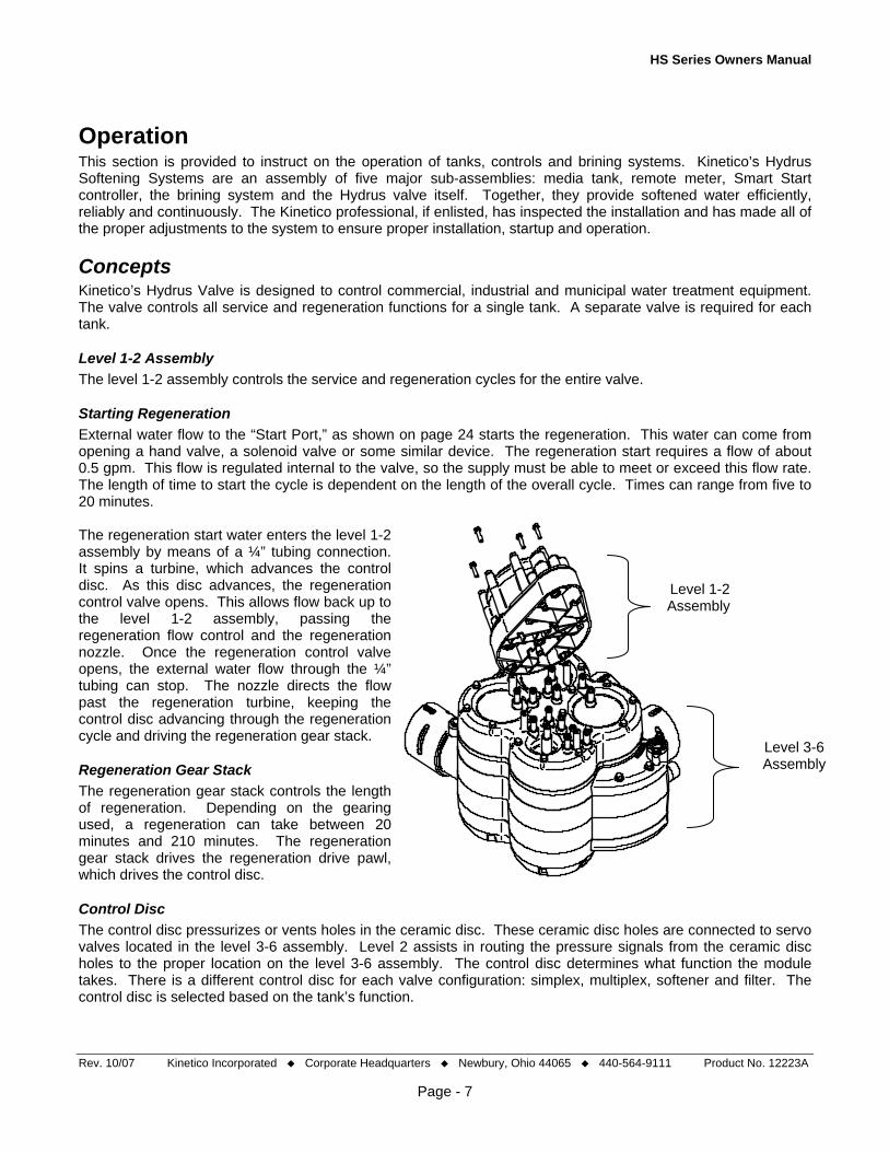
Operation This section is provided to instruct on the operation of tanks, controls and brining systems. Kinetico’s Hydrus Softening Systems are an assembly of five major sub-assemblies: media tank, remote meter, Smart Start controller, the brining system and the Hydrus valve itself. Together, they provide softened water efficiently, reliably and continuously. The Kinetico professional, if enlisted, has inspected the installation and has made all of the proper adjustments to the system to ensure proper installation, startup and operation.
Concepts Kinetico’s Hydrus Valve is designed to control commercial, industrial and municipal water treatment equipment. The valve controls all service and regeneration functions for a single tank. A separate valve is required for each tank.
Level 1-2 Assembly The level 1-2 assembly controls the service and regeneration cycles for the entire valve.
Starting Regeneration External water flow to the “Start Port,” as shown on page 24 starts the regeneration. This water can come from opening a hand valve, a solenoid valve or some similar device. The regeneration start requires a flow of about 0.5 gpm. This flow is regulated internal to the valve, so the supply must be able to meet or exceed this flow rate. The length of time to start the cycle is dependent on the length of the overall cycle. Times can range from five to 20 minutes. The regeneration start water enters the level 1-2 assembly by means of a ¼” tubing connection. It spins a turbine, which advances the control disc. As this disc advances, the regeneration control valve opens. This allows flow back up to the level 1-2 assembly, passing the regeneration flow control and the regeneration nozzle. Once the regeneration control valve opens, the external water flow through the ¼” tubing can stop. The nozzle directs the flow past the regeneration turbine, keeping the control disc advancing through the regeneration cycle and driving the regeneration gear stack.
Rev. 10/07 Kinetico Incorporated Corporate Headquarters Newbury, Ohio 44065 440-564-9111 Product No. 12223A
Page - 7
Regeneration Gear Stack The regeneration gear stack controls the length of regeneration. Depending on the gearing used, a regeneration can take between 20 minutes and 210 minutes. The regeneration gear stack drives the regeneration drive pawl, which drives the control disc.
Level 1-2 Assembly
Level 3-6 Assembly
Control Disc The control disc pressurizes or vents holes in the ceramic disc. These ceramic disc holes are connected to servo valves located in the level 3-6 assembly. Level 2 assists in routing the pressure signals from the ceramic disc holes to the proper location on the level 3-6 assembly. The control disc determines what function the module takes. There is a different control disc for each valve configuration: simplex, multiplex, softener and filter. The control disc is selected based on the tank’s function.
HS Series Owners Manual
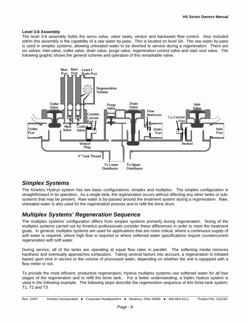
Level 3-6 Assembly The level 3-6 assembly holds the servo valve, valve seats, venturi and backwash flow control. Also included within this assembly is the capability of a raw water by-pass. This is located on level 5A. The raw water by-pass is used in simplex systems, allowing untreated water to be diverted to service during a regeneration. There are six valves: inlet valve, outlet valve, drain valve, purge valve, regeneration control valve and start next valve. The following graphic shows the general scheme and operation of this remarkable valve.
Simplex Systems The Kinetico Hydrus system has two basic configurations: simplex and multiplex. The simplex configuration is straightforward in its operation. As a single tank, the regeneration occurs without affecting any other tanks or sub-systems that may be present. Raw water is by-passed around the treatment system during a regeneration. Raw, untreated water is also used for the regeneration process and to refill the brine drum.
Multiplex Systems’ Regeneration Sequence The multiplex systems’ configuration differs from simplex systems primarily during regeneration. Sizing of the multiplex systems carried out by Kinetico professionals consider these differences in order to meet the treatment goals. In general, multiplex systems are used for applications that are more critical, where a continuous supply of soft water is required, where high flow is required or where softened water specifications require countercurrent regeneration with soft water. During service, all of the tanks are operating at equal flow rates in parallel. The softening media removes hardness and eventually approaches exhaustion. Taking several factors into account, a regeneration is initiated based upon time in service or the volume of processed water, depending on whether the unit is equipped with a flow meter or not. To provide the most efficient, productive regeneration, Hydrus multiplex systems use softened water for all four stages of the regeneration and to refill the brine tank. For a better understanding, a triplex Hydrus system is used in the following example. The following steps describe the regeneration sequence of this three-tank system: T1, T2 and T3.
Rev. 10/07 Kinetico Incorporated Corporate Headquarters Newbury, Ohio 44065 440-564-9111 Product No. 12223A
Page - 8
HS Series Owners Manual
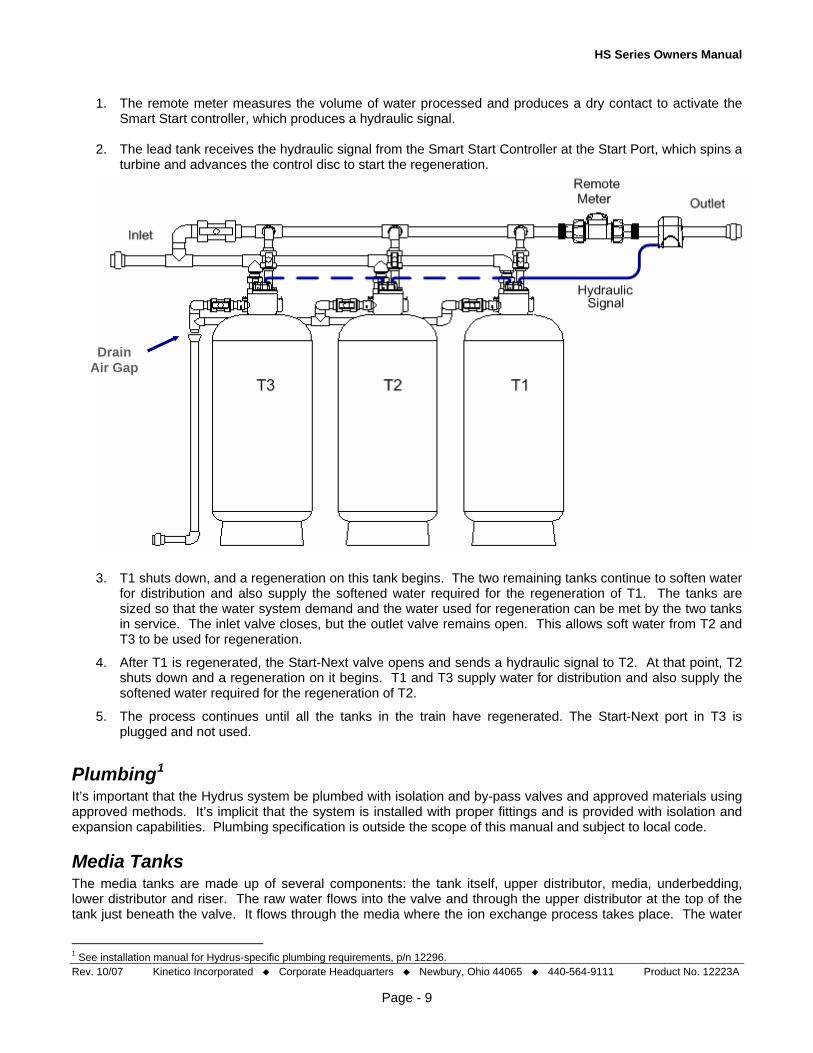
1. The remote meter measures the volume of water processed and produces a dry contact to activate the Smart Start controller, which produces a hydraulic signal.
2. The lead tank receives the hydraulic signal from the Smart Start Controller at the Start Port, which spins a
turbine and advances the control disc to start the regeneration.
Drain Air Gap
3. T1 shuts down, and a regeneration on this tank begins. The two remaining tanks continue to soften water for distribution and also supply the softened water required for the regeneration of T1. The tanks are sized so that the water system demand and the water used for regeneration can be met by the two tanks in service. The inlet valve closes, but the outlet valve remains open. This allows soft water from T2 and T3 to be used for regeneration.
4. After T1 is regenerated, the Start-Next valve opens and sends a hydraulic signal to T2. At that point, T2 shuts down and a regeneration on it begins. T1 and T3 supply water for distribution and also supply the softened water required for the regeneration of T2.
5. The process continues until all the tanks in the train have regenerated. The Start-Next port in T3 is plugged and not used.
Plumbing1 It’s important that the Hydrus system be plumbed with isolation and by-pass valves and approved materials using approved methods. It’s implicit that the system is installed with proper fittings and is provided with isolation and expansion capabilities. Plumbing specification is outside the scope of this manual and subject to local code.
Media Tanks The media tanks are made up of several components: the tank itself, upper distributor, media, underbedding, lower distributor and riser. The raw water flows into the valve and through the upper distributor at the top of the tank just beneath the valve. It flows through the media where the ion exchange process takes place. The water
Rev. 10/07 Kinetico Incorporated Corporate Headquarters Newbury, Ohio 44065 440-564-9111 Product No. 12223A
Page - 9
1 See installation manual for Hydrus-specific plumbing requirements, p/n 12296.

HS Series Owners Manual
is now softened. At the bottom of the media bed, there are two different grades of underbedding. The water flows through the underbedding and into the distributors. Lastly, the water flows up the riser tube and out the valve to service.
Upper Distributor The upper distributor prevents channeling of the inlet stream into the top of the resin bed. A plastic molded distributor is attached to the bottom of the Hydrus valve. Hydrus Valve
Media Upper Distributor High capacity, non-solvent resin is used in Hydrus softeners.
Underbedding In order to ensure proper distribution, minimal pressure drop and to protect the distributors from fouling, two different grades of underbedding may be used. Only fine grade gravel is required for small tanks.
Riser Tube Lower Distributor The lower distributors are of a hub and slotted lateral design. This provides excellent flow distribution through the resin bed. The high surface area of the laterals minimizes pressure loss through the system. On some laterals, there may be blocked off slots, or slots not opened fully. This design assures proper flow and even distribution of the water through the resin bed. The polypropylene construction of the distributor assembly gives it excellent durability.
Distributor
Riser Tube A riser tube is used to connect the lower distributor to the control valve. The riser tube is 2.0” in diameter and cut to length, depending upon the tank size.
Brining System The brining system supplies the saturated brine required to regenerate the softening resin. It is made up of the tank, brine valve and connective plumbing. Conventional Hydrus softening systems employ a separate brine tank for each softener.
Rev. 10/07 Kinetico Incorporated Corporate Headquarters Newbury, Ohio 44065 440-564-9111 Product No. 12223A
Page - 10
tank overflow.
The tanks come in various sizes, typically sized based upon the volume of the media to be regenerated. Larger tanks paired with smaller softeners can extend the time between required maintenance. The tanks are designed to ease the loading of softener grade salt. They’re automatically filled with water to dissolve the solid salt into a saturated liquid form. All brine tanks include an overflow connection to drain an accidental Each brine tank includes a brine valve. It’s used to adjust the volume of brine to be used each regeneration. Each tank, salt setting combination has its own required setting. The setting is made by Kinetico installers and should not require any operational maintenance. Should the brine tank or softener have to be moved or modified in any way, or if the hardness of the influent water changes, an adjustment may be required. A table is on page 13 of this manual that provides instruction on the adjustment of brine valves. Brine Tank

HS Series Owners Manual
Hydrus softeners are generally set up for two different salt dosages. They are set up for either high efficiency or for high capacity. Further, the salt dosage is based upon the configuration of the system, whether simplex or multiplex. Multiplex systems, which all regenerate countercurrently with soft water, are the most efficient. This holds regardless of setting. Efficiencies are easily compared by considering the grains of hardness exchanged versus the number of pounds of salt used per regeneration. The values run from as low as 2,000 grains/pounds salt on a simplex unit adjusted for high capacity to as high as 4,340 grains/pounds salt for a multiplex system adjusted for high efficiency.
lb/ft3 18x65 21x62 24x65 30x72 36x72 42x72
5.0 4,340 4,000 4,100 4,308 4,306 4,304
7.5 3,467 3,200 3,283 3,444 3,444 3,444
10 2,500 2,500 2,500 2,500 2,500 2,500
15 2,000 2,000 2,000 2,000 2,000 2,000
Efficiency, grains/pounds salt
Central Brining Central brining, a less efficient option, is available on Hydrus systems. Election to central brine is typically based on space considerations. More brine tanks take up more space, and larger systems require more salt. A brine tank for each softener can take up a considerable amount of floor space. With larger systems, the salt demand may be high. If a softening system treated water that had 10 grains of hardness and had an average flow rate of 100 gpm, the total amount of salt used each day would be approximately 350 pounds, even at high efficiency. This would be on a Hydrus HS 330s OD. If salt were purchased at a weight of 40 pounds per bag, then approximately nine, 40 pound bags of salt would be required by the system each day. Central brining can be a large brine tank used to supply three small media tanks all the way up to a saturator, used to supply a large high-flow system. A good rule of thumb to use is to calculate the amount of salt used every two weeks. In the example above, that’s 2 ½ tons. If the value is approaching 25 tons, then a saturator that can receive full truck loads should be considered. Buying salt in this way can save time in loading and unloading and money due to buying in bulk.
The Hydrus Valve The Hydrus valve is at the heart of Kinetico’s commercial high-flow systems. It’s a multi-port valve that controls system flow through a single tank. It is designed to link to other Hydrus valves, making expansion to multi-tank configurations uncomplicated. The Hydrus valve is a revolutionary design that allows enormous flexibility in system configuration. The Hydrus uses water pressure to move its internal pistons through service and regeneration cycles. It doesn’t use electrical components; therefore, it is ideally suited for installation in the harshest environments. All regeneration sequences and timing are managed via an on-board hydraulic control disc.
The Hydrus uses a hydraulic start signal to initiate a regeneration. The Hydrus control valve controls the following functions: service, regeneration, brine tank filling and kick-next in the case of multiplex systems. If central brining is employed, the brine tank filling is done by way of a pressurized feed. Regeneration sequences differ between the countercurrent regenerating multiplex systems and co-current regenerating simplex systems. The service cycles are the same. Rev. 10/07 Kinetico Incorporated Corporate Headquarters Newbury, Ohio 44065 440-564-9111 Product No. 12223A
Page - 11

HS Series Owners Manual
Rev. 10/07 Kinetico Incorporated Corporate Headquarters Newbury, Ohio 44065 440-564-9111 Product No. 12223A
Page - 12
System Configuration If an authorized Kinetico professional was not available to ensure a compliant installation, the following guidelines must be followed:
• The system must be complete and parameters set to factory-specified values • The system and installation must comply with federal, state and local laws • The system is not intended to be used for treating water that is microbiologically unsafe or of unknown
quality without disinfection before or after the system • The procedure for sanitizing the softener found on page 25 must be followed after installation or service • The system is intended to be operated within the specified parameters given in this section, including the
following: o The system is intended to be installed indoors, on a level surface where the temperature is
controlled between 35° and 120° F and operated at an effluent pressure of at least 35 psi and an influent pressure not exceeding 125 psi.
Failure to follow the instructions in this manual, or to observe proper installation procedures may void the warranty, cause bodily harm, cause the system to operate improperly or not at all and/or cause damage to the system. Compliance must also be achieved in a modification of the original installation. Consult a Kinetico professional or the appropriate technical documentation if a modification or an alteration is planned or carried out.
Sizing A proper salt setting is dependent upon two factors: the hardness and iron concentration in the feed water, and the desired water softness. There are two different salt settings: the high capacity setting and the high efficiency setting. For a multi-tank system: • The high capacity salt setting should be used if the feed water iron is higher than 1 mg/L. • The high capacity salt setting should be used if the softened water hardness needs to be less than
4 mg/L, • The high efficiency salt setting is used when the soft water can have 4 – 10 mg/L hardness as
calcium carbonate, if the feed hardness is 15 gr/gal or less. • The high efficiency salt setting is used when the soft water can have up to 20 mg/L as CaCO3 when
the feed water hardness is up to 40 gr/gal. A simplex softener: • It should not be used to provide soft water with less than 1 mg/L hardness. • The high capacity salt setting is used to provide soft water with 2 – 9 mg/L hardness. • The high capacity setting should be used when the feed water iron is above 1 mg/L. • The high efficiency setting is used when the desired soft water hardness can be greater than 10
mg/L. As discussed, resin capacity is subject to several factors: the life of the media, additional cation loading not including iron and manganese, and others. Caution can be applied by including a margin of safety to ensure a constant supply of soft water for critical applications. A table is given on page 15.

HS Series Owners Manual
Compensated Hardness Equation:
3
3
CaCOasgr/gallonHardness,dCompensate
manganeseLmg5ironLmg317.1
CaCOasHardness,Lmg
=
×+×+
The equation above is used to determine the compensated hardness. It provides a method for converting iron and manganese into an equivalent hardness.
Brining System Following the chart below, set the brine valve by raising or lowering the float cup:
Rev. 10/07 Kinetico Incorporated Corporate Headquarters Newbury, Ohio 44065 440-564-9111 Product No. 12223A
Page - 13
The following chart provides a guide to the required salt settings for a given tank size. Obtain the number of pounds required from the table below and then use that value to set the height of the float cup.
Salt Dose in lbs (Per Tank) Simplex System Multi-Tank System Tank
Size ft3 of Resin 10-pounds/ft3 15-pounds/ft3 5-pounds/ft3 7.5-pounds/ft3
18x65 5 50-pounds 75-pounds 25-pounds 38-pounds 21x62 6 60-pounds 90-pounds 30-pounds 45-pounds 24x65 8 80-pounds 120-pounds 40-pounds 60-pounds 30x72 12 120-pounds 180-pounds 60-pounds 90-pounds 36x72 18 180-pounds 270-pounds 90-pounds 135-pounds 42x72 26 260-pounds 390-pounds 130-pounds 195-pounds
Float Setting (A) Brine Drum Size Salt Dose,
in Lbs 24x50 30x48 39x60 50x60 25 10.1'' 6.6'' 30 12.1'' 8.0'' 38 15.3'' 10.1'' 6.0'' 40 16.1'' 10.6'' 6.3'' 45 18.1'' 11.9'' 7.1'' 50 20.1'' 13.3'' 7.8'' 60 24.2'' 15.9'' 9.4'' 6.0'' 75 30.2'' 19.9'' 11.8'' 7.5'' 80 21.2'' 12.5'' 8.0'' 90 23.9'' 14.1'' 9.0''
120 31.8'' 18.8'' 12.1'' 135 21.2'' 13.6'' 180 28.2'' 18.1'' 270 27.1''
A
Measure from cups center

HS Series Owners Manual
Venturi Installation 1. Identify the valve body style. The valve body is either a countercurrent or a co-current
style. An arrow, next to the inlet-side venturi, points to a part number. Part number 10906 is the countercurrent valve body and number 10905 is the co-current valve body.
2. Locate the proper venturi cavity for installation. The ports are marked “CO” for simplex systems and “COUNTER” for multi-tank systems.
3. Remove the two screws holding the venturi cover in place. Install the venturi into the venturi cap. Insert venturi & venturi cap into the Level 5A.
The following table identifies which venturi to use in each valve, depending upon tank size whether it’s a simplex or a multiplex system:
Tank Size Simplex, Co-Current Regeneration Multiplex, Countercurrent Regeneration
18 x 65 Brown Orange
21 x 62 Brown Orange
24 x 65 Brown Orange
30 x 72 Brown Blue
36 x 72 Yellow Red
42 x 72 Yellow Gold
Central Brining The following information is given for the conversion to central brining. So long as the brine saturator is providing a continuous, saturated supply of brine, the Hydrus valve will automatically draw the appropriate amount of brine. If a large-scale brine saturator is in place or put in place, advice and parameters for setup and configuration will come from the manufacturer of that product and may vary from manufacturer to manufacturer.
Brine Line Check Valve In systems that are to use one brine tank to supply multiple Hydrus valves, a few provisions are required. First, the normal refill operation of the brine tank must be changed. A ¾” diaphragm-style check valve on the brine line for each Hydrus valve is required. This will prevent other valves from feeding soft water into the brine line when one unit starts drawing brine. A high quality diaphragm check valve is recommended.
Brine Valve Since water will not be automatically added by the Hydrus valve, central brine tanks will require an independent source of refill, which must be from a soft water source. Usually, the common softener effluent line is used and piped to a fill valve and storage tank. This modified refill should allow for the addition of water at the top of the brine tank, allowing maximum contact time with the solid salt. This will reduce the time required to make brine.
Venturi Setting The final change to a normal Hydrus set-up is the modification of the venturi. Based on the central brining option, the venturi selection may change to help accommodate this type of brine system. The venturi installation instructions are outlined above. Based on the following tank sizes, the following venturi should be applied:
18x65 21x62 24x65 30x72 36x72 42x72
Venturi Selection orange orange orange orange orange blue
Rev. 10/07 Kinetico Incorporated Corporate Headquarters Newbury, Ohio 44065 440-564-9111 Product No. 12223A
Page - 14

HS Series Owners Manual
Remote Meter The remote meter monitors the soft water service flow at the control outlet with the meter impeller being the only in-stream moving part. As the turbine turns, its rotation drives a water-lubricated gear train in the dome of the meter. As the output shaft at the top of the meter rotates, the cable connection to the timer clutch assembly turns the meter program wheel on the face of the timer counterclockwise until it reaches the regeneration stop position. Regeneration may occur immediately or on a delayed basis depending upon system requirements. Kinetico modifies the meter from its original configuration to allow it to interface with the Smart Start controller, which directs the Hydrus valve’s operation.
Manual Initiation of a Regeneration Pulse Turn the manual regeneration knob clockwise until the Service Position Indicator dot is in the 3:00 position. This slight movement (approx. 30° advance) of the manual regeneration knob engages the program wheel and starts the reset motor. The black center knob will make one revolution in six minutes.
RegenerationKnob
Important: Always disconnect the meter cable before opening the meter timer assembly.
Setting the Meter 1. Calculate the system’s Gallons Set Point. 2. Set the meter by lifting the inner (clear) dial of the “Meter Program Wheel” until the ‘White Dot’ aligns with
the desired capacity.
Gallons Set Point The gallons set point tables represent the maximum capacity of the Hydrus softeners. The simplex table is based on typical resin capacity. The multiplex tables are based on demonstrated capacity in the softener NSF/ANSI STD 44 testing, which is to a 1.0 gpg leakage point. For demanding application, such as desired hardness less than 3 mg/L or continuous flow, an engineering safety factor should be applied. The following table may serve as a useful guide:
Safety Factor Multiplier Desired Hardness, mg/L CaCO3 Intermittent Service Continuous Service
< 1 0.75 0.60
1 – 3 0.80 0.70
4 – 9 0.85 0.75
10 – 20 0.90 0.80
> 20 0.95 0.85
Rev. 10/07 Kinetico Incorporated Corporate Headquarters Newbury, Ohio 44065 440-564-9111 Product No. 12223A
Page - 15

HS Series Owners Manual
Rev. 10/07 Kinetico Incorporated Corporate Headquarters Newbury, Ohio 44065 440-564-9111 Product No. 12223A
Page - 16
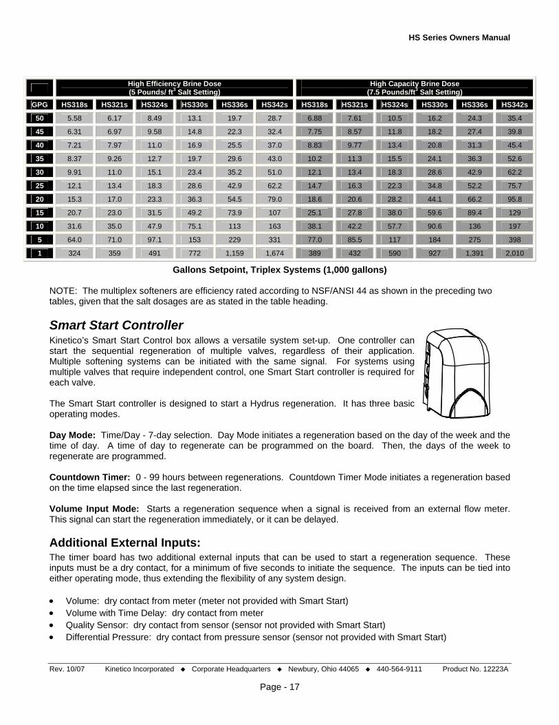
The following tables provide the maximum gallons set point of each system available versus the grains per gallon (gpg).
High Efficiency Brine Dose (10 Pounds/ ft3 Salt Setting)
High Capacity Brine Dose (15 Pounds/ft3 Salt Setting)
GPG HS118s HS121s HS124s HS130s HS136s HS142s HS118s HS121s HS124s HS130s HS136s HS142s
50 2.50 3.00 4.00 6.00 9.00 13.0 3.00 3.60 4.80 7.20 10.8 15.6
45 2.78 3.33 4.44 6.67 10.0 14.4 3.33 4.00 5.33 8.00 12.0 17.3
40 3.13 3.75 5.00 7.50 11.3 16.3 3.75 4.50 6.00 9.00 13.5 19.5
35 3.57 4.29 5.71 8.57 12.9 18.6 4.29 5.14 6.86 10.3 15.4 22.3
30 4.17 5.00 6.67 10.0 15.0 21.7 5.00 6.00 8.00 12.0 18.0 26.0
25 5.00 6.00 8.00 12.0 18.0 26.0 6.00 7.20 9.6 14.4 21.6 31.2
20 6.25 7.50 10.0 15.0 22.5 32.5 7.50 9.00 12.0 18.0 27.0 39.0
15 8.33 10.0 13.3 20.0 30.0 43.3 10.0 12.0 16.0 24.0 36.0 52.0
10 12.5 15.0 20.0 30.0 45.0 65.0 15.0 18.0 24.0 36.0 54.0 78.0
5 25.0 30.0 40.0 60.0 90.0 130 30.0 36.0 48.0 72.0 108 156
1 125 150 200 300 450 650 150 180 240 360 540 780
Gallons Setpoint, Simplex Systems (1,000 gallons)
High Efficiency Brine Dose (5 Pounds/ ft3 Salt Setting)
High Capacity Brine Dose (7.5 Pounds/ft3 Salt Setting)
GPG HS218s HS221s HS224s HS230s HS236s HS242s HS218s HS221s HS224s HS230s HS236s HS242s
50 3.72 4.11 5.66 8.7 13.1 19.1 4.59 5.07 6.97 10.8 16.2 23.6
45 4.20 4.65 6.39 9.9 14.8 21.6 5.17 5.71 7.85 12.2 18.3 26.6
40 4.81 5.31 7.30 11.3 17.0 24.7 5.89 6.52 8.94 13.9 20.9 30.3
35 5.58 6.17 8.47 13.1 19.8 28.7 6.82 7.54 10.4 16.1 24.2 35.1
30 6.61 7.32 10.0 15.6 23.5 34.0 8.05 8.92 12.2 19.0 28.6 41.5
25 8.05 8.92 12.2 19.0 28.6 41.5 9.79 10.8 14.9 23.2 34.8 50.4
20 10.2 11.3 15.5 24.2 36.4 52.7 12.4 13.7 18.8 29.4 44.1 63.9
15 13.8 15.3 21.0 32.8 49.3 71.3 16.7 18.5 25.4 39.7 59.6 86.3
10 21.0 23.3 31.9 50.0 75.1 109 25.4 28.1 38.5 60.4 90.6 131
5 42.7 47.4 64.8 102 153 221 51.4 57.0 77.9 122 184 265
1 216 240 327 515 772 1,116 259 288 393 618 927 1,340
Gallons Setpoint, Duplex Systems (1,000 gallons)
HS Series Owners Manual
High Efficiency Brine Dose (5 Pounds/ ft3 Salt Setting)
High Capacity Brine Dose (7.5 Pounds/ft3 Salt Setting)
GPG HS318s HS321s HS324s HS330s HS336s HS342s HS318s HS321s HS324s HS330s HS336s HS342s
50 5.58 6.17 8.49 13.1 19.7 28.7 6.88 7.61 10.5 16.2 24.3 35.4
45 6.31 6.97 9.58 14.8 22.3 32.4 7.75 8.57 11.8 18.2 27.4 39.8
40 7.21 7.97 11.0 16.9 25.5 37.0 8.83 9.77 13.4 20.8 31.3 45.4
35 8.37 9.26 12.7 19.7 29.6 43.0 10.2 11.3 15.5 24.1 36.3 52.6
30 9.91 11.0 15.1 23.4 35.2 51.0 12.1 13.4 18.3 28.6 42.9 62.2
25 12.1 13.4 18.3 28.6 42.9 62.2 14.7 16.3 22.3 34.8 52.2 75.7
20 15.3 17.0 23.3 36.3 54.5 79.0 18.6 20.6 28.2 44.1 66.2 95.8
15 20.7 23.0 31.5 49.2 73.9 107 25.1 27.8 38.0 59.6 89.4 129
10 31.6 35.0 47.9 75.1 113 163 38.1 42.2 57.7 90.6 136 197
5 64.0 71.0 97.1 153 229 331 77.0 85.5 117 184 275 398
1 324 359 491 772 1,159 1,674 389 432 590 927 1,391 2,010
Gallons Setpoint, Triplex Systems (1,000 gallons) NOTE: The multiplex softeners are efficiency rated according to NSF/ANSI 44 as shown in the preceding two tables, given that the salt dosages are as stated in the table heading.
Smart Start Controller Kinetico’s Smart Start Control box allows a versatile system set-up. One controller can start the sequential regeneration of multiple valves, regardless of their application. Multiple softening systems can be initiated with the same signal. For systems using multiple valves that require independent control, one Smart Start controller is required for each valve. The Smart Start controller is designed to start a Hydrus regeneration. It has three basic operating modes. Day Mode: Time/Day - 7-day selection. Day Mode initiates a regeneration based on the day of the week and the time of day. A time of day to regenerate can be programmed on the board. Then, the days of the week to regenerate are programmed. Countdown Timer: 0 - 99 hours between regenerations. Countdown Timer Mode initiates a regeneration based on the time elapsed since the last regeneration.
Volume Input Mode: Starts a regeneration sequence when a signal is received from an external flow meter. This signal can start the regeneration immediately, or it can be delayed.
Additional External Inputs: The timer board has two additional external inputs that can be used to start a regeneration sequence. These inputs must be a dry contact, for a minimum of five seconds to initiate the sequence. The inputs can be tied into either operating mode, thus extending the flexibility of any system design. • Volume: dry contact from meter (meter not provided with Smart Start) • Volume with Time Delay: dry contact from meter • Quality Sensor: dry contact from sensor (sensor not provided with Smart Start) • Differential Pressure: dry contact from pressure sensor (sensor not provided with Smart Start)
Rev. 10/07 Kinetico Incorporated Corporate Headquarters Newbury, Ohio 44065 440-564-9111 Product No. 12223A
Page - 17

HS Series Owners Manual
Installation Check List The following is a summary of the steps used to set-up and install the Smart Start controller. • Identify Smart Start Components • Install External Power Hook-up • Install Batteries • Set Smart Start Operating Mode • Program the Smart Start Controller • Install Smart Start Box • Attach External Inputs • Attach plumbing to Hydrus Valve
Set the Smart Start Operating Mode
Day Mode/Volume Input Mode or Countdown Mode Day Timer
Day Mode Countdown Mode
Day Timer
The mode of operation is controlled by the top DIP switch. With the DIP switch set to the left, the unit will operate in DAY mode or volume input mode; with the switch set to the right, the unit will operate in countdown mode.
Jumper Position “ON”
Immediate or Delay
Rev. 10/07 Kinetico Incorporated Corporate Headquarters Newbury, Ohio 44065 440-564-9111 Product No. 12223A
Page - 18
If Volume Input Mode is to be used, selection of when the timer will signal a regeneration is required, either immediate or delayed. If the bottom DIP switch is set for IMM, the regeneration will occur immediately. If it’s set for DLY, the regeneration will be delayed to a preset time of day. The Immediate or Delay DIP switch is at the bottom of the group as shown at right. An example of a volume input is a mechanical reset meter.
Programming the Smart Start All programming functions for the Smart Start are controlled either through the placement of the DIP switches or by the pushbutton interface. Programming the Smart Start through the pushbutton interface is simple. When pushing the button, the current value for each button is displayed. If the button is held for two seconds, the value will increase one digit at a time. When released, the value is recorded in the system’s memory. To set any input, simply hold the button in until the appropriate value is displayed, then release. If desired value is passed, the cycle will repeat.
Day
TIME
REGEN
KICK
CHLOR
DLY IMM Immediate Mode
DLY IMM Delay Mode

HS Series Owners Manual
Pushbuttons
Button Countdown Mode Range Day Mode Volume Input Mode Range
Day Not used NA Current day of week (Sunday = 1) Not used 1 - 7
Time Hours until next
regeneration, for display only – no set point
0 - 99 Current time of Day (24 hour clock)
Current time of day used in delay mode 0 - 23
Regen Regen Frequency (in Hours) 0 - 99 Time of day to start a
regeneration
Time to start a regeneration used in
day mode 0 - 23
Kick Duration to open solenoid valve in minutes (set to 10) 0 - 20
Duration to open solenoid valve in minutes
(set to 10)
Duration to open solenoid valve in
minutes 0 - 20
Chlor Not Used NA Not Used Not used NA
DIP Switches In addition to setting the operating mode, the DIP switches are also used in the DAY mode to identify which days of the week the unit should regenerate. These additional switches are only used in the DAY mode. In the countdown timer mode or volume input mode, all of the day switches should be at the disabled side.
Rev. 10/07 Kinetico Incorporated Corporate Headquarters Newbury, Ohio 44065 440-564-9111 Product No. 12223A
Page - 19
Examples:
Test Mode To verify that all the DIP switches are set properly, the unit can be placed in a test mode. To enter the test mode, first disconnect the power. This can be done by unplugging the external power supply and disconnecting the battery pack at the circuit board via the quick connectors. If no external power supply is used, then disconnecting the battery pack will de-energize the unit. Next, reconnect power, while holding down the REGEN and CHLOR buttons. After the display illuminates, release the buttons. The unit is now in test mode, with various segments of the display LED energized, based on DIP switch settings. To return to the regular operating mode, simply cycle the power to the board.
Day
TIME
REGEN
KICK
CHLOR
2 Sunday 3 Monday 4 Tuesday 5 Wednesday 6 Thursday 7 Friday 8 Saturday
Enabled Disabled
2 3 4 5 6 7 8
Sunday Regeneration
2 3 4 5 6 7 8
Tuesday and Friday Regeneration
2 3 4 5 6 7 8
Daily Regeneration

HS Series Owners Manual
Test Mode Results The following are the illuminated LED’s, based on DIP switch settings:
Rev. 10/07 Kinetico Incorporated Corporate Headquarters Newbury, Ohio 44065 440-564-9111 Product No. 12223A
Page - 20
Countdown Mode (no LED's Energized) Day Mode / Volume Mode
Sunday Monday Tuesday Wednesday Thursday Friday Saturday
Additional Smart Start Features Low Battery Alarm Condition – This Smart Start board is equipped with a low battery alarm circuit. When the voltage at the solenoid, not at the battery pack, is less than 4.3 VDC, the low battery alarm turns on. The red low battery light blinks once every five seconds to denote a low battery. Change the battery at this time. Low Battery Shutdown Condition – The Smart Start board monitors the low battery condition. When the voltage at the solenoid is less than 4.1 VDC, the system enters a shutdown mode and does not attempt to regenerate. This prevents the Smart Start board from opening the solenoid, and not being able to close it. The low battery red LED light blinks once every two and a half seconds to denote the system is in a low battery shutdown condition. Change the battery at this time.
Battery Change Out - To change the battery, press all five push buttons (one after the other) to record the current parameters to non-volatile memory. Then remove the old batteries and put in the new ones. Check your parameters to ensure the proper values are shown and have been correctly kept. A lithium ion battery is recommended for maximum battery life.
Manual Forced Regeneration A regeneration is forced by pressing and holding the TIME and REGEN push buttons together for five seconds. “Fr” is displayed to denote the manual regeneration start. Regularly scheduled regenerations will still occur. The solenoid valve opens for the programmed KICK time. If the unit is in a lockout (minimum regeneration frequency is five hours), then the display will show “FL.” This denotes that a regeneration will occur at the end of the lockout period.
Manual Close Solenoid The solenoid is manually closed by pressing and holding the TIME and DAY push buttons together for five seconds. “CL” is displayed to denote the solenoid closed operation. One pulse is heard as the Smart Start board closes the solenoid.
Power Up Upon application of power, all lamps are turned on. Then the display shows the program revision number. Finally, the battery voltage at the solenoid terminals is sensed and displayed.
System Lockout The Smart Start will allow a regeneration once every five hours. When a regeneration cycle starts, a lockout time will also begin to count down from five hours. During this period, requests for regeneration will be stored and started at the end of the lockout period. Only one request will be stored to memory during the lockout period. To display the time remaining in the lockout period in hours, press the REGEN and KICK buttons.

HS Series Owners Manual
Rev. 10/07 Kinetico Incorporated Corporate Headquarters Newbury, Ohio 44065 440-564-9111 Product No. 12223A
Page - 21
Additional Inputs Additional, external inputs can be used to further configure the operation of the Smart Start. For each of these signals, it is important to only use dry, non-power contacts. Applying external voltage to the Smart Start board through these inputs will damage the board.
+ - Power
Delta P
Regen
Reset
Alarm
Name Description Spec Result Time to make
Alarm Closed contact from external salt alarm Dry Contact Yellow lamp blinks 10 minutes
Reset Not Used Dry Contact Not used N/A
Regen Closed contact from external
mechanical meter based on meter’s set-point
Dry Contact Starts a Regen or BW sequence
5 seconds off after 10 min.
Delta P Closed contact from external differential pressure switch Dry Contact Starts a Regen or BW
sequence 15 min.
12 VDC External power connection 12 VDC + -
Supplies power to circuit board N/A

HS Series Owners Manual
System Maintenance Kinetico has engineered the Hydrus system to provide quality water without requiring extensive maintenance. Minor, routine maintenance is recommended to keep the softener working properly. No special tools are required for system repairs or maintenance. If the system is completely cut off from power, whether hydraulic or electrical, the system does not require resetting. It picks up where it left off. These are some of the many benefits built into all Hydrus Softening Systems to ensure trouble-free ownership. Not only is the unit easy to maintain, it’s built tough and has been extensively tested. The multiplex systems conform to NSF/ANSI1 Standard 44 for the specific performance claims as verified and substantiated by test data. The battery of third-party testing includes:
• Materials of construction – verifying they are non-leaching and able to maintain surface integrity in operation
• Structural performance – Verifying working pressure, burst testing, cycle testing, non-hazardous, electrical safety, waste segregation and verification of chemical and mechanical performance and operation
• Mandatory testing of elective claims – verifying efficiency, water use, required operating pressures and exchange capacity
• Verification of manufacturers promotional materials and the inclusion of specific information in operational and maintenance instructions
Adding Regenerant Prior to installation of the Hydrus softener, an estimated salt usage calculation should be carried out. Based upon this calculation and other factors, the system has been set up to run at high efficiency or high capacity. These operational parameters can be fine-tuned after installation.
Rev. 10/07 Kinetico Incorporated Corporate Headquarters Newbury, Ohio 44065 440-564-9111 Product No. 12223A
Page - 22
It’s important to select the right salt for regeneration to keep the system operating optimally. Only high-quality, softener grade salt should be used. A minimum purity of 99.8 percent salt is recommended. Manufacturers of softener salt have particular formulations to ensure trouble-free softening. Some features and benefits:
• Uniquely shaped for extra hardness • Virtually 100 percent water soluble, minimizing brine tank
clean out • Helps prevent mushing, bridging and channeling • Designed to keep softeners clean and trouble-free
The frequency of salt replenishment is based upon usage and size brine tank in use. Simply fill the brine tank with salt until the level reaches just below the structure that houses the float assembly. The following table shows the capacities of each available brine drum, along with other information. If a softening system is to be reconfigured, careful consideration must be given to brine drum capacities. A larger, expanded system may require additional brine storage capacity in order to operate properly.
Salt Fill Line
1 NSF/ANSI 44 – 2004, “Residential Cation Exchange Water Softeners,” NSF International Standard/American National Standard

HS Series Owners Manual
Rev. 10/07 Kinetico Incorporated Corporate Headquarters Newbury, Ohio 44065 440-564-9111 Product No. 12223A
Page - 23
24” x 50” 30” x 48” 39” x 60” 50” x 60”
Tank Composition Polyethylene Polyethylene Polyethylene Polyethylene
Brine Valve Material Polypropylene Polypropylene Polypropylene Polypropylene
Brine Well Size 6” 6” 6” 6”
Overflow Protection ½” ½” ½” ½”
Brine Valve Connections ½” ½” ½” ½”
Salt Capacity 850 pounds 1,350 pounds 1,500 pounds 4,500 pounds
Volume Capacity 80 gallons 147 gallons 260 gallons 425 gallons
Maximum Brine Dosing 75 pounds 136 pounds 180 pounds 270 pounds
Empty Weight 45 pounds 80 pounds. 80 pounds. 110 pounds
Maximum Brine Dosing
5 pounds/ft3 15 ft3 27 ft3 36 ft3 54 ft3
7.5 pounds/ft3 10 ft3 18 ft3 24 ft3 36 ft3
10 pounds/ft3 8 ft3 14 ft3 18 ft3 27 ft3
15 pounds/ft3 5 ft3 9 ft3 12 ft3 18 ft3
Brine Tank Specifications IMPORTANT: Never use rock salt in the system as it contains impurities that can interfere with performance.
Brine Drums A combination salt storage and brine production tank, this unit is manufactured of corrosion-resistant, rigid polyethylene. The brine tank has an internal brine well chamber to house the brine valve assembly. The brine float assembly allows for adjustable salt settings and provides for a shut-off to the brine refill. The brine tank includes a safety overflow connection to be plumbed to a suitable drain. In most cases, one brine tank is required for each media tank. This is because multiplexed systems regenerate sequentially. Once the first tank completes a regeneration, the regeneration of the second tank immediately follows. This brings two challenges to a brining system. One, the system must have sufficient capacity to provide saturated brine to each of the tanks in the sequence. Two, the brining system must retain a constant concentration of brine. Since the previous tank in the sequence replenishes the brine tank, it changes the concentration of the brine. Although a brine tank may have sufficient capacity to brine several tanks, since the concentration of the brine solution in that tank changes, each media tank requires its own brine tank. Due to these challenges, a change in configuration is required if brining is to be carried out centrally, and the existing Hydrus system is configured with each media tank paired to a brine tank. Likewise, a change in configuration is required if brining is to be carried out by pairing, and the existing Hydrus system is configured for central brining.

HS Series Owners Manual
Remote Meter A remote meter is installed to measure the volume of processed water. Once the set volume is reached, a signal is interpreted by the Smart Start controller, which in turn sends a hydraulic signal to the lead tank to initiate a regeneration. A remote meter can be used with both simplex and multiplex systems. For multiplex systems, the meter is located on the combined system outlet.
Manual Regeneration If the salt storage tank runs out of salt, a manual regeneration of the unit is required after adding salt. An automatic regeneration will eventually occur, but hard water will enter the water system until a regeneration occurs. There are several ways to force the Hydrus valve to regenerate:
Rev. 10/07 Kinetico Incorporated Corporate Headquarters Newbury, Ohio 44065 440-564-9111 Product No. 12223A
Page - 24
Battery Connection Terminal Red positive wire is on top of connector, and the connector is keyed. Note: Only use Kinetico battery pack.
Battery Pack Press into mid-wall section. Note: the fit is tight to keep the battery in place.
1. Advance the Remote Meter as described on
page 17. 2. Manually advance Level 1-2 of the Hydrus
valve, as shown at right and described: a. To manually regenerate the system, use
a ¼” nut driver to turn the small, hex-shaped “Override Actuator.” Slowly turn counter-clockwise until the actuator has advanced the “Indicator” arrow to the “BRINE” position, about 10°. At this point, the flow of water will be audible. This indicates a successful regeneration initiation has occurred. If water flow is not heard, contact a Kinetico professional.
Start Port
Regeneration drive water drain
Override Actuator
Indicator
Start Next Port
3. A regeneration can also be forced by following the procedure described on page 22 by using the Smart Start controller. The procedure manually opens the solenoid valve, which in turn directs a flow of water to the Start Port of the Hydrus valve.
Battery Replacement Insert the battery pack into the mid-wall section to hold the batteries. Plug the keyed battery connector into the two-terminal port on the inside of the circuit board labeled “BAT+POWER.”

HS Series Owners Manual
Rev. 10/07 Kinetico Incorporated Corporate Headquarters Newbury, Ohio 44065 440-564-9111 Product No. 12223A
Page - 25
Softener Sanitation Procedure It’s necessary to sanitize the system prior to its first use. It may also become necessary during the lifetime of the softener to disinfect the system. This procedure should be carried out when new resin is installed, any time a significant break in the system occurs and a contaminant may have entered the system, or if the water supply has been in some way temporarily contaminated. 1. Regenerate both tanks of the water conditioning unit with sodium chloride (salt). Use a clean grade of salt
appropriate for use with water treatment equipment. Do NOT use rock salt. 2. Mix one fluid ounce of unscented household bleach per four gallons of clean/soft water. This should make a
100 ppm solution. A table is provided below, which gives the gallons of disinfectant required for each system.
Tank Size 18x65 21x62 24x65 30x72 36x72 42x72 Tank Volume, ft3 8.3 11 13.4 25 35.3 46.1 Solution Required per Tank, gallons 4.5 6.0 7.3 13.6 19.2 25.1 5.25% Sodium Hypochlorite Required, ounces 1.1 1.5 1.8 3.3 4.7 6.1
3. Disconnect the brine line, and put the ½” tube into the container holding the bleach mixture from the step
above. 4. Put the unit into brine draw on one tank. 5. Draw the mixture until a strong bleach odor is detected (smelled or tested) in the drain line. This procedure
should produce approximately 20 ppm in the mixed solution. 6. Make sure the system is isolated from service. Advance the control disc to the service position, and allow the
unit to stand for 30-60 minutes. The colder the water, the longer the stand time should be. 7. Reconnect the brine line (½” tube) to the brine tank, and backwash each tank of the softener two times.
HS Series Owners Manual
Rev. 10/07 Kinetico Incorporated Corporate Headquarters Newbury, Ohio 44065 440-564-9111 Product No. 12223A
Page - 26
Troubleshooting Kinetico has identified 11 problems familiar to softening systems. This troubleshooting guide is intended to serve as a useful diagnostic tool in solving more common, easy to determine problems. If the problem is not shown below, a call to the local Kinetico professional should be helpful. Kinetico will try to assist over the phone and may send out a service professional. Troubleshooting....................................................................................................................... 26
Frequent Regeneration ....................................................................................................................................... 27 The customer is not familiar with Hydrus unit operation ............................................................................................................................27 High water usage .......................................................................................................................................................................................27
Hard Water .......................................................................................................................................................... 27 Water meter not working ............................................................................................................................................................................27 The unit will not go into automatic regeneration.........................................................................................................................................27 No vacuum in brine position .......................................................................................................................................................................28 Short salting ...............................................................................................................................................................................................28 Bridged salt in the brine drum ....................................................................................................................................................................28 The by-pass is open...................................................................................................................................................................................29 The by-pass is leaking................................................................................................................................................................................29 Raw water ..................................................................................................................................................................................................29 Distributor tube O-ring ................................................................................................................................................................................29 Brine drum does not refill or overfills ..........................................................................................................................................................29 Fouled resin................................................................................................................................................................................................29 Wrong venturi .............................................................................................................................................................................................30
High Salt Consumption........................................................................................................................................ 30 Regenerates too often................................................................................................................................................................................30 Water level in the brine drum is too high....................................................................................................................................................30
Iron Bleed Through.............................................................................................................................................. 30 Customer plumbing ....................................................................................................................................................................................30 The salt setting is not set properly for current raw water conditions ..........................................................................................................30 The iron may be ferric iron .........................................................................................................................................................................30 The customer's plumbing may include a galvanized pressure tank ...........................................................................................................31
Leaks................................................................................................................................................................... 31 Water leaks from any of the assembly levels.............................................................................................................................................31 Water feed pressure is too high (125 psi maximum)..................................................................................................................................31 Water leaks at the base..............................................................................................................................................................................31
No Water to Service ............................................................................................................................................ 31 Multi-tank system with overlapping unit regeneration ................................................................................................................................31
Pressure Loss ..................................................................................................................................................... 32 Reduced pressure entering the unit ...........................................................................................................................................................32 The upper and/or lower distributors are plugged .......................................................................................................................................32
Salty Treated Water ............................................................................................................................................ 32 Restricted drain line....................................................................................................................................................................................32 Low water pressure ....................................................................................................................................................................................32 The backwash flow control is plugged .......................................................................................................................................................32 The drain is extremely long or placed higher than 8 feet above the Hydrus valve.....................................................................................33 The upper distributors are plugged ............................................................................................................................................................33 Water level in the brine drum is too high....................................................................................................................................................33
Taste, Color and/or Odor..................................................................................................................................... 33 Treated water has a metallic or iron taste ..................................................................................................................................................33 Treated water has chlorine odor and/or taste ............................................................................................................................................33 Treated water has a yellow tint...................................................................................................................................................................33 Treated water has an odor (hot water only) ...............................................................................................................................................33
Unit Sticks in Cycle.............................................................................................................................................. 34 The unit sticks in regeneration or backwash cycle.....................................................................................................................................34
Water Running to Drain....................................................................................................................................... 34 The balance piston O-ring is not seated ....................................................................................................................................................34 Bad control disc..........................................................................................................................................................................................34 Valve not sealing – drain purge control ......................................................................................................................................................35 Stem or piston quad rings not sealing........................................................................................................................................................35 Low water pressure ....................................................................................................................................................................................35 Plugged level 1...........................................................................................................................................................................................35

HS Series Owners Manual
Rev. 10/07 Kinetico Incorporated Corporate Headquarters Newbury, Ohio 44065 440-564-9111 Product No. 12223A
Page - 27
Beginning with “Frequent Regeneration,” possible reasons for the complaint are given and the corresponding solutions.
Frequent Regeneration
The customer is not familiar with Hydrus unit operation
If customer previously owned an electric unit with timer based regeneration, they may not realize that Hydrus units can regenerate at any time of the day or night.
Explain to the customer how the Hydrus
softener works Emphasize that regeneration is controlled
by the measurement of water use rather than on an arbitrary timed basis
High water usage
The customer may be using more water than he realizes Obtain a water-bill (if customer is on a city
water system) and determine how much water should be used
Hard Water
Water meter not working
No water meter signal Replace meter
Check cable running from meter to timer
Hydraulic signal being interrupted from starter control box
Troubleshoot control box
Minimum flow rate for 2” meter is 3 gpm and 7 gpm for a
3” meter
Identify cause of low flow rate and reduce
capacity set-point to compensate for non-metered low flow
Meter wiring not correct to Smart Start
Check wiring and continuity between meter
and Smart Start control box
The unit will not go into automatic regeneration
Meter or timer not properly programmed See set-up and troubleshooting for these
devices
Start solenoid malfunctioning
Repair or replace solenoid

HS Series Owners Manual
Rev. 10/07 Kinetico Incorporated Corporate Headquarters Newbury, Ohio 44065 440-564-9111 Product No. 12223A
Page - 28
Smart Start pre-filter clogged
Clean or replace pre-filter cartridge
Lock out time engaged Controller requires five hours between
regenerations
Wrong Mode of Operation on Smart Start
Check first DIP switch: Left for DAY mode
and right for COUNTDOWN mode
No vacuum in brine position
Plugged venturi
Clean
Incorrect control disc
Match control disc to regeneration type:
White – Multiplex systems Tan – Simplex systems
Plugged backwash flow control
Clean out backwash flow control
Plugged drain line
Clean out drain line
Broken venturi
Replace
Short salting
Plugged venturi – brine tank not refilling properly
Clean venturi
Brine valve not set properly
Refer to manual for correct brine valve
settings
Salt mushed
Clean salt drum
Bridged salt in the brine drum
Salt has solidified in the drum Carefully move the salt around to break up
the mass of solidified salt Use salt with Dextrin binder
HS Series Owners Manual
Rev. 10/07 Kinetico Incorporated Corporate Headquarters Newbury, Ohio 44065 440-564-9111 Product No. 12223A
Page - 29
The by-pass is open
An open by-pass allows water to flow around the system without any treatment at all
Close the by-pass
All simplex units incorporate an internal by-pass. While
the unit is in regeneration, this by-pass is open. Do not sample for quality while a simplex unit is in regeneration.
Sample during service for a simplex system,
not regeneration
The by-pass is leaking
This can be determined by testing the water at a soft water tap. Shut off unit, disconnect the brine line, add a shut-off valve, turn unit on and test water at fitting. Water that tests soft at the brine fitting and hard at the tap indicates a by-pass is leaking.
Repair or replace the by-pass
Raw water
Raw water statistics have changed
Retest raw water and reprogram meter or
timer as needed
Distributor tube O-ring
Distributor tube o-ring rolled or cut
Replace O-ring
Brine drum does not refill or overfills
The brine valve is set incorrectly
Set the brine valve according to instructions
on the brine valve installation sheet in the owner's pack or tech manual
The brine valve is non-conforming
Replace the brine valve
The brine drum is dirty
Clean out the brine drum
The venturi nozzle is plugged
Clean out the venturi
Fouled resin
Obtain sample for analysis
Determine proper cleaning procedure

HS Series Owners Manual
Rev. 10/07 Kinetico Incorporated Corporate Headquarters Newbury, Ohio 44065 440-564-9111 Product No. 12223A
Page - 30
Wrong venturi
Verify venturi selection
Replace with proper venturi
High Salt Consumption
Regenerates too often
See the section entitled Frequent Regeneration
See the section entitled Frequent
Regeneration
Water level in the brine drum is too high
The brine valve is set wrong or non-conforming Verify the brine valve setting. Replace non-
conforming brine valve
The brine valve or the brine drum is dirty
Clean brine valve and drum
The brine valve leaks.
Tighten the connectors on the brine valve
Iron Bleed Through
Customer plumbing
Previous iron buildup inside existing plumbing after the water softener
Verify that customer plumbing is the
problem by testing the water quality at the brine fitting with water running
The salt setting is not set properly for current raw water conditions
The composition of raw water can change with time Check the hardness and iron content of
raw water. Set the brine valve for current raw water conditions
The iron may be ferric iron
Ferric iron is not removable by ion exchange Verify by using the demo softener to
determine if iron is removable by ion exchange. Add additional equipment if needed

HS Series Owners Manual
Rev. 10/07 Kinetico Incorporated Corporate Headquarters Newbury, Ohio 44065 440-564-9111 Product No. 12223A
Page - 31
The customer's plumbing may include a galvanized pressure tank
A galvanized pressure tank will create oxidized iron Replace the galvanized pressure tank with
a bladder-style pressure tank
Leaks
Water leaks from any of the assembly levels
Valve screws are not tightened Depressurize the unit and tighten the Main
Valve screws. 80 inch-pounds
One of the seals between assembly levels is pinched or
missing
Replace the non-conforming seal
One of the screw holes is stripped or cracked
Replace the level
There is a crack on the seal area near a screw hole
Replace the level
Water feed pressure is too high (125 psi maximum)
The pressure regulator is broken
Replace pressure regulator
Water leaks at the base
The base is not tightened properly
Tighten base
The O-ring on the base is pinched or missing
Replace base O-ring
No Water to Service
Multi-tank system with overlapping unit regeneration
For a duplex, overridden regeneration start signal while one tank is still in regeneration
Open system by-pass to allow water to
outlet side of valves. Manually advance valve to service position. This will allow valves to reset. One valve can then be manually advanced to original regeneration stage, if desired

HS Series Owners Manual
Rev. 10/07 Kinetico Incorporated Corporate Headquarters Newbury, Ohio 44065 440-564-9111 Product No. 12223A
Page - 32
Multiple regenerations prior to completion of regeneration
lock-out
Open by-pass to allow unit to cycle
Manual regeneration override while another unit was
regenerating
Open by-pass to allow unit to cycle
Stuck regeneration signal
Check for debris in solenoid valve
Pressure Loss
Reduced pressure entering the unit
The pre-filter is clogged
Replace the clogged pre-filter
The upper and/or lower distributors are plugged
Foreign matter from the input lines is accumulating in the distributors
Clean the distributors. Add a pre-filter to
eliminate the foreign matter before it enters the unit
Salty Treated Water
Restricted drain line
The drain is kinked or clogged
Clear any obstructions. Make sure that the
drain line flows smoothly and unrestricted
Low water pressure
The unit should not see water pressure drop below 30 psi on the outlet at any time. During the backwash portion of the regeneration cycle, it must hold at least 30 psi or the brine may not rinse out completely
Test the outlet pressure with the unit in
backwash and at high flow. Measure the pressure by placing a gauge on the brine fitting. Raise pressure if below 30 psi
The backwash flow control is plugged
Without enough backwash flow to the drain, the unit cannot wash all the salt from the media tanks
Clean the backwash flow control
Check hole size
HS Series Owners Manual
Rev. 10/07 Kinetico Incorporated Corporate Headquarters Newbury, Ohio 44065 440-564-9111 Product No. 12223A
Page - 33
The drain is extremely long or placed higher than 8 feet above the Hydrus valve
Such drain runs can put back-pressure on the unit and restrict the drain flow
Locate a closer drain or use a larger
diameter drain line
The upper distributors are plugged
Foreign material that finds its way into the media tanks may be collected around the upper distributors during backwash, clogging them
Clean upper distributors
Install a pre-filter
Water level in the brine drum is too high
The brine valve is set wrong or non-conforming
Verify the brine valve setting. Replace non-
conforming brine valve
Taste, Color and/or Odor
Treated water has a metallic or iron taste
See the section entitled "Iron Bleed-Through"
Treated water has chlorine odor and/or taste
This is due to heavily chlorinated raw city water
Install a carbon filter
Treated water has a yellow tint
The raw water may have traces of tannins present
See the section entitled "Iron Bleed-Through"
Contact Technical Support
Treated water has an odor (hot water only)
The magnesium rod in hot water tanks can cause a reaction that gives off an odor of rotten eggs
Remove this rod from the hot water heater.
An alternative rod may be installed
HS Series Owners Manual
Rev. 10/07 Kinetico Incorporated Corporate Headquarters Newbury, Ohio 44065 440-564-9111 Product No. 12223A
Page - 34
Unit Sticks in Cycle
The unit sticks in regeneration or backwash cycle
The regeneration flow path is plugged at the regeneration nozzle or flow control
Clean the regeneration flow path
The regeneration drive pawl and/or spring is weak or
broken
Replace the regeneration drive pawl
There is a damaged tooth on the control disc
Replace the control disc
The eccentric pinion is worn
Replace the eccentric pinion
(snap fit)
Drain line from L-1 restricted
Clean drain line
Poor outlet pressure (<30 psi.)
Increase pressure to system, or further
reduce flow rate of system by the use of a flow control at the outlet of the system
Solenoid valve of Smart Start controller stuck in open position
Clean solenoid valve or replace
Water Running to Drain Verify that the leak is in fact coming from the L-1 Level or the main drain by removing the line from the L-1 Level drain. If no leak is detected, go to “Valve not sealing – drain purge control”
The balance piston O-ring is not seated
Water will leak past an improperly seated balance piston O-ring and out the drain
Replace worn or non-conforming O-ring
Bad control disc
A scored control disc will allow a fast drip to a pencil-sized stream to flow through the drain
Replace the control disc

HS Series Owners Manual
Rev. 10/07 Kinetico Incorporated Corporate Headquarters Newbury, Ohio 44065 440-564-9111 Product No. 12223A
Page - 35
Valve not sealing – drain purge control
Foreign matter under the seals will not allow them to seat properly
Disassemble and remove the foreign
matter from seals
Chlorine damage to seal
Replace seal (and valve if it is an over
molded seal)
Stem or piston quad rings not sealing
Foreign matter under the seals will not allow them to seat properly
Disassemble and remove the foreign
matter from seals
Chlorine damage to seal
Replace seal (and valve if it is an over
molded seal)
Low water pressure
If the water pressure is less than 30 psi at the brine fitting, the system may not operate properly
Increase water pressure
Plugged level 1
Check level I drain is free from obstructions Clean level 1
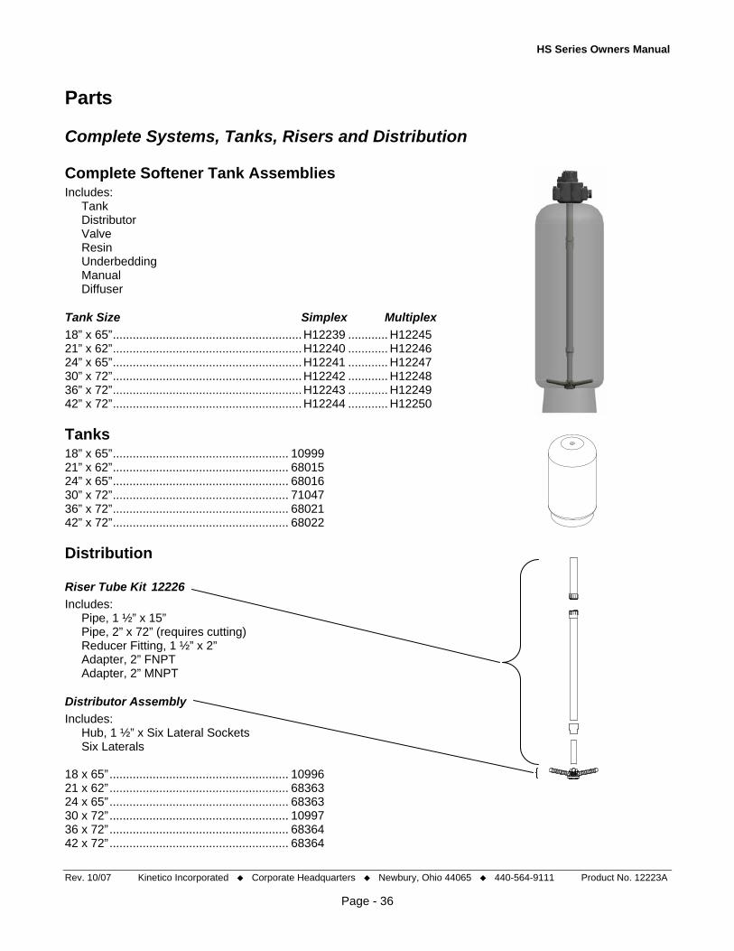
HS Series Owners Manual
Parts
Complete Systems, Tanks, Risers and Distribution
Complete Softener Tank Assemblies Includes: Tank Distributor Valve Resin Underbedding Manual Diffuser
Tank Size Simplex Multiplex 18” x 65”.........................................................H12239 ............ H12245 21” x 62”.........................................................H12240 ............ H12246 24” x 65”.........................................................H12241 ............ H12247 30” x 72”.........................................................H12242 ............ H12248 36” x 72”.........................................................H12243 ............ H12249 42” x 72”.........................................................H12244 ............ H12250
Tanks 18” x 65”..................................................... 10999 21” x 62”..................................................... 68015 24” x 65”..................................................... 68016 30” x 72”..................................................... 71047 36” x 72”..................................................... 68021 42” x 72”..................................................... 68022
Distribution
Rev. 10/07 Kinetico Incorporated Corporate Headquarters Newbury, Ohio 44065 440-564-9111 Product No. 12223A
Page - 36
Riser Tube Kit 12226 Includes: Pipe, 1 ½” x 15” Pipe, 2” x 72” (requires cutting) Reducer Fitting, 1 ½” x 2” Adapter, 2” FNPT Adapter, 2” MNPT
Distributor Assembly Includes: Hub, 1 ½” x Six Lateral Sockets Six Laterals 18 x 65”...................................................... 10996 21 x 62”...................................................... 68363 24 x 65”...................................................... 68363 30 x 72”...................................................... 10997 36 x 72”...................................................... 68364 42 x 72”...................................................... 68364

HS Series Owners Manual
The Hydrus Valve Includes valve manual
Complete Valves Hydrus, Soft, Multi-Tank, 18-24..................H12194 Hydrus, Soft, Multi-Tank, 30-42..................H12189 Hydrus, Soft, Simplex, 18-24......................H12198 Hydrus, Soft, Simplex, 30-42......................H12202
Levels 1 and 2
Screws (#10 x 1.5") (QTY 8 for Cap) ...................................10734 Actuator ................................................................................12303 Drive Pawl ......................................................................... 10980A Cap Filter, Single or Multiplex .............................................. 12216A Softener, Multi –Tank, Countercurrent ......................... 12217A Softener, Simplex, Co-Current ..................................... 12218A O-ring Indicator.......................................................................1460 Indicator............................................................................. 10927A Balance Piston........................................................................9260 Balance Piston O-ring ............................................................1070 Balance Piston Spring ............................................................5448 Cap O-ring 045.....................................................................10928 Control Disc Multi-Tank Softener (WHITE) ....................................... 10910B Single Tank Softener (TAN) .........................................10912C Regen Eccentric Pin.............................................................10949 Drive Pawl ......................................................................... 10980A Filter Disc L-1 SS..................................................................10781 Level 1 Screw (QTY 4 for Level 1) .........................................1010 Level 1 Screw Quad Ring.....................................................10981 Regeneration Drive Pawl Assembly.................................. 10980A Level1 (w/inserts), Ceramic, Stem Gear ........................... 10901A Control Disc Pin......................................................................1023 Flow Control (0.4 gpm).........................................................12314 Seal Level1........................................................................ 10923A Level 2 ............................................................................... 10903A Screw (Level 2 to Level 1) (QTY 8)......................................10734
Rev. 10/07 Kinetico Incorporated Corporate Headquarters Newbury, Ohio 44065 440-564-9111 Product No. 12223A
Page - 37
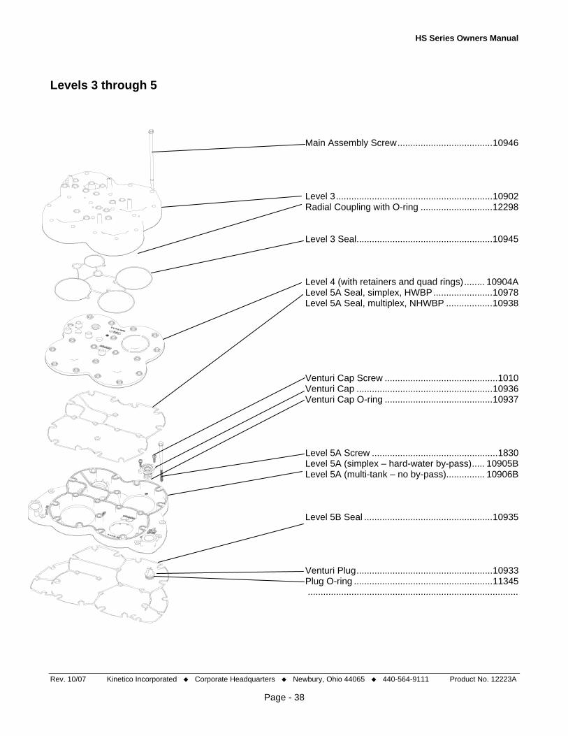
HS Series Owners Manual
Levels 3 through 5
Main Assembly Screw.....................................10946 Level 3.............................................................10902 Radial Coupling with O-ring ............................12298 Level 3 Seal.....................................................10945 Level 4 (with retainers and quad rings)........ 10904A Level 5A Seal, simplex, HWBP.......................10978 Level 5A Seal, multiplex, NHWBP ..................10938 Venturi Cap Screw ............................................1010 Venturi Cap .....................................................10936 Venturi Cap O-ring ..........................................10937 Level 5A Screw .................................................1830 Level 5A (simplex – hard-water by-pass)..... 10905B Level 5A (multi-tank – no by-pass)............... 10906B Level 5B Seal ..................................................10935 Venturi Plug.....................................................10933 Plug O-ring ......................................................11345
Rev. 10/07 Kinetico Incorporated Corporate Headquarters Newbury, Ohio 44065 440-564-9111 Product No. 12223A
Page - 38
..................................................................................

HS Series Owners Manual
Level 5B – Base Level 5B (with inserts).................................. 12294B Base Seal ........................................................10932 Base (includes retainer and O-ring) ............. 10908B Upper Distributor Diffuser (used with filters)..............................10977 Distributor (used with softeners) ...................10968 Upper Distributor Screw ....................................1774 Base O-ring .....................................................10947
Venturi Accessories Venturi Plug ...................................................................... 10933 Venturi Plug O-ring ........................................................... 11354
Gearing
d c
b a Unit (time) ..............................Short hand (a-b-c-d) Standard Filter (20 min.) ................. 2-2-2-2 #10 Jet Special Filter (40 min.)...................... 2-2-2-3 #8 Jet Special Softener (90 min.) ................ 2-1-5-4 #8 Jet 18-24 Softener (120 min.)..................2-2-7-6 pp-#8 30-36 Softener (150 min.)................. 2-3-4-4 #8 Jet Gearing Retainer Clip.................................10985
Turbines pp-#8............................................................. 9272A #8 Jet .......................................................... 11011A #10 Jet .......................................................... 8781F
Rev. 10/07 Kinetico Incorporated Corporate Headquarters Newbury, Ohio 44065 440-564-9111 Product No. 12223A
Page - 39

HS Series Owners Manual
Gears 1.......................................................................1522 2 .......................................................................1523 3 .......................................................................1524 4 .......................................................................1525 5 .......................................................................1526 6 .......................................................................1527 7 .......................................................................1528
Inlet and Outlet Adapters 2” MNPT Adapter...........................................10920 1 ½ MNPT Adapter ........................................12309 Adapter O-ring (2)..........................................10965 Adapter E-clip ................................................10921
Miscellaneous 2cc Lube Packet (MED 420)......... 11319 Hydrus System Service Kit ........... 12316 Owners Manual...........................12223A
Drain Flow Control Backwash Flow Control (universal) ...............10919 O-ring (BWFC)...............................................10967
Control Valve and Start Next Valve Valve Piston (with quad ring)............................................... 7872 Seal....................................................................................8193A
Purge Valve Piston (with quad ring) ......................................................... 2464 Seat (with glued seal) ......................................................10984A
Inlet/Outlet/Drain Valve Piston, with quad ring and O-ring ...................................... 10943 Valve Extension................................................................. 12305 Seat (with over molded seal) ...........................................10942A Piston O-ring, 011.............................................................. 10634 Piston Quad Ring, 231 ...................................................... 10944 Piston Spring ..................................................................... 10964 Piston Washer ................................................................... 10971 Piston Screw...................................................................... 10734 Piston Screw (long)............................................................ 12306
Rev. 10/07 Kinetico Incorporated Corporate Headquarters Newbury, Ohio 44065 440-564-9111 Product No. 12223A
Page - 40
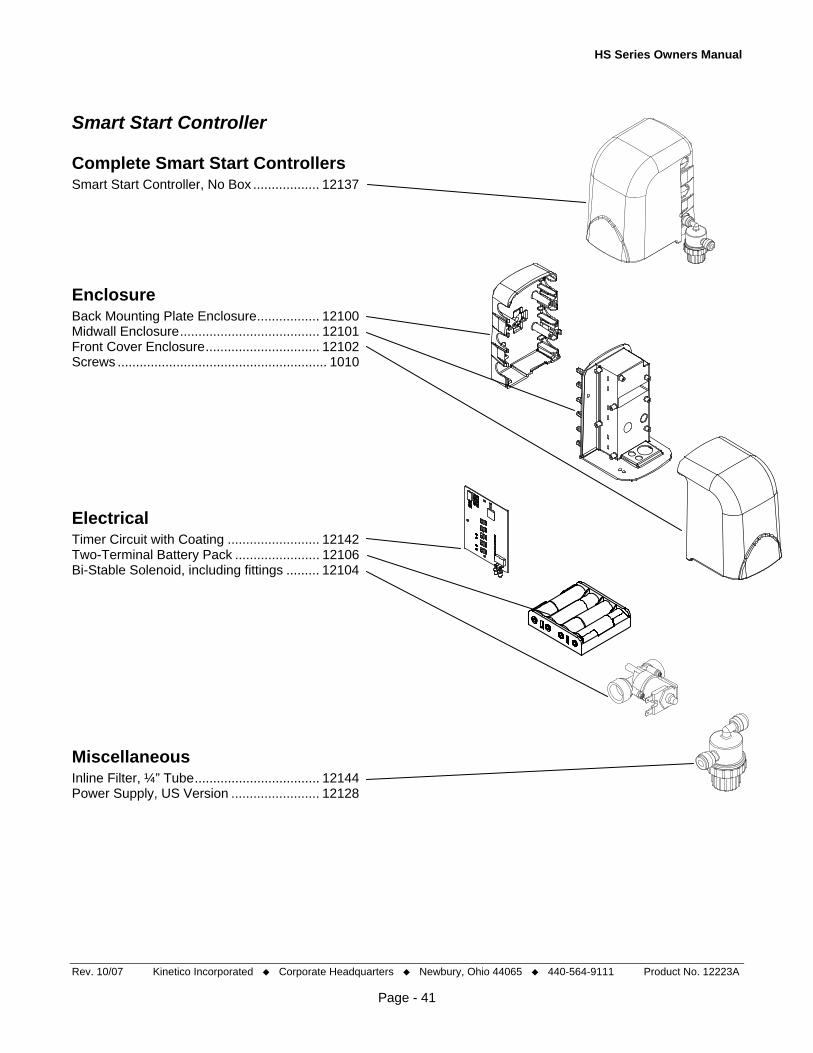
HS Series Owners Manual
Smart Start Controller
Complete Smart Start Controllers Smart Start Controller, No Box .................. 12137
Enclosure Back Mounting Plate Enclosure................. 12100 Midwall Enclosure...................................... 12101 Front Cover Enclosure............................... 12102 Screws ......................................................... 1010
Electrical Timer Circuit with Coating ......................... 12142 Two-Terminal Battery Pack ....................... 12106 Bi-Stable Solenoid, including fittings ......... 12104
Miscellaneous Inline Filter, ¼” Tube.................................. 12144 Power Supply, US Version ........................ 12128
Rev. 10/07 Kinetico Incorporated Corporate Headquarters Newbury, Ohio 44065 440-564-9111 Product No. 12223A
Page - 41
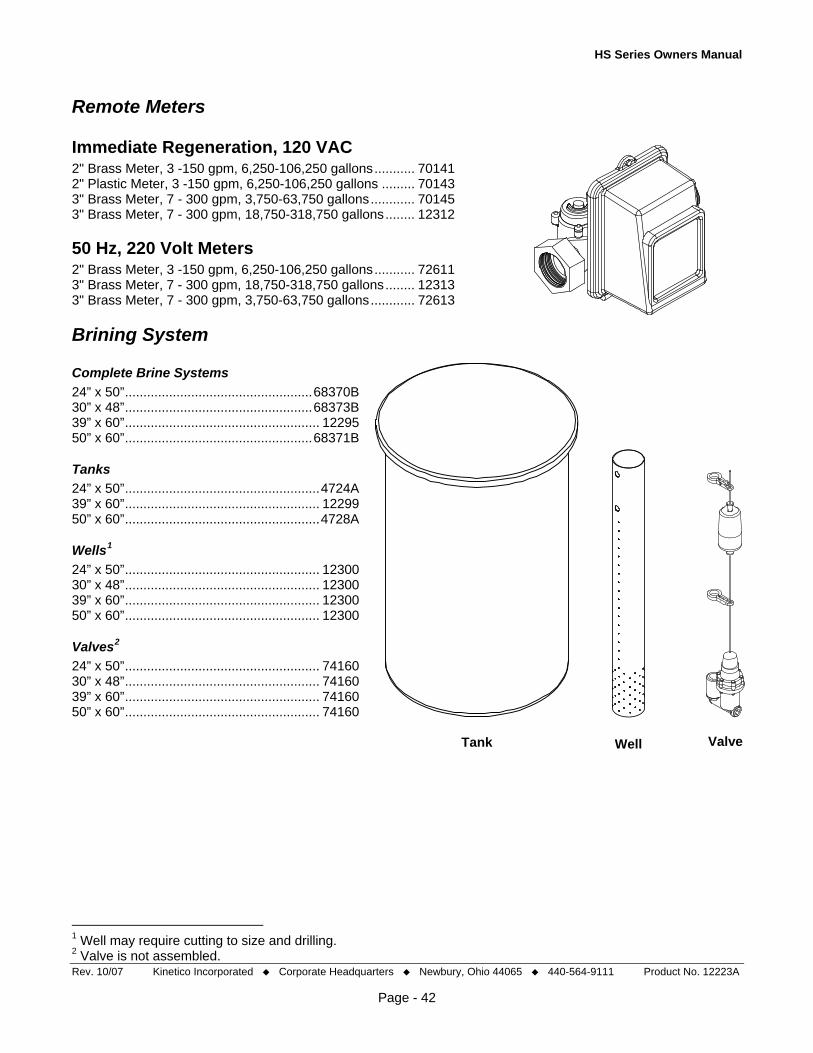
HS Series Owners Manual
Remote Meters
Immediate Regeneration, 120 VAC 2" Brass Meter, 3 -150 gpm, 6,250-106,250 gallons........... 70141 2" Plastic Meter, 3 -150 gpm, 6,250-106,250 gallons ......... 70143 3" Brass Meter, 7 - 300 gpm, 3,750-63,750 gallons............ 70145 3" Brass Meter, 7 - 300 gpm, 18,750-318,750 gallons........ 12312
50 Hz, 220 Volt Meters 2" Brass Meter, 3 -150 gpm, 6,250-106,250 gallons........... 72611 3" Brass Meter, 7 - 300 gpm, 18,750-318,750 gallons........ 12313 3" Brass Meter, 7 - 300 gpm, 3,750-63,750 gallons............ 72613
Brining System
Complete Brine Systems 24” x 50”...................................................68370B 30” x 48”...................................................68373B 39” x 60”..................................................... 12295 50” x 60”...................................................68371B
Tanks 24” x 50”.....................................................4724A 39” x 60”..................................................... 12299 50” x 60”.....................................................4728A
Wells1 24” x 50”..................................................... 12300 30” x 48”..................................................... 12300 39” x 60”..................................................... 12300 50” x 60”..................................................... 12300
Valves2 24” x 50”..................................................... 74160 30” x 48”..................................................... 74160 39” x 60”..................................................... 74160 50” x 60”..................................................... 74160
Tank Well Valve
Rev. 10/07 Kinetico Incorporated Corporate Headquarters Newbury, Ohio 44065 440-564-9111 Product No. 12223A
Page - 42
1 Well may require cutting to size and drilling. 2 Valve is not assembled.
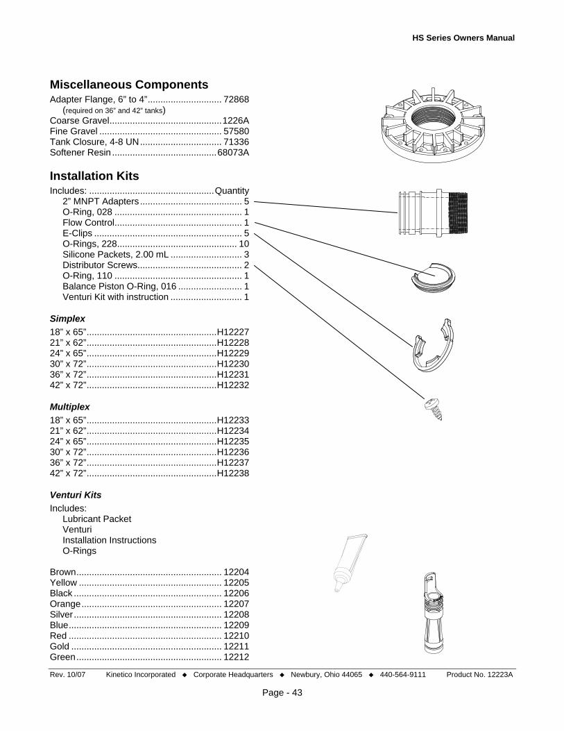
HS Series Owners Manual
Rev. 10/07 Kinetico Incorporated Corporate Headquarters Newbury, Ohio 44065 440-564-9111 Product No. 12223A
Miscellaneous Components Adapter Flange, 6” to 4”............................. 72868 (required on 36” and 42” tanks) Coarse Gravel............................................1226A Fine Gravel ................................................ 57580 Tank Closure, 4-8 UN................................ 71336 Softener Resin .........................................68073A
Installation Kits Includes: .................................................Quantity 2” MNPT Adapters ........................................ 5 O-Ring, 028 .................................................. 1 Flow Control.................................................. 1 E-Clips .......................................................... 5 O-Rings, 228............................................... 10 Silicone Packets, 2.00 mL ............................ 3 Distributor Screws......................................... 2 O-Ring, 110 .................................................. 1 Balance Piston O-Ring, 016 ......................... 1 Venturi Kit with instruction ............................ 1
Simplex 18” x 65”...................................................H12227 21” x 62”...................................................H12228 24” x 65”...................................................H12229 30” x 72”...................................................H12230 36” x 72”...................................................H12231 42” x 72”...................................................H12232
Multiplex 18” x 65”...................................................H12233 21” x 62”...................................................H12234 24” x 65”...................................................H12235 30” x 72”...................................................H12236 36” x 72”...................................................H12237 42” x 72”...................................................H12238
Venturi Kits Includes: Lubricant Packet Venturi Installation Instructions O-Rings Brown......................................................... 12204 Yellow ........................................................ 12205 Black .......................................................... 12206 Orange....................................................... 12207 Silver .......................................................... 12208 Blue............................................................ 12209 Red ............................................................ 12210 Gold ........................................................... 12211 Green......................................................... 12212
Page - 43