owner's manual for vehicle the ultimate driving...
TRANSCRIPT
The UltimateDriving Machine
Owner's Manual for Vehicle

M3

We are pleased you have decided on a BMW M3.
Thorough familiarity with your vehicle will provide you with enhanced control and security when you drive it. Therefore, we have one request:
Read the information contained in this Owner's Manual before driving your new BMW M3 for the first time. It contains important information on vehicle operation that will enable you to make full use of the advanced technical equipment of your BMW M3. In addition, you will receive information on vehicle maintenance to ensure operating and traffic safety as well as the best possible value retention of your vehi-cle. For more detailed information refer to the supplemental manuals.
BMW also makes decisive contributions toward greater safety in traffic through its BMW driver training.
This Owner's Manual should be considered a permanent part of this vehicle. It should stay with the vehicle when sold to provide the next owner with important operating, safety and maintenance information.
We wish you an enjoyable driving experience.
BMW AG

4
Notes
© 2004 Bayerische Motoren WerkeAktiengesellschaftMunich, GermanyReprinting, including excerpts, only with the written consent of BMW AG, Munich. Order No. 01 41 0 158 512US English VIII/04Printed in GermanyPrinted on environmentally friendly paper,bleached without chlorine, suitable for recycling.
About this Owner's Manual
We have made every effort to ensure that you are able to find what you need in this Owner's Manual as quickly as possible. The fastest way to find certain topics is by using the detailed index at the end. If you wish to gain an initial overview of your vehicle, you will find this in the first chapter.
Should you wish to sell your BMW at some time in the future, please remem-ber to hand over this Owner's Manual to the new owner; it is an important part of the vehicle.
Additional sources of information
Should you have any further questions, your BMW center will be glad to assist at any time.
You can find more information about BMW, for example on its technology, on the Internet at www.bmw.com.
Symbols used
Indicates precautions that must be followed precisely in order to
avoid the possibility of personal injury and serious damage to the vehicle.
Indicates information that will assist you in gaining the optimum
benefit from your vehicle and enable you to care more effectively for your vehicle.
Refers to measures that can be taken to help protect the environ-
ment.
Marks the end of a specific item of information.
Indicates special equipment, coun-try-specific equipment and optional extras, as well as equipment and func-tions not yet available at the time of printing.
Vehicle Memory, Key Memory, refer to page 59. Identifies func-
tions that can be specifically adapted for a particular key or vehicle. These adjustments can be performed by your BMW center.
<

5
Notes
Indicates that you should consult the relevant section of this
Owner's Manual for information on a particular part or assembly.
Your individual vehicle
On purchasing your BMW, you have decided in favor of a model with individ-ualized equipment and features. This Owner's Manual will describe all of the equipment that the BMW M3 has to offer you.
We hope you will understand that equipment and features are included that you might not have chosen for your vehicle. You can easily identify any dif-ferences with the aid of the asterisk used to identify all optional equipment and accessories.
If your BMW features equipment such as a car radio or telephone, that is not described in this Owner's Manual, we have enclosed Supplementary Owner's Manuals. We ask you to read these manuals as well.
Status at time of printing
BMW pursues a policy of continuous, ongoing development that is conceived to ensure that our vehicles continue to embody the highest quality and safety standards combined with advanced, state-of-the-art technology. In excep-tional cases, the features described in this Owner's Manual could therefore differ from those on your vehicle.
6
Notes
For your own safety
Maintenance and repair
Advanced technology, e.g. the use of modern materials and high-
performance electronics, requires spe-cially adapted maintenance and repair methods. Therefore, only have corre-sponding work on your BMW carried out by a BMW center or a workshop that works according to BMW repair procedures with correspondingly trained personnel. If work is carried out improperly there is a danger of conse-quential damage and the related safety risks.
<
Proposition 65 warning
California laws require us to state the following warning:
Engine exhaust and a wide variety of automobile components and
parts, including components found in the interior furnishings in a vehicle, con-tain or emit chemicals known to the State of California to cause cancer and birth defects and reproductive harm. In addition, certain fluids contained in vehicles and certain products of com-ponent wear contain or emit chemicals known to the State of California to cause cancer and birth defects or other reproductive harm.Battery posts, terminals and related accessories contain lead and lead com-pounds. Batteries also contain other chemicals known to the State of Cali-fornia to cause cancer. Wash your hands after handling.Used engine oil contains chemicals that have caused cancer in laboratory ani-mals. Always protect your skin by washing thoroughly with soap and water.
<
Parts and accessories
Important safety information!For your own safety, use genuine
parts and accessories approved by BMW.When you purchase accessories tested and approved by BMW and Original BMW Parts, you simultaneously acquire the assurance that they have been thor-oughly tested by BMW to ensure opti-mum performance when installed on your vehicle.BMW warrants these parts to be free from defects in material and workman-ship.BMW will not accept any liability for damages resulting from installation of parts and accessories not approved by BMW.BMW cannot test every product made by other manufacturers to verify if it can be used on a BMW safely and without risk to either the vehicle, its operation, or its occupants.Original BMW Parts, BMW Accessories and other products approved by BMW, together with professional advice on using these items, are available from all BMW centers.Installation and operation of non-BMW approved accessories such as alarms, radios, amplifiers, radar detectors,

7
Notes
wheels, suspension components, brake dust shields, telephones, including operation of any mobile phone from within the vehicle without using an externally mounted antenna, or trans-ceiver equipment, for instance, CBs, walkie-talkie, ham radio or similar accessories, may cause extensive dam-age to the vehicle, compromise its safety, interfere with the vehicle’s elec-trical system or affect the validity of the BMW Limited Warranty. Contact your BMW center for additional information.Do not use key or remote control to lock doors or luggage compartment with anyone inside the vehicle. Refer to the Owner's Manual for more details.
<
Maintenance, replacement, or repair of the emission control
devices and systems may be performed by any automotive repair establishment or individual using any certified auto-motive part.
<
Service and warranty
This manual is supplemented by a Ser-vice and Warranty Information Booklet for US models or a Warranty and Ser-vice Guide Booklet for Canadian mod-els.
We recommend that you read this pub-lication thoroughly.
Your BMW is covered by the following warranties:
>
New Vehicle Limited Warranty
>
Rust Perforation Limited Warranty
>
Federal Emissions System Defect Warranty
>
Federal Emissions Performance War-ranty
>
California Emission Control System Limited Warranty.
Detailed information about these war-ranties is listed in the Service and War-ranty Information Booklet for US mod-els or in the Warranty and Service Guide Booklet for Canadian models.
Reporting safety defects
The following only applies to vehicles owned and operated in the US.
If you believe that your vehicle has a defect which could cause a crash or could cause injury or death, you should immediately inform the National High-way Traffic Safety Administration NHTSA in addition to notifying BMW of North America, LLC, P.O. Box 1227, Westwood, New Jersey 07675-1227, telephone toll-free 1-800-831-1117.
If NHTSA receives similar complaints, it may open an investigation, and if it finds that a safety defect exists in a group of vehicles, it may order a recall and remedy campaign. However, NHTSA cannot become involved in indi-vidual problems between you, your dealer, or BMW of North America, LLC.
To contact NHTSA, you may either call the Auto Safety Hotline toll-free at 1-800-424-9393 or 366-0123 in the Washington, D.C. area, or write to: NHTSA, U.S. Department of Transpor-tation, Washington, D.C. 20590. You can also obtain other information about motor vehicle safety from the Hotline.
Contents
No
tes
About this Owner's Manual 4Additional sources of
information 4Symbols used 4Your individual vehicle 5Status at time of printing 5For your own safety 6Service and warranty 7Reporting safety defects 7
Ove
rvie
w
Cockpit 14Instrument cluster 16Indicator and warning lamps 18Buttons* in steering wheel 22Hazard warning triangle* 23First-aid kit* 23Refueling 24Fuel specifications 25
Co
ntr
ols
an
d f
eat
ure
s
Opening and closing:
Keys 28Central locking system 28Opening and closing – via the
remote control 29Opening and closing – via the
door lock 32Opening and closing – from the
inside 33Luggage compartment lid 34Luggage compartment 36Alarm system* 37Electric power windows 39Glass sunroof, electric* 40
To adjust:
Safe seating position 42Seats 43Manual seat adjustment 43Power seat adjustment* 44Head restraints 45Entering the rear 46Safety belts 46Seat and mirror memory* 48Seat heating* 49Mirrors 50Steering wheel 51
Passenger safety systems:
Airbags 52Transporting children safely 55Vehicle Memory, Key
Memory 59
Contents
9
Driving:
Ignition lock 61Starting the engine and driving
off 62Switching off the engine 64Parking brake 64Manual transmission 65Sequential M gearbox with
Drivelogic* 66Turn signal indicator/Headlamp
flasher 71Washer/wiper system/Rain
sensor* 72Cruise control* 73
Everything under control:
Odometer 75Tachometer 75Engine oil temperature 75Fuel gauge 76Engine coolant temperature
gauge 76Service interval display 77Check Control 77Clock 78Computer 79
Technology for safety and driving convenience:
Park Distance Control (PDC)* 81Dynamic Stability Control
(DSC) 82Flat Tire Monitor 83M Engine dynamics control 85Brake force display 86
Lamps:
Parking lamps/Low beams 87Instrument lighting 88High beams/Standing lamps 88Front fog lamps 89Interior lamps 89
Controlling the climate for pleasant driving:
Automatic climate control 90Roller sun blind* 94
Interior conveniences:
Premium sound system* 95Glove compartment 95Storage compartments 96Microphone* 97Ashtray, front* 98Ashtray, rear* 98Clothes hooks 99
Loading and transporting:
Through-loading system 100Ski bag* 101Cargo loading 102Roof-mounted luggage
rack* 105
Co
ntr
ols
an
d f
eat
ure
s

Contents
Op
era
tio
n, m
ain
ten
anc
e
Special operating instructions:
Break-in procedures 108General driving notes 109Antilock Brake System
(ABS) 111
Wheels and tires:
Tire inflation pressure 112Tire code 114Tire condition 115New wheels and tires 116Snow chains* 118
In the engine compartment:
Hood 119Engine compartment
essentials 120Washer fluids 122Engine oil 122Coolant 124Brake fluid 125
Maintenance:
BMW Maintenance System 126OBD interface socket 128
Ow
ne
r se
rvic
e p
roc
ed
ure
s
Replacement procedures:
Onboard tool kit 132Windshield wiper blades 132Lamps and bulbs 133Tire repair with the M Mobility
system 137Battery 140Fuses 141
Giving and receiving assistance:
Receiving assistance 142Jump-starting 143Towing and tow-starting the
vehicle 145
Te
ch
nic
al d
ata
Engine data 150Dimensions 151Weights 152Capacities 153

Contents
11
Ind
ex
Everything from A to Z 156
12

13
Overview
Controls and features
Operation, maintenance
Owner service procedures
Technical data
Index
Over
view
Cont
rols
Mai
nten
ance
Repa
irs
Data
Inde
x

14
Cockpit

15
1 Parking lamps/Low beams 87
2
>
Turn signal indicators 71
>
Standing lamps 88
>
High beams 88
>
Headlamp flasher 71
>
Computer 79
3 Washer/wiper system/Rain sensor 72
4 Hazard warning flashers
5 Rear window defroster 93
6
>
Initiating an emergency call 142
>
Mobile Service 143
7 Central locking system 28
8 Adjusting the steering wheel 51
9 Horn: the entire surface
10 Fog lamps 89
Cockpit
Over
view
Cont
rols
Mai
nten
ance
Repa
irs
Data
Inde
x

16
Instrument cluster

17
1 Fuel gauge 76
2 Turn signal indicators 20
3 Speedometer
4 Indicator and warning lamps 18 to 21
5 Tachometer and engine oil temper-ature gauge 75
6 Engine coolant temperature gauge 76
7 Indicator and warning lamps 18 to 21
8 Control button for
>
Clock 78
>
Unit of measure of outside tem-perature display 79
9 Display for sequential M gearbox with Drivelogic 67
10 Indicator lamp for Dynamic Stability Control (DSC) 82
11 Display for
>
Trip odometer/Odometer 75
>
Clock 78
>
Service interval 77
>
Computer 79
12 Check Control 77
13 Trip odometer, reset to zero 75
14 M Track mode* indicator lamp 82
15 Indicator and warning lamps 18 to 21
Instrument cluster
Over
view
Cont
rols
Mai
nten
ance
Repa
irs
Data
Inde
x
18
Indicator and warning lamps
Technology that monitors itself
Indicator and warning lamps that are identified by
●
are tested for proper functioning whenever the ignition key is turned. They each light up once for dif-ferent periods of time.
If a fault should occur in one of these systems, the corresponding lamp does not go out after the engine is started, or it lights up while the vehicle is moving. You will see how to react to this below.
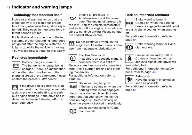
Red: stop immediately
Battery charge current
●
The battery is no longer being charged. There is a malfunction
of the alternator drive belt or in the charging circuit of the alternator. Please contact the nearest BMW center.
If the drive belt is defective, stop and switch off the engine immedi-
ately to prevent overheating and seri-ous engine damage. If the drive belt is defective, increased steering effort is also required.
<
Engine oil pressure
●
An alarm sounds at the same time. The engine oil pressure is
too low. Stop the vehicle immediately and switch off the engine. It is not pos-sible to continue driving. Please contact the nearest BMW center.
Do not continue driving, as the engine could sustain serious dam-
age from inadequate lubrication.
<
Flat Tire Monitor
●
In addition, an acoustic signal is sounded: there is a flat tire.
Reduce speed and carefully come to a stop. Avoid sudden braking and steer-ing maneuvers.For additional information, refer to page 85.
Brake warning lamp
●
If the lamp comes on when the parking brake is not engaged:
check the brake fluid level. It is very important that you follow the instruc-tions on page 125 before driving on. Have the system checked immediately.
Brake warning lamp for Cana-dian models.
Red: an important reminder
Brake warning lamp
●
Comes on when the parking brake is engaged – an additional
acoustic signal sounds when starting off.For additional information, refer to page 64.
Brake warning lamp for Cana-dian models.
Please fasten safety belt
●
Comes on together with an acoustic signal until driver fas-
tens safety belt.For additional information on safety belts, refer to page 46.
Airbags
●
Have the system checked as soon as possible.
For additional information, refer to page 54.

19
Red and yellow: continue driving cautiously
The brake warning lamp lights up together with the yellow indi-cator lamps for ABS
●
and DSC:The entire ABS, CBC and DSC control system has failed. Con-tinue driving cautiously and defensively and avoid full brake
applications. Please have the system checked by your BMW center as soon as possible.For additional information, refer to pages 82, 111.
ABS, CBC and DSC indicator and warning lamps for Canadian models.
Orange: consult the nearest BMW center
Sequential M gearbox with DrivelogicIf the indicator lamp fails to go
out after the engine has been started, or if it comes on during normal driving: this indicates a malfunction in the sys-tem. Have the system checked immedi-ately.Indicator lamp flashes: a system over-load has occurred.For additional information, refer to page 70.
Yellow: check as soon as possible
Engine oil levelComes on while driving and is accompanied by an alarm: the
engine oil level has fallen to the abso-lute minimum; refill as soon as possible. Do not drive more than 30 miles/50 km before refilling.For additional information, refer to page 122.
Engine oil levelComes on after the engine has been shut off and is accompa-
nied by an alarm: add engine oil at your earliest opportunity, such as when you stop to refuel.For additional information, refer to page 122.
Brake pads
●
Have the brake pads checked immediately.
For additional information, refer to page 110.
Flat Tire Monitor
●
The Flat Tire Monitor has been deactivated, either at the button
or in response to a system malfunction. If there is a malfunction, have the sys-ten checked.For additional information, refer to page 85.
Indicator and warning lamps
Over
view
Cont
rols
Mai
nten
ance
Repa
irs
Data
Inde
x

20
Dynamic Stability Control (DSC)
●
The indicator lamp flashes and an acoustic signal sounds: the system is active and governs drive and braking force.If the indicator lamp fails to go out after the engine has been started, or if it comes on during normal driving and stays on:DSC has been deactivated, either at the button or in response to a system mal-function.If there is a malfunction, have the sys-tem checked as soon as possible.For additional information, refer to page 82.
Dynamic Brake Control (DBC)
●
Malfunction in DBC system. Conventional braking efficiency
is available and unrestricted.Have the system checked as soon as possible.For additional information, refer to page 111.
Dynamic Brake Control (DBC) warning lamp for Canadian models.
Add washer fluidThe washer fluid level is too low, top it up at the earliest opportu-
nity.For additional information, refer to page 122.
SERVICE ENGINE SOON
●
If the indicator lamp comes on either continuously or intermit-
tently, this indicates a fault in the emis-sions-related electronic systems. Although the vehicle remains opera-tional, you should have the systems checked by your BMW center at the earliest possible opportunity.For additional information, refer to page 128.
Service Engine Soon indicator lamp for Canadian models.
Engine electronics
●
There is a fault in the electronic engine-management system.
You can continue to drive with reduced engine output or engine speed. Please have the system inspected at your BMW center.
Add coolantCoolant level too low, top up as soon as possible.
For additional information, refer to page 124.
CHECK GAS CAP*
●
This indicator lamp comes on when the gas cap is loose or
missing.Close the gas cap tightly: refer to page 25.
Yellow: for your information
M Track modeLights up when M Track mode is activated.
For additional information, refer to page 83.
Green: for your information
Turn signal indicatorFlashes when turn signals are on. Rapid flashing: indicates a
system malfunction.For additional information, refer to page 71.
Indicator and warning lamps

21
Cruise controlLights up when the cruise con-trol is activated. Ready for oper-
ation via the buttons in the steering wheel.For additional information, refer to page 73.
Front fog lampsLights up whenever the fog lamps are on.
For additional information, refer to page 89.
Blue: for your information
High beamsComes on when the high beams are on or the headlamp flasher
is actuated.For additional information, refer to pages 71, 88.
Indicator and warning lamps
Over
view
Cont
rols
Mai
nten
ance
Repa
irs
Data
Inde
x

22
Buttons* in steering wheel
These buttons let you operate the fol-lowing functions quickly and without being distracted from traffic conditions:
>
Selected radio functions
*
>
The cruise control
*
>
Selected telephone functions
*
>
The voice command system*>M Track mode*, part of Dynamic Sta-
bility Control DSC.
The controls are active only when the corresponding systems and
accessories are switched on.<
Press briefly:
Accept incoming call, start dialing, ter-minate call.
Extended pressure:
Activate and deactivate voice com-mand.
Display/hide telephone book. Display the entries one after another with the forward/backward buttons.
Forward
>RadioPress briefly: next station in station memoryExtended pressure: station search
>CDPress briefly: jump to next trackExtended pressure: search function in track
>CassettePress briefly: jump to next track orstop fast forwardExtended pressure: fast forward
>PhoneScan personal phone book.
Rewind: same functions as forward.
Volume.
Cruise control: select a stored setting.
Cruise control: store and accelerate + or decelerate and store –.
Cruise control: activate/interrupt/deac-tivate
or
M Track mode: switch on/off.
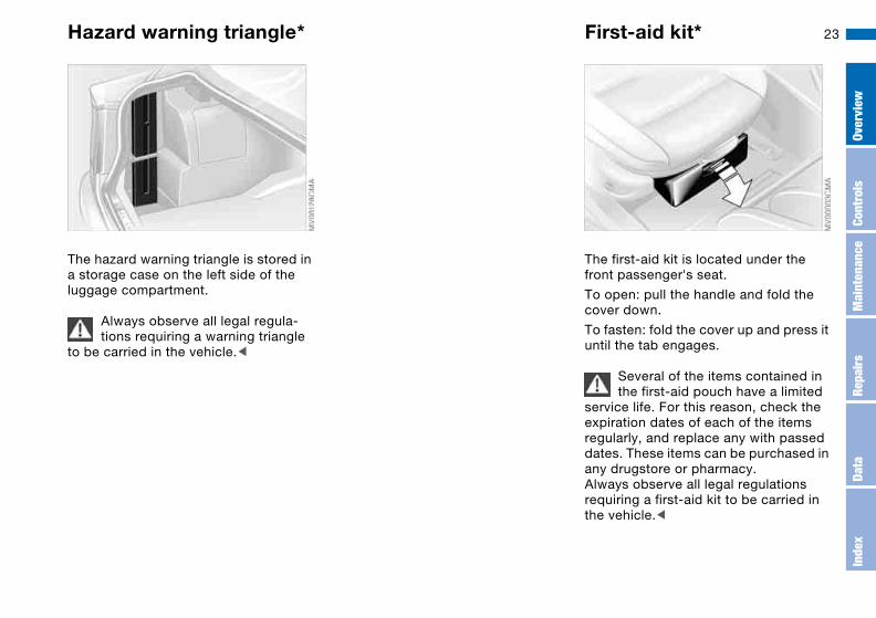
23Hazard warning triangle*
The hazard warning triangle is stored in a storage case on the left side of the luggage compartment.
Always observe all legal regula-tions requiring a warning triangle
to be carried in the vehicle.<
First-aid kit*
The first-aid kit is located under the front passenger's seat.
To open: pull the handle and fold the cover down.
To fasten: fold the cover up and press it until the tab engages.
Several of the items contained in the first-aid pouch have a limited
service life. For this reason, check the expiration dates of each of the items regularly, and replace any with passed dates. These items can be purchased in any drugstore or pharmacy.Always observe all legal regulations requiring a first-aid kit to be carried in the vehicle.<
Over
view
Cont
rols
Mai
nten
ance
Repa
irs
Data
Inde
x

24 Refueling
Fuel filler doorAlways switch off the engine before refueling, as it is not possi-
ble to add fuel with the engine running, and attempts may also trigger the SERVICE ENGINE SOON lamp.<
Press on the rear edge of the fuel filler door to open and close it.
If an electrical malfunction occurs, you can unlock the fuel filler door manually:
Pull the knob with the fuel pump symbol on the right trim panel of the luggage compartment.
When handling fuels, comply with all of the applicable safety precau-
tions posted at the service station.Never carry spare fuel containers in your vehicle. Whether empty or full, these containers can leak, cause an explosion, or lead to fire in the event of a collision.<
Please observe while refuellingOpen the gas cap carefully to pre-vent fuel from spraying out. Fuel
spray may cause injury.<
Place the gas cap in the bracket attached to the fuel filler door.
When refueling, insert the filler nozzle completely into the filler pipe. Lifting the nozzle during refueling
> results in premature pump shutoff>and will reduce the effect of the vapor
recovery system on the pump.
The fuel tank is full when the filler noz-zle shuts off the first time.

25
Closing the gas capPlace the cap in position and turn it until a clearly audible click is heard.
Close the gas cap carefully after refueling until a click is heard.
While closing, be sure not to squeeze the strap which is fastened to the cap. A loose or missing cap will activate the CHECK GAS CAP* lamp.<
Warning lamp* lights up. The gas cap is not properly closed or is missing. Check if the gas
cap is properly closed.
Fuel tank capacity>Approx. 16.6 gal./63 liters, of which>approx. 2.1 gal./8 liters are reserve
capacity.
Do not drive to the last drop of fuel. This can prevent the engine
from operating properly and result in damage.<
Fuel specifications
The engine uses lead-free gasoline only.
Required fuelPremium Unleaded Gasoline, Minimum Octane Rating: AKI 91.
Minimum Octane Rating corresponds to the Anti Knock Index AKI and is deter-mined according to the so-called (R+M)/2 method.
Do not use leaded gasoline, as otherwise the lambda probe and
catalytic converter will be permanently damaged.<
Use high-quality brandsField experience has indicated signifi-cant differences in fuel quality: volatility, composition, additives, etc., among gasolines offered for sale in the United States and Canada. Fuels containing up to and including 10% ethanol or other oxygenates with up to 2.8 % oxygen by weight, that is, 15% MTBE or 3% meth-anol plus an equivalent amount of co-solvent, will not void the applicable warranties with respect to defects in materials or workmanship.
The use of poor-quality fuels may result in drivability, starting and
stalling problems especially under cer-tain environmental conditions such as high ambient temperature and high alti-tude. Should you encounter drivability prob-lems which you suspect could be related to the fuel you are using, we recommend that you respond by switching to a recognized high-quality brand. Failure to comply with these recom-mendations may also result in unsched-uled maintenance.<
Refueling
Over
view
Cont
rols
Mai
nten
ance
Repa
irs
Data
Inde
x

26

27
Overview
Controls and features
Operation, maintenance
Owner service procedures
Technical data
Index
Over
view
Cont
rols
Mai
nten
ance
Repa
irs
Data
Inde
x
28
Opening and closing
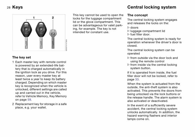
Keys
The key set1 Each master key with remote control
is powered by an extended-life bat-tery that is charged automatically in the ignition lock as you drive. For this reason, user every master key at least twice a year to keep its battery charged. Depending on which master key is recognized when the vehicle is unlocked, different settings are called up and carried out in the vehicle, refer to Vehicle Memory, Key Memory on page 59.
2 Replacement key for storage in a safe place, e.g. your wallet.
This key cannot be used to open the locks for the luggage compartment lid or the glove compartment. This can be advantageous for valet park-ing, for example. The key is not intended for constant use.
Central locking system
The conceptThe central locking system engages and releases the locks on the:
>doors> luggage compartment lid> fuel filler door.
The central locking system is ready for operation whenever the driver's door is closed.
The central locking system can be operated
> from outside via the door lock and using the remote control
> from inside via the central locking system button.
If it is operated from inside, the fuel filler door will not be locked, refer to page 33.
When the system is actuated from the outside, the anti-theft system is also activated. This prevents the doors from being unlocked via the lock buttons or the release handle. The alarm system is also activated or deactivated.
In the event of a sufficiently severe accident, the central locking system unlocks automatically. In addition, the hazard warning flashers and interior lamps come on.
29Opening and closing – via the remote control
The conceptThe remote control also provides two additional functions beyond the central locking feature:
>Switch on the interior lamps, refer to page 30.With this function you can also search for your vehicle – when parked in an underground garage, for instance
>Open the luggage compartment lid, refer to page 30.The luggage compartment lid will open slightly, regardless of whether it was locked or unlocked.
Whenever you unlock or lock the vehi-cle, you simultaneously deactivate/acti-vate the anti-theft system, disarm/arm the alarm system and switch the interior lamps on/off.
Master keys with remote controlSince passengers or animals remaining in the vehicle might be
able to lock the doors from the inside, always take the vehicle's keys with you so that the vehicle can be opened again from the outside at any time.<
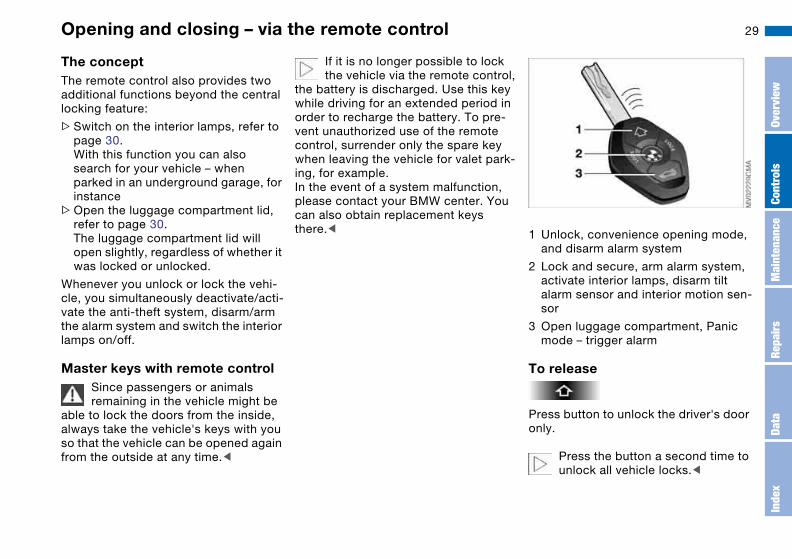
If it is no longer possible to lock the vehicle via the remote control,
the battery is discharged. Use this key while driving for an extended period in order to recharge the battery. To pre-vent unauthorized use of the remote control, surrender only the spare key when leaving the vehicle for valet park-ing, for example.In the event of a system malfunction, please contact your BMW center. You can also obtain replacement keys there.< 1 Unlock, convenience opening mode,
and disarm alarm system
2 Lock and secure, arm alarm system, activate interior lamps, disarm tilt alarm sensor and interior motion sen-sor
3 Open luggage compartment, Panic mode – trigger alarm
To release
Press button to unlock the driver's door only.
Press the button a second time to unlock all vehicle locks.<
Over
view
Cont
rols
Mai
nten
ance
Repa
irs
Data
Inde
x
30
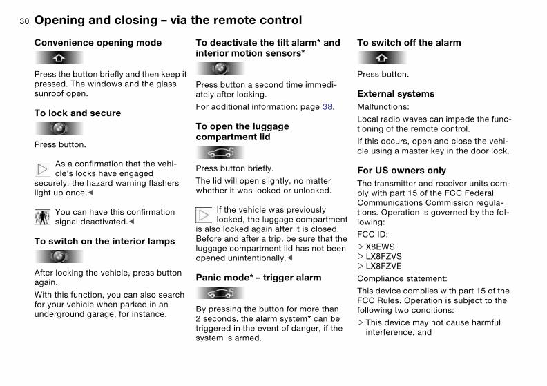
Convenience opening mode
Press the button briefly and then keep it pressed. The windows and the glass sunroof open.
To lock and secure
Press button.
As a confirmation that the vehi-cle's locks have engaged
securely, the hazard warning flashers light up once.<
You can have this confirmation signal deactivated.<
To switch on the interior lamps
After locking the vehicle, press button again.
With this function, you can also search for your vehicle when parked in an underground garage, for instance.
To deactivate the tilt alarm* and interior motion sensors*
Press button a second time immedi-ately after locking.
For additional information: page 38.
To open the luggage compartment lid
Press button briefly.
The lid will open slightly, no matter whether it was locked or unlocked.
If the vehicle was previously locked, the luggage compartment
is also locked again after it is closed.Before and after a trip, be sure that the luggage compartment lid has not been opened unintentionally.<
Panic mode* – trigger alarm
By pressing the button for more than 2 seconds, the alarm system* can be triggered in the event of danger, if the system is armed.
To switch off the alarm
Press button.
External systemsMalfunctions:
Local radio waves can impede the func-tioning of the remote control.
If this occurs, open and close the vehi-cle using a master key in the door lock.
For US owners onlyThe transmitter and receiver units com-ply with part 15 of the FCC Federal Communications Commission regula-tions. Operation is governed by the fol-lowing:
FCC ID:
>X8EWS>LX8FZVS>LX8FZVE
Compliance statement:
This device complies with part 15 of the FCC Rules. Operation is subject to the following two conditions:
>This device may not cause harmful interference, and
Opening and closing – via the remote control

31
> this device must accept any interfer-ence received, including interference that may cause undesired operation.
Any unauthorized modifications to these devices could void the
user's authority to operate the equip-ment.<
Opening and closing – via the remote control
Over
view
Cont
rols
Mai
nten
ance
Repa
irs
Data
Inde
x
32 Opening and closing – via the door lock
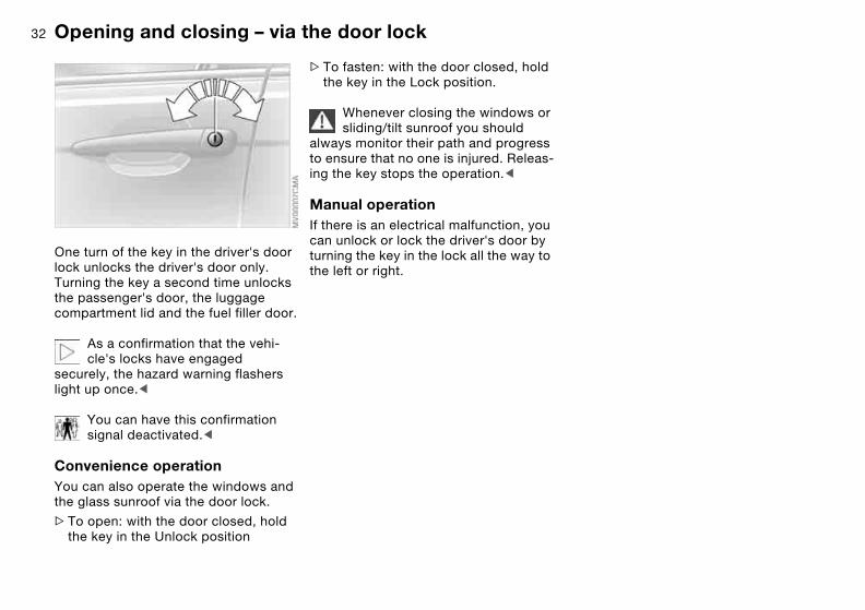
One turn of the key in the driver's door lock unlocks the driver's door only. Turning the key a second time unlocks the passenger's door, the luggage compartment lid and the fuel filler door.
As a confirmation that the vehi-cle's locks have engaged
securely, the hazard warning flashers light up once.<
You can have this confirmation signal deactivated.<
Convenience operationYou can also operate the windows and the glass sunroof via the door lock.
>To open: with the door closed, hold the key in the Unlock position
>To fasten: with the door closed, hold the key in the Lock position.
Whenever closing the windows or sliding/tilt sunroof you should
always monitor their path and progress to ensure that no one is injured. Releas-ing the key stops the operation.<
Manual operationIf there is an electrical malfunction, you can unlock or lock the driver's door by turning the key in the lock all the way to the left or right.

33Opening and closing – from the inside
You can use this button to control the central locking system whenever the doors are closed. The doors and lug-gage compartment lid are unlocked or locked only. The anti-theft system is not activated.
If only the driver's door was unlocked from the outside and
you press the button, then, with the driver's door still open, the passenger's door, the luggage compartment lid and the fuel filler door will unlock, too.If the driver's door is closed, it will be locked.<
If you desire, the central locking system can be activated automati-
cally as soon as you begin to drive. You may also have this adjusted so that it is specific to keys.<
To unlock and open the doors1. Press the button for the central lock-
ing system2. Pull the release handle above the
armrest on the door you wish to open
or
pull the release handle for any door twice: to unlock and open the door.
To lock>Either use the central locking button
to lock both doors at once or>press the individual door lock buttons
down. As an added design feature to prevent the driver from being inad-vertently locked out of the vehicle, the driver's door lock button will not engage as long as the door is open.
Since passengers or animals remaining in the vehicle might be
able to lock the doors from the inside, always take the vehicle's keys with you so that the vehicle can be opened again from the outside at any time.<
Over
view
Cont
rols
Mai
nten
ance
Repa
irs
Data
Inde
x

34 Luggage compartment lid
The lockOnly the master keys fit in the lock for the luggage compartment lid, refer to page 28.
To secure separatelyTurn the master key to the right past the resistance point and then pull it out in the horizontal position.
The luggage compartment lid is locked and disconnected from the central lock-ing system. This feature can be used to prevent unauthorized access to the lug-gage compartment when you surrender the spare key only, refer to page 28. This can be advantageous for valet parking, for example.
To open from the outsidePress the button in the handle recess: the luggage compartment lid opens slightly.
The luggage compartment is lit when the luggage compartment lid is opened.
Manual operationIn the event of electrical malfunction
Turn the master key to the left as far as it will go. The luggage compartment lid will open slightly.
The luggage compartment lid is locked again as soon as you close the lid.

35
To open from inside the vehicleIf the luggage compartment lid has not been locked separately, you can open it with this button in the footwell on the driver's side when the vehicle is sta-tionary.
To closeThe handle recesses in the interior trim panel of the luggage compartment lid make it easier to pull the lid down.
To avoid injuries, be sure that the travel path of the luggage com-
partment lid is clear when it is closed, following the same precautions as with all closing procedures.<
Operate the vehicle only when the luggage compartment lid is com-
pletely closed. Otherwise, exhaust fumes could penetrate the interior of the vehicle.<
If at any time it does become necessary to operate the vehicle with the luggage compartment lid open:
1. Close all windows and the glass sun-roof
2. Greatly increase the quantity of air from the automatic climate control system, refer to page 92.
Luggage compartment lid
Over
view
Cont
rols
Mai
nten
ance
Repa
irs
Data
Inde
x

36
Emergency releaseThis lever releases the luggage com-partment lid from the luggage compart-ment's interior.
Luggage compartment
To fold up and secure the floor panelLift the floor panel with the ring, then use the tab to suspend it from the weather-stripping on the drip rail.
Luggage compartment lid

37
Floor matYou can turn the floor mat over to trans-port soiled objects, etc. The rubber-coated side can be washed and is designed to inhibit sliding.
The fittings at the corners of the lug-gage compartment provide you with a convenient means of attaching luggage compartment nets* and flexible straps for securing luggage.
Refer also to Cargo loading on page 102.
Alarm system*
The conceptThe vehicle alarm system responds:
>When a door, the hood or the lug-gage compartment lid are opened
>To movement inside the vehicle – interior motion sensor
>To changes in vehicle tilt, e.g. as would occur while attempting to steal the wheels or tow the vehicle – tilt alarm sensor system
>To interruption of battery voltage.
The system responds to unauthorized vehicle entry and attempted theft by simultaneously activating the following:
>Sounding an acoustical alarm for 30 seconds
>Activating the hazard warning flash-ers for approx. five minutes
>Flashing the high beams on and off in rhythm with the hazard warning flash-ers.
To arm and disarm the alarm systemWhenever you lock or unlock the vehi-cle via the remote control or a door lock, you simultaneously arm or disarm the alarm system.
You can have various signals set as confirmation that the alarm sys-
tem has been armed or disarmed.<
Even with the system armed, you can open the luggage compartment lid via the button on the remote control. When it is closed, the lid is once again secured.
Extended pressure on the button sets off the alarm – Panic mode, refer to page 30.
Luggage compartment
Over
view
Cont
rols
Mai
nten
ance
Repa
irs
Data
Inde
x
38
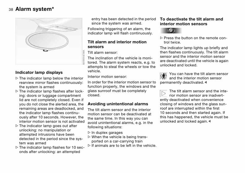
Indicator lamp displays>The indicator lamp below the interior
rearview mirror flashes continuously: the system is armed
>The indicator lamp flashes after lock-ing: doors or luggage compartment lid are not completely closed. Even if you do not close the alerted area, the remaining areas are deadlocked, and the indicator lamp flashes continu-ously after 10 seconds. However, the interior motion sensor is not activated
>The indicator lamp goes out after unlocking: no manipulation or attempted intrusions have been detected in the period since the sys-tem was armed
>The indicator lamp flashes for 10 sec-onds after unlocking: an attempted
entry has been detected in the period since the system was armed.
Following triggering of an alarm, the indicator lamp will flash continuously.
Tilt alarm and interior motion sensorsTilt alarm sensor:
The inclination of the vehicle is moni-tored. The alarm system reacts, e.g. to attempts to steal the wheels or tow the vehicle.
Interior motion sensor:
In order for the interior motion sensor to function properly, the windows and the glass sunroof must be completely closed.
Avoiding unintentional alarmsThe tilt alarm sensor and the interior motion sensor can be deactivated at the same time. In this way you can avoid unintentional alarms, e.g. in the following situations:
> In duplex garages>When the vehicle is being trans-
ported on a car-carrying train> If animals are to be left in the vehicle.
To deactivate the tilt alarm and interior motion sensors
>Press the button on the remote con-trol twice.
The indicator lamp lights up briefly and then flashes continuously. The tilt alarm sensor and the interior motion sensor are deactivated until the vehicle is again unlocked and locked.
You can have the tilt alarm sensor and the interior motion sensor
permanently deactivated.<
The tilt alarm sensor and the inte-rior motion sensor are inadvert-
ently deactivated when convenience closing of windows and the glass sun-roof are interrupted within the first 10 seconds and then started again. If this has happened, the vehicle must be unlocked and locked again.<
Alarm system*

39Electric power windows
To open and close windowsWith the ignition key in position 1 or higher
>Press the switch until you feel resis-tance: the window retracts, or respectively the tilt-out window moves outward; it remains in motion for as long as you maintain pressure on the switch
>Press the switch briefly past the pres-sure point: the window moves auto-matically. Pressing the switch again stops the opening cycle.
You can close the window in the same manner by pulling the switch. The tilt-out window does not close automati-cally.
You can still operate the power win-dows for up to 15 minutes as long as no one has opened and again closed one of the doors.
When leaving the vehicle, always remove the ignition key from the
lock and remember to close the doors to prevent children from operating the power windows and injuring them-selves, etc.<
For convenience operation via the remote control or the door lock, refer to page 32 or 30.
Trap protectionThe front windows are each equipped with a contact strip located on the upper inside of the window frame. If pressure is exerted against this contact strip while the window is being raised, the system will respond by stopping the window and then retracting it a small distance.
Despite trap protection, always be careful to ensure that the closing
path of the window is not obstructed. Some types of objects, for instance very thin objects, might fail to trigger the contact strip in some situations.If the switch is pulled and held beyond the resistance point, this trap protection is overridden.<
Over
view
Cont
rols
Mai
nten
ance
Repa
irs
Data
Inde
x
40 Glass sunroof, electric*
Watch the glass sunroof while it is closing, to avoid any injuries.
When leaving the vehicle, always take the ignition key with you and close the doors, since children could otherwise operate the sunroof and injure them-selves.<
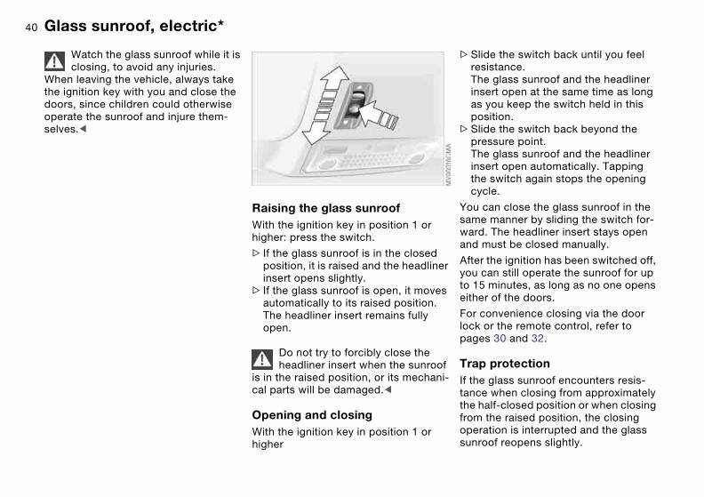
Raising the glass sunroofWith the ignition key in position 1 or higher: press the switch.
> If the glass sunroof is in the closed position, it is raised and the headliner insert opens slightly.
> If the glass sunroof is open, it moves automatically to its raised position. The headliner insert remains fully open.
Do not try to forcibly close the headliner insert when the sunroof
is in the raised position, or its mechani-cal parts will be damaged.<
Opening and closingWith the ignition key in position 1 or higher
>Slide the switch back until you feel resistance.The glass sunroof and the headliner insert open at the same time as long as you keep the switch held in this position.
>Slide the switch back beyond the pressure point.The glass sunroof and the headliner insert open automatically. Tapping the switch again stops the opening cycle.
You can close the glass sunroof in the same manner by sliding the switch for-ward. The headliner insert stays open and must be closed manually.
After the ignition has been switched off, you can still operate the sunroof for up to 15 minutes, as long as no one opens either of the doors.
For convenience closing via the door lock or the remote control, refer to pages 30 and 32.
Trap protectionIf the glass sunroof encounters resis-tance when closing from approximately the half-closed position or when closing from the raised position, the closing operation is interrupted and the glass sunroof reopens slightly.
41
Despite trap protection, always make sure that the sunroof can
close without obstruction, otherwise in some cases, e.g. with thin objects, it is not guaranteed that the closing opera-tion will be interrupted.Trap protection is restricted when the switch is pressed and held beyond the pressure point. The sunroof opens only slightly. If the switch is pressed and held beyond the pressure point again within approx. 2 seconds, trap protec-tion is overridden.< Manual operation
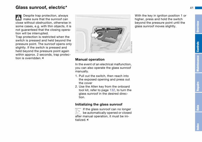
In the event of an electrical malfunction, you can also operate the glass sunroof manually.
1. Pull out the switch, then reach into the exposed opening and press out the cover
2. Use the Allen key from the onboard tool kit, refer to page 132, to turn the glass sunroof in the desired direc-tion.
Initializing the glass sunroofIf the glass sunroof can no longer be automatically opened or closed
after manual operation, it must be ini-tialized.<
With the key in ignition position 1 or higher, press and hold the switch beyond the pressure point until the glass sunroof moves slightly.
Glass sunroof, electric*
Over
view
Cont
rols
Mai
nten
ance
Repa
irs
Data
Inde
x
42
To adjust
Safe seating position
For driving that is relaxed and less likely to cause fatigue, you should select a sitting position that reflects your per-sonal requirements. In combination with the safety belts and airbags, the correct seating position also plays an important role in enhancing occupant safety in the event of an accident. To ensure that the vehicle's safety systems provide you with optimal protection, we request that you direct your careful attention to the following section.
For supplementary information on transporting children refer to page 55.
AirbagsAlways maintain an adequate dis-tance between yourself and the
airbags. Always hold the steering wheel by the rim to keep any chance of injury to hands or arms to an absolute mini-mum should the airbag be deployed. Never allow any objects, individuals or animals to obstruct the areas between passengers and airbags. Never use the front airbag's cover as a storage tray or support for objects of any kind. Never allow front passengers to rest their feet or legs on the airbag cover.<
For airbag locations and additional information on airbags, refer to page 52.
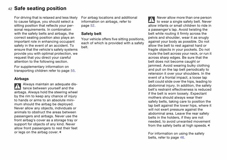
Safety beltYour vehicle offers five sitting positions, each of which is provided with a safety belt.
Never allow more than one person to wear a single safety belt. Never
allow infants or small children to ride in a passenger's lap. Avoid twisting the belt while routing it firmly across the pelvis and shoulder, wear it as snugly against your body as possible. Do not allow the belt to rest against hard or fragile objects in your pockets. Do not route the belt across your neck, or run it across sharp edges. Be sure that the belt does not become caught or jammed. Avoid wearing bulky clothing and pull on the lap belt periodically to retension it over your shoulders. In the event of a frontal impact, a loose lap belt could slide over the hips, leading to abdominal injury. In addition, the safety belt's restraint effectiveness is reduced if the belt is worn loosely. Expectant mothers should always wear their safety belts, taking care to position the lap belt against the lower hips, where it will not exert pressure against the abdominal area. Leave the rear safety belts in the holders, if they are not needed, to avoid unwanted movement from the safety belts at high speeds.<
For information on using the safety belts, refer to page 46.

43Seats
When adjusting your seat, always observe the following precautions
Never try to adjust your seat while operating the vehicle. The seat
could respond with an unexpected movement, and the ensuing loss of vehicle control could lead to an acci-dent. Never ride with the backrest reclined to an extreme angle. This is especially important for the front pas-senger to remember. If you do, there is a risk that you will slide under the safety belt in an accident, thus reducing the protection provided by the safety belt.<
Seat adjustment>Manual seat adjustment, refer to
page 43>Power seat adjustment, refer to
page 44>Head restraint, refer to page 45.
Manual seat adjustment
Seat adjustment1 Forward/backward adjustment
Pull the lever and slide the seat to the desired position.After you release the lever, move the seat forward or backward slightly so that it engages fully
2 HeightPull the lever and apply weight to or remove weight from the seat as required
3 Backrest anglePull the lever and apply weight to or remove weight from the backrest as required
Over
view
Cont
rols
Mai
nten
ance
Repa
irs
Data
Inde
x

44 Power seat adjustment*
Seat adjustment1 Tilt angle
2 Forward/backward adjustment
3 Height
4 Backrest angle
The head restraint and the thigh sup-port are adjusted manually.
Thigh support Pull the lever and adjust the position of the cushion for thigh support as desired.
Adjusting the lumbar support*You can adjust the backrest's contour to support the lordosis of the spine, i.e. the curvature of its lumbar section.
The upper hips and spinal column receive supplementary support to help you maintain a relaxed, upright position.
>To increase or decrease the curva-ture: press front or rear of the switch.
>To shift the curvature up or down: press the upper or lower part of the switch.

45
Adjusting the width of the backrest*Use the controls found along the sides of the seat to adjust the width for the backrest. This way you can set the sides of the seat so that they conform to your body contours.
Increase or decrease backrest width: press front or rear of the switch.
Head restraints
To adjustHeight: pull the head restraint up or push it down.
To bring the head restraint into one of its lowest positions, press
the button, arrow 1, and slide the head restraint down.<
Adjust the angle of the front head restraints by tilting them manually.
You can reduce the risk of spinal injury and whiplash by adjusting
the head restraint to a height at which it is centered roughly at ear level.<
Power seat adjustment*
Over
view
Cont
rols
Mai
nten
ance
Repa
irs
Data
Inde
x
46
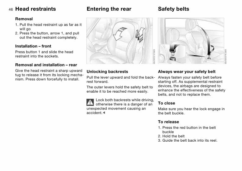
Removal1. Pull the head restraint up as far as it
will go2. Press the button, arrow 1, and pull
out the head restraint completely.
Installation – frontPress button 1 and slide the head restraint into the sockets.
Removal and installation – rearGive the head restraint a sharp upward tug to release it from its locking mecha-nism. Press down forcefully to install.
Entering the rear
Unlocking backrestsPull the lever upward and fold the back-rest forward.
The outer levers hold the safety belt to enable it to be reached more easily.
Lock both backrests while driving, otherwise there is a danger of an
unexpected movement causing an accident.<
Safety belts
Always wear your safety beltAlways fasten your safety belt before starting off. As supplemental restraint devices, the airbags are designed to enhance the effectiveness of the safety belts, and not to replace them.
To closeMake sure you hear the lock engage in the belt buckle.
To release1. Press the red button in the belt
buckle2. Hold the belt3. Guide the belt back into its reel.
Head restraints
47
In the rear, the belt buckle with the word CENTER is provided
exclusively for the passenger sitting in the middle.<
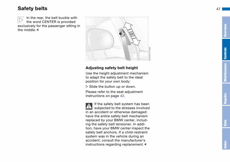
Adjusting safety belt heightUse the height adjustment mechanism to adapt the safety belt to the ideal position for your own body:
>Slide the button up or down.
Please refer to the seat adjustment instructions on page 42.
If the safety belt system has been subjected to the stresses involved
in an accident or otherwise damaged: have the entire safety belt mechanism replaced by your BMW center, includ-ing the safety belt tensioner. In addi-tion, have your BMW center inspect the safety belt anchors. If a child-restraint system was in the vehicle during an accident, consult the manufacturer's instructions regarding replacement.<
Safety belts
Over
view
Cont
rols
Mai
nten
ance
Repa
irs
Data
Inde
x

48 Seat and mirror memory*
You can store and recall three different driver's seat and outside mirror posi-tions.
Memory will not retain the adjust-ments made to the lumbar sup-
ports or the width of the backrests.<
To store1. Ignition key in position 1 or 22. Adjust your seat and outside mirrors
to the desired position3. Press the MEMORY button: the indica-
tor lamp in the button lights up4. Press memory button 1, 2 or 3, as
desired. The indicator lamp goes out.
To select a stored settingDo not select a memory position while the vehicle is moving. If you
do so, there is a risk of accident from unexpected seat movement.<
Driver's door open after unlocking or ignition key in position 1:
>Briefly press memory button 1, 2 or 3, as desired.Movement stops immediately when one of the seat-adjustment or mem-ory buttons is activated during the adjustment process.
With the driver's door closed and the ignition key either removed or in posi-tion 0 or 2:
>Press and hold the desired memory button – 1, 2 or 3 – until the adjust-ment process is completed.
If you press the MEMORY button acci-dentally: press the button again; the indicator lamp goes out.
You can have this feature pro-grammed so that when you use
the remote control from your personal-ized key to unlock your door, your seat and the exterior mirrors will move into your own preferred positions.<
Before activating the programmed adjustment feature, ensure that
the footwell behind the driver's seat is empty and unobstructed. If you fail to do so, persons, animals or objects could be injured or damaged if the seat should move backward.<

49
Passenger-side exterior mirror tilt functionAutomatic curb monitor*
To activate:
1. Select the driver's mirror using the mirror selector switch 1
2. When shifting into Reverse or placing the selector lever in position R, the passenger-side mirror tilts down-ward. This allows the driver to see the area directly adjacent to the vehi-cle, e.g. the curb, during parking.
To deactivate:
Set the mirror selector switch to the passenger-side position.
How far the passenger mirror tilts can be set individually for each
ignition key.<
Seat heating*
The seat cushion and backrest can be heated with the ignition key in position 2.
You can call up different heating modes by repeatedly pressing the buttons.
You can also switch the higher heating modes off directly:
Press the button and hold it slightly longer.
Seat and mirror memory*
Over
view
Cont
rols
Mai
nten
ance
Repa
irs
Data
Inde
x

50 Mirrors
To adjust exterior mirrors1 Switch for 4-way adjustment
2 Switch to select between mirrors
To adjust manuallyThe mirrors can also be adjusted manu-ally:
Press the edges of the lens.
To store the mirror settings, refer to Seat and mirror memory on page 48.
Curved mirrorThe outer part of each mirror conveys a slightly distorted, larger field of vision than the inner part of the mirror. This helps to extend your range of vision toward the rear and to reduce the size of the blind spot.
The mirror on the passenger's side is more convex than the
driver's mirror. The objects reflected in the mirror are closer than they appear. This means that when you are estimat-ing the distance to following vehicles, the mirror is not necessarily a reliable aid. This also applies to the outer parts of each mirror.<
Electric defrostingBoth mirrors are heated automatically in ignition key position 2. Interior rearview mirror with
automatic dimming featureWhile the vehicle is being driven for-ward, this mirror dims light through an infinitely variable range depending on the light's incidence. Two photocells in the interior rearview mirror serve this purpose. One is positioned in the mir-ror's frame, while the other is slightly offset on the opposite side of the mir-ror.
To ensure perfect functioning, keep the photocells clean and the area between the interior rearview mirror and the windshield free of any obstruction like stickers, etc.

51Steering wheel
To adjustNever attempt to adjust the steer-ing wheel while driving the vehicle
– it could respond with unexpected movement, posing a potential accident hazard.<
1. Push the locking lever downward2. Adjust steering column reach and
height for your selected seating posi-tion
3. Pull the lever back up.
Over
view
Cont
rols
Mai
nten
ance
Repa
irs
Data
Inde
x

52
Passenger safety systems
Airbags
1 Front airbags on the driver and pas-senger sides
2 Head airbags for driver and front pas-senger
3 Side airbags on the driver and pas-senger sides – front and rear*
Protective effectThe front airbags protect the driver and passenger in the event of a head-on collision where the protection provided by the safety belt alone would not be adequate. The head and side airbags help provide protection in the event of a collision from the side. The respective side airbag helps support the seat occupant's upper body.
For information on the correct sitting position, refer to page 42.
The side airbags in the rear pas-senger area* of your vehicle may
already have been deactivated by a BMW center. You may have them acti-vated if you desire to do so. Please contact your BMW center for additional information.<
The airbags do not deploy in response to minor collisions, rear
impacts and certain kinds of vehicle rollover.<
Do not apply adhesive materials to the cover panels of the airbags,
cover them or modify them in any other way. Do not attempt to remove the air-bag restraint system from the vehicle. In the event of a malfunction, deactivation or triggered activation – as a response to an accident – of the airbag restraint system, consult your BMW center for inspection, repair or disassembly. Mod-ifications may not be made on either the wiring or the individual components in the airbag system. These include the upholstered covers on the steering wheel, instrument panel, side trim pan-els of the doors and front roof pillars, and on the sides of the headliner. Do not attempt to remove or dismantle the steering wheel. Unprofessional attempts to service the system could lead to failure in an emergency or undesired airbag activation, either of which could result in personal injury. Do not touch the individual components directly after the system has been trig-gered, as otherwise there is a danger of burns.<

53
At all times, occupants should sit upright and be properly restrained
– infants and small children in appropri-ate child-restraint systems; larger chil-dren and adults using the safety belts. Never let an occupant's head rest near or on a side airbag because the inflating airbag could cause a serious or fatal injury. Please note that the word Airbag imprinted on the door trim panel indi-cates the airbag's location.Accident research shows that the saf-est place for children in an automobile is in the rear seat. However, a child sit-ting in the rear seat and not properly restrained may place his or her head on or near the side airbag, if so equipped. For example, a child – even though belted in – may fall asleep with his or her head against the side airbag. It may be difficult for a driver to ensure that children in the rear seat will remain properly positioned at all times and not place their heads on or near the side airbag. Therefore, we recommend that the rear seat side airbags, if provided, be deactivated if you plan to transport children in the rear seat.The rear seat side airbags may already have been deactivated by a BMW cen-ter. If you are uncertain of their status, or wish to have the airbags activated or
deactivated, please contact your BMW center.<
Even when all these guidelines are observed, there is still a small residual risk of injuries to the face, hands and arms occurring from airbag deployment in isolated instances.
In sensitive individuals, the ignition and inflation noise may induce a mild hear-ing loss that is temporary in most cases.
Airbag warning information is also pro-vided on the sun visors.
This is the right way a child should sit in a child restraint when rear side airbags are provided.
Airbags
Over
view
Cont
rols
Mai
nten
ance
Repa
irs
Data
Inde
x
54
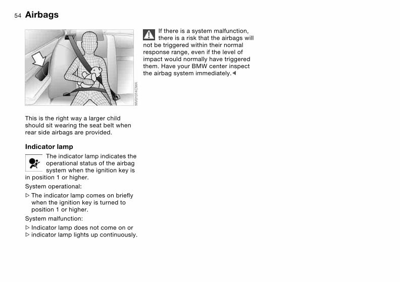
This is the right way a larger child should sit wearing the seat belt when rear side airbags are provided.
Indicator lampThe indicator lamp indicates the operational status of the airbag system when the ignition key is
in position 1 or higher.
System operational:
>The indicator lamp comes on briefly when the ignition key is turned to position 1 or higher.
System malfunction:
> Indicator lamp does not come on or> indicator lamp lights up continuously.
If there is a system malfunction, there is a risk that the airbags will
not be triggered within their normal response range, even if the level of impact would normally have triggered them. Have your BMW center inspect the airbag system immediately.<
Airbags
55Transporting children safely
Commercially available child-restraint systems are designed to be secured with a lap belt or with the lap belt por-tion of a combination lap/shoulder belt. Improperly or inadequately installed restraint systems can increase the risk of injury to children. Always read and follow the instructions that come with the system.
Correct location for installingIn your BMW, all seats equipped with a three-point safety belt – except for the driver's seat – are suitable for installing universal child-restraint systems of all age classes and which have been approved for the age group in question.
Before installing any child-restraint device or child seat,
please read the following:Never install a rearward-facing child-restraint system in the front passenger seat of this vehicle.Your vehicle is equipped with an airbag supplemental restraint system for the front passenger. Because the backrest on any rearward-facing child-restraint system – of the kind designed for infants under 1 year and 20 lbs/9 kg – would be within the airbag's deploy-ment range, you should never mount such a device in the front passenger seat, since the impact of the airbag against the child restraint's backrest could lead to serious or fatal injuries.If it is necessary for a child – not an infant – to ride in the front seat, certain precautions should be taken. First, move the passenger seat as far away from the instrument panel as possible. This important precaution is intended to maximize the distance between the air-bag and the child. Older children should be tightly secured with the safety belt after they have outgrown a booster seat that is appropriate for their age, height, and weight.Younger children should be secured in an appropriate forward-facing child-
restraint system that has first been properly secured with a safety belt.Never install a rearward-facing child-restraint system in the front passenger seat.We strongly urge you to carefully read and comply with the instructions for installation and use provided by the child restraint's manufacturer when-ever you use such a device.The width adjustment of the front pas-senger seat must be set at full width. Do not call up any seat memory posi-tions after the child seat has been installed; there is otherwise a risk of injury.Do not attempt to modify child-restraint systems. If you do this, the protection provided by these systems could be impaired.Be sure that all occupants – of all ages – remain properly and securely restrained at all times.<
Over
view
Cont
rols
Mai
nten
ance
Repa
irs
Data
Inde
x
56
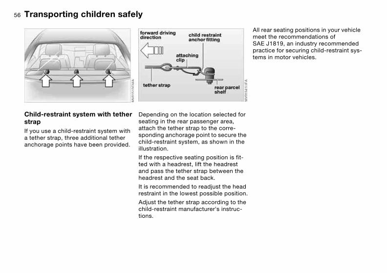
Child-restraint system with tether strapIf you use a child-restraint system with a tether strap, three additional tether anchorage points have been provided.
Depending on the location selected for seating in the rear passenger area, attach the tether strap to the corre-sponding anchorage point to secure the child-restraint system, as shown in the illustration.
If the respective seating position is fit-ted with a headrest, lift the headrest and pass the tether strap between the headrest and the seat back.
It is recommended to readjust the head restraint in the lowest possible position.
Adjust the tether strap according to the child-restraint manufacturer's instruc-tions.
All rear seating positions in your vehicle meet the recommendations of SAE J1819, an industry recommended practice for securing child-restraint sys-tems in motor vehicles.
Transporting children safely
57
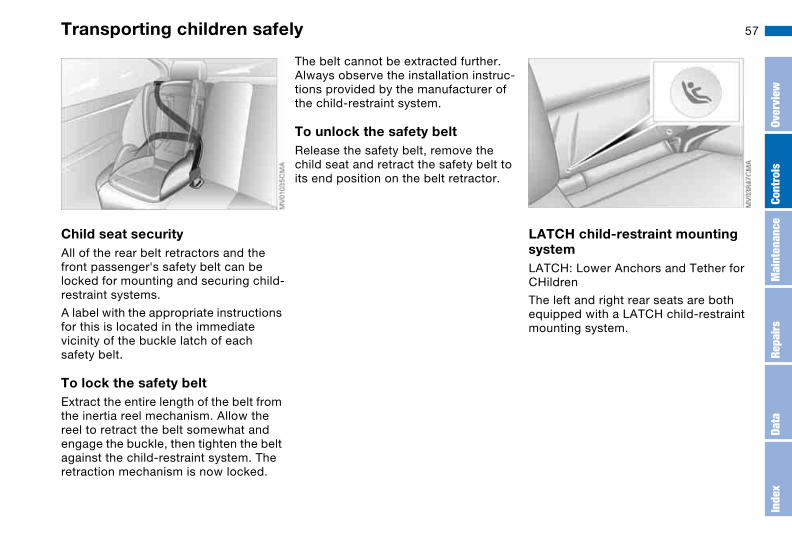
Child seat securityAll of the rear belt retractors and the front passenger's safety belt can be locked for mounting and securing child-restraint systems.
A label with the appropriate instructions for this is located in the immediate vicinity of the buckle latch of each safety belt.
To lock the safety beltExtract the entire length of the belt from the inertia reel mechanism. Allow the reel to retract the belt somewhat and engage the buckle, then tighten the belt against the child-restraint system. The retraction mechanism is now locked.
The belt cannot be extracted further. Always observe the installation instruc-tions provided by the manufacturer of the child-restraint system.
To unlock the safety belt Release the safety belt, remove the child seat and retract the safety belt to its end position on the belt retractor.
LATCH child-restraint mounting systemLATCH: Lower Anchors and Tether for CHildren
The left and right rear seats are both equipped with a LATCH child-restraint mounting system.
Transporting children safely
Over
view
Cont
rols
Mai
nten
ance
Repa
irs
Data
Inde
x

58
The LATCH anchorage points are iden-tified by symbols.
Remove the cover from the outside anchorage by pulling forward. When reinstalling ensure that the recess is on the top.
With through-loading system: tilt the backrest halfway forward to make the cover easier to remove, refer to page 100.
The illustration is an example showing the anchorages for a LATCH child-restraint mounting system at the right rear seat.
Always follow all manufacturer's instructions and observe all safety
precautions when installing the LATCH child-restraint system. Leave the rear safety belts in the holders, if they are not needed, to avoid unwanted move-ment from the safety belts at high speeds.<
Transporting children safely

59Vehicle Memory, Key Memory
How the system functionsYou have probably frequently wished that you could configure individual functions of your vehicles to reflect your own personal requirements. In engi-neering your vehicle, BMW has pro-vided for a number of options for per-sonal adjustment that can be programmed into your vehicle at your BMW center.
The available configuration data fall into two categories, according to whether their primary orientation is the vehicle – Vehicle Memory – or the individual – Key Memory. You can have up to four different basic settings adjusted for four different persons. The only require-ment is that each person uses his or her own remote control key.
When your vehicle is unlocked with the remote control, the vehicle recognizes the individual user by means of a data exchange with the key, and makes adjustments accordingly.
Distinguishing between keysIn order for you to distinguish between different keys, colored decals are sup-plied together with the keys.
What the system can doYour BMW center can provide you with details on the possibilities that the Vehi-cle and Key Memory systems offer:
You will see this symbol through-out the Owner's Manual. It is to
remind you at appropriate places of the settings that are available to you.<
Examples for Vehicle Memory:
>Various signals that can serve as acknowledgment for locking and
unlocking the vehicle, refer to page 29
>Activates/deactivates the 'Follow me home' lamps function, refer to page 87
>Activates/deactivates daytime driv-ing lamps, refer to page 87
>Sets the units of measure for display-ing time, outside temperature, dis-tance traveled and fuel consumption in the instrument cluster
>When you shift into Reverse, an acoustic signal indicates that PDC has been activated, refer to page 81
>Switches on rear window defroster automatically, refer to page 93
>Activates/deactivates various alarm system functions, refer to page 38
>After giving an ice warning, the onboard computer display returns to the previous setting, refer to page 79.
Examples for Key Memory:
>Locks the vehicle automatically after you start off, refer to page 33
>Automatically moves the seat and outside mirror into position for the programmed driver when unlocking the vehicle, refer to page 48
>Automatic tilting of the passenger-side mirror, refer to Automatic curb monitor, page 49
Over
view
Cont
rols
Mai
nten
ance
Repa
irs
Data
Inde
x
60
>After the engine is started, calls up the last selected driving program for each shifting mode, refer to page 69.
Vehicle Memory, Key Memory
61
Driving
Ignition lock
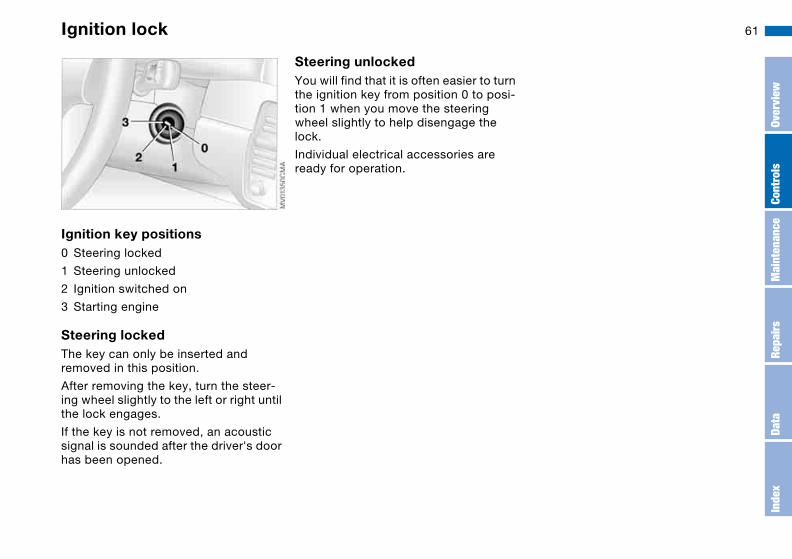
Ignition key positions0 Steering locked
1 Steering unlocked
2 Ignition switched on
3 Starting engine
Steering lockedThe key can only be inserted and removed in this position.
After removing the key, turn the steer-ing wheel slightly to the left or right until the lock engages.
If the key is not removed, an acoustic signal is sounded after the driver's door has been opened.
Steering unlockedYou will find that it is often easier to turn the ignition key from position 0 to posi-tion 1 when you move the steering wheel slightly to help disengage the lock.
Individual electrical accessories are ready for operation.
Over
view
Cont
rols
Mai
nten
ance
Repa
irs
Data
Inde
x

62 Starting the engine and driving off
Do not allow the engine to warm up by leaving it running while the
vehicle remains stationary. Instead, drive off immediately at a moderate engine speed.<
Do not allow the engine to run in enclosed spaces. Otherwise,
breathing the exhaust fumes can lead to unconsciousness and death. The exhaust gases contain carbon monox-ide, an odorless and colorless, but highly toxic gas. Do not leave the vehi-cle unattended with the engine running. An unattended vehicle with a running engine represents a safety hazard.If you leave the vehicle with the engine running, move the gearshift lever into the idling position or the selector lever into position N, as applicable, and apply the parking brake. If you fail to do this, the vehicle could move.<
>Do not press the accelerator pedal while starting the engine
>Do not end the starting procedure too early, but do not continue it for more than 20 seconds
>Release the ignition key immediately when the engine starts
>Do not let the engine warm up in idling position. Instead, begin to drive at moderate engine speeds.
If the engine does not start on the first attempt, such as when it is very hot or cold:
Press the accelerator pedal halfway down while engaging the starter.
Cold starts at very low temperatures below about +57/–156 and at high altitudes above 3,300 ft/1,000 m:
>On the first attempt, engage the starter for approx. 10 seconds
>Press the accelerator pedal halfway down while engaging the starter.
Extended starting attempts, char-acterized by excessively frequent
or long periods with the starter engaged can damage the catalytic con-verter.<
When driving, standing at idle or parking the vehicle, take care to
avoid contact between the hot exhaust system and flammable materials – grass, hay, leaves, etc. Such contact could lead to a fire, resulting in serious personal injury and property damage.<
Manual transmission1. Engage the parking brake2. Gearshift lever in idling position3. Depress the clutch pedal.
If the clutch pedal is not depressed, the engine cannot be started
4. Start the engine. Do not press the accelerator pedal. Do not actuate the starter for too short a time. Do not turn it for more than approx. 20 seconds. Release the ignition key immediately when the engine starts
Sequential M gearbox with Drivelogic1. Depress footbrake2. Move selector lever into position N3. Start the engine. Do not actuate the
starter for too short a time. Do not turn it for more than approx. 20 seconds. Release the ignition key immediately when the engine starts
4. Engage a driving position5. Release footbrake and slowly
depress accelerator pedal.

63
With the engine running, the gear indicator in the SMG Drivelogic
display flashes to indicate that a driving position is engaged with the driver's door open or that the hood is not closed properly, refer to page 67.If neither the pedals, the shift paddles, nor the selector lever are actuated, then the gearbox is automatically taken out of gear after approx. four seconds. It will then be necessary to move the selector lever back to position N before engaging the desired driving position. Driving off is not possible with the hood open.<
Before exiting the vehicle with the engine running, move the selector
lever into position N and apply the parking brake.Never leave the vehicle unattended with the engine running. An unat-tended vehicle with a running engine represents a safety hazard.<
Engine idle speed is controlled by the engine computer system. Increased speeds at start-up are normal and should decrease as the engine warms up. If engine speed does not decrease, service is required.
To prevent the battery from discharg-ing, always deactivate electrical devices that are not in use. Switch the ignition off when the vehicle is not being driven.
Starting the engine and driving off
Over
view
Cont
rols
Mai
nten
ance
Repa
irs
Data
Inde
x

64 Switching off the engine
You should never remove the igni-tion key when the vehicle is in
motion, as the steering lock could engage.When you leave the vehicle, always remove the ignition key and engage the steering lock.<
Always engage the parking brake when parking on downhill roads.
Engaging a gear may not sufficiently secure the vehicle against rolling.<
Manual transmissionTurn the ignition key to position 1 or 0.
Sequential M gearbox with DrivelogicIf you turn the ignition key to position 1 or 0 with the selector lever in the for-ward or reverse position, a gear auto-matically remains engaged.
If you turn the ignition key to position 1 or 0 with the selector lever in position N, a warning tone and the flashing gear indicator in the SMG Drivelogic display remind you that no gear is engaged to secure the vehicle against rolling.
The warning stops after approx. 10 seconds. If you move the selector lever into a forward or reverse position during this time, a gear is automatically engaged.
Parking brake
The parking brake is designed primarily to prevent the vehicle from rolling when it is parked. It operates against the rear wheels.
To engageThe detent engages automatically, and the indicator lamp in the instrument cluster comes on when the ignition key is in position 2, refer to page 18.
To releasePull up slightly on the lever, press the button and lower the lever.

65
If exceptional circumstances make it necessary to engage the
parking brake while the vehicle is in motion, do not pull it with excessive pressure. Keep your thumb pressed against the release button while care-fully pulling the lever up.Excessive pressure can lead to over-braking and loss of traction – fishtailing – at the rear axle.The brake lamps do not come on when the parking brake is engaged.Always engage the parking brake when parking on downhill roads. Engaging a gear may not sufficiently secure the vehicle against rolling.<
To avoid corrosion and one-sided braking, apply the parking brake
from time to time when coasting to a standstill – at a traffic light, for example – provided that it is safe to do so.<
Manual transmission
When shifting gears in the 5th/6th gear plane, be sure to press the
gearshift lever to the right in order to prevent inadvertent selection of a gear in the 3rd/4th gear plane. Do not hold the vehicle in place on slopes by slip-ping or 'riding' the clutch. Use the park-ing brake instead. Riding the clutch leads to severe and premature clutch wear.<
ReverseSelect only when the vehicle is station-ary. Press the shift lever to the left to overcome the resistance.
As you do this, the backup lamps will light up automatically when the ignition key is in position 2.
Parking brake
Over
view
Cont
rols
Mai
nten
ance
Repa
irs
Data
Inde
x

66 Sequential M gearbox with Drivelogic*
The conceptThe sequential M gearbox with Drivelogic is an automated manual gearbox with which clutching and shift-ing is assumed by an electro-hydraulic system.
The SMG Drivelogic is operated via two shift paddles on the steering wheel and the selector lever in the center console.
It offers the following functions:
>Sequential and automated shifting mode
>Ability to choose between different driving programs – Drivelogic
>Gradient assistance, refer to page 69>Upshift display and shift lights, refer
to page 70>RPM matching on downshifts>Driving dependent functions:
The respective driving situation, e.g. cornering, mountain driving or brak-ing, is detected by sensors and taken into account for shifting, e.g. to achieve optimum gear selection dur-ing deceleration and subsequent acceleration
>Slip recognition at the rear axle for increasing driving stability, e.g. dur-ing downshifting on slippery road surfaces
>Operating safety through protection against misshifting.
Under normal operating conditions, fuel consumption is lowest when driving in the first driving program of the auto-mated shifting mode.
Selector lever positionsR: Reverse position
N: Neutral position
Forward position with one-touch mode:
>S: sequential mode>D: automated mode>+: upshifting in sequential mode>–: downshifting in sequential mode.
The SMG Drivelogic is ready for opera-tion from ignition key position two or higher.
For your safety, it is only possible to engage a driving position with the vehi-cle stopped approx. two seconds after engaging position 0 with the footbrake depressed – shift-lock function.

67
SMG display in instrument clusterThe selector lever position, currently engaged gear and selected driving pro-gram are displayed in the instrument cluster.
1 Engaged gear
2 Selected driving program, corre-sponds to the number of illuminated fields, refer to page 69
3 Tapping the selector lever to the right switches over into the displayed shift mode
4 D indicates that an automated shift mode is activated
R – Reverse position Only engage with the vehicle stopped or at low speed, e.g. for rocking free in deep snow.
An intermittent signal tone indi-cates that the reverse position has
been engaged.<
N – NeutralAlways engage before starting the engine.
If the driving situation requires, e.g. when downshifting on slippery roads, the SMG Drivelogic automatically dis-engages and reengages the clutch, i.e. it is not necessary to manually engage position 0.
S – Sequential modeIn the sequential mode all forward gears are to be shifted by the driver.
To switch from automated to sequential mode:
>Tap the selector lever to the right toward S or
>change gears with the selector lever or the shift paddles on the steering wheel.
You do not need to reduce the throttle for shifting.
Sequential M gearbox with Drivelogic*
Over
view
Cont
rols
Mai
nten
ance
Repa
irs
Data
Inde
x

68
Shifting gears with shift paddles on steering wheel:
>To upshift, briefly pull the right pad-dle +
>To downshift, briefly pull the left pad-dle –.
Shift paddles with various widths matched to the shape of your
hand are available from your BMW cen-ter.<
Shifting gears with selector lever:
>To upshift, pull the selector lever backward in the + direction
>To downshift, push the selector lever in the – direction.
No automatic upshifting is carried out in the sequential mode.
You accelerate from higher gears, e.g. during passing, by manually downshift-ing.
In the following situations the SMG Drivelogic in the sequential mode assists you:
>Upshifts and downshifts are only exe-cuted at appropriate combinations of engine rpm and vehicle speed. For instance, downshifts that would result in excessive engine speed are not executed
>During a stop the gearbox is auto-matically downshifted into the first gear so that, e.g. before a traffic light, it is only necessary to accelerate to continue driving
>As speed diminishes, the gearbox downshifts automatically, without you taking any action, just before the vehicle slows to below each gear's minimum speed.
D – Automated modeEach time the engine is started, the automated mode is activated as soon as you move the selector lever into the forward driving position.
In the automated mode all forward gears are shifted automatically.
To switch from sequential to automated mode: tap the selector lever to the right toward D. Watch the display in the instrument cluster, refer to page 67.
For rapid acceleration, e.g. during passing, depress the accelerator pedal completely – kickdown. The gearbox now downshifts depending on the selected driving program.
Even in the automated mode, you can help specify the shifting point: if a gear-dependent minimum speed is exceeded, you can upshift by slowly reducing pressure on the accelerator pedal. In the process, the respective driving situation is detected by sensors and taken into account.
Sequential M gearbox with Drivelogic*

69
DrivelogicDrivelogic makes various driving pro-grams available to you.
Press the Drivelogic repeatedly until the desired driving program is shown in the SMG display of the instrument cluster, refer to page 67.
In the automated mode you can select from five driving programs ranging from convenience mode/winter operation to sporty and highly dynamic.
In the first automated driving program, starting off takes place in second gear, which is advisable under winter road conditions with ice and snow.
In the sequential mode you can choose from six driving programs ranging from balanced, dynamic driving – 1 – to sporty, puristic driving – 6. The sporty, puristic driving program can only be activated when Dynamic Stability Con-trol DSC is switched off, refer to page 82.
To maintain vehicle stability, always drive with the DSC acti-
vated on whenever possible.<
Following each change between the sequential and the automated mode, the last driving program selected in the respective mode is active. Exception: if program 6 had been the last selected sequential driving program, program 5 is activated instead.
Your vehicle is set so that when the engine is started, the last
selected driving program saved in your key is activated for each shifting mode.<
Gradient assistanceThe gradient assistance enables start-ing off on grades with virtually no roll-back. It can be activated in the sequen-tial and automated mode with the vehi-cle stopped and can be used for both forward and reverse driving.
The vehicle may roll slightly before it is held by the gradient assis-
tance after releasing the footbrake.Two seconds after the footbrake is released, the vehicle begins to roll, as it is no longer held with the gradient assistance.<
1. Depress footbrake with vehicle stopped
2. Activate the gradient assistance by pulling the left paddle for at least 0.5 seconds. An increase in the engine speed indicates that the gra-dient assistance is activated
Briefly pulling the left paddle again deactivates the gradient assis-
tance again.<
3. Release the footbrake and start off within 2 seconds.
The gradient assistance must be reacti-vated before each use.
Sequential M gearbox with Drivelogic*
Over
view
Cont
rols
Mai
nten
ance
Repa
irs
Data
Inde
x
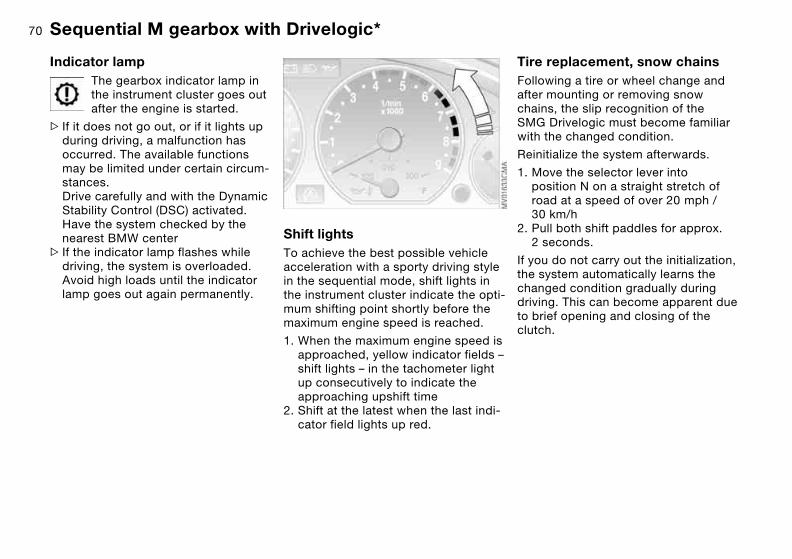
70
Indicator lampThe gearbox indicator lamp in the instrument cluster goes out after the engine is started.
> If it does not go out, or if it lights up during driving, a malfunction has occurred. The available functions may be limited under certain circum-stances.Drive carefully and with the Dynamic Stability Control (DSC) activated. Have the system checked by the nearest BMW center
> If the indicator lamp flashes while driving, the system is overloaded. Avoid high loads until the indicator lamp goes out again permanently.
Shift lightsTo achieve the best possible vehicle acceleration with a sporty driving style in the sequential mode, shift lights in the instrument cluster indicate the opti-mum shifting point shortly before the maximum engine speed is reached.
1. When the maximum engine speed is approached, yellow indicator fields – shift lights – in the tachometer light up consecutively to indicate the approaching upshift time
2. Shift at the latest when the last indi-cator field lights up red.
Tire replacement, snow chainsFollowing a tire or wheel change and after mounting or removing snow chains, the slip recognition of the SMG Drivelogic must become familiar with the changed condition.
Reinitialize the system afterwards.
1. Move the selector lever into position N on a straight stretch of road at a speed of over 20 mph / 30 km/h
2. Pull both shift paddles for approx. 2 seconds.
If you do not carry out the initialization, the system automatically learns the changed condition gradually during driving. This can become apparent due to brief opening and closing of the clutch.
Sequential M gearbox with Drivelogic*

71Turn signal indicator/Headlamp flasher
1 High beams
2 Headlamp flasher
3 Turn signal indicators
To signal brieflyPress the lever up to the resistance point but not beyond. It then returns to the center position when released.
If the flashing of the indicator lamp and the clicking from the relay are
both faster than usual, one of the turn signal indicators has failed.<
Over
view
Cont
rols
Mai
nten
ance
Repa
irs
Data
Inde
x
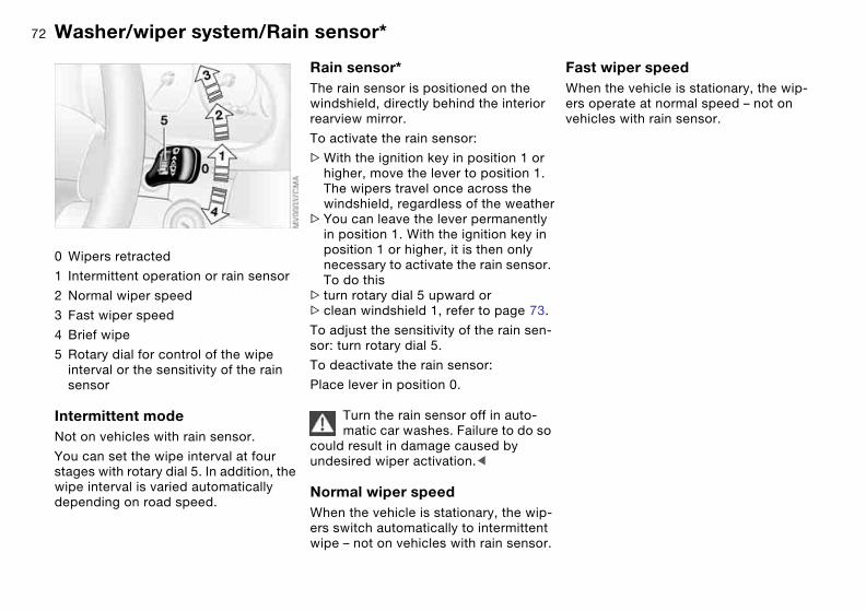
72 Washer/wiper system/Rain sensor*
0 Wipers retracted
1 Intermittent operation or rain sensor
2 Normal wiper speed
3 Fast wiper speed
4 Brief wipe
5 Rotary dial for control of the wipe interval or the sensitivity of the rain sensor
Intermittent modeNot on vehicles with rain sensor.
You can set the wipe interval at four stages with rotary dial 5. In addition, the wipe interval is varied automatically depending on road speed.
Rain sensor*The rain sensor is positioned on the windshield, directly behind the interior rearview mirror.
To activate the rain sensor:
>With the ignition key in position 1 or higher, move the lever to position 1. The wipers travel once across the windshield, regardless of the weather
>You can leave the lever permanently in position 1. With the ignition key in position 1 or higher, it is then only necessary to activate the rain sensor. To do this
> turn rotary dial 5 upward or>clean windshield 1, refer to page 73.
To adjust the sensitivity of the rain sen-sor: turn rotary dial 5.
To deactivate the rain sensor:
Place lever in position 0.
Turn the rain sensor off in auto-matic car washes. Failure to do so
could result in damage caused by undesired wiper activation.<
Normal wiper speedWhen the vehicle is stationary, the wip-ers switch automatically to intermittent wipe – not on vehicles with rain sensor.
Fast wiper speedWhen the vehicle is stationary, the wip-ers operate at normal speed – not on vehicles with rain sensor.
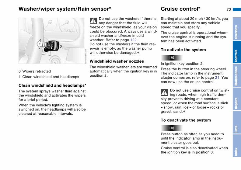
73
0 Wipers retracted
1 Clean windshield and headlamps
Clean windshield and headlamps*The system sprays washer fluid against the windshield and activates the wipers for a brief period.
When the vehicle's lighting system is switched on, the headlamps will also be cleaned at reasonable intervals.
Do not use the washers if there is any danger that the fluid will
freeze on the windshield, as your vision could be obscured. Always use a wind-shield washer antifreeze in cold weather. Refer to page 122.Do not use the washers if the fluid res-ervoir is empty, as the washer pump will otherwise be damaged.<
Windshield washer nozzlesThe windshield washer jets are warmed automatically when the ignition key is in position 2.
Cruise control*
Starting at about 20 mph / 30 km/h, you can maintain and store any vehicle speed that you specify.
The cruise control is operational when-ever the engine is running and the sys-tem has been activated.
To activate the system
In ignition key position 2:
Press the button in the steering wheel. The indicator lamp in the instrument cluster comes on, refer to page 21. You can now use the cruise control.
Do not use cruise control on twist-ing roads, when high traffic den-
sity prevents driving at a constant speed, or when the road surface is slick – snow, rain, ice – or loose – rocks or gravel, sand.<
To deactivate the system
Press button as often as you need to until the indicator lamp in the instru-ment cluster goes out.
Cruise control is also deactivated when the ignition key is in position 0.
Washer/wiper system/Rain sensor*
Over
view
Cont
rols
Mai
nten
ance
Repa
irs
Data
Inde
x

74
The speed stored in memory is deleted.
To store and maintain speed or to accelerate
Press button + briefly:
The system stores and maintains the current vehicle speed. Every time you tap the button, the speed increases by approx. 0.6 mph / 1 km/h.
Press and hold button +:
The vehicle accelerates without pres-sure on the accelerator pedal. When you release the button, the system stores and maintains the current speed.
If on a downhill gradient the engine braking effect is not suffi-
cient, the controlled speed can be exceeded. Speed can drop on uphill grades if the engine output is insuffi-cient.<
To decelerate
Press button – briefly:
When cruise control is active, every tap of the button reduces the speed by approx. 0.6 mph / 1 km/h.
Press and hold button –:
With the cruise control active, the sys-tem automatically reduces the throttle opening to slow the vehicle. When you release the button, the system stores and maintains the current speed.
To interrupt the cruise control
When the system is activated, press the button. The indicator lamp stays on. You can use the cruise control again whenever you want by calling up the speed that was stored last.
In addition, cruise control is interrupted automatically:
>When the brakes are applied>When pressing down the clutch pedal> If you exceed or fall below the pro-
grammed speed for an extended period – by depressing the accelera-tor, for example
>Sequential M gearbox with Drivel-ogic, refer to page 66: when shifting in the sequential mode.
To recall the stored setting
Press button:
The vehicle accelerates to and main-tains the last speed stored.
Cruise control*
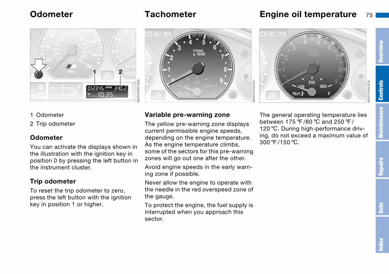
75
Everything under control
Odometer
1 Odometer
2 Trip odometer
OdometerYou can activate the displays shown in the illustration with the ignition key in position 0 by pressing the left button in the instrument cluster.
Trip odometerTo reset the trip odometer to zero, press the left button with the ignition key in position 1 or higher.
Tachometer
Variable pre-warning zoneThe yellow pre-warning zone displays current permissible engine speeds, depending on the engine temperature. As the engine temperature climbs, some of the sectors for this pre-warning zones will go out one after the other.
Avoid engine speeds in the early warn-ing zone if possible.
Never allow the engine to operate with the needle in the red overspeed zone of the gauge.
To protect the engine, the fuel supply is interrupted when you approach this sector.
Engine oil temperature
The general operating temperature lies between 1757/806 and 2507/ 1206. During high-performance driv-ing, do not exceed a maximum value of 3007/1506.
Over
view
Cont
rols
Mai
nten
ance
Repa
irs
Data
Inde
x
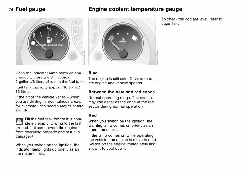
76 Fuel gauge
Once the indicator lamp stays on con-tinuously, there are still approx. 2 gallons/8 liters of fuel in the fuel tank.
Fuel tank capacity approx. 16.6 gal./ 63 liters.
If the tilt of the vehicle varies – when you are driving in mountainous areas, for example – the needle may fluctuate slightly.
Fill the fuel tank before it is com-pletely empty. Driving to the last
drop of fuel can prevent the engine from operating properly and result in damage.<
When you switch on the ignition, the indicator lamp lights up briefly as an operation check.
Engine coolant temperature gauge
BlueThe engine is still cold. Drive at moder-ate engine and vehicle speeds.
Between the blue and red zonesNormal operating range. The needle may rise as far as the edge of the red sector during normal operation.
RedWhen you switch on the ignition, the warning lamp comes on briefly as an operation check.
If the lamp comes on while operating the vehicle: the engine has overheated. Switch off the engine immediately and allow it to cool down.
To check the coolant level, refer to page 124.

77Service interval display
Remaining distance to next serviceThe displays shown in the illustration appear for a few seconds when the ignition key is in position 1 or higher or after the engine is started.
The next service due appears with the message OIL SERVICE or INSPECTION, together with the dis-tance remaining in miles – in kilometers in Canada – before the next scheduled service.
The computer bases its calculations of the remaining distance on the preced-ing driving style.
A flashing message and a '–' in front of the number mean that the service inter-val has already been exceeded by the distance shown on the display. Please contact your BMW center for an appointment.
Check Control
DisplayWhen the ignition key is in position 2, the following information and/or condi-tions are indicated using symbols until the conditions have been corrected.
1 Inspect the low-beam and high-beam headlamps, as well as the parking lamps
2 Door open
3 Luggage compartment lid open
4 Check tail or brake lamps
When you open the driver's door, after having turned the ignition key to posi-tion 0, you will hear an acoustic signal for a few seconds to remind you that the lamps have not been switched off.
Over
view
Cont
rols
Mai
nten
ance
Repa
irs
Data
Inde
x
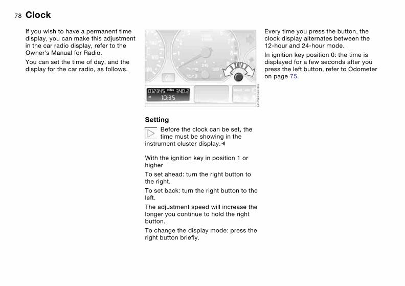
78 Clock
If you wish to have a permanent time display, you can make this adjustment in the car radio display, refer to the Owner's Manual for Radio.
You can set the time of day, and the display for the car radio, as follows.
SettingBefore the clock can be set, the time must be showing in the
instrument cluster display.<
With the ignition key in position 1 or higher
To set ahead: turn the right button to the right.
To set back: turn the right button to the left.
The adjustment speed will increase the longer you continue to hold the right button.
To change the display mode: press the right button briefly.
Every time you press the button, the clock display alternates between the 12-hour and 24-hour mode.
In ignition key position 0: the time is displayed for a few seconds after you press the left button, refer to Odometer on page 75.

79Computer
Mode selectionWith the ignition key in position 1 or higher, you can use the onboard com-puter button BC in the turn signal lever to retrieve information from the com-puter for display in the instrument clus-ter.
Every time you tap the onboard com-puter button BC, the display changes to the next function in sequence.
Order of the displays:
>Time>Outside temperature>Average fuel consumption>Range>Average speed.
When the ignition key is in position 1 or higher, the last active setting is dis-played.
Outside temperatureYou can change the units of measure 7/6 for the outside temperature dis-play by pressing the right-hand reset button in the instrument cluster while the temperature display is active. The units of measure 7/6 in the tempera-ture display of the automatic climate control change automatically, refer to page 90.
Ice warningIf the outside temperature drops to about 37.57/+36, then the computer will automatically switch to a display of the outside temperature. In addition, a signal sounds as a warning and the dis-play flashes for a brief period.
Over
view
Cont
rols
Mai
nten
ance
Repa
irs
Data
Inde
x

80
After giving an ice warning, the display returns to the previous
setting.<
The ice warning does not alter the fact that surface ice can form at
temperatures above 37.57/+36, on bridges or shaded road surfaces, for instance.<
Average fuel consumptionIf you press the onboard computer but-ton BC in the turn signal lever for longer while the average fuel consumption is being displayed, a new consumption value is calculated from that point in time.
If you wish, you can have the aver-age fuel consumption displayed in
a different unit of measure.<
RangeThe display shows a range estimate based on the available fuel. The amount of fuel remaining in the tank is mea-sured, the estimated range is calcu-lated taking into account the operating conditions over the last 20 miles/30 km.
It is important that you refuel when the cruising range falls below
approx. 35 miles/50 kilometers. Other-wise, the engine cannot be guaranteed to operate properly and damage may result.<
Average speedAny time spent when the vehicle is sta-tionary and the engine is shut off is ignored for the calculation.
To reset the average speed: press the onboard computer button BC in the turn signal lever for approx. 2 seconds.
Computer
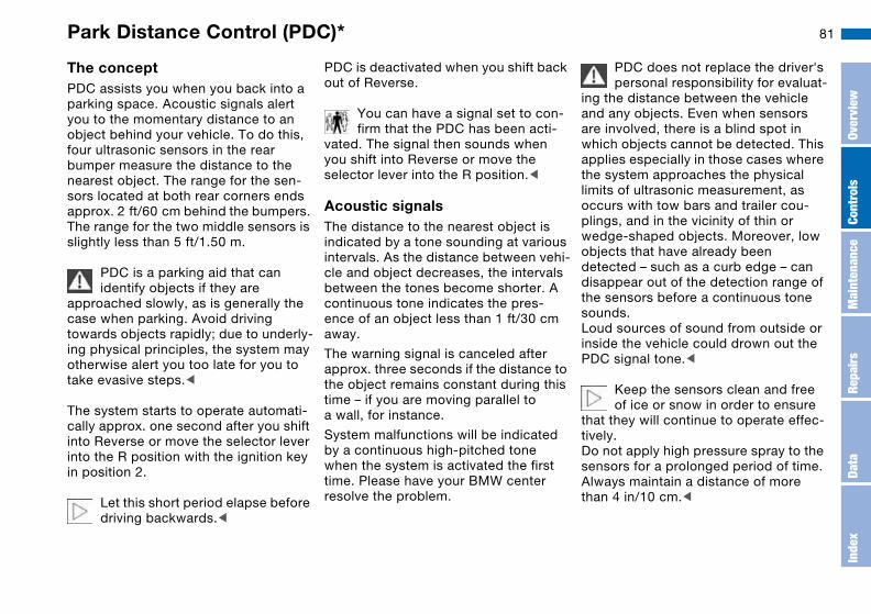
81
Technology for safety and driving convenience
Park Distance Control (PDC)*
The conceptPDC assists you when you back into a parking space. Acoustic signals alert you to the momentary distance to an object behind your vehicle. To do this, four ultrasonic sensors in the rear bumper measure the distance to the nearest object. The range for the sen-sors located at both rear corners ends approx. 2 ft/60 cm behind the bumpers. The range for the two middle sensors is slightly less than 5 ft/1.50 m.
PDC is a parking aid that can identify objects if they are
approached slowly, as is generally the case when parking. Avoid driving towards objects rapidly; due to underly-ing physical principles, the system may otherwise alert you too late for you to take evasive steps.<
The system starts to operate automati-cally approx. one second after you shift into Reverse or move the selector lever into the R position with the ignition key in position 2.
Let this short period elapse before driving backwards.<
PDC is deactivated when you shift back out of Reverse.
You can have a signal set to con-firm that the PDC has been acti-
vated. The signal then sounds when you shift into Reverse or move the selector lever into the R position.<
Acoustic signalsThe distance to the nearest object is indicated by a tone sounding at various intervals. As the distance between vehi-cle and object decreases, the intervals between the tones become shorter. A continuous tone indicates the pres-ence of an object less than 1 ft/30 cm away.
The warning signal is canceled after approx. three seconds if the distance to the object remains constant during this time – if you are moving parallel to a wall, for instance.
System malfunctions will be indicated by a continuous high-pitched tone when the system is activated the first time. Please have your BMW center resolve the problem.
PDC does not replace the driver's personal responsibility for evaluat-
ing the distance between the vehicle and any objects. Even when sensors are involved, there is a blind spot in which objects cannot be detected. This applies especially in those cases where the system approaches the physical limits of ultrasonic measurement, as occurs with tow bars and trailer cou-plings, and in the vicinity of thin or wedge-shaped objects. Moreover, low objects that have already been detected – such as a curb edge – can disappear out of the detection range of the sensors before a continuous tone sounds.Loud sources of sound from outside or inside the vehicle could drown out the PDC signal tone.<
Keep the sensors clean and free of ice or snow in order to ensure
that they will continue to operate effec-tively.Do not apply high pressure spray to the sensors for a prolonged period of time. Always maintain a distance of more than 4 in/10 cm.<
Over
view
Cont
rols
Mai
nten
ance
Repa
irs
Data
Inde
x

82 Dynamic Stability Control (DSC)
The conceptDSC supports vehicle stability, even in critical driving situations.
DSC optimizes driving stability and traction during acceleration and when you are starting from a standstill. In addition, it also recognizes unstable vehicle conditions, such as understeer-ing and oversteering. By reducing engine power and applying brakes at the wheels, DSC helps to keep the vehicle on a steady course within phys-ically feasible limits.
DSC starts up automatically each time you start the engine.
The laws of physics cannot be repealed, even with DSC. The
driver remains responsible for the con-sequences of any inadequate driving style. Therefore, do not take any risks because of the additional safety pro-vided. Do not make any modifications to the DSC system. Allow only autho-rized technicians to perform service procedures on the DSC.<
Indicator lamp for DSCThe indicator lamp in the instru-ment cluster will go out shortly after the ignition has been
switched on, refer to page 20.
>The indicator lamp flashes: DSC is active and is controlling the drive torque based on driving conditions
>The indicator lamp does not go out after the engine is started or lights up continuously while you are driving: DSC has been deactivated via the button or is defective.
You can continue to drive the vehicle normally without DSC. In the event of a malfunction, contact a BMW center or a workshop that works according to BMW requirements with appropriately trained personnel.
M Track mode*M track mode is a feature of the Dynamic Stability Control DSC, designed for driving on dry roads. It allows you to drive with higher longitu-dinal and lateral acceleration, whereas driving stability is somewhat reduced. Only in its absolute limit range will the system try to stabilize the vehicle by reducing engine power and applying
brakes to the wheels. Under these driv-ing conditions the driver must be pre-pared to perform corrective steering movements if necessary.
By default, M Track mode is off after each engine start.
While M Track mode is active, sta-bilising interventions are per-
formed to a reduced extent only.<
To maintain vehicle stability, always drive with DSC switched
on and M Track mode switched off whenever possible.<
Indicator lamp for M Track modeThe indicator lamp goes out shortly after the ignition is switched on.
> Indicator lamp stays on: M Track mode ist on
> Indicator lamp stays on and DSC indicator lamp flashes:M Track mode is actively regulating drive torque and braking forces.
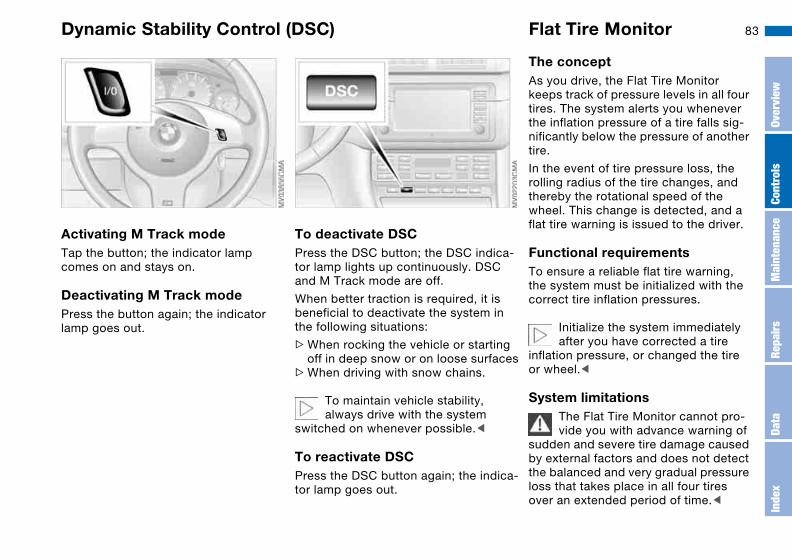
83
Activating M Track modeTap the button; the indicator lamp comes on and stays on.
Deactivating M Track modePress the button again; the indicator lamp goes out.
To deactivate DSCPress the DSC button; the DSC indica-tor lamp lights up continuously. DSC and M Track mode are off.
When better traction is required, it is beneficial to deactivate the system in the following situations:
>When rocking the vehicle or starting off in deep snow or on loose surfaces
>When driving with snow chains.
To maintain vehicle stability, always drive with the system
switched on whenever possible.<
To reactivate DSCPress the DSC button again; the indica-tor lamp goes out.
Flat Tire Monitor
The conceptAs you drive, the Flat Tire Monitor keeps track of pressure levels in all four tires. The system alerts you whenever the inflation pressure of a tire falls sig-nificantly below the pressure of another tire.
In the event of tire pressure loss, the rolling radius of the tire changes, and thereby the rotational speed of the wheel. This change is detected, and a flat tire warning is issued to the driver.
Functional requirementsTo ensure a reliable flat tire warning, the system must be initialized with the correct tire inflation pressures.
Initialize the system immediately after you have corrected a tire
inflation pressure, or changed the tire or wheel.<
System limitationsThe Flat Tire Monitor cannot pro-vide you with advance warning of
sudden and severe tire damage caused by external factors and does not detect the balanced and very gradual pressure loss that takes place in all four tires over an extended period of time.<
Dynamic Stability Control (DSC)
Over
view
Cont
rols
Mai
nten
ance
Repa
irs
Data
Inde
x

84
The system could issue a false warning or function in a delayed manner in the following situations:
>System was not initialized >You are driving on a snow-covered or
slippery road surface>Performance-oriented driving: slip at
the drive wheels, high levels of lateral acceleration
>You are driving with snow chains
Initializing the systemThe initialization is completed while you are driving, and can be
interrupted at any time. Initialization is automatically continued when you con-tinue driving. When driving with snow chains, do not initialize the system.<
1. Before driving off, start the engine but do not start driving
2. Press the button as long as you need to, but no more than 8 seconds, until the indicator lamp in the instrument cluster lights up in yellow for several seconds
3. Drive off. Initialization is completed during the drive without any feed-back issued.
When driving with snow chains, do not initialize the system.< To activate/deactivate the system
The system is automatically activated in ignition key position 2 and conse-quently is on whenever the vehicle is operated.
To deactivate the system: tap the but-ton, the indicator lamp will light up yel-low.
To activate the system: tap the button again; the indicator lamp goes out.
Deactivate the system when snow chains are mounted, since false warn-ings and undetected losses in pressure are possible under these kinds of con-ditions.
Flat Tire Monitor
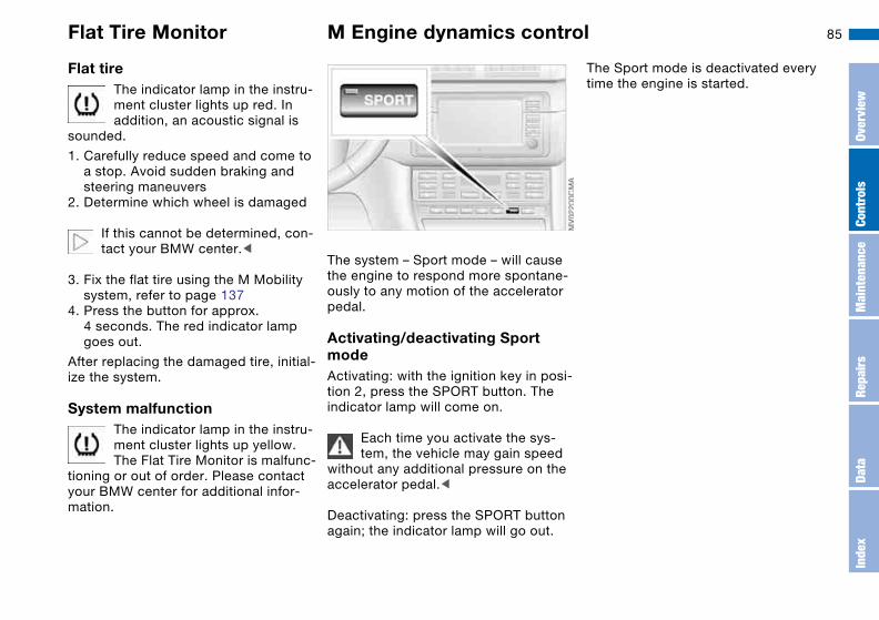
85
Flat tireThe indicator lamp in the instru-ment cluster lights up red. In addition, an acoustic signal is
sounded.
1. Carefully reduce speed and come to a stop. Avoid sudden braking and steering maneuvers
2. Determine which wheel is damaged
If this cannot be determined, con-tact your BMW center.<
3. Fix the flat tire using the M Mobility system, refer to page 137
4. Press the button for approx. 4 seconds. The red indicator lamp goes out.
After replacing the damaged tire, initial-ize the system.
System malfunctionThe indicator lamp in the instru-ment cluster lights up yellow. The Flat Tire Monitor is malfunc-
tioning or out of order. Please contact your BMW center for additional infor-mation.
M Engine dynamics control
The system – Sport mode – will cause the engine to respond more spontane-ously to any motion of the accelerator pedal.
Activating/deactivating Sport modeActivating: with the ignition key in posi-tion 2, press the SPORT button. The indicator lamp will come on.
Each time you activate the sys-tem, the vehicle may gain speed
without any additional pressure on the accelerator pedal.<
Deactivating: press the SPORT button again; the indicator lamp will go out.
The Sport mode is deactivated every time the engine is started.
Flat Tire Monitor
Over
view
Cont
rols
Mai
nten
ance
Repa
irs
Data
Inde
x

86 Brake force display
Brake force display indicates to the road users behind you how hard you are braking.
>Normal braking: the brake lamps among the rear lamps and the center brake lamp light up
>Hard braking or braking with ABS: in addition, the illuminated rear lamp surface is extended, refer to the pic-ture.
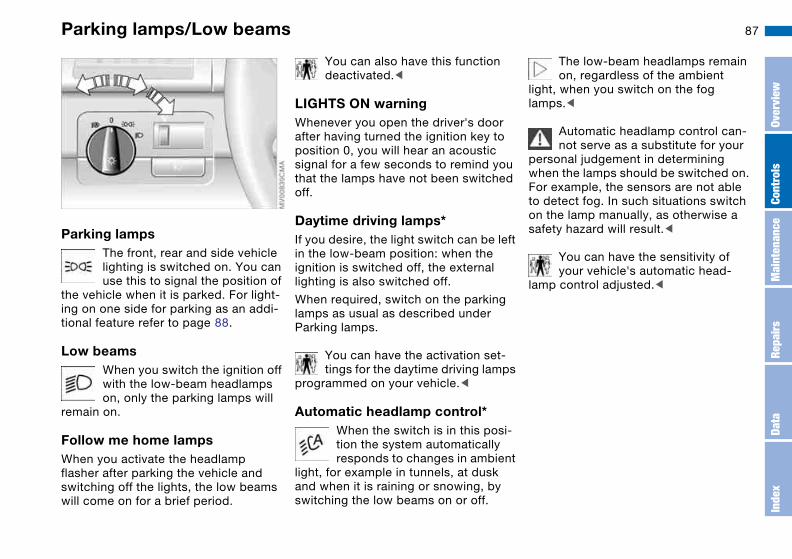
87
Lamps
Parking lamps/Low beams
Parking lampsThe front, rear and side vehicle lighting is switched on. You can use this to signal the position of
the vehicle when it is parked. For light-ing on one side for parking as an addi-tional feature refer to page 88.
Low beamsWhen you switch the ignition off with the low-beam headlamps on, only the parking lamps will
remain on.
Follow me home lampsWhen you activate the headlamp flasher after parking the vehicle and switching off the lights, the low beams will come on for a brief period.
You can also have this function deactivated.<
LIGHTS ON warningWhenever you open the driver's door after having turned the ignition key to position 0, you will hear an acoustic signal for a few seconds to remind you that the lamps have not been switched off.
Daytime driving lamps*If you desire, the light switch can be left in the low-beam position: when the ignition is switched off, the external lighting is also switched off.
When required, switch on the parking lamps as usual as described under Parking lamps.
You can have the activation set-tings for the daytime driving lamps
programmed on your vehicle.<
Automatic headlamp control*When the switch is in this posi-tion the system automatically responds to changes in ambient
light, for example in tunnels, at dusk and when it is raining or snowing, by switching the low beams on or off.
The low-beam headlamps remain on, regardless of the ambient
light, when you switch on the fog lamps.<
Automatic headlamp control can-not serve as a substitute for your
personal judgement in determining when the lamps should be switched on. For example, the sensors are not able to detect fog. In such situations switch on the lamp manually, as otherwise a safety hazard will result.<
You can have the sensitivity of your vehicle's automatic head-
lamp control adjusted.<
Over
view
Cont
rols
Mai
nten
ance
Repa
irs
Data
Inde
x

88 Instrument lighting
Turn the rotary dial with the parking/low beam lamps on to adjust the illumina-tion intensity.
High beams/Standing lamps
1 High beams
2 Headlamp flasher
3 Standing lamps
Standing lamps, left or rightAs an additional feature, you can illumi-nate your vehicle on either side for parking, if you wish to do so:
With the ignition key in position 0, push the lever in the appropriate direction. The lever engages in the turn signal position.
The standing lamps discharge the battery. Avoid using them for
longer periods of time; otherwise, you may not be able to start the engine.<

89Front fog lamps
Tap the button to switch on or off.
The parking lamps or low-beam headlamps must be switched on. The green indicator lamp in
the instrument cluster lights up to indi-cate that the front fog lamps are on.
If the automatic headlamp control is on, the low beams will come on
automatically whenever you activate the front fog lamps.<
Interior lamps
The interior lamps operate automati-cally.
To switch the interior lamps on and off manuallyPress button 1 briefly.
If you want the interior lamps to remain off all the time, press and hold the but-ton for approx. 3 seconds.
Press the button briefly to revert to nor-mal operation.
Front reading lampsSwitch on and off with the button 2 adjacent to each lamp.
Rear reading lampsSwitch on and off with the button adja-cent to each lamp.
In order to prevent battery dis-charge, all of the lamps in the
vehicle are automatically switched off approx. 15 minutes after you turn the ignition key to position 0.<
Over
view
Cont
rols
Mai
nten
ance
Repa
irs
Data
Inde
x

90
Controlling the climate for pleasant driving
Automatic climate control
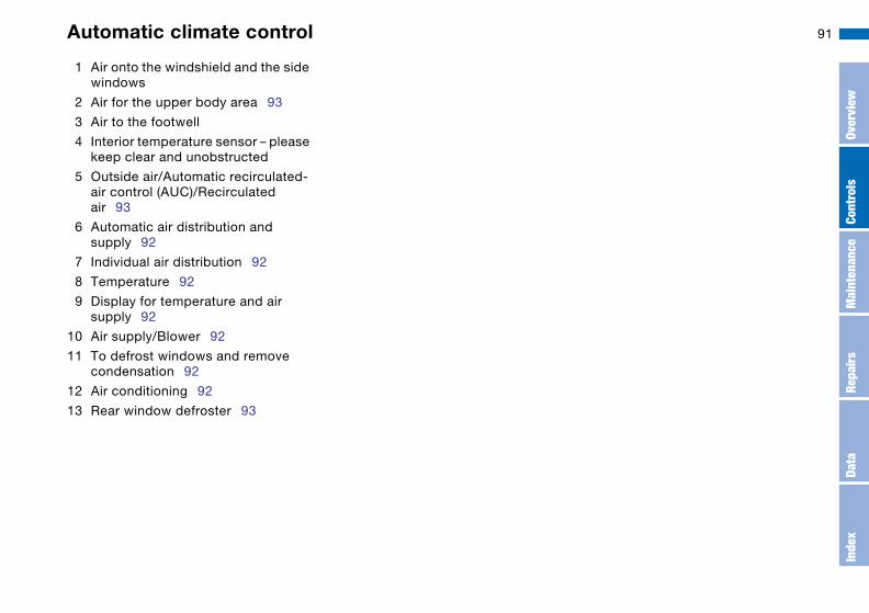
91
1 Air onto the windshield and the side windows
2 Air for the upper body area 93
3 Air to the footwell
4 Interior temperature sensor – please keep clear and unobstructed
5 Outside air/Automatic recirculated-air control (AUC)/Recirculated air 93
6 Automatic air distribution and supply 92
7 Individual air distribution 92
8 Temperature 92
9 Display for temperature and air supply 92
10 Air supply/Blower 92
11 To defrost windows and remove condensation 92
12 Air conditioning 92
13 Rear window defroster 93
Automatic climate control
Over
view
Cont
rols
Mai
nten
ance
Repa
irs
Data
Inde
x

92
Tips for pleasant drivingUse the automatic mode – switch on with AUTO button 6. Select the desired interior temperature.
Detailed setting options are described for you in the following sections.
You can make the settings of your vehicle in such a manner that,
when you unlock the vehicle with the remote control of your personal key, your own personalized setting for the automatic climate control is initiated.<
AUTO programThe AUTO program adjusts the air supply and the air distribu-
tion to the windshield and the side win-dows, towards the upper body and to the footwells, and in addition adapts the temperature to external influences: summer, winter.
The cooling function is automatically switched on when you are using the AUTO program.
Individual air distributionYou can cancel the AUTO pro-gram by selecting specific dis-tribution patterns to suit your own individual requirements.
While the AUTO program is then deacti-vated, the automatic airflow control remains in operation. Air flows onto the windows , toward the upper body , and into the footwell . You can reactivate the automatic air supply by pressing the AUTO button.
TemperatureThe interior temperature that appears in the display panel is a general figure intended for refer-
ence purposes. We recommend 727/ +226 as a comfortable setting, even if the air conditioning is on. When you start the vehicle, the system ensures that the selected temperature is reached as quickly as possible. It then maintains this temperature, regardless of the season.
To select the units of measure 7/6 of the display, refer to page 79.
Air supply/BlowerBy pressing the upper or lower button, you can vary the air sup-ply. This deactivates the auto-
matic air supply – the AUTO display dis-appears from the panel. Nevertheless,
the automatic air distribution remains unchanged. You can reactivate the automatic air supply by pressing the AUTO button.
When the lowest blower speed is set and you press the lower button, all of the displays are canceled: the blower, heating and air conditioner are switched off, and the air supply is stopped. You can reactivate the system by pressing any button for the auto-matic climate control.
To defrost windows and remove condensation
This program quickly removes ice and condensation from the
windshield and the side windows.
Air conditioningThe air is cooled and dehumidi-fied and – depending on the
temperature setting – rewarmed.
Depending on the weather, the wind-shield may fog over briefly when the engine is started. Air conditioning helps prevent the windows from fogging up.
The cooling function is automatically switched on when you are using the AUTO program.
Automatic climate control
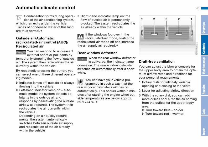
93
Condensation forms during opera-tion of the air conditioning system,
which then exits under the vehicle. Traces of condensed water of this kind are thus normal.<
Outside air/Automatic recirculated-air control (AUC)/ Recirculated air
You can respond to unpleasant external odors or pollutants by
temporarily stopping the flow of outside air. The system then recirculates the air currently within the vehicle.
By repeatedly pressing the button, you can select one of three different operat-ing modes.
> Indicator lamps off: outside air always flowing into the vehicle
>Left-hand indicator lamp on – auto-matic mode: the system detects pol-lutants in the outside air and responds by deactivating the outside airflow as required. The system then recirculates the air currently within the vehicle.Depending on air quality require-ments, the system automatically switches between outside air supply and recirculation of the air already within the vehicle
>Right-hand indicator lamp on: the flow of outside air is permanently blocked. The system recirculates the air already within the vehicle.
If the windows fog over in the recirculated-air mode, switch the
recirculated-air mode off and increase the air supply as required.<
Rear window defrosterWhen the rear window defroster is activated, the indicator lamp
comes on. The rear window defroster switches off automatically after a short while.
You can have your vehicle pro-grammed in such a way that the
rear window defroster switches on automatically. This occurs within 5 min-utes after starting the engine when out-side temperatures are below approx. 397/+46.<
Draft-free ventilationYou can adjust the blower controls for the upper body area to obtain the opti-mum airflow rates and directions for your personal requirements:
1 Rotary dials for infinitely variable opening and closing of the vents
2 Lever for adjusting airflow direction
3 With the rotary dial, you can add more or less cool air to the air coming from the outlets for the upper body area:>Turn toward blue – colder>Turn toward red – warmer.
Automatic climate control
Over
view
Cont
rols
Mai
nten
ance
Repa
irs
Data
Inde
x
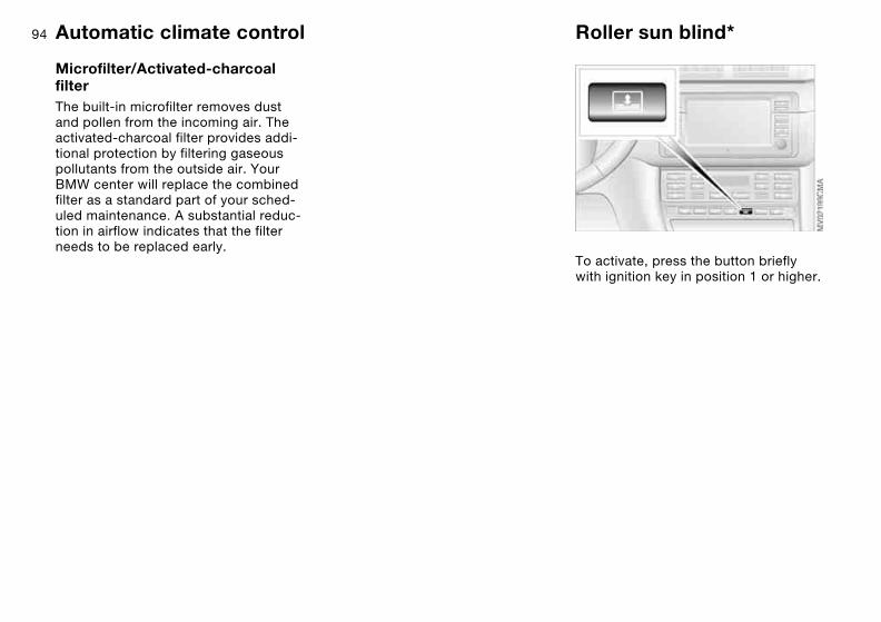
94
Microfilter/Activated-charcoal filterThe built-in microfilter removes dust and pollen from the incoming air. The activated-charcoal filter provides addi-tional protection by filtering gaseous pollutants from the outside air. Your BMW center will replace the combined filter as a standard part of your sched-uled maintenance. A substantial reduc-tion in airflow indicates that the filter needs to be replaced early.
Roller sun blind*
To activate, press the button briefly with ignition key in position 1 or higher.
Automatic climate control

95
Interior conveniences
Premium sound system*
Harman Kardon premium sound systemWhen the system is activated, the impression of a significantly larger pas-senger compartment is created at all seating areas, together with an improvement of the stereo effect.
The system responds to poor reception conditions by repeatedly alternating between the stereo and monophonic modes. You should then switch the sys-tem off.
Glove compartment
To openPull the handle. The glove compartment will light up.
To closeFold up cover.
To prevent injury in the event of an accident, close the glove com-
partment immediately after use.<
To lockLock with one of the master keys. A master key can also be used for unlock-ing.
Over
view
Cont
rols
Mai
nten
ance
Repa
irs
Data
Inde
x

96
If – for example for valet parking – you turn over only your spare key,
refer to page 28, then access to the glove compartment and to the luggage compartment is not possible.<
Storage compartments
Front center armrest*To open: press the button and fold up.
Additional compartments and netsYou will find additional storage areas in the doors and in the center console above the ashtray. Storage nets are located on the backrests of the front seats.
Beverage holders, coin boxA coin box and two beverage holders are provided in the center console.
Do not place any glass containers in the beverage holders, as this
increases the risk of injury in the event of an accident.<
Glove compartment

97
Rear center armrestYou will find a beverage holder in the rear center armrest.
Opening the beverage holder: press.
Storage package*For your convenience, there are:
>Two flip-out sockets on the rear cen-ter console
>An eyeglasses storage compart-ment*, not shown, in the center con-sole.
Microphone*
Hands-free systemIn vehicles with telephone provisions* or the voice command system*, the cover for the hands-free microphone is located in the roof lining near the inte-rior lamp.
For additional information on using your car phone, cellular phone or voice com-mand system, refer to the respective separate Owner's Manual.
Storage compartments
Over
view
Cont
rols
Mai
nten
ance
Repa
irs
Data
Inde
x

98 Ashtray, front*
To emptyPress on the edge of the open cover. you can now pull the ashtray upward for removal.
Extinguishing cigarettesTap off the ash and gently press the tip into the funnel.
Cigarette lighterHold or touch the hot cigarette lighter by the knob only. Holding
or touching it in other areas could result in burns.The cigarette lighter remains opera-tional when the ignition key has been removed. For this reason, children should never be left in the vehicle unat-tended.<
Press lighter 1 in. As soon as the lighter jumps back out, it can be removed.
Power socketThe cigarette lighter socket can be used as a power socket for a flashlight, car vacuum cleaner, etc., up to a rating of approx. 200 watts at 12 volts. Do not damage the socket by inserting plugs of the wrong shape or size. In vehicles with a non-smoker's equipment pack-age, the socket is covered by a remov-able cap.
Ashtray, rear*
To emptyPress on the edge of the open cover in the opening direction: you can now pull the ashtray upward for removal.
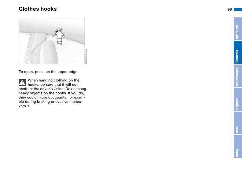
99Clothes hooks
To open, press on the upper edge.
When hanging clothing on the hooks, be sure that it will not
obstruct the driver's vision. Do not hang heavy objects on the hooks. If you do, they could injure occupants, for exam-ple during braking or evasive maneu-vers.<
Over
view
Cont
rols
Mai
nten
ance
Repa
irs
Data
Inde
x

100
Loading and transporting
Through-loading system
Folding the rear backrest1. Pull the corresponding lever to
release
2. The backrest moves forward slightly when released. Reach into the gap and fold it down.
When folding the backrest back into its original position always
ensure that the detent engages securely. A loose backrest might fail to prevent cargo from entering the pas-senger compartment during sudden braking or evasive maneuvers, posing a potential hazard to occupants.<
Rear center 3-point safety belt*You can roll up the rear 3-point belt before folding back the through-loading system:
>Retracting the 3-point-safety belt: Loosen the safety belt and insert the buckle latch into the support mount provided on the rear window shelf.

101Ski bag*
The ski bag allows the safe and clean transport of up to 4 pairs of standard skis or up to two snowboards.
The length of the ski bag and the addi-tional space provided in the luggage compartment make it possible to carry skis up to 6 ft 10 in / 2.10 m long. Because of the tapered shape of the bag, only two pairs of skis longer than 6 ft 10 in / 2.10 m can be carried.
Loading1. Fold the center armrest outward.
Loosen the trim from the upper Velcro® fastener and place it on the armrest
2. Press the button downward – see arrow 1 – and fold the cover forward
3. Extend the ski bag between the front seats. The zipper provides conve-nient access to stored items. It may be opened to allow the ski bag to dry
4. Press the button – see arrow 2: this releases the cover panel in the lug-gage compartment.
To store the ski bag, perform the above steps in reverse sequence.
Securing cargoAfter loading, secure the ski bag and its contents. To do so, tighten the retaining strap at the tensioning buckle.
Be sure to secure the ski bag in this way, as it could otherwise
injure occupants, for example during braking or evasive maneuvers.Be sure that the skis are clean before loading them into the bag. Be careful to avoid damage from sharp edges.<
Over
view
Cont
rols
Mai
nten
ance
Repa
irs
Data
Inde
x

102 Cargo loading
Avoid overloading the vehicle so that the permitted load on the tires
is not exceeded. Overloading can lead to overheating and internal tire damage. This can result in a sudden loss of tire inflation pressure.<
Determining the maximum load1. Locate the following statement on
your vehicle's placard*:
The combined weight of occu-pants and cargo should never
exceed XXX kg or YYY lbs., as this could otherwise result in damage to the vehicle or unstable driving conditions.<
2. Determine the combined weight of the driver and passengers that will be riding in your vehicle
3. Subtract the combined weight of the driver and passengers from XXX kilograms or YYY pounds
4. The resulting figure equals the avail-able amount of cargo and luggage load capacity.For example, if the YYY amount equals 1,000 lbs. and there will be five 150 lbs. passengers in your vehi-cle, the amount of available cargo and luggage load capacity is 250 lbs.:1,000 lbs. minus 750 lbs. = 250 lbs.
5. Determine the combined weight of luggage and cargo being loaded on the vehicle. That weight may not safely exceed the available cargo and luggage load capacity calculated in Step 4
6. If your vehicle will be towing a trailer, load from your trailer will be trans-fered to your vehicle. Consult the manual for transporting a trailer to determine how this may reduce the available cargo and luggage load capacity of your vehicle.
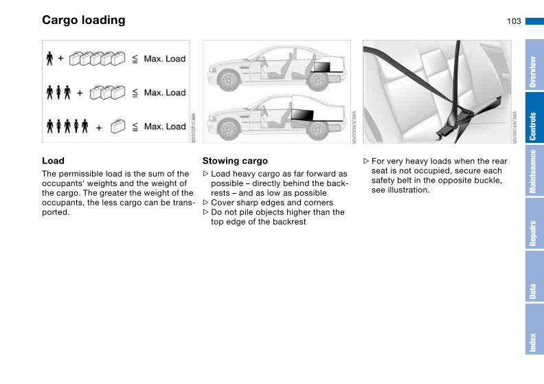
103
LoadThe permissible load is the sum of the occupants' weights and the weight of the cargo. The greater the weight of the occupants, the less cargo can be trans-ported.
Stowing cargo>Load heavy cargo as far forward as
possible – directly behind the back-rests – and as low as possible
>Cover sharp edges and corners>Do not pile objects higher than the
top edge of the backrest
>For very heavy loads when the rear seat is not occupied, secure each safety belt in the opposite buckle, see illustration.
Cargo loading
Over
view
Cont
rols
Mai
nten
ance
Repa
irs
Data
Inde
x
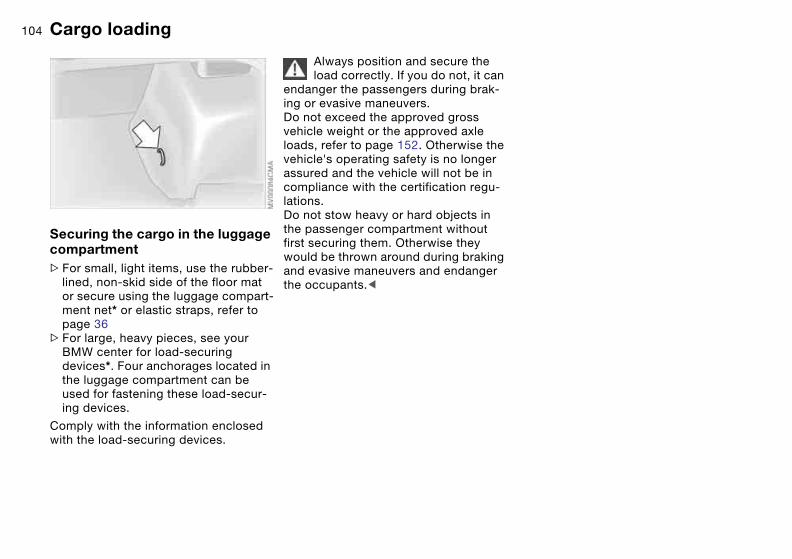
104
Securing the cargo in the luggage compartment >For small, light items, use the rubber-
lined, non-skid side of the floor mat or secure using the luggage compart-ment net* or elastic straps, refer to page 36
>For large, heavy pieces, see your BMW center for load-securing devices*. Four anchorages located in the luggage compartment can be used for fastening these load-secur-ing devices.
Comply with the information enclosed with the load-securing devices.
Always position and secure the load correctly. If you do not, it can
endanger the passengers during brak-ing or evasive maneuvers.Do not exceed the approved gross vehicle weight or the approved axle loads, refer to page 152. Otherwise the vehicle's operating safety is no longer assured and the vehicle will not be in compliance with the certification regu-lations.Do not stow heavy or hard objects in the passenger compartment without first securing them. Otherwise they would be thrown around during braking and evasive maneuvers and endanger the occupants.<
Cargo loading
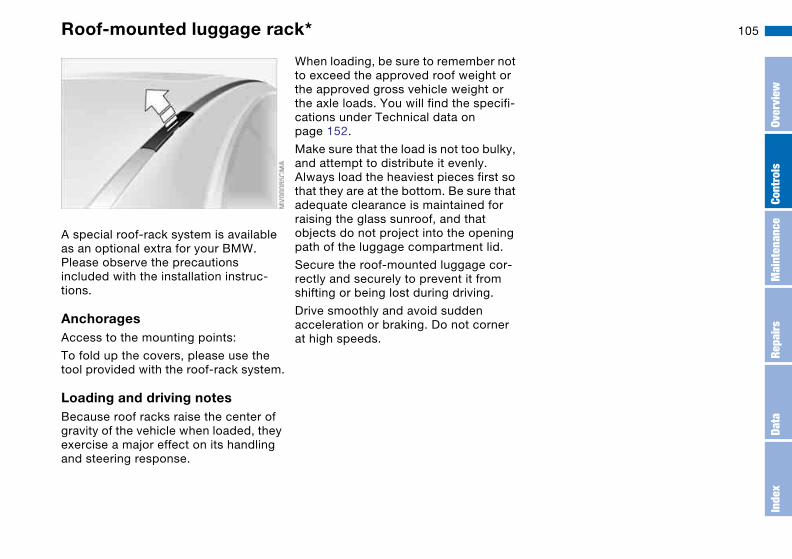
105Roof-mounted luggage rack*
A special roof-rack system is available as an optional extra for your BMW. Please observe the precautions included with the installation instruc-tions.
AnchoragesAccess to the mounting points:
To fold up the covers, please use the tool provided with the roof-rack system.
Loading and driving notesBecause roof racks raise the center of gravity of the vehicle when loaded, they exercise a major effect on its handling and steering response.
When loading, be sure to remember not to exceed the approved roof weight or the approved gross vehicle weight or the axle loads. You will find the specifi-cations under Technical data on page 152.
Make sure that the load is not too bulky, and attempt to distribute it evenly. Always load the heaviest pieces first so that they are at the bottom. Be sure that adequate clearance is maintained for raising the glass sunroof, and that objects do not project into the opening path of the luggage compartment lid.
Secure the roof-mounted luggage cor-rectly and securely to prevent it from shifting or being lost during driving.
Drive smoothly and avoid sudden acceleration or braking. Do not corner at high speeds.
Over
view
Cont
rols
Mai
nten
ance
Repa
irs
Data
Inde
x

106
107
Overview
Controls and features
Operation, maintenance
Owner service procedures
Technical data
Index
Over
view
Cont
rols
Mai
nten
ance
Repa
irs
Data
Inde
x
108
Special operating instructions
Break-in procedures
To ensure that your vehicle provides maximum economy throughout a long service life, we request that you observe the following suggestions.
Because of its engineering design, the BMW M3 is an especially high-
quality vehicle. It is in your best interest to follow the break-in tips very closely. Doing this, you will create the basis for a long, optimum service life.<
Engine and differentialUp to 1,250 miles/2,000 km:
Drive at varying engine and road speeds, but do not exceed an engine speed of 5,500 rpm or a road speed of 105 mph / 170 km/h.
Obey your local and state maximum speed limits.
Do not depress the accelerator pedal to the full-throttle position.
Vehicles with SMG Drivelogic, refer to page 69: do not use Drivelogic pro-grams 5 or 6 or launch control during the break-in period.
>Following the break-in inspection at 1,250 miles/2,000 km, you can grad-ually increase engine or road speeds.
TransmissionThe transmission will begin to function optimally after approx. 300 miles/500 km. Shift gears cau-tiously during this period and do not exceed an engine speed of 5,500 rpm.
Vehicles with SMG Drivelogic, refer to page 69: do not use Drivelogic pro-grams 5 or 6 or launch control during the break-in period.
TiresDue to technical factors associated with their manufacture, tires do not achieve their full traction potential until an initial break-in period has elapsed. Thus drive with extra care during the initial 200 miles/300 km.
Obey your local and state maximum speed limits.
Brake systemApprox. 300 miles/500 km must elapse before the brake pads and rotors achieve the optimal pad-surface and wear patterns required for trouble-free operation and long service life later on.
To break in the separate parking brake drums, apply the parking brake lightly when coasting to a standstill, e.g. at a traffic signal, provided that traffic condi-tions permit to do so.
To avoid corrosion, repeat this proce-dure from time to time.
The brake lamps do not come on when the parking brake is set.
Vacuum for the brake system servo unit on your BMW is available only when the engine is running. When you move the vehicle with the engine off – when tow-ing, for example – substantially higher levels of pedal force will be required to brake the vehicle.<
ClutchThe clutch will also begin to function optimally after about 300 miles/500 km. Drive cautiously during this break-in period and do not press the clutch or shift at high engine speeds.
After replacing partsFollow the same break-in procedures if any of the components mentioned above have to be replaced in the future.

109General driving notes
Hot exhaust systemHigh temperatures occur with every vehicle equipped with a cat-
alytic converter. Heat shields are installed adjacent to some sections of the exhaust system. Never remove these shields; do not apply undercoat-ing to their surfaces. When driving, standing at idle and parking the vehicle, take care to avoid contact between the hot exhaust system and flammable materials, e.g. hay, leaves, grass, etc. Such contact could lead to a fire, resulting in serious personal injury and property damage.<
When the vehicle is parkedCondensation forms in the automatic climate control system during opera-tion, which then exits under the vehicle. Traces of condensed water of this kind are thus normal.
Before driving through a car washFold in the exterior mirrors manually because they could otherwise be dam-aged due to the width of the vehicle.
HydroplaningWhen driving on wet or slushy roads, reduce road speed. If you
do not, a wedge of water can form between tire and road surface. This phenomenon is referred to as hydro-planing, and can lead to partial or com-plete loss of traction, vehicle control and braking effectiveness.<
The risk of hydroplaning increases as the tread depth of the tires decreases, refer also to Tire tread on page 116.
Driving through waterDo not drive through water on the road if it is deeper than 1 ft/30 cm,
and then only at walking speed. Other-wise, the vehicle's engine, the electrical systems and the transmission may be damaged.<
Braking safelyYour BMW is equipped with ABS as a standard feature. If you are in a situa-tion which requires full braking, it is best to brake using maximum brake pressure: panic stop. Since the vehicle maintains steering responsiveness, you can avoid possible obstacles with a minimum of steering effort.
Pulsation at the brake pedal combines with sounds from the hydraulic circuits to indicate to the driver that ABS is in its active mode.
Do not rest your foot on the brake pedal while driving. Otherwise,
even light but consistent pedal pres-sure can lead to high temperatures, brake wear and possibly even brake failure.<
Wet roads:
If the roads are wet or if there is heavy rain, it is advisable to gently press the brakes for a brief moment every few miles/kilometers. Watch traffic condi-tions to ensure that this maneuver does not endanger other road users. The heat generated in this process helps dry the pads and rotors. Immediate braking force is then available if neces-sary.
Over
view
Cont
rols
Mai
nten
ance
Repa
irs
Data
Inde
x

110
Inclines:
To prevent overheating and, as a result, diminished braking effec-
tiveness, drive down long or steep downhill grades in a gear which requires the least braking. Otherwise, even light but consistent pedal pres-sure can lead to high temperatures, brake wear and possibly even brake failure.<
The braking power of the engine can be further enhanced by downshifting the automatic transmission in manual mode, if necessary, into first gear. This helps avoid placing excessive loads on the brake system.
Do not coast with the clutch depressed or with the transmis-
sion or selector lever in Neutral. Do not coast with the engine switched off. Oth-erwise, the engine provides no braking effect while the transmission is in idling position, and there is no power-assist for braking or steering when the engine is off.Floor mats, floor carpets or other objects must not be in the area near the brake or accelerator pedal, as this could impair the movement of the ped-als.<
Corrosion on the brake rotorsLimited vehicle use, extended periods with the vehicle parked or in storage, and operating conditions in which brak-ing is restricted to gentle, low-pressure applications will all increase the ten-dency for corrosion to form on the rotors and contamination to accumulate on the brake pads. This occurs because the minimal pressure which must be exerted by the pads to clean the rotors by brake applications is not reached.
Corrosion on brake rotors is signaled by a pulsation during initial braking that usually does not disappear even after extended subsequent braking.
Brake padsFor your own safety: use only brake pads which BMW has
approved for your specific vehicle model. BMW cannot evaluate non-approved brake pads to determine if they are suitable for use, and therefore cannot ensure the operating safety of the vehicle if they are installed.<
Portable phone in the vehicleBMW advises against using mobile equipment, e.g. cellular
phones, inside the vehicle without con-necting them directly to an outside antenna. Otherwise, it cannot be ruled out that vehicle electronics and the mobile equipment interfere with one another. In addition, it is not ensured that the radio waves emitted during transmission are directed outside of the vehicle interior.<
General driving notes
111Antilock Brake System (ABS)
The conceptABS keeps the wheels from locking during braking, thereby enhancing active driving safety.
Braking with ABSIf you are in a situation that requires full braking, you will exploit the full benefits of the ABS system if you apply maxi-mum pedal pressure: panic stop. Since the vehicle maintains steering respon-siveness, you can avoid possible obsta-cles with a minimum of steering effort.
Pulsation at the brake pedal combines with sounds from the hydraulic circuits to indicate to the driver that ABS is in its active mode.
Dynamic Brake Control (DBC)DBC is included in the DSC, refer to page 82.
If you apply the brakes rapidly, this sys-tem automatically generates maximum braking force boost and thus helps to achieve the shortest possible braking distance in panic braking situations. All of the benefits of the ABS are exploited under these circumstances.
Do not reduce the pressure on the brake pedal for the duration of the brake application. When the brake pedal is released, the DBC is deacti-vated.
Cornering Brake Control (CBC)CBC is an advanced engineering design of the ABS. When braking while cornering at high speed or braking dur-ing high lateral acceleration, or when braking during a lane change, vehicle stability is improved and steering response is enhanced.
Over
view
Cont
rols
Mai
nten
ance
Repa
irs
Data
Inde
x

112
Wheels and tires
Tire inflation pressure
Information for your safetyIt is not merely the tire's service life, but also driving comfort and, above all else, driving safety that depend on the condi-tion of the tires and the maintenance of the specified tire pressure.
Checking tire pressuresOnly check the tire inflation pressures of cold tires. This means after driving a maximum of 1.25 miles/2 km or after the vehicle has been parked for at least 2 hours. Warm tires have higher infla-tion pressures.
Check tire inflation pressures reg-ularly and correct them if neces-
sary: at least twice a month and before beginning a longer trip. Otherwise, incorrect tire pressures can cause driv-ing instability or tire damage, ultimately resulting in accidents. Do not drive on a deflated, i.e. flat, tire. A flat tire greatly impairs steering and braking response, and can lead to complete loss of con-trol over the vehicle.<
After correcting the tire inflation pres-sure, reinitialize the Flat Tire Monitor, refer to page 84.
Inflation pressures for original tiresTire pressures for the standard tires of your vehicle are shown on the driver's door post, visible when the door is open.
The inflation pressures apply to BMW-approved tire sizes and recommended tire brands. Your BMW center will be glad to supply this information.
Inflation pressures for other tire sizesThe following tire pressure table shows all tire pressures for the given tire sizes at ambient temperature.

113
BMW TiresAll pressure specifications inthe table are indicated in psi/kilopascal with cold tires –cold = ambient temperature
M3
225/45 ZR 18 33/230 – 41/280 –
255/40 ZR 18 – 35/240 – 48/330
225/45 ZR 18225/40 ZR 19
33/230 – 41/280 –
255/35 ZR 19 – 35/240 – 48/330
225/45 R 17 91 H M+S 33/230 38/260 36/250 46/320
225/40 R 18 92 V M+S 36/250 38/260 39/270 51/350
Tire inflation pressure
Over
view
Cont
rols
Mai
nten
ance
Repa
irs
Data
Inde
x
114 Tire code
Knowing the tire code on the tire side-wall makes it easier to correctly choose and identify your tires.
Tire sizeE.g. 205/60 R 15 91 W
205 = Nominal width in mm
60 = Cross-sectional ratio in %
R = Radial belt construction
15 = Rim diameter in inches
91 = Load index, not on ZR tires
W = Speed rating, in front of the R on ZR tires
Speed ratingQ = up to 100 mph (160 km/h)
T = up to 118 mph (190 km/h)
H = up to 130 mph (210 km/h)
V = up to 150 mph (240 km/h)
W = up to 167 mph (270 km/h)
Y = up to 186 mph (300 km/h)
Tire Identification NumberTires with DOT codes comply with the guidelines of the U.S. Department of Transportation.
DOT code:
E.g. DOT xxxx xxx 3204
xxxx = Manufacturer's code for tire brand
xxx = Tire size and tire version
3204 = Tire age
Tire ageThe date on which the tire was manu-factured is indicated by the code on the sidewall:
DOT … 3204 indicates that the tire was manufactured in week 32 of the year 2004.
BMW recommends the replacement of all tires when they are no more than 6 years old, even if a tire life of 10 years is possible.
Uniform Tire Quality GradingQuality grades can be found where applicable on the tire sidewall between tread shoulder and maximum section width. For example:
Tread wear 200 Traction AA
Temperature A
DOT quality gradesTread wear
Traction AA A B C
Temperature A B C
All passenger car tires must con-form to Federal Safety Require-
ments in addition to these grades.<
Tread wearThe tread wear grade is a comparative rating based on the wear rate of the tire when tested under controlled condi-tions on a specified government test course.
For example, a tire graded 150 would wear one and one-half – 1 1/2 – times as well on the government course as a tire graded 100. The relative performance of tires depends upon the actual condi-tions of their use, however, and may depart significantly from the norm due to variations in driving habits, service practices and differences in road char-acteristics and climate.
TractionThe traction grades, from highest to lowest, are AA, A, B, and C.
115
Those grades represent the tire's ability to stop on wet pavement as measured under controlled conditions on speci-fied government test surfaces of asphalt and concrete. A tire marked C may have poor traction performance.
The traction grade assigned to this tire is based on straight-
ahead braking traction tests, and does not include acceleration, cornering, hydroplaning, or peak traction charac-teristics.<
TemperatureThe temperature grades are A, the highest, B, and C, representing the tire's resistance to the generation of heat and its ability to dissipate heat when tested under controlled condi-tions on a specified indoor laboratory test wheel.
Sustained high temperature can cause the material of the tire to degenerate and reduce tire life, and excessive tem-perature can lead to sudden tire failure. The grade C corresponds to a level of performance which all passenger car tires must meet under the Federal Motor Vehicle Safety Standard No. 109.
Grades B and A represent higher levels of performance on the laboratory test wheel than the minimum required by law.
The temperature grade for this tire is established for a tire that is
properly inflated and not overloaded. Excessive speed, under-inflation, or excessive loading, either separately or in combination, can cause heat buildup and possible tire failure.<
M+SWinter and all-season tires. These have better winter driving properties than summer tires.
Tire condition
Wheel/tire damageInspect your tires frequently for signs of damage, foreign objects and tread wear, and check tread depth.
Due to low-profile tires, please note that wheels, tires and sus-
pension parts are more susceptible to road hazard and consequential dam-ages.Unusual vibrations encountered during normal vehicle operation can indicate tire failure or some other vehicle defect. This type of problem can be caused by contact with curbs, etc. This is also true for irregularities in the vehicle's han-dling characteristics, such as a pro-nounced tendency to pull to the left or right.Should this occur, respond by immedi-ately reducing your speed. Proceed carefully to the nearest BMW center or professional tire center, or have the vehicle towed there. Tire damage, up to and including blowouts, can endanger the lives of both the vehicle occupants and other road users.<
Tire code
Over
view
Cont
rols
Mai
nten
ance
Repa
irs
Data
Inde
x

116
Tire treadTread depth should not be allowed to go below 1/8 in / 3 mm, even though European legislation, for example, requires a mimimum tread depth of only 1/16 in / 1.6 mm. Below 1/8 in / 3 mm tread depth, there is a great risk of hydroplaning, even at relatively moder-ate speeds and with only small amounts of water on the road.
At tread depths below approx. 3/16 in / 4 mm, tire performance under winter driving conditions deteriorates noticeably. Worn tires should therefore be replaced for safety considerations.
Tread wear indicators in the tread-groove base, see arrow, are distributed around the wheel circumference and are labeled on the tire sidewall with
TWI, Tread Wear Indicator. At a tread depth of 1/16 in / 1.6 mm, the indica-tors signal that the legally permissible wear limit has been reached.
New wheels and tires
Have new wheels and tires mounted only by a BMW center or
specialized tire shop that works according to BMW requirements with appropriately trained personnel. Work that is improperly carried out could result in consequential damage and pose safety hazards.<
Ask your BMW center for details con-cerning the correct wheel and tire com-bination. Have the wheels balanced each time a wheel or tire has been replaced.
The correct wheel and tire combination also affects different systems such as ABS or DSC. The function of these sys-tems is impaired if improper wheel and tire combinations are used.
BMW advises against using retreaded tires, as driving safety
could otherwise be impaired. The rea-son for this are the possibly different tire casing structures involved, some of which may be greatly aged, factors which can lead to a decrease in durabil-ity.<
Tire condition
117
The correct wheels and tiresBMW recommends using only wheels and tires that have been
tested and approved by BMW for the particular vehicle model, as otherwise body contact and serious accidents can result despite the use of the same nom-inal size, e.g. due to manufacturing tol-erances. If non-approved wheels and tires are used, BMW cannot evaluate their suitability, and therefore cannot be held liable for driving safety.<
To maintain good handling and vehicle response, use only tires of a single brand and tread configuration. After a flat tire, have the previous wheel and tire combination restored as soon as possible.
Recommended tire sizes and brandsFor each tire size, certain tire brands have been tested, classified as road-safe and approved by BMW. You can find out about these from a professional tire center, preferably your BMW cen-ter. Observe any country-specific regu-lations, e.g. on making a corresponding entry in the vehicle documents.
The factory-approved radial belt tires are matched to your vehicle and pro-vide optimum safety and driving com-fort when used properly.
Special characteristics of winter tiresBMW recommends the use of winter tires for operation under winter road conditions. While all-season tires with M+S designation provide better winter traction than summer tires, they gener-ally do not achieve the full performance of winter tires.
Observing speed ratingsNever exceed the maximum speed for which the winter tires
are rated. Unprofessional attempts by laymen to service tires can lead to dam-age and accidents. Have this work per-formed by skilled professionals only. The technicians at your BMW center will be glad to assist you with the required professional knowledge and specialized equipment.<
StorageAlways store tires in a cool, dry place. Store them away from light whenever possible. Protect the tires against con-tact with oil, grease and fuel. Do not exceed the maximum tire inflation pres-sures specified on the tire sidewall.
New wheels and tires
Over
view
Cont
rols
Mai
nten
ance
Repa
irs
Data
Inde
x
118 Snow chains*
Only certain snow chains have been tested by BMW and determined and approved as roadworthy. Consult your BMW center for more information. BMW recommends using only these approved fine-link snow chains. Use them in pairs on winter tires, but only on both rear wheels.
Comply with all manufacturer's safety precautions when mounting the chains. Do not exceed a maximum speed of 30 mph / 50 km/h when using snow chains.
After mounting or removing snow chains, always reinitialize the sequential M gearbox with Drivelogic, refer to page 70.
It is not possible to mount snow chains on tires with 18-inch and
19-inch wheels.Deactivate the Flat Tire Monitor when using snow chains. Malfunction warn-ings and undetected losses in pressure are a possibility when driving with snow chains.When driving with snow chains, it may be useful to deactivate DSC, refer to page 83.<
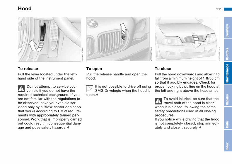
119
In the engine compartment
Hood
To releasePull the lever located under the left-hand side of the instrument panel.
Do not attempt to service your vehicle if you do not have the
required technical background. If you are not familiar with the regulations to be observed, have your vehicle ser-viced only by a BMW center or a shop that works according to BMW require-ments with appropriately trained per-sonnel. Work that is improperly carried out could result in consequential dam-age and pose safety hazards.<
To openPull the release handle and open the hood.
It is not possible to drive off using SMG Drivelogic when the hood is
open.<
To closePull the hood downwards and allow it to fall from a minimum height of 1 ft/30 cm so that it audibly engages. Check for proper locking by pulling on the hood at the left and right above the headlamps.
To avoid injuries, be sure that the travel path of the hood is clear
when it is closed, following the same safety precautions used in all closing procedures.If you notice while driving that the hood is not completely closed, stop immedi-ately and close it securely.<
Over
view
Cont
rols
Mai
nten
ance
Repa
irs
Data
Inde
x

120 Engine compartment essentials

121
1 Filler neck for headlamp and wind-shield washer cleaning system 122
2 Coolant expansion tank 124
3 Auxiliary terminal for jump-starting – positive terminal 143
4 Engine oil filler neck 123
5 Expansion tank for SMG Drivelogic hydraulic unit, checking and possible refilling by your BMW center 66
6 Engine oil dipstick 122
7 Filler neck for brake fluid 125
Engine compartment essentials
Over
view
Cont
rols
Mai
nten
ance
Repa
irs
Data
Inde
x

122 Washer fluids
Headlamp* and windshield washer systemCapacity approx. 5.6 US quarts/5.3 liters.
Fill with water and, if required, with a washer antifreeze additive according to manufacturer's recommendations.
We recommend that you mix the washer fluid before adding it to
the reservoir.<
Antifreeze agents for the washer fluid are highly flammable. For this
reason, keep them away from sources of flame and store them only in their closed original containers. Store them inaccessible to children. Comply with the instructions on the containers.<
Engine oil
Checking the oil level1. Park the vehicle on a level surface2. Switch the engine off after it has
reached normal operating tempera-ture
3. After approx. 1 minute, pull the dip-stick out and wipe it off with a clean lint-free cloth, paper towel, or similar material
4. Carefully push the dipstick all the way into the guide tube and pull it out again
5. The oil level should be between the two marks on the dipstick.
As with fuel economy, oil consumption is directly influenced by your driving style and vehicle operating conditions.
The oil volume between the two marks on the dipstick corresponds to approx. 1.4 US quarts/1.3 liters.

123
Adding engine oilOnly add engine oil when the oil level has dropped to just above the lower mark on the dipstick.
Do not fill beyond the upper mark on the dipstick. Excess oil will damage the engine.
Before checking the engine oil level after topping up, restart the engine and allow it to run to obtain a correct dis-play. Then proceed as described under Checking the oil level.
Continuous exposure to used oil has caused cancer in laboratory
testing. For this reason, thoroughly wash any areas of skin that come into contact with oil using soap and water.Store oils, grease and similar materials so that they are inaccessible to chil-dren. Comply with warning labels and information on containers.<
Comply with the applicable envi-ronmental laws regulating the dis-
posal of used oil.<
Recommendation: have the oil changed at your BMW center.
Specified engine oilsThe quality of the engine oil is extremely important for the function and life of an engine. Based on exten-sive testing, BMW has approved only certain grades of engine oil.
Use only oils approved for your vehicle model.
Ask your BMW center for details concerning oils that have been
approved. You can also call BMW of North America toll-free at 1-800-831-1117 or visit this website: www.bmwusa.com to obtain this infor-mation.<
BMW engines are designed to operate without oil additives; the
use of additives could even lead to damage in some cases.<
Alternative oil typesIf a High Performance Synthetic Oil approved by BMW should be unavail-able, you may use small volumes of other oils for topping up between oil changes. The following data must appear on the packaging:
>Viscositypreferred: SAE 10W-60alternative: SAE 5W-40 or SAE 10W-40
>Specificationspreferred: API SJ/CFalternative: API SJ – also SK, SL, S etc.
Engine oil
Over
view
Cont
rols
Mai
nten
ance
Repa
irs
Data
Inde
x
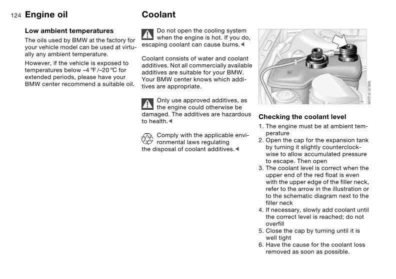
124
Low ambient temperaturesThe oils used by BMW at the factory for your vehicle model can be used at virtu-ally any ambient temperature.
However, if the vehicle is exposed to temperatures below –47/–206 for extended periods, please have your BMW center recommend a suitable oil.
Coolant
Do not open the cooling system when the engine is hot. If you do,
escaping coolant can cause burns.<
Coolant consists of water and coolant additives. Not all commercially available additives are suitable for your BMW. Your BMW center knows which addi-tives are appropriate.
Only use approved additives, as the engine could otherwise be
damaged. The additives are hazardous to health.<
Comply with the applicable envi-ronmental laws regulating
the disposal of coolant additives.<
Checking the coolant level1. The engine must be at ambient tem-
perature2. Open the cap for the expansion tank
by turning it slightly counterclock-wise to allow accumulated pressure to escape. Then open
3. The coolant level is correct when the upper end of the red float is even with the upper edge of the filler neck, refer to the arrow in the illustration or to the schematic diagram next to the filler neck
4. If necessary, slowly add coolant until the correct level is reached; do not overfill
5. Close the cap by turning until it is well tight
6. Have the cause for the coolant loss removed as soon as possible.
Engine oil
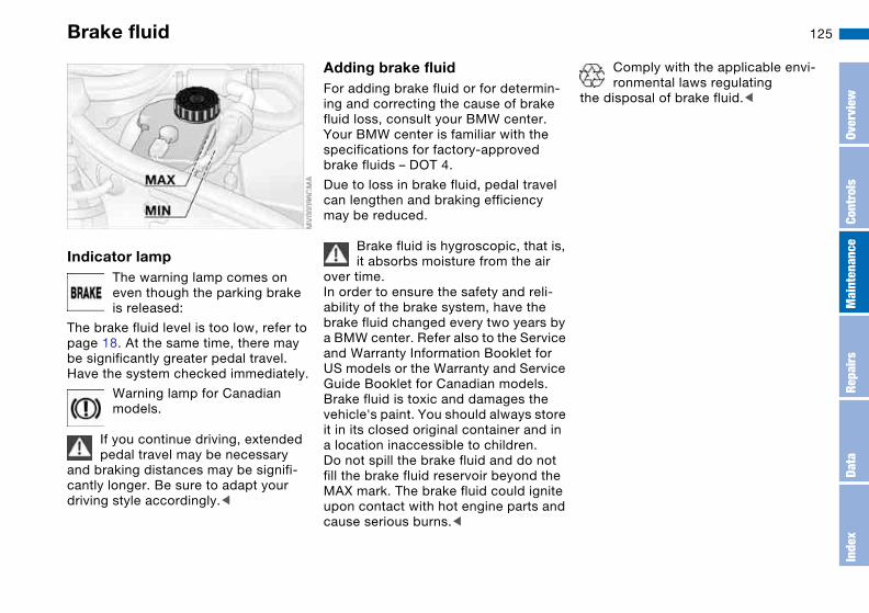
125Brake fluid
Indicator lampThe warning lamp comes on even though the parking brake is released:
The brake fluid level is too low, refer to page 18. At the same time, there may be significantly greater pedal travel. Have the system checked immediately.
Warning lamp for Canadian models.
If you continue driving, extended pedal travel may be necessary
and braking distances may be signifi-cantly longer. Be sure to adapt your driving style accordingly.<
Adding brake fluidFor adding brake fluid or for determin-ing and correcting the cause of brake fluid loss, consult your BMW center. Your BMW center is familiar with the specifications for factory-approved brake fluids – DOT 4.
Due to loss in brake fluid, pedal travel can lengthen and braking efficiency may be reduced.
Brake fluid is hygroscopic, that is, it absorbs moisture from the air
over time.In order to ensure the safety and reli-ability of the brake system, have the brake fluid changed every two years by a BMW center. Refer also to the Service and Warranty Information Booklet for US models or the Warranty and Service Guide Booklet for Canadian models. Brake fluid is toxic and damages the vehicle's paint. You should always store it in its closed original container and in a location inaccessible to children.Do not spill the brake fluid and do not fill the brake fluid reservoir beyond the MAX mark. The brake fluid could ignite upon contact with hot engine parts and cause serious burns.<
Comply with the applicable envi-ronmental laws regulating
the disposal of brake fluid.<
Over
view
Cont
rols
Mai
nten
ance
Repa
irs
Data
Inde
x
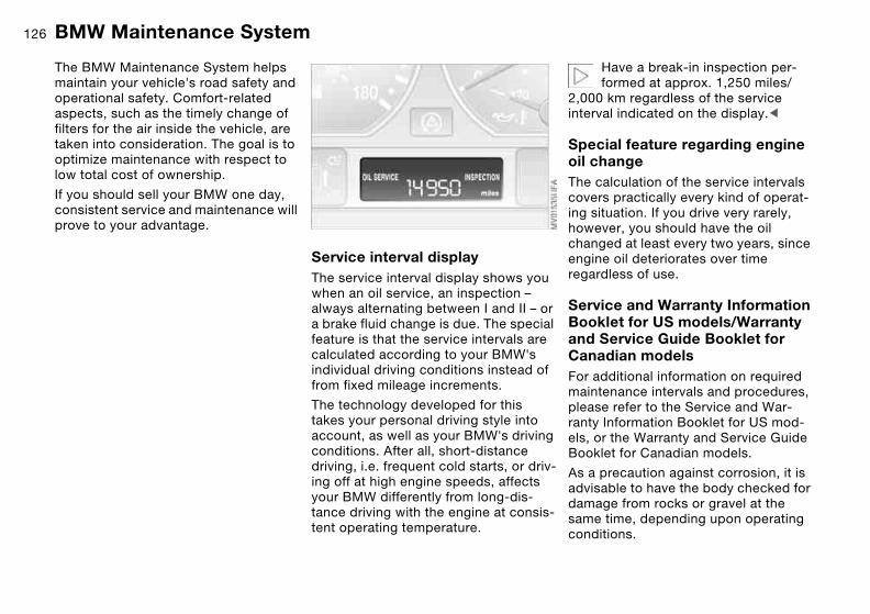
126
Maintenance
BMW Maintenance System
The BMW Maintenance System helps maintain your vehicle's road safety and operational safety. Comfort-related aspects, such as the timely change of filters for the air inside the vehicle, are taken into consideration. The goal is to optimize maintenance with respect to low total cost of ownership.
If you should sell your BMW one day, consistent service and maintenance will prove to your advantage.
Service interval displayThe service interval display shows you when an oil service, an inspection – always alternating between I and II – or a brake fluid change is due. The special feature is that the service intervals are calculated according to your BMW's individual driving conditions instead of from fixed mileage increments.
The technology developed for this takes your personal driving style into account, as well as your BMW's driving conditions. After all, short-distance driving, i.e. frequent cold starts, or driv-ing off at high engine speeds, affects your BMW differently from long-dis-tance driving with the engine at consis-tent operating temperature.
Have a break-in inspection per-formed at approx. 1,250 miles/
2,000 km regardless of the service interval indicated on the display.<
Special feature regarding engine oil changeThe calculation of the service intervals covers practically every kind of operat-ing situation. If you drive very rarely, however, you should have the oil changed at least every two years, since engine oil deteriorates over time regardless of use.
Service and Warranty Information Booklet for US models/Warranty and Service Guide Booklet for Canadian modelsFor additional information on required maintenance intervals and procedures, please refer to the Service and War-ranty Information Booklet for US mod-els, or the Warranty and Service Guide Booklet for Canadian models.
As a precaution against corrosion, it is advisable to have the body checked for damage from rocks or gravel at the same time, depending upon operating conditions.

127
Have your BMW center perform maintenance and repair.
Be sure that all maintenance work is recorded in the Service and Warranty Information Booklet for US models, or in the Warranty and Service Guide Booklet for Canadian models. These entries are your verification for the reg-ular maintenance of your vehicle and are required for the performance of warranty repairs.<
CareYou can find everything you need to know on this topic by consulting the separate Caring for your vehicle bro-chure.
BMW Maintenance System
Over
view
Cont
rols
Mai
nten
ance
Repa
irs
Data
Inde
x
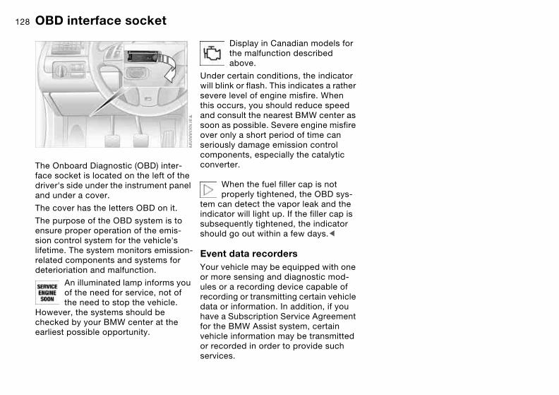
128
Laws and regulations
OBD interface socket
The Onboard Diagnostic (OBD) inter-face socket is located on the left of the driver's side under the instrument panel and under a cover.
The cover has the letters OBD on it.
The purpose of the OBD system is to ensure proper operation of the emis-sion control system for the vehicle's lifetime. The system monitors emission-related components and systems for deterioriation and malfunction.
An illuminated lamp informs you of the need for service, not of the need to stop the vehicle.
However, the systems should be checked by your BMW center at the earliest possible opportunity.
Display in Canadian models for the malfunction described above.
Under certain conditions, the indicator will blink or flash. This indicates a rather severe level of engine misfire. When this occurs, you should reduce speed and consult the nearest BMW center as soon as possible. Severe engine misfire over only a short period of time can seriously damage emission control components, especially the catalytic converter.
When the fuel filler cap is not properly tightened, the OBD sys-
tem can detect the vapor leak and the indicator will light up. If the filler cap is subsequently tightened, the indicator should go out within a few days.<
Event data recordersYour vehicle may be equipped with one or more sensing and diagnostic mod-ules or a recording device capable of recording or transmitting certain vehicle data or information. In addition, if you have a Subscription Service Agreement for the BMW Assist system, certain vehicle information may be transmitted or recorded in order to provide such services.

129
Over
view
Cont
rols
Mai
nten
ance
Repa
irs
Data
Inde
x

130

131
Overview
Controls and features
Operation, maintenance
Owner service procedures
Technical data
Index
Over
view
Cont
rols
Mai
nten
ance
Repa
irs
Data
Inde
x

132
Replacement procedures
Onboard tool kit
The onboard tool kit is located in the luggage compartment lid.
To open, loosen the wing nut.
For storing the towing eyelet refer to page 145.
Windshield wiper blades
1. Switch off the engine2. Fold the wiper arm completely out
from the windshield3. Position the wiper blade at an angle
and pull the release spring – see arrow
4. Fold the wiper blade down and unhook it toward the windshield
5. Pull the wiper blade past the wiper arm toward the top
6. Insert a new wiper blade and apply pressure until you hear it engage.

133Lamps and bulbs
The lamps and bulbs make essential contributions to the safety of your vehi-cle. Therefore, proceed carefully when handling bulbs. BMW recommends that you have such work performed by your BMW center if you are not familiar with the procedures.
Do not touch the glass portion of a new bulb with your bare hands
since even small amounts of impurities burn in to the surface and reduce the service life of the bulb. Use a clean cloth, paper napkin, or a similar mate-rial, or hold the bulb by its metallic base.<
A replacement bulb set is available from your BMW center.
Before working on the electrical system, switch off the electrical
accessory you are working on or dis-connect the cable from the negative terminal of the battery. Failure to observe this precaution could result in short circuits.To prevent injuries and damage when changing a bulb, be sure to comply with any instructions provided by the bulb manufacturer.<
Low beams and high beams>Low beams: H7 bulb, 55 watts.>High beams: H7 bulb, 55 watts.
The H7 bulb is pressurized. There-fore, wear safety glasses and pro-
tective gloves. Failure to comply with this precaution could lead to injury if the bulb is damaged.<
Please contact a BMW center in case of a malfunction.
When cleaning the headlamps, please follow the instructions in the Caring for your vehicle brochure.
Parking lamps5 watt bulb
Please contact a BMW center in case of a malfunction.
Xenon lamps*The service life of these bulbs is very long and the probability of a failure is very low, provided that they are not switched on and off an unusual number of times. If one of these bulbs should nevertheless fail, it is possible to con-tinue driving with great caution using the fog lamps, provided traffic laws in your area do not prohibit this.
Because of the extremely high voltages involved, any work on the
xenon lighting system, including bulb-changing, should be carried out by technically-qualified personnel only. Otherwise, there is a risk of fatal injury.<
Over
view
Cont
rols
Mai
nten
ance
Repa
irs
Data
Inde
x
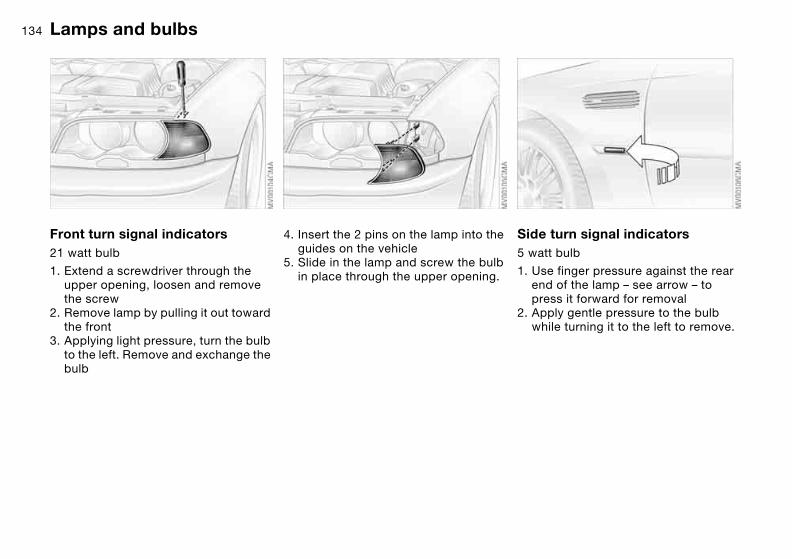
134
Front turn signal indicators21 watt bulb
1. Extend a screwdriver through the upper opening, loosen and remove the screw
2. Remove lamp by pulling it out toward the front
3. Applying light pressure, turn the bulb to the left. Remove and exchange the bulb
4. Insert the 2 pins on the lamp into the guides on the vehicle
5. Slide in the lamp and screw the bulb in place through the upper opening.
Side turn signal indicators5 watt bulb
1. Use finger pressure against the rear end of the lamp – see arrow – to press it forward for removal
2. Apply gentle pressure to the bulb while turning it to the left to remove.
Lamps and bulbs

135
Rear lamps1 Turn signal indicator
LEDs
2 Backup lamp 21 watt bulb
3 Tail lamp/brake lampLEDs
Please contact a BMW center in case of a defect with the LED
lamps.<
Bulbs in the luggage compartment lid1. Using a screwdriver, loosen the clip
2. Fold the trim panel down – see arrow 1. Disengage the bulb holder – see arrow 2 – and remove it
3. Applying light pressure, turn the bulb to the left. Remove and exchange the bulb
4. Press the bulb holder into position until you hear it engage
5. Reinstall the trim with the clip.
Lamps and bulbs
Over
view
Cont
rols
Mai
nten
ance
Repa
irs
Data
Inde
x

136
Center high-mount brake lampLED strip on the rear window.
Please contact a BMW center in case of a malfunction.
License plate lamps5 watt bulb
1. Place a screwdriver in the slot and press toward the left to release the lens
2. Replace the bulb.
Light-emitting diodesLight-emitting diodes (LEDs) installed behind translucent lenses serve as the light sources for many of the controls and displays in your vehicle. These light-emitting diodes are related to con-ventional lasers, and legislation defines them as light-emitting diodes, Class 1.
Do not remove the protective lens, and avoid staring directly at the
unfiltered beam for several hours, as inflammation of the retina could result.<
Lamps and bulbs
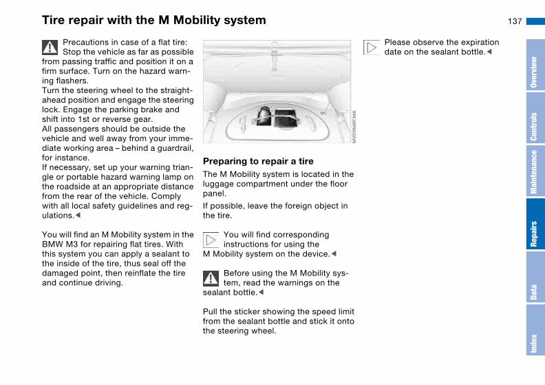
137Tire repair with the M Mobility system
Precautions in case of a flat tire:Stop the vehicle as far as possible
from passing traffic and position it on a firm surface. Turn on the hazard warn-ing flashers.Turn the steering wheel to the straight-ahead position and engage the steering lock. Engage the parking brake and shift into 1st or reverse gear.All passengers should be outside the vehicle and well away from your imme-diate working area – behind a guardrail, for instance.If necessary, set up your warning trian-gle or portable hazard warning lamp on the roadside at an appropriate distance from the rear of the vehicle. Comply with all local safety guidelines and reg-ulations.<
You will find an M Mobility system in the BMW M3 for repairing flat tires. With this system you can apply a sealant to the inside of the tire, thus seal off the damaged point, then reinflate the tire and continue driving.
Preparing to repair a tireThe M Mobility system is located in the luggage compartment under the floor panel.
If possible, leave the foreign object in the tire.
You will find corresponding instructions for using the
M Mobility system on the device.<
Before using the M Mobility sys-tem, read the warnings on the
sealant bottle.<
Pull the sticker showing the speed limit from the sealant bottle and stick it onto the steering wheel.
Please observe the expiration date on the sealant bottle.<
Over
view
Cont
rols
Mai
nten
ance
Repa
irs
Data
Inde
x
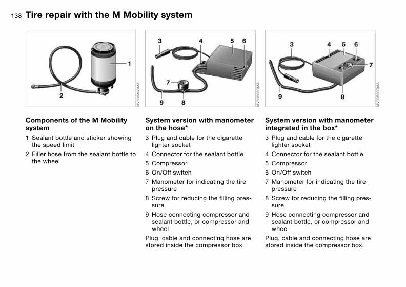
138
Components of the M Mobility system1 Sealant bottle and sticker showing
the speed limit
2 Filler hose from the sealant bottle to the wheel
System version with manometer on the hose*3 Plug and cable for the cigarette
lighter socket
4 Connector for the sealant bottle
5 Compressor
6 On/Off switch
7 Manometer for indicating the tire pressure
8 Screw for reducing the filling pres-sure
9 Hose connecting compressor and sealant bottle, or compressor and wheel
Plug, cable and connecting hose are stored inside the compressor box.
System version with manometer integrated in the box*3 Plug and cable for the cigarette
lighter socket
4 Connector for the sealant bottle
5 Compressor
6 On/Off switch
7 Manometer for indicating the tire pressure
8 Screw for reducing the filling pres-sure
9 Hose connecting compressor and sealant bottle, or compressor and wheel
Plug, cable and connecting hose are stored inside the compressor box.
Tire repair with the M Mobility system
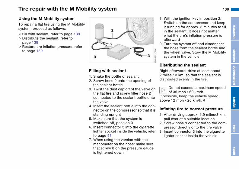
139
Using the M Mobility systemTo repair a flat tire using the M Mobility system, proceed as follows:
>Fill with sealant, refer to page 139>Distribute the sealant, refer to
page 139>Restore tire inflation pressure, refer
to page 139.
Filling with sealant1. Shake the bottle of sealant2. Screw hose 9 onto the opening of
the sealant bottle3. Twist the dust cap off of the valve on
the flat tire and screw filler hose 2 connected to the sealant bottle onto the valve
4. Insert the sealant bottle into the con-nector on the compressor so that it is standing upright
5. Make sure that the system is switched off, position 0
6. Insert connector 3 into the cigarette lighter socket inside the vehicle, refer to page 98
7. When using the version with the manometer on the hose: make sure that screw 8 on the pressure gauge is tightened down
8. With the ignition key in position 2:Switch on the compressor and keep it running for approx. 3 minutes to fill in the sealant. It does not matter what the tire's inflation pressure is afterward
9. Turn the system off and disconnect the hose from the sealant bottle and the wheel valve. Stow the M Mobility system in the vehicle.
Distributing the sealantRight afterward, drive at least about 2 miles / 3 km, so that the sealant is distributed evenly in the tire.
Do not exceed a maximum speed of 35 mph / 60 km/h.
If possible, keep the vehicle speed above 12 mph / 20 km/h.<
Inflating tire to correct pressure1. After driving approx. 1.9 miles/3 km,
pull over at a suitable location2. Screw hose 9 connected to the com-
pressor directly onto the tire valve3. Insert connector 3 into the cigarette
lighter socket inside the vehicle
Tire repair with the M Mobility system
Over
view
Cont
rols
Mai
nten
ance
Repa
irs
Data
Inde
x

140
4. Adjust the tire inflation pressure to 29 psi / 200 kilopascal. For this pur-pose, with the ignition key in position 2:> Increase the tire pressure: switch
on the compressor, position I. To check the current inflation pres-sure, turn off the device briefly
>Reduce the tire pressure: press button 8, or turn screw 8 on the manometer.
Do not run the compressor for longer than 10 minutes, otherwise
the unit may overheat and be dam-aged.<
If the tire fails to hold the pres-sure, drive the vehicle again, see
Distributing the sealant. Then repeat Steps 1 through 4 once.The use of the M Mobility system may be ineffective if the damaged area in the tire is larger than approx. 1/8 in / 4 mm. If the tire cannot be temporarily repaired with the M Mobility system, please consult the nearest BMW cen-ter, or a workshop that has appropri-ately trained personnel working in accordance with BMW specifications,<
The tire pressure must be at least 29 psi / 200 kilopascal. Otherwise,
do not continue driving.<
Driving onDo not exceed the maximum speed limit of 45 mph / 80 km/h;
otherwise, accidents may occur.<
Have the damaged tire replaced as soon as possible. Reinitialize
the Flat Tire Monitor, and refer to page 84 for further information.Have the sealant bottle of the M Mobil-ity system replaced.<
Battery
Battery posts, terminals, and related accessories contain lead
and lead compounds. Wash hands after handling.<
MaintenanceThe battery is completely maintenance-free. This means that the original bat-tery acid will normally last for the ser-vice life of the battery under moderate climate conditions. Your BMW center will be glad to advise you if you have any questions concerning the battery.
Please consult your BMW center whenever you have any questions
concerning the battery.<
Charging the batteryCharge the battery in the vehicle only when the engine is not running. Use the connections provided in the engine compartment. Terminals, refer to Jump-starting, page 143.
Tire repair with the M Mobility system

141
DisposalAfter changing the battery, have the old battery disposed of by
your BMW center or bring it to a recy-cling point. Maintain the battery in an upright position for transport and stor-age. Secure the battery against tilting in transit.<
Power lossAfter a temporary power loss, e.g. due to a discharged battery, some equip-ment will be limited in its use and will have to be reinitialized. Individual set-tings are also lost and must be reset:
>Seat and mirror memory The position settings must be stored again, refer to page 48
>Clock must be reset, refer to page 78
>RadioStations must be reset, refer to the Owner's Manual for Radio/Onboard Computer
>Navigation systemThe system will not be operable immediately, refer to the Owner's Manual for Radio/Onboard Com-puter.
Fuses
You will find the fuses and information on their respective allocation in the glove compartment behind a panel with two snap clips.
Do not attempt to repair a blown fuse or replace it with a fuse
having a different color or amperage rating. To do this could cause a fire in the vehicle resulting from a circuit over-load.<
Battery
Over
view
Cont
rols
Mai
nten
ance
Repa
irs
Data
Inde
x

142
Giving and receiving assistance
Receiving assistance
The BMW Group's Mobile Service offers you 24-hour assistance in the event of a breakdown, even on week-ends and holidays.
The telephone numbers of the Mobile Service control center in your country are listed in the Contact brochure.
If your vehicle has the necessary equip-ment, you can contact the Mobile Ser-vice or issue an emergency call using buttons in the interior rearview mirror.
When an emergency call is initiated, a telephone connection is established with the BMW Assist response center.
Fold down the cover.
1 Emergency call
2 Mobile Service
Requirements for initiating an emer-gency call or contacting Mobile Service:
> Ignition key in position 1 or higher>The car phone must be registered
with a mobile network>The emergency call system must be
operational.
Initiating an emergency call*Press button 1 for at least 2 seconds.
The indicator lamp above the buttons lights up. As soon as a telephone con-nection has been set up to the BMW Assist response center, the indicator lamp flashes.
If the situation permits you to do so, wait in the vehicle until the voice con-nection is established. You can then provide detailed information to the response center.
If your vehicle is equipped with an acti-vated BMW Assist and the current loca-tion of the vehicle can be determined, this location is transmitted to the BMW Assist response center.
If the navigation system has failed, the current location of the vehicle
is not transmitted.<
If the indicator lamp is flashing but you cannot hear the BMW Assist response center over the hands-free system, it is possible that e.g. the hands-free sys-tem is malfunctioning. The BMW Assist response center can still hear you, however.
If certain requirements are met, an emergency call is automatically initiated after a serious accident. The automatic emergency call will not be hindered by pressing the button.
For technical reasons, the emer-gency call function cannot be
guaranteed in certain unfavorable con-ditions.<

143
Mobile Service*To establish contact with the BMW Group's Mobile Service:
Press button 2 for at least 2 seconds.
The indicator lamp above the buttons lights up. As soon as a telephone con-nection has been set up with the Mobile Service, the indicator lamp flashes.
Depending on the country you are in, your vehicle's current location will also be transmitted if your vehicle is equipped with an activated BMW Assist function.
Jump-starting
When your battery is discharged, you can use two jumper cables to start your vehicle with power from the battery in a second vehicle. You can also use the same method to help start another vehicle. Use only jumper cables with fully insulated handles on the terminal clamps.
Do not touch high-voltage wiring and cables on a running engine.
Contact with components carrying high voltage can be harmful or fatal.Carefully observe the following instruc-tions to avoid personal injury and/or damage to one or both vehicles.<
Preparations1. Check whether the battery of the
support vehicle has 12 volts and approximately the same capacity – measured in Ah. This information is provided on the battery
2. Stop the engine of the support vehi-cle
3. Switch off all consumers in both vehicles.
Make absolutely certain that there is no contact between the body-
work of the two vehicles, otherwise there is a short circuit hazard.<
Connecting the jumper cablesBe sure to connect the jumper cables in the right order; other-
wise there is a risk of injury due to sparks being created near the battery.<
The jump-starting terminal located in your BMW's engine compartment serves as the positive battery terminal; refer also to the engine compartment overview on page 120. The cover of this auxiliary terminal is marked with a +.
1. Open the cover of the BMW jump-starting terminal. Do so by pulling the tab – see arrow 1
2. Connect one terminal clamp of the plus/+ jumper cable to the positive terminal of the battery or to a jump-starting terminal in the donor vehicle
Receiving assistance
Over
view
Cont
rols
Mai
nten
ance
Repa
irs
Data
Inde
x

144
3. Connect the second terminal clamp of the plus/+ jumper cable to the positive terminal of the battery or to a jump-starting terminal in the vehicle to be started
4. Your BMW is equipped with a special nut – see arrow 2 – to serve as the ground or negative terminal.Attach a terminal clamp of the minus/– jumper cable to the negative terminal of the support vehicle's bat-tery or to a suitable ground on its engine or bodywork
5. Attach the second terminal clamp of the minus/– jumper cable to the neg-ative terminal of the battery or to a suitable ground on the engine or bodywork of the vehicle to be started.
Starting the engine1. Start the engine of the support vehi-
cle and let it run for several minutes at a slightly elevated engine idle speed
2. Start the engine of the other vehicle as usual. If the first start attempt is not suc-cessful, wait a few minutes before another attempt in order to allow the discharged battery to recharge
3. Allow the engines to run for several minutes
4. Disconnect the jumper cables in reverse sequence.
Have the battery recharged at your BMW center as required.
Do not use spray starter fluids to start the engine.<
Jump-starting

145Towing and tow-starting the vehicle
Always observe all applicable towing laws and regulations.<
Using the towing eyeletThe screw-in towing eyelet is stored in the luggage compartment under the floor panel and must remain with the vehicle at all times. It can be attached at the front or rear of your BMW.
Observe the following instruc-tions in order to avoid damaging
the towing eyelet or the vehicle: use only the towing eyelet supplied with the vehicle, and screw it in firmly until it stops. Use the towing eyelet for towing on paved roads only. Avoid subjecting the towing eyelet to lateral loads, e.g. do not lift the vehicle using the towing eyelet.<
Access to the threaded socketPress out the cover in the front or rear bumper with a screwdriver at the top of the recess.
Being towedMake sure that the ignition key is in position 1, because the steering
lock could otherwise engage and the vehicle could no longer be steered.There is no power assist while the engine is off. Therefore, you will need to exert more force to brake and steer the vehicle.<
Turn on the hazard warning flashers, if required by national regulations. If the electrical system has failed, clearly identify the vehicle being towed, e.g. by placing a sign or a warning triangle in the rear window.
Vehicles with manual transmission: gearshift lever in idling position.
Vehicles with sequential M gearbox with Drivelogic: selector lever in posi-tion N.
Towing methodsIn some countries, it is not permitted to tow the vehicle with a tow bar or tow rope on public roads.
Familiarize yourself with the applicable towing regulations for the country in which you are driving.
With a tow barThe towing vehicle must not be lighter than the vehicle being
towed; otherwise, vehicle handling can no longer be controlled.<
The towing eyelets of both vehicles should be on the same side.
Over
view
Cont
rols
Mai
nten
ance
Repa
irs
Data
Inde
x

146
If the tow bar can only be used in a diagonal position, please note the fol-lowing:
>Clearance is restricted while you are driving around corners
>The inclination of the tow bar pro-duces lateral force.
Only attach the tow bar to the towing eyelets. Other parts of the
vehicles could otherwise be dam-aged.<
With a tow ropeWhen the towing vehicle is driving off, make sure that the tow rope is taut.
Use nylon ropes or straps for tow-ing because they prevent sudden
jerking movements. Attach the tow rope only to the towing eyelets. Other parts of the vehicles could otherwise be damaged.<
With a tow truckHave the BMW transported by a tow truck with a lift sling, or on a flatbed.
Never allow passengers to ride in a towed vehicle for any reason.<
Do not lift the vehicle by the tow-ing eyelet, nor by parts of the
body or chassis. Otherwise damage could result.<
Tow-startingOnly tow-start vehicles with catalytic converters if the engine is cold. It is better to jump-start the engine, refer to page 143.
1. Turn on hazard warning flashers; comply with national regulations
2. Turn the ignition key to position 23. Engage the 3rd gear4. Have the vehicle towed with the
clutch pedal completely depressed and then slowly release the clutch pedal. After the engine has started, immediately depress the clutch pedal again completely
5. Pull over at a suitable location, remove the tow bar or tow rope, and turn on the hazard warning flashers
6. Have the vehicle checked.
Vehicles with sequential M gearbox with Drivelogic:
>Have the vehicle towed with the selector lever in position N
>Move the selector lever into position S and pull it toward + within 2 sec-onds. The correct gear will automati-cally be selected and engaged
>After the engine has started, move the selector lever into position N again.
Towing and tow-starting the vehicle

147
Over
view
Cont
rols
Mai
nten
ance
Repa
irs
Data
Inde
x

148
149
Overview
Controls and features
Operation, maintenance
Owner service procedures
Technical data
Index
Over
view
Cont
rols
Mai
nten
ance
Repa
irs
Data
Inde
x

150 Engine data
DisplacementNumber of cylinders
cu in/cm3 198.1/3,2466
Max. power outputat engine speed
hprpm
3337,900
Maximum torqueat engine speed
lb ft/Nmrpm
262/3554,900
Compression ratio ε 11.5
StrokeBore
in/mmin/mm
3.58/913.43/87
Fuel mixture preparation Digital electronic engine-management system
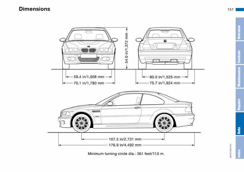
151Dimensions
Over
view
Cont
rols
Mai
nten
ance
Repa
irs
Data
Inde
x

152 Weights
Curb weight lbs/kg 3,415/1,549
Approved gross vehicle weight lbs/kg 4,453/2,020
Approved front axle load lbs/kg 2,138/970
Approved rear axle load lbs/kg 2,535/1,150
Approved roof load capacity lbs/kg 165/75
Luggage compartment capacity cu ft/l 14.5/410
Approved axle loads and approved gross vehicle weight must never be exceeded.

153Capacities
Notes
Fuel tankReserve
gal./litersgal./liters
approx. 16.6/approx. 63approx. 2.1/approx. 8
Fuel specification, refer to page 25
Windshield washer system/Headlamp cleaning system quarts/liters approx. 5.6/approx. 5.3
Specifications, refer to page 122
Engine with oil filter change quarts/liters approx. 5.8/approx. 5.5 Specifications, refer to page 123
Manual transmission quarts/liters approx. 1.9/approx. 1.8 Oil change during running-in check and during each inspection II
Differential quarts/liters approx. 1.2/approx. 1.1 Oil change during running-in check and during each inspection II
Over
view
Cont
rols
Mai
nten
ance
Repa
irs
Data
Inde
x

154

155
Overview
Controls and features
Operation, maintenance
Owner service procedures
Technical data
Index
Over
view
Cont
rols
Mai
nten
ance
Repa
irs
Data
Inde
x

Everything from A to Z
AABS Antilock Brake
System 111indicator lamp 19
Accessories, refer to For your own safety 6
Accident, refer to Emer-gency call 142
Activated-charcoal filter 94Adaptive brake lamp, refer
to Brake force display 86Adding brake fluid 125Additional sources of infor-
mation 4Air conditioning mode
automatic climate control 92
Air distributionautomatic climate control 92individual 92
Air outlets, refer to Ventila-tion 90
Air pressure, refer to Tire inflation pressure 112
Air recirculation, refer to Recirculated-air mode 93
Air supplyautomatic climate control 92
Air, drying, refer to Air con-ditioning mode 92
Airbags 52deactivating 52indicator lamp 18, 54safe seating position 42
Airing out, refer to Ventila-tion 90
AKI, refer to Fuel specifica-tions 25
Alarm system 37avoiding unintentional alarms 38
All-season tires, refer to Winter tires 116
Alternative oil types 123Antifreeze 124
coolant 124washer fluid 122
Antilock Brake System(ABS) 111indicator lamp 19
Anti-theft system 28Anti-theft warning system,
refer to Alarm system 37Approved axle loads, refer
to Weights 152Approved gross weight,
refer to Weights 152Armrest
front 96rear 97
Artificial leather, refer to the Caring for your vehicle brochure
Ashtrayfront 98rear 98
Assistant systems, refer to Dynamic Stability Control (DSC) 82
AUC Automatic recircu-lated-air control 93
AUTO program 92Automatic
cruise control 73headlamp control 87
Automatic air distribution, refer to AUTO program 92
Automatic air supply, refer to AUTO program 92
Automatic car wash, refer to the Caring for your vehicle brochure
Automatic climate control 90Automatic curb monitor 49Automatic dimming, interior
rearview mirror 50Automatic recirculated-air
control (AUC) 93Automatic windshield
washer, refer to Rain sen-sor 72
Average fuel consumption 80
Average speed 80Avoiding unintentional
alarms 38Axle loads, refer to
Weights 152
BBackrest
adjusting 43unlocking 46width adjustment 45
Backrest, refer to Seat adjustment 44
Backup lamps 65bulb replacement 135
Bandages, refer to First-aid kit 23
Bar, for towing 145Battery 140
charge 140disposal 141indicator lamp 18jump-starting 143remote control 28, 29
Battery charge current 18Belts, refer to Safety
belts 46Beverage holders 96, 97
Everything from A to Z 157
Blowerautomatic climate control 92
BMW Maintenance System 126
BMW sports seat 44Bore, refer to Engine
data 150Bottle holders, see Bever-
age holders 96, 97Brake fluid 125
indicator lamp 18, 125level 125
Brake force display 86Brake lamps
bulb replacement 135indicator lamp, defective lamp 77
Brake lamps, refer to Brake force display 86
Brake padsbrake fluid level 18, 125breaking in 108
Brake rotorsbreaking in 108
Brake systembrake pads, indicator lamp 19
Brake wear warningindicator lamp 19
BrakesABS 111brake fluid 125brake force display 86brake pads 110breaking in 108driving notes 109indicator/warning lamp 18, 19parking brake 64
Break-in procedures 108Bridging, refer to Jump-
starting 143Bulb replacement 133Bulb replacement, refer to
Lamps and bulbs 133Buttons in steering wheel 22
CCalifornia Proposition 65
warning 6Can holders, see Beverage
holders 96, 97Capacities 153Car battery 140Car care, refer to the Caring
for your vehicle brochureCar keys, refer to Keys 28Car phone hookup
microphone 97Car radio, refer to the
Owner's Manual for Radio
Car telephone, refer to the separate Owner's Manual
Car vacuum cleaner, con-necting 98
Car wash, refer to the Caring for your vehicle brochure
Caring for headlamp cov-ers, refer to the Caring for your vehicle brochure 133
Carpet care, refer to the Caring for your vehicle brochure
Cassette operation, refer to the Owner's Manual for Radio/Onboard Computer
CBC Cornering Brake Con-trol 111warning lamp 19
CD changer, refer to the Owner's Manual for Radio/Onboard Computer
CD operation, refer to the Owner's Manual for Radio/Onboard Computer
Center high-mount brake lampbulb replacement 136
Central locking system 28button 33passenger compartment 33
Charge indicator lamp 18
Check Control 77Check Gas Cap
indicator lamp 19Child seats, refer to Child-
restraint systems 55Child-restraint systems 55Cigarette lighter 98Cleaning chrome parts, refer
to the Caring for your vehi-cle brochure
Cleaning light alloy wheels, refer to the Caring for your vehicle brochure
Cleaning the vehicle, refer to the Caring for your vehicle brochure
Cleaning windshield 73Clock 78
12-/24-hour mode 78setting, refer also to the Owner's Manual for Radio/Onboard Computer
Closingfrom inside 33from outside 29
Clothes hooks 99Clutch
breaking in 108Cockpit 14Code, refer to the Owner's
Manual for Radio/Onboard Computer
Over
view
Cont
rols
Mai
nten
ance
Repa
irs
Data
Inde
x

Everything from A to Z
Coin box 96Cold start, refer to Starting
the engine 62Compact disc operation,
refer to the Owner's Man-ual for Radio/Onboard Computer
Compartments 96Compression ratio, refer to
Engine data 150Computer 79Condensation, refer to Air
conditioning mode 92Configuring settings, refer to
Vehicle Memory, Key Memory 59
Connecting a vacuum cleaner, refer to Power socket 98
Consumption, refer to Aver-age fuel consumption 80
Control elements, refer to Cockpit 14
Convenience operationfrom outside 32glass sunroof 30windows 30
Coolant 124indicator lamp 19, 76level 124temperature gauge 76
Coolant water, refer to Cool-ant 124
Cooling, refer to Tempera-ture 92
Copyright 4Cornering Brake Control
(CBC) 111warning lamp 19
Cruise control 73indicator lamp 20
Cup holders, see Beverage holders 96, 97
Curb weight, refer to Weights 152
Cylinders, refer to Engine data 150
DDashboard, refer to
Cockpit 14Data
capacities 153dimensions 151engine 150weights 152
Daytime driving lamps 87DBC Dynamic Brake
Control 111warning lamp 19
Deep water, refer to Driving through water 109
Defrost position, refer to Defrosting windows 92
Defrosting and demisting windowsautomatic climate control 92
Defrosting windows 92Defrosting windshield, refer
to Defrosting windows 92Demisting windows
automatic climate control 92
Differentialbreaking in 108
Digital clock 78Dimensions 151Dipstick, engine oil 122Displacement, refer to
Engine data 150Display lighting, refer to
Instrument lighting 88Displays, refer to Instrument
cluster 16Disposal
oil 123vehicle battery 141
Distance warning, refer to Park Distance Control (PDC) 81
Divided rear backrest 100Door key 28Door lock 32
Doorsemergency operation 32
Draft-free ventilation 93Drivelogic 69Driving light, refer to Parking
lamps/Low beams 87Driving notes 109Driving through water, deep
water 109Dry air, refer to Air condi-
tioning mode 92DSC Dynamic Stability Con-
trol 82indicator lamp 19, 82
Dynamic Brake Control (DBC) 111warning lamp 19
Dynamic Stability Control (DSC) 19, 82
Dynamic Stability Control DSCM Track mode 82
EEasy entry, refer to Entering
the rear 46Electric glass sunroof 40Electric power windows 39Electrical accessories, fail-
ure 141
Everything from A to Z 159
Electrical malfunctiondoor lock 32driver's door 32fuel filler door 24glass sunroof 41luggage compartment lid 34
Electronic Stability Program (ESP), refer to Dynamic Stability Control (DSC) 82
Emergency call 142Emergency operation
doors 32driver's door 32fuel filler door 24glass sunroof 41
Emergency releaseluggage compartment lid 34, 36
Enginebreaking in 108data 150electronics 19indicator lamp 19speed 75, 150starting 62switching off 64
Engine compartment 120Engine coolant 124
refilling 124
Engine oiladding 123additives, refer to Adding engine oil 123alternative oils 123capacity 153consumption 122indicator/warning lamp 19quality 123specified oils 123temperature gauge 75types 123
Engine oil level 19check 122indicator/warning lamp 18
Engine oil pressureindicator/warning lamp 18
Engine oil temperature 75Engine output, refer to
Engine data 150Engine speed 75, 150Entering the rear 46Equipment range, refer to
the Service and Warranty Information Booklet for US models / Warranty and Service Guide Booklet for Canadian models
ESP Electronic Stability Pro-gram, refer to Dynamic Stability Control (DSC) 82
Exterior mirrors 50
Eyeglasses compartment 97Eyelet, towing 145
FFalse alarm, refer to
Avoiding unintentional alarms 38
Fasten safety beltsindicator lamp 18
Fastening the safety belts 46Fault displays 77Filling the windshield washer
reservoir 153Filling with sealant
M Mobility system 139First aid, refer to First-aid
kit 23First-aid kit 23Flat tire 137
Flat Tire Monitor 83repairing 137
Flat Tire Monitor 83activating/deactivating 84indicator lamp 18, 19, 85
Floor panel, raising 36Fluid reservoir for washer
systems 122Fog lamps
indicator/warning lamp 20Folding rear backrest 100Follow me home lamps 87
Footbrake, refer to Braking safely 109
Front airbags 52Front center armrest 96Front fog lamps 89
indicator/warning lamp 20Fuel
display 76specifications 25volume 153
Fuel consumptiondisplay 80
Fuel display, refer to Fuel gauge 76
Fuel filler door 24release following an elec-trical malfunction 24
Fuel level indicator, refer to Fuel gauge 76
Fuel mixture preparation 150Fuel reserve indicator, refer
to Fuel gauge 76Fuel tank capacity 153Fuses 141
GGasoline consumption, refer
to Average fuel consump-tion 80
Gasoline, refer to Fuel spec-ifications 25
Gear indicator 67
Over
view
Cont
rols
Mai
nten
ance
Repa
irs
Data
Inde
x
Everything from A to Z
Gearboxmanual transmission 65
Gearbox malfunctionsequential M gearbox with Drivelogic 70
Gearbox, sequential 66Gearshift lever
manual transmission 65sequential M gearbox with Drivelogic 66
General driving notes 109Glass sunroof
closing following an elec-trical malfunction 41convenience operation30, 32remote control 29, 30
Glass sunroof, electric 40Glove compartment 95Gradient assistance 69Grills, refer to Ventilation 90Gross weight, refer to
Weights 152
HHandbrake, refer to Parking
brake 64Hands-free system 97Harman Kardon premium
sound system 95Hazard warning flashers 14Hazard warning triangle 23
Head airbags 52Head restraints 45Headlamp cleaning system
cleaning headlamps 73washer fluid 122, 153
Headlamp control 87Headlamp flasher 88
indicator lamp 21Headlamps
bulb replacement 133care, refer to the Caring for your vehicle brochure
Heated mirror 50Heated rear window
automatic climate control 93
Heated seats 49Heating
exterior mirrors 50rear window 93seats 49
Heating and ventilation 90Heavy loads, refer to Cargo
loading 103Height adjustment
seats 44steering wheel 51
Height, refer to Dimensions 151
High beams 71, 88bulb replacement 133headlamp flasher 88indicator lamp 21
Holder forbeverages 96, 97litter bag 97
Hood release 119Horn 14Hydraulic brake assistant,
refer to DBC 111Hydroplaning 109
IIce warning 79Ignition 61Ignition key 28
positions 61Ignition lock 61Imprint 4Indicator lamps 18
Indicator/warning lampairbags 18alarm system 38brakes 18, 19Check Gas Cap 19coolant 19, 76DSC 19Flat Tire Monitor18, 19, 85fog lamps 20Please fasten safety belts 18reserve 76Service Engine Soon 19
Individual air distribution 92Individual settings, refer to
Vehicle Memory, Key Memory 59
Inflation pressure monitor-ing, refer to Flat Tire Moni-tor 83
Inflation pressure, tires 112INSPECTION 77Instrument cluster 16Instrument lighting 88Instrument panel 14Interface socket for onboard
diagnostics (OBD) 128event data recorders 128
Interior lamps 89remote control 30
Everything from A to Z 161
Interior motion sensor 37, 38switching off 30, 38
Interior rearview mirrorautomatic dimming feature 50
Interior temperatureadjusting 92
Intermittent mode, wipers 72Interval display, service 77
JJump-starting 143
KKey Memory 59Keys 28
with remote control 28
LLamp defect 133Lamps and bulbs 133Lashing down loads, refer to
Cargo loading 102Lashing eyelets, refer to
Securing cargo 104Lashing fittings, refer to
Securing cargo 104LATCH child-restraint
mounting system 57Leather care, refer to the
Caring for your vehicle brochure
Leaving the vehicle 64LEDs light-emitting
diodes 136Length, refer to
Dimensions 151License plate lamp
bulb replacement 136Light switch 87Light-emitting diodes
(LEDs) 136Lighter 98LIGHTS ON warning 87Lights, refer to Parking
lamps/Low beams 87Litter bag holders 97Load, determining the maxi-
mum 102Load, refer to Cargo
loading 102Loading
vehicle 102Load-securing devices 104Lock buttons on doors, refer
to Locking 33Lock, steering wheel 61Locking
from inside 33from outside 29, 32
Locking and unlocking doorsfrom inside 33from outside 29, 32
Low beams 87automatic 87bulb replacement 133indicator lamp, defective lamp 77
Luggage compartmentcapacity 152emergency operation, refer to Manualoperation 34floor mat 37floor panel 36lid 34opening from outside 34opening, remote control 30opening/closing, refer to Luggage compartment lid 34remote control 30volume 152
Luggage compartment lid 34emergency operation 34emergency release 36indicator lamp 77opening from inside the vehicle 34, 35opening from outside 34remote control 30securing separately 34unlocking manually 34
Luggage compartment light-ing 34
Luggage rack, refer to Roof-mounted luggage rack 105
Lumbar support 44
MM Engine dynamics
control 85M Mobility system 137M Track mode 82
indicator lamp 20Maintenance 77, 126Maintenance system 126Making telephone calls,
refer to the telephone Owner's Manual
Malfunctiondoor lock 32fuel filler door 24
Malfunction displays 77Manual operation
door lock 32driver's door 32fuel filler door 24glass sunroof 41luggage compartment lid 34
Manual transmission 65Master keys
with remote control 28
Over
view
Cont
rols
Mai
nten
ance
Repa
irs
Data
Inde
x

Everything from A to Z
MC operation, refer to the Owner's Manual for Radio/Onboard Computer
MD operation, refer to the Owner's Manual for Radio/Onboard Computer
Mechanical seats 43Memory, refer to Seat and
mirror memory 48Memory, refer to Vehicle
Memory, Key Memory 59Microfilter
automatic climate control 94
Microphone 97Mini disc operation, refer to
the Owner's Manual for Radio/Onboard Computer
Mirrors 50automatic curb monitor 49heated 50memory, refer to Seat and mirror memory 48
Mobile Service 143Modifications, technical,
refer to For your own safety 6
Multifunction steering wheel 22
Multifunction switchturn signal indicator/head-lamp flasher 71washer/wiper system 72
NNavigation system, refer to
the Owner's Manual for Radio/Onboard Computer
Neck restraints, refer to Head restraints 45
Nets 96Nozzles, refer to
Ventilation 90Nylon rope, refer to Towing
and tow-starting the vehi-cle 145
OOBD interface socket 128Odometer 75Oil
additives, refer to Adding engine oil 123alternative oils 123capacity 153dipstick 122quality 123specified engine oils 123
Oil change interval, refer to Service interval display 126
Oil change intervals, refer to the Service and Warranty Information Booklet for US models / Warranty and Service Guide Booklet for Canadian models
Oil filter change 153Oil level
checking 122indicator lamp 18
Oil pressureindicator lamp 18
OIL SERVICE 77Oil types 123Old batteries, refer to Dis-
posal 141Onboard computer 79Onboard computer, refer to
the Owner's Manual for Onboard Computer
Onboard tool kit 132Opening and closing
from inside 33from outside 29via remote control 29via the door lock 32
Outlets, ventilation 90Outside temperature dis-
play 79changing unit of measure 79
PPaintwork care, refer to the
Caring for your vehicle brochure
Panic mode, trigger alarm 30
Park Distance Control (PDC) 81
Parking aid, refer to Park Distance Control (PDC) 81
Parking brake 64indicator lamp 18
Parking lamps 87bulb replacement 133
Parking lamps/Low beams 87
Parts and accessories, refer to Your individual vehicle 5
Passenger-side exterior mir-ror tilt function 49
PDC Park Distance Control 81
Plastic, refer to the Caring for your vehicle brochure
Pollen, refer to Microfil-ter/activated-charcoal fil-ter 94
Power output, refer to Engine data 150
Power seat 44Power socket 98

Everything from A to Z 163
Power socket, cigarette lighter 98
Pressure monitoring, tiresFlat Tire Monitor 83
Pressure, tires 112inflating with M Mobility system 139
Proposition 65 warning 6Puncture
M Mobility system 137
RRadio remote control key,
refer to Master key with remote control 28
Radio, refer to the Owner's Manual for Radio
Rain sensor 72Range 80Reading lamps
front 89rear 89
Rear armrest, refer to Rear center armrest 97
Rear backrest, folding 100Rear center 3-point safety
belt 100Rear lamps
bulb replacement 135indicator lamp, defective lamp 77
Rear window heatingautomatic climate control 93
Rear-entry assist 46Rearview mirror 50Receiving assistance 142Recirculated-air mode
automatic climate control 93
Recirculating the air, refer to Recirculated-air mode 93
Reclining seat, refer to Seat adjustment 44
Refueling 24fuel filler door 24
Releasinghood 119
Remaining distance to ser-vice 77
Remaining distance, refer to Range 80
Remote control 29luggage compartment lid 30malfunction 30
Replacing lamps, refer to Lamps and bulbs 133
Reporting safety defects 7Restraint systems
for children 55Restraint systems, refer to
Safety belts 46
Reverse gearmanual transmission 65
Roof load capacity 152Roof-mounted luggage
rack 105Rope, refer to Towing
and tow-starting the vehi-cle 145
SSafe seating position 42
airbags 42safety belt 42
Safety beltsafe seating position 42
Safety belt height adjust-ment 47
Safety belts 46height adjustment 47warning lamp 18
Safety featureglass sunroof 40power windows 39
Safety systems, refer toAntilock Brake System 111Dynamic Stability Control (DSC) 82
Screwdriver, refer to Onboard tool kit 132
Seat adjustmentbackrest width adjust-ment 45BMW sports seat 44height 43lumbar support 44manual 43power 44
Seat belt tensioner, refer to Safety belts 46
Seat heating 49Seat memory, refer to Seat
and mirror memory 48Seat positions, storing 48Seats 43Securing cargo 104Securing child-restraint sys-
tem 57Securing the vehicle
from inside 33from outside 29, 32
Selector leversequential M gearbox with Drivelogic 66
Selector lever positionssequential M gearbox with Drivelogic 66
Sequential M gearbox with Drivelogic 66indicator lamp 19, 70tow-starting 146
Over
view
Cont
rols
Mai
nten
ance
Repa
irs
Data
Inde
x
Everything from A to Z
Service and Warranty Infor-mation Booklet 126
Service Engine Soonwarning lamp 19
Service interval display77, 126
Shift lights 70Shift paddles 67Side airbags 52Side turn signal indicators
bulb replacement 134Size 151Ski bag 101Sliding/tilt sunroof, refer to
Electric glass sunroof 40SMG Drivelogic 66Smokers' package, refer to
Ashtray 98Snow chains 118SOS, refer to Emergency
call 142Spare key 28, 29Special oils 123Special oils, refer to Speci-
fied engine oils 123Specified engine oils 123Speed gauge, refer to
Speedometer 16Speedometer 16Sport mode 85Sports seat 44
Stability control, refer to Dynamic Stability Control (DSC) 82
Stability control, refer to M Track mode 82
Standing lamps 88bulb replacement 133
Starting difficultiesjump-starting 143temperature 62
Starting the engine 62Starting, refer to Starting the
engine 62Starting-off assistance
DSC 82gradient assistance 69
Status of the Owner's Man-ual 5
Steering wheel lock 61Steering wheel, adjusting 51Storage compartments 96Storage nets 96Storing seat positions,
refer to Seat and mirror memory 48
Storing tires 117Stroke, refer to Engine
data 150Sun blind 94Sun blind, refer to Roller sun
blind 94
Surface ice, refer to Ice warning 79
Switches, refer to Cockpit 14
Switching offengine 64
Symbols 4
TTachometer 75Tail lamps
bulb replacement 135Tail lamps, refer to Rear
lamps 135Tank capacity, refer to Fuel
tank capacity 153Tank indicator, refer to Fuel
gauge 76Technical data 150Technical modifications 6Technical modifications,
refer to For your own safety 6
Telephone hookupmicrophone 97
Telephone, refer to the sep-arate Owner's Manual
Television, refer to the Owner's Manual for Onboard Computer
Temperatureautomatic climate control 92
Temperature adjustment 92Temperature display
engine coolant 76outside temperature 79setting units 79
Temperature layering 93Tempomat, refer to Cruise
control 73Thigh support area, adjust-
ing 44Third brake lamp, refer to
Center high-mount brake lamp 136
Threaded socket for towing eyelet 145
Three-point safety belt 46Through-loading system 100Tilt alarm sensor 30, 38
remote control 30switching off 30, 38
Tilting passenger-side exte-rior mirror 49
Time 78Tire inflation pressure 112Tire pressure monitoring,
refer to Flat Tire Monitor 83
Everything from A to Z 165
Tiresage 114breaking in 108condition 115damage 115flat 137inflation pressure 112storing 117tread 115, 116tread wear indicators, refer to Tire tread 116winter tires 116
Tools 132Torque
engine 150Tow bar 145Tow rope 145Towing 145Towing eyelet 145Towing the vehicle 145Tow-starting 145Track mode, refer to M
Track mode 82Track width, refer to Dimen-
sions 151Transmission
breaking in 108Transport securing devices,
refer to Securing cargo 104
Transporting children safely 55
Trap protectionglass sunroof 40power windows 39
Tread depth, refer to Tire tread 116
Tread wear indicators in the tires, refer to Tiretread 116
Tread wear, tires 116Trip distance recorder, refer
to Trip odometer 75Trip meter, refer to Trip
odometer 75Trip odometer 75Trunk lid, refer to Luggage
compartment lid 34Trunk lighting, refer to Lug-
gage compartment light-ing 34
Turn signal indicator 71bulb replacement 134indicator lamp 20
Turn signal indicator, sidebulb replacement 134
Turning circle, refer to Dimensions 151
TV function, refer to the Owner's Manual for Onboard Computer
UUnderbody protection, refer
to the Caring for your vehi-cle brochure
Unitsaverage fuel consumption 80temperature 79
Unlockingfrom inside 33from outside 29, 32
Upshift indicator, refer to Shift Lights 70
VVehicle
battery 140break-in procedures 108dimensions 151leaving the vehicle 64loading 102starting 62washing, refer to the Car-ing for your vehicle bro-chure 72weight 152
Vehicle Memory 59Vehicle weight 152Ventilation 90
draft-free 93Viscosity 123
Voice command system 22microphone 97
Voice control, refer to sepa-rate Owner's Manual
Volumeluggage compartment 152
WWarning and indicator
lamps 18Warning lamp 'Please fas-
ten safety belts' 18Warning messages 77Warranty and Service Guide
Booklet 126Warranty, refer also to sepa-
rate booklet 7Washer fluid
adding 122, 153Washer fluid reservoir 122
volume 122Washer jets, refer to Wind-
shield washer jets 73Washer/wiper system 72, 73
washer fluid 122Waste tray, refer to
Ashtray 98Weights 152Wheelbase, refer to Dimen-
sions 151Wheels and tires 112Wheelslip control DSC 82
Over
view
Cont
rols
Mai
nten
ance
Repa
irs
Data
Inde
x

Everything from A to Z
Width, refer to Dimensions 151
Window condensationremoving 92
Windowsconvenience operation30, 32power 39remote control 29, 30
Windshield washer nozzles 73
Windshield washer reservoirvolume, see Capacities 153
Windshield wiper blades, replacing 132
Windshield wipers, refer to Washer/wiper system 72
Winter tires 116storing 117
Wiper blades, replacing 132Work in the engine compart-
ment 119
XXenon lamps
bulb replacement 133

167
Over
view
Cont
rols
Mai
nten
ance
Repa
irs
Data
Inde
x

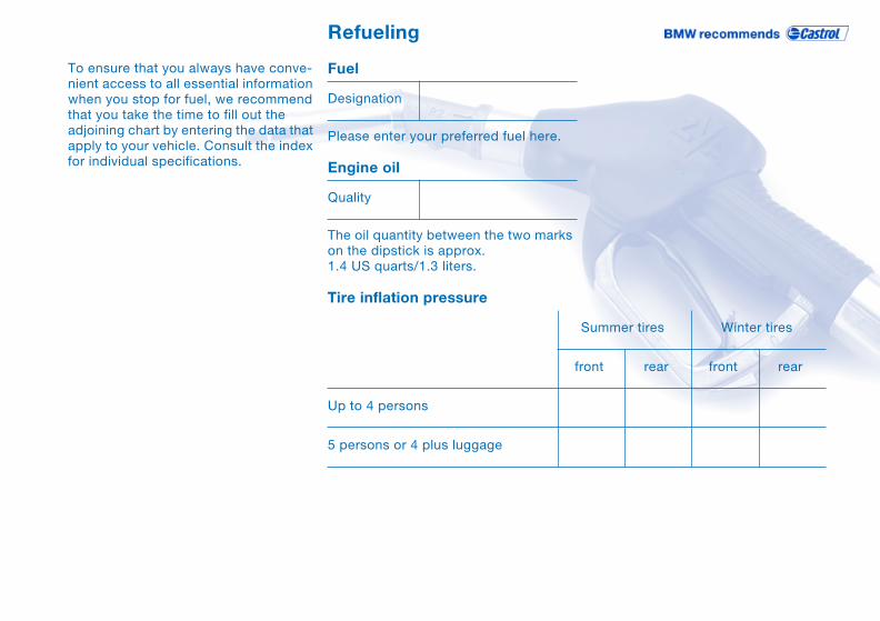
Refueling
To ensure that you always have conve-nient access to all essential information when you stop for fuel, we recommend that you take the time to fill out the adjoining chart by entering the data that apply to your vehicle. Consult the index for individual specifications.
Fuel
Please enter your preferred fuel here.
Engine oil
The oil quantity between the two marks on the dipstick is approx. 1.4 US quarts/1.3 liters.
Tire inflation pressure
Designation
Quality
Summer tires Winter tires
front rear front rear
Up to 4 persons
5 persons or 4 plus luggage
More about BMW
bmwusa.com The Ultimate
Driving Machine
01
41
0 1
58
51
2 u
e