owner’s guide xpower inverter 1500 - xantrex xpower inverter 1500 owner’s guide about this guide...
TRANSCRIPT
TM
TM
XPower™ Inverter 1500Owner’s Guide

975-0558-01-01 i
About XantrexXantrex Technology Inc. (www.xantrex.com), a subsidiary of Schneider Electric, is a world leader in the development, manufacturing and marketing of advanced power electronic products and systems for the renewable and mobile power markets. The company's products convert and control raw electrical power from any central, distributed, renewable, or backup power source into high-quality power required by electronic equipment and the electricity grid. Xantrex is headquartered in Vancouver, Canada, with facilities in the United States, Germany, Spain, India, and a joint venture in China.
TrademarksXantrex, XPower, and Smart Choice for Power are trademarks of Schneider Electric International Services sprl, registered in the U.S. and other countries. Other trademarks, registered trademarks, and product names are the property of their respective owners and are used herein for identification purposes only.
Notice of CopyrightXPower Inverter 1500 Owner’s Guide © February 2010 Xantrex Technology Inc. All rights reserved. No part of this document may be reproduced in any form or disclosed to third parties without the express written consent of: Xantrex Technology Inc., 161-G South Vasco Road, Livermore, California, USA 94551. Xantrex Technology Inc. reserves the right to revise this document and to periodically make changes to the content hereof without obligation or organization of such revisions or changes unless required to do so by prior arrangement.
Exclusion for DocumentationUNLESS SPECIFICALLY AGREED TO IN WRITING, XANTREX TECHNOLOGY INC. (“XANTREX”)(A) MAKES NO WARRANTY AS TO THE ACCURACY, SUFFICIENCY OR SUITABILITY OF ANY TECHNICAL OR OTHER INFORMATION PROVIDED IN ITS MANUALS OR OTHER DOCUMENTATION;(B) ASSUMES NO RESPONSIBILITY OR LIABILITY FOR LOSSES, DAMAGES, COSTS OR EXPENSES, WHETHER SPECIAL, DIRECT, INDIRECT, CONSEQUENTIAL OR INCIDENTAL, WHICH MIGHT ARISE OUT OF THE USE OF SUCH INFORMATION. THE USE OF ANY SUCH INFORMATION WILL BE ENTIRELY AT THE USER’S RISK; AND(C) REMINDS YOU THAT IF THIS MANUAL IS IN ANY LANGUAGE OTHER THAN ENGLISH, ALTHOUGH STEPS HAVE BEEN TAKEN TO MAINTAIN THE ACCURACY OF THE TRANSLATION, THE ACCURACY CANNOT BE GUARANTEED. APPROVED XANTREX CONTENT IS CONTAINED WITH THE ENGLISH LANGUAGE VERSION WHICH IS POSTED AT WWW.XANTREX.COM.
Date and RevisionFebruary 2010 Rev B
Document Part Number975-0558-01-01
Product Number813-1500-UL
Contact InformationTelephone: 1 800 670 0707 (toll free North America)
1 408 987 6030 (direct)Fax: 1 800 994 7828 (toll free North America)Email: [email protected]: www.xantrex.com
ii XPower Inverter 1500 Owner’s Guide
About This Guide
PurposeThe purpose of this Owner’s Guide is to provide explanations and procedures for installing, operating, troubleshooting, and maintaining the XPower Inverter 1500 .
ScopeThe Guide provides safety and operating guidelines as well as information on installing and configuring the inverter. It also provides information about troubleshooting the unit. It does not provide details about particular brands of batteries. You need to consult individual battery manufacturers for this information.
AudienceThe Guide is intended for users and operators of the XPower Inverter 1500 .
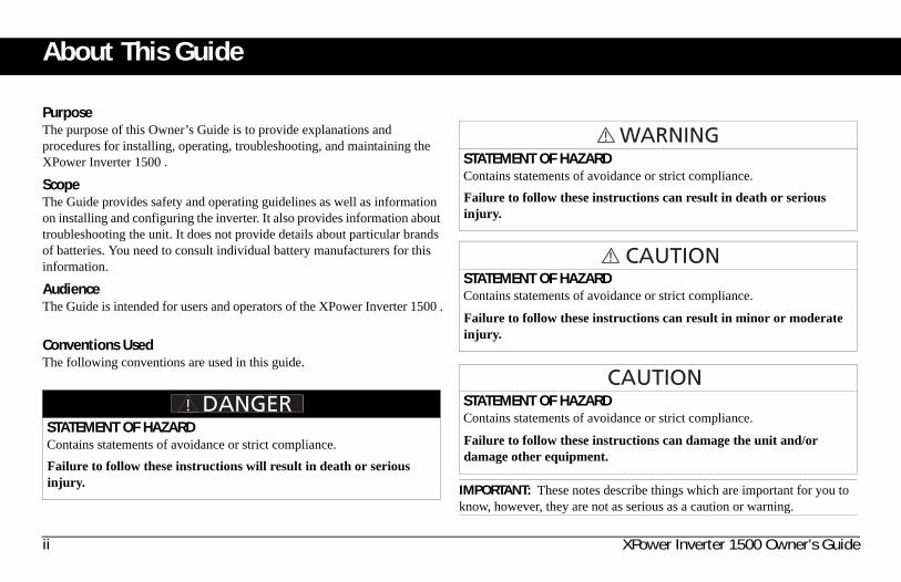
Conventions UsedThe following conventions are used in this guide.
STATEMENT OF HAZARDContains statements of avoidance or strict compliance.Failure to follow these instructions will result in death or serious injury.
STATEMENT OF HAZARDContains statements of avoidance or strict compliance.
Failure to follow these instructions can result in death or serious injury.
STATEMENT OF HAZARDContains statements of avoidance or strict compliance.
Failure to follow these instructions can result in minor or moderate injury.
STATEMENT OF HAZARDContains statements of avoidance or strict compliance.
Failure to follow these instructions can damage the unit and/or damage other equipment.
IMPORTANT: These notes describe things which are important for you to know, however, they are not as serious as a caution or warning.

975-0558-01-01 iii
Related InformationYou can find more information about Xantrex Technology Inc. as well as its products and services at www.xantrex.com.

iv XPower Inverter 1500 Owner’s Guide
Important Safety Instructions
IMPORTANT: READ AND SAVE THIS OWNER’S GUIDE FOR FUTURE REFERENCE.
This chapter contains important safety and installation instructions for the XPower Inverter 1500 . Each time, before using the XPower Inverter 1500 , READ ALL instructions and cautionary markings on or provided with the inverter and all appropriate sections of this guide.NOTE: The XPower Inverter 1500 contains no user-serviceable parts. See “Warranty and Return Information” on page 20 for guidance.
NOTE: Turning off the inverter using the on/off switch on the front panel will not reduce an electrical shock hazard.
ELECTRICAL SHOCK HAZARD• Do not expose the inverter to rain, snow, spray, or bilge water. This
inverter is designed for indoor use only.• Do not operate the inverter if it has received a sharp blow, been
dropped, has cracks or openings in the enclosure including if the fuse cover has been lost, damaged, or will not close, or otherwise damaged in any other way.
• Do not disassemble the inverter. Internal capacitors remain charged after all power is disconnected.
• Disconnect both AC and DC power from the inverter before attempting any maintenance or cleaning or working on any circuits connected to the inverter. See note below.
• Do not operate the inverter with damaged or substandard wiring. Make sure that all wiring is in good condition and is not undersized.
Failure to follow these instructions will result in death or serious injury.
975-0558-01-01 v
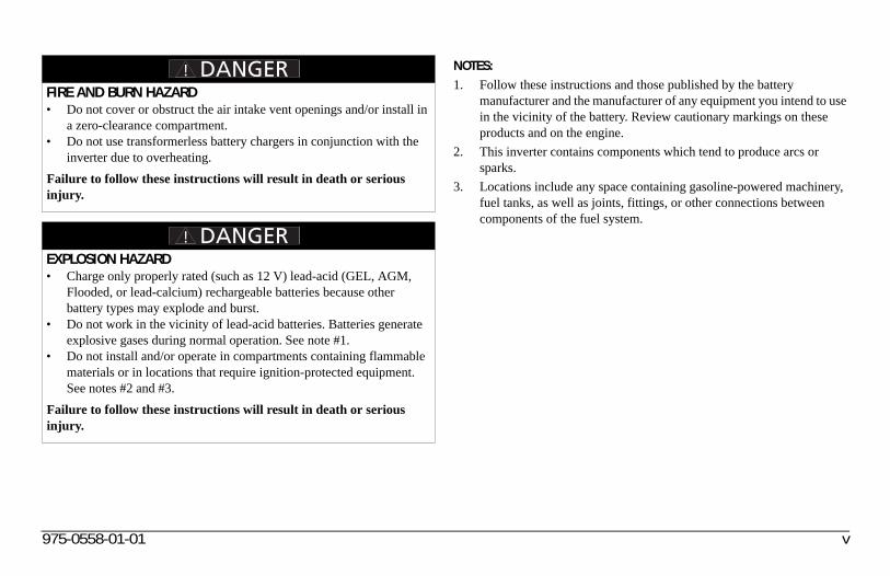
NOTES:1. Follow these instructions and those published by the battery
manufacturer and the manufacturer of any equipment you intend to use in the vicinity of the battery. Review cautionary markings on these products and on the engine.
2. This inverter contains components which tend to produce arcs or sparks.
3. Locations include any space containing gasoline-powered machinery, fuel tanks, as well as joints, fittings, or other connections between components of the fuel system.
FIRE AND BURN HAZARD• Do not cover or obstruct the air intake vent openings and/or install in
a zero-clearance compartment.• Do not use transformerless battery chargers in conjunction with the
inverter due to overheating.Failure to follow these instructions will result in death or serious injury.
EXPLOSION HAZARD• Charge only properly rated (such as 12 V) lead-acid (GEL, AGM,
Flooded, or lead-calcium) rechargeable batteries because other battery types may explode and burst.
• Do not work in the vicinity of lead-acid batteries. Batteries generate explosive gases during normal operation. See note #1.
• Do not install and/or operate in compartments containing flammable materials or in locations that require ignition-protected equipment. See notes #2 and #3.
Failure to follow these instructions will result in death or serious injury.
vi XPower Inverter 1500 Owner’s Guide
Precautions When Working With Batteries
NOTES:1. Locate the XPower Inverter 1500 unit away from batteries in a well
ventilated compartment.2. Always have someone within range of your voice or close enough to
come to your aid when you work near a lead-acid battery.3. Always have plenty of fresh water and soap nearby in case battery acid
contacts skin, clothing, or eyes.4. If battery acid contacts skin or clothing, wash immediately with soap
and water. If acid enters your eye, immediately flood it with running cold water for at least twenty minutes and get medical attention immediately.
5. Use extra caution to reduce the risk or dropping a metal tool on the battery. It could spark or short circuit the battery or other electrical parts and could cause an explosion.
6. Batteries can produce a short circuit current high enough to weld a ring or metal bracelet or the like to the battery terminal, causing a severe burn.
7. When removing a battery, always remove the negative terminal from the battery first for systems with grounded negative. If it is grounded positive, remove the positive terminal first. Make sure all loads connected to the battery and all accessories are off so you don’t cause an arc.
BURN FROM HIGH SHORT-CIRCUIT CURRENT, FIRE AND EXPLO-SION FROM VENTED GASES HAZARDS• Always wear proper, non-absorbent gloves, complete eye protection,
and clothing protection. Avoid touching your eyes and wiping your forehead while working near batteries. See note #4.
• Remove all personal metal items, like rings, bracelets, and watches when working with batteries. See notes #5 and #6 below.
• Never smoke or allow a spark or flame near the engine or batteries.• Never charge a frozen battery.Failure to follow these instructions can result in death or serious injury.
975-0558-01-01 vii
Precautions When Placing the Inverter RegulatoryThe XPower Inverter 1500 is certified to UL458 standard. For more information see “Regulatory Approvals” on page 19.The XPower Inverter 1500 is intended to be used for residential or commercial applications. It is not intended for other applications as it may not comply with the additional safety code requirements needed for those other applications. See “Limitations On Use” below.
RISK OF DAMAGE TO THE inverter• Never allow battery acid to drip on the inverter when reading gravity,
or filling battery.• Never place the XPower Inverter 1500 unit directly above batteries;
gases from a battery will corrode and damage the inverter.• Do not place a battery on top of the inverter.
Failure to follow these instructions can damage the unit and/or damage other equipment.
LIMITATIONS ON USE• Do not use in connection with life support systems or other medical
equipment or devices.• Do not use in ambulances or other life-saving emergency vehicles.Failure to follow these instructions can result in death or serious injury.

Important Safety Instructions . . . . . . . . . . . . . . . . . . . . . . . . . . . . . . . . . . . . . . . . . . . . . . . . . . . . . . . . . . . . . . . . . . . . . . . . . . . . . . . . . . . . . iv
Introduction . . . . . . . . . . . . . . . . . . . . . . . . . . . . . . . . . . . . . . . . . . . . . . . . . . . . . . . . . . . . . . . . . . . . . . . . . . . . . . . . . . . . . . . . . . . . . . . . . . . .1Quality Power . . . . . . . . . . . . . . . . . . . . . . . . . . . . . . . . . . . . . . . . . . . . . . . . . . . . . . . . . . . . . . . . . . . . . . . . . . . . . . . . . . . . . . . . . .1Ease of Use . . . . . . . . . . . . . . . . . . . . . . . . . . . . . . . . . . . . . . . . . . . . . . . . . . . . . . . . . . . . . . . . . . . . . . . . . . . . . . . . . . . . . . . . . . . .1Comprehensive Protection . . . . . . . . . . . . . . . . . . . . . . . . . . . . . . . . . . . . . . . . . . . . . . . . . . . . . . . . . . . . . . . . . . . . . . . . . . . . . . . . .1inverter Materials List . . . . . . . . . . . . . . . . . . . . . . . . . . . . . . . . . . . . . . . . . . . . . . . . . . . . . . . . . . . . . . . . . . . . . . . . . . . . . . . . . . . .2
Inverter Features . . . . . . . . . . . . . . . . . . . . . . . . . . . . . . . . . . . . . . . . . . . . . . . . . . . . . . . . . . . . . . . . . . . . . . . . . . . . . . . . . . . . . . . . . . . . . . . .3AC Panel . . . . . . . . . . . . . . . . . . . . . . . . . . . . . . . . . . . . . . . . . . . . . . . . . . . . . . . . . . . . . . . . . . . . . . . . . . . . . . . . . . . . . . . . . . . . . .3DC Panel . . . . . . . . . . . . . . . . . . . . . . . . . . . . . . . . . . . . . . . . . . . . . . . . . . . . . . . . . . . . . . . . . . . . . . . . . . . . . . . . . . . . . . . . . . . . . .4
Inverter Installation . . . . . . . . . . . . . . . . . . . . . . . . . . . . . . . . . . . . . . . . . . . . . . . . . . . . . . . . . . . . . . . . . . . . . . . . . . . . . . . . . . . . . . . . . . . . . .5Installation Code . . . . . . . . . . . . . . . . . . . . . . . . . . . . . . . . . . . . . . . . . . . . . . . . . . . . . . . . . . . . . . . . . . . . . . . . . . . . . . . . . . . . . . . .5Prepare for Installation . . . . . . . . . . . . . . . . . . . . . . . . . . . . . . . . . . . . . . . . . . . . . . . . . . . . . . . . . . . . . . . . . . . . . . . . . . . . . . . . . . . .5
Typical Power System Design . . . . . . . . . . . . . . . . . . . . . . . . . . . . . . . . . . . . . . . . . . . . . . . . . . . . . . . . . . . . . . . . . . . . . . . . . .6Battery Requirements . . . . . . . . . . . . . . . . . . . . . . . . . . . . . . . . . . . . . . . . . . . . . . . . . . . . . . . . . . . . . . . . . . . . . . . . . . . . . . . . .6Charging System . . . . . . . . . . . . . . . . . . . . . . . . . . . . . . . . . . . . . . . . . . . . . . . . . . . . . . . . . . . . . . . . . . . . . . . . . . . . . . . . . . . . .6Location . . . . . . . . . . . . . . . . . . . . . . . . . . . . . . . . . . . . . . . . . . . . . . . . . . . . . . . . . . . . . . . . . . . . . . . . . . . . . . . . . . . . . . . . . . .7Cables for DC Input and Ground . . . . . . . . . . . . . . . . . . . . . . . . . . . . . . . . . . . . . . . . . . . . . . . . . . . . . . . . . . . . . . . . . . . . . . . .7Fuses (or Circuit Breakers) . . . . . . . . . . . . . . . . . . . . . . . . . . . . . . . . . . . . . . . . . . . . . . . . . . . . . . . . . . . . . . . . . . . . . . . . . . . . .7
Install the Inverter . . . . . . . . . . . . . . . . . . . . . . . . . . . . . . . . . . . . . . . . . . . . . . . . . . . . . . . . . . . . . . . . . . . . . . . . . . . . . . . . . . . . . . .8Overview of Installation Steps . . . . . . . . . . . . . . . . . . . . . . . . . . . . . . . . . . . . . . . . . . . . . . . . . . . . . . . . . . . . . . . . . . . . . . . . . . . . . .8
Mount the Inverter . . . . . . . . . . . . . . . . . . . . . . . . . . . . . . . . . . . . . . . . . . . . . . . . . . . . . . . . . . . . . . . . . . . . . . . . . . . . . . . . . . .8Connect the Chassis Ground . . . . . . . . . . . . . . . . . . . . . . . . . . . . . . . . . . . . . . . . . . . . . . . . . . . . . . . . . . . . . . . . . . . . . . . . . . . .8Connect the DC Cables . . . . . . . . . . . . . . . . . . . . . . . . . . . . . . . . . . . . . . . . . . . . . . . . . . . . . . . . . . . . . . . . . . . . . . . . . . . . . . . .9
Contents

Inverter Operation . . . . . . . . . . . . . . . . . . . . . . . . . . . . . . . . . . . . . . . . . . . . . . . . . . . . . . . . . . . . . . . . . . . . . . . . . . . . . . . . . . . . . . . . . . . . . .11Turning the Inverter On and Off . . . . . . . . . . . . . . . . . . . . . . . . . . . . . . . . . . . . . . . . . . . . . . . . . . . . . . . . . . . . . . . . . . . . . . . . . . .11Testing the GFCI . . . . . . . . . . . . . . . . . . . . . . . . . . . . . . . . . . . . . . . . . . . . . . . . . . . . . . . . . . . . . . . . . . . . . . . . . . . . . . . . . . . . . . .12Operating Several Loads at Once . . . . . . . . . . . . . . . . . . . . . . . . . . . . . . . . . . . . . . . . . . . . . . . . . . . . . . . . . . . . . . . . . . . . . . . . . .12Operating Limits . . . . . . . . . . . . . . . . . . . . . . . . . . . . . . . . . . . . . . . . . . . . . . . . . . . . . . . . . . . . . . . . . . . . . . . . . . . . . . . . . . . . . . .12Inverter Loads . . . . . . . . . . . . . . . . . . . . . . . . . . . . . . . . . . . . . . . . . . . . . . . . . . . . . . . . . . . . . . . . . . . . . . . . . . . . . . . . . . . . . . . . .13
High Surge Loads . . . . . . . . . . . . . . . . . . . . . . . . . . . . . . . . . . . . . . . . . . . . . . . . . . . . . . . . . . . . . . . . . . . . . . . . . . . . . . . . . . .13Trouble Loads . . . . . . . . . . . . . . . . . . . . . . . . . . . . . . . . . . . . . . . . . . . . . . . . . . . . . . . . . . . . . . . . . . . . . . . . . . . . . . . . . . . . . .13
Connecting Appliances to the Inverter . . . . . . . . . . . . . . . . . . . . . . . . . . . . . . . . . . . . . . . . . . . . . . . . . . . . . . . . . . . . . . . . . . . . . .13Routine Maintenance . . . . . . . . . . . . . . . . . . . . . . . . . . . . . . . . . . . . . . . . . . . . . . . . . . . . . . . . . . . . . . . . . . . . . . . . . . . . . . . . . . . .13
Maintaining the inverter . . . . . . . . . . . . . . . . . . . . . . . . . . . . . . . . . . . . . . . . . . . . . . . . . . . . . . . . . . . . . . . . . . . . . . . . . . . . . .13Recharging batteries . . . . . . . . . . . . . . . . . . . . . . . . . . . . . . . . . . . . . . . . . . . . . . . . . . . . . . . . . . . . . . . . . . . . . . . . . . . . . . . . .14Testing the GFCI . . . . . . . . . . . . . . . . . . . . . . . . . . . . . . . . . . . . . . . . . . . . . . . . . . . . . . . . . . . . . . . . . . . . . . . . . . . . . . . . . . .14
Troubleshooting. . . . . . . . . . . . . . . . . . . . . . . . . . . . . . . . . . . . . . . . . . . . . . . . . . . . . . . . . . . . . . . . . . . . . . . . . . . . . . . . . . . . . . . . . . . . . . . .15Common Problems . . . . . . . . . . . . . . . . . . . . . . . . . . . . . . . . . . . . . . . . . . . . . . . . . . . . . . . . . . . . . . . . . . . . . . . . . . . . . . . . . . . . . .15
Buzz in Audio Equipment . . . . . . . . . . . . . . . . . . . . . . . . . . . . . . . . . . . . . . . . . . . . . . . . . . . . . . . . . . . . . . . . . . . . . . . . . . . .15Television Reception . . . . . . . . . . . . . . . . . . . . . . . . . . . . . . . . . . . . . . . . . . . . . . . . . . . . . . . . . . . . . . . . . . . . . . . . . . . . . . . .15
Troubleshooting Reference . . . . . . . . . . . . . . . . . . . . . . . . . . . . . . . . . . . . . . . . . . . . . . . . . . . . . . . . . . . . . . . . . . . . . . . . . . . . . . .16Specifications . . . . . . . . . . . . . . . . . . . . . . . . . . . . . . . . . . . . . . . . . . . . . . . . . . . . . . . . . . . . . . . . . . . . . . . . . . . . . . . . . . . . . . . . . . . . . . . . .19Warranty and Return Information . . . . . . . . . . . . . . . . . . . . . . . . . . . . . . . . . . . . . . . . . . . . . . . . . . . . . . . . . . . . . . . . . . . . . . . . . . . . . . . . .20
975-0558-01-01 1
IntroductionThe XPower Inverter 1500 has been designed to give you quality power, ease of use, and reliability.Please take a few moments to read this chapter to familiarize yourself with the main performance features and protection features.
Quality PowerThe XPower Inverter 1500 is a quality inverter designed for recreational vehicle (RV) and truck applications.• The inverter provides up to 1000 watts of continuous power. It is
designed to handle loads such as 600 watt microwaves, TVs, VCRs, and midsized power tools.
• The inverter’s high surge capability lets you handle many hard-to-start loads, including large TVs, refrigerators, and small freezers.
• The unit’s low standby battery demand means you don’t have to worry about excessive drain on your battery if you leave the inverter on for a few days. When the inverter is on but no power is being supplied to a load, the inverter draws less than 300 mA from the battery.
• The cooling fan in the inverter is thermally activated and comes on when the inverter becomes warm. The fan turns off automatically after the inverter has cooled.
Ease of UseSuperior features and rugged durability have been combined with ease of use:• The unit is compact, light weight, and easy to install.• Loads can be powered directly from the GFCI-protected AC outlets.
Comprehensive ProtectionThe XPower Inverter 1500 is equipped with numerous protection features to guarantee safe and trouble-free operation:Low battery alarm Alerts you if the battery has become discharged to 11.0 V or lower.Low battery voltage shutdown Shuts the inverter down automatically if the battery voltage drops below 10.5 volts. This feature protects the battery from being completely discharged.High battery voltage shutdown Shuts the inverter down automatically if the input voltage rises to 15 volts or more.Overload shutdown Shuts the inverter down automatically if a short circuit is detected in the circuitry connected to the inverter’s output, or if the loads connected to the inverter exceed the inverter’s operating limits.Over temperature shutdown Shuts the inverter down automatically if its internal temperature rises above an unacceptable level.
2 XPower Inverter 1500 Owner’s Guide
Introduction
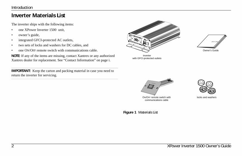
Inverter Materials ListThe inverter ships with the following items:• one XPower Inverter 1500 unit,• owner’s guide,• integrated GFCI-protected AC outlets, • two sets of locks and washers for DC cables, and • one ON/OFF remote switch with communications cable.NOTE: If any of the items are missing, contact Xantrex or any authorized Xantrex dealer for replacement. See “Contact Information” on page i.
IMPORTANT: Keep the carton and packing material in case you need to return the inverter for servicing.
Figure 1 Materials List
Inverterwith GFCI-protected outlets
Owner’s Guide
ON/OFF remote switch with communications cable
locks and washers
975-0558-01-01 3
Inverter FeaturesThis section describes the different parts of the inverter.
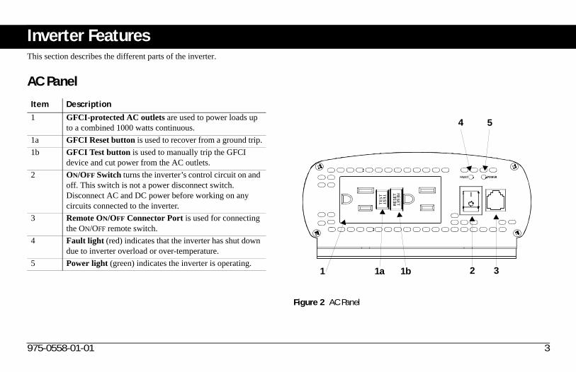
AC Panel
Item Description1 GFCI-protected AC outlets are used to power loads up
to a combined 1000 watts continuous.1a GFCI Reset button is used to recover from a ground trip.1b GFCI Test button is used to manually trip the GFCI
device and cut power from the AC outlets.2 ON/OFF Switch turns the inverter’s control circuit on and
off. This switch is not a power disconnect switch. Disconnect AC and DC power before working on any circuits connected to the inverter.
3 Remote ON/OFF Connector Port is used for connecting the ON/OFF remote switch.
4 Fault light (red) indicates that the inverter has shut down due to inverter overload or over-temperature.
5 Power light (green) indicates the inverter is operating.
Figure 2 AC Panel
4
3
5
1 1a 1b 2
4 XPower Inverter 1500 Owner’s Guide
Inverter Features
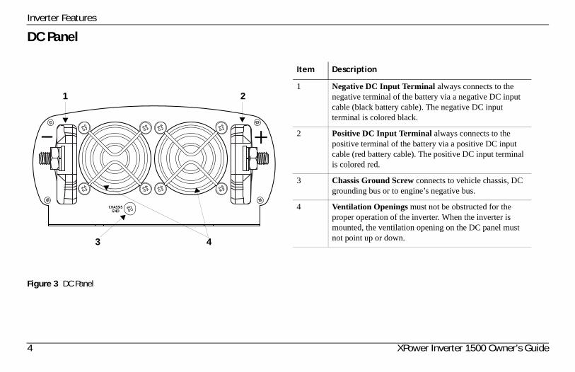
DC Panel
Figure 3 DC Panel
2
3
1
4
Item Description
1 Negative DC Input Terminal always connects to the negative terminal of the battery via a negative DC input cable (black battery cable). The negative DC input terminal is colored black.
2 Positive DC Input Terminal always connects to the positive terminal of the battery via a positive DC input cable (red battery cable). The positive DC input terminal is colored red.
3 Chassis Ground Screw connects to vehicle chassis, DC grounding bus or to engine’s negative bus.
4 Ventilation Openings must not be obstructed for the proper operation of the inverter. When the inverter is mounted, the ventilation opening on the DC panel must not point up or down.
975-0558-01-01 5
Inverter InstallationThis section describes general installation instructions for the XPower Inverter 1500 .
Installation CodeIn residential applications, electrical codes do not allow permanent connection of AC distribution wiring to the inverter’s GFCI-protected AC output receptacles. The receptacles are intended for temporary (as-needed) connection of cord connected loads only.
Prepare for Installation• Design your power system.• Calculate your battery requirements.• Choose an effective charging system.• Choose an appropriate location.• Purchase cables for DC input and ground.• Select the correct fuses (or circuit breakers).
IMPORTANT: Use a qualified installer if you do not possess the knowledge and skill necessary to follow these general instructions. In addition, a qualified installer such as a licensed electrician, knows all national and local electrical codes and specific installation codes that may apply to your power system design.

6 XPower Inverter 1500 Owner’s Guide
Inverter Installation
Typical Power System Design
Determine how you are going to use your inverter then design a power system that will give you maximum performance. The configuration shown below is a typical power system design applied in installing the inverter in recreational vehicles.
Battery Requirements
Battery type and battery size strongly affect the performance of the XPower Inverter 1500 . Therefore, you need to identify the type of loads your inverter will be powering and how much you will be using them between charges. Once you know how much power you will be using, you can determine how much battery capacity you need. Xantrex recommends that you purchase as much battery capacity as possible.
Charging System
The charging system must be appropriate for your particular installation. A well-designed charging system will ensure that power is available when you need it and that your batteries remain in top condition. Inadequate charging will degrade system performance and the wrong type of charger will reduce battery life.Contact Xantrex or visit www.xantrex.com to find more information about our different battery chargers.
Figure 4 Typical Power System Design
12V
12V
IMPORTANT: Connect the inverter to a 12-volt battery or 12-volt battery bank system. The inverter will not work on 6-volt battery systems and will be damaged when connected to a higher-than-12-volt battery system such as a 24-volt battery system in some trucks or recreational vehicles.
975-0558-01-01 7
Inverter Installation
Location
The XPower Inverter 1500 must only be installed in a location that is::
Cables for DC Input and Ground
To operate safely and effectively, use low-resistance wiring between the battery and the inverter because the inverter receives high-current input from a low-voltage battery.Run a chassis ground cable from the grounding point to the chassis ground screw on the inverter’s DC panel.When purchasing cables for DC input and ground:• Use a minimum No. 2 AWG for the DC input cable with a• Maximum cable length of 1.5 meters (5 feet), measured one-way from
battery terminal to inverter terminal.• Use a matching cable size for ground cable. Terminate one end with an
appropriately-sized ring connector.• Use stranded copper wires, avoiding aluminum wires due to their
higher-resistance rating.• Have your DC input cables crimped and terminated with
appropriately-sized ring connectors at the store of purchase.
Fuses (or Circuit Breakers)
Install only a DC-rated fuse (or a DC-rated circuit breaker) on the positive cable line as shown on Figure 4. When purchasing fuses (or circuit breakers), follow these recommendations.• Select a fuse (or circuit breaker) with a maximum rating of 150 Adc.• Determine the short-circuit current rating of the battery and• Choose a battery fuse that can withstand the short-circuit current that
may be generated by the battery.
Dry The inverter must be installed in a dry location not subject to moisture especially rain, spray, or splashing bilge water.
Cool The inverter should not be exposed to metal filings or any other form of contamination.
Ventilated The ambient air temperature should be between 0 – 40 °C (32 – 104 °F) for best performance.
Safe Ventilation openings on the inverter must not be obstructed. If the inverter is mounted in a tight fitting compartment, the compartment must be ventilated with cut-outs to prevent the inverter from overheating.
Close to battery
The inverter is not ignition-protected equipment, so it cannot be installed in areas containing gasoline tanks or fittings which require ignition-protected equipment. Xantrex recommends that it is safest not to install any kind of electrical equipment including the inverter in these areas.
Protected from battery gases
The inverter should be installed as close as possible to the batteries, but not in the same compartment to prevent corrosion. Avoid excessive cable lengths and use the recommended wire sizes. Xantrex recommends installing with cables sized to achieve less than 3% voltage drop on battery cables under full load. This will maximize the performance of the inverter.
8 XPower Inverter 1500 Owner’s Guide
Inverter Installation
Install the InverterReview and follow the safety guidelines in “Important Safety Instructions” on page iv before proceeding with installation.
Overview of Installation Steps• Mount the inverter.• Connect the chassis ground.• Connect the DC cables.
Mount the Inverter
1. Make sure the inverter’s ON/OFF switch is in the Off position.2. Select an appropriate mounting location and orientation. The inverter
must be oriented in one of the following ways:• Horizontally on a vertical surface. (The ventilation opening on
the DC end must not point up or down.)• On or under a horizontal surface.
3. Hold the inverter against the mounting surface, mark the positions of the mounting screws, and then remove the inverter.
4. Pilot drill the four mounting holes.5. Fasten the inverter to the mounting surface using corrosion-resistant
fasteners sized #10 or larger.
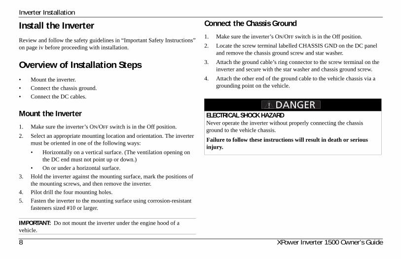
Connect the Chassis Ground
1. Make sure the inverter’s ON/OFF switch is in the Off position.2. Locate the screw terminal labelled CHASSIS GND on the DC panel
and remove the chassis ground screw and star washer.3. Attach the ground cable’s ring connector to the screw terminal on the
inverter and secure with the star washer and chassis ground screw.4. Attach the other end of the ground cable to the vehicle chassis via a
grounding point on the vehicle.
IMPORTANT: Do not mount the inverter under the engine hood of a vehicle.
ELECTRICAL SHOCK HAZARDNever operate the inverter without properly connecting the chassis ground to the vehicle chassis.Failure to follow these instructions will result in death or serious injury.
975-0558-01-01 9
Inverter Installation
Connect the DC Cables
1. Make sure the inverter’s ON/OFF switch is in the Off position.2. Working on the inverter’s positive DC input terminal first, attach one
end of the positive DC input cable to the positive DC input terminal on the inverter.
3. Attach a fuse holder (with an installed fuse) to the other end of the positive battery cable.Alternatively, if you are using a circuit breaker, install the circuit breaker on the positive terminal of the battery.
4. Attach the fused end on the positive DC input cable to the positive terminal of the battery.Alternatively, if you are using a circuit breaker, attach the other end of the positive DC input cable to the circuit breaker on the battery.
5. Working on the inverter’s negative DC input terminal, attach one end of the negative DC input cable to the negative DC input terminal on the inverter.
IMPORTANT: Before proceeding, make sure that your DC input cables are properly terminated with ring connectors appropriate for the size of the cable you are using. Have your cables terminated at the store of purchase.
IMPORTANT: Do not over tighten the nut on the inverter terminal. Damage to the inverter terminal may result. However, loose connections can cause excessive voltage drop and may cause overheated wires and melted insulation. A torque of 6.3–6.6 foot pounds (8.5–9.0 Nm) is sufficient.Use the above guidelines when tightening the nuts on both the inverter and battery terminals.
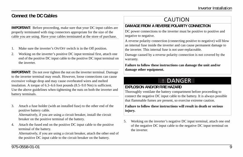
DAMAGE FROM A REVERSE POLARITY CONNECTIONDC power connections to the inverter must be positive to positive and negative to negative.A reverse polarity connection (connecting positive to negative) will blow an internal fuse inside the inverter and can cause permanent damage to the inverter. This internal fuse is not user-replaceable.Damage caused by a reverse polarity connection is not covered by the warranty.
Failure to follow these instructions can damage the unit and/or damage other equipment.
EXPLOSION AND/OR FIRE HAZARDThoroughly ventilate the battery compartment before proceeding to connect the negative DC input cable to the battery. It is always possible that flammable fumes are present, so exercise extreme caution.Failure to follow these instructions will result in death or serious injury.
10 XPower Inverter 1500 Owner’s Guide
Inverter Installation
6. Attach the other end of the negative DC input cable to the negative terminal of the battery.If you have installed a battery selector switch, set it to Off when making the connection to prevent sparking.NOTE: This the last cable connection. A spark is normal when you make this connection to the battery without a battery selector switch.If you have installed a battery selector switch, use it to select one of the batteries or battery banks (house bank preferred over start bank).
7. Move the inverter’s ON/OFF switch to the On position.The Power light should illuminate, indicating that the inverter is ready for operation.
975-0558-01-01 11
Inverter OperationThis section explains how to operate the inverter efficiently and effectively: • Gives procedures for operating the inverter from the front panel • Discusses operating limits and inverter loads• Discusses battery charging frequency• Provides information about routine maintenance
Turning the Inverter ON and OFF
The ON/OFF switch on the inverter’s front panel is the main ON/OFF switch that turns the control circuit in the inverter on and off.To turn the inverter on and off from its front panel:• Move the ON/OFF switch to the On position to turn the inverter on.• Move the ON/OFF switch to the Off position to turn the inverter off.
When the switch is Off, the inverter draws a very low current from the battery. See important note below.
To turn the inverter on and off from the remote switch:• Make sure the main ON/OFF switch on the front panel is turned on.• Move the remote ON/OFF switch to the On position to turn the inverter
on.• Move the remote ON/OFF switch to the Off position to turn the inverter
off.When the remote switch is Off, the inverter draws a very low current from the battery.
ELECTRICAL SHOCK HAZARDThe inverter’s ON/OFF switch does not disconnect DC battery power from the inverter. You must disconnect AC and DC power before working on any circuits connected to the inverter.Failure to follow these instructions can result in death or serious injury.
IMPORTANT: The inverter draws less than 300 mA from the battery with the main ON/OFF switch turned on and no load connected. If the main switch is left on, even with no loads the inverter will eventually discharge the battery.To prevent unnecessary battery discharge, turn the inverter off when you are not using it
12 XPower Inverter 1500 Owner’s Guide
Inverter Operation
Testing the GFCIPerform the following GFCI Test:1. Turn the inverter on.2. Plug a simple appliance, such as a lamp, in the GFCI outlet. Turn the
lamp on.3. Press the TEST button. Observe a clicking sound. The lamp turns off.4. Press the RESET button all the way to the bottom until the button
locks into position. The lamp turns back on.
Operating Several Loads at OnceIf you are going to operate several loads from the inverter, turn the loads on one at a time after you have turned the inverter on. Turning loads on separately helps to ensure that the inverter does not have to deliver the starting current for all the loads at once, and will help prevent an overload shutdown.
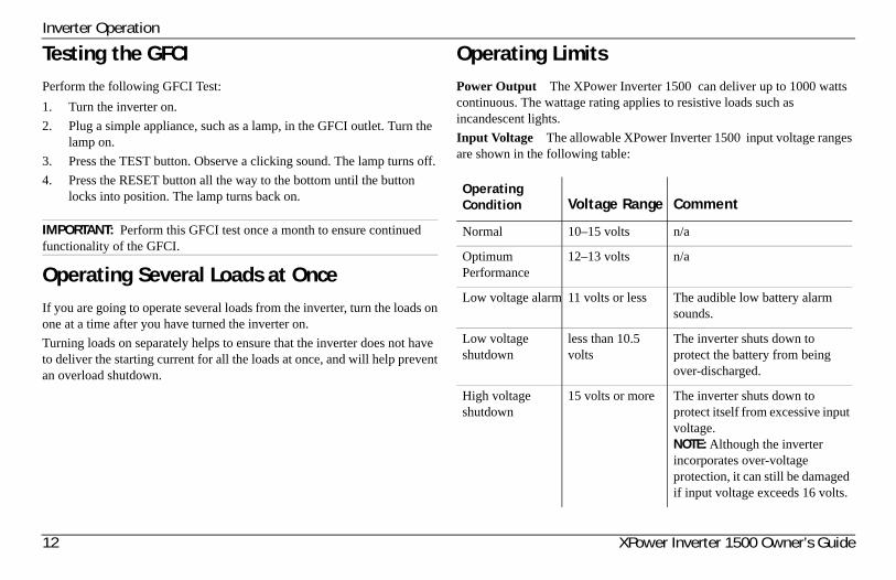
Operating LimitsPower Output The XPower Inverter 1500 can deliver up to 1000 watts continuous. The wattage rating applies to resistive loads such as incandescent lights. Input Voltage The allowable XPower Inverter 1500 input voltage ranges are shown in the following table:
IMPORTANT: Perform this GFCI test once a month to ensure continued functionality of the GFCI.
Operating Condition Voltage Range Comment
Normal 10–15 volts n/a
Optimum Performance
12–13 volts n/a
Low voltage alarm 11 volts or less The audible low battery alarm sounds.
Low voltage shutdown
less than 10.5 volts
The inverter shuts down to protect the battery from being over-discharged.
High voltage shutdown
15 volts or more The inverter shuts down to protect itself from excessive input voltage.NOTE: Although the inverter incorporates over-voltage protection, it can still be damaged if input voltage exceeds 16 volts.
975-0558-01-01 13
Inverter Operation
Inverter LoadsThe XPower Inverter 1500 will operate most AC loads within its power rating. However, some appliances and equipment may be difficult to operate, and other appliances may actually be damaged if you try to operate them with the inverter. Please read “High Surge Loads” and “Trouble Loads” carefully.
High Surge Loads
Some induction motors used in freezers, pumps, and other motor-operated equipment require high surge currents to start. The inverter may not be able to start some of these motors even though their rated current draw is within the inverter’s limits. The inverter will normally start single-phase induction motors rated at 1/2 horsepower or less.
Trouble Loads
Some equipment may be damaged by the inverter’s modified sine wave output.Some appliances, including the types listed below, may be damaged if they are connected to the inverter:• Electronics that modulate RF (radio frequency) signals on the AC line
will not work and may be damaged.• Speed controllers found in some fans, power tools, kitchen appliances,
and other loads may be damaged.
• Some chargers for small rechargeable batteries can be damaged. See “Precautions For Using Rechargeable Appliances” on page viii for details.
• Metal halide arc (HMI) lights can be damaged.• If you are unsure about powering any device with the inverter, contact
the manufacturer of the device.
Connecting Appliances to the InverterSince regular amounts of AC current flows between the inverter and your appliances, commonly available extension cords can be used to connect the inverter to your appliances. If your appliance will be connected at a considerable distance from the inverter, it is much more practical and less expensive to lengthen the AC wiring than it is to lengthen the DC wiring.
Routine Maintenance
Maintaining the Inverter
Minimal maintenance is required to keep your inverter operating properly. Periodically you should:• clean the exterior of the unit with a damp cloth to prevent the
accumulation of dust and dirt,• ensure that the DC cables are secure and fasteners are tight, and• make sure the ventilation openings on the DC panel and bottom of the
inverter are not clogged.
14 XPower Inverter 1500 Owner’s Guide
Inverter Operation
Recharging batteries
When possible, recharge your batteries when they are about 50% discharged or earlier. This gives the batteries a much longer life cycle than recharging when they are more deeply discharged.The XPower Inverter 1500 has a battery low voltage shutdown at 10.5Vdc. With moderate to heavy loads, this will protect against over-discharging the battery. If the inverter is running only light loads it is advisable to recharge before the inverter low voltage shutdown point is reached.For more information on maintaining batteries, consult your battery’s manufacturer.For information about Xantrex battery chargers, see our web site at www.xantrex.com.
Testing the GFCI
Perform a monthly test of the GFCI. See “Testing the GFCI” on page 12 for instructions.
975-0558-01-01 15
TroubleshootingThis section describes the most common problems you may encounter with the operation of the inverter along with resolutions.If you encounter problems other than what is described in this section, contact customer support at the number listed on “Contact Information” on page i.
Common Problems
Buzz in Audio Equipment
Some inexpensive stereo systems may emit a buzzing noise from their loudspeakers when operated from the inverter. This occurs because the power supply in the audio system does not adequately filter the modified sine wave produced by the inverter. The only solution is to use a sound system that has a higher quality power supply.
Television Reception
When the inverter is operating, it can interfere with television reception on some channels. If interference occurs, try the following:1. Make sure that the chassis ground screw on the rear of the inverter is
solidly connected to the ground system of your vehicle or home.2. Make sure that the television antenna provides an adequate (“snow-
free”) signal, and that you are using good quality cable between the antenna and the television.
3. Keep the cables between the battery and the inverter as short as possible, and twist them together with two to three twists per foot. (This minimizes radiated interference from the cables.)
4. Move the television as far away from the inverter as possible.5. Do not operate high power loads with the inverter while the television
is on.
16 XPower Inverter 1500 Owner’s Guide
Troubleshooting
Troubleshooting Reference
NOTE: See table on the following page.
ELECTRICAL SHOCK HAZARDDo not disassemble the XPower Inverter 1500 . It does not contain any user-serviceable parts.
Failure to follow these instructions can result in death or serious injury.
975-0558-01-01 17
Troubleshooting
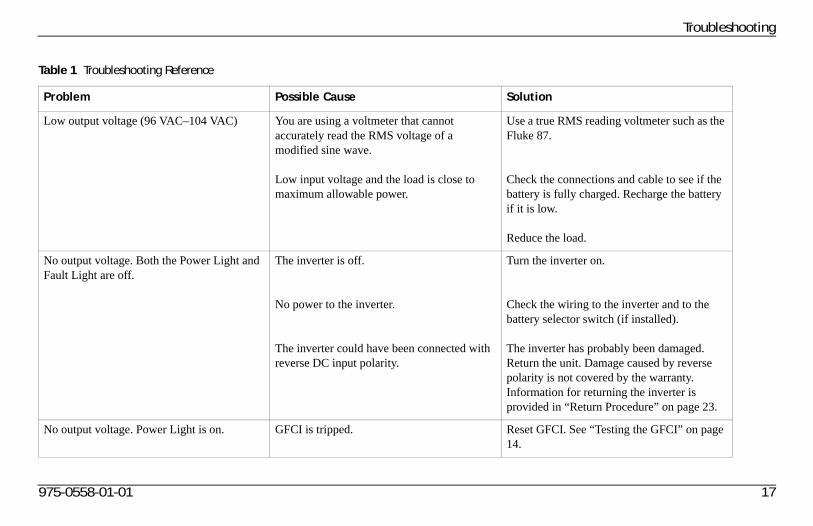
Table 1 Troubleshooting Reference
Problem Possible Cause Solution
Low output voltage (96 VAC–104 VAC) You are using a voltmeter that cannot accurately read the RMS voltage of a modified sine wave.
Low input voltage and the load is close to maximum allowable power.
Use a true RMS reading voltmeter such as the Fluke 87.
Check the connections and cable to see if the battery is fully charged. Recharge the battery if it is low.
Reduce the load.
No output voltage. Both the Power Light and Fault Light are off.
The inverter is off.
No power to the inverter.
The inverter could have been connected with reverse DC input polarity.
Turn the inverter on.
Check the wiring to the inverter and to the battery selector switch (if installed).
The inverter has probably been damaged. Return the unit. Damage caused by reverse polarity is not covered by the warranty. Information for returning the inverter is provided in “Return Procedure” on page 23.
No output voltage. Power Light is on. GFCI is tripped. Reset GFCI. See “Testing the GFCI” on page 14.
18 XPower Inverter 1500 Owner’s Guide
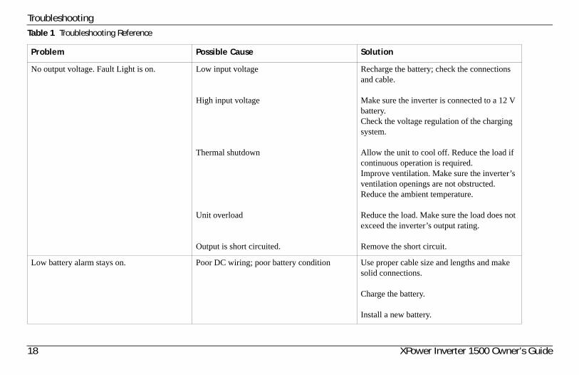
Troubleshooting
No output voltage. Fault Light is on. Low input voltage
High input voltage
Thermal shutdown
Unit overload
Output is short circuited.
Recharge the battery; check the connections and cable.
Make sure the inverter is connected to a 12 V battery.Check the voltage regulation of the charging system.
Allow the unit to cool off. Reduce the load if continuous operation is required.Improve ventilation. Make sure the inverter’s ventilation openings are not obstructed. Reduce the ambient temperature.
Reduce the load. Make sure the load does not exceed the inverter’s output rating.
Remove the short circuit.
Low battery alarm stays on. Poor DC wiring; poor battery condition Use proper cable size and lengths and make solid connections.
Charge the battery.
Install a new battery.
Table 1 Troubleshooting Reference
Problem Possible Cause Solution
975-0558-01-01 19
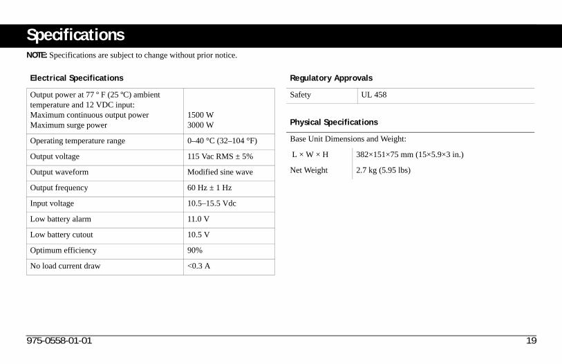
SpecificationsNOTE: Specifications are subject to change without prior notice.
Electrical Specifications
Output power at 77 º F (25 ºC) ambient temperature and 12 VDC input:Maximum continuous output power Maximum surge power
1500 W3000 W
Operating temperature range 0–40 °C (32–104 °F)
Output voltage 115 Vac RMS ± 5%
Output waveform Modified sine wave
Output frequency 60 Hz ± 1 Hz
Input voltage 10.5–15.5 Vdc
Low battery alarm 11.0 V
Low battery cutout 10.5 V
Optimum efficiency 90%
No load current draw <0.3 A
Regulatory Approvals
Safety UL 458
Physical Specifications
Base Unit Dimensions and Weight:
L × W × H 382×151×75 mm (15×5.9×3 in.)
Net Weight 2.7 kg (5.95 lbs)
20 XPower Inverter 1500 Owner’s Guide
Warranty and Return Information
WarrantyWhat does this warranty cover and how long does it last? This Limited Warranty is provided by Xantrex Technology Inc. (“Xantrex”) and covers defects in workmanship and materials in your XPower Inverter 1500 . This warranty period lasts for 24 months from the date of purchase at the point of sale to you, the original end user customer, unless otherwise agreed in writing (the “Warranty Period”). You will be required to demonstrate proof of purchase to make warranty claims.This Limited Warranty is transferable to subsequent owners but only for the unexpired portion of the Warranty Period. Subsequent owners also require original proof of purchase as described in “What proof of purchase is required?”What will Xantrex do? During the Warranty Period Xantrex will, at its option, repair the product (if economically feasible) or replace the defective product free of charge, provided that you notify Xantrex of the product defect within the Warranty Period, and provided that Xantrex through inspection establishes the existence of such a defect and that it is covered by this Limited Warranty. Xantrex will, at its option, use new and/or reconditioned parts in performing warranty repair and building replacement products. Xantrex reserves the right to use parts or products of original or improved design in the repair or replacement. If Xantrex repairs or replaces a product, its warranty continues for the remaining portion of the original Warranty Period or 90 days from the date of the return shipment to the customer, whichever is greater. All replaced products and all parts removed from repaired products become the property of Xantrex.Xantrex covers both parts and labor necessary to repair the product, and return shipment to the customer via a Xantrex-selected non-expedited surface freight within the contiguous United States and Canada. Alaska,
Hawaii and outside of the United States and Canada are excluded. Contact Xantrex Customer Service for details on freight policy for return shipments from excluded areas.How do you get service? If your product requires troubleshooting or warranty service, contact your merchant. If you are unable to contact your merchant, or the merchant is unable to provide service, contact Xantrex directly at:
Direct returns may be performed according to the Xantrex Return Material Authorization Policy described in your product manual. For some products, Xantrex maintains a network of regional Authorized Service Centers. Call Xantrex or check our website to see if your product can be repaired at one of these facilities.
Telephone: 1 800 670 0707 (toll free North America)1 408 987 6030 (direct)
Fax: 1 800 994 7828 (toll free North America)Email: [email protected]: www.xantrex.com
975-0558-01-01 21
Warranty and Return InformationWhat proof of purchase is required? In any warranty claim, dated proof of purchase must accompany the product and the product must not have been disassembled or modified without prior written authorization by Xantrex. Proof of purchase may be in any one of the following forms:
• The dated purchase receipt from the original purchase of the product at point of sale to the end user; or
• The dated dealer invoice or purchase receipt showing original equipment manufacturer (OEM) status; or
• The dated invoice or purchase receipt showing the product exchanged under warranty.
What does this warranty not cover? Claims are limited to repair and replacement, or if in Xantrex's discretion that is not possible, reimbursement up to the purchase price paid for the product. Xantrex will be liable to you only for direct damages suffered by you and only up to a maximum amount equal to the purchase price of the product.This Limited Warranty does not warrant uninterrupted or error-free operation of the product or cover normal wear and tear of the product or costs related to the removal, installation, or troubleshooting of the customer's electrical systems. This warranty does not apply to and Xantrex will not be responsible for any defect in or damage to:a) the product if it has been misused, neglected, improperly installed,
physically damaged or altered, either internally or externally, or damaged from improper use or use in an unsuitable environment;
b) the product if it has been subjected to fire, water, generalized corrosion, biological infestations, or input voltage that creates operating conditions beyond the maximum or minimum limits listed in the Xantrex product specifications including but not limited to high input voltage from generators and lightning strikes;
c) the product if repairs have been done to it other than by Xantrex or its authorized service centers (hereafter “ASCs”);
d) the product if it is used as a component part of a product expressly warranted by another manufacturer;
e) component parts or monitoring systems supplied by you or purchased by Xantrex at your direction for incorporation into the product;
f) the product if its original identification (trade-mark, serial number) markings have been defaced, altered, or removed;
g) the product if it is located outside of the country where it was purchased; and
h) any consequential losses that are attributable to the product losing power whether by product malfunction, installation error or misuse.
22 XPower Inverter 1500 Owner’s Guide
Warranty and Return Information
Disclaimer
ProductTHIS LIMITED WARRANTY IS THE SOLE AND EXCLUSIVE WARRANTY PROVIDED BY XANTREX IN CONNECTION WITH YOUR XANTREX PRODUCT AND IS, WHERE PERMITTED BY LAW, IN LIEU OF ALL OTHER WARRANTIES, CONDITIONS, GUARANTEES, REPRESENTATIONS, OBLIGATIONS AND LIABILITIES, EXPRESS OR IMPLIED, STATUTORY OR OTHERWISE IN CONNECTION WITH THE PRODUCT, HOWEVER ARISING (WHETHER BY CONTRACT, TORT, NEGLIGENCE, PRINCIPLES OF MANUFACTURER'S LIABILITY, OPERATION OF LAW, CONDUCT, STATEMENT OR OTHERWISE), INCLUDING WITHOUT RESTRICTION ANY IMPLIED WARRANTY OR CONDITION OF QUALITY, MERCHANTABILITY OR FITNESS FOR A PARTICULAR PURPOSE. ANY IMPLIED WARRANTY OF MERCHANTABILITY OR FITNESS FOR A PARTICULAR PURPOSE TO THE EXTENT REQUIRED UNDER APPLICABLE LAW TO APPLY TO THE PRODUCT SHALL BE LIMITED IN DURATION TO THE PERIOD STIPULATED UNDER THIS LIMITED WARRANTY.IN NO EVENT WILL XANTREX BE LIABLE FOR: (A) ANY SPECIAL, INDIRECT, INCIDENTAL OR CONSEQUENTIAL DAMAGES, INCLUDING LOST PROFITS, LOST REVENUES, FAILURE TO REALIZE EXPECTED SAVINGS, OR OTHER COMMERCIAL OR ECONOMIC LOSSES OF ANY KIND, EVEN IF XANTREX HAS BEEN ADVISED, OR HAD REASON TO KNOW, OF THE POSSIBILITY OF SUCH DAMAGE; (B) ANY LIABILITY ARISING IN TORT, WHETHER OR NOT ARISING OUT OF XANTREX'S NEGLIGENCE, AND ALL LOSSES OR DAMAGES TO ANY PROPERTY OR FOR ANY PERSONAL INJURY OR ECONOMIC LOSS OR DAMAGE CAUSED BY THE CONNECTION OF A PRODUCT TO ANY OTHER DEVICE OR SYSTEM; AND (C) ANY DAMAGE OR INJURY ARISING FROM OR AS A RESULT OF MISUSE OR ABUSE, OR THE INCORRECT INSTALLATION, INTEGRATION OR OPERATION OF THE PRODUCT BY PERSONS NOT AUTHORIZED BY XANTREX.
ExclusionsIF THIS PRODUCT IS A CONSUMER PRODUCT, FEDERAL LAW DOES NOT ALLOW AN EXCLUSION OF IMPLIED WARRANTIES. TO THE EXTENT YOU ARE ENTITLED TO IMPLIED WARRANTIES UNDER FEDERAL LAW, TO THE EXTENT PERMITTED BY APPLICABLE LAW THEY ARE LIMITED TO THE DURATION OF THIS LIMITED WARRANTY. SOME STATES, PROVINCES AND JURISDICTIONS DO NOT ALLOW LIMITATIONS OR EXCLUSIONS ON IMPLIED WARRANTIES OR ON THE DURATION OF AN IMPLIED WARRANTY OR ON THE LIMITATION OR EXCLUSION OF INCIDENTAL OR CONSEQUENTIAL DAMAGES, SO THE ABOVE LIMITATION(S) OR EXCLUSION(S) MAY NOT APPLY TO YOU. THIS LIMITED WARRANTY GIVES YOU SPECIFIC LEGAL RIGHTS. YOU MAY HAVE OTHER RIGHTS WHICH MAY VARY FROM STATE TO STATE, PROVINCE TO PROVINCE OR JURISDICTION TO JURISDICTION.
975-0558-01-01 23
Warranty and Return Information
Return Material Authorization PolicyFor those products that are not being repaired in the field and are being returned to Xantrex, before returning a product directly to Xantrex you must obtain a Return Material Authorization (RMA) number and the correct factory “Ship To” address. Products must also be shipped prepaid. Product shipments will be refused and returned at your expense if they are unauthorized, returned without an RMA number clearly marked on the outside of the shipping box, if they are shipped collect, or if they are shipped to the wrong location.When you contact Xantrex to obtain service, please have your instruction manual ready for reference and be prepared to supply:
• The serial number of your product• Information about the installation and use of the unit• Information about the failure and/or reason for the return• A copy of your dated proof of purchase
Record these details on page 24.
Return ProcedurePackage the unit safely, preferably using the original box and packing materials. Please ensure that your product is shipped fully insured in the original packaging or equivalent. This warranty will not apply where the product is damaged due to improper packaging.Include the following:
• The RMA number supplied by Xantrex Technology Inc. clearly marked on the outside of the box.
• A return address where the unit can be shipped. Post office boxes are not acceptable.
• A contact telephone number where you can be reached during work hours.
• A brief description of the problem.Ship the unit prepaid to the address provided by your Xantrex customer service representative.
If you are returning a product from outside of the USA or Canada In addition to the above, you MUST include return freight funds and are fully responsible for all documents, duties, tariffs, and deposits. If you are returning a product to a Xantrex Authorized Service Center (ASC) A Xantrex return material authorization (RMA) number is not required. However, you must contact the ASC prior to returning the product or presenting the unit to verify any return procedures that may apply to that particular facility and that the ASC repairs this particular Xantrex product.
24 XPower Inverter 1500 Owner’s Guide
Warranty and Return Information
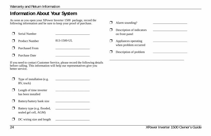
Information About Your SystemAs soon as you open your XPower Inverter 1500 package, record the following information and be sure to keep your proof of purchase.
If you need to contact Customer Service, please record the following details before calling. This information will help our representatives give you better service.
❐ Serial Number ______________________
❐ Product Number 813-1500-UL
❐ Purchased From ______________________
❐ Purchase Date ______________________
❐ Type of installation (e.g. RV, truck)
______________________
❐ Length of time inverter has been installed
______________________
❐ Battery/battery bank size ______________________
❐ Battery type (e.g. flooded, sealed gel cell, AGM)
______________________
❐ DC wiring size and length ______________________
❐ Alarm sounding? ______________________
❐ Description of indicators on front panel
______________________
❐ Appliances operating when problem occurred
______________________
❐ Description of problem ______________________
________________________________________________


Xantrex Technology Inc.
1 800 670 0707 Tel toll free1 408 987 6030 Tel direct1 800 994 7828 Fax toll [email protected]
975-0558-01-01 Printed in China.