owner’s guide - total gym gym gts... · thank you for purchasing gts®, the center of the...
TRANSCRIPT

GTS® OWNER’S GUIDE
OWNE
R’S
GUID
EGT
S®
800
541
4900
EFIS
PORT
SMED
ICIN
E.CO
M

Thank you for purchasing GTS®, the center of the GRAVITYSystem® and anchor for the comprehensiveGRAVITY4Programming®. Your GTS is an investment that will enhance your business year after year.
Please read and save your Owner’s Guide so that you may refer to it in the future.
Your GTS® arrives with very little required in the way of assembly. Simply follow this Guide and yourGTS® will be operational.
In this Guide you will find tips about GTS and its component parts, operation, maintenance and care. Additionally, you will find safety tips and precautions to help ensure your safety and the safety of yourclientele in a commercial setting. Also included is a description of your warranty information.
If during the course of using the GTS you have any questions about the product or you require parts orservice, please write, email or call us at the address or phone number listed below.
Our goal is to support your success through the GRAVITYSystem®, and we stand ready to help you everystep of the way.
Sincerely,
President/CEO
efi Sports Medicine7755 Arjons DriveSan Diego, CA 92126
U.S.A. area code (858) 586-6080800 541 4900 toll-free inside [email protected]
CAUTION: As with any exercise program, participants should consult a physician before starting a workout on GTS.
CONGRATULATIONS
©20
05,e
fiCo
rpor
atio
n.

OWNE
R’S
GUID
EGT
S®
800
541
4900
EFIS
PORT
SMED
ICIN
E.CO
M
3
NOTE: Letters in (parentheses) refer to the PARTSIDENTIFIER on page 3 and/or the PARTS GTS® OWNER’S GUIDE
OWNE
R’S
GUID
EGT
S®
800
541
4900
EFIS
PORT
SMED
ICIN
E.CO
M
3
C
INSET 1 (REAR TOWER VIEW)
W
X (see INSET 8)
T
B (on back of Tower; see INSET 1)
E (see INSET 3)
A. Tower
B. Tower Top Handle
C. Tower Pulley Pocket
D. Tower Lock Pin
E. Folding Foot Holder
E1. Upper Foot Pad Assembly
E2. Lower Foot Pad Assembly
F. Glideboard “D” Ring
G. Glideboard
H. Telescoping Squat Stand
I. Folding Platform
J. Lower Rail Base
K. Lower Rails
L. Glideboard Wheel Housing
M. Support Strut Knob
N. Upper Rails
O. Support Strut
P. Transport Wheels
Q. Tower Base
R. Tower Level Hooks
S. Tower Back Handle
T. Handles
U. Center Rail Crossbar
V. Rectangular Bushings
W. Dynamic Arm Pulley System
X. Pulley Locator Brackets
Y. Lateral Adjustable Training (LAT) Bars
Z. Tower Crossbar (see inset 9;located inside back tower cover)
Y
C (on top of Tower; see INSET 1)
INSET 8
INSET 7 (REAR TOWER VIEW)
INSET 3
B
PARTS IDENTIFIER - GTS
X
V
E1
E2
F
S
D
F (see INSET 4)
INSET 4
V (On back of Upper Rails; see INSET 3)
S (On back of Tower; see INSET 5)
INSET 5
U (see INSET 6)
U
INSET 2
INSET 6
INSET 9
D (see INSET 2)
^ G
A
Q
^
^
H
JI
K
M
^ ^ ^^P
N
OLR
Z
^^ When parts are referenced throughout this guide,
corresponding letters from this PARTS IDENTIFIER page arealso listed. For example, when “Tower” appears within thisguide, (A) will appear behind “Tower” as a cue to refer backto this page if needed.

PARTS ASSEMBLY - GTSYour GTS arrives with some assembly required.
HARDWARE PACKET CONTENTS
AA. Tower, Rail & Glideboard Assembly
BOX CONTENTS
BB. LAT Bars & Arm Pulley Cable Assembly
CC. Folding Platform DD. Telescoping Squat Stand
EE. Empty Spacer Box FF. One Hardware Packet Box
MM. Handles (2)LL. GTS Owner’s Guide (1)KK. Quick Links (2)
JJ. Socket Head Screws (2)II. Chrome Washers (2)HH. Bronze Washers (4)GG. Wrenches (2)

OWNE
R’S
GUID
EGT
S®
800
541
4900
EFIS
PORT
SMED
ICIN
E.CO
M
5
GTS® OWNER’S GUIDE
OWNE
R’S
GUID
EGT
S®
800
541
4900
EFIS
PORT
SMED
ICIN
E.CO
M
5
1
2
3
4 5
SET UP - GTS
1. Remove your GTS from the box. Stand the GTS upright. Never turn your GTS on its side.Assemble and use the GTS on flat ground.
NOTE: Required floor space for operation of GTS:3.5 ft. x 9.5 ft [1m x 3m] W/L
SET UP - GTS: UNFOLDING
2. Disengage the Tower Lock Pin (D).
3. Store the Tower Lock Pin (D) in the Lock PinBracket on the Support Strut (O) as shown.
4-5. Gently pull Lower Rail Base (J) away from Tower Base (Q), twist the retractable SupportStrut Knob (M) to loosen it.
NOTE: Letters in (parentheses) refer to the PARTS IDENTIFIER on page 3 and/or the PARTS ASSEMBLY on page 4. Use as needed for clarification.

NOTE: Letters in (parentheses) refer to the PARTS IDENTIFIER on page 3 and/or the PARTS ASSEMBLY on page 4. Use as needed for clarification.
hold
6
8
10
12
7
9
11
13
Lift
Pull
SET UP - GTS: UNFOLDING (CONTINUED)
6. Hold the padded Center Rail Crossbar (U).
7. Hold the Tower (A), while continuing to hold the Center Rail Crossbar (U).
8. Allow the Rails (K, N) to unfold, away from the Tower (A)until the Rails (K, N) are fully extended. Continue holdingthe Tower (A).
9-10. Raise the Rails (K, N) to level 3. Tilt Tower (A) slightlyforward, until the Support Strut Knob (M) pops intoposition. Tighten Support Strut Knob (M).
IMPORTANT SAFETY CONSIDERATION: Support Strut Knob (M)must be engaged and tightened while GTS is unfolded or in use.
CAUTION: To avoid damage to your GTS, the Support StrutKnob (M) must be loosened and disengaged when folding.
REPOSITIONING GLIDEBOARD11. To reposition the Glideboard (G) for use, kneel beside the
Glideboard (G). First, lift and pop one side of the metalGlideboard Wheel Housing (L) away from the Rails (K, N).
12. Disengage the Glideboard (G).
13. Move the Glideboard (G) about 6 inches up the Rails (K, N)toward the Tower (A), until the metal stop on the undersideof the Glideboard (G) rests above the rubber bumper on the Lower Rail (K). Lower the Glideboard (G) and pop theGlideboard Wheel Housing (L) back into place.

OWNE
R’S
GUID
EGT
S®
800
541
4900
EFIS
PORT
SMED
ICIN
E.CO
M
7
GTS® OWNER’S GUIDE
OWNE
R’S
GUID
EGT
S®
800
541
4900
EFIS
PORT
SMED
ICIN
E.CO
M
7
Figure 4a
15
16
17
18
14INSTALL LAT BARS
14. With one hand holding the padded Center RailCrossbar (U) and another on the Tower (A), raisethe rails to Tower (A) level 5 or 6 for ease of assembly, as shown.
15. Ensure that the Support Strut Knob (M) is engaged and tight.
REMOVE THE SHIPPING SLEEVES - PHASE 116. Your GTS arrives with shipping sleeves on the ends
of the Tower Crossbar (Z). The shipping sleevesserve one purpose: to protect the tower crossbarduring shipping.
17. To remove the first shipping sleeve, face the backof the Tower (A) and take one of the suppliedwrenches in each hand.
NOTE: For easiest assembly, keep the TowerCrossbar (Z) centered throughout the assemblyprocess, with each end extending about equaldistance from the Tower (A).
18. Apply one Wrench (GG) to the nyloc nut on one side of the Tower Crossbar (Z) to immobilize theCrossbar. Use the other Wrench (GG) to loosen thenyloc nut by turning counterclockwise.
NOTE: Letters in (parentheses) refer to the PARTS IDENTIFIER on page 3 and/or the PARTS ASSEMBLY on page 4. Use as needed for clarification.

NOTE: Letters in (parentheses) refer to the PARTS IDENTIFIER on page 3 and/or the PARTS ASSEMBLY on page 4. Use as needed for clarification.
19
20
21
22 23
shipping sleeve
INSTALL LAT BARS (CONTINUED)
19. Remove the nyloc nut, Chrome Washer (II) and the Bronze Washer (HH). Set them aside.
20. Hold the Upper Rail (N) with one hand. Remove the first shipping sleeve from the TowerCrossbar (Z) with the other hand. Set the first shipping sleeve aside.
21. To remove the remaining shipping sleeve, immobilize the exposed end of the Tower Crossbar (Z)by applying one of the Wrenches (GG) to the notch.
22. Use the other Wrench (GG) to loosen the remaining nyloc nut by turning it counterclockwise.
23. Hold the Upper Rail (N) with one hand. Remove the second shipping sleeve from the TowerCrossbar (Z) with the other hand. Set the shipping sleeve aside. You may discard the shippingsleeves or retain them in the event you need to ship your GTS in the future.
Now that the shipping sleeves have been removed, you are ready to attach the first LAT Bar (Y).

OWNE
R’S
GUID
EGT
S®
800
541
4900
EFIS
PORT
SMED
ICIN
E.CO
M
9
GTS® OWNER’S GUIDE
OWNE
R’S
GUID
EGT
S®
800
541
4900
EFIS
PORT
SMED
ICIN
E.CO
M
9
Bronze Washer
24
25
26
27
INSTALL LAT BARS (CONTINUED)
POSITION THE LAT BARS - PHASE 224. To position the first LAT Bar (Y) for mounting, make sure the long, vertical side of the LAT Bar
(Y) aligns closest to the Tower (A). NOTE: The slotted holes face the back of the GTS, the blackknob faces the Glideboard (G).
25. Slide a Bronze Washer (HH) onto the LAT Bar cylinder.
26. Stand beside the tower and align the LAT Bar cylinder with the Tower Crossbar (Z). REMINDER: Keep the Tower Crossbar (Z) centered during assembly. Slide the LAT Bar cylinderonto the Tower Crossbar (Z) until it is securely seated on the Upper Rail (N).
27. Rotate the LAT Bar upside-down until the other LAT Bar is installed, and both nuts on the Tower Crossbar (Z) have been tightened.
NOTE: Letters in (parentheses) refer to the PARTS IDENTIFIER on page 3 and/or the PARTS ASSEMBLY on page 4. Use as needed for clarification.
black knob
NOTE: Letters in (parentheses) refer to the PARTS IDENTIFIER on page 3 and/or the PARTS ASSEMBLY on page 4. Use as needed for clarification.
28
29
30
31
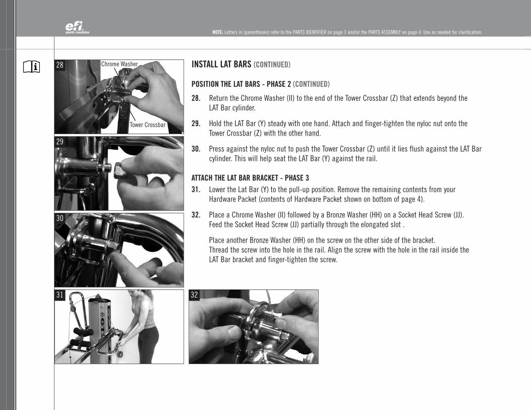
INSTALL LAT BARS (CONTINUED)
POSITION THE LAT BARS - PHASE 2 (CONTINUED)
28. Return the Chrome Washer (II) to the end of the Tower Crossbar (Z) that extends beyond the LAT Bar cylinder.
29. Hold the LAT Bar (Y) steady with one hand. Attach and finger-tighten the nyloc nut onto theTower Crossbar (Z) with the other hand.
30. Press against the nyloc nut to push the Tower Crossbar (Z) until it lies flush against the LAT Barcylinder. This will help seat the LAT Bar (Y) against the rail.
ATTACH THE LAT BAR BRACKET - PHASE 331. Lower the Lat Bar (Y) to the pull-up position. Remove the remaining contents from your
Hardware Packet (contents of Hardware Packet shown on bottom of page 4).
32. Place a Chrome Washer (II) followed by a Bronze Washer (HH) on a Socket Head Screw (JJ). Feed the Socket Head Screw (JJ) partially through the elongated slot .
Place another Bronze Washer (HH) on the screw on the other side of the bracket. Thread the screw into the hole in the rail. Align the screw with the hole in the rail inside the LAT Bar bracket and finger-tighten the screw.
32
Chrome Washer
Tower Crossbar

OWNE
R’S
GUID
EGT
S®
800
541
4900
EFIS
PORT
SMED
ICIN
E.CO
M
11
GTS® OWNER’S GUIDE
OWNE
R’S
GUID
EGT
S®
800
541
4900
EFIS
PORT
SMED
ICIN
E.CO
M
11
33
34
35
3736
INSTALL LAT BARS (CONTINUED)
ATTACH THE LAT BAR BRACKET - PHASE 3 (CONTINUED)33. Place another Bronze Washer (HH) on the screw on the other side of the bracket.
Thread the screw into the hole in the rail. Align the screw with the hole in the rail inside the LAT Bar bracket and finger tighten the screw.
34. Tighten the Socket Head Screw (JJ) with the hex end handle of the Wrench (GG).
REPEAT PHASE 2 - Position the LAT Bar (Y) on the opposite side.
REPEAT PHASE 3 - Attach the LAT Bar bracket on the opposite side.
Then use both Wrenches (GG) to tighten the nuts on the Tower Crossbar (Z) until the nut is flushwith the end of the shaft.
35. A counterweight system is housed inside your GTS Tower (A). After installing the LAT Bars (Y)and before exercising on your GTS, be sure to raise the rails to level 8 to re-center thecounterweight strap on the Tower Crossbar (Z).
Then check that the plastic Rectangular Bushings (V) are not tight against the Tower (A) sides.Hold the Rails (K, N) above the Tower Hook at level 8 and push the Tower (A) back with onehand, then let go. The Tower (A) should rock forward immediately. If the Tower (A) does not rockforward by itself, loosen the nyloc nuts on the Tower Crossbar (Z) and repeat the process. If thisdoesn’t correct the problem call efi Sports Medicine Customer Service.
With these steps (14 - 35) completed, your LAT Bars (BB) are assembled.
36. Attach the Handles (MM) to the cable ends using the Quick Links (KK).
37. Store the center pulley, when not in use, in the Tower Pulley Pocket (CC), located at the top of the Tower (A).
NOTE: Letters in (parentheses) refer to the PARTS IDENTIFIER on page 3 and/or the PARTS ASSEMBLY on page 4. Use as needed for clarification.
Socket Head Screw
NOTE: Letters in (parentheses) refer to the PARTS IDENTIFIER on page 3 and/or the PARTS ASSEMBLY on page 4. Use as needed for clarification.
38
39
40
41
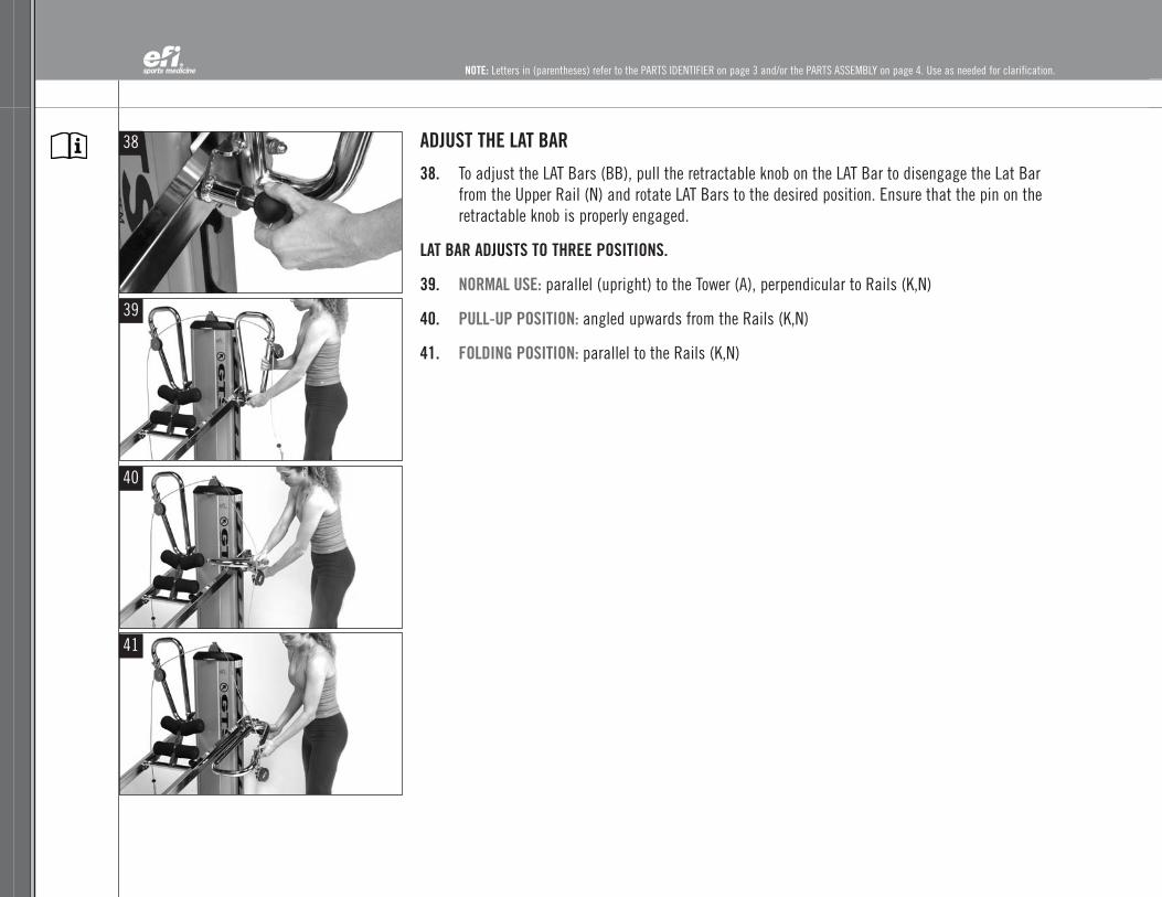
ADJUST THE LAT BAR
38. To adjust the LAT Bars (BB), pull the retractable knob on the LAT Bar to disengage the Lat Barfrom the Upper Rail (N) and rotate LAT Bars to the desired position. Ensure that the pin on theretractable knob is properly engaged.
LAT BAR ADJUSTS TO THREE POSITIONS.
39. NORMAL USE: parallel (upright) to the Tower (A), perpendicular to Rails (K,N)
40. PULL-UP POSITION: angled upwards from the Rails (K,N)
41. FOLDING POSITION: parallel to the Rails (K,N)

OWNE
R’S
GUID
EGT
S®
800
541
4900
EFIS
PORT
SMED
ICIN
E.CO
M
13
GTS® OWNER’S GUIDE
OWNE
R’S
GUID
EGT
S®
800
541
4900
EFIS
PORT
SMED
ICIN
E.CO
M
13
ADJUST THE RAIL ANGLE
To raise or lower the rail angle, stand alongside the Upper Rail (N), facing the Tower (A). Always haveone hand on the Tower (A) and one on the Upper Rail (N); lift the Rails (K, N) using proper lifting methods.
42. When you are raising the resistance level, lift the Rails (K, N) and slip the Tower Crossbar (Z)into the desired Tower Hook (R). The higher the Rails (K,N) are on the Tower (A), the higher the resistance. Once the Tower Crossbar (Z) connects with the desired Tower Hook (R), lower the Rails (K, N) and make sure that the Tower Crossbar (Z) is securely seated inside the Tower Hook (R).
HINT: At lower resistance levels, pulling the Tower (A) forward will help seat the Tower Crossbar(Z), and you can push downward on the Rails (K, N) to insure the Tower Crossbar (Z) is seated.
IMPORTANT: Be sure the Tower Crossbar (Z) is fully secured in the Tower Hooks (R) on bothsides before use. Always perform a visual and manual check before getting on the GTS.
43. When lowering the resistance level, lift the Rails (K, N) to disengage the Tower Crossbar (Z)from the Tower Hook (R). Push the Tower (A) back, and lower the Rails (K, N) to the desiredlevel. Once the Tower Crossbar (Z) aligns with the Tower Hook (R), pull the Tower (A) forwardand lower the Rails (K, N) until the Tower Crossbar (Z) is securely seated in the Tower Hook (R).Push down on the Rails (K, N) to insure the Tower Crossbar (Z) is seated.
ATTACH AND DETACH DYNAMIC ARM PULLEY CABLE SYSTEM (W)
44. To attach the Dynamic Arm Pulley System (W) to the Glideboard (G), remove the center pulleyfrom the Tower Pulley Pocket (C) and connect the snap hook to the Glideboard “D” Ring (F).
45. To free the Glideboard (G) from the Dynamic Arm Pulley System (W), simply unfasten andrelease the snap hook on the pulley, and store the center cable pulley in the Tower Pulley Pocket (C).
42
43
44
45
Tower Hook
NOTE: Letters in (parentheses) refer to the PARTS IDENTIFIER on page 3 and/or the PARTS ASSEMBLY on page 4. Use as needed for clarification.

NOTE: Letters in (parentheses) refer to the PARTS IDENTIFIER on page 3 and/or the PARTS ASSEMBLY on page 4. Use as needed for clarification.
FOLDING FOOT HOLDER (E)
46. Your GTS arrives with the Folding Foot Holder (E) attached. Remove the packing material.The Folding Foot Holder (E) must be rotated to the upright position for certain exercises.
47. To raise the Folding Foot Holder (E), simply pull up until the adjustment knob engages in the uprightposition.
48. To adjust the height of the Folding Foot Holder (E), push in the center post snap button and raise the Upper Foot Pad Assembly (E1). This allows individuals with longer feet to more easily positionthemselves in the Folding Foot Holder (E).
49. To begin using the Folding Foot Holder (E), sit at the top of the Glideboard (G) and place your heels pastthe pads of the Lower Foot Pad Assembly (E2).
50. If you have adjusted the Upper Foot Pad Assembly (E1) for easy positioning, Lower Foot Pad Assembly (E2)by pushing it down until the center post snap button has re-engaged.
NOTE: After you are finished with the Folding Foot Holder (E), remember to pull the knob and lower it to avoidinterference with the Glideboard (G) during other exercises.
46
48
49
50
47

GTS® OWNER’S GUIDE
OWNE
R’S
GUID
EGT
S®
800
541
4900
EFIS
PORT
SMED
ICIN
E.CO
M
15
NOTE: Letters in (parentheses) refer to the PARTS IDENTIFIER on page 3 and/or the PARTS ASSEMBLY on page 4. Use as needed for clarification.
INSTALL THE FOLDING PLATFORM (I)
51. Align the bottom of the Folding Platform (I) with the Lower Rails (K) just abovethe Lower Rail Base (J).
52. Using the two holes just above the bottom of the Lower Rails (K), slide thefixed pin into the large hole in the outside left Lower Rail (K).
53-54. While keeping the Folding Platform (I) rotated toward the Tower (A), pull theretractable pin on the right side and move the pin over the hole. Release the pin.
Rotate the Folding Platform (I) back until the pin on the left rail engagescompletely.
INSTALL THE TELESCOPING SQUAT STAND (H)
55. Align the Telescoping Squat Stand (H) over the Folding Platform (I) struts untilthe Telescoping Squat Stand (H) pins contact the top of the Folding Platform (I)struts.
56. To adjust the height of the Telescoping Squat Stand (H), pull both retractablepins and raise or lower the Telescoping Squat Stand (H) until both pins engagein one of the three adjustment holes in the Folding Platform (I) struts.
PULLEY LOCATOR BRACKETS (X)
57-58. The Pulley Locator Brackets (X) are designed to adjust easily. Standing behindthe Tower (A), pull back on the Pulley Locator Bracket (X) pin. Then, move thePulley Locator Bracket (X) to the desired position on the LAT Bars (Y), and allowthe pin to engage in the desired hole. You should rotate the Pulley toward thecenter of the LAT Bar (Y) when moving the Pulley Locator Brackets (X) aroundthe LAT Bar bends.
LAT Bar Positions
1
2
3 4
5
6
51
53
55
57
52
54
56
58

NOTE: Letters in (parentheses) refer to the PARTS IDENTIFIER on page 3 and/or the PARTS ASSEMBLY on page 4. Use as needed for clarification.
FOLDING AND STORAGE
The GTS is easily folded for storage. Whenever you move or store theGTS, fold the Telescoping Squat Stand (H) and Folding Platform (I)toward the Glideboard (G).
59-60. Pull the Folding Platform (I) left side retractable pin (as youface the Tower (A) while pushing the Telescoping Squat Stand(H) forward until the retractable pin locks in place in thefolded position against the Glideboard (G).
61. Lower the Folding Foot Holder (E). Pull the Folding Foot Holder(E) knob on the inside of the right rail to rotate the Folding FootHolder (E) to the down position.
62. Attach the center pulley snap hook (located on the DynamicArm Pulley System (W)) to the lock pin bracket located on theSupport Strut (O). The pulley and cable will be underneaththe padded Center Rail Crossbar (U).
63. Lower the LAT Bars (Y) to the folding position (parallel to therails). Next, adjust the Pulley Locater Brackets (X) to thefourth position on the LAT Bars (Y).
64. Hold the Tower (A). Lower the Rails (K, N) to the lowest level.With one hand on the Tower (A) and one hand on the UpperRail (N), disengage the Rails (K, N) from the Tower Hooks (R)and lower the Rails (K, N) slowly towards the Tower Base (Q).
65. While holding the Tower (A), unscrew and disengage theSupport Strut Knob (M) by pulling it out.
66. HINT: Rock the Tower (A) backward to help release tension onthe Support Strut Knob (M). Once the Support Strut Knob (M)has disengaged, pull the Tower (A) forward to its full, uprightposition. IMPORTANT: Disengage the Support Strut Knob (M)during folding to avoid damage to your GTS.
59
61
63
65
60
62
64
66
OWNE
R’S
GUID
EGT
S®
800
541
4900
EFIS
PORT
SMED
ICIN
E.CO
M
17
GTS® OWNER’S GUIDE
OWNE
R’S
GUID
EGT
S®
800
541
4900
EFIS
PORT
SMED
ICIN
E.CO
M
17
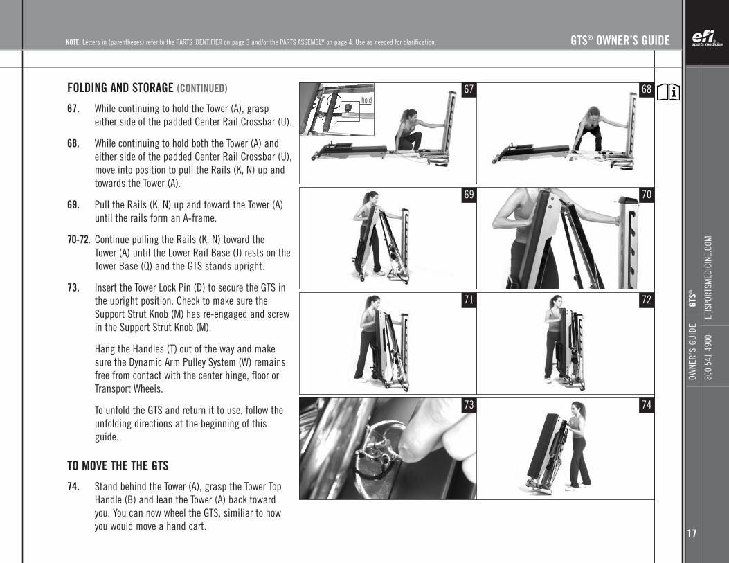
FOLDING AND STORAGE (CONTINUED)
67. While continuing to hold the Tower (A), graspeither side of the padded Center Rail Crossbar (U).
68. While continuing to hold both the Tower (A) andeither side of the padded Center Rail Crossbar (U),move into position to pull the Rails (K, N) up andtowards the Tower (A).
69. Pull the Rails (K, N) up and toward the Tower (A)until the rails form an A-frame.
70-72. Continue pulling the Rails (K, N) toward the Tower (A) until the Lower Rail Base (J) rests on theTower Base (Q) and the GTS stands upright.
73. Insert the Tower Lock Pin (D) to secure the GTS inthe upright position. Check to make sure theSupport Strut Knob (M) has re-engaged and screwin the Support Strut Knob (M).
Hang the Handles (T) out of the way and makesure the Dynamic Arm Pulley System (W) remainsfree from contact with the center hinge, floor orTransport Wheels.
To unfold the GTS and return it to use, follow theunfolding directions at the beginning of thisguide.
TO MOVE THE THE GTS
74. Stand behind the Tower (A), grasp the Tower TopHandle (B) and lean the Tower (A) back towardyou. You can now wheel the GTS, similiar to howyou would move a hand cart.
hold67
69
71
73
68
70
72
74
NOTE: Letters in (parentheses) refer to the PARTS IDENTIFIER on page 3 and/or the PARTS ASSEMBLY on page 4. Use as needed for clarification.

NOTE: Letters in (parentheses) refer to the PARTS IDENTIFIER on page 3 and/or the PARTS ASSEMBLY on page 4. Use as needed for clarification.
GETTING STARTED
Keep hands, fingers, hair, etc. away from all moving parts. Avoid touching hinges.
Participants using GTS should wear athletic shoes and comfortable lightweight clothing. Long hair should be tied back to avoid contact with the center pulley, center hinge or rollers. Before use, check toensure that all GTS parts are in place and working properly and the Support Strut Knob (M) is engaged.
Begin the exercise program at a level where participants can perform the exercise with good formthroughout the exercise set. As participants’ fitness level progress, raise the incline to increase the load and level of resistance. Build gradually to higher resistance levels, always keeping form and control. Avoid using momentum during cable exercises.
Remember to control the glideboard at all times, particularly when getting on or off the GTS. The following tips will help you stabilize the glideboard as you approach the unit for mounting in various positions.
PROPER FORWARD ANCHORING SEQUENCE WITH DYNAMIC ARM PULLEY SYSTEM (W)ATTACHED TO THE GLIDEBOARD (G)
75. Grasp both Handles (T) in the hand closest to the Tower (A) as you stand to one side of the GTS.
76. Pull the Glideboard (G) up the Rails (K,N) and sit in the proper position for the specific exercise you will perform. If you are performing a sitting exercise, sit at the top of the Glideboard (G).
77-78. If the exercise requires you to lie back, pull the Glideboard (G) up so you can sit at the bottom of theGlideboard (G) with one pulley Handle (T) in each hand.
75
76
77
78

OWNE
R’S
GUID
EGT
S®
800
541
4900
EFIS
PORT
SMED
ICIN
E.CO
M
19
GTS® OWNER’S GUIDE
OWNE
R’S
GUID
EGT
S®
800
541
4900
EFIS
PORT
SMED
ICIN
E.CO
M
19
79. When lying on your back, be sure your head is supported on the Glideboard (G). Securely tie-uplong hair to avoid getting caught in moving parts. If the Glideboard (G) travels all the way tothe top or bottom of its rolling distance during the exercise, adjust your body up or down on theGlideboard (G).
PROPER BACKWARD ANCHORING SEQUENCE WITH DYNAMIC ARM PULLEY SYSTEM (W)ATTACHED TO GLIDEBOARD (G)
80. Grasp Handles (T), then make a fist and place your knuckles at the top of the Glideboard (G)to anchor it in place. Now it is safe to sit, straddle or kneel on the Glideboard (G).
81. When kneeling on the Glideboard (G), place knees one at a time just behind your fists as you face the Glideboard (G).
82. Move to the starting position of the exercise and begin by using controlled movements.
Always control the Glideboard (G) while mounting or dismounting your GTS.Do not exceed 650 pounds (295 kg) of weight-bearing on GTS.
WARNING!
79
80
81
82
NOTE: Letters in (parentheses) refer to the PARTS IDENTIFIER on page 3 and/or the PARTS ASSEMBLY on page 4. Use as needed for clarification.

NOTE: Letters in (parentheses) refer to the PARTS IDENTIFIER on page 3 and/or the PARTS ASSEMBLY on page 4. Use as needed for clarification.
MAINTENANCE AND CARE
Your GTS will offer your health and fitness orwellness facility and your clientele years of easyoperation if you follow these simple tips formaintenance and care. With periodic cleaning,moving parts and rolling surfaces will maintaintheir smooth function.
Daily
• Wipe down padded surfaces with antibacterial cleanser after each use.
• Move Glideboard (G) up and down Rails (K,N)to ensure smooth tracking. If Glideboard (G)does not roll smoothly, clean Rails (K, N) androllers/wheels thoroughly with DRY cloth.
• Ensure that Support Strut Knob (M) is securebefore use (tighten clockwise).
• Ensure that the Tower Crossbar (Z) is securelyseated into Tower Level Hooks (R) after eachlevel change.
Weekly
• Inspect Dynamic Arm Pulley System (W) forwear or damage. If plastic outer cable coveris compromised in any way, replace damagedcable.
• Wipe down rails with dry cloth and use chromepolish when necessary to remove dust buildup.
• Clean and dry all surface areas for aesthetics.
• Check all Screws,Fasteners and Knobs toensure that they are installed correctly andtightened.
a. LAT Bars screws
b. Folding Foot Holder (E) screws
c. Pull Pins/Retractable Knobs
d. Glideboard Wheel Housings (L) on the Glideboard (G)
e. Shoulder Bolt on the Rail Center Hinge
• Check for ease of use when changing levels on the GTS Tower (A). Report any difficulty inchanging levels or seating the Tower Crossbar (Z)in the Tower Level Hooks (R). Discontinue use ifcustomers cannot seat the Rails (K, N) properlyand contact efi Sports Medicine AccountCoordinator. Check the looseness of theRectangular Bushings (V) by holding the TowerCrossbar (Z) above the Level 7 hook. Push theTower (A) back and release. If the Tower (A)does not rock forward by itself, check thetightness of the nyloc nuts on the TowerCrossbar (Z) or contact efi Sports Medicine.
• Visually and functionally check all pulleys forsmooth operation. Clean as needed.
• Check all pads, fabric or foam for wear andreplace as needed.
a. Folding Foot Holder (E) pads
b. Glideboard (G) upholstery
c. Counter Weight Strap in Tower (A)
d. Handles (T)
Monthly
• Remove all Glideboards (G) for visualinspection of rollers/wheels. Clean any debrisaccumulated on the roller assembly.
• Ensure that the rubber stoppers located on theCenter Rail Crossbar (U) are tight. Replacedamaged stoppers.
• Inspect and clean rubber pads located beneaththe tower base to ensure good “gripping” onwood floors.
• Visually inspect all double leg pulley assemblykits to ensure they are secure and tightened onthe Tower (A). (This is an optional accessory).Tighten and secure as necessary.
• Check function of the Support Strut Knob (M). For safety, secure all Support Strut Knobs (M)clockwise before use.
• Visually inspect all Glideboards (G) for tearingor punctures.
• Check all additional accessories for properfunction and wear.
• For long-term storage or high humidityenvironments, WD40 can be applied to a clothand wiped lightly to all chrome surfaces. Wipedry before use.

GTS® OWNER’S GUIDE
OWNE
R’S
GUID
EGT
S®
800
541
4900
EFIS
PORT
SMED
ICIN
E.CO
M
21
NOTE: Letters in (parentheses) refer to the PARTS IDENTIFIER on page 3 and/or the PARTS ASSEMBLY on page 4. Use as needed for clarification.
Directive prEN-957-1, EN-957- 2, EN-957-7
Class S
SAFETY COMPLIANCES WARNING:The GTS should only be used in a supervised area whereaccess and control is specifically regulated by theowner. The extent of control depends on the user e.g.degree of reliability, age, experience, etc.
SAFETY PRECAUTIONS
WARNING: Failure to read and follow the safetyinstructions in this Owner’s Guide may result inserious injury or death. Hazards include but arenot limited to falling, overexertion, strainedmuscles, pinched fingers or pulled hair.
KEEP HANDS, FINGERS AND HAIR AWAY FROMALL MOVING PARTS. AVOID TOUCHING HINGES.
Before starting this or any exercise program,the participant should consult his or herphysician, who can assist in planning aprogram for the individual’s age and physicalcondition. Certain exercise programs or types of equipment may not be appropriate for all people.
Do not over exert with this or any exerciseprogram. If any pain or tightness in the chestis experienced, or an irregular heartbeat,shortness of breath, or faintness, nausea ordizziness, stop exercising immediately andconsult your physician before resuming anyexercise program. (Clinicians should followthese recommendations if these symptomsare observed in patients.)
This product is designed and intended forcommercial use. Use only as instructed. Do notleave anyone unattended on the GTS. Do notpermit anyone to stand on your GTS or use it asfurniture. Children should only use GTS whenclosely attended and supervised by an adult.
Appropriate exercise attire should be worn.
Inspect your GTS before each use to ensureproper operation. Do not use your GTS if it isnot completely assembled or has beendamaged in any manner. All parts should bechecked for wear before each use. Cables andhandle webbing showing signs of wear shouldbe replaced immediately. Contact efi SportsMedicine Customer Service for replacementparts or repairs.
Use only accessory items recommended by themanufacturer. Only use accessories in themanner specified by the manufacturer.
Make sure participants take care getting onand off the unit. Falling on or off could resultin severe or fatal injury.
Place your GTS on a flat solid surface withnonskid material underneath.
Follow the instructions that are outlined in this Owner’s Guide for operating your GTS.
RESISTANCE CHARTS (SEE NEXT PAGE)
How GTS works:GTS uses a variable angle incline plane tocreate exercise resistance by modifying theuser’s body weight–the steeper the angle, themore resistance. To determine amount ofresistance being used during an exercise,simply multiply the user’s body weight by theappropriate percentage indicated in the chart.The result of this calculation is the resistance(force) in pounds or kilograms required to movethe glideboard. When figuring exercises thatincorporate the pulley cables, use 50% of thecharted numbers. Note: Chart is accuratewithin a 4% margin of error.
Example:A 200 lb person using level 3 would be lifting44 lbs. or 22% of total body weight. A 95 kg person using level 3 would be lifting21 kg. or 22% of total body weight.
Product GTS: GRAVITY TRAINING SYSTEM

NOTE: Letters in (parentheses) refer to the PARTS IDENTIFIER on page 3 and/or the PARTS ASSEMBLY on page 4. Use as needed for clarification.
RESISTANCE CHARTS

©20
06,e
fiCo
rp.
GTS® PURCHASE RECORD
Date Purchased ______________________________________________________________________
Purchased From __________________________________________________________________
Model Number ________________________________________________________________________
Serial Number ________________________________________________________________________
_______________________________________________________________________________
_______________________________________________________________________________
_______________________________________________________________________________
_______________________________________________________________________________
_______________________________________________________________________________
_______________________________________________________________________________
_______________________________________________________________________________
_______________________________________________________________________________
_______________________________________________________________________________
_______________________________________________________________________________
_______________________________________________________________________________
_______________________________________________________________________________
_______________________________________________________________________________
_______________________________________________________________________________
_______________________________________________________________________________
________________________________________________________________________________
______________________________________________________________________________
_______________________________________________________________________________
Retain this form for your records.
WARRANTY CLAIMSefi Sports Medicine treats warranty claims asa priority. To process these quickly, a ReturnMerchandise Authorization (RMA) number is requiredto properly link your merchandise with your claim.efi Sports Medicine does not accept returned merchandise without an accompanying RMA number.Contact efi Sports Medicine Customer ServiceDepartment at 800-541-4900 if you are makinga warranty claim. A representative will issue you anRMA number and instructions for proper packaging of the equipment for shipping.
IMPORTANT! - Save your invoice. Please retainpackaging instructions.
Shipping Damage: FOB origin, unless otherwisespecified. efi Sports Medicine accepts no responsibility for damage in shipping.
efi Sports Medicine does, however, make every effortto facilitate the satisfactory resolution of claimsmade against delivery agents for damage duringshipping.
If the GTS appears to have sustained damage inshipping, or if the GTS appears to have shifted indelivery but no damage is evident, retain the shipping boxes until the GTS has been fully assembled to assure there is no functional damagethat is not initially visible. In the event of damageduring shipping, retaining the shipping boxes helpsto facilitate your claim against the shipper.
Take photographs of damaged boxes or contentsbefore opening.
GTS® OWNER’S GUIDE
23
OWNE
R’S
GUID
EGT
S®
800
541
4900
EFIS
PORT
SMED
ICIN
E.CO
M

©20
03,e
fiCo
rpor
atio
n.
efi Sports Medicine7755 Arjons DriveSan Diego, CA 92126
efisportsmedicine.com
©2003/2007, efi Corp./99218. All rights reserved.Manufactured in Taiwan and sold under USA Design Patent No. 6,921,355. Also covered by one or more of the following patents: D493,853; D405,132; 4,004,801; 5,169,363; 5,967,955.
LIMITED WARRANTY GTS®
Subject to the exclusions and other terms and conditions set forth below, Engineering Fitness International Corp.(“EFI”) warrants the following components to be free from defects in materials and workmanship under normalusage for the period(s) specified below. This limited warranty is your exclusive remedy and applies to new productspurchased in the United States, which are accompanied by this written warranty.
EFI, at its option, will repair, replace or refund the purchase price of any product that does not conform to this warranty. Repairs or replacement will be made at no charge to the customer for parts or labor, provided that thecustomer shall be responsible for any transportation and shipping costs. EFI may use functionally equivalent reconditioned/refurbished/pre-owned or new products, accessories and parts.
This warranty is valid only for the original purchaser, and proof of purchase will be required. This warranty will bevalid only if the Ownership Registration Certificate is completed and received by EFI no later than 30 days after thedate of purchase. This warranty extends only to the first purchaser, and is not transferable.
Warranties outside the United States may vary. Ask for details.
Exclusions from CoverageNormal Wear and Tear. Periodic maintenance, repair and replacement of parts due to normal wear and tear areexcluded from coverage.
Ornamental Decorations. Ornamental decorations such as emblems, graphics and other decorative elements, areexcluded from coverage.
Abuse and Misuse. Defects or damage that result from improper operation, storage, misuse or abuse, accident orneglect, subjecting the product to abnormal usage or conditions or other acts which are not the fault of EFI areexcluded from coverage. Use of the product in any manner that is inconsistent with the instructions provided by EFI is considered misuse and any defects or damage that result from such misuse are excluded from coverage. (contined on reverse side...)
To register for ownership, complete form on reverse side and return by mail, in envelope, to:
efi Sports Medicine7755 Arjons DriveSan Diego, CA 92126
If you have any questions about your model or if you need service, please contact Customer Service at 800 541 4900.
TEAR AT PERFORATION.
TEAR
ATPE
RFOR
ATIO
N.

OWNERSHIP REGISTRATION CERTIFICATE
Purchase Date _____/_____/_____ Product Name ________________________________________________
Purchaser’s Name (print) ______________________________________________________________________________________
Address ________________________________________________________________________________
City ________________________________________________ State ________________ Zip_________
Phone _____________________ Email Address ______________________________________________
SERIAL NUMBER(S) ____________________________________________________________________
Signature ____________________________________________________________________________
Complete this form and return by mail, in envelope, to register ownership.
NON-COMMERCIAL WARRANTY:Frame: Limited Lifetime (excluding coatings)
Wear items: 2 years (includes moving parts and items not listed)
Foam, rubber, upholstery, straps and webbing:6 months
COMMERCIAL WARRANTY:Frame: 5 years (excluding coatings)
Wear items: 1 year (includes moving parts and items not listed)
Foam, rubber, upholstery, straps and webbing:90 days
LIMITED WARRANTY GTS® (...contined from reverse side)[Commercial Use. Defects or damage that result from use of the product for commercial purposes are excludedfrom coverage.]
Use of Non-EFI Accessories. Defects or damage that result from the use of Non-EFI branded or certified accessories are excluded from coverage.
Unauthorized Service or Modification. Defects or damages that result from service, maintenance, repairs, adjustment, installation or alteration conducted by anyone other than EFI or its authorized representatives areexcluded from coverage.
Limitation of LiabilityTHE WARRANTIES AND REMEDIES CONTAINED HEREIN ARE EXCLUSIVE AND IN LIEU OF ALL OTHER WARRANTIES,WHETHER EXPRESS, IMPLIED OR STATUTORY, INCLUDING ANY LIABILITY ARISING UNDER ANY WARRANTY OF MERCHANTABILITY OR FITNESS FOR A PARTICULAR PURPOSE, STATUTORY OR OTHERWISE.
IN NO EVENT SHALL EFI BE LIABLE FOR ANY INCIDENTAL, SPECIAL, INDIRECT OR CONSEQUENTIAL DAMAGES,WHETHER RESULTING FROM THE USE, MISUSE OR INABILITY TO USE THE PRODUCT OR FROM DEFECTS IN THEPRODUCT.
EFI retains the exclusive right to repair or replace the product or offer a full refund of the purchase price at itssole discretion. SUCH REMEDY SHALL BE YOUR SOLE AND EXCLUSIVE REMEDY FOR ANY BREACH OF WARRANTY.
TEAR AT PERFORATION.
TEARAT
PERFORA TION.