owner’s guide and installation manual - montecarlofans.com€¦ · owner’s guide and...
TRANSCRIPT
Owner’s Guide and Installation Manual
Attach sales receipt to this card and retain as your proof of purchase
DATE OF PURCHASE:
MODEL NUMBER:
RETAILER NAME:
RETAILER ADDRESS:
To register your fixture, please visit our website www.montecarlofans.com
3MO52XXO-L / 3MTR38XXO-L Series Fans
Total fan weight with light kit
UL Model Number of 3MO52XXO-L: 52HHUL Model Number of 3MTR38XXO-L: 38HH

© 2011 Monte Carlo Fan Company 5/25/20132
WARNING: TO REDUCE THE RISK OF FIRE, ELECTRIC SHOCK, OR INJURY TO PERSONS, OBSERVE THE FOLLOWINGREAD AND SAVE THESE INSTRUCTIONS
Installation work and electrical wiring must be done by qualified person(s) in accordance with applicable codes and standards (ANSI/NFPA 70-1999), includingfire-rated construction.
Use this unit only in the manner intended by the manufacturer. If you have any questions contact the manufacturer.
After making the wire connections, the wires should be spread apart with the grounded conductor and the equipment-grounding conductor on one side of theoutlet box and ungrounded conductor on the other side of the outlet box. The splices, after being made, should be turned upward and pushed carefully upinto the outlet box.
WARNING: Before you begin installing the fan, servicing or cleaning unit, Switch power off at Service panel and lock service disconnecting means to preventpower from being switched on accidentally. When the service disconnecting means cannot be locked, securely fasten a prominent warning device, such as atag, to the service panel.
Be cautious! Read all instructions and safety information before installing your new fan. Review the accompanying assembly diagrams.
When cutting or drilling into wall or ceiling, do not damage electrical wiring and other hidden utilities.
Make sure the installation site you choose allows the fan blades to rotate without any obstructions. Allow a minimum clearance of 7 feet from the floor to thetrailing edge of the blade.
WARNING: To Reduce The Risk Of Fire, Electric Shock, or Personal Injury, Mount To Outlet Box Marked “Acceptable for Fan Support of15.9 kg (35 lbs) or less” And Use Mounting Screws Provided With The Outlet Box.
CAUTION: For Compliance with Local Codes and Regulations, If Installing The Secondary Support Safety Cable in the U.S., Do Not Re-move Knockouts In The Outlet Box. Mount the secondary support safety cable through the reserved nail/screw hole on the outlet box tothe building structure (or the ceiling joist).
WARNING: To reduce the risk of personal injury, do not bend blade holders during installation to motor, balancing or during cleaning. Do not insert foreignobject between rotating blades.
Attach the mounting bracket using only the hardware supplied with the outlet box.
WARNING: To reduce the risk of fire or electric shock, this fan must be installed with an isolating wall control/switch.
WARNING: To reduce the risk of fire or electric shock, this fan should only be used with fan speed control part no. UC7067RC manufactured by Rhine Elec-tronic Co., Ltd.
If this unit is to be installed over a tub or shower, it must be marked as appropriate for the application.
Never place a switch where it can be reached from a tub or shower.
The combustion airflow needed for safe operation of fuel-burning equipment may be affected by this unit’s operation. Follow the heating equipment manufac-turer’s guideline safety standards such as those published by the National Fire Protection Association (NFPA), and the American Society for Heating, Refrigera-tion and Air Conditioning Engineers (ASHRAE) and the local code authorities.
CAUTION: To Reduce the Risk of Electric Shock, Disconnect the electrical supply circuit to the fan before installing the light kit.
All set screws must be checked and tightened where necessary before installation.
Customer Service800-969-3347
Customer Service Center7400 Linder Ave.Skokie, IL 60077
www.montecarlofans.com
Tools Required for Assembly (not included): Electrical Tape, Phillips Screwdriver, Pliers, Safety Glasses,Stepladder and Wire Strippers.
© 2011 Monte Carlo Fan Company 5/25/20133
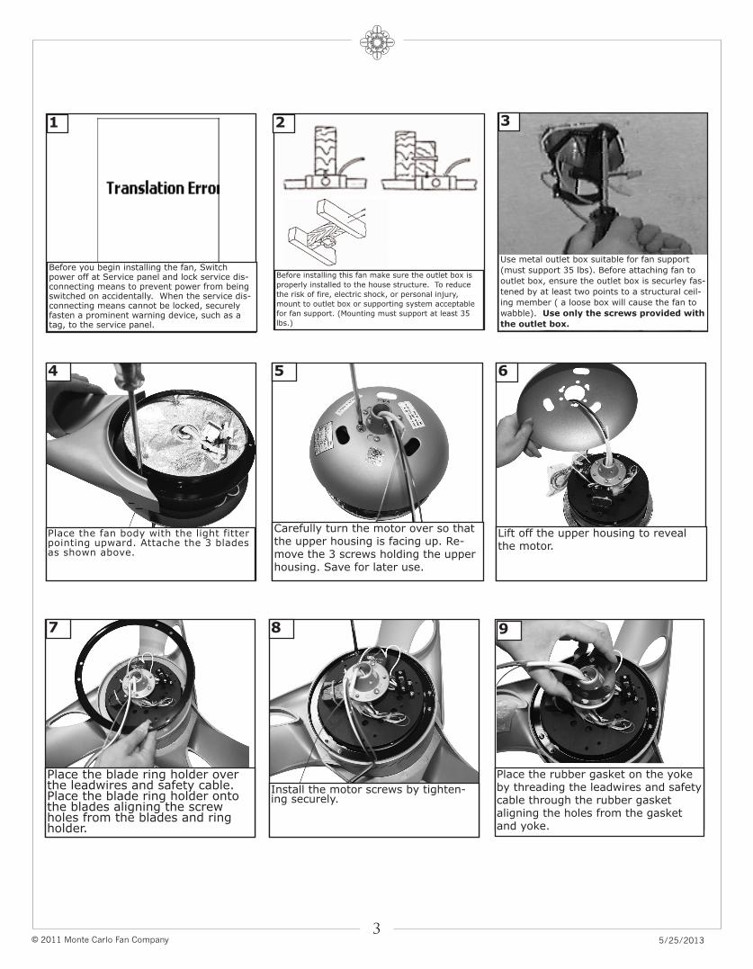
Before you begin installing the fan, Switchpower off at Service panel and lock service dis-connecting means to prevent power from beingswitched on accidentally. When the service dis-connecting means cannot be locked, securelyfasten a prominent warning device, such as atag, to the service panel.
Before installing this fan make sure the outlet box is
properly installed to the house structure. To reduce
the risk of fire, electric shock, or personal injury,
mount to outlet box or supporting system acceptable
for fan support. (Mounting must support at least 35
lbs.)
Use metal outlet box suitable for fan support
(must support 35 lbs). Before attaching fan to
outlet box, ensure the outlet box is securley fas-
tened by at least two points to a structural ceil-
ing member ( a loose box will cause the fan to
wabble). Use only the screws provided with
the outlet box.
321
Carefully turn the motor over so thatthe upper housing is facing up. Re-move the 3 screws holding the upperhousing. Save for later use.
5
Lift off the upper housing to revealthe motor.
6
Place the fan body with the light fitterpointing upward. Attache the 3 bladesas shown above.
4
Place the blade ring holder overthe leadwires and safety cable.Place the blade ring holder ontothe blades aligning the screwholes from the blades and ringholder.
7
Install the motor screws by tighten-ing securely.
8
Place the rubber gasket on the yokeby threading the leadwires and safetycable through the rubber gasketaligning the holes from the gasketand yoke.
9
© 2011 Monte Carlo Fan Company 5/25/20134
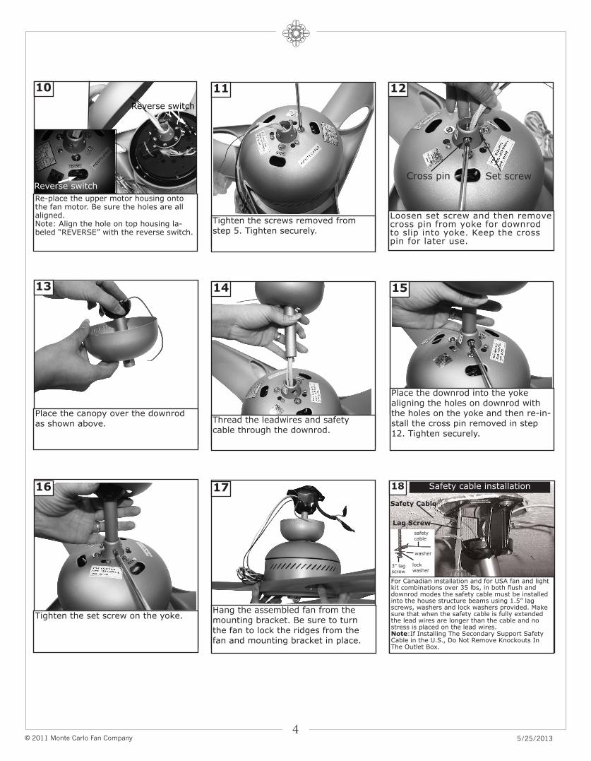
Loosen set screw and then removecross pin from yoke for downrodto slip into yoke. Keep the crosspin for later use.
12
Re-place the upper motor housing ontothe fan motor. Be sure the holes are allaligned.Note: Align the hole on top housing la-beled “REVERSE” with the reverse switch.
10
Tighten the screws removed fromstep 5. Tighten securely.
11
Place the canopy over the downrodas shown above.
13
Thread the leadwires and safetycable through the downrod.
14
Place the downrod into the yokealigning the holes on downrod withthe holes on the yoke and then re-in-stall the cross pin removed in step12. Tighten securely.
15
Tighten the set screw on the yoke.
16
Hang the assembled fan from themounting bracket. Be sure to turnthe fan to lock the ridges from thefan and mounting bracket in place.
17
Set screwCross pinReverse switch
Reverse switch
For Canadian installation and for USA fan and lightkit combinations over 35 lbs, in both flush anddownrod modes the safety cable must be installedinto the house structure beams using 1.5” lagscrews, washers and lock washers provided. Makesure that when the safety cable is fully extendedthe lead wires are longer than the cable and nostress is placed on the lead wires.Note:If Installing The Secondary Support SafetyCable in the U.S., Do Not Remove Knockouts InThe Outlet Box.
18 Safety cable installation
Safety Cable
Lag Screw
safetycable
3” lagscrew
lockwasher
washer
© 2011 Monte Carlo Fan Company 5/25/20135
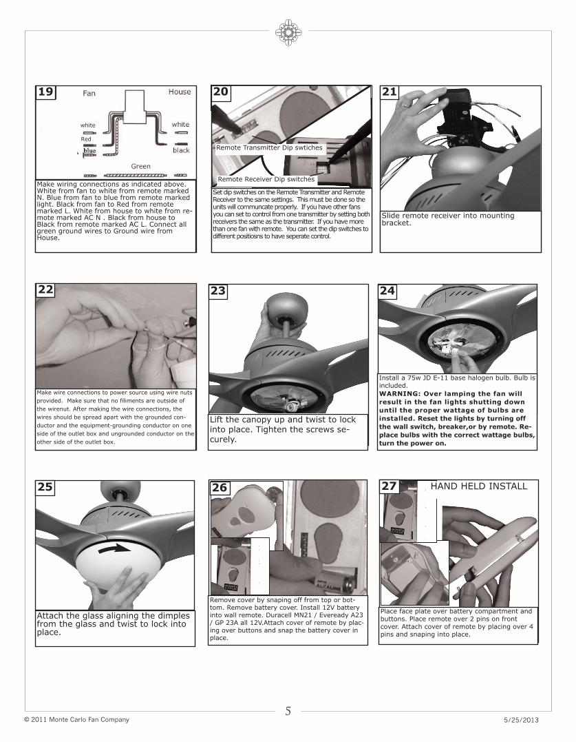
Lift the canopy up and twist to lockinto place. Tighten the screws se-curely.
23
Install a 75w JD E-11 base halogen bulb. Bulb isincluded.
WARNING: Over lamping the fan will
result in the fan lights shutting down
until the proper wattage of bulbs are
installed. Reset the lights by turning off
the wall switch, breaker,or by remote. Re-
place bulbs with the correct wattage bulbs,
turn the power on.
24
Slide remote receiver into mountingbracket.
21
Make wiring connections as indicated above.White from fan to white from remote markedN. Blue from fan to blue from remote markedlight. Black from fan to Red from remotemarked L. White from house to white from re-mote marked AC N . Black from house toBlack from remote marked AC L. Connect allgreen ground wires to Ground wire fromHouse.
19
white
Red
Set dip switches on the Remote Transmitter and RemoteReceiver to the same settings. This must be done so theunits will communcate properly. If you have other fansyou can set to control from one transmitter by setting bothreceivers the same as the transmitter. If you have morethan one fan with remote. You can set the dip switches todifferent positiosns to have seperate control.
Remote Transmitter Dip swtiches
Remote Receiver Dip switches
20
Make wire connections to power source using wire nuts
provided. Make sure that no filiments are outside of
the wirenut. After making the wire connections, the
wires should be spread apart with the grounded con-
ductor and the equipment-grounding conductor on one
side of the outlet box and ungrounded conductor on the
other side of the outlet box.
22
Attach the glass aligning the dimplesfrom the glass and twist to lock intoplace.
25
Remove cover by snaping off from top or bot-tom. Remove battery cover. Install 12V batteryinto wall remote. Duracell MN21 / Eveready A23/ GP 23A all 12V.Attach cover of remote by plac-ing over buttons and snap the battery cover inplace.
Place face plate over battery compartment andbuttons. Place remote over 2 pins on frontcover. Attach cover of remote by placing over 4pins and snaping into place.
2726 HAND HELD INSTALL
© 2011 Monte Carlo Fan Company 5/25/20136
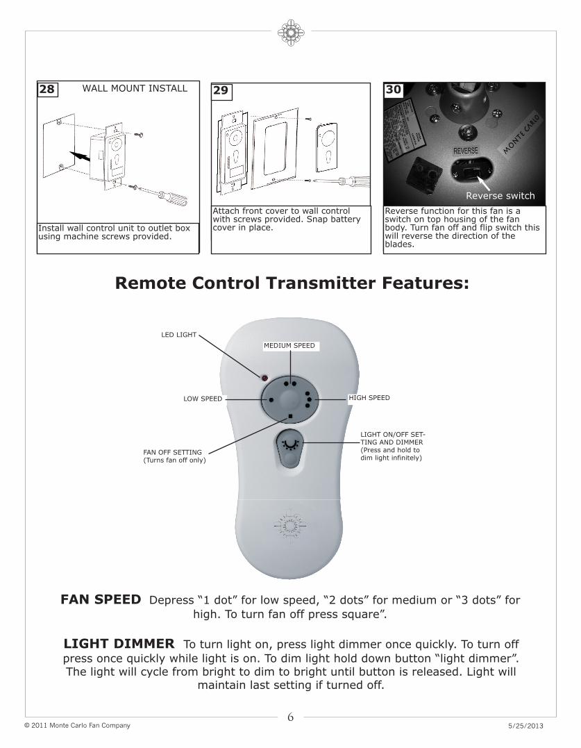
Reverse function for this fan is aswitch on top housing of the fanbody. Turn fan off and flip switch thiswill reverse the direction of theblades.
30
Install wall control unit to outlet boxusing machine screws provided.
28
Attach front cover to wall controlwith screws provided. Snap batterycover in place.
29WALL MOUNT INSTALL
Reverse switch
Remote Control Transmitter Features:
FAN SPEED Depress “1 dot” for low speed, “2 dots” for medium or “3 dots” for
high. To turn fan off press square”.
LIGHT DIMMER To turn light on, press light dimmer once quickly. To turn off
press once quickly while light is on. To dim light hold down button “light dimmer”.The light will cycle from bright to dim to bright until button is released. Light will
maintain last setting if turned off.
HIGH SPEED
MEDIUM SPEED
LOW SPEED
FAN OFF SETTING(Turns fan off only)
LIGHT ON/OFF SET-TING AND DIMMER(Press and hold todim light infinitely)
LED LIGHT
© 2011 Monte Carlo Fan Company 5/25/20137
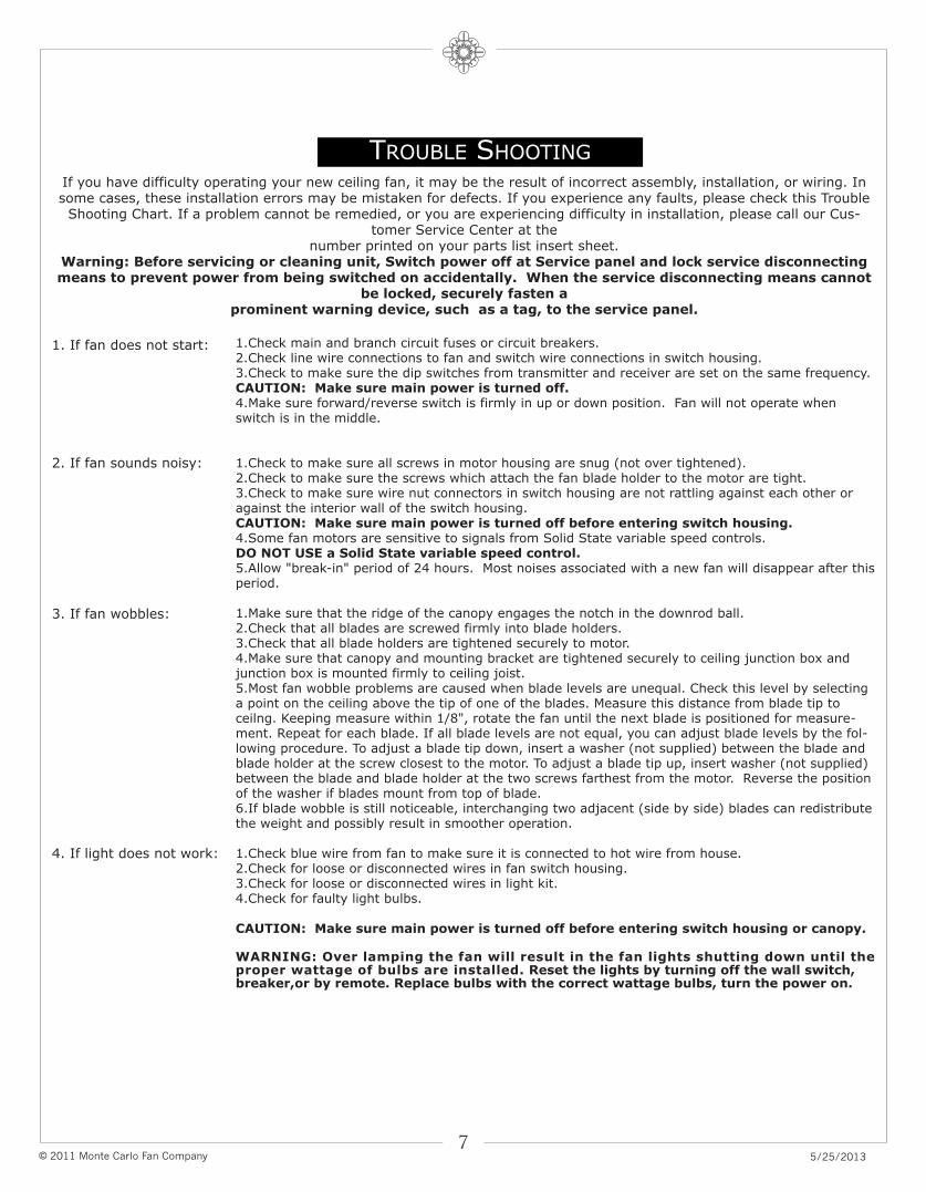
1.Check main and branch circuit fuses or circuit breakers.2.Check line wire connections to fan and switch wire connections in switch housing.3.Check to make sure the dip switches from transmitter and receiver are set on the same frequency.CAUTION: Make sure main power is turned off.4.Make sure forward/reverse switch is firmly in up or down position. Fan will not operate whenswitch is in the middle.
1.Check to make sure all screws in motor housing are snug (not over tightened).2.Check to make sure the screws which attach the fan blade holder to the motor are tight.3.Check to make sure wire nut connectors in switch housing are not rattling against each other oragainst the interior wall of the switch housing.CAUTION: Make sure main power is turned off before entering switch housing.4.Some fan motors are sensitive to signals from Solid State variable speed controls. DO NOT USE a Solid State variable speed control.5.Allow "break-in" period of 24 hours. Most noises associated with a new fan will disappear after thisperiod.
1.Make sure that the ridge of the canopy engages the notch in the downrod ball.2.Check that all blades are screwed firmly into blade holders.3.Check that all blade holders are tightened securely to motor.4.Make sure that canopy and mounting bracket are tightened securely to ceiling junction box andjunction box is mounted firmly to ceiling joist.5.Most fan wobble problems are caused when blade levels are unequal. Check this level by selectinga point on the ceiling above the tip of one of the blades. Measure this distance from blade tip toceilng. Keeping measure within 1/8", rotate the fan until the next blade is positioned for measure-ment. Repeat for each blade. If all blade levels are not equal, you can adjust blade levels by the fol-lowing procedure. To adjust a blade tip down, insert a washer (not supplied) between the blade andblade holder at the screw closest to the motor. To adjust a blade tip up, insert washer (not supplied)between the blade and blade holder at the two screws farthest from the motor. Reverse the positionof the washer if blades mount from top of blade.6.If blade wobble is still noticeable, interchanging two adjacent (side by side) blades can redistributethe weight and possibly result in smoother operation.
1.Check blue wire from fan to make sure it is connected to hot wire from house.2.Check for loose or disconnected wires in fan switch housing.3.Check for loose or disconnected wires in light kit.4.Check for faulty light bulbs.
CAUTION: Make sure main power is turned off before entering switch housing or canopy.
WARNING: Over lamping the fan will result in the fan lights shutting down until theproper wattage of bulbs are installed. Reset the lights by turning off the wall switch,breaker,or by remote. Replace bulbs with the correct wattage bulbs, turn the power on.
2. If fan sounds noisy:
1. If fan does not start:
3. If fan wobbles:
4. If light does not work:
TROUBLE SHOOTING
If you have difficulty operating your new ceiling fan, it may be the result of incorrect assembly, installation, or wiring. Insome cases, these installation errors may be mistaken for defects. If you experience any faults, please check this Trouble
Shooting Chart. If a problem cannot be remedied, or you are experiencing difficulty in installation, please call our Cus-tomer Service Center at the
number printed on your parts list insert sheet. Warning: Before servicing or cleaning unit, Switch power off at Service panel and lock service disconnectingmeans to prevent power from being switched on accidentally. When the service disconnecting means cannot
be locked, securely fasten a prominent warning device, such as a tag, to the service panel.
Dec.2011 new format
Jan.2011 Update customer service phone number
May.2013 Update for CUL regulation