owner’s guide - phoenixmanufacturing.com · 09/11/17 1-999-1539 rev a owner’s guide use and...
TRANSCRIPT

1-999-1539 REV A09/11/17
Owner’s Guide Use and Care Manual
Customer Service 1-800-325-6952
• Safety • Installation • Start-up
• Operation • Maintenance • Troubleshooting
Ducted Cooler Models: FD350, FD450, FD650 FS350, FS450, FS650
Congratulations: You have purchased a product of superior performance and design, which will give the best service when properly installed, operated and maintained.
• Read all instructions carefully before installation.• Cooler motor, pump, cabinet and junction box must be
grounded in accordance with all local and national codes. A ground wire must be used between the cooler and the power source.
• Always disconnect electrical power to the cooler before working on cooler.
• WARNING To reduce the risk of fire or electrical shock do NOT use this fan with any solid state speed control device.
• Do NOT remove side panels while cooler is running.• Do NOT operate with evaporative pad removed.• Do NOT locate cooler near exhaust or vent pipes as
odors or fumes may be drawn into the unit.• Be sure cooler is connected to proper line voltage
stamped on blower motor and pump motor specification plate. NOTE: IMPROPER VOLTAGE WILL VOID MOTOR WARRANTY.
READ AND SAVE THESE IMPORTANT SAFETY INSTRUCTIONS
WARNING - TO REDUCE THE RISK OF FIRE, ELECTRICAL SHOCK, OR INJURY TO PERSONS, OBSERVE THE FOLLOWING:
This guide will provide you with information needed to assemble the unit. It also contains information on how to safely operate, inspect, maintain and troubleshoot your Frigiking evaporative air cooler.
THE USE OF ANODE DEVICES, CHEMICAL ADDITIVES, OR COOLER CLEANER TREATMENTS IN THIS COOLER WILL VOID THE WARRANTY.
Model # Serial #
Date of Purchase:
Place of Purchase:
Serial # can be found outside the cabinet.
• Your warranty does NOT cover shipping damage. Report all shipping damage at once to store making the delivery.
• For future reference, record the model and serial number, date and place of purchase of your evaporative cooler here:

INSTALLATIONInstallation requires connection of blower opening to existing air ducting system or to a dropper duct with a ceiling diffuser. In either instance, building modification is necessitated. The bottom discharge cooler is always mounted on the roof of the structure. This will require a roof stand, roof jack, flexible duct and collar to connect to existing ductwork. If installation is being made by other than a professional HVAC contractor, it is suggested that the installation be throughly discussed with a professional sales person familiar with cooler installation and that printed instructions be requested for the installation equipment and supplies purchased.
DO NOT DRIVE NAILS OR SCREWS INTO BOTTOM OF COOLER, THIS WILL CAUSE IT TO LEAK WATER AND WILL VOID THE WARRANTY.
* FOR MOBILE HOME INSTALLATION SEE SEPARATE INSTRUCTION SHEET IN GRILL KIT BOX.
Whenever the cooler is mounted, the surface must be level. This is necessary so that the water in the reservoir and in the troughs of the pad frame will be level when the cooler is operating.
Page 2
TYPICAL SIDE DISCHARGE
TYPICAL DOWN DISCHARGE
WATER CONNECTION Continued2. Turn water to cooler on and set float valve to maintain 2 1/2" water depth.
The float valve is adusted by bending the float valve rod.3. Bleed-off: Bleed off is helpful to prevent scale from building up in the
cooler. A bleed-off adapter tee and tube are furnished with the cooler for this purpose. Run bleed-off line to a proper drain.
Note: Evaporative coolers should not be connected to a "soft" water system.
DRAIN BUSHINGInsert drain bushing through the hole in the cooler bottom pan. Attach nut securely and hand tighten. Do NOT use a wrench.
WALL SWITCH: For one or two speed (120 ro 240 volt) use switch kit available from your dealer.
ADJUSTABLE MOTOR PULLEY (SHEAVE): This part is set at the factory for proper motor load and maximum air delivery of a cooler not connected duct and register system. When cooler is connected to a duct system the cooler air capacity and motor amperage decrease due to static pressure (duct resistance). The adjustable motor pulley is used ONLY to compensate for duct system resistance by returning cooler and motor to proper load capacity and should not be adjusted except for that purpose.
CAUTION: AMPERAGE OF MOTOR MUST BE CHECKED TO MAKE CERTAIN IT DOES NOT EXCEED THE MAXIMUM ALLOWED AS STAMPED ON MOTOR SPECIFICATION PLATE.
Only persons with proper electrical equipment and thorough knowledge of adjustable pulleys should attempt adjustment of your cooler.
WARNING: IMPROPER PULLEY ADJUSTMENT CAN OVERLOAD AND BURN OUT MOTOR AND VOID WARRANTY.
ROOF
DUCT
CEILING
WOOD OR ANGLE IRON SUPPORT
DUCT
COOLER
ROOF JACK
COOLER STAND
*COLLAR (with flange)
*FLEX DUCT
WATER CONNECTION1. Install float in hole provided in float bracket. See parts illustration to route
water line. Connect per above sketch.
MOTOR KITS
INSTALLATION1. Install the motor in the mounting cradle as shown.2. Remove the junction box from the cooler.3. Wire the pump and motor receptacles per the schematic shown below.4. Place both receptacles in the junction box as shown and re-attach the
junction box to the cooler top.
120 VOLT MOTOR KIT

Page 3
The orange wire is not used. Double it over and cover the bare end with electrical tape.
A
INSTALLATION1. Install the motor in the mounting cradle as shown.2. Remove the junction box from the cooler.3. Remove 120 volt pump and pump receptacle furnished with cooler and
replace it with the 240 volt LSP-94 pump and pump receptacle. (see replacement parts list)
4. Wire the pump and motor receptacles per the schematic shown above.5. Place both receptacles in the junction box as shown and re-attach the
junction box to the cooler top.
240 VOLT MOTOR KIT
The white wire is not used. Double it over and cover the bare end with electrical tape or wirenut.
A
A
B
Green
Black White
15A 120V
5 P
in
MotorRecp.
Red
Black
White
Green
OrangeGND
Green
White
Black
Red
Pump
Black
Green
White
Lo
Hi
Com
PowerSupply
3 P
in
Green
Black White
15A 120V
BlackGreen
White3
Pin
Pump
Black
Red
White
Green
Lo
HiComRed
BlackWhiteGreenOrange
5 P
in
A
Motor Recp.
GND
A
Green
Black Orange
15A 230V
5 P
in
MotorRecp.
Red
Black
Orange
Green
WhiteGND
Green
Orange
Black
Red
Pump
Black
Green
Orange
Lo
Hi
Com
PowerSupply
3 P
in
B
Green
Black Orange
15A 230V
Black
Green
Orange3 P
in
Pump
Black
Red
Orange
Green
LoHi
ComRed
BlackOrange
GreenWhite
5 P
in
A
Motor Recp.
GND
Power Supply
Power Supply
120 VOLT MOTOR KIT
BLOWER BELT ADJUSTMENTCorrect belt tension adjustment is important. Incorrect adjustment increases power consumption and shortens belt and motor life.
Install belt over motor and blower pulleys. (A) check belt tension by squeezing (deflecting) belt. Proper tension will allow deflection of 1/2 to 3/4 inch. (B) To increase or decrease belt tension, loosen bolt in slot of motor support brcket. Adjust belt to desired tension and re-tighten bolt.
OPERATION
PRE-WET PADSFor maximum cooling efficiency, prior to the initial start up of the cooler remove the pad frame assemblies from the cooler and spray the pad and frames thoroughly with water from a garden hose.
Put the pad frame assemblies back on the cooler and while the pads are still wet start the cooler with the pump on.
BUILT-IN WINTER CLOSURE (Down discharge units only)An exclusive feature of your cooler (models in the 4800 to 6800 CFM range) which is provided is the full closure damper. Your cooler is shipped from the factory with the damper temporarily fastened to the side of the blower with a shipping screw. Remove the screw and store the damper for later use during winter months.
1. For Winter use of a damper, slide damper into cooler below the blower.age.2. When starting the cooler in the Spring, remove the damper and store in a
safe place.
B The red wire is not used on single speed motors. Double it over and cover the bare end with electrical tape.
B The red wire is not used on single speed motors. Double it over and cover the bare end with electrical tape or wirenut.

Page 4
CLEANING1. Remove pad frames and set them aside.2. Remove the overflow standpipe from the drain bushing and allow the
reservoir to empty.3. Clean the internal surfaces of the cooler with a cloth and clean water. DO
NOT USE WIRE BRUSHES OR OTHER MEANS THAT MIGHT SCRATCH THE PAINT. DO NOT USE ANY CHEMICALS OTHER THATN SOAP OR DETERGENT TO CLEAN THE COOLER.
4. Rinse the cooler bottom pan throughly.5. Clean the pump screen and remove any foreign material in the hose
adapter between the pump and hose. Remove any foreign material in the distributor adapter located between the top end of the hose and the water distributor.
6. Touch up and scratches or bare spots inside the cooler with a suitable cooler coating.
OILINGFill the oil cups on the blower shaft bearings with SAE#30 non-detergent motor oil.
BELT ADJUSTMENTCheck belt tension. Re-adjust, if loose, per instructions in the Operation section of this manual.
WIRE PAD RETAINER
ASPEN PAD
PAD FRAME
PAD REPLACEMENT1. Lay pad frame on smooth surface with wire pad retainers up. Remove wire
retainers.2. Remove and discard used pads.3. Clean pad frames. Do NOT use wire brush or harsh chemicals that might
harm the paint finish. Touch up scratches and bare spots with touch up paint.
4. Check slots in trough at top of pad frame to be sure they are open.5. Replace pads with new media pads of the correct size.6. Reinstall wire retainers.7. Thoroughly wet pads with garden hose before re-installing.
MAINTENANCEThe cooler should be serviced at least once a year and more often if required. This includes cleaning, oiling, belt adjustment or replacement (if required) and pad replacement.
WARNING: ALWAYS DISCONNECT ELECTRICAL POWER TO THE COOLER BEFORE WORKING ON COOLER.
TROUBLESHOOTING:The following guide is intended to help you diagnose and fix some of the most commonly encountered problems; by no means does this guide cover all of the possible problems you may encounter. If you cannot diagnose and correct the problem, or if it persists, contact qualified service personnel. All electrical work should be done by, or with the help of, a qualified electrician.
PROBLEMS / SYMPTOMS POSSIBLE CAUSE CORRECTIVE ACTION
Water overflow1. Float valve out of adjustment2. Float movement obstructed3. Float valve defective
1. Adjust float to 2½" water depth.2. Free float from obstruction3. Replace float assembly
Blower will not operate
1. Electrical power disconnected2. Motor defective3. Switch or thermostat defective4. Blower belt broken
1. Check power receptacle and cord2. Replace motor3. Replace switch or thermostat4. Replace belt
Fuse blown or circuit breaker tripped
1. Wiring faulty or wired incorrectly2. Motor faulty3. Water pump faulty
1. Repair or replace defective wiring2. Replace motor3. Replace water pump
Dry pads
1. Water level incorrect2. Pump intake clogged3. Water pump faulty4. Clogged water line5. Trough clogged6. Switch faulty7. Wiring faulty
1. Adjust float to 2-1/2" water depth2. Remove obstruction3. Replace water pump4. Locate and free obstruction5. Clear debris from trough6. Replace switch7. Repair or replace defective wiring
Noisy operation1. Blower rubbing on housing2. Motor sheave loose3. Blower set screws loose
1. Reposition wheel2. Tighten screws3. Tighten set screws
Inadequate air flow1. Pad plugged2. Belt loose3. Insufficient exhaust vent area
1. Replace pads2. Adjust belt tension3. Open windows or doors

Manual del propietario Manual de uso y cuidado
Servicio al Cliente 1-800-325-6952
• Seguridad
• Instalación
• Inicio
• Operación
• Mantenimiento
• Trazando Fallas
Enfriador Modelas: FD350, FD450 & FD650 FS350, FS450, FS650
ADVERTENCIA - PARE REDUCIR EL RIESGO DE INCENDIO, DESCARGA ELÉCTRICAO LASTIMADURAS A PERSONAS, OBSERVE LO SIGUIENTE:VELOCIDAD:
1-999-1539 REV. A08/25/17
LEA Y CONSERVE ESTAS INSTRUCCIONES IMPORTANTES DE SEGURIDAD
EL USO DE ANODOS, LIMPIADORES, TRATAMIENTOS PARA ENFRIADORES EN ESTA UNIDAD ANULA LA GARANTIA.
Modelo No. Serial No.
Fecha de compra:
Lugar de compra:
Nº de serie se puede encontrar en el exterior del armario.
• Lea todas las instrucciones cuidadosamente antes de la instalación.
• Motor del enfriador, bomba, gabinete y caja empalme tienon que ser conectados a tierra electrica de acuerdo con todos los codigos locales y nacionales. Un alambre tierra debe ser usado entre el enfriador y la fuento de poder.
• Siempre desconecte la comente del enfriador antes de cualquier reparacion.
• ADVERTENCIA: Para reducir el riesgo de incendio, o toque electrico, no use este enfriador con ningün dispositivo para controlar la velocidad.
• NO remueva los filtros cuando la unidad esta fundonando.
• No opere con almohadilla de evaporación extraído.• NO instale el enfriador cerca de extractores a lubos de
vneteo y que alares a vapores pueden entrar a la unidad.• Asegurese que el enfriador sea conectado a la linea de
voltaje apropiado como lo indica la placa de el motor y la bomba. NOTA: EL USO DE VOLTAJE IMPROPIO ANULA LA GAFANTIA DEL MOTOR.
• La garantía no cubre los daños sufridos durante el envío. Reportor todos los daños sufridos durante el transporte a la vez de almacenar de hacer la entrega.
• Para referencia futura, anote el modelo y número de serie, fecha y lugar de compra de su refrigerador evaporatorio aquí:
Felicitaciones: Usted acaba de comprar un producto de superior rendimiento y diseño, que la dará el mejor servicio cuando sea propiamente instalado, operado y mantenido.Este manual fue diseñado para proporcionarle a usted y a su instalador la información necesaria para montar, operar inspec-cionar, mantener y encontrar cualquier falla en su enfriador.
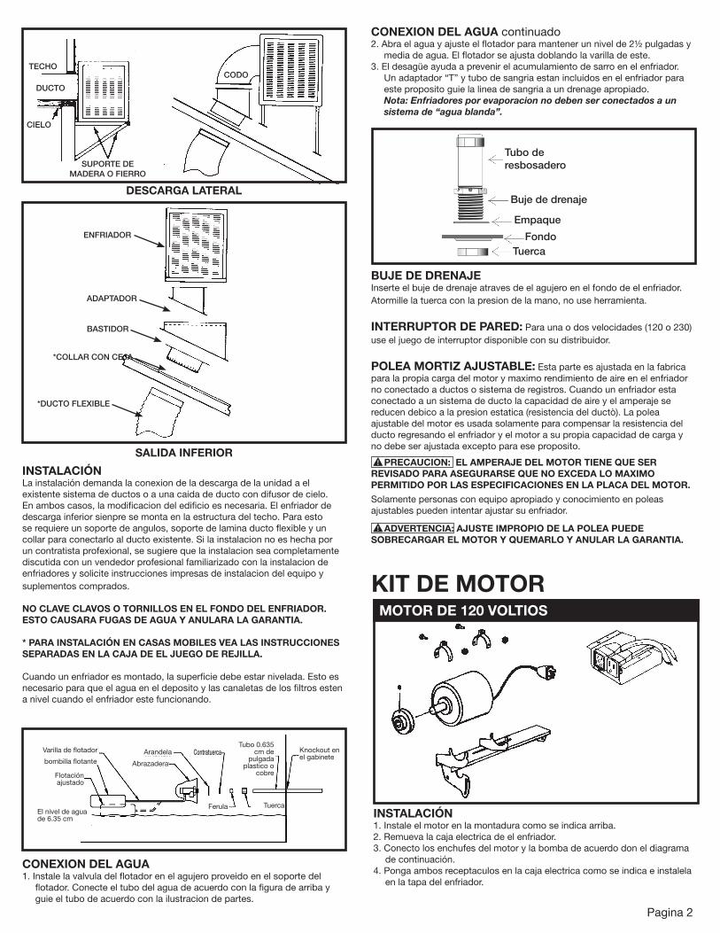
DESCARGA LATERAL
TECHO
DUCTO
CIELO
SUPORTE DE MADERA O FIERRO
CODO
SALIDA INFERIOR
ENFRIADOR
ADAPTADOR
BASTIDOR
*COLLAR CON CEJA
*DUCTO FLEXIBLE
INSTALACIÓNLa instalación demanda la conexion de la descarga de la unidad a el existente sistema de ductos o a una caida de ducto con difusor de cielo. En ambos casos, la modificacion del edificio es necesaria. El enfriador de descarga inferior sienpre se monta en la estructura del techo. Para esto se requiere un soporte de angulos, soporte de lamina ducto flexible y un collar para conectarlo al ducto existente. Si la instalacion no es hecha por un contratista profexional, se sugiere que la instalacion sea completamente discutida con un vendedor profesional familiarizado con la instalacion de enfriadores y solicite instrucciones impresas de instalacion del equipo y suplementos comprados.
NO CLAVE CLAVOS O TORNILLOS EN EL FONDO DEL ENFRIADOR. ESTO CAUSARA FUGAS DE AGUA Y ANULARA LA GARANTIA.
* PARA INSTALACIÓN EN CASAS MOBILES VEA LAS INSTRUCCIONES SEPARADAS EN LA CAJA DE EL JUEGO DE REJILLA. Cuando un enfriador es montado, la superficie debe estar nivelada. Esto es necesario para que el agua en el deposito y las canaletas de los filtros esten a nivel cuando el enfriador este funcionando.
CONEXION DEL AGUA continuado2. Abra el agua y ajuste el flotador para mantener un nivel de 2½ pulgadas y
media de agua. El flotador se ajusta doblando la varilla de este.3. El desagüe ayuda a prevenir el acumulamiento de sarro en el enfriador.
Un adaptador “T” y tubo de sangria estan incluidos en el enfriador para este proposito guie la linea de sangria a un drenage apropiado.Nota: Enfriadores por evaporacion no deben ser conectados a un sistema de “agua blanda”.
Pagina 2
TuercaFerula
Abrazadera
Arandela ContratuercaTubo 0.635
cm de pulgada
plastico o cobre
BUJE DE DRENAJEInserte el buje de drenaje atraves de el agujero en el fondo de el enfriador. Atormille la tuerca con la presion de la mano, no use herramienta.
INTERRUPTOR DE PARED: Para una o dos velocidades (120 o 230) use el juego de interruptor disponible con su distribuidor.
POLEA MORTIZ AJUSTABLE: Esta parte es ajustada en la fabrica para la propia carga del motor y maximo rendimiento de aire en el enfriador no conectado a ductos o sistema de registros. Cuando un enfriador esta conectado a un sistema de ducto la capacidad de aire y el amperaje se reducen debico a la presion estatica (resistencia del ductò). La polea ajustable del motor es usada solamente para compensar la resistencia del ducto regresando el enfriador y el motor a su propia capacidad de carga y no debe ser ajustada excepto para ese proposito.
PRECAUCION: EL AMPERAJE DEL MOTOR TIENE QUE SER REVISADO PARA ASEGURARSE QUE NO EXCEDA LO MAXIMO PERMITIDO POR LAS ESPECIFICACIONES EN LA PLACA DEL MOTOR.
Solamente personas con equipo apropiado y conocimiento en poleas ajustables pueden intentar ajustar su enfriador.
ADVERTENCIA: AJUSTE IMPROPIO DE LA POLEA PUEDE SOBRECARGAR EL MOTOR Y QUEMARLO Y ANULAR LA GARANTIA.
Tubo de resbosadero
Buje de drenaje
Empaque
Tuerca
CONEXION DEL AGUA1. Instale la valvula del flotador en el agujero proveido en el soporte del
flotador. Conecte el tubo del agua de acuerdo con la figura de arriba y guie el tubo de acuerdo con la ilustracion de partes.
KIT DE MOTORMOTOR DE 120 VOLTIOS
INSTALACIÓN1. Instale el motor en la montadura como se indica arriba.2. Remueva la caja electrica de el enfriador.3. Conecto los enchufes del motor y la bomba de acuerdo don el diagrama
de continuación.4. Ponga ambos receptaculos en la caja electrica como se indica e instalela
en la tapa del enfriador.
Varilla de flotador
bombilla flotante
Flotación ajustado
El nivel de agua de 6.35 cm
Knockout en el gabinete
Fondo

A
B
Green
Black White
15A 120V
5 P
in
MotorRecp.
Red
Black
White
Green
OrangeGND
Green
White
Black
Red
Pump
Black
Green
White
Lo
Hi
Com
PowerSupply
3 P
in
Verde
Negro Blanco
15A 120V
NegroVerde
Blanco
3 P
asad
ores
Bomba
Negro
Rojo
Blanco
Verde
Bajo
AltoComRojo
NegroBlancoVerdeNaranja5
Pas
ador
es
A
Receptáculo del motor
GND
Fuente de alimentación
Pagina 3
El alambre color naranja no es usado. Doblelo y cubra el lado expuesto con cinta electrica.
A
MOTOR DE 240 VOLTIOS
El alambre color blanco no es usado. Doblelo y cubra el lado expuesto con cinta electrica o tapa de contacto.
A
MOTOR DE 120 VOLTIOS
B El alambre rojo no es usado en motores de una velocidad. Doblelo y cubra el lado expuesto con cinta electrica o tapa de contacto.
B El alambre rojo no es usado en motores de una velocidad. Doblelo y cubra el lado expuesto con cinta electrica o tapa de contacto.
OPERACION
AJUSTE DE BANDAEl ajuste correcto de la banda es importante y aque el ajuste incorrecto aumenta el consumo de corriente y acorta la duracion de la banda y motor.
Instale la banda sobre ambas poleas. (A) revise la tension de la banda apretandola (defleccionandola). Una tension apropiada permitira una defleccion de ½ a ¾ de pulgada. (B) Para aumentar o disminuir la tension de la banda afloje el tormillo del soporte del motor. Ajuste la banda a la tension deseada y apriete el tornillo.
PRE JUMEDEZCA LOS FILTROSPara una maxima eficiencia de enfriamiento, antes del comienzo inicial de la unidad remueva los filtros del enfriador y rocielos con agua completamente usando una manguera de jardin.
Ponga los filtros remojados en el enfriador y ponga a funcionar el motor y la bomba.
COMPUERTA DE INVIERNO EMPOTRADA (Unidades de descarga inferior solamente)Una caracteristica exclusiva de su enfriador (modelos en el rango de 4800 a 6800 PCM) que es proveido por la compuerta de que cierra completamente. Su enfriador es enviado de la fabrica con la compuerta temporalmente sujetada a el lado de la caja de turbina con un tornillo. Remueva este y guarde la compuerta para uso durante los meses de invierno.
1. Para uso invernal de la compuerta, introduzca esta debajo de la caja de turbina de acuerdo con la figura de arriba.
2. Al echar a andar el enfriador en el verano, remueva la compuerta y guardela en un lugar seguro.
INSTALACIÓN1. Instale el motor en la montadura como se indica arriba.2. Remueva la caja electrica de el enfriador.3. Remueva la bomba de 120 voltios y el receptaculo de la bomba proveidos
con el enfriador y remplacela con una de 240 voltios modelo LSP-94 y el receptaculo de la bomba. (Vea la lista de partes de remplazo).
4. Conecte los enchufes del motor y la bomba de acuerdo con el diagrama de arriba.
5. Ponga ambos receptaculos en la caja electrica como se indica e instalela en la tapa del enfriador.
A
Green
Black Orange
15A 230V
5 P
in
MotorRecp.
Red
Black
Orange
Green
WhiteGND
Green
Orange
Black
Red
Pump
Black
Green
Orange
Lo
Hi
Com
PowerSupply
3 P
in
B
Verde
Negro Naranja
15A 240V
Negro
Verde
NaranjaBomba
Negro
Rojo
Naranja
Verde
BajoAlto
ComRojo
NegroNaranja
VerdeBlanco A
GND
3 P
asad
ores
5 P
asad
ores
Receptáculo del motor
Fuente de alimentación

Pagina 4
MANTENIMIENTOEl enfraidor requiere servicio al menos una vez por año o mas si es necesario. Esto incluye limpieza, lubricacion, ajuste de banda o remplazo (si es necesario) y reemplazo de la paja (aspen).
ADVERTENCIA: SIEMPRE QUE TRABAJE EN EL ENFRIADOR DESCONECTE LA CORRIENTE ELECTRA.
LIMPIEZA1. Remueva los filtros y pongalos al lado.2. Remueva el rebosadero de el buje de drenaje y vacie el deposito de agua.3. Limpie las superficies internas del enfriador con un trapo y agua limpia. NO
USE BROCHAS DE ALAMBRE U OTRO MEDIO QUE RASPE LA PINTURA. NO USE QUIMICOS QUE NO SEAN JABON O DETERGENTE PARA LIMPIAR EL ENFRIADOR.
4. Enjuague el fondo del enfriador completamente.5. Limpie el filtro de la bomba y remueva objetos que obstruyan el flujo del
agua en el adaptador de la manguera en la bomba. Asimismo limpie el adaptador del distribuidor de agua a la manguera.
6. Pinte raspaduras y puntos expuestos dentro del enfriador con un recubrimiento apropiado.
LUBRICADIONLlene las aceiteras en las chumaseras de la flecha con aceite de motor SAE #30, no detergente.
AJUSTE DE BANDARevise la tension de la banda. Reajuste, si esta floja, siguiendo las instrucciones en la seccion de operacion de este manual.
Cable retenedor pad
Aspen pad
Pad frame
REEMPLAZO DE LA PAJA (ASPEN)1. Coloque el armazon del filtro en una superficie plana con los retenedores
de alambre hacia arriba y remuevalos.2. Remueva y desche la paja.3. Limpie el armazo. No use brochas de alambre o quimicos fuertas que
puedan dañar la pintura. Pinte raspaduras y puntos expuestos con pintura apropiada.
4. Revise los agujeros en la canala del armazon cerciorece que no esten obstruidos.
5. Use filtros de paja del tamaño apropiado para el armazon.6. Reinstale los retenedores de alambre.7. Remoje completamente los filtros usando una manguera de jardín antes de
reinstalarlos.
Solución de problemas:La siguiente guía está pensada para ayudarle a diagnosticar y solucionar algunos de los problemas más comúnmente encontrados; de niguna manera esta guía cubre todos los posibles problemas que pueden surgir. Si no puede diagnosticar y corregir el problema, o si persiste, póngase en contacte con un personal de servicio cualificado. Todo el trabajo eléctrico debe ser realizado por, o con la ayuda de un electricista cualificado.
PROBLEMA / SÍNTOMAS PROBABLE CAUSA ACCION CORRECTIVA
Derrame de agua1. Valvula fuera de ajuste2. Flotador atorado3. Valvula defectuosa
1. Adjuste valvula a 2½ pulgadas de profundidad de agua2. Libere el flotador3. Remplasela
La turbina no funciona
1. Electricidad desconectada2. Motor defectuoso3. Interruptor o termostato defectuso4. Banda rota
1. Revise corriente, receptaculo y cordon clavija2. Remplase el motor3. Remplase el interruptor o termostato4. Remplasela
Fusible quemado cortacircuito se apaga
1. Fallas en el alambrado o alambrado incorrectamente2. Motor defectuosa3. Bomba defectuosa
1. Repare o remplase los alambres defectuosos2. Remplase el motor3. Replase bomba
Filtros secos
1. Canaleta del filtro tapada2. Entrada de agua en la bomba obstruida3. Bomba defectuosa4. Linea de agua tapada5. Tubo de distribuidor tapado6. Interruptor defectuoso7. Alambre defectuoso
1. Ajuste la flotación a 6.35 cm de profundidad del agua
2. Eliminar la obstrucción3. Remplase bomba4. Localize and remueva la obstruccion5. Localize y limpie la obstruccion en el tubo6. Remplase el interruptor7. Repare o replase los alambres defectuosos
Enfriador ruidoso1. Turbina roza con la caja de esta2. Polea motriz ruidosa3. Tornillos de turbina flojos
1. Realinie turbina2. Apriete los tornillos opresores3. Apriete los tornillos opresores
Fluojo de aire inadecuado1. Filtro tapado2. Banda floja3. Insuficiente escape de aire en el area ventilada
1. Remplase la paja2. Ajuste la tension de esta3. Abra ventanas o puertas