owner’s manual yeti sb5 · owner’s manual and the manuals supplied by the suspension...
TRANSCRIPT

OWNER’S MANUALYETI SB5

4. 5.
TABLE OF CONTENTSBRAND OVERVIEW 06
FRAME FEATURES 08
GEOMETRY 10
MAINTENANCE SCHEDULE 12
SETUP
OVERVIEW 12
SHOCK SETUP 14
DERAILLEUR HANGER INSTALL 16
CABLE/LINE SETUP 18
TECHNICAL
ASSEMBLY OVERVIEW 20
EXPLODED VIEWS 28
REBUILD KITS 32
LEGAL
WARRANTY 36
CONTACT INFORMATION 37

6. 7.6. 7.
CONGRATULATIONS ON YOUR PURCHASE OF A NEW YETI. WELCOME TO THE TRIBE.We are confident your new bicycle will exceed your expectations for value, performance, and ride quality. Each frameset and component has been custom specified and designed to enhance your riding experience. Whether you are a beginner cyclist, or a seasoned pro, your Yeti bicycle will provide endless hours of two-wheeled fun.
This model specific manual is designed to be used in conjunction with the general Yeti Owner’s Manual and the manuals supplied by the suspension manufactures. If you did not receive the Yeti owner’s manual or the manual provided by the suspension manufacturer download the materials off the Internet, or contact your local dealer.
Bicycling can be a hazardous activity even under the best of circumstances. Proper maintenance of your bicycle is your responsibility and when done properly helps reduce the risk of injury and damage to your bicycle.
This manual outlines basic setup and maintenance recommendations of your new Yeti. Because it is impossible to anticipate every situation or condition that may occur during the assembly, setup, and maintenance of your bicycle, Yeti recommends that all service and repairs be performed by your local authorized Yeti Dealer.
This manual contains many “Warnings” and “Cautions” concerning the consequences of failure to maintain or inspect your bicycle. The word “Warning” indicates a potentially hazardous situation in which , if not avoided, could result in serious injury or death. The word “Caution” indicates a potentially hazardous situation in which, if not avoided may result in minor injuries or damage to your bicycle or a component of your bicycle. Be sure to read and understand all of the Warnings and Cautions listed in the manual.
Warning: Make sure you review and understand the warnings, instructions, and content of this manual and accompanying manuals for your bicycle.
Warning: Technological advances have made bicycles and bicycle components more complex and the pace of innovation is increasing. It is impossible for this manual or the accompanying manuals to provide all the information required to properly repair and/or maintain your bicycle. In order to help minimize the chances of an injury, it is critical for you to have work performed by an authorized Yeti retailer.

8. 9.
THE LOWDOWN ON THE SB5 AND ITS FEATURES.
1. The SB5 delivers 5 inches (127mm) of travel with our patented Switch Infinity Technology. Efficient pedaling performance while still smooth and continuous when the going gets rough.
2. Top of the top Turq Series frames and our Carbon series both offer the same geometry and efficiency in all models.
3. Colleted pivot axles help create a stiff interface between the front and rear triangles. Custom Enduro Max sealed bearings keep things moving freely at the pivots.
4. The SB5 does away with the front derailleur mount, making it a 1x drive specific frame. This increases stiffness in the frame, making the SB5 one of the stiffest bikes in our lineup.
5. ISCG 05 chain guide mounts are included on the SB5 in case you want to go for some extra drivetrain security in the rowdy sections.
6. Using our inset head tube on the SB5 allows for a larger head tube with more area, increased stiffness, and lower overall ride height without compromising any performance.
7. The SB5 uses a metric 50mm stroke, 210mm eye to eye Float EVOL shock, by Fox Racing Shox.
8. Custom guards on the seat stay, chain stay and down tube keep things quiet while riding and protect the frame.
9. The SB5 features internally molded routing tubes for all cables, making the bike quiet and clean looking as well as reducing maintenance and cable rub.
10. Dedicated 12 x 148 Boost dropouts and integrated hanger with axle threads for strength, stiffness, ease of hanger and wheel installation.
11. An already low stand over is made even lower in our small and extra small SB5 frames giving them the lowest stand over clearance in the trail bike world.
1. SWITCH INFINITY TECHNOLOGY PATENTED SUSPENSION SYSTEM
2. TURQ AND CARBON SERIES FRAMES
3. COLLET AXLE SYSTEM ON PIVOTS REDUCES BEARING WEAR
4. OPTIMIZED FOR 1X DRIVETRAINS ONLY
5. ISCG 05 CHAINGUIDE MOUNTS
6. TAPERED INSET HEAD TUBE (44MM/56MM)
7. SUSPENSION BY FOX (210MM X 50MM)
8. CUSTOM DEBRIS AND CHAIN SLAP GUARDS
9. INTERNALLY MOLDED CARBON CABLE ROUTING TUBES
10. INTEGRATED AXLE AND DERAILLEUR HANGER SYSTEM
11. INDUSTRY LEADING LOW STAND OVER

10. 11.
GEOMETRY
FITX-SMALL 4’11” (150 CM) - 5’3” (160 CM)
SMALL 5’3” (160 CM) - 5’7” (170 CM)
MEDIUM 5'7" (170 CM) - 5'11" (180 CM)
LARGE 5'11" (180 CM) - 6'3" (191 CM)
X-LARGE 6'1" (191 CM) - 6'6" (198 CM)
FOX 34 / 150MM FORK
XS SM MD LG XL
A WHEEL 27.5” 27.5” 27.5” 27.5” 27.5”
B REACH 382 402 424 444 463
C EFF. TOP TUBE 552 578 603 629 654
D STACK 585 600 610 625 645
E HEAD TUBE LENGTH 100 116 127 144 165
F SEAT TUBE LENGTH 381 419 445 483 521
G EFF. SEAT TUBE ANGLE 73.7 73.7 73.6 73.5 73.5
H HEAD TUBE ANGLE 66.5 66.5 66.5 66.5 66.5
I MECH. TRAIL 96 96 96 96 96
J BB DROP 13 13 13 13 13
K EST. BB HEIGHT 338 338 338 338 338
L CHAINSTAY LENGTH 437 437 437 437 437
M FRONT-CENTER 697 705 731 758 786
N WHEELBASE 1116 1142 1168 1195 1222
O STANDOVER 668 683 724 737 749
P AXLE TO CROWN 539 539 539 539 539
Q FORK OFFSET 44 44 44 44 44
*All measurements are in millimeters
Q
I
P
E
N
H
C
O
L
B
D
G
K
F
J
J
M A

12. 13.
KEEP YOUR YETI FRESH AND CLEANOVERVIEW TORQUE
KEY TORQUE SPECS
Following these guidelines will help maintain the performance of your bicycle and prevent more serious problems from arising. It is important to remember that service intervals can vary depending on climate, trail conditions and riding frequency. If you are unsure about working on your own bicycle, contact your authorized Yeti Dealer for more information on general bicycle maintenance.
Yeti strongly recommends using a torque wrench when assembling your frame. Torque specifications for individual parts on the SB5 are listed below, as well as in the step by step assembly instructions later in the manual. For general bicycle maintenance please consult the torque specifications of the component you are adjusting.
PART NUMBER DESCRIPTION TORQUE (NM)
300030151 BOLT TI MALE (M6 X 1 X 12MM) 7
300030057 INFINITY LINK BOLTS (M6 X 1) 12
300040484 UPPER LINK COLLET AXLE (M10 X 10) 3
300040486 UPPER LINK COLLET WEDGE (M5 X .8) 8
300040483 LOWER LINK COLLET AXLE (M10 X 10) 3
300040486 LOWER LINK COLLET WEDGE (M5 X .8) 8
300040485 MAIN PIVOT COLLET AXLE (M15 X 1.5) 3.5
300040454 MAIN PIVOT COLLET WEDGE (M8 X 1.25) 14
WE
EK
LY
MO
NTH
LY
3 M
ON
THS
AN
NU
ALL
Y
CLEAN AND LUBE CHAIN
CHECK TIRE PRESSURE
CLEAN BIKE OF MUD AND DEBRIS
CHECK BRAKE FUNCTION
CHECK SHOCK PRESSURE, IF APPLICABLE
CHECK FOR LOOSE BOLTS AND TIGHTEN, IF NECESSARY
CHECK HEADSET AND TIGHTEN / LOOSEN, IF NECESSARY
THOROUGHLY CLEAN PIVOT POINTS WITH A RAG (DO NOT LUBRICATE)
LUBE INFINITY LINK EVERY 40 HRS. (YETI HEAVY MOLYBDENUM GREASE)
CHECK / REPLACE BRAKE PADS, IF NECESSARY
CHECK TIRES FOR WEAR
CHECK SPOKE TENSION AND RETENTION, IF NECESSARY
CHECK CHAIN FOR WEAR AND REPLACE IF NECESSARY
COMPLETE TUNE-UP PERFORMED BY AN AUTHORIZED YETI DEALER
SCHEDULE

14. 15.
SHOCK SETUP
Inspect your shock for any visible damage. If oil is leaking or you notice any damage to the surfaces or seals, please contact the Fox Racing Shox service center for repair at 800.FOX.SHOX or your local bike shop.
Shock set-up can fluctuate greatly based on the rider. The set-up guide is intended as a base line to get the rider started. Experiment with your settings to find the set-up that works best for you.
We recommend starting out with 30% sag, which is 15mm of shock stroke. Your total shock stroke is 51mm’s.
YETI TIPS TOOLS NEEDED• Shock Pump• Metric Tape Measure
01. AIR PRESSURE 02. SAGThe main air spring controls sag. For the SB5 to ride properly it is important to setup the shock with the correct amount of sag. The SB5 works best with 15MM of measured sag. To increase sag, reduce the main spring air pressure. To reduce sag, increase the main spring air pressure. Always ycle the shock 5-10 times after any pressure adjustment to equalize the EVOL chamber before measuring sag.
Once you have set your baseline air pressure and cycled the shock you are ready to measure the sag. To measure the sag slide the travel indicator (O-Ring) up against the shock body. With a friend supporting the bike and with the compression set “open,” sit on the saddle and allow your body weight to compress the shock. Once you have compressed the shock, get off the bike and measure the distance between the shock body and the new position of the travel indicator (O-Ring). This is your sag.
*All clicks are counted counter-clockwise, rotating from the all the way “in” or clockwise dial position.
ADJUSTMENT SETTING
BASELINE AIR SPRING SETTING RIDER WEIGHT -10 LBS
MEASURED SAG (MM) 15MM
REBOUND 5-7 CLICKS*
COMPRESSION ADJUSTMENT OPEN
QUICK START GUIDE
03. REBOUND 04. COMPRESSIONRebound is adjusted using the red knob located by the front shock mount. Clockwise will slow the rebound, counter clockwise will speed it up. Rebound needs to be tuned to rider preference and air spring pressure. Too slow and the bike will feel like it is not ready for the next bump. Too fast and it will feel like the bike is bucking you off after an impact.
Low-speed compression is adjusted in the “open” position using the black tabs and has 3 positions. 1 is wide open, 3 is more firm. This adjustment is subtle. The blue lever has 3 positions: Open, Medium and Firm. For our bikes, unless you are on pavement on the way to the trail, we recommend using the “open” setting. The Switch Infinity design will do the rest!

16. 17.
01. HANGER PREP 02. HANGER CAP SEATLightly grease the threads and outside surface of the hanger and cap where it interfaces with the frame. The hanger will fit into its space on the inside of the swing arm and should press easily into the frame.
Place the hanger into the recess on the inside of the swingarm. Thread the hanger cap into the hanger. The hanger cap REVERSE threads into the hanger from the outside of the swing arm. Start threading the cap by hand.
03. TIGHTENING Using a 6mm allen key, tighten the hanger cap into the hanger. REMEMBER, it is REVERSE THREADED. Follow the “Tighten” arrow on the cap. Finish tightening with a torque wrench if available.
*Torque to 80 in/lbs (9Nm)
NOTE: The hanger cap is REVERSE THREADED. Be careful not to strip out the Hanger tool faces. The cap is marked with a tighten direction arrow.
Inspect the frame around the hanger seat for any suspicious damage to the carbon any time you replace a derailleur hanger, especially if you are replacing the hanger due to damage to the hanger.
YETI TIPS TOOLS NEEDED• 6mm Allen key• Grease
DERAILLEUR HANGER INSTALL

18. 19.
Your rear brake and shifter housing should run parallel around the left side of the head tube. Run the shifter housing and the brake housing into the individual ports at the head tube. The brake housing will exit on the non-drive side port just in front of the Infinity Link. The shift housing comes out of the port on the drive side. Both housings will enter the swingarm directly as shown above on the right. CONTINUED
Caution: The failure to properly route housing can cause malfunction of the mechanism that could result in injury.
The rear derailleur housing will exit the swing arm via the port on the side of the seat stay right in front of the rear derailleur. Create a gentle curve to the derailleur and adjust to the manufacturers specifications.
The SB5 is designed to use an internally routed dropper post. The cover on the top of the down tube right in front of the seat tube/down tube junction reveals the final routing for the seat post. Remove the cover using a 2.5mm allen wrench. This will expose the channel the dropper housing passes through. Thread your housing from the head tube down into that channel. Guide the housing through the channel and out the other end and into the seat tube. Once you have the seatpost installed and adjusted correctly, reinstall the cover.
CABLE SETUP The SB5 uses internal molded tubing to make cable threading a cinch! No more rattling cable housing in your frame and no more fishing for cables required. Simply thread your housing through the correct port and you are done. Follow these simple instructions to get each housing in the right place.
REAR BRAKE AND DERAILLEUR
REAR DERAILLEUR CONTINUED
INTERNALLY ROUTED SEAT POST
REAR BRAKE CONTINUEDThe rear brake housing exits the swing arm on the inside of the chain stay and goes directly up to the caliper. If your caliper allows, adjust the housing attachment angle to reduce the bend in the cable as much as possible.

20. 21.
FRAME ASSEMBLY
Make sure your tools are in good condition. A worn allen key can round the hex on a bolt not allowing for proper torque.
Torque settings are listed throughout the instructions and on page 13 of this manual. It is important to prep all bolt threads. The instructions denote whether to use a Loctite compound or grease.
YETI TIPS TOOLS NEEDED
Warning: Service on Yeti bicycles requires special knowledge and tools. Yeti Cycles recommends that all service and repairs be performed by an authorized Yeti Dealer
• 2.5mm allen key• 5mm allen keys• 4mm allen keys• 10mm allen key• Guide pin tool (Or two)• Torque wrench• Grease• Blue (242) Loctite All the parts you’ll need to get your SB5 frame
assembled. Please refer to the exploded view later in this manual for more information.
Slip washers (300030214) onto and apply blue (242) Loctite to the 4 bolts (300030057) that secure the Switch Infinity Link to the frame.
Insert the bolts with washers on them into the frame and hang the black Infinity Link spacers from them. Orient them so that the flat surfaces are facing the opening in the frame where the Infinity link will go.
01. 02.
03. 04.Rock the Infinity Link into place capturing the black spacers against the frame. Be sure that the spacers do not rotate when you are installing the link. Hold the link in place by hand and thread the bolts into the link.

22. 23.
ASSEMBLY
Place the spacing washers (300020049) on the lower (narrow) end of the link. The grease should help hold them in place.
Insert the link into the frame and insert the lower link axle (300040483) to hold it all in place. Despite the picture, apply grease to the threads and shaft of the pivot axle. No LocTite needed.
05. 06.
08.07.
Lightly grease the bearing surfaces on your link (200020261).
Using a torque wrench, finish tightening the Infinity Link bolts using a crossing pattern.
*Torque to 12 Nm
ASSEMBLY
Insert the collet axle nut (300030287) in the corresponding keyed hole and thread the axle in using a 5mm allen wrench. The axle acts like a headset and is meant to preload the bearings.
*Torque: 3 Nm
Install the lower link collet wedge. (300040486) Grease the threads and the wedge. Tighten with a 4mm allen wrench and finish with a torque wrench.
*Torque: 8 Nm
Grease the threads and shaft of the main pivot axle. (300040485)
Slide the swingarm into place, aligning the main pivot. Push the main pivot axle through the swingarm and Infinity Link from the non-drive side. NOTE: You may want to use a guide pin (200020118) to assist in aligning the sleeve in the Infinity link.
09. 10.
11. 12.
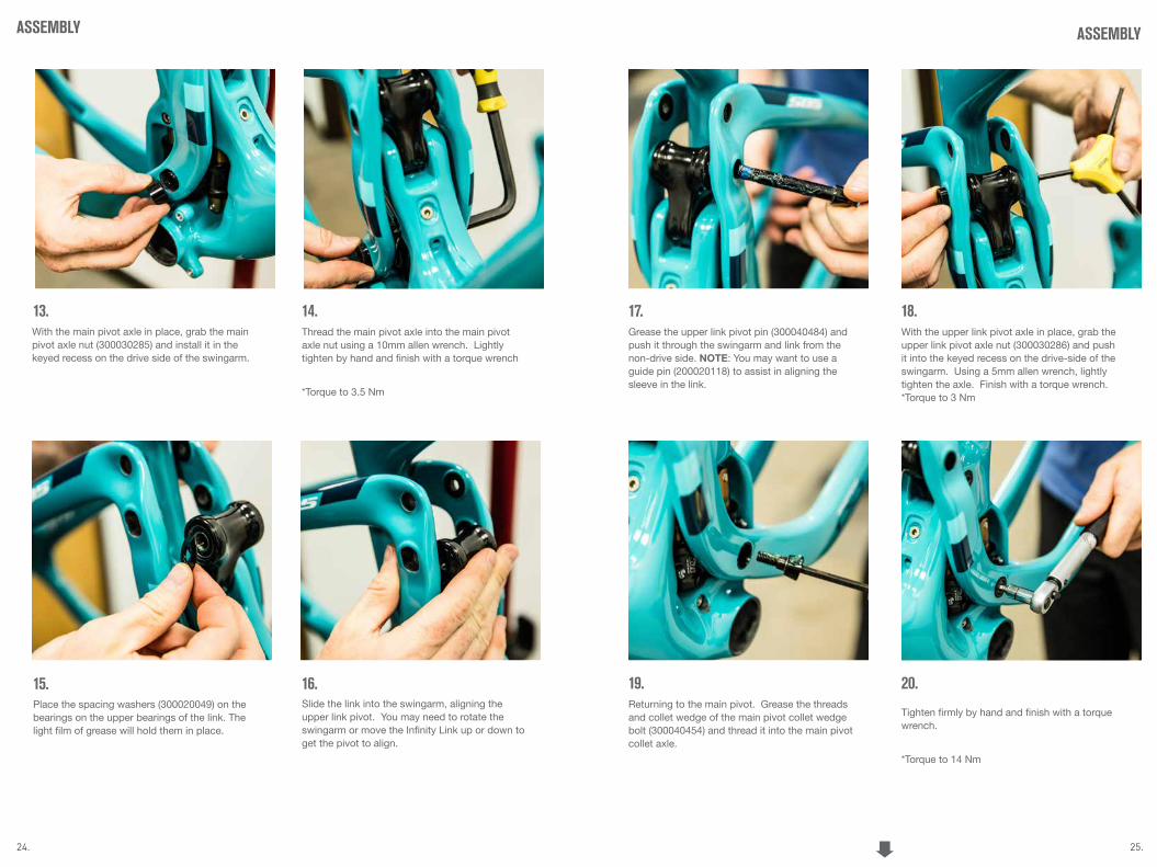
Grease the upper link pivot pin (300040484) and push it through the swingarm and link from the non-drive side. NOTE: You may want to use a guide pin (200020118) to assist in aligning the sleeve in the link.
24. 25.
Thread the main pivot axle into the main pivot axle nut using a 10mm allen wrench. Lightly tighten by hand and finish with a torque wrench
*Torque to 3.5 Nm
Place the spacing washers (300020049) on the bearings on the upper bearings of the link. The light film of grease will hold them in place.
Slide the link into the swingarm, aligning the upper link pivot. You may need to rotate the swingarm or move the Infinity Link up or down to get the pivot to align.
13. 14.
15. 16.
ASSEMBLY
With the main pivot axle in place, grab the main pivot axle nut (300030285) and install it in the keyed recess on the drive side of the swingarm.
ASSEMBLY
17.With the upper link pivot axle in place, grab the upper link pivot axle nut (300030286) and push it into the keyed recess on the drive-side of the swingarm. Using a 5mm allen wrench, lightly tighten the axle. Finish with a torque wrench. *Torque to 3 Nm
18.
Returning to the main pivot. Grease the threads and collet wedge of the main pivot collet wedge bolt (300040454) and thread it into the main pivot collet axle.
19.
Tighten firmly by hand and finish with a torque wrench.
*Torque to 14 Nm
20.

26. 27.
Slide the shock into place in the frame. Align the front shock mount using a guide pin (200020118) first.
With the front mount guide pin in place, align rear shock mount with a second guide pin. NOTE: If a second guide pin is not available simply install the front mount hardware (see steps 24 and 25) and re use the guide pin in rear shock mount.
Place a 8.5mm x 12.5mm washer (300030069) over the front shock mounting pin (300030153) and slide the mounting pin over the blunt end of the guide pin, pushing it through the frame.
22.
23. 24.
ASSEMBLY
21.Grease the threads and collet wedge on the upper link collet bolt (300040486) and thread it into the upper link pivot collet axle with a 4mm allen wrench. Firmly tighten by hand and finish with a torque wrench.
*Torque to 8 Nm
ASSEMBLY
Place the 6.5mm x 12.5 washer (300030062) over a Male Ti bolt (300030151). Apply Blue LocTite to the threads. Using two 5mm allen wrenches tighten the male bolt into the shock mounting pin. Finish using a torque wrench.
*Torque to 7 Nm
25.Thread a Male Ti bolt (300030151) into the rear shock mounting pin (300030289) and thread all the way in. Place a 8.5mm x 12.5mm washer (300030069) over the shock mounting pin assembly and slide it through the swingarm and shock using the blunt end of the guide pin to guide it through.
26.
FRAME ASSEMBLY IS COMPLETE.Place the 6.5mm x 12.5 washer (300030062) over a Male Ti bolt (300030151). Apply Blue LocTite to the threads. Using two 5mm allen wrenches tighten the male bolt into the shock mounting pin assembly. Finish using a torque wrench.
*Torque to 7 Nm
27.

28. 29.
EXPLODED VIEW
5.1.1
Grease
Loctite
5.1.1
5.2
5.2
5.1.2
5.1.2
5.2
5.2
5.1.2
5.1.2
5.1.3
5.1.4
5.2
5.2
5.1.2
5.1.2
5.2
5.2
5.1.2
5.1.2
5.1.3
5.1.4
5A
5C
1.6
1.8
1.7
5.45.6
5.17
5.17
5.16
5.16
1.5
1.5
5.7
3
1.1 1.2
4.3
4
1.3
5.115.12
5.135.14
4.2
1.4
5.4
5.135.125.15
5.9
5.8
5.3
5.13 5.14
5.10
5.5
2.4
1.51.5
2.2.1
2.2.2

30. 31.
ITEM# PART # DESCRIPTION QTY
1 N/A SB5 FRONT TRIANGLE ASSEMBLY
1.1 N/A SB5 FRONT TRIANGLE 1
1.2 300070006 ICE AXE HEAD BADGE 1
1.3 300060072 YETI SEAT CLAMP STANDARD 1
1.4 300040495 FRONT TRIANGLE PORT COVER 1
1.5 300030291 (M4 X 0.7 X 10MM) BLACK 3
1.6 400100144 DT PROTECTOR 1
1.7 300030010 BOLT-CAP H20 (M5 X 0.8 X 16MM) 2
1.8 300030148 WASHER 5.1X8.9X1MM 2
2 N/A SB5 SWING ARM ASSEMBLY
2.1 N/A SB5 SWING ARM 1
2.2 300060073 12X148 HANGER STD KIT GEN3 1
2.2.1 300060074 12X148 HANGER STANDARD GEN3 1
2.2.2 300060075 12X148 HANGER CAP GEN3 1
2.3 400100141 SB5 CS/SS PROTECTOR 1
2.4 400100142 SB5 CHAINSUCK GUARD 1
2.5 400100143 SB5C CS LOWER PROTECTOR 1
3 200020201 FOX LINEAR BEARING 74.0MM ASSEMBLY
4 N/A SHOCK ASSEMBLY SB5
4.1 N/A FOX FLOAT DPS 210MM X 50MM 1
4.2 N.A FOX MOUNT KIT 40.0MM 1
4.3 N/A FOX MOUNT KIT 25.0MM 1
5 N/A SB5 FRAME ASSEMBLY PARTS
5.1A 200020266 SB5 ALLOY LINK (W/BEARINGS) 1
5.1C 200020260 SB5 CARBON LINK (W/BEARINGS) 1
5.1.1A 200020264 SB5 ALLOY LINK 1
5.1.1C 200020261 SB5 CARBON LINK 1
EXPLODED VIEW PARTS LISTITEM# PART # DESCRIPTION QTY
5.1.2 300020050 BEARING 6900-2RS-MAX 22X10X6 4
5.1.3 300030281 SPACER 10MM X 29.0MM 1
5.1.4 300030282 SPACER 10MM X 6.0MM 1
5.2 300020049 INNER RACE EXTENDER 10MM 4
5.3 300040484 COLLET AXLE 10X53.5X13.0 M10X1.0 1
5.4 300040486 COLLET WEDGE SUB-ASSEMBLY 10MM 2
5.4.1 300030284 COLLET BOLT M5X.8 1
5.4.2 300030283 COLLET WEDGE 10MM 1
5.4.3 300040482 SPIRAL RETAINING RING 1
5.5 300030286 COLLET NUT M10X1X12MM 1
5.6 300040483 COLLET AXLE 10X30.5X9.0 M10X1.0 1
5.7 300030287 COLLET NUT M10X1X8MM 1
5.8 300040485 COLLET AXLE 15X52.5SX13.0T M15X1.5 1
5.9 300040454 COLLET WEDGE SUB-ASSEMBLY GEN2 1
5.9.1 300030268 COLLET BOLT M8X1.25 1
5.9.2 300030267 COLLET WEDGE 15MM 1
5.9.3 300040450 SPIRAL RETAINING RING 1
5.10 300030285 COLLET NUT M15X1.5X12MM 1
5.11 300030153 BOLT-TI-FEMALE 8.0X34.0MM GEN2 1
5.12 300030069 WASHER 8.5X12.5X0.5 MM 2
5.13 300030151 BOLT TI MALE M6X12.0MM 3
5.14 300030062 WASHER 6.5X12.5X0.5 MM 2
5.15 300030289 BOLT-TI-STUD 8.0X49.0MM 1
5.16 300030057 BOLT-CAP (M6 X 1 X 20 MM) 4
5.17 300030214 WASHER (10X6.2X1MM) 4

32. 33.
REBUILD KITSPART # DESCRIPTION QTY
200020286 SB5 MASTER REBUILD KIT
300020049 BEARING RACE EXTENDER 23X10 4
300020050 BEARING 6900 2RSMAX 22X10X6 4
300030057 BOLT CAP M6X1X20 4
300030062 WASHER SS 6.5MM ID 12.5 OD .5M 2
300030069 WASHER SS 8.5MM ID 12.5MM OD 2
300030151 BOLT TI MALE M6X 12MM 3
300030153 BOLT-TI-FEMALE 8.0X34.0MM 1
300030214 WASHER 10 X 6.2 X 1 4
300030281 SPACER 10X29.0MM 1
300030282 SPACER 10X6.0MM 1
300030285 COLLET AXLE NUT M15X1.5X12 1
300030286 COLLET AXLE NUT M10X1X12 1
300030287 COLLET AXLE NUT M10X1X8 1
300030289 STUD-TI-FEMALE 8X49.0MM 1
300030291 BOLT BUTTON HEAD M4X.7X10 BLACK 3
300040454 COLLET-WEDGE ASSEMBLY GEN2 1
300040483 AXLE COLLET 10X30.5SX9T 1
300040484 AXLE COLLET 10X53.5SX13T 1
300040485 AXLE COLLET 15X52.5SX13T 1
300040486 COLLET WEDGE ASSEMBLY - M10 2
300040495 PORT COVER SB5-C 1
200020288 SB5 BEARING REBUILD KIT
300020050 BEARING 6900 2RSMAX 4
300030281 SPACER 10X29.0MM 1
300030282 SPACER 10X6.0MM 1
PART # DESCRIPTION QTY
200020287 SB5 HARDWARE REBUILD KIT
300020049 BEARING RACE EXTENDER 23X10 4
300030057 BOLT CAP M6X1X20 4
300030062 WASHER SS 6.5MM ID 12.5 OD .5M 2
300030069 WASHER SS 8.5MM ID 12.5MM OD . 2
300030151 BOLT TI MALE M6X12MM 3
300030153 BOLT-TI-FEMALE 8.0X34.0MM 1
300030214 WASHER 10 X 6.2 X 1 4
300030285 COLLET AXLE NUT M15X1.5X12 1
300030286 COLLET AXLE NUT M10X1X12 1
300030287 COLLET AXLE NUT M10X1X8 1
300030289 STUD-TI-FEMALE 8X49.0MM 1
300030291 BOLT BUTTON HEAD M4X.7X10 BLACK 3
300040454 COLLET-WEDGE ASSEMBLY GEN2 1
300040484 AXLE COLLET 10X53.5SX13T 1
300040483 AXLE COLLET 10X30.5SX9T 1
300040484 AXLE COLLET 10X53.5SX13T 1
300040485 AXLE COLLET 15X52.5SX13T 1
300040486 COLLET-WEDGE ASSEMBLY - M10 2
300040495 PORT COVER SB5-C 1
200020231 FOX LINEAR BEARING 74.0MM SB5
200020201 FOX LINEAR BEARING 74.0MM ASSE 1
300030057 BOLT CAP M6X1X20 4
300030214 WASHER 10 X 6.2 X 1 4

34. 35.
PART # DESCRIPTION QTY
400100147 PROTECTOR KIT SB5
400100141 PROTECTOR SB5 CS/SS 1
400100142 PROTECTOR SB5 CHAIN SUCK 1
400100143 PROTECTOR SB5 CS LOWER 1
400100144 PROTECTOR SB5 DT 1
400100146 SB5 PROTECTOR DECAL KIT 1
SB5 MISCELLANEOUS PARTS
200020284 LINK CARBON SB5 MATTE W/BEARING N/A
200020260 LINK CARBON SB5 GLOSS W/BEARING N/A
200020266 LINK ALLOY SB5 W/BEARING N/A
300060073 12X148 HANGER STD KIT BLACK N/A
300060077 12X148 HANGER STD KIT TURQUOISE N/A
REBUILD KITS CONTINUED
36.
WARRANTYYETI LIMITED (5) FIVE YEAR FRAME WARRANTY (applies to SB5.5 / SB5 / Beti SB5 / SB5+ / SB6 / ASR / Beti ASR / Infinity Link)
Yeti Cycles will repair or replace, at its option, any of the above listed frames it determines to be defective due to defective materials and/or workmanship. The (5) five year limited warranty is conditioned upon the bicycle being ridden under normal conditions and having been properly maintained. This warranty does not apply to the components attached to the frameset such as suspension components, wheels, drive train, brakes, seat post, handlebar and stem. This warranty applies only to the original owner and is non-transferable. This warranty is void if the bicycle was not properly assembled by an authorized Yeti dealer.
ADDITIONAL CONDITIONS These limited warranties do not apply to normal wear and tear, nor to claimed defects, malfunctions or failures that result from abuse, neglect, improper assembly, improper maintenance, alteration, collision, crash or misuse. The original owner shall pay all labor charges connected with the repair or removal of all components. Under no circumstance does this limited warranty include the cost of travel or shipment to and from an authorized Yeti dealer. In order to exercise your rights under these limited warranties, the bicycle or frameset must be presented to an authorized Yeti dealer, together with proof of purchase.
*The above warranties have been in effect since January 2012. For warranty information on Yeti frames sold prior to that date please consult your local authorized dealer.
NO FAULT REPLACEMENT POLICY Yeti Cycles will make replacement parts available at a minimum charge to the original owner in the event of a crash or any other non-warranty situation. Yeti Cycles does this at its sole discretion and reserves the right to refuse this offer.
PRODUCT LIFE CYCLE Every YETI frameset has a useful product life cycle. The length of that useful product life cycle will vary depending on the construction and the materials of the frameset, maintenance and care the frameset receives , and the amount and type of use the frameset is subjected to over its life. YETI recommends that an authorized YETI dealer should inspect the frame for stress annually. Frame stress could cause potential failure and the signs are usually apparent in the form of cracks, fracture lines, deformation, dents, and any other visual indicators of abnormality. These safety checks for frame stress are important to prevent accidents, injury to the cyclist, and product failure of a YETI frameset.
DISCLAIMER YETI Cycles is not responsible for any damages to you or others arising from riding, transporting or other use of your bicycle. In the event that your frame breaks or malfunctions, YETI Cycles shall have no liability or obligation beyond the repair or replacement of your frame pursuant to the terms outlined in the warranty.
*If you have a warranty concern, please contact your authorized Yeti dealer.
YETI CYCLES 621 Corporate Circle, Unit B Golden, CO 80401 (p) 303-278-6909 (f) 303-278-6906 www.yeticycles.com
BUSINESS HOURS Monday-Friday
8AM-11:30AM, 1:00PM-5:30PM (Mountain Time)