owner’s manual · 2017-06-28 · 10007825 rev. b asd-120 2.0 inst. 10-15 asd-120 2.0 owner’s...
TRANSCRIPT

10007825 REV. B ASD-120 2.0 INST. 10-15
ASD-120 2.0OWNER’S MANUALSIX CHANNEL SEQUENCING POWER DISTRIBUTION
START
SEQUENCE
REMOTE
DLYADJ
DELAY A DELAY B D
ELAY C PHASE
X Y Z
DELAY D DELAY E D
ELAY F
OFF
ON
1 2 3 4 5 6 7
ALWAYS ON
ALWAYS OFF
ASD-120 2.0
120 AMP POWER SEQUENCER
(SEE COVER PLATE)
INPUT 120 / 3Ø, 208 / 240 VAC 14400 WATTS – 120 AMPS MAX 20A MAX
DELAY A
20A MAX
DELAY B
20A MAX
DELAY C
20A MAX
DELAY D
20A MAX
DELAY E
20A MAX
DELAY F
FORCE OFF
DELAY OUTPUTS
REMOTE
NC A B C D E F NO
12V STAT REM GND
WARNING! ELECTRIC SHOCK HAZARD. CONNECTION OF A POWER INPUT CABLE TO THIS DEVICE AND TO A POWER SOURCE MUST BE
DONE BY QUALIFIED PERSONNEL ONLY. DANGER: MANIPULER SEL ON LES INSTRUCTIONS DU
FABRICANT ET CONFIER LA MAINTENANCE A UN T ECHNICIEN QUALIFIE
DRY RELAY CONTACTS - RATING 48V / 1 AMP

INTRODUCTION
Thank you for choosing a Furman product and congratulations on your choice of the ASD-120 2.0. The ASD-120 2.0 is a six channel power sequencing device intended for use in installations where multiple electrical loads must be powered on and off in a delayed and orderly sequence. Typical applications for the ASD-120 2.0 include: touring PA or sound reinforcement systems, musical or theatrical acts, mobile recording facilities, and on-location film or video shoots. Essentially, any situation where AC power must be distributed to multiple circuits and activated or deactivated in discrete stages would benefit from the use of an ASD-120 2.0.
Please read this manual completely and carefully and review the installation man-ual before installing or applying power to your ASD-120 2.0. Those familiar with the ASD-120 will recognize that the ASD-120 2.0 provides the same functionality as the preceding version but adds a number of features that the user might appreciate. These new features include the following:
1
BEFORE YOU BEGIN, PLEASE INSPECT UPON RECEIPT
START
SEQUENCE
REMOTE
DLYADJ
DELAY A DELAY B D
ELAY C PHASE
X Y Z
DELAY D DELAY E D
ELAY F
OFF
ON
1 2 3 4 5 6 7
ALWAYS ON
ALWAYS OFF
ASD-120 2.0
120 AMP POWER SEQUENCER
(SEE COVER PLATE)
INPUT 120 / 3Ø, 208 / 240 VAC 14400 WATTS – 120 AMPS MAX 20A MAX
DELAY A
20A MAX
DELAY B
20A MAX
DELAY C
20A MAX
DELAY D
20A MAX
DELAY E
20A MAX
DELAY F
FORCE OFF
DELAY OUTPUTS
REMOTE
NC A B C D E F NO
12V STAT REM GND
WARNING! ELECTRIC SHOCK HAZARD. CONNECTION OF A POWER INPUT CABLE TO THIS DEVICE AND TO A POWER SOURCE MUST BE
DONE BY QUALIFIED PERSONNEL ONLY. DANGER: MANIPULER SEL ON LES INSTRUCTIONS DU
FABRICANT ET CONFIER LA MAINTENANCE A UN T ECHNICIEN QUALIFIE
DRY RELAY CONTACTS - RATING 48V / 1 AMP
This box should include the following items:
1. Model ASD-120 2.0
2. Two adjustable rear rack mounting ears
3. Security cover with Two 6-32 3/8” Screws
4. One pair of security keys
5. Removable Rack Handles
6. 1.5 in. Cable Clamp (Please see wiring instructions)
7. Two pin Phoenix-type connector
8. Four pin Phoenix-type connector
9. Eight pin Phoenix-type connector
3
8
1
6
7
4
2
9
• All settings, options, and controls are now easily accessible from the front panel• The output capacity of the 12V remote interface has been increased to 250mA • Maximum sequencing delay has been increased to 7 minutes per stage• The operation of the Remote interface has been harmonized with other Furman products• The Force Off warning is now highly visible • The sequencing bypass switches are now low profile to prevent inadvertent operation• A security cover has been added to prevent unauthorized access.• Rear rack mounting ears have been added to enhance road worthiness• Phoenix-type connectors have been used to simplify installation
Please note:
Because the ASD-120 2.0 switches hazardous voltages and high currents, we recommend that installation be performed by a qualified electrician. For safe operation, the ASD-120 2.0 must be installed in accordance with local/municipal and National Electrical Codes. Please feel free to contact Furman Technical Ser-vices if you have any questions or concerns regarding the installation, operation, or service of your ASD-120 2.0.
IMPORTANT SAFETY NOTE:
While the subject of attaching a power cable to the ASD-120 2.0 is covered in the Wiring Instructions, the connection to utility power or generator power is not. We strongly recommended that the ASD-120 2.0 be installed by a qualified electrician. Please refer to the “Wiring Instructions” section in this manual.
5

2
Introduction, Before You Begin, and Important Safety Note__________________________________________________________________ 1
Important Safety Instructions _____________________________________________________________________________________ 2
Wiring Instructions ___________________________________________________________________________________________ 3, 4
Rear Rack Mounting Ears _________________________________________________________________________________________ 4
Product Features _____________________________________________________________________________________________ 5
Product Overview ___________________________________________________________________________________________ 6, 7
Front Panel Configurations and Features_______________________________________________________________________ 7, 8, 9, 10
ASD-120 2.0 Programming Summary_______________________________________________________________________11, Back Cover
Rear Panel Control Terminal Interface ________________________________________________________________________________12
Advanced Installation Topics___________________________________________________________________________________13, 14
Local Operating Modes____________________________________________________________________________________15, 16, 17
Product Installation Examples_______________________________________________________________________________ 18, 19, 20
Specifications _______________________________________________________________________________________________ 21
Warranty Information __________________________________________________________________________________________ 22
TABLE OF CONTENTS
CAUTION
• The ASD-120 2.0 remote interface differs from the original ASD-120. While the original ASD-120 REM terminal input was compatible with AC voltages, the ASD-120 2.0 is not. For example, if an original ASD-120 is to be controlled by the ASD-120 2.0, please use the Direct Current 12V and REM terminals of the ASD-120 2.0 to provide the DC control signal to the REM input of the older ASD-120 product.
• Ground loops at the control terminals and remote interface should be avoided. The ASD-120 2.0 remote interface is designed to provide the flexibility of being connected to multiple pieces of equipment within the same power distribution system. To avoid ground loops, do not connect the remote interface to more than one non-isolated ground referenced interface.
• A building’s AC Power Distribution System is grounded at the Utility Service Entrance or Service Point. The ASD-120 2.0 Remote interface control is not in-tended for applications between multiple buildings or where connected equipment has multiple AC grounds or earth paths. If the ASD-120 2.0 Remote interfaces are connected to equipment grounded elsewhere, catastrophic voltage irregularities can damage the remote interface. All control equipment interfacing the ASD-120 2.0 power distribution network must be properly grounded through a single protective earth ground connection. Please consult a qualified electrician if there are questions concerning equipment grounding.
IMPORTANT SAFETY INSTRUCTIONS
WARNING
• With the exception of input wire connections, there are no user serviceable parts inside the ASD-120 2.0. The top panel should never be removed while power is applied to the unit. • Input power must be connected by a qualified electrician. The unit must be properly grounded through a protective earth ground connection.
• Refer all servicing to qualified personnel. Servicing is required when the unit has been damaged in any way or fails to operate as designed.
• The ASD-120 2.0 is intended for use in a dry environment. Do not use this product in or near water. To reduce the risk of fire or electric shock, do not expose this device to rain or moisture.
• The device is intended for AC power sequencing. All output circuits should be sequenced OFF prior to removing power to the unit.
• Do not install this product near heat sources or other equipment that generates excessive heat.

3
120/208 3 Phase5 Conductor
3 Conductors at 40ALoss/ft (W) vs. % Load
120/240 Single Phase4 Conductor
2 Conductors at 60ALoss/ft (W) vs. % Load
AWG 100% Load 50% Load 100% Load 50% Load 6 3.8 W/ft 0.9 W/ft NA NA 4 2.4 W/ft 0.6 W/ft 3.6 W/ft 0.9 W/ft 2 1.5 W/ft 0.4 W/ft 2.3 W/ft 0.6 W/ft
If the equipment is to be portable, a common connection method is to permanent-ly attach a short cable whip to the Furman and terminate it with a high-current connector. A long feeder cable with a mating connector would then be prepared which could easily be disconnected for storage. 3. Prepare and connect the AC supply:
The AC supply cable will be connected to the internal bus bars via terminals that secure the individual conductors with set screws. These terminals can accept wires as large as 2 AWG. Strip one end of the cable to expose the wires. When removing the outer jacket, be careful not to nick or cut into the insulation of the individual conductors. When stripping the individual conductors, be careful not to cut through any of the copper strands. All of the individual conductors should be stripped one-half inch. After threading the cable end through the strain relief clamp, connect the stripped conductors to the bus bar blocks. Be sure to put each wire in the lower part of its terminal, so that it is compressed above and be-low by copper rather than by the set screw itself. Tighten the set screws securely.
Table 1 – Cable Loss Comparison
Prior to use, an appropriately sized power cable must be installed on the ASD-120 2.0. A qualified electrician should be employed for selection of cabling and installation. Bus bars for the connection of AC input power are accessible when the top panel is removed. One safety ground terminal is also provided. The ASD-120 2.0 is configured for 120/208 three phase power at time of shipment, but a 120/240V single phase source can be supported. Heavily loaded circuits can be re-distributed between phases to balance the load as necessary. The following instructions are provided as a guide for powering the ASD-120 2.0. All steps should be performed while the unit is disconnected from power and before it is installed in an equipment rack. 1. Determine the power source to be used with the ASD-120.
In North America, there are two possibilities: 120/208V three phase, and 120/240V single phase (sometimes called “Single Split”). Three Phase requires an additional conductor, but it provides better copper utilization. A three phase source will require five conductors; X (L1), Y (L2), Z (L3), N, and Safety GROUND. The source must be a “Y” or “Wye” configuration and must include a star point neutral. A 120/240V single phase source is connected with four conductors; X (L1), Y (L2), N, and Safety GROUND. If the loads are balanced, the neutral cur-rent will be zero, but if the load is predominately on one phase, the neutral must support the entire load current. Since phases are distributed to different circuits a neutral conductor of the same gauge is the minimum recommendation, a licensed electrician may recommend a thicker gauge neutral based on other technical considerations.
2. Select a cable and determine its length. If the ASD-120 2.0 is installed in a permanent or semi-permanent location, it is possible to connect it with flexible metal-jacketed conduit. A flexible type SOW or SOOW supply cable known as a “whip” is recommended for portable use. In three phase applications, the whip must carry a rating of 40 Amps minimum in each of three out of five conductors; and for a single phase 120/240 source, a 60 Amp rated minimum for load current in two out of four conductors. The minimum recommended conductor gauge is 6AWG for a 120/208 three phase source and 4AWG for a 120/240 single phase source.
Cable efficiency losses per foot are listed in Table 1. Losses are dramatically reduced at lower currents since the losses are a function of the square of the current. A larger cable size should be considered for critical loads that have high peak currents, such as power amplifiers. Cable lengths can be longer if the load current is significantly below the rated maximum, and if large transient peaks are not expected.
4. Load Balancing:
The load should be balanced between phases. As shipped, the load circuits are evenly divided among the X, Y, and Z bus bars in support of a balanced 120/208V three phase input. If a 120/240 source is connected to the ASD-120 2.0, the Z bus bar is not used and the load conductors connected to this bus bar must be moved to the appropriate X and Y bus bars. (Please see Table 2.)
By default, there are two 12 AWG black conductors connected by Fast-On termi-nals to each bus bar. The black wires are labeled with a letter (A, B, C, D, E, or F) corresponding to the circuit to which it is connected. Since the load is applied in a sequence, the loads should be alternately applied to each phase as determined by the position of the load phase conductors. An example of how the loads should be connected is shown in Table 2.
POWER DISTRIBUTION BLOCK
MAX VOLTS: 240 VAC
MAX AMPS: 60A / PHASE 120A TOTAL
TORQUE SPECIFICATIONS
AWG lb-in (N-m) 2 45 (5.1) 3 50 (5.6) 4 - 6 50 (5.6)
INPUT 120 / 3Ø, 208 / 240 VAC 14400 WATTS – 120 AMPS MAX 20A MAX
DELAY A
20A MAX
DELAY B
20A MAX
DELAY C
20A MAX
DELAY D
20A MAX
DELAY E
20A MAX
DELAY F
FORCE OFF
DELAY OUTPUTS
REMOTE
NC A B C D E F NO
12V STAT REM GND
WARNING! ELECTRIC SHOCK HAZARD. CONNECTION OF A POWER INPUT CABLE TO THIS DEVICE AND TO A POWER SOURCE MUST BE
DONE BY QUALIFIED PERSONNEL ONLY. DANGER: MANIPULER SEL ON LES INSTRUCTIONS DU
FABRICANT ET CONFIER LA MAINTENANCE A UN T ECHNICIEN QUALIFIE
DRY RELAY CONTACTS - RATING 48V / 1 AMP
WIRING INSTRUCTIONS

4
Source
120/208 Three Phase
120/240 Single Phase
Cable ColorBlackRed
Blue, Brown, or Orange
BlackRed
Buss BarXYZ
XY
Circuits
A,DB,EC,F
A,C,EB,D,F
Table 2. Load Balancing Example
6. Next, terminate the source end of the cable:
The source end of the cable must be terminated by a qualified electrician in accordance with national, local and municipal safety standards.
An example of how the loads should be connected is shown in Table 2.
To move a wire, grasp it by the terminal and pull straight up. Then re-position it over an unused Fast-On male terminal on the appropriate bus bar and push down firmly. Do not pull on the wires as this may compromise the integrity of the wire crimp. If it is necessary to move load conductors, it will not be necessary to move the smaller Phase LED indicator wires.
5. Tighten the cable strain relief clamp firmly: At least one half inch of the outer jacket must extend beyond the clamp into the interior of the unit. Replace the top cover. This completes the internal wiring of the ASD-120 2.0.
REAR RACK EAR MOUNTING
1. Remove the screws from the side of the ASD-120 2.0 adjustable rear rack ear.
START
SEQUENCE
REMOTE
DLYADJ
DELAY A DELAY B D
ELAY C PHASE
X Y Z
DELAY D DELAY E D
ELAY F
OFF
ON
1 2 3 4 5 6 7
ALWAYS ON
ALWAYS OFF
ASD-120 2.0
120 AMP POWER SEQUENCER
(SEE COVER PLATE)
START
SEQUENCE
REMOTE
DLYADJ
DELAY A DELAY B D
ELAY C PHASE
X Y Z
DELAY D DELAY E D
ELAY F
OFF
ON
1 2 3 4 5 6 7
ALWAYS ON
ALWAYS OFF
ASD-120 2.0
120 AMP POWER SEQUENCER
(SEE COVER PLATE)
2. Reverse the rack ears and reattach the rack ears to the chassis (as shown here).
3. Adjust length to connect to back side of equipment rack. (Maximum reach from the front to the rear is 20.75 inches).
7. Optional 120V single phase source:
The ASD-120 2.0 can be powered from a 120VAC source, with the AC source connected between the X and NEUT bus bar inputs, but the source current must not exceed 60 amps and the maximum load must not exceed the source current. The number of output circuits connected to the X bus bar must not exceed the source current divided by 20A. For example, a 120 Volt 60 Amp feed will limit the Furman ASD-120 2.0 to a capability of only (3) 20A breaker circuits, and there-fore, only 3 internal load conductors are recommended. (Only three 20A circuits will be operational and the other three 20A circuits must be defeated.)
19 in.
17 in.
10 in. (allow an extra inch for connectors, buttons, etc.)
3.5 in.
Internal power distribution block terminals (See torque specs on page 3).
5
START
SEQUENCE
REMOTE
DLYADJ
DELAY A DELAY B DELAY C
PHASE
X Y Z
DELAY D DELAY E DELAY F
OFF ON
1 2 3 4 5 6 7
ASD-120 2.0120 AMP POWER SEQUENCER
(SEE COVER PLATE) ALWAYS ON
ALWAYS OFF
SEQ
INPUT 120 / 3Ø, 208 / 240 VAC 14400 WATTS – 120 AMPS MAX 20A MAX
DELAY A
20A MAX
DELAY B
20A MAX
DELAY C
20A MAX
DELAY D
20A MAX
DELAY E
20A MAX
DELAY F
FORCE OFF
DELAY OUTPUTS
REMOTE
NC A B C D E F NO
12V STAT REM GND
WARNING! ELECTRIC SHOCK HAZARD. CONNECTION OF A POWER INPUT CABLE TO THIS DEVICE AND TO A POWER SOURCE MUST BE
DONE BY QUALIFIED PERSONNEL ONLY. DANGER: MANIPULER SEL ON LES INSTRUCTIONS DU
FABRICANT ET CONFIER LA MAINTENANCE A UN T ECHNICIEN QUALIFIE
DRY RELAY CONTACTS - RATING 48V / 1 AMP
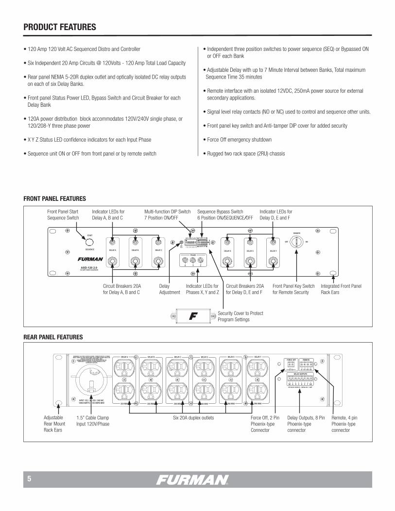
Front Panel Key Switch for Remote Security
Front Panel Start Sequence Switch
Circuit Breakers 20Afor Delay A, B and C
Delay Adjustment
Multi-function DIP Switch7 Position ON/OFF
Sequence Bypass Switch 6 Position ON/SEQUENCE/OFF
Integrated Front Panel Rack Ears
Indicator LEDs for Delay A, B and C
Indicator LEDs for Delay D, E and F
Indicator LEDs for Phases X, Y and Z
Circuit Breakers 20Afor Delay D, E and F
START
SEQUENCE
REMOTE
DELAY A DELAY B DELAY C
PHASE
X Y Z
DELAY D DELAY E DELAY F
OFF ON
ASD-120 2.0120 AMP POWER SEQUENCER
Security Cover to Protect Program Settings
1.5” Cable ClampInput 120V/Phase
Six 20A duplex outlets Force Off, 2 Pin Phoenix-type Connector
Remote, 4 pin Phoenix-type connector
Delay Outputs, 8 Pin Phoenix-type connector
FRONT PANEL FEATURES
REAR PANEL FEATURES
PRODUCT FEATURES
• 120 Amp 120 Volt AC Sequenced Distro and Controller
• Six Independent 20 Amp Circuits @ 120Volts - 120 Amp Total Load Capacity • Rear panel NEMA 5-20R duplex outlet and optically isolated DC relay outputs on each of six Delay Banks.
• Front panel Status Power LED, Bypass Switch and Circuit Breaker for each Delay Bank • 120A power distribution block accommodates 120V/240V single phase, or 120/208-Y three phase power
• X Y Z Status LED confidence indicators for each Input Phase
• Sequence unit ON or OFF from front panel or by remote switch
• Independent three position switches to power sequence (SEQ) or Bypassed ON or OFF each Bank
• Adjustable Delay with up to 7 Minute Interval between Banks, Total maximum Sequence Time 35 minutes
• Remote interface with an isolated 12VDC, 250mA power source for external secondary applications.
• Signal level relay contacts (NO or NC) used to control and sequence other units.
• Front panel key switch and Anti-tamper DIP cover for added security
• Force Off emergency shutdown
• Rugged two rack space (2RU) chassis
AdjustableRear Mount Rack Ears
6
The ASD-120 2.0 has a host of features and options that will be highlighted in this manual.
Here is a quick overview:
The ASD-120 2.0 can be thought of as an array of six high current relays that op-erate under the control of a microprocessor. The six relays (referred to as DELAY A through DELAY F) control the ON/OFF state of the power to six receptacles (also referred to as DELAY A through DELAY F) located on the rear panel. The ON or OFF state of each of the six receptacles is indicated by a series of six green status LEDs on the front panel. There are a series of six circuit breakers located on the front panel (underneath the status LEDs) that protect the loads connected to each of the receptacles, DELAY A through DELAY F. Finally, there are a series of six low power relays that operate in unison with the power switching relays. The contacts of these low power relays are available on the right side of the rear panel and allow the user to connect low voltage and low power devices to the ASD-120 2.0.
The ASD-120 2.0 has a rectangular security cover on the front panel. This cover can be removed to provide access to an array of switches that are used to con-figure the operation of the ASD-120 2.0. Details of these switches can be found later in this manual.
The basic operation of the ASD-120 2.0 can be described as follows:
Six individual Delay Banks feature a 120 Volt 20 Ampere AC circuit, and each AC circuit can be sequenced on or off with a programmable delay at set intervals. On/Off sequences can be initiated with ASD-120 2.0 front panel switches or a wired connection to the ASD-120 2.0 rear panel Remote interface. Each Delay Bank has one NEMA 5-20R duplex provided on the rear panel. In addition, any Delay Bank can be configured as Always On or Always Off independent from the sequence. The Delay Banks also have their own independent DC relay terminal for triggering other devices, including another ASD-120 2.0 or any Furman sequencing product.
The ASD-120 2.0 should be configured at time of installation. X Y Z Status LED indicators confirm the input phase of AC power. The configuration DIP switches are located behind a cover plate in the center of the front panel. A potentiometer is used to set delay timing intervals. After the ASD-120 2.0 is configured, the cover plate prevents inadvertent changes and tampering. A locking switch with a removable key is provided for added security.
PRODUCT OVERVIEW
The ASD-120 2.0 can be used as a stand-alone unit or in combination with other Furman power distribution devices. The ASD-120 2.0 provides six sequenced 120V, 20A circuits for a total load power of 14.4kW. Higher levels of power can be achieved by connecting additional Furman sequencers or other power conditioning products, including additional ASD-120 2.0 units. Furman products provide a practical means of centralized control over an extensive network of power distribution and conditioning equipment. As most sound reinforcement professionals know, AC power sequencing is neces-sary because the majority of equipment damage occurs when devices are either powered up or powered down. In addition, power sequencing is needed whenever various kinds of equipment must be powered up or down in discrete groups, rather than simultaneously. Power sequencing allows equipment to be powered up and powered down in an orderly and time-delayed sequence.
In professional audio, power sequencing is used to prevent speaker “pop” in speaker cabinets, enclosures and line arrays. The “pop” is generated when audio sources are switched on or off while an amplifier is still “live” or energized. The activation of source (signal processing) equipment often creates a small spike of transient voltage. When this voltage is amplified by the amplifiers, the resulting “pop” can be deafening and can easily damage speaker voice-coils. The reverse or “power down” of signal processing equipment can create a similar effect as during power down many devices emit uncontrolled transients. Power down transients can result in speaker “pop” and damage speaker components as well. Because AC power sequencing prevents this universally unwanted and often costly circumstance, AC power sequencing is prudent. Power sequencing has the added benefit of preventing nuisance breaker trips by offsetting the in-rush current demands of connected equipment over time. It is not difficult to imagine the extreme current demand that would be placed upon a breaker if all connected loads were to be activated at the same time. Power se-quencing allows equipment to be sequenced on in discrete stages - which allows each device to power up and current demands to stabilize individually. Although each device will undergo its own in-rush current at power up, because these events occur over time, the stress placed upon the breaker is greatly reduced. For this reason, AC power sequencing is a reliable strategy for protecting event productions and electrical infrastructure.
Years ago Furman introduced the original ASD-120, along with a full line of power sequencers, to address the concerns outlined above. Furman power sequencing products have been used by professional audio experts in a multitude of applica-tions for decades. When conceiving the ASD-120 2.0, we listened intently to the voice of our customers and industry experts. We appreciate all of the feedback and believe that the ASD-120 2.0 delivers the power switching needs and wishes of all of our customers.

7
Start Sequence Button Switch
The Start Sequence button located on the left side of the front panel can be used for sequencing power up or power down. The “START SEQUENCE” button is only activated when the key switch is set to the “Remote” mode. The function of this switch depends on the position of DIP Switch 7 and the duration of time that the button is depressed. Please note, setting the key switch to ON defeats operation of the START SEQUENCE push button. Both the key switch and the START SEQUENCE button operate in either Maintained or Momentary mode.
START
SEQUENCE
FRONT PANEL CONFIGURATION & FEATURES
Other Furman products which have remote interfaces compatible with the ASD-120 2.0 are listed below. All of these products can be used with the new ASD-120 2.0 through low voltage DC control.
• Furman Contractor Series CN-1800S, CN-2400S, CN-15MP & CN-20MP • PowerPort & Legacy MiniPorts MP-15, MP-20, MP-15Q & MP-20Q • M-8S & Legacy Sequencers PS-8R, PS-PRO, PS-8R II & PS-PRO II • Original Furman ASD-120 & Powerlink • RS-1 & RS-2 Remote System Control Panels • The Furman PS-REL AC Relay Accessory
Note: The ASD-120 2.0 has no line cord or master breaker, and is designed to be wired to a single phase 120/240V source with 60 amps per phase capacity, or to a three phase 208 WYE source with at least 40 amps capacity per phase.
PHASE
X Y ZPhase Indicators:
The ASD-120 2.0 features a set of three phase indicators; X, Y, and Z that will illuminate green when the corresponding phase (X, Y, and Z) is receiving power. These are sometimes referred to as “confidence indicators” because when these lamps are illuminated, you can be confident that the ASD-120 2.0 is receiving power. Although three indicators are provided, all three indicators will only be illuminated when the unit is connected to 3-phase 208-WYE power. When using 240 split phase, only two of the only phase indicators (X and Y) will illuminate
Note: X Y Z Status LED indicators confirm AC power on each Input Phase.
Delay Bank Indicators:
The ASD-120 2.0 has six Delay Bank LED indicators that will illuminate green when the corresponding Delay Bank (A through F) has been activated. When a Delay Bank LED is OFF, the corresponding rear panel receptacle has not been activated. When all Delay Banks have sequenced ON, all of the Delay Bank LEDs should illuminate green. When all Delay Banks have sequenced OFF, all of the Delay Bank LEDs should be off.
Note that the Delay Bank LED indicators only indicate when a bank has been activated. The indicators do not guarantee that power is being delivered to the corresponding Delay Bank. If a Delay Bank breaker has been tripped, the Delay Bank LED indicator may still illuminate green even though power is not being delivered to the Delay Bank with an open breaker.
The Delay Bank LED indicators are also used to indicate when the ASD-120 2.0 has been disabled due to a FORCE OFF condition. When the ASD-120 2.0 is in FORCE OFF mode the Delay Bank LED indicators will flash on and off. More on FORCE OFF mode later…
Note: A front panel Delay Bank LED indicator confirms the active state of the AC duplex and its associated DC relay.
START
SEQUENCE
REMOTE
DLYADJ
DELAY A DELAY B DELAY C
PHASE
X Y Z
DELAY D DELAY E DELAY F
OFF ON
1 2 3 4 5 6 7
ASD-120 2.0120 AMP POWER SEQUENCER
(SEE COVER PLATE) ALWAYS ON
ALWAYS OFF
SEQ
START
SEQUENCE
REMOTE
DLYADJ
DELAY A DELAY B DELAY C
PHASE
X Y Z
DELAY D DELAY E DELAY F
OFF ON
1 2 3 4 5 6 7
ASD-120 2.0120 AMP POWER SEQUENCER
(SEE COVER PLATE) ALWAYS ON
ALWAYS OFF
SEQ
START
SEQUENCE
REMOTE
DLYADJ
DELAY A DELAY B DELAY C
PHASE
X Y Z
DELAY D DELAY E DELAY F
OFF ON
1 2 3 4 5 6 7
ASD-120 2.0120 AMP POWER SEQUENCER
(SEE COVER PLATE) ALWAYS ON
ALWAYS OFF
SEQ
The ASD-120 2.0 Remote interface located at the rear panel provides a great deal of flexibility. The ASD-120 2.0 can be configured to command or respond to other controller-type equipment via low voltage DC impulses. If configured as a remotely controlled power source, the ASD-120 2.0 can respond to continuous maintained or momentary contact closures, open contacts, or the presence or absence of external DC voltage. At the same time, maintained control signals can be generated by the ASD-120 2.0 triggering connected equipment into or out of operation. Low level DC relay contacts A through F on each Delay Bank provide the means for external control of equipment associated with each AC circuit Delay Bank.
Installation is simplified by the unit’s 19 inch rack-mount design and hidden rear rack-mount ears. This feature is found alongside an industry standard 2RU chassis. The hidden rear mounts are adjustable.
Once installed and configured, you may expect years of trouble-free operation from the ASD-120 2.0. If during the service life of the product a question or issue may arise, please welcome our assistance and contact Furman. The unit is backed by a three year manufacturer’s warranty detailed on page 22 of this manual.

20 Amp Thermal Circuit Breakers
The ASD-120 2.0 has six, 20 Amp thermal circuit breakers that protect each of the six individual Delay Banks (A through F). The circuit breakers are located on the front panel immediately below the Bank Status LEDs. Each of the six circuit breakers (A through F) correspond to a Delay Bank (A through F)
If the combined current level plugged into a Delay Bank exceeds 20 Amps at any time, the circuit breaker will “trip”, the circuit breaker button will pop outward, and power will be cut to the devices connected to that particular Delay Bank.
If a breaker “trips” the user should review the load that is connected to the offending Delay Bank and make adjustments as necessary to reduce load to below 20A. To reset the breaker simply press the button in. Please note that the breakers are thermally activated. It is best to wait a few minutes to allow the breaker to cool before attempting to reset it.
8
ON
DIP SETTINGS
DLYADJ 1 2 3 4 5 6 7
ALWAYS ON
ALWAYS OFF
SEQ
SET TO MIDDLE POSITION
REMOTE
OFF ON
Key Switch - 3 position ON/OFF Security Switch
The ASD-120 2.0 has a three position key switch that functions as a Local ON Local OFF, and Remote interface selection switch. When the key is in the ON po-sition, the ASD-120 2.0 will sequence all Delay Banks on and remain on. When the key is in the OFF position, the ASD-120 2.0 will sequence all Delay Banks OFF and remain off. When the key is in the REMOTE position the ASD-120 2.0 will operate according to the signal presented at the remote interface and the action of the front panel START SEQUENCE button. If the key switch is in the REMOTE position and no signal is presented on the rear panel Remote interface, the ASD-120 2.0 will operate according to the front panel START SEQUENCE button. If the DELAY BANKS are off, pressing the START SEQUENCE button will cause the DELAY BANKS to sequence on. If the DELAY BANKS are on, pressing the START SEQUENCE button will cause the DELAY BANKS to squence off. If the key switch is rotated from REMOTE to the ON or OFF position, the ASD-120 2.0 will sequence ON or OFF according to the final position of the key switch.
When the key switch is in the REMOTE position, the ASD-120 2.0 can accept on/off commands from the rear panel 4-Pin Remote interface. The operation of the remote interface is explained elsewhere in this manual. Please note that the ON or OFF key switch positions defeat the rear panel remote interface.
ON: ON: Banks sequence ON and remain ON except those configured as “ALWAYS OFF” with the bypass switch.
OFF: Banks sequence OFF and remain OFF except those configured as “ALWAYS ON” with the bypass switch.
REMOTE: Accepts On/Off signals through the rear panel REMOTE connector and the front panel START SEQUENCE push-button switch.
Security Cover Shield and DIP Switch Program Interface
The ASD-120 2.0 had two configuration DIP switches that are located underneath a security cover near the center of the front panel. The two DIP switches are used to set various sequencer options. You will need a small Philips screwdriver to remove two 6-32 3/8” Philips screws to gain access to these switches.
The ASD-120 2.0 comes with the security cover pre-installed to protect against unauthorized configuration changes. The security cover is intended to discourage unauthorized personnel from tampering with or adjusting set programming once the unit has been installed. The security cover is attached to the front panel using two 6-32 3/8” Philips head screws. Please use only the two screws provided for attaching the security cover.
Note: Other types of tamper-resistant screws may be preferable depending on the desired level of security. Please do not exeed the 3/8” length restriction.
The Sequence Bypass DIP Switches
The ASD-120 2.0 has a six-position, three-state DIP switch located under the security cover on the front panel to the right of the multi – function DIP switch. The sequence bypass switch is used to bypass the sequencing on any or all of the DELAY BANKS. The sequence bypass switch is an array of six tri-state switches, and each tri-state switch has three possible positions (ON. OFF, and SEQUENCE).
When the switch is set to the ON (“Always On”) position, the corresponding DELAY BANK will be ON regardless of the state of the sequencer. When the switch is set to the OFF (Always Off”) position, the corresponding DELAY BANK will be OFF regardless of the state of the sequencer. When the switch is set to SEQ (“Sequence”), the corresponding DELAY BANK will follow the state of the sequencer.
Note that FORCE OFF mode has priority over the sequence bypass DIP switches. When the ASD-120 2.0 is in FORCE OFF mode, all banks will be disabled regard-less of the state of the sequence bypass DIP switches.
DIP position ON (A thru F) = Delay Bank and Relay is ALWAYS ONDIP position SEQ (A thru F) = Delay Bank and Relay activates in SequenceDIP position OFF (A thru F) = Delay Bank and Relay is ALWAYS OFF
Note: Except for a Force Off condition, the Sequence Bypass DIP Switch overrides any local or remote switch function.
START
SEQUENCE
REMOTE
DLYADJ
DELAY A DELAY B DELAY C
PHASE
X Y Z
DELAY D DELAY E DELAY F
OFF ON
1 2 3 4 5 6 7
ASD-120 2.0120 AMP POWER SEQUENCER
(SEE COVER PLATE) ALWAYS ON
ALWAYS OFF
SEQ
START
SEQUENCE
REMOTE
DLYADJ
DELAY A DELAY B DELAY C
PHASE
X Y Z
DELAY D DELAY E DELAY F
OFF ON
1 2 3 4 5 6 7
ASD-120 2.0120 AMP POWER SEQUENCER
(SEE COVER PLATE) ALWAYS ON
ALWAYS OFF
SEQ
START
SEQUENCE
REMOTE
DLYADJ
DELAY A DELAY B DELAY C
PHASE
X Y Z
DELAY D DELAY E DELAY F
OFF ON
1 2 3 4 5 6 7
ASD-120 2.0120 AMP POWER SEQUENCER
(SEE COVER PLATE) ALWAYS ON
ALWAYS OFF
SEQ
1M 2M 4M N.O.N.C.
1 2 3 4 5 6 7
ONMOMMNT
GND ON
12V ON12V OFF
DELAY
9
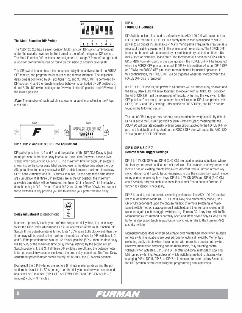
The Multi-Function DIP Switch
The ASD-120 2.0 has a seven-position Multi-Function DIP switch array located under the security cover on the front panel to the left of the bypass DIP switch. The Multi-Function DIP switches are designated 1 through 7 from left to right and a label for programming can be found on the inside of security cover plate.
This DIP switch is used to set the sequence delay time, active state of the FORCE OFF feature, and program the behavior of the remote interface. The sequence delay time is controlled by DIP positions 1, 2, and 3, FORCE OFF is controlled by DIP position 4, and the remote interface behavior is controlled by DIP positions 5, 6 and 7. The DIP switch settings are ON when in the UP position and OFF when in the DOWN position.
Note: The function of each switch is shown on a label located inside the F logo cover plate.
ON
DIP SETTINGS
DLYADJ 1 2 3 4 5 6 7
ALWAYS ON
ALWAYS OFF
SEQ
SET TO MIDDLE POSITION
ON
DIP SETTINGS
DLYADJ 1 2 3 4 5 6 7
ALWAYS ON
ALWAYS OFF
SEQ
SET TO MIDDLE POSITION
DIP 4, FORCE OFF Settings
DIP Switch position 4 is used to define how the ASD-120 2.0 will implement its FORCE OFF feature. FORCE OFF is a safety feature that is designed to cut AC power to all outlets instantaneously. Many municipalities require this feature as a means of disabling equipment in the presence of fire or alarm. The FORCE OFF inputs can be used with a momentary or maintained dry contact in either a Nor-mally Open or Normally Closed state. The factory default position is DIP 4 ON or UP, or (NO) Normally Open. In this configuration, the FORCE OFF will be triggered when the FORCE OFF pins are shorted. If DIP Switch position #4 is on (DIP 4 OFF or DOWN) the FORCE OFF pins must remain shorted for normal operation. In this configuration, the FORCE OFF will be triggered when the short between the FORCE OFF pins is removed.
If a FORCE OFF occurs, the power to all outputs will be immediately disabled and the Delay Bank LEDs will blink together. To recover from a FORCE OFF condition, the ASD-120 2.0 must be sequenced off locally, by turning the key swich to the OFF position. Once reset, normal operations will resume. DIP 4 has priority over DIP 5, DIP 6, and DIP 7 settings. Information on DIP 5, DIP 6, and DIP 7 can be found in the following section.
The use of DIP 4 may or may not be a consideration for every install. By default, DIP 4 is set to the ON (UP) position or (NO) Normally Open; meaning that the ASD-120 will operate normally with an open circuit applied to the FORCE OFF in-put. In this default setting, shorting the FORCE OFF pins will cause the ASD-120 2.0 to go into FORCE OFF mode.
DIP 1, DIP 2, and DIP 3: DIP Time Adjustment
DIP switch positions 1, 2 and 3 and the position of the DLY ADJ (Delay Adjust-ment) pot control the time delay interval or “dwell time” between consecutive stages when sequencing ON or OFF. The maximum time for each DIP switch is shown inside the cover plate label and represents the delay time when the DLY ADJ potentiometer is fully clockwise. DIP 1 adds 1 minute maximum time delay, DIP 2 adds 2 minutes and DIP 3 adds 4 minutes. Please note these time delays are cumulative. If all three DIP switches are in the UP position, the maximum allowable time delay will be 7minutes, i.e. 1min+2min+4min=7min. The factory default setting is DIP 1 ON or UP, and DIP 2 and 3 are OFF or DOWN. You can set these switches in any position you like to achieve your preferred time delay.
Delay Adjustment (potentiometer)
In order to precisely dial in your preferred sequence delay time, it is necessary to set the Time Delay Adjustment (DLY ADJ) located left of the multi-function DIP Switch. If this potentiometer is turned to its 100% value (fully clockwise), then the time delay will be equal to the maximum time delay defined by DIP switches 1, 2, and 3. If the potentiometer is in the 12 o’clock position (50%), then the time delay will be 50% of the maximum time delay interval defined by the setting of DIP Switch positions 1, 2 & 3. If all three DIP switches are off, and the potentiometer is turned completely counter-clockwise, the time delay is minimal. The Time Delay Adjustment potentiometer comes factory-set at 50%, the 12 o’clock position.
Example: If the DIP Switches are set to a 6 minute maximum delay and the po-tentiometer is set to its 50% setting, then the delay interval between sequenced banks will be 3 minutes. (DIP 1 OFF or DOWN, DIP 2 and DIP 3 ON or UP = 6 minutes) x .50 = 3 minutes.
1M 2M 4MN.O.N.C.
1 2 3 4 5 6 7
ON
MOMMNT
GND ON
12V ON12V OFF
DELAY
1M 2M 4MN.O.N.C.
1 2 3 4 5 6 7
ON
MOMMNT
GND ON
12V ON12V OFF
DELAY
Front Back
DIP 5, DIP 6 & DIP 7 Remote Mode Trigger Settings
DIP 5 (+12V, ON OFF) and DIP 6 (GND ON) are used in special situations, where the factory-set remote options are not preferred. For instance, a newly remodeled location has an existing remote key switch different from a Furman remote key switch design, and it would be advantageous to use the existing key switch, since many personnel already have keys. DIP 5 (+12V, ON OFF) and DIP 6 (GND ON) could possibly address such situations. Please feel free to contact Furman, if further assistance is necessary.
DIP 7 is used to set the remote switching preference. The ASD-120 2.0 can be set to a Maintained Mode (DIP 7 OFF or DOWN) or a Momentary Mode (DIP 7 ON or UP) dependent upon the chosen method of remote switching. A Main-tained switch method stays open until switched, and then remains closed until switched again (such as toggle switches, e.g. Furman RS-1 key lock switch).The Momentary switch method is normally open and stays closed only as long as the button is depressed (such as pushbutton switches, similar to the Furman RS-2 security switch).
Momentary Mode does offer an advantage over Maintained Mode when multiple remote switching locations are desired. Due to technical flexibility, Momentary switching easily adapts when implemented with more than one remote switch. However, maintained switching can be more stable, truly shunting control voltages when actuated. DIP 5 and DIP 6 offer additional methods of applying Maintained switching. Regardless of which switching method is chosen, when changing DIP 4, DIP 5, DIP 6, or DIP 7, it is required to reset the Key Switch to the OFF position before continuing the programming and installation.
10
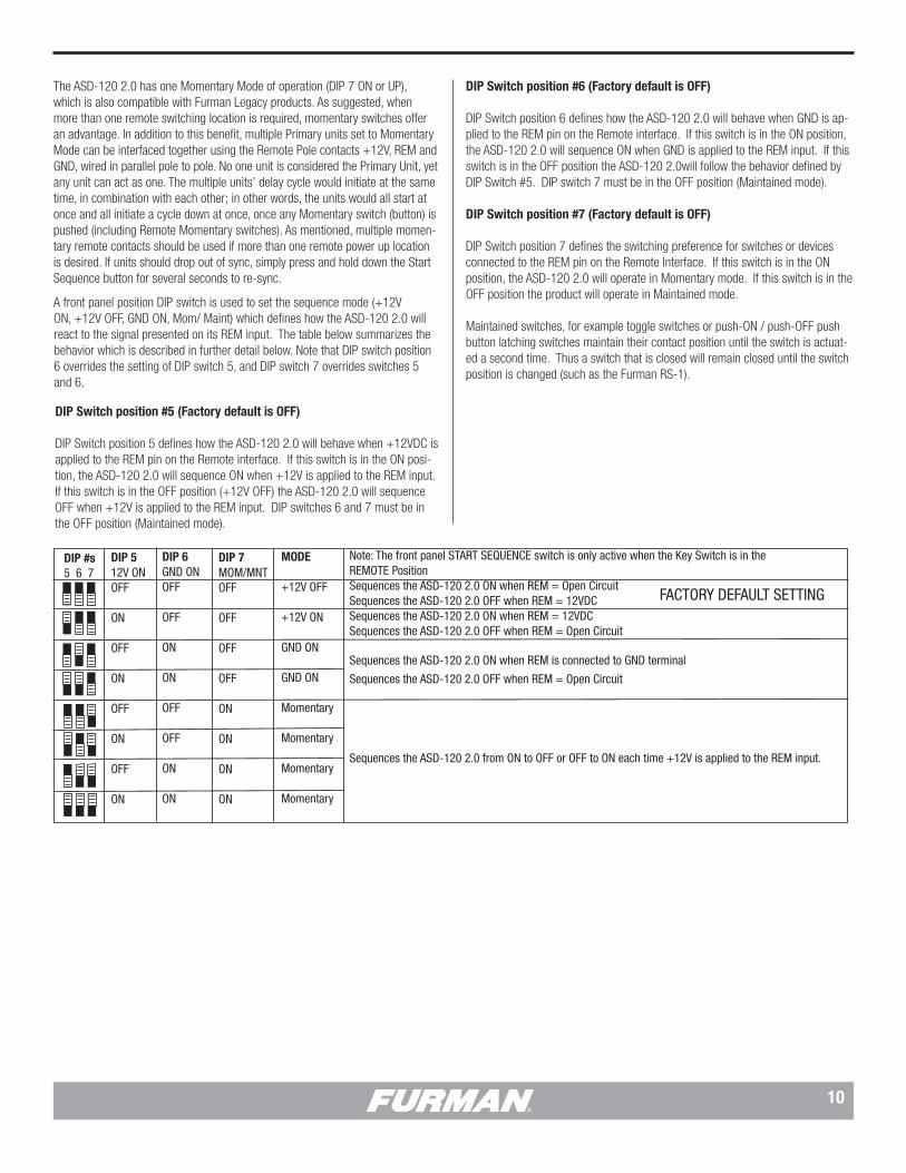
DIP Switch position #6 (Factory default is OFF)
DIP Switch position 6 defines how the ASD-120 2.0 will behave when GND is ap-plied to the REM pin on the Remote interface. If this switch is in the ON position, the ASD-120 2.0 will sequence ON when GND is applied to the REM input. If this switch is in the OFF position the ASD-120 2.0will follow the behavior defined by DIP Switch #5. DIP switch 7 must be in the OFF position (Maintained mode).
DIP Switch position #7 (Factory default is OFF)
DIP Switch position 7 defines the switching preference for switches or devices connected to the REM pin on the Remote Interface. If this switch is in the ON position, the ASD-120 2.0 will operate in Momentary mode. If this switch is in the OFF position the product will operate in Maintained mode.
Maintained switches, for example toggle switches or push-ON / push-OFF push button latching switches maintain their contact position until the switch is actuat-ed a second time. Thus a switch that is closed will remain closed until the switch position is changed (such as the Furman RS-1).
The ASD-120 2.0 has one Momentary Mode of operation (DIP 7 ON or UP), which is also compatible with Furman Legacy products. As suggested, when more than one remote switching location is required, momentary switches offer an advantage. In addition to this benefit, multiple Primary units set to Momentary Mode can be interfaced together using the Remote Pole contacts +12V, REM and GND, wired in parallel pole to pole. No one unit is considered the Primary Unit, yet any unit can act as one. The multiple units’ delay cycle would initiate at the same time, in combination with each other; in other words, the units would all start at once and all initiate a cycle down at once, once any Momentary switch (button) is pushed (including Remote Momentary switches). As mentioned, multiple momen-tary remote contacts should be used if more than one remote power up location is desired. If units should drop out of sync, simply press and hold down the Start Sequence button for several seconds to re-sync.
A front panel position DIP switch is used to set the sequence mode (+12V ON, +12V OFF, GND ON, Mom/ Maint) which defines how the ASD-120 2.0 will react to the signal presented on its REM input. The table below summarizes the behavior which is described in further detail below. Note that DIP switch position 6 overrides the setting of DIP switch 5, and DIP switch 7 overrides switches 5 and 6.
Note: The front panel START SEQUENCE switch is only active when the Key Switch is in the REMOTE PositionSequences the ASD-120 2.0 ON when REM = Open CircuitSequences the ASD-120 2.0 OFF when REM = 12VDCSequences the ASD-120 2.0 ON when REM = 12VDCSequences the ASD-120 2.0 OFF when REM = Open Circuit
Sequences the ASD-120 2.0 ON when REM is connected to GND terminal
Sequences the ASD-120 2.0 OFF when REM = Open Circuit
Sequences the ASD-120 2.0 from ON to OFF or OFF to ON each time +12V is applied to the REM input.
DIP 512V ONOFF
ON
OFF
ON
OFF
ON
OFF
ON
DIP 6GND ONOFF
OFF
ON
ON
OFF
OFF
ON
ON
DIP 7MOM/MNTOFF
OFF
OFF
OFF
ON
ON
ON
ON
MODE
+12V OFF
+12V ON
GND ON
GND ON
Momentary
Momentary
Momentary
Momentary
DIP #s5 6 7
FACTORY DEFAULT SETTING
DIP Switch position #5 (Factory default is OFF)
DIP Switch position 5 defines how the ASD-120 2.0 will behave when +12VDC is applied to the REM pin on the Remote interface. If this switch is in the ON posi-tion, the ASD-120 2.0 will sequence ON when +12V is applied to the REM input. If this switch is in the OFF position (+12V OFF) the ASD-120 2.0 will sequence OFF when +12V is applied to the REM input. DIP switches 6 and 7 must be in the OFF position (Maintained mode).

11
Note: When programming a new configuration it is recommended to start with the front panel Key Switch in the OFF position.
Multi-Function DIP Switch
• DIP 1 1M = 1 Minute Delay• DIP 2 2M = 2 Minute Delay• DIP 3 4M = 4 Minute Delay
Note: DIP 1, 2 and 3 sum together for a total sequence time of 35 minutes.
• DIP 4 N.O. / N.C. sets the active state of the FORCED OFF inputThe factory default setting for FORCED OFF is “ON” or “normally open”. In this mode, FORCE OFF is triggered when the FORCE OFF pins are shorted.
Note: If FORCED OFF mode is triggered ASD-120 2.0 will be disabled until FORCE OFF state is cleared by resetting Key Switch to OFF.
Note: Force Off overrides the Sequence Bypass DIP Switch and all Delay Bank LED indicators will flash.
• DIP 5 12VDC ON sets +12V Remote Mode
The factory default setting for 12VDC ON is “OFF” or disabled. If 12VDC ON is set to ON, the ASD-120 2.0 will sequence ON if 12VDC is applied to the remote pin on the remote interface.
12V OFF = 12VDC to REM deactivates12V ON = 12VDC to REM activates
Note: Factory Default is MAINTAINED ON Mode with DIP 5 set down to 12V OFF.
• DIP 6 GROUND ONThe factory default setting for GND ON is “OFF”. If this switch is changed to the “ON” position, the ASD-120 2.0 will sequence ON when GND is applied to the remote pin on the remote interface.
REM to GND = ON
Note: To disable the front panel button completely, the GND ON Maintained Mode should be used.
Note: GROUND ON mode overrides DIP 5.
ASD-120 2.0 PROGRAMMING SUMMARY
• DIP 7 MOM / MNT - Momentary / Maintained Sets local mode and remote contact closure preference for either Momentary or Maintained switches.
Note: Momentary mode overrides DIP 5 and 6.
Sequence Bypass DIP Switch
• DIP position ON (A thru F) = Delay Bank and Relay is ALWAYS ON• DIP position SEQ (A thru F) = Delay Bank and Relay activates in Sequence• DIP position OFF (A thru F) = Delay Bank and Relay is ALWAYS OFF
Note: Except for a Force Off condition, the Sequence Bypass DIP Switch overrides any local or remote switch function.
Key Switch
• OFF = Banks sequence OFF except those configured as “ALWAYS ON” in the sequence bypass DIP switch.
• REMOTE = Accepts On/Off signals through the rear panel REMOTE connector and the Start Sequence button.
• ON = Banks sequence ON except those configured as “ALWAYS OFF” in the sequence bypass DIP switch.
Note: The Start Sequence Button is disabled when DIP 6 is in GND ON mode (Position UP).
Note: Loss of AC Power or utility interruption in Maintained Mode will result in all Banks returning to the previous state when the utility service is restored. Main-tained On, Banks will return to ON. Maintained OFF, Banks will return to OFF. Note: Loss of AC Power or utility interruption in Momentary Mode will result in all Banks returning to an OFF state when the utility service is restored.
Note: If switch #4 on the Multi-Function DIP switch is set to OFF (NC Mode) the FORCE OFF pins on the rear panel must be shorted for normal operation. In NC Mode, a FORCE OFF condition will be triggered if the FORCE OFF pins are open circuit. The factory default is ON (NO Mode). In NO Mode, the ASD-120 2.0 functions normally with the FORCE OFF pins open circuit and FORCE OFF is triggered when FORCE OFF pins are shorted.

12
REAR PANEL CONTROL TERMINAL INTERFACE
DELAY OUTPUTS
NC A B C D E F NO
DRY RELAY CONTACTS - RATING 48V / 1 AMP
FORCE OFF
INPUT 120 / 3Ø, 208 / 240 VAC 14400 WATTS – 120 AMPS MAX 20A MAX
DELAY A
20A MAX
DELAY B
20A MAX
DELAY C
20A MAX
DELAY D
20A MAX
DELAY E
20A MAX
DELAY F
FORCE OFF
DELAY OUTPUTS
REMOTE
NC A B C D E F NO
12V STAT REM GND
WARNING! ELECTRIC SHOCK HAZARD. CONNECTION OF A POWER INPUT CABLE TO THIS DEVICE AND TO A POWER SOURCE MUST BE
DONE BY QUALIFIED PERSONNEL ONLY. DANGER: MANIPULER SEL ON LES INSTRUCTIONS DU
FABRICANT ET CONFIER LA MAINTENANCE A UN T ECHNICIEN QUALIFIE
DRY RELAY CONTACTS - RATING 48V / 1 AMP
FORCE OFF TERMINAL
The optically isolated FORCE OFF inputs are to be connected to a pair of dry switch contacts provided by an alarm or emergency kill switch. The ASD-120 2.0 will respond to NC or NO contacts based on the setting of DIP 4. All Delay Banks, including those configured as “Always On” will be powered off immediately when FORCE OFF is triggered. When triggered, all the Delay Bank LEDS will blink in unison while FORCE OFF state is active. The FORCE OFF input is designed with a 12VDC 10mA source for this purpose. To reset FORCE OFF, turn the Key Switch to the OFF position to clear the condition.
DELAY OUTPUTS TERMINAL The Delay Outputs are related to the activation of 6 relay contact. Each DC relay A thru F is activated when the corresponding Delay Bank and is switched ON. All outputs share a common connection at the left or right ends of this connector that will allow selection between normally closed (NC) or normally open (NO).
Note: The ASD-120 2.0 Remote interface is also compatible with other relay contact and low voltage DC control interfaces often used by other equipment brands and manufacturers.
PIN 1 +12VDC (12VDC Voltage Source)The +12VDC terminal pin is a general purpose, 12VDC voltage source relative to the GND (#4) pin. It is provided to allow the user to control the operation of the sequencer by feeding the +12VDC signal back into the REM terminal input; which is pin #3 on the same barrier strip.
PIN 2 STATUS (Output)The STAT (status) terminal is an output that may be used to activate an LED to indicate the status of the ASD-120 2.0. If the STAT terminal is high, the ASD-120 2.0 Delay outlets are either ON, or are in the process of sequencing ON. If the STAT terminal is low, the ASD-120 2.0 Delay outlets are OFF. To use the STAT terminal output simply connect an LED between the STAT and GND with the Cathode (flat) side of the LED oriented toward the GND pin (Pin #4). Do not use a series current limiting resistor. If the LED does not light when the remote switch is ON, check the polarity of the LED and reverse the leads if necessary.
• If the LED is OFF, the DELAY outputs are OFF• If the LED is ON, the DELAY outputs are ON• If the LED is blinking, the DELAY 1, 2 or 3 outputs are in transition either from ON to OFF or OFF to ON
PIN 3 REMOTE (Input)The REM (remote) terminal is provided to allow remotely connected devices to se-quence the ASD-120 2.0 ON or OFF. The ASD-120 2.0s’ REM terminal has been designed to work with voltages from 5 to 30VDC. Filtering has been added to this input to prevent false-triggering. The behavior of the ASD-120 2.0 is controlled by the combination of the signal presented at the REM terminal input, and the arrangement of the rear panel DIP switches. Please refer to FRONT PANEL DIP SWITCH section (page 9) for more details.
REMOTE
12V STAT REM GND
1 2 3 4
Remote Interface Pin Label Description
1 12V 12VDC @250mA General Purpose Output2 STAT Output for driving an external status LED3 REM Input for controlling the sequencer remotely4 GND Ground (12VDC Power and Signal Common)
NC
A
B
C
D
E
F
NG
RELAY A
RELAY B
RELAY C
RELAY D
RELAY E
RELAY F
REMOTE INTERFACEThe ASD-120 2.0 has a remote interface which can be used to control the ASD-120 2.0 remotely using a Furman RS-1 (Maintained) or RS-2 (Momentary) wall switches. In the most basic, single unit configuration, only two wires and a switch are required to initiate a remote ON or OFF sequence. The switch may be either a momentary or maintained-contact type. If a third & fourth wire are available, an LED “Status Light” can be installed at the remote switching location to indicate the status of the ASD-120 2.0. The pins on the remote interface are described below:
PIN 4 GND (Power)The GND (ground) terminal operate in unison with Delay A through F. GND can also be fed back into the REM pin (Pin #3) to activate the sequence when the ASD-120 2.0 has been configured for GND ON mode. Please note that the GND terminal on the Remote Interface is not the same as chassis ground and should never be connected to chassis ground.
The Delays outputs terminal conssist of a se-ries of six relays, internal to the ASD-120 2.0. These relays mirror the state of Delay Banks A through F. The diagram to the right shows how the relays are wired inside the ASD-120 2.0

13
ADVANCED INSTALLATION TOPICS
The beginning of the manual provides basic information for those who are familiar with Furman equipment. A more complete description of ASD-120 2.0 operations and configuration options are provided in the following sections.
Sequence Timing
Please note all Banks participate in the programmed time interval. The pro-grammed delay time will cycle through all Banks A thru F, regardless of a Bank’s assignment on the Bypass Switch. Banks that have been programmed as ALWAYS ON, or ALWAYS OFF experience no effect in the program timing, since bypassed Banks are independent of the ASD-120 2.0 control circuitry.
Note: The ASD-120 2.0 sequences each Delay Bank in order from A to F when sequencing ON, and turn Banks F to A OFF in the reverse order when sequenc-ing OFF. Triggers to initiate an ON or OFF sequence can occur at any time even during a programmed sequence. If triggered to do so, a unit’s programmed sequence will be and can be reversed at any time.
Sequence Initialization
Factory default mode for the ASD-120 2.0 is Maintained On. A sequence can oc-cur at any time, reverse at any time, and/or FORCED OFF at any time, even while a sequence is in progress. If Maintained Mode is configured and an SEQUENCE ON trigger is received while the Banks are On, nothing will happen. The same is true if all Delay Banks are OFF and a trigger to SEQUENCE OFF is received. There-fore if two or more remote switch locations are desired and the user would like to sequence ON or OFF from both locations. Momentary Mode and Momentary Switches must be employed. For example, if two Maintained switches are used and the Multi-Function Set is configured in Maintained On mode, the ASD-120 2.0 will remain ON until both remote locations are set to OFF.
A time-delayed On or Off sequence can be initiated at the front panel Key Switch, the START SEQUENCE button, or using the 4-Pin Remote Interface. The config-uration Multi-Function DIP switches can program a sequence response utilizing either Closed or Open Contacts, or the presence or absence of an external DC voltage (5 to 30VDC max). The following basic examples of remote integration are provided:
ON
DIP SETTINGS
1 2 3 4 5 6 7
ON
DIP SETTINGS
1 2 3 4 5 6 7
1. Key Switch and Start Sequence Button Control (Local and Remote Activation MAINTAINED ON). A sequence is initiated by turning the key switch past the REMOTE position to initiate a sequence ON or OFF.
A. DIP 7 set to (MNT) mode – DOWN Position Maintained Mode. B. Set DIP 5, DIP 6, and DIP 7 switches DOWN reserving DIP 1, DIP 2, and DIP 3 for delay timing. C. Turn Key Switch to the ON position for Local operation – Remove key if and when desired.
D. Or turn Key Switch to REMOTE position – Use Start Sequence button or a remote switch to initiate sequence.
E. Connect Maintained switch between REM and 12V at the REMOTE 4 Pin Connector (e.g. Furman RS-1).
Note: Start Sequence button on front panel is inoperative when the key switch is in the ON or OFF positions.
2. Start Sequence Button Control or Remote Push Button (Local and Remote MOMENTARY Operation)
When the front panel Key Switch is in the REMOTE position, the START SEQUENCING buttons can be used to toggle the sequence On or Off. A remote pushbutton such as the RS-2 momentary contact switch can be added to provide remote control as well:
A. Set Key Switch to the Remote position - Remove key if desired.
B. DIP 7 (MOM) in the UP position - Momentary operation is selected.
C. Set DIP 5 and DIP 6 switches DOWN reserving DIP 1, DIP 2, and DIP 3 for delay timing. D. Connect Push Button Momentary Switch between REM and 12V at the REMOTE 4 Pin Connector.
Note: Multiple Push Button Momentary Switches can be employed from multiple locations (e.g. Furman RS-2).
14
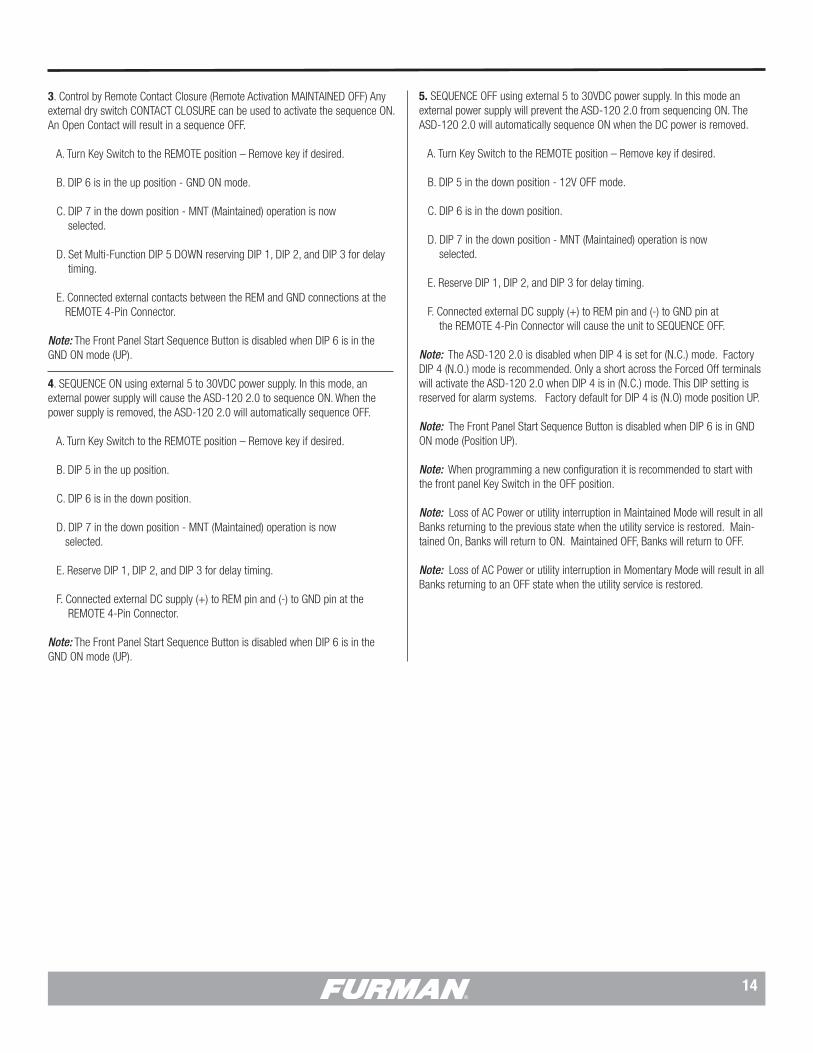
3. Control by Remote Contact Closure (Remote Activation MAINTAINED OFF) Any external dry switch CONTACT CLOSURE can be used to activate the sequence ON. An Open Contact will result in a sequence OFF.
A. Turn Key Switch to the REMOTE position – Remove key if desired.
B. DIP 6 is in the up position - GND ON mode.
C. DIP 7 in the down position - MNT (Maintained) operation is now selected.
D. Set Multi-Function DIP 5 DOWN reserving DIP 1, DIP 2, and DIP 3 for delay timing. E. Connected external contacts between the REM and GND connections at the REMOTE 4-Pin Connector.
Note: The Front Panel Start Sequence Button is disabled when DIP 6 is in the GND ON mode (UP).
4. SEQUENCE ON using external 5 to 30VDC power supply. In this mode, an external power supply will cause the ASD-120 2.0 to sequence ON. When the power supply is removed, the ASD-120 2.0 will automatically sequence OFF.
A. Turn Key Switch to the REMOTE position – Remove key if desired.
B. DIP 5 in the up position.
C. DIP 6 is in the down position.
D. DIP 7 in the down position - MNT (Maintained) operation is now selected.
E. Reserve DIP 1, DIP 2, and DIP 3 for delay timing. F. Connected external DC supply (+) to REM pin and (-) to GND pin at the REMOTE 4-Pin Connector.
Note: The Front Panel Start Sequence Button is disabled when DIP 6 is in the GND ON mode (UP).
5. SEQUENCE OFF using external 5 to 30VDC power supply. In this mode an external power supply will prevent the ASD-120 2.0 from sequencing ON. The ASD-120 2.0 will automatically sequence ON when the DC power is removed.
A. Turn Key Switch to the REMOTE position – Remove key if desired.
B. DIP 5 in the down position - 12V OFF mode.
C. DIP 6 is in the down position.
D. DIP 7 in the down position - MNT (Maintained) operation is now selected.
E. Reserve DIP 1, DIP 2, and DIP 3 for delay timing.
F. Connected external DC supply (+) to REM pin and (-) to GND pin at the REMOTE 4-Pin Connector will cause the unit to SEQUENCE OFF.
Note: The ASD-120 2.0 is disabled when DIP 4 is set for (N.C.) mode. Factory DIP 4 (N.O.) mode is recommended. Only a short across the Forced Off terminals will activate the ASD-120 2.0 when DIP 4 is in (N.C.) mode. This DIP setting is reserved for alarm systems. Factory default for DIP 4 is (N.O) mode position UP.
Note: The Front Panel Start Sequence Button is disabled when DIP 6 is in GND ON mode (Position UP).
Note: When programming a new configuration it is recommended to start with the front panel Key Switch in the OFF position.
Note: Loss of AC Power or utility interruption in Maintained Mode will result in all Banks returning to the previous state when the utility service is restored. Main-tained On, Banks will return to ON. Maintained OFF, Banks will return to OFF.
Note: Loss of AC Power or utility interruption in Momentary Mode will result in all Banks returning to an OFF state when the utility service is restored.

15
LOCAL AND REMOTE OPERATING MODES
Other configuration options are possible with an understanding of the REMOTE in-terface and configuration features of the ASD-120 2.0 discussed in the following sections.
Key Switch Control
Secured local control of the ASD-120 2.0 is best accomplished by using the front panel Key Switch. When in the ON position, all Delay Banks will sequence ON, except those configured with the Bypass Set as Always OFF. All Banks not configured as Always ON will be switched OFF once the Key Switch is returned to the OFF position. If the Key Switch is intended to be the primary control method, no external control connection to the rear panel REMOTE interface REM terminal is recommended, and DIP 6 should be set to the GND ON position (DIP 6 UP). In the absence of any external control signal, once the key switch has initially been rotated to the ON position and returned to the REMOTE position, the ASD-120 2.0 defaults to ON in either Maintained Mode or Momentary Mode.
Note:: The front panel Key Switch must be in the REMOTE position for ASD-120 2.0 to accept remote commands. Furthermore, an ON or an OFF key position set-ting functions in either DIP 7 Maintained or Momentary mode effectively bypasses all other command functions except the Bypass Set or a FORCE OFF condition.
Note: The Start Sequence Button is disabled when DIP 6 is in GND ON mode (Position UP).
Note: Loss of AC Power or utility interruption in Maintained Mode will result in all Banks returning to the previous programmed state when the utility service is restored. Maintained On, Banks will return to ON. Maintained OFF, Banks will return to OFF.
Note: Loss of AC Power or utility interruption in Momentary Mode will result in all Banks returning to an OFF state when the utility service is restored.
Front Panel Start Sequence Button Control
The ASD-120 2.0 front panel Start Sequence button can be used as the primary control to initiate a sequence. If the unit is programmed for Momentary Mode (DIP 7 = ON), each time Start Sequence is depressed, the ASD-120 2.0 will tog-gle between ON and OFF sequences. If the button is pressed and held for more than six seconds, the ASD-120 2.0 will sequence to the OFF state.
The front Start Sequence button should only be used when the Key Switch is in the REMOTE position with DIP 7 the MOM/MNT dip switch set to MOM (DIP 7 in the UP position).
Push buttons in multiple locations can be used to initiate ON/OFF sequences. Remote control options are discussed in the Momentary Mode Section.
Note: The Start Sequence Button is disabled when DIP 6 is in GND ON mode (Position UP).
Note: Loss of AC Power in Momentary Mode will result in all Banks returning to an OFF state when the utility service is restored.
Remote Operating Modes
When the Key Switch is in the REMOTE position, the ASD-120 2.0 will respond as configured by the switches behind the front panel cover plate. The ASD-120 2.0 can be programmed to respond to remote Momentary and sustained (Maintained) trigger conditions. The unit can be triggered by the presence or absence of contact closures or a DC voltage. The ASD-120 2.0 can also be used to trigger remote equipment using the same type of trigger conditions.
The ASD-120 2.0 and similar equipment (available from FURMAN and other sources) can be controlled in parallel with a control signal wired from a single switch. Also, control connections can be made in series with various units trig-gered from an event occurring at another piece of equipment. An infinite variety of connection schemes using any combination of these two methods is possible.
The momentary mode is only used with trigger signals that are of a short duration such as a push button. Equipment compatible with this type of trigger can be connected in a way that permits the initialization of a sequence from push buttons in multiple locations.
Signal level relay contacts A thru F are provided at the rear panel of the ASD-120 2.0 which can be used for the purpose of triggering external equipment. The contacts can be configured as a group as normally open (NO) or normally closed (NC).
When the key switch is in either the ON or OFF position, the ASD-120’s sequenc-ing circuits will not respond to the rear panel remote control inputs. If the key switch is returned to the REMOTE position, the signals supplied to the rear panel remote inputs will again control the unit.

16
Configuration for Remote Operation
Maintained switches are generally most convenient when there is only one remote control location. The ASD-120 2.0 is shipped factory-set for Maintained On operation. The alternate method of controlling the ASD-120 2.0 through the use of a momentary push button switches can be used when more than one remote switch location is required.
Note: The front panel Key Switch must be in the REMOTE position for ASD-120 2.0 to accept commands. Furthermore, an ON or an OFF key position functions in either DIP 7 Maintained or Momentary mode bypassing all other program functions except the Bypass Set or a Force Off condition.
Maintained On - 12V ON/OFF
When the Key Switch is in REMOTE mode, +12V present at the REM input with respect to GND will initiate an ON or OFF sequence depending on the position of DIP 5 (12V ON/12V OFF). After the sequence is complete, the output circuits will remain in the configured state as long as +12V is present. The source of the +12V can be from the remote interface itself, through remote relay contacts, or can be supplied by a +12V source from connected equipment. The absence of 12V will cause the ASD-120 2.0 to toggle, and remain in the opposite state.
The ASD-120 2.0 cannot operate in the 12V ON/OFF Maintained Mode when DIP 6 is set to the GND ON mode. The GND ON switch will take priority. In 12V ON/OFF Maintained Mode, one cannot use the START ON/OFF SEQUENCE button. If someone does press the button, the ASD-120 2.0, if ON, will start an OFF sequence that will last until you release the button.
Note: To disable the front panel button Start Sequence completely, the GND ON Maintained Mode should be used.
Maintained On - GND ON
A simple connection from the REM terminal to the GND will initiate an ON se-quence when DIP 6 is in the up position. After the sequence is complete, the output circuits will remain in the configured state as long as the ground con-nection to REM is present. Opening this connection initiates the OFF sequence. When DIP 6 is set for GND ON, the position of DIP 5 12V ON/OFF is ignored.
Note: The Start Sequence button has no effect when thw ASD-120 2.0 is in GND ON mode.
Maintained Off Mode
In the Maintained Off Mode, the ASD-120 2.0 will sequence ON or OFF with the Key Switch or a remote activation trigger. In this mode the ASD-120 2.0 will always remain in an OFF state until a connection is present between the REM and GND terminals or between the 12V and REM terminals.
DIP #7 switch is set in the down position (MNT) for operation in Maintained Mode. And when utilizing the REM and GND terminals, an ON response can be programmed by setting DIP switches #5 and #6 accordingly. And when utilizing the 12V and REM terminals, the same is true. The connection to the REMOTE interface must exist, whether it be a presence or absence of 12V or open/closed contacts. This mode is not typically used.
Note: The Start Sequence Button is disabled when DIP 6 is in GND ON mode (Position UP).
Momentary Mode
In the Momentary Mode, a momentary switch such as the one located on the front panel of the ASD-120 2.0, or the Furman RS-2 remote switch panel, can be used to initiate an ON or OFF sequence. The Momentary Mode is selected when DIP #7 (MOM/MNT) is in the up (MOM) position and DIP #6 (GND ON) is in the down position. The position of DIP #5 (12V ON/12V OFF) is ignored. In Momentary Mode, the ASD-120 2.0 will toggle between ON and OFF sequences every time a trigger is received from the front panel button or at the REM terminal with respect to GND. Multiple Furman devices with a REMOTE interface can be synchronized by connecting the REM and GND terminals together.
When the ASD-120 2.0 has been configured for momentary mode, the REM connection at the rear panel can act as an input or output depending on which button is pressed. If the ASD-120 2.0 button has been pushed, the REM connection provides a +12V output for as long as the button is depressed. Any connected Furman products with REM and GND terminals will also cycle on or off. To synchronize all equipment connected together in this way, press the START SEQUENCE button for at least 6 seconds. The outputs of all connected products will be shut off. If the connected product is a sequencer, the Sequence OFF will be triggered. If remotely triggered, the sequence starts on the rising edge of the signal at the REM terminal.
All Furman products connected in this way must be configured for Momentary Mode. When first plugged in (or after power is lost and reapplied for any reason), the ASD-120 2.0 outputs will remain off until a momentary trigger is received at the REM input or the START SEQUENCE button is pressed. Pressing the START SEQUENCE button while an ON or OFF sequence is in progress will result in an immediate change in direction of the sequence.
Note: Loss of AC Power in Momentary Mode will result in all Banks returning to an OFF state when the utility service is restored.
17
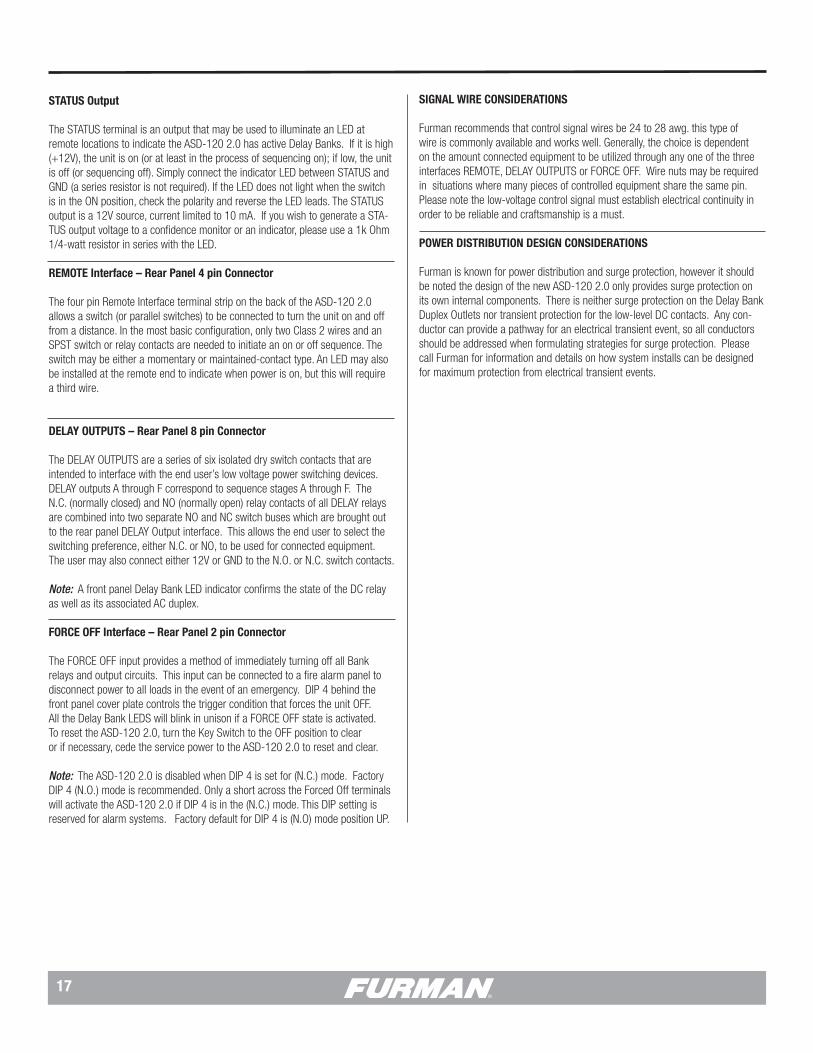
STATUS Output
The STATUS terminal is an output that may be used to illuminate an LED at remote locations to indicate the ASD-120 2.0 has active Delay Banks. If it is high (+12V), the unit is on (or at least in the process of sequencing on); if low, the unit is off (or sequencing off). Simply connect the indicator LED between STATUS and GND (a series resistor is not required). If the LED does not light when the switch is in the ON position, check the polarity and reverse the LED leads. The STATUS output is a 12V source, current limited to 10 mA. If you wish to generate a STA-TUS output voltage to a confidence monitor or an indicator, please use a 1k Ohm 1/4-watt resistor in series with the LED.
REMOTE Interface – Rear Panel 4 pin Connector
The four pin Remote Interface terminal strip on the back of the ASD-120 2.0 allows a switch (or parallel switches) to be connected to turn the unit on and off from a distance. In the most basic configuration, only two Class 2 wires and an SPST switch or relay contacts are needed to initiate an on or off sequence. The switch may be either a momentary or maintained-contact type. An LED may also be installed at the remote end to indicate when power is on, but this will require a third wire.
DELAY OUTPUTS – Rear Panel 8 pin Connector
The DELAY OUTPUTS are a series of six isolated dry switch contacts that are intended to interface with the end user’s low voltage power switching devices. DELAY outputs A through F correspond to sequence stages A through F. The N.C. (normally closed) and NO (normally open) relay contacts of all DELAY relays are combined into two separate NO and NC switch buses which are brought out to the rear panel DELAY Output interface. This allows the end user to select the switching preference, either N.C. or NO, to be used for connected equipment. The user may also connect either 12V or GND to the N.O. or N.C. switch contacts.
Note: A front panel Delay Bank LED indicator confirms the state of the DC relay as well as its associated AC duplex.
FORCE OFF Interface – Rear Panel 2 pin Connector
The FORCE OFF input provides a method of immediately turning off all Bank relays and output circuits. This input can be connected to a fire alarm panel to disconnect power to all loads in the event of an emergency. DIP 4 behind the front panel cover plate controls the trigger condition that forces the unit OFF. All the Delay Bank LEDS will blink in unison if a FORCE OFF state is activated. To reset the ASD-120 2.0, turn the Key Switch to the OFF position to clear or if necessary, cede the service power to the ASD-120 2.0 to reset and clear.
Note: The ASD-120 2.0 is disabled when DIP 4 is set for (N.C.) mode. Factory DIP 4 (N.O.) mode is recommended. Only a short across the Forced Off terminals will activate the ASD-120 2.0 if DIP 4 is in the (N.C.) mode. This DIP setting is reserved for alarm systems. Factory default for DIP 4 is (N.O) mode position UP.
SIGNAL WIRE CONSIDERATIONS
Furman recommends that control signal wires be 24 to 28 awg. this type of wire is commonly available and works well. Generally, the choice is dependent on the amount connected equipment to be utilized through any one of the three interfaces REMOTE, DELAY OUTPUTS or FORCE OFF. Wire nuts may be required in situations where many pieces of controlled equipment share the same pin. Please note the low-voltage control signal must establish electrical continuity in order to be reliable and craftsmanship is a must.
POWER DISTRIBUTION DESIGN CONSIDERATIONS
Furman is known for power distribution and surge protection, however it should be noted the design of the new ASD-120 2.0 only provides surge protection on its own internal components. There is neither surge protection on the Delay Bank Duplex Outlets nor transient protection for the low-level DC contacts. Any con-ductor can provide a pathway for an electrical transient event, so all conductors should be addressed when formulating strategies for surge protection. Please call Furman for information and details on how system installs can be designed for maximum protection from electrical transient events.

18
PRODUCT INSTALLATION EXAMPLES
ASD-120 2.0 ACTIVATED BY MULTIPLE RS-2 REMOTE SWITCH LOCATIONS WITH ONE PRIMARY SWITCH AND FIRE ALARM
ON
ASD-120 2.0 DIP SETTINGS
FIRE ALARM
DLYADJ 1 2 3 4 5 6 7
ALWAYS ON
ALWAYS OFF
SEQ
SET TO MIDDLE POSITION
12V STAT REM GND
12V STAT REM GND
ASD-120 2.0
PRIMARY SWITCH RS-2LOCATION #1
JUMPER J-2 ON
RS-2LOCATION #2
FORCE
NO
C
NC
RS-2 LOCATION #3
12V
STAT
REM
GND
12V
STAT
REM
GND
ASD-120 2.0
Diagram #2 illustrates multiple Furman RS-2 Remote System Control Panels controlling the ASD-120 2.0 sequencer while one RS-2 Remote System Control Panel acts as the Primary Security Key Switch:
1. All RS-2 terminal locations are connected to the ASD-120 2.0 REMOTE terminals, pole to pole: • 12V to 12V, REM to REM, STAT to STAT, and GND to GND.
2. Dedicate a single RS-2 as a Primary Switch. • Set J-2 jumper location, place suitcase jumper across both pins. • When this Primary RS-2 Key Switch is set in “DISABLED” location all other parallel connected RS-2 Remote System Control Panels “buttons” will be disabled. 3. Configure ASD-120 2.0 Multi-Function DIP for Normally Closed & Momentary Mode. • DIP 4 UP – (NO), verify factory default. • DIP 7 UP – MOM, verify Momentary Mode. • Configure 2.0 Multi-Function DIP switches 1, 2 & 3 to desired delay time interval. • Ensure All Bypass Set DIP switches are selected as desired. • Set ASD-120 2.0 Key Switch to Remote.
All RS-2 Remote System Control Panel or Momentary locations will activate the ASD-120 2.0 program sequence. The Primary RS-2 Remote System Control Panel has priority over the other control panels. When the key switch of the Primary RS-2 is set to the “DISABLED” position the operation of the other RS-2 Control Panel locations will be defeated.
M-8S WITH ASD-120 2.0
ON
ASD-120 2.0 DIP SETTINGS
DLYADJ 1 2 3 4 5 6 7
ALWAYS ON
ALWAYS OFF
SEQ
SET TO MIDDLE POSITION
FORCE
RS-1 REMOTE SWITCH
12V STAT REM GND
12V STAT REM GND
ASD-120 2.0 REMOTE PORT
12V ON12V OFF
GNDON
MOMMNT
DLYADJ
1 2 3 1
2
3
REMOTE PORT12V STAT REM GND
SECONDARY ASD-120 2.0
1. Configure ASD-120 2.0 Multi-Function DIP Switch Set for Normally Closed & Maintained Mode ON. • DIP 4 UP – (NO), verify factory default. • DIP 7 DOWN – MNT, verify factory default. • Configure ASD-120 2.0 Multi-Function DIP switches 1, 2 & 3 set for desired delay time. • Ensure All Bypass Set DIP switches are selected as desired. • Set ASD-120 2.0 Key Switch to Remote.
When the RS-1 remote switch is turned to ON it will trigger the ASD-120 2.0 to begin its sequence.
DIAGRAM EXAMPLE 1
DIAGRAM EXAMPLE 2
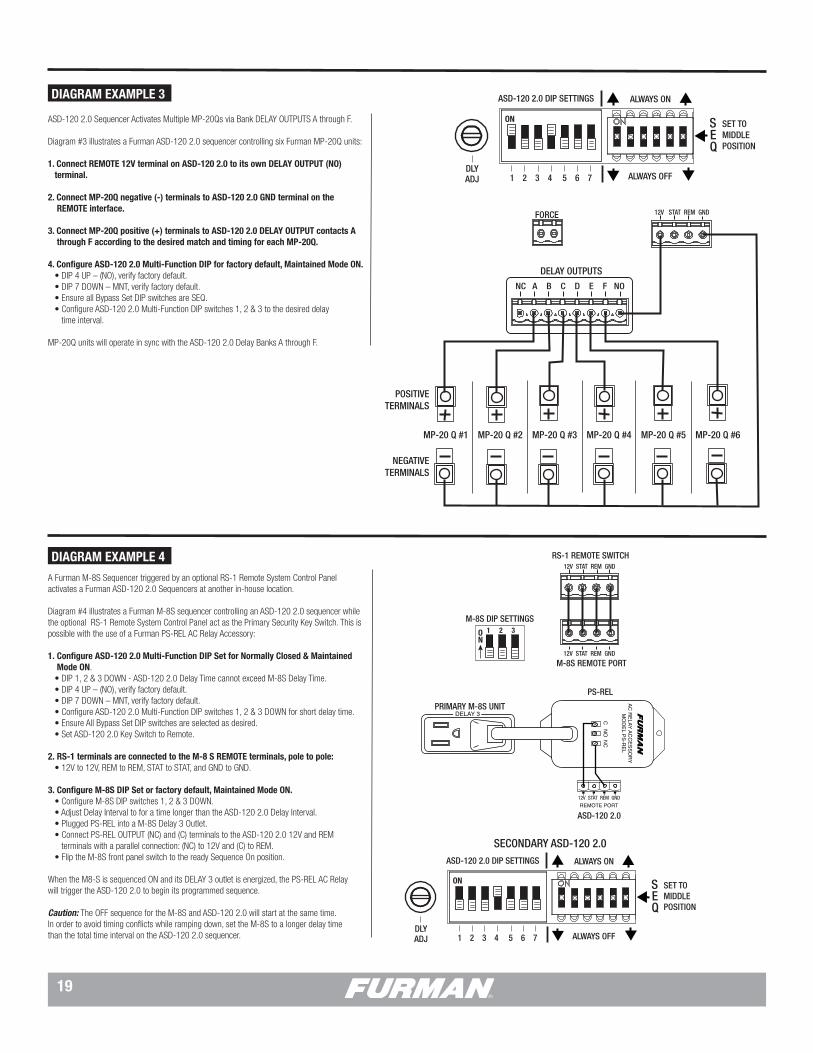
19
ASD-120 2.0 ACTIVATING MULTIPLE FURMAN MP-20 Q UNITS
ON
ASD-120 2.0 DIP SETTINGS
DLYADJ 1 2 3 4 5 6 7
ALWAYS ON
ALWAYS OFF
SEQ
SET TO MIDDLE POSITION
DELAY OUTPUTS
NC A B C D E F NO
12V STAT REM GNDFORCE
MP-20 Q #1 MP-20 Q #2 MP-20 Q #3 MP-20 Q #4 MP-20 Q #5 MP-20 Q #6
POSITIVETERMINALS
NEGATIVETERMINALS
M-8S WITH REMOTE SWITCH TRIGGERS ASD-120 2.0
ON
1 2 3ON
ASD-120 2.0 DIP SETTINGS
M-8S DIP SETTINGS
DLYADJ 1 2 3 4 5 6 7
ALWAYS ON
ALWAYS OFF
SEQ
SET TO MIDDLE POSITION
FORCE
RS-1 REMOTE SWITCH
12V STAT REM GND
12V STAT REM GND
M-8S REMOTE PORT
12V ON12V OFF
GNDON
MOMMNT
DLYADJ
1 2 3 1
2
3
REMOTE PORT12V STAT REM GND
DELAY 3
REMOTE PORT12V STAT REM GND
AC R
ELAY ACC
ESSORY
MO
DEL PS-R
EL
C N
O N
C
PS-REL
PRIMARY M-8S UNIT
SECONDARY ASD-120 2.0
ASD-120 2.0
ASD-120 2.0 Sequencer Activates Multiple MP-20Qs via Bank DELAY OUTPUTS A through F.
Diagram #3 illustrates a Furman ASD-120 2.0 sequencer controlling six Furman MP-20Q units:
1. Connect REMOTE 12V terminal on ASD-120 2.0 to its own DELAY OUTPUT (NO) terminal.
2. Connect MP-20Q negative (-) terminals to ASD-120 2.0 GND terminal on the REMOTE interface.
3. Connect MP-20Q positive (+) terminals to ASD-120 2.0 DELAY OUTPUT contacts A through F according to the desired match and timing for each MP-20Q. 4. Configure ASD-120 2.0 Multi-Function DIP for factory default, Maintained Mode ON. • DIP 4 UP – (NO), verify factory default. • DIP 7 DOWN – MNT, verify factory default. • Ensure all Bypass Set DIP switches are SEQ. • Configure ASD-120 2.0 Multi-Function DIP switches 1, 2 & 3 to the desired delay time interval.
MP-20Q units will operate in sync with the ASD-120 2.0 Delay Banks A through F.
Diagram Example #4
A Furman M-8S Sequencer triggered by an optional RS-1 Remote System Control Panel activates a Furman ASD-120 2.0 Sequencers at another in-house location.
Diagram #4 illustrates a Furman M-8S sequencer controlling an ASD-120 2.0 sequencer while the optional RS-1 Remote System Control Panel act as the Primary Security Key Switch. This is possible with the use of a Furman PS-REL AC Relay Accessory:
1. Configure ASD-120 2.0 Multi-Function DIP Set for Normally Closed & Maintained Mode ON. • DIP 1, 2 & 3 DOWN - ASD-120 2.0 Delay Time cannot exceed M-8S Delay Time. • DIP 4 UP – (NO), verify factory default. • DIP 7 DOWN – MNT, verify factory default. • Configure ASD-120 2.0 Multi-Function DIP switches 1, 2 & 3 DOWN for short delay time. • Ensure All Bypass Set DIP switches are selected as desired. • Set ASD-120 2.0 Key Switch to Remote.
2. RS-1 terminals are connected to the M-8 S REMOTE terminals, pole to pole: • 12V to 12V, REM to REM, STAT to STAT, and GND to GND.
3. Configure M-8S DIP Set or factory default, Maintained Mode ON. • Configure M-8S DIP switches 1, 2 & 3 DOWN. • Adjust Delay Interval to for a time longer than the ASD-120 2.0 Delay Interval. • Plugged PS-REL into a M-8S Delay 3 Outlet. • Connect PS-REL OUTPUT (NC) and (C) terminals to the ASD-120 2.0 12V and REM terminals with a parallel connection: (NC) to 12V and (C) to REM. • Flip the M-8S front panel switch to the ready Sequence On position.
When the M8-S is sequenced ON and its DELAY 3 outlet is energized, the PS-REL AC Relay will trigger the ASD-120 2.0 to begin its programmed sequence.
Caution: The OFF sequence for the M-8S and ASD-120 2.0 will start at the same time. In order to avoid timing conflicts while ramping down, set the M-8S to a longer delay time than the total time interval on the ASD-120 2.0 sequencer.
DIAGRAM EXAMPLE 3
DIAGRAM EXAMPLE 4

20
CN-2400S Controls two ASD-120 2.0 Sequencers with an optional Fire Alarm Force OFF.
Diagram #5 illustrates a Furman CN-2400S Contractor Series controlling two ASD-120 2.0 sequencers with a fire alarm providing an emergency FORCE OFF:
1. CN-2400 S DELAY 3 RELAY OUTPUT (NC) and (C) terminals connect appropriately to both ASD-120 2.0 units per the 12V and REM terminals with a parallel connection. • (NC) to both 12V and (C) to both REM.
2. Configure Multi-Function DIP on the CN-2400S, factory default with DIP 4 UP. • DIP 4 UP – (NO), verify factory default.◦ • CN-2400S DIP 2 is also set UP for a longer delay time.
3. Fire alarm contacts connected to FORCE OFF terminals on both ASD-120s (parallel connection). • Configure DIP 4 switch on ASD-120 2.0 to NO or NC depending on the contact type. used at the fire alarm. Typically NC is the best terminal option for Event Production. • Configure Multi-Function DIP on each ASD-120 2.0, factory default with DIP 4 UP. • All Delay Bank LED indicators will flash when FORCE OFF is activated. • Optionally, the fire alarm contacts can also be connected to the FORCE OFF terminals of the CN-2400 S if desired.
4. Configure ASD-120 2.0 Multi-Function DIP for Normally Closed & Maintained Mode ON. • DIP 4 UP – (NO), verify factory default. • DIP 7 DOWN – MNT, verify factory default. • ASD-120 2.0 DIP 1 is also set UP for a shorter delay time.
TWO ASD-120 2.0 UNITS CONTROLLED BY A CN-2400S AND BY FIRE ALARM
1 2 3 4 5 6 7
ON
1 2 3 4 5 6 7 8 9
ON
1 2 3 4 5 6 7 8 9
1 2 3 4 5 6 7
ON
FORCE OFF
DELAY 3
NO
NC
C
FO
FO
CN-2400S DIP SETTINGS
CN-2400S DIP SETTINGS
ASD-120 2.0 DIP SETTINGS
ASD-120 2.0 DIP SETTINGS
FIRE ALARM SYSTEM TRIGGER
+12V
STAT
REM
GND
REMOTE PORT
OPTIONAL REMOTE SWITCH
REMOTE
12V STAT REM GND
FORCE OFF
FORCE OFF
NOC
NC
REMOTE
12V STAT REM GND
When the CN-2400S is sequenced ON, the CN-2400S unit’s DELAY 3 Contact Relay will trigger both ASD-120 2.0 units to begin their respective programmed sequence.
Caution: The OFF sequence for the CN2400S and ASD-120 2.0 units will start at the same time. In order to avoid timing conflicts while ramping down, the CN-2400S should be set to a longer delay time interval than all the time intervals on each ASD-120 2.0 sequencer.
ASD-120 2.0 ADVANCED INSTALLATION WITH FURMAN CN SERIES AND REMOTE RS-1 SWITCH
ON
ONCN-2400S DIP SETTINGS
ASD-120 2.0 DIP SETTINGS
FIRE ALARM NO C NC
FORCE
REMOTE
12V STAT REM GND
12V STAT REM GND
DLYADJ 1 2 3 4 5 6 7
ALWAYS ON
ALWAYS OFF
SEQ
*SET TO MIDDLE POSITION
DELAY OUTPUTS
NC A B C D E F NO
12V 12V
REM
1 2 3 4 5 6 7 8 9
ONCN-2400S DIP SETTINGS
1 2 3 4 5 6 7 8 9
ONCN-20MP DIP SETTINGS
1 2 3 4 5 6 7 8 9
ONCN-20MP DIP SETTINGS
1 2 3 4 5 6 7 8 9
ONCN-20MP DIP SETTINGS
1 2 3 4 5 6 7 8 9
ONCN-20MP DIP SETTINGS
1 2 3 4 5 6 7 8 9
12V 12V 12V 12V
REM REM REM REM REM
Diagram Example #6
An ASD-120 2.0 Sequencer is controlled by a single RS-1 Remote System Control Panel and theASD-120 2.0 remotely activates Furman Contractor Series Products with Bank DELAY OUTPUTS A through F.
Diagram #6 illustrates a Furman ASD-120 2.0 sequencer controlling six Furman Contractor Series units and a fire alarm provides an optional FORCE OFF:
1. Connect CN-2400S and CN-20MP REM terminal pins to ASD-120 2.0 DELAY OUTPUT (NC).. 2. Connect a 12V terminal pin from each CN-2400S and CN-20MP to an appropriate A through F pin at the ASD-120 2.0 DELAY OUTPUT interface.
3. Configuration Multi-Function DIP on the CN-2400S units are factory default with DIP 4 UP. • Only DIP 1 is set DOWN for a shorter than ASD-120 2.0 delay time on each CN-2400S unit.
4. Configuration Multi-Function DIP on the CN-20MP units are factory default with DIP 4 UP. • Only DIP 1 is set DOWN for a shorter than ASD-120 2.0 delay time on each CN-20MP unit.
5. Optionally, a fire alarm can be connected to FORCE OFF at the ASD-120 2.0, if desired. • Configure Multi-Function DIP on the ASD-120 2.0, factory default with DIP 4 UP. • All Delay Bank LED indicators will flash when FORCE OFF is activated.
6. RS-1 terminals are connected to the ASD-120 2.0 REMOTE terminals, pole to pole: • 12V to 12V, REM to REM, STAT to STAT, and GND to GND.
7. Configure ASD-120 2.0 Multi-Function DIP for Normally Closed and Maintained Mode ON. • ASD-120 2.0 DIP 2 is set UP for a longer delay time than Contractor Series units. • DIP 4 UP – (NO), verify factory default. • DIP 7 DOWN – MNT, verify factory default. • Ensure all Bypass Set DIP switches are SEQ. • Set ASD-120 2.0 Key Switch to Remote.
ON/OFF Sequences are triggered by the RS-1 Key Switch or by the rotating the Key Switch to ON at the ASD-120 2.0 as an RS-1 override.
DIAGRAM EXAMPLE 5
DIAGRAM EXAMPLE 6
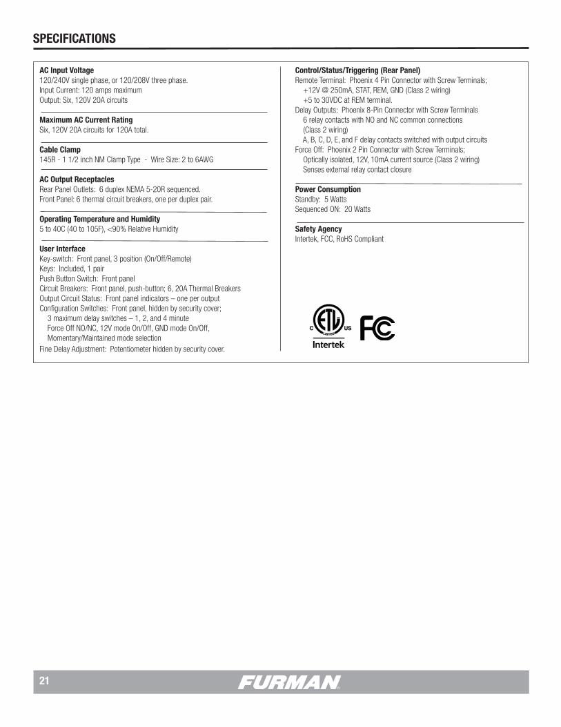
21
AC Input Voltage120/240V single phase, or 120/208V three phase.Input Current: 120 amps maximumOutput: Six, 120V 20A circuits
Maximum AC Current RatingSix, 120V 20A circuits for 120A total.
Cable Clamp145R - 1 1/2 inch NM Clamp Type - Wire Size: 2 to 6AWG
AC Output ReceptaclesRear Panel Outlets: 6 duplex NEMA 5-20R sequenced.Front Panel: 6 thermal circuit breakers, one per duplex pair.
Operating Temperature and Humidity5 to 40C (40 to 105F), <90% Relative Humidity
User InterfaceKey-switch: Front panel, 3 position (On/Off/Remote)Keys: Included, 1 pairPush Button Switch: Front panelCircuit Breakers: Front panel, push-button; 6, 20A Thermal BreakersOutput Circuit Status: Front panel indicators – one per outputConfiguration Switches: Front panel, hidden by security cover; 3 maximum delay switches – 1, 2, and 4 minute Force Off NO/NC, 12V mode On/Off, GND mode On/Off, Momentary/Maintained mode selectionFine Delay Adjustment: Potentiometer hidden by security cover.
SPECIFICATIONS
Control/Status/Triggering (Rear Panel)Remote Terminal: Phoenix 4 Pin Connector with Screw Terminals; +12V @ 250mA, STAT, REM, GND (Class 2 wiring) +5 to 30VDC at REM terminal.Delay Outputs: Phoenix 8-Pin Connector with Screw Terminals 6 relay contacts with NO and NC common connections (Class 2 wiring) A, B, C, D, E, and F delay contacts switched with output circuitsForce Off: Phoenix 2 Pin Connector with Screw Terminals; Optically isolated, 12V, 10mA current source (Class 2 wiring) Senses external relay contact closure
Power ConsumptionStandby: 5 WattsSequenced ON: 20 Watts
Safety AgencyIntertek, FCC, RoHS Compliant

22
3 YEAR LIMITED WARRANTY
PLEASE SAVE YOUR SALES RECEIPT! The receipt is your proof of purchase and confirms the product was purchased at an authorized Furman dealer. It will need to be submitted to Furman in order to process any warranty claims.
Furman, a brand of Core Brands LLC., warrants its ASD-120 2.0 (the “Product”) as follows:
Furman warrants to the original purchaser of the product that the product sold hereunder will be free from defects in material and workmanship for a period of three years from the date of purchase. If the product does not conform to this Limited Warranty during the warranty period (as herein above specified), purchaser shall notify Furman of the claimed defects by calling 800-472-5555 or via email ([email protected]). If the defects are of such type and nature as to be covered by this warranty, Furman shall authorize purchaser to return the product to Furman. Warranty claims MUST be accompanied by a copy of the original purchase invoice or receipt showing the purchase date. Shipping charges to Furman must be prepaid by the purchaser of the product. Furman shall, at its own expense, furnish a replacement product or, at Furman’s option, repair the defective product. Return shipping charges back to purchaser will be paid by Furman.
THE FOREGOING IS IN LIEU OF ALL OTHER WARRANTIES, EXPRESS OR IMPLIED, INCLUDING BUT NOT LIMITED TO THE IMPLIED
WARRANTIES OF MERCHANTABILITY AND FITNESS FOR A PARTICULAR PURPOSE.
Furman does not warrant against damages or defects arising out of improper use or abnormal handling of the product, or against defects or damages arising from improper installation. This warranty shall be cancelable by Furman at its sole discretion if the product is modified in any way without written authorization from Furman or Core Brands LLC. This warranty also does not apply to products upon which repairs have been affected or attempted by persons other than pursuant to written authorization by Furman or Core Brands LLC.
THIS WARRANTY IS EXCLUSIVE. The sole and exclusive obligation of Furman shall be to repair or replace the defective product in the manner and for the period provided above. Furman shall not have any other obligation with respect to the products or any part thereof, whether based on contract, tort, strict liability or otherwise. Under no circumstances, whether based on this Limited Warranty or otherwise, shall Furman be liable for incidental, special, or consequential dam-ages. This Limited Warranty states the entire obligation of Furman with respect to the product. If any part of this Limited Warranty is determined to be void or illegal, the remainder shall remain in full force and effect.
SERVICE
NOTE: All equipment being returned for repair must have an RMA (Return Mate-rials Authorization) number. To receive an RMA number, please contact Furman Technical Services at [email protected] or call, (800) 472-5555, between the hours of 6 a.m. and 4 p.m., U.S. Pacific Time. In order to issue an RMA number, Furman will require the Model and Serial Number of the product, your name, address, phone number, and a brief description of the problem. An email address, if available, will be helpful in expediting your RMA. If the unit is being returned for warranty service, further information may be required to substantiate the warranty status.
Please be sure that your RMA product is adequately packed and cushioned against damage in shipment. We suggest that you retain and use the original packaging to ship RMA materials for servicing. Furman assumes no liability for damages that occur during shipment. The RMA number should be prominently displayed on the shipping label or outside of the package. Please enclose a note with the RMA number, the Serial Number, your name, address, phone number and a brief description of the problem – failure to do so may delay diagnosis and repair
Furman Sound and Core Brands LLC. reserve the right to repackage and return repaired items using packaging materials deemed appropriate and suitable to for safe transit. Customer supplied materials, such as blankets, bubble wrap, packaging foam, and the like may be discarded if not suitable for shipment. Addi-tionally, professional containers such as Road/Flight Cases may be shipped back separately at the owner’s expense if Furman Technical Services determines that the Road / Flight Case is unsuitable for the safe return of the RMA Materials.
WARRANTY INFORMATION
CAUTION! WARRANTY LIMITATION FOR INTERNET PURCHASERS
Furman products purchased through the Internet do not carry a valid Product Warranty unless purchased from an Authorized Furman Internet Dealer and the original factory serial numbers are intact (they must not have been removed, defaced or replaced in any way). Purchasing from an Authorized Furman Internet Dealer insures that the product was intended for consumer use, has passed all quality inspections and is safe. Buying through auction sites or unauthorized deal-ers may result in the purchase of salvaged, failed and/or products not intended for use in the US. In addition, Authorized Furman Internet dealers have demon-strated sufficient expertise to insure warranty compliant installations. For a list of Authorized Furman Internet Dealers go to www.furmansound.com
Units under warranty shall be returned free of charge as stated in the Limited Warranty section of this manual. If you have any questions, please contact Furman Technical Services between 6 a.m. and 4 p.m., U.S. Pacific Time, 800-472-5555, or via email [email protected]

© 2015 Core Brands. All rights reserved. Furman is a registered trademark of Core Brands, a Nortek, Inc. Company
Furman • 1800 S. McDowell Blvd. • Petaluma, CA. 94954800-472-5555 • www.furmansound.com
10007825 REV. B ASD-120 2.0 INST. 10-15
Note: When programming a new configuration it is recommended to start with the front panel Key Switch in the OFF position.
Multi-Function DIP Switch
• DIP 1 1M = 1 Minute Delay• DIP 2 2M = 2 Minute Delay• DIP 3 4M = 4 Minute Delay
Note: DIP 1, 2 and 3 sum together for a total sequence time of 35 minutes.
• DIP 4 N.O. / N.C. sets the active state of the FORCED OFF inputThe factory default setting for FORCED OFF is “ON” or “normally open”. In this mode, FORCE OFF is triggered when the FORCE OFF pins are shorted.
Note: If FORCED OFF mode is triggered ASD-120 2.0 will be disabled until FORCE OFF state is cleared by resetting Key Switch to OFF.
Note: Force Off overrides the Sequence Bypass DIP Switch and all Delay Bank LED indicators will flash.
• DIP 5 12VDC ON sets +12V Remote Mode
The factory default setting for 12VDC ON is “OFF” or disabled. If 12VDC ON is set to ON, the ASD-120 2.0 will sequence ON if 12VDC is applied to the remote pin on the remote interface.
12V OFF = 12VDC to REM deactivates12V ON = 12VDC to REM activates
Note: Factory Default is MAINTAINED ON Mode with DIP 5 set down to 12V OFF.
• DIP 6 GROUND ON / OFFThe factory default setting for GND ON is “OFF”. If this switch is changed to the “ON” position, the ASD-120 2.0 will sequence ON when GND is applied to the remote pin on the remote interface.
REM to GND= ON with ShortREM to GND, +5V to 30VDC at REM + DIP 5 12V OFF = OFFREM to GND, +5V to 30VDC at REM + DIP 5 12V ON = ON
Note: To disable the front panel button completely, the GND ON Maintained Mode should be used.
Note: GND to REM pins should be used for remote triggers with applied DC voltages, +5V to 30VDC at REM.
ASD-120 2.0 PROGRAMMING SUMMARY
• DIP 7 MOM / MNT - Maintained / Momentary Sets local mode and remote contact closure preference for either Maintained or Momentary switches.
Note: Momentary mode overrides DIP 5 and 6.
Sequence Bypass DIP Switch
• DIP position ON (A thru F) = Delay Bank and Relay is ALWAYS ON• DIP position SEQ (A thru F) = Delay Bank and Relay activates in Sequence• DIP position OFF (A thru F) = Delay Bank and Relay is ALWAYS OFF
Note: Except for a Force Off condition, the Sequence Bypass DIP Switch overrides any local or remote switch function.
Key Switch
• OFF = Banks sequence OFF except those configured as “ALWAYS ON” in the sequence bypass DIP switch.
• REMOTE = Accepts On/Off signals through the rear panel REMOTE connector and the Start Sequence button.
• ON = Banks sequence ON except those configured as “ALWAYS OFF” in the sequence bypass DIP switch.
Note: The Start Sequence Button is disabled when DIP 6 is in GND ON mode (Position UP).
Note: Loss of AC Power or utility interruption in Maintained Mode will result in all Banks returning to the previous state when the utility service is restored. Main-tained On, Banks will return to ON. Maintained OFF, Banks will return to OFF. Note: Loss of AC Power or utility interruption in Momentary Mode will result in all Banks returning to an OFF state when the utility service is restored.
Note: If switch #4 on the Multi-Function DIP switch is set to OFF (N.C. Mode) the FORCE OFF pins on the rear panel must be shorted for normal operation. In N.C. Mode, a FORCE OFF condition will be triggered if the FORCE OFF pins are open circuit. The factory default is ON (N.O. Mode). In N.O. Mode, the ASD-120 2.0 functions normally with the FORCE OFF pins open circuit and FORCE OFF is triggered when FORCE OFF pins are shorted.