owner’s & installation manualafter reading this manual, keep it handy, such as in your glove...
TRANSCRIPT

6 CHANNEL AMPLIFIER
Owner’s & Installation manual

2 ADP6000
English
CLARION PRODUCT REGISTRATION INFORMATIONDear Customer:Congratulations on your purchase of a Clarion mobile electronic products. We are confident that you’ll enjoy your Clarion experience.There are many benefits to registering your product. We invite you to visit our website at www.clarion.com to register your Clarion product.We have made product registration simple with our easy to use website. The registration form is short and easy to complete. Once you’re registered, we can keep you informed of important product information.Register at www.clarion.com - it’s easy to keep your Clarion product up to date.
Thank you for purchasing this Clarion product. Please read the owner’s manual in its entirety before operating the equipment. After reading this manual, keep it handy, such as in your glove compartment. Save your sales receipt. The warranty at the end of this manual and your sales receipt are essential for
warranty service.
Package Contents
Amplifierunit Bag for accessories Owner's & Installation manual
Contents in the accessory bag Fixing screws (M4 x 8) ........................................ 4
Fuse .................................................................... 1
123
AB
2

3ADP6000
English
1. FEATURES ..................................................................................................................................... 32. GENERAL PRECAUTIONS ........................................................................................................... 43. OPERATIONS ................................................................................................................................. 6
Covers ............................................................................................................................................. 64. INSTALLATION .............................................................................................................................. 7 Installation ....................................................................................................................................... 75. FUNCTIONS ................................................................................................................................... 8
Power Supply/Outputs/Other Functions Panel ................................................................................ 8 Control Panel .................................................................................................................................. 96. EXAMPLE ......................................................................................................................................11 System Diagram .............................................................................................................................117. BLOCK DIAGRAM ....................................................................................................................... 158. CABLES ....................................................................................................................................... 16 Connection Cables ........................................................................................................................ 16 Layout ........................................................................................................................................... 179. TECHNICAL SPECIFICATIONS ................................................................................................... 18
1. FEATURESFull frequency response with low distortion and exceptional signal-to-noise ratio performance.Advanced circuitry design provides bridgeable outputs for use in a variety of applications.Protection circuits for overheating and speaker shorts.Aluminum heat sink for efficient heat dissipation.
Contents
BottomViewofAmplifier

4 ADP6000
English This symbol indicates that you have to pay attention to these instructions. Disregarding them might cause accidental harms or damage your amplifier.
Before installing the amplifier, make sure you carefully read and understand all instructions.
The vehicle electric system must have 12 VDC voltage with negative to ground. Make sure your car has it in order to avoid any damages to your amplifier and to the vehicle.
Pre-plan the configuration of your new amplifier and the best wiring routes to ease installation.
Always wear protective eyewear when using tools that may generate splinters.
During installation, keep the amplifier in its packing as long as possible; this will protect it from damages.
Secure all auxiliary devices you built to install the components to the vehicle structure through brackets, screws, nuts and bolts; this insures stability and safety while driving.
The amplifier detachment while driving can damage the people in the vehicle and other cars. Secure the amplifier at best, paying utmost attention if installation is inside the passenger’s compartment. Use extra fixing systems if installation occurs inside the engine compartment.
Before installing the amplifier, turn off the source and all other electronic devices in the audio system for preventing any damages.
Make sure the location you chose for the components does not affect the correct functioning of the vehicle mechanic and electric devices.
Do not run the cables or install the amplifier next to electronic gearcases.
Use extreme caution when cutting or drilling the car plate, checking there are no electrical wiring or structural element underneath.
Before connecting the power cable to the amplifier, disconnect the negative lead ( ) from the car battery.
Make sure power cable is not short circuited during installation and connection.
Power cable must have mechanically resistant and self-extinguishing insulation. Its section has to comply with what is suggested in this manual. Avoid to run it over or through sharp edges or
close to moving mechanical devices. Make sure it is well fixed all along its length. Block positive and negative cables just close to the amplifier respective power supply terminal blocks through a clamping screw.
Use rubber grommets to protect the wire if it runs in a hole of the plate or proper materials if it is close to heat-generating parts.
To ground the device ( ) in the right way, use a screw in the vehicle chassis; scrape all paint or grease from the metal if necessary, checking with a tester that there is continuity between the battery negative terminal ( ) and the fixing point. If possible, connect all components to the same ground point; this solution rejects most noise.
Route all signal cables close together and away from power cables.
Never run cables outside the vehicle; you would not be protected against wear and in case of accidents.
When installing speakers and the cables that connect them, make sure that non-insulated parts never touch the vehicle cutting parts. If they do, the amplifier protection is activated.
To prevent all problems, use very good quality cables, connectors and accessories.
When installation is over, and before plugging the main power supply fuse, check the system wiring and make sure all connections were done in the right way.
2. GENERAL PRECAUTIONS
5ADP6000
English
Power amplifiers put an increased load on the battery and on its charging system. We recommend checking your alternator and battery condition to ensure they can handle the increased
consumption. Standard electrical systems which are in good condition should be able to stand this extra load without problems but we recommend the use of an energy storage capacitor and/or a battery for high level audio systems.
Put a fuse and its insulated fuse holder 40 cm max. far from the battery positive terminal; connect one end of the power cable to it after connecting the other end to the amplifier. The fuse value must be 50% higher than the amplifier built-in one. In case the cable supplies several amplifiers, the fuse value will have to be 50% higher than the sum of the values of all other fuses in the amplifiers.
There must be good air circulation where the amplifier is installed; this area must not be affected by humidity, rain, external deposits or parts coming from the vehicle mechanical devices. Do not cover ducts for forced cooling.
Install the amplifier in the vehicle parts where temperature is between 0°C (32°F) and 55°C (131°F). WARNING. When working in demanding conditions, the amplifier can reach temperatures of around 80-90°C (176-194°F). Make sure it is not dangerously hot before touching it.
Periodically clean the amplifier without using aggressive solvents that might damage it. Dampen a piece of cloth with water and soap, wring it and clean the amplifier. Then use a piece of cloth dampened with water only; eventually clean the amplifier with a dry piece of cloth.
Remove dust and solid deposits from the ducts where air goes in and out. Do not use compressed air on the grilles without removing them, since it would push solid parts in the amplifiers. If necessary, please contact a specialised service centre for internal cleaning.
GENERAL PRECAUTIONS

6 ADP6000
English
Remove the cover by pulling it up.
3. OPERATIONSCoversHow to remove/reassemble the covers1 Remove the screws indicated in the drawings.
When you reassemble be sure you don’t force them.
2
Use the screwdriver to make the sound tuning or adjustment.
Remove the screws indicated in the drawings and remove the cover by pulling it up.
43
Flat-headed Screwdriver
Flat-headed Screwdriver
Allen key-headed Screwdriver

7ADP6000
English
AmplifierfixingFor hidden installation the mounting holes for the screws are inside the amplifier outline. Secure the screws with the extended length screw driver.
4. INSTALLATIONInstallation
M4 x 6Machine screwAllen key headed
M4 x 20self-tappingCross-headedFixing screw
Cross-headed Screwdriver
Allen key-headed Screwdriver
Allen key-headed Screwdriver
8 ADP6000
English
5. FUNCTIONSPower Supply/Outputs/Other Functions Panel
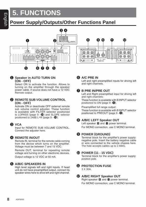
Speaker in AUTO TURN ON (ON - OFF)
Select ON to activate the function. Allows to turning on the amplifier through the speaker power cable, if source does not have a 12 VDC Remote output.
REMOTE SUB VOLUME CONTROL (ON - OFF)
Activate ON or deactivate OFF external remote sub volume control adjuster. These function is available with FILTER selector positioned to LOPASS (page 9 - ) and SLOPE selector positioned to 24dB L+R (page 9 - ).
REMOTE IN/OUT Remote IN, terminal for the remote cable coming
from the device which turns on the amplifier. Voltage must be between 7 and 15 VDC.
Remote OUT, terminal for repeating remote voltage and turning on other electronic devices.
Output voltage is 12 VDC at 50 mA.
A/C PRE IN Left and right preamplified inputs for driving left
and right channels.
1
2
4
A/B/C SPEAKERS IN High level signals left and right inputs. If head
unit do not have preamplified output, connect its speaker wires here to drive left and right channel.
5
6
A/B/C LEFT Speaker OUT Left speaker and power terminal. For MONO connection, use C MONO terminal.
8
POWER (11 - 15 VDC) Terminal block for the amplifier's power supply:
position pole.
PROTECTION FUSE 3 X 30A.
A/B/C RIGHT Speaker OUT Right speaker and power terminal. For MONO connection, use C MONO terminal.
10
11
151514
12
VCA Input for REMOTE SUB VOLUME CONTROL.
Connect the adjuster here.
3
7 B PRE IN/PRE OUT Left and Right preamplified input for driving left
and right channels: These function is available with B INPUT selector
positioned to ON (page 9 - ). Preamplified full range output: These function is available with B INPUT selector
positioned to PREOUT (page 9 - ).
POWER (GROUND) Terminal block for the amplifier's power supply:
negative pole. Insert the battery negative cable or wire connected to the vehicle chassis here. The hole accepts cables up to 2 AWG.
9
9
9
9ADP6000
EnglishControl Panel
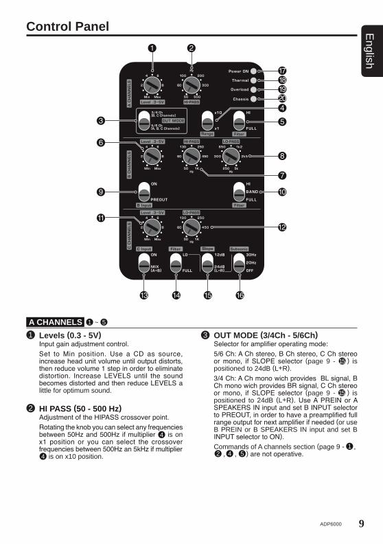
Levels (0.3 - 5V) Input gain adjustment control. Set to Min position. Use a CD as source,
increase head unit volume until output distorts, then reduce volume 1 step in order to eliminate distortion. Increase LEVELS until the sound becomes distorted and then reduce LEVELS a little for optimum sound.
1
HI PASS (50 - 500 Hz) Adjustment of the HIPASS crossover point. Rotating the knob you can select any frequencies
between 50Hz and 500Hz if multiplier is on x1 position or you can select the crossover frequencies between 500Hz an 5kHz if multiplier is on x10 position.
2
4
OUT MODE (3/4Ch - 5/6Ch) Selector for amplifier operating mode: 5/6 Ch: A Ch stereo, B Ch stereo, C Ch stereo
or mono, if SLOPE selector (page 9 - ) is positioned to 24dB (L+R).
3/4 Ch: A Ch mono wich provides BL signal, B Ch mono wich provides BR signal, C Ch stereo or mono, if SLOPE selector (page 9 - ) is positioned to 24dB (L+R). Use A PREIN or A SPEAKERS IN input and set B INPUT selector to PREOUT, in order to have a preamplified full range output for next amplifier if needed (or use B PREIN or B SPEAKERS IN input and set B INPUT selector to ON).
Commands of A channels section (page 9 - , , , ) are not operative.
3
4
A CHANNELS 1 ~ 5
15
15
142 5

10 ADP6000
English
Control Panel
Levels (0.3 - 5V) Input gain adjustment control. Set to Min position. Use a CD as source,
increase head unit volume until output distorts, then reduce volume 1 step in order to eliminate distortion. Increase LEVELS until the sound becomes distorted and then reduce LEVELS a little for optimum sound.
11
Levels (0.3 - 5V) Input gain adjustment control. Set to Min position. Use a CD as source,
increase head unit volume until output distorts, then reduce volume 1 step in order to eliminate distortion. Increase LEVELS until the sound becomes distorted and then reduce LEVELS a little for optimum sound.
6
HI PASS (50 Hz - 1 kHz) Adjustment of the HIPASS crossover point. Rotating the knob you can select any frequencies
between 50Hz and 1kHz.
7
LO PASS (250 Hz - 1 kHz) Adjustment of the LOPASS crossover point. Rotating the knob you can select any frequencies
between 250Hz and 5kHz.
8
B Input (PREOUT - ON) Select PRE OUT in order to activate a
preamplified full range output (page 8 - ). Inputs A PREIN or A SPEAKERS IN drives A
CHANNELS and B CHANNELS. Select ON to drive B CHANNELS by B PREIN
or B SPEAKERS IN inputs.
9
7
Filter (FULL - BAND - HI) Select FULL to drive full range power outputs.
The full frequencies bandwith will be output to power output connectors.
Select BAND to drive a MIDRANGE. Use HI PASS and LO PASS to adjust BAND PASS action
Select HI to drive a MIDRANGE or a TWEETER. Adjuster LO PASS is not operative.
In HI or BAND mode, the frequencies below and above crossover point will be attenuated at 12dB/octave.
10
LO PASS (50 Hz - 1 kHz) Adjustment of the LOPASS crossover point. Rotating the knob you can select any frequencies
between 50Hz and 1kHz.
12
Filter (FULL - LO) Select LO or FULL filter function. If full is selected,
the full frequencies bandwith will be output to power output connection at C CHANNELS output.
14
C Input (MIX(A+B) - ON) Select MIX(A+B) in order to drive C CHANNELS
by a sum of A and B INPUT signals. If B INPUT selector is positioned to PRE OUT, C
CHANNELS is driven by A INPUT signals only. Inputs A PRE IN or A SPEAKERS IN drives A
CHANNELS and B CHANNELS. Select ON to drive C CHANNELS by C PRE IN
or C SPEAKERS IN inputs.
13
B CHANNELS 6 ~ 10
C CHANNELS 11 ~ 16
Filter (FULL - HI) Select FULL to drive full range power outputs.
The full frequencies bandwith will be output to power output connectors.
Select HI to drive a MIDRANGE/TWEETER. In Hi mode, the frequencies below crossover
point will be attenuated with a 12dB/octave slope.
5 Range (x1-x10) Multiplier for HIPASS filter. Selecting x1 you have
normal xover frequencies (50Hz - 500Hz). Selecting x10 the frequencies will be multiply by
10 (500Hz - 5kHz).
4
11ADP6000
English
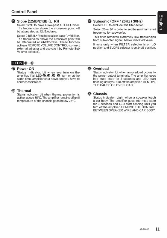
Slope (12dB/24dB (L+R)) Select 12dB to have a low-pass STEREO filter.
The frequencies above the crossover point will be attenuated at 12dB/octave.
Select 24dB (L+R) to have a low-pass (L+R) filter. The frequencies above the crossover point will be attenuated at 24dB/octave. These function activate REMOTE VOLUME CONTROL (connect external adjuster and activate it by Remote Sub Volume selector).
15 Subsonic (OFF / 20Hz / 30Hz) Select OFF to exclude this filter action. Select 20 or 30 in order to set the minimum start
frequency for subwoofer. This filter removes extremely low frequencies
from subwoofer signal, below indicated value. It acts only when FILTER selector is on LO
position and SLOPE selector is on 24dB position.
16
Chassis Status indicator. Light when a speaker touch
a car body. The amplifier goes into mute state for 3 seconds and LED start flashing until you turn off the amplifier. REMOVE THE CONTACT BETWEEN SPEAKER WIRE AND CAR BODY.
20
Overload Status indicator. Lit when an overload occurs to
the power output terminals. The amplifier goes into mute state for 3 seconds and LED start flashing until you turn off the amplifier. REMOVE THE CAUSE OF OVERLOAD.
19
Thermal Status indicator. Lit when thermal protection is
active, above 85°C. The amplifier remains off until temperature of the chassis goes below 75°C.
18
Power ON Status indicator. Lit when you turn on the
amplifier. If all LED , , , , turn on at the same time, amplifier shut down and you have to contact assistance.
17
17
18 19 20
Control Panel
LEDS 17 ~ 20
12 ADP6000
English
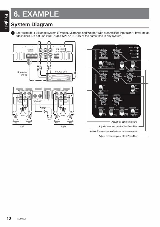
6. EXAMPLESystem Diagram Stereo mode- Full range system (Tweeter, Midrange and Woofer) with preamplified inputs or Hi-level inputs
(dash line)- Do not use PRE IN and SPEAKERS IN at the same time in any system.1
Source unitSpeakers wiring
Adjust for optimum sound
Adjust crossover point of Lo-Pass filter Left Right
ch A
ch B ch B
ch A
Batt
ch Cch C
Adjust frequencies multiplier of crossover point
Adjust crossover point of Hi-Pass filter
WF WF
MID MID
TW TW

13ADP6000
English
Stereo mode- 4 Channels.2
Source unit
WF
4 Channels Stereo mode and 1 Mono Mode (Bridge) for Source unit without SubWoofer output.
System Diagram
3
Adjust for optimum sound
N.A.
Adjust crossover frequencies of Lo-Pass filter
ch Cch B
Left RightWF
Batt
ch C ch B
Source unit
SUB
ch A
ch B ch B
ch A
Batt
Left Right
Adjust for optimum sound
N.A.
Adjust crossover frequencies of Lo-Pass filter
14 ADP6000
English
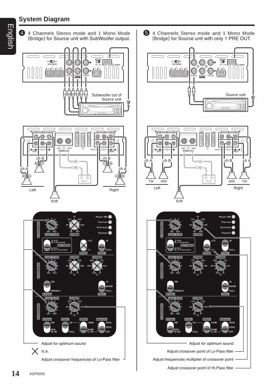
4 Channels Stereo mode and 1 Mono Mode (Bridge) for Source unit with SubWoofer output.
4
Subwoofer out of Source unit
ch A ch A
Batt
SUB
System Diagram
ch B ch B
Adjust for optimum sound
N.A.
Adjust crossover frequencies of Lo-Pass filter
Left Right
4 Channels Stereo mode and 1 Mono Mode (Bridge) for Source unit with only 1 PRE OUT.
5
Source unit
ch A ch B ch B ch A
Batt
RightLeft
SUB
TW MID MID TW
Adjust for optimum sound
Adjust crossover point of Lo-Pass filter
Adjust frequencies multiplier of crossover point
Adjust crossover point of Hi-Pass filter

15ADP6000
English
7. BLOCK DIAGRAM
Non
Inde
pend
ent
Freq
uenc
yC
ontro
l
Inde
pend
ent
Freq
uenc
yC
ontro
lH
I-PAS
SLO
-PAS
SBA
ND
PASS
Non
Inve
rted
Ampl
ifier
Inve
rted
Ampl
ifier
Ster
eo S
igna
l
A C
hann
els
MO
NO
IN A
Lef
tFi
lter B
Lef
tO
UT
Left
12dB
24dB
( L+ R
)
FULL
LO
50-1
k
5/6
Ch
( A,B
,C C
hann
els)
mix
L+R
24dB
/Oct
.
MIX
A PR
E IN
C P
RE
IN
B P
RE
IN/
PRE
OU
T
MIX
( A+ B
)
ON
ext.p
ot
OFF
20H
z
30H
z
B C
hann
els
MO
NO
IN A
Rig
htFi
lter B
Rig
htO
UT
Rig
ht
C C
hann
els
MO
NO
IN A
or C
( MIX
)Fi
lter C
OU
T M
ono
L+R
12dB
24dB
0.3-
5
ON
ON
PREO
UT
PREO
UT
0.3-
550
-1k
250-
2.5k
FULL
BA
ND
HI
3/4
Ch
( B,C
Cha
nnel
s)
5/6
Ch
( A,B
,C C
hann
els)
3/4
Ch
( B,C
Cha
nnel
s)
FULL
HI
50-5
000.
3-5

16 ADP6000
English
For maximum performance, always use new, good quality cables: their outer jacket must not be spoiled and the copper must not show oxidation. For proper operation, always consider the length of the connection, the load and the current it has to handle. Clarion products are the most flexible and complete: they are designed and built in order to get the best out of every installation, especially when used with Clarion amplifiers.
How to calculate your system current consumption
TPx2VbattI =
12650 x 2
Appl
ied
Pow
er
Cab
le D
iam
eter
Connection Length
Power & Ground cable calculation tableMinimum gauge size recommended for MAINPOWER & POWER FLOW cables. MAINPOWER cables ensure higher istantaneous current transfer.
Cable Size
Cur
rent
Dra
w I
( A)
Cable Length (m)
8. CABLESConnection Cables
Speaker CableThe table refers to continuous power into 4 Ohm load. If load decreases, cable size will have to in-crease proportionally.
Power supply cableIf you don’t know your system current consumption, find it using the mathematical formula below and find this same value on the left hand column of the table. Then calculate the length of your connection and find this same value on the bottom column of the table. At the point where these two values cross is the minimum sec-tion in gauge (AWG) recommended for building a high performance, reliable system.
I = Current consumption of your system in ampere (A);
TP = Total power (RMS) of channels of all amplifiers in your system;
Vbatt = Usual ly va lue is 12 V, the nominal automotive electrical system voltage.
Examples: Your total system power (RMS) of all channels in all
amplifiers is a combined 650 W. Your amplifier average 50% efficiency, as most ampli-
fiers today. Your electrical system is 12 Volt. I = = 108,3 A Current consumption

17ADP6000
EnglishLayout
GroundTerminals: minimizing resistance and the consequent power losses associated with poor system grounding.
1
BatteryClamps: ensure high current transfer without the power robbing consequences of a high resistance connection.
FuseHolders: are the first line of protection for your vehicle and yourself from dangerous short circuits. The high temperature case and waterproof construction ensure reliability in any environmental condition.
Power&GroundCables: are of fundamental importance to obtain reference performance in your car audio/video system. The special structure of Main Power and Power Flow cables minimize eddy current power losses and allow high instantaneous current transfer, enabling you to experience the full dynamics of your music.
FuseDistribution: their name tells you their function: transferring energy to electronic devices. They are available in various models, even modular and they can house the protection fuse. Fuse distributions are to be used in every system where you need to transfer a huge amount of current without losses.
GroundDistributionBlocks: are as important as the power distribution to your systems overall performance. Solid, low resistance ground points prevent harmful voltage differences between components and improve high-level current transfer without power loss.
SUPERFARAD™: capacitors act as a “current reserve” storing DC energy for when your amplifiers demand it the most.
SpeakerCables: provide that last step in the faithful reproduction of your music. They ensure the transfer of music to your speakers without the coloration or degradation of the signal.
AudioInterconnects: are the first component in your system that audio signals pass through. For faithful reproduction, they must transfer these signals from the head-unit to the amplifiers without modifying the sound, while at the same time, reject the tremendous amount of noise radiated by on-board computer-controlled devices in your automobile.
2
3
4
5
6
7
8
9

18 ADP6000
English Power supplyVoltage 11 ~ 15 VDC Minimum idling current 1.9 AIdling current when off 0.02 mAConsumption @ 14.4 VDC (MAX musical power) 65 ARemote IN Voltage 7 ~ 15 VDC (1.3 mA)Remote OUT Voltage 12 VDC (50 mA)Internal fuse 3 x 30 A
AmplifierstageDistortion - THD (1 kHz @ 4 Ω) 0.05%Frequency Response (-3 dB) 4 Hz ~ 100 kHzS/N ratio (A-weighted @ 1 VRMS) >105 dBDamping factor (1 kHz @ 4 Ω) >120Input sensitivity (PRE IN) 0.3 ~ 5 VInput sensitivity (Speaker IN) 1.4 ~ 24 VInput impedance (PRE IN) 15 kΩInput impedance (Speaker IN) 5 kΩLoad impedance (MIN) 6 Channels 4 x 2 Ω + 2 x 1 Ω 5 Channels 5 x 2 Ω 4 Channels 2 x 4 Ω + 2 x 1 Ω 3 Channels 2 x 4 Ω + 1 x 2 ΩNominal output power (RMS)PN @ 12 VDC 0.3% THD 65 W x 4 + 70 W x 2Output power (RMS) @ 14.4 VDC 1% THD 6 Channels 6 Ch x 4 Ω 70 W x 4 + 75 W x 2 6 Channels 6 Ch x 2 Ω 115 W x 4 + 130 W x 2 6 Channels 4 Ch x 2 Ω + 2 Ch x 1 Ω 100 W x 4 + 200 W x 2 5 Channels 4 Ch x 4 Ω + 1 Ch x 4 Ω - 5 Channels 4 Ch x 4 Ω + 1 Ch x 2 Ω - 5 Channels 4 Ch x 2 Ω + 1 Ch x 2 Ω - 4 Channels 2 Ch x 4 Ω + 2 Ch x 2 Ω - 4 Channels 2 Ch x 4 Ω + 2 Ch x 1 Ω - 3 Channels 2 Ch x 4 Ω + 1 Ch x 4 Ω - 3 Channels 2 Ch x 4 Ω + 1 Ch x 2 Ω -
9. TECHNICAL SPECIFICATIONS
19ADP6000
English
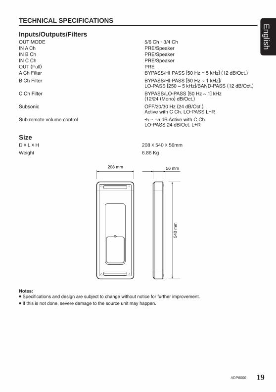
SizeD x L x H 208 x 540 x 56mm Weight 6.86 Kg
Notes: Specifications and design are subject to change without notice for further improvement. If this is not done, severe damage to the source unit may happen.
TECHNICAL SPECIFICATIONS
Inputs/Outputs/FiltersOUT MODE 5/6 Ch - 3/4 ChIN A Ch PRE/SpeakerIN B Ch PRE/SpeakerIN C Ch PRE/SpeakerOUT (Full) PREA Ch Filter BYPASS/HI-PASS [50 Hz ~ 5 kHz] (12 dB/Oct.)B Ch Filter BYPASS/HI-PASS [50 Hz ~ 1 kHz]/ LO-PASS [250 ~ 5 kHz]/BAND-PASS (12 dB/Oct.)C Ch Filter BYPASS/LO-PASS [50 Hz ~ 1] kHz (12/24 (Mono) dB/Oct.) Subsonic OFF/20/30 Hz (24 dB/Oct.) Active with C Ch. LO-PASS L+R Sub remote volume control -5 ~ +5 dB Active with C Ch. LO-PASS 24 dB/Oct. L+R

Clarion MalaysiaAll Rights Reserved. Copyright © 2012: Clarion Co., Ltd.
Printed in Malaysia EE-1465B-A 280-8987-01