overview - platt electric supply · smart power (soft start, power monitor) ... (4.33 to 436...
TRANSCRIPT
Publication 1394-5.0 — May 2000
Chapter 1
Overview
The 1394 System The 1394 is a modular, multi-axis motion control and drive system
family. Its unique design allows the 1394 to be used as an integrated
motion controller and drive system (GMC) with Turbo or standard
IMC S Class Compact functionality, an integrated 9/440 CNC
system, a 9/Series CNC digital interface drive system, a SERCOS
servo drive system, or an analog servo drive system.
All 1394 systems provide direct line connection (transformerless) for
360 and 480V three-phase input power, efficient IGBT power
conversion, and slide-and-lock, module-to-module connection
systems. Each system module can be configured with up to four axis
modules, with each axis module interfacing to a motor. The 1394
provides significant panel space and interconnect savings.
Series Note
Series C system modules (catalog numbers 1394C-SJTxx-x) and axis
modules (catalog numbers 1394C-AMxx and -AMxx-IH) include
features not available on Series A and B modules (catalog numbers
1394-SJTxx-x and 1394-AMxx).
Series C system modules are interchangeable with Series A and B.
Likewise, Series A, B, and C axis modules are interchangeable with
each other.
Series C is recommended for all new applications. See the tables
above for feature availability. For help in determining the series of
your module(s), refer to the section Module Series Designator in the
Preface.
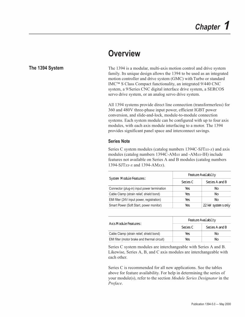
System Module Features: Feature AvailabilitySeries C Series A and B
Connector (plug-in) input power termination Yes NoCable Clamp (strain relief, shield bond) Yes NoEMI filter (24V input power, registration) Yes NoSmart Power (Soft Start, power monitor) Yes 22 kW systems only
Axis Module Features: Feature AvailabilitySeries C Series A and B
Cable Clamp (strain relief, shield bond) Yes NoEMI filter (motor brake and thermal circuit) Yes No
Publication 1394-5.0 — May 2000
Overview 1-3
1394 System Overview GMC System
The 1394 GMC System provides all the functionality of the IMC S
Class Compact Motion Controller and power conversion within the
1394 system module. Allen-Bradley offers two versions of the 1394
GMC system module (Standard GMC and GMC Turbo). Both
systems are completely programmed and commissioned using
GML (Graphical Motion Control Language), offer Allen-Bradley
DH485, RS-232, and RS-422 as standard communications, and have
Remote I/O and AxisLink available as communication options.
The 1394x-SJTxx-C (Standard GMC) system supports four axis
modules and provides four channels of auxiliary encoder input. The
1394C-SJTxx-L (Standard GMC) provides the same functionality of
the 1394x-SJTxx-C, but supports only one axis module and provides
two channels of auxiliary encoder input.
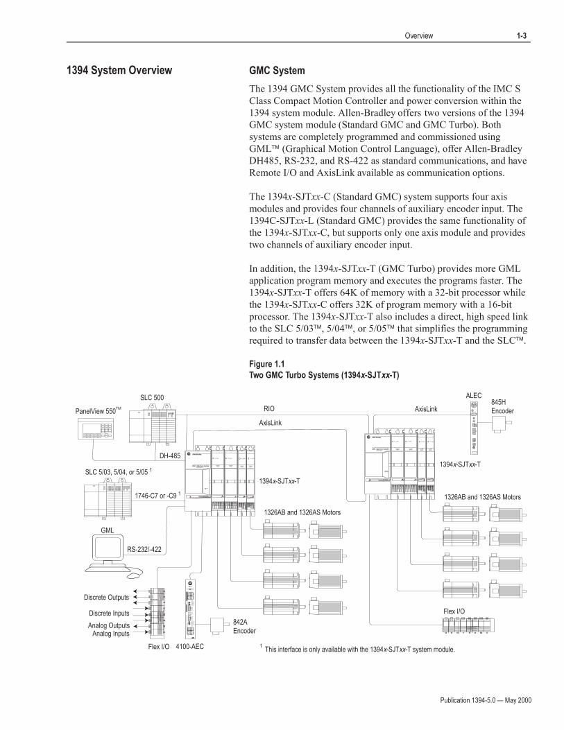
In addition, the 1394x-SJTxx-T (GMC Turbo) provides more GML
application program memory and executes the programs faster. The
1394x-SJTxx-T offers 64K of memory with a 32-bit processor while
the 1394x-SJTxx-C offers 32K of program memory with a 16-bit
processor. The 1394x-SJTxx-T also includes a direct, high speed link
to the SLC 5/03, 5/04, or 5/05 that simplifies the programming
required to transfer data between the 1394x-SJTxx-T and the SLC.
Figure 1.1
Two GMC Turbo Systems (1394x-SJTxx-T)
RIO
DH-485
AxisLink
GML
1326AB and 1326AS Motors
1326AB and 1326AS Motors
Flex I/O
ALEC845HEncoder
RS-232/-422
SLC 500
SLC 5/03, 5/04, or 5/05 1
1394x-SJTxx-T
1394x-SJTxx-T
PanelView 550
This interface is only available with the 1394x-SJTxx-T system module.1
TM
1746-C7 or -C9 1
Flex I/O
Discrete Outputs
Discrete Inputs
Analog OutputsAnalog Inputs
AEC
Reset
Axis 0 Axis 1
A
B
A
B
Axis
1A
xis
0
2
1
SS
IC
on
tro
l
Co
nfig
ura
tio
nC
on
fig
ura
tio
n
Sw
itch
es
Sw
itch
es
En
co
de
rE
nco
de
rP
ow
er
SS
IC
on
tro
l
A B
109876
2
543
1
876 2
43
15
A B
109876
2
543
1
876 2
43
15
4100-AEC
842AEncoder
AxisLink
DANGERRISK OF ELECTRICAL SHOCK. HIGH VOLTAGE MAYEXIST UP TO FIVE MINUTES AFTER REMOVING POWER.
DANGERRISK OF ELECTRICAL SHOCK. HIGH VOLTAGE MAYEXIST UP TO FIVE MINUTES AFTER REMOVING POWER.
Publication 1394-5.0 — May 2000
Overview 1-9
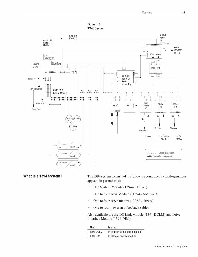
Figure 1.6
9/440 System
What is a 1394 System? The 1394 system consists of the following components (catalog number
appears in parenthesis):
• One System Module (1394x-SJTxx-x)
• One to four Axis Modules (1394x-AMxx-xx)
• One to four servo motors (1326Ax-Bxxxx)
• One to four power and feedback cables
Also available are the DC Link Module (1394-DCLM) and Drive
Interface Module (1394-DIM).
Terminal type connection
Optical signal cable
The: Is used:
1394-DCLM In addition to the axis module(s)
1394-DIM In place of an axis module.
Publication 1394-5.0 — May 2000
1-10 Overview
Axis modules are connected to system modules using slide-and-lock,
module-to-module connections. For information on motors and cables,
refer to the 1326AB 460V, Torque Plus Series, AC Servo Motors Product
Data (publication 1326A-2.9), 1326AS Series 460V, Low Inertia,
Brushless Servo Motors Product Data (publication 1326A-2.10), and
1326 Cables for 460V AC Servo Motors Product Data (publication
1326A-2.11).
In addition to the equipment shown above, you will need to supply the
following:
• Three phase input contactor
• Three phase input fusing
• 24V AC or DC logic power for system module and contactor
enable (Analog Servo only)/DRIVEOK power (all modules)
Refer to Appendix A for information on these topics.
Note: An external shunt resistor kit (1394-SR10A) is available for 5 and 10 kW systems with regenerative loads that exceed the capacity of the internal 200W shunt resistor provided. Most 5 and 10 kW systems will not require a shunt resistor kit. All 22 kW 1394 based products require an external shunt module (1394-SR9Ax or 1394-SR36Ax). This includes both 1394 and 8520 catalog items.
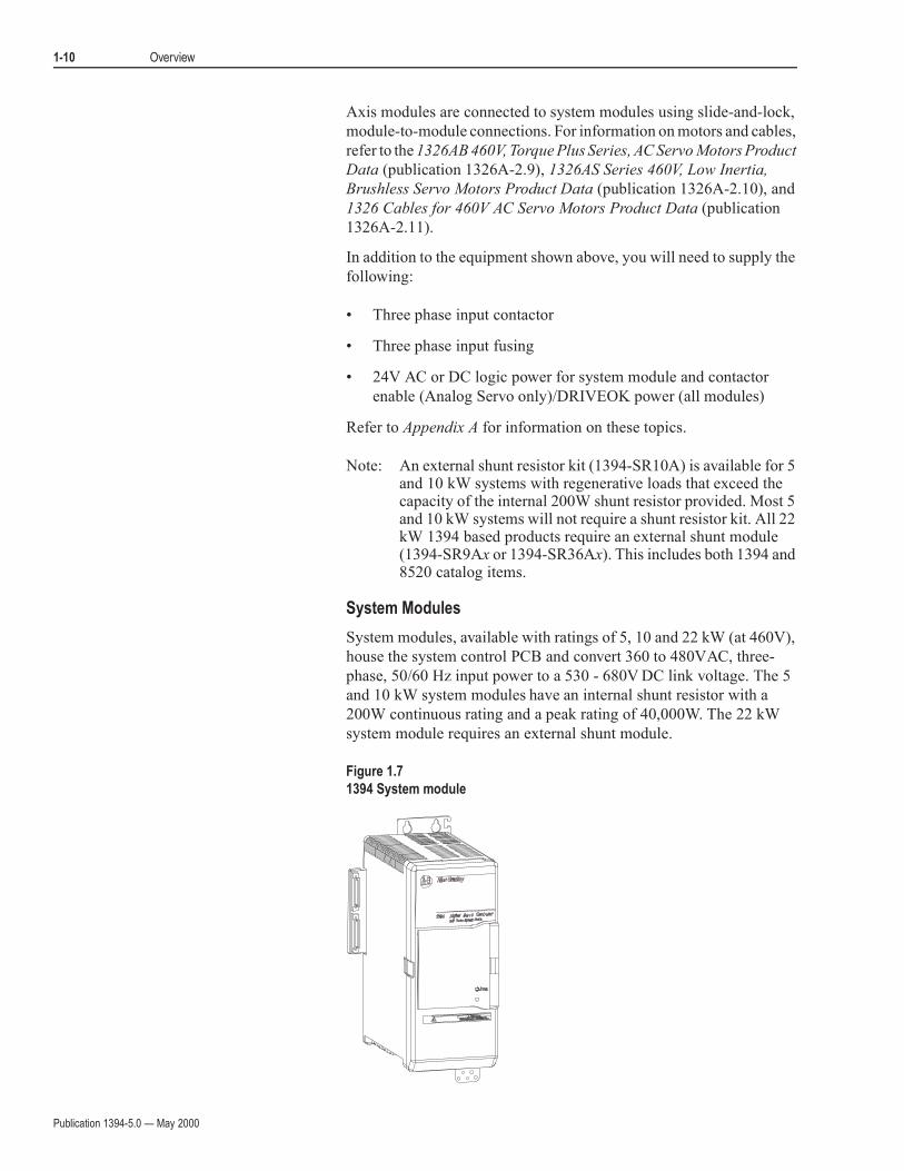
System Modules
System modules, available with ratings of 5, 10 and 22 kW (at 460V),
house the system control PCB and convert 360 to 480VAC, three-
phase, 50/60 Hz input power to a 530 - 680V DC link voltage. The 5
and 10 kW system modules have an internal shunt resistor with a
200W continuous rating and a peak rating of 40,000W. The 22 kW
system module requires an external shunt module.
Figure 1.7
1394 System module
DANGER
RISK OF ELECTRICAL SHOCK. HIGH VOLTAGE MAYEXIST UP TO FIVE MINUTES AFTER REMOVING POWER.
Publication 1394-5.0 — May 2000
Overview 1-11
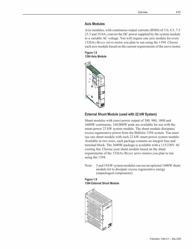
Axis Modules
Axis modules, with continuous output currents (RMS) of 3.0, 4.5, 7.5
23.3 and 35.0A, convert the DC power supplied by the system module
to a variable AC voltage. You will require one axis module for every
1326Ax-Bxxxx servo motor you plan to run using the 1394. Choose
each axis module based on the current requirements of the servo motor.
Figure 1.8
1394 Axis Module
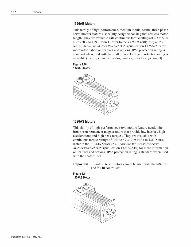
External Shunt Module (used with 22 kW System)
Shunt modules with (rms) power output of 300, 900, 1800 and
3600W continuous, 160,000W peak are available for use with the
smart power 22 kW system module. The shunt module dissipates
excess regenerative power from the Bulletin 1394 system. You must
use one shunt module with each 22 kW smart power system module.
Available in two sizes, each package contains an integral fuse and
terminal block. The 3600W package is available with a 115/230V AC
cooling fan. Choose your shunt module based on the shunt
requirements of the 1326Ax-Bxxxx servo motors you plan to run
using the 1394.
Note: 5 and 10 kW system modules can use an optional 1400W shunt module kit to dissipate excess regenerative energy (unpackaged components).
Figure 1.9
1394 External Shunt Module
Publication 1394-5.0 — May 2000
1-12 Overview
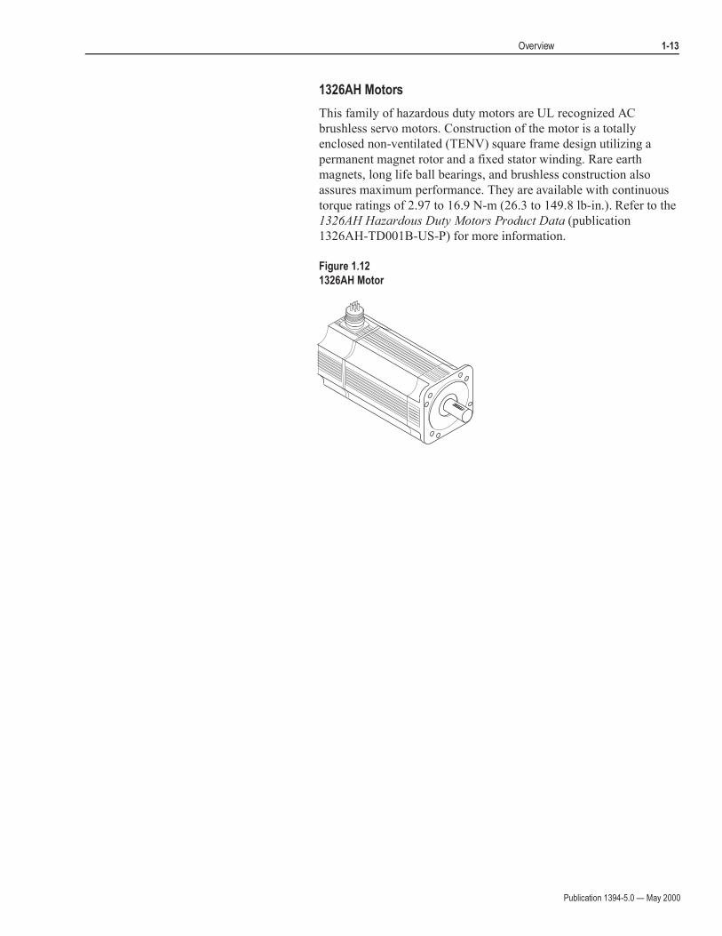
1326AB Motors
This family of high-performance, medium inertia, ferrite, three-phase
servo motors feature a specially designed housing that reduces motor
length. They are available with continuous torque ratings of 2.3 to 53.0
N-m (20.7 to 469.0 lb-in.). Refer to the 1326AB 460V, Torque Plus
Series, AC Servo Motors Product Data (publication 1326A-2.9) for
more information on features and options. IP65 protection rating is
standard when used with the shaft oil seal kit. IP67 protection rating is
available (specify -L in the catalog number, refer to Appendix D).
Figure 1.10
1326AB Motor
1326AS Motors
This family of high-performance servo motors feature neodymium-
iron-boron permanent magnet rotors that provide low inertias, high
accelerations and high peak torques. They are available with
continuous torque ratings of 0.49 to 49.3 N-m (4.33 to 436 lb-in.).
Refer to the 1326AS Series 460V, Low Inertia, Brushless Servo
Motors Product Data (publication 1326A-2.10) for more information
on features and options. IP65 protection rating is standard when used
with the shaft oil seal.
Important: 1326AS-Bxxxx motors cannot be used with the 9/Series and 9/440 controllers.
Figure 1.11
1326AS Motor
Publication 1394-5.0 — May 2000
Overview 1-13
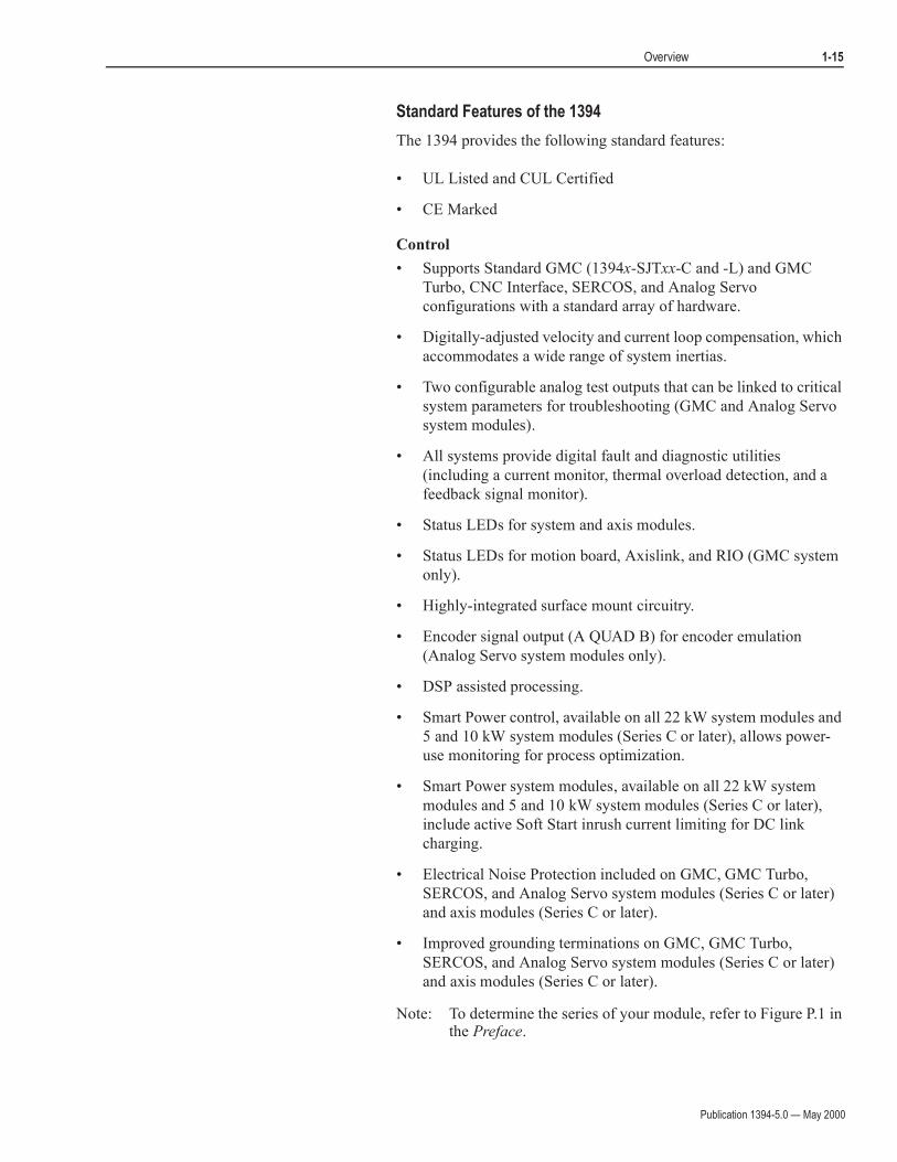
1326AH Motors
This family of hazardous duty motors are UL recognized AC
brushless servo motors. Construction of the motor is a totally
enclosed non-ventilated (TENV) square frame design utilizing a
permanent magnet rotor and a fixed stator winding. Rare earth
magnets, long life ball bearings, and brushless construction also
assures maximum performance. They are available with continuous
torque ratings of 2.97 to 16.9 N-m (26.3 to 149.8 lb-in.). Refer to the
1326AH Hazardous Duty Motors Product Data (publication
1326AH-TD001B-US-P) for more information.
Figure 1.12
1326AH Motor

Publication 1394-5.0 — May 2000
1-14 Overview
Drive Interface Module
The 1394-DIM (Drive Interface Module) provides four channels of
analog output, four drive enable outputs, and four drive fault inputs.
The 1394-DIM allows the 1394x-SJTxx-C, -T, or -L system module to
be used to control any external drive with a ±10V velocity torque
reference command and quadrature encoder output. Each 1394-DIM
can support up to four drives. However, the maximum number of axes
(1394-DIM controlled drives plus 1394x-AMxx axis modules) cannot
exceed four per 1394x-SJTxx-C or -T system module and one per
1394C-SJTxx-L system module. The 1394-DIM is not compatible
with the 1394x-SJTxx-A system module.
Figure 1.13
Drive Interface Module
DC Link Module
The 1394-DCLM (DC Link Module) provides additional load
leveling and energy storage (capacitance) for 1394 systems. This
allows additional regenerative energy to be stored during the machine
cycle, increasing system capacity, lowering cycle time, and avoiding
resistive heat loss. The module can be used alone or two modules can
be used to interconnect two 1394 systems using the DC Link cable.
Figure 1.14
DC Link Module
Publication 1394-5.0 — May 2000
Overview 1-15
Standard Features of the 1394
The 1394 provides the following standard features:
• UL Listed and CUL Certified
• CE Marked
Control
• Supports Standard GMC (1394x-SJTxx-C and -L) and GMC
Turbo, CNC Interface, SERCOS, and Analog Servo
configurations with a standard array of hardware.
• Digitally-adjusted velocity and current loop compensation, which
accommodates a wide range of system inertias.
• Two configurable analog test outputs that can be linked to critical
system parameters for troubleshooting (GMC and Analog Servo
system modules).
• All systems provide digital fault and diagnostic utilities
(including a current monitor, thermal overload detection, and a
feedback signal monitor).
• Status LEDs for system and axis modules.
• Status LEDs for motion board, Axislink, and RIO (GMC system
only).
• Highly-integrated surface mount circuitry.
• Encoder signal output (A QUAD B) for encoder emulation
(Analog Servo system modules only).
• DSP assisted processing.
• Smart Power control, available on all 22 kW system modules and
5 and 10 kW system modules (Series C or later), allows power-
use monitoring for process optimization.
• Smart Power system modules, available on all 22 kW system
modules and 5 and 10 kW system modules (Series C or later),
include active Soft Start inrush current limiting for DC link
charging.
• Electrical Noise Protection included on GMC, GMC Turbo,
SERCOS, and Analog Servo system modules (Series C or later)
and axis modules (Series C or later).
• Improved grounding terminations on GMC, GMC Turbo,
SERCOS, and Analog Servo system modules (Series C or later)
and axis modules (Series C or later).
Note: To determine the series of your module, refer to Figure P.1 in the Preface.
Publication 1394-5.0 — May 2000
1-16 Overview
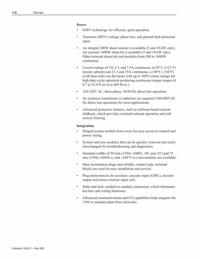
Power
• IGBT technology for efficient, quiet operation.
• Transient (MOV) voltage, phase loss, and ground fault protected
input.
• An integral 200W shunt resistor is available (5 and 10 kW only).
An external 1400W shunt kit is available (5 and 10 kW only).
Other external shunt kits and modules from 300 to 3600W
continuous.
• Current ratings of 3.0, 4.5, and 7.5A continuous, at 50° C (122° F)
(inside cabinet) and 23.3 and 35A continuous, a t 40°C ( 104°F)
(with heat sinks out the back) with up to 300% motor ratings for
high duty-cycle operation producing continuous torque ranges of
0.7 to 53.0 N-m (6 to 469 lb-in.).
• 324-528V AC, three-phase, 50/60 Hz direct line operation.
• No isolation transformer or inductors are required (360/480VAC
Hz direct line operation) for most applications.
• Advanced protective features, such as software-based current
foldback, which provides overload tolerant operation and soft
current limiting.
Integration
• Hinged system module front cover for easy access to control and
power wiring.
• System and axis modules that can be quickly removed and easily
interchanged for troubleshooting and diagnostics.
• Standard widths of 50 mm (1394x-AM03, -04, and -07) and 75
mm (1394x-AM50-xx and -AM75-xx) axis modules are available.
• Mass termination plugs and reliable, contact-type, terminal
blocks are used for easy installation and service.
• Plug interconnects for auxiliary, encoder input (GMC), encoder
output and motor resolver input (all).
• Slide-and-lock, module-to-module connection, which eliminates
bus bars and wiring harnesses.
• Advanced communications and I/O capabilities help integrate the
1394 to standard plant floor networks.
Publication 1394-5.0 — May 2000
Appendix A
Specifications
Chapter Objectives Appendix A contains specifications and dimensions for the 1394 system
and dimensions and operating characteristics for the 1326AB/AS series
servo motors. This appendix covers:
• System specifications
• Environmental specifications
• Power dissipation
• Communication specifications
• Dimensions
• Servo motor performance data
System Specifications General 1394 specifications are provided below. Specifications are for
reference only and are subject to change without notice.
Certification
The 1394 is certified for the following when the product or package is
marked:
• UL listed (File E59272)
• CUL listed
• CE marked for all applicable directives

Publication 1394-5.0 — May 2000
A-2 Specifications
System Modules
The table below lists the specifications for system modules.
The: For the 1394x-SJT05 1,2 is: For the 1394x-SJT10 1,2 is: For the 1394x-SJT22 1 is:
Rated AC input voltage 324-528V AC, 50/60 Hz
Three phase
324-528V AC, 50/60 Hz
Three phase
324-528V AC, 50/60 Hz
Three phase
AC input current 6.5A 13.0A 28.6A
Peak inrush current4,5
(Series A and B)3975A 1300A 697A < 1µs
Peak inrush current4
(Series C)
697A < 1µs 697A < 1µs 697A < 1µs
Line loss ride through 20 ms 20 ms 20 ms
Nominal bus output voltage 530/680V DC 530/680V DC 530/680V DC
Continuous power output 4/5 kW 8/10 kW 17/22 kW
Peak power output 28 kW 28 kW 136 kW
Efficiency 99% 99% 98%
Number of Electronic Cam
Profile Points
13,000 Master/slave 13,000 Master/slave 13,000 Master/slave
Weight (Series A and B) 11 kg (24.25 lb) 11 kg (24.25 lb) 12.7 kg (28.0 lb)
Weight (Series C) 10.68 kg (23.5 lb) 10.68 kg (23.5 lb) 12.9 kg (28.5 lb)
Continuous current output 7.36A 14.73A 33.8A
Peak current output 15.0A 29.46A 200A
Capacitance
(Series A and B)
220 µF 330 µF 660 µF
Capacitance
(Series C)
220 µF 345 µF 660 µF
Inductance 1000 µH 750 µH 500 µH
Internal shunt resistor 200W continuous, 40,000W peak (two second maximum on
time)
No internal Shunt Resistor
1 The Standard GMC and GMC Turbo system modules are identical except that the GMC Turbo (1394x-SJTxx-T) offers a SLC backplane
interface and 64K of memory with a 32-bit processor while the Standard GMC (1394x-SJTxx-C) offers 32K of program memory with a 16-
bit processor without the SLC interface.2 The Standard GMC (1394C-SJTxx-L) is functionally the same as the (1394x-SJTxx-C) except it supports one axis and provides two auxiliary
encoder inputs.3 To determine the series of your module, refer to Figure P.1 in the Preface.4 5 and 10 kW (Series C) system modules and all 22 kW system modules are limited to four contactor cycles per minute. 5 and 10 kW (Series
A and B) system modules are limited to an average of four contactor cycles per hour.
Peak inrush current for5 and 10 kW systems(Series A and B)
5
= ( line voltage x 1.1 x 2 )
Lsystem( )(Csystem + Caxes)
Where: L = Inductance
C = Capacitance

Publication 1394-5.0 — May 2000
Specifications A-3
Axis Modules
The table below lists the specifications for the axis modules.
Contact Ratings
The table below lists the contact ratings of the drive relay outputs.
The: For the 1394x-AM03 is: For the 1394x-AM04 is: For the 1394x-AM07 is:For the 1394x-AM50
and 1394C-AM50-IH is:
For the 1394x-AM75
and 1394C-AM75-IH is:
Speed Regulation1 0 to 0.05% of base
speed with 100% torque
disturbance
0 to 0.05% of base
speed with 100% torque
disturbance
0 to 0.05% of base
speed with 100% torque
disturbance
0 to 0.05% of base speed
with 100% torque
disturbance
0 to 0.05% of base speed
with 100% torque
disturbance
Static Gain
(rms A/mV)11.28 2.6 4.9 22.8 22.8
Peak Current
Limit Adjust
200% 200% 200% 143% 143%
Modulation
Frequency
5 kHz ±10% 5 kHz ±10% 5 kHz ±10% 5 kHz ±10% 5 kHz ±10%
Drift 0.03 rpm/degree C 0.03 rpm/degree C 0.03 rpm/degree C 0.03 rpm/degree C 0.03 rpm/degree C
Nominal Input
Voltage
530/680V DC 530/680V DC 530/680V DC 530/680V DC 530/680V DC
Continuous
Current (rms)
3.0A 4.5A 7.5A 23.3A 35.0A
Peak Current
(rms - 1 second)
6.0A 9.0A 15.0A 33.2A 50.0A
Continuous
Power Out 360/
460V nominal
1.6/2 kW 2.4/3 kW 4/5 kW 11.34/15.6 kW 17.8/23.8 kW
Efficiency 98% 98% 98% 98% 98%
Weight 5 kg (11.02 lb) 5 kg (11.02 lb) 5 kg (11.02 lb) 7 kg (15.44 lb) (-AM50)
6.73 kg (14.8 lb) (-AM50-IH)
7 kg (15.44 lb) (-AM75)
6.73 kg (14.8 lb) (-AM75-IH)
Capacitance 110 µF 110 µF 220 µF 465 µF 660 µF1 When used with the controller in the 1394x-SJTxx system module.
The contact rating for the: Is:
Drive OK (DROK) 115V AC/24V DC, 1A inductive
Contactor Enable Relay 115V AC/24V DC, 1A inductive
Thermal switch 115V AC/24V DC, 1A inductive
Publication 1394-5.0 — May 2000
A-4 Specifications
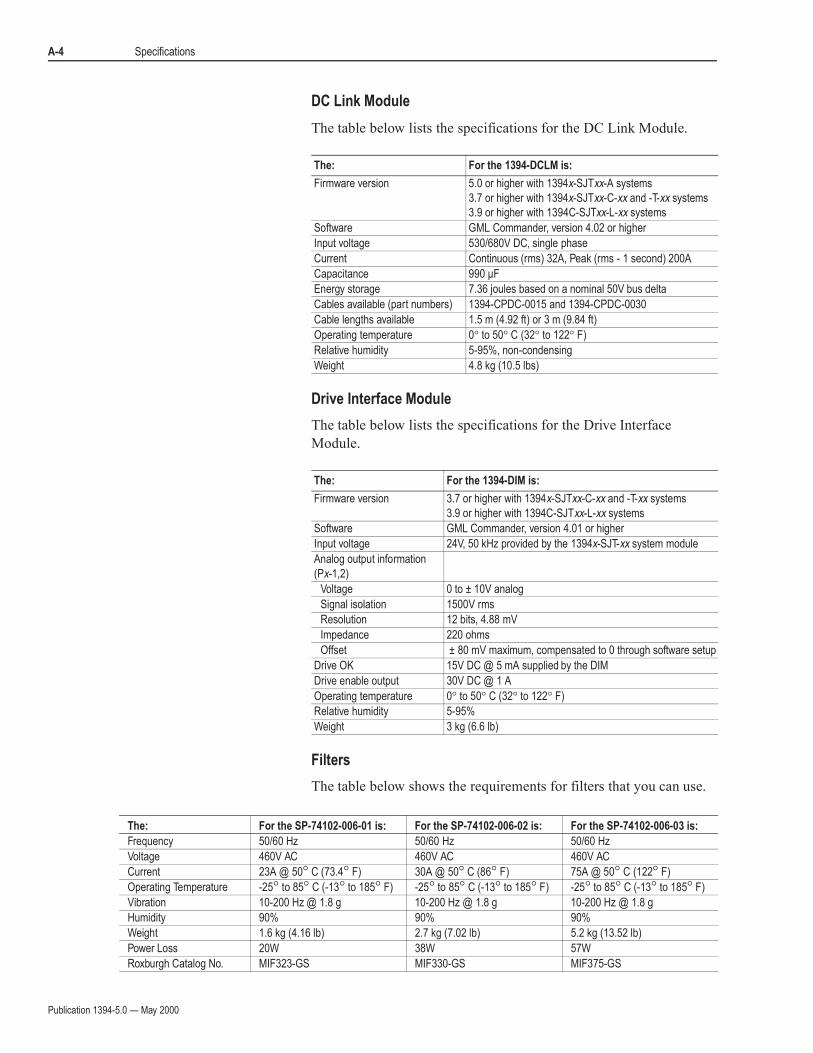
DC Link Module
The table below lists the specifications for the DC Link Module.
Drive Interface Module
The table below lists the specifications for the Drive Interface
Module.
Filters
The table below shows the requirements for filters that you can use.
The: For the 1394-DCLM is:
Firmware version 5.0 or higher with 1394x-SJTxx-A systems
3.7 or higher with 1394x-SJTxx-C-xx and -T-xx systems
3.9 or higher with 1394C-SJTxx-L-xx systems
Software GML Commander, version 4.02 or higher
Input voltage 530/680V DC, single phase
Current Continuous (rms) 32A, Peak (rms - 1 second) 200A
Capacitance 990 µF
Energy storage 7.36 joules based on a nominal 50V bus delta
Cables available (part numbers) 1394-CPDC-0015 and 1394-CPDC-0030
Cable lengths available 1.5 m (4.92 ft) or 3 m (9.84 ft)
Operating temperature 0° to 50° C (32° to 122° F)
Relative humidity 5-95%, non-condensing
Weight 4.8 kg (10.5 lbs)
The: For the 1394-DIM is:
Firmware version 3.7 or higher with 1394x-SJTxx-C-xx and -T-xx systems
3.9 or higher with 1394C-SJTxx-L-xx systems
Software GML Commander, version 4.01 or higher
Input voltage 24V, 50 kHz provided by the 1394x-SJT-xx system module
Analog output information
(Px-1,2)
Voltage 0 to ± 10V analog
Signal isolation 1500V rms
Resolution 12 bits, 4.88 mV
Impedance 220 ohms
Offset ± 80 mV maximum, compensated to 0 through software setup
Drive OK 15V DC @ 5 mA supplied by the DIM
Drive enable output 30V DC @ 1 A
Operating temperature 0° to 50° C (32° to 122° F)
Relative humidity 5-95%
Weight 3 kg (6.6 lb)
The: For the SP-74102-006-01 is: For the SP-74102-006-02 is: For the SP-74102-006-03 is:
Frequency 50/60 Hz 50/60 Hz 50/60 Hz
Voltage 460V AC 460V AC 460V AC
Current 23A @ 50° C (73.4° F) 30A @ 50° C (86° F) 75A @ 50° C (122° F)
Operating Temperature -25° to 85° C (-13° to 185° F) -25° to 85° C (-13° to 185° F) -25° to 85° C (-13° to 185° F)
Vibration 10-200 Hz @ 1.8 g 10-200 Hz @ 1.8 g 10-200 Hz @ 1.8 g
Humidity 90% 90% 90%
Weight 1.6 kg (4.16 lb) 2.7 kg (7.02 lb) 5.2 kg (13.52 lb)
Power Loss 20W 38W 57W
Roxburgh Catalog No. MIF323-GS MIF330-GS MIF375-GS

Publication 1394-5.0 — May 2000
Specifications A-5
User-Supplied Contactor (M1)
The table below shows the requirements for the contactor that you
must supply.
User-Supplied Line Input Fusing
The table below shows the requirements for the input fusing that you
must supply.
User-Supplied 24V Logic Input Power
The table below shows the requirements for the 24V logic input
power that you must supply.
The contactor: For the 1394-SJT05 and
-SJT10 (Series A and B) is:
For the 1394C-SJT05 and
-SJT10 (Series C) is:
For the 1394x-SJT22 is:
Rating 600V AC, 43A1 600V AC, 23A 600V AC, 37A
Recommended
types:
AC Coil Operation Allen-Bradley 100-C43x102,3 Allen-Bradley 100-C23x102,3 Allen-Bradley 100-C37x102,3
DC Coil Operation Allen-Bradley 100-C43Zx102 Allen-Bradley 100-C23Zx102 Allen-Bradley 100-C37Zx102
1 Consider using a 60A contactor when the total capacitance of the axis modules is greater than 880 µF. 2 x indicates coil voltage.3 A surge suppressor is required.
The Recommended type of fuse for: Is: Rating
1394-SJT05 systems Series A and B Bussmann FRS-R-20A or
equivalent
600V AC, 20A
1394C-SJT05 systems Series C Bussmann KTK-R-20 or
equivalent
600V AC, 20A
Bussmann LPJ-SP 20 or
equivalent
600V AC, 20A
1394-SJT10 systems Series A and B Bussmann FRS-R-30A or
equivalent
600V AC, 30A
1394C-SJT10 systems Series C Bussmann KTK-R-30 or
equivalent
600V AC, 30A
Bussmann LPJ-SP 30 or
equivalent
600V AC, 30A
1394x-SJT22 systems Bussmann FRS-R-35 or
equivalent
600V AC, 35A
Bussmann LPS-RK-SP 40
or equivalent
600V AC, 40A
Bussmann LPJ-SP 45 or
equivalent
600V AC, 45A
24V logic input
voltage
Frequency Current1 Recommended Fuse
If you have: The current draw for user-
supplied power supply
must not exceed:
19-28V AC RMS,
single phase or50/60 Hz
1 axis 3.5A
Bussmann MDA-15
or equivalent
2 axis 4.4A
18.75-31.25V DC 3 axis 5.2A
4 axis 6.0A1 The power supply should be rated for 15A or greater inrush current upon power up.

Publication 1394-5.0 — May 2000
A-6 Specifications
Input Transformer for 24V Control Power
You can use any general purpose transformer with the following
ratings.
If the input volt-amperes is more than 350 VA, adjust the load
regulation to make the transformer leakage the same as or greater than
the 250 VA transformer with 2% regulation.
User-Supplied 5V Auxiliary Encoder Power Supply
The table below shows the requirements for the 5V encoder that you
can supply. If you use an encoder that requires more than 5V, you still
need a 5V power supply for the 1394 encoder board electronics at a
rating of 0.325A (applies to 1394x-SJTxx-C, -L, and -T systems
only).
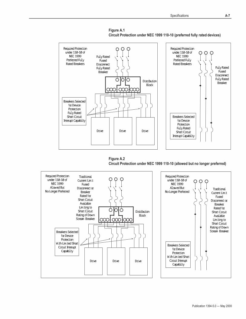
Circuit Breakers
While circuit breakers offer some convenience, there are limitations
for their use. Circuit breakers do not handle high current inrush as
well as fuses. The 1394 system needs to be protected by a device
having a short circuit interrupt current rating of the service capacity
provided or a maximum of 100,000A.
If an upstream circuit protection device is rated for the overload
current and short circuit rating, a supplementary circuit protection
device (such as the 1492) can be used as the only 1394 branch circuit
protection device. The upstream fully rated device let-through must
be less than or equal to the 10 kA interrupt rating of the 1492.
The wiring interconnection in Figure A.1 and Figure A.2 provide
examples of the needed protection and follows UL and NEC codes.
Full compliance is dependent on final wiring design and installation.
The requirements for: For a 480V system is: For a 360V system is:
Input volt-amperes 200 to 259 VA 200 to 259 VA
Input voltage 480V RMS 360V RMS
Output voltage 24V RMS 24V RMS
Load regulation 2 to 5% 2 to 5%
The: For 5V logic input power must be:
Rating 5V DC +/- 5%
Current 0.325A plus the requirement of each encoder used. For
example, if you use one encoder with a 0.2A
requirement, the supply required is 0.525A (0.325A +
0.2A = 0.525A)
Publication 1394-5.0 — May 2000
Specifications A-7
Figure A.1
Circuit Protection under NEC 1999 110-10 (preferred fully rated devices)
Figure A.2
Circuit Protection under NEC 1999 110-10 (allowed but no longer preferred)
Required Protectionunder 110-10 of
NEC 1999Preferred FullyRated Breakers
Fully RatedFused
DisconnectFully Rated
Breaker
Breakers Selectedfor DeviceProtectionFully Rated
Short CircuitInterupt Capability
Drive Drive Drive
DistributionBlock
Required Protectionunder 110-10 of
NEC 1999Preferred FullyRated Breakers
Fully RatedFused
DisconnectFully Rated
Breaker
Breakers Selectedfor DeviceProtectionFully RatedShort Circuit
Interupt Capability
Required Protectionunder 110-10 of
NEC 1999Allowed But
No Longer Preferred
TraditionalCurrent Limit
FusedDisconnect or
BreakerRated for
Short CircuitAvailable
Limiting toShort Circuit
Rating of DownStream Breaker
Breakers Selectedfor DeviceProtection
With Limited ShortCircuit Interupt
Capability
DistributionBlock
Required Protectionunder 110-10 of
NEC 1999Allowed But
No Longer Preferred
Breakers Selectedfor DeviceProtection
With Limited ShortCircuit Interupt
CapabilityDrive Drive Drive
TraditionalCurrent Limit
FusedDisconnect or
BreakerRated for
Short CircuitAvailable
Limiting toShort Circuit
Rating of DownStream Breaker
Publication 1394-5.0 — May 2000
A-8 Specifications
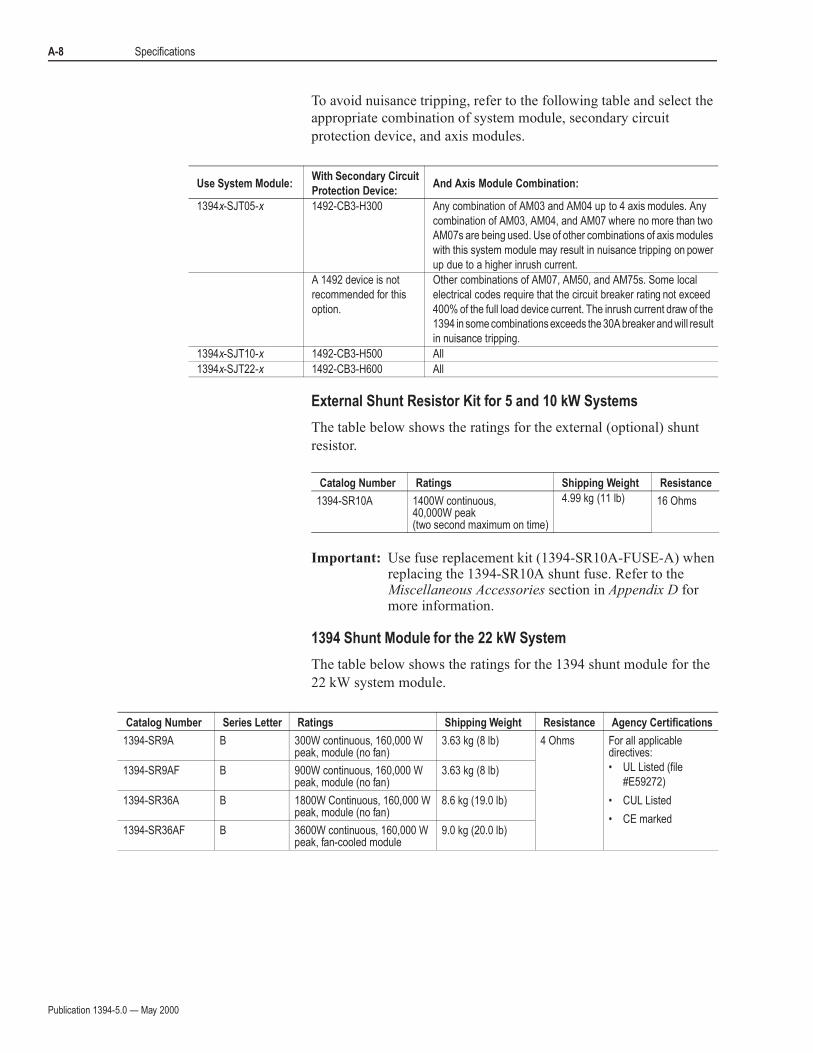
To avoid nuisance tripping, refer to the following table and select the
appropriate combination of system module, secondary circuit
protection device, and axis modules.
External Shunt Resistor Kit for 5 and 10 kW Systems
The table below shows the ratings for the external (optional) shunt
resistor.
Important: Use fuse replacement kit (1394-SR10A-FUSE-A) when replacing the 1394-SR10A shunt fuse. Refer to the Miscellaneous Accessories section in Appendix D for more information.
1394 Shunt Module for the 22 kW System
The table below shows the ratings for the 1394 shunt module for the
22 kW system module.
Use System Module:With Secondary Circuit
Protection Device:And Axis Module Combination:
1394x-SJT05-x 1492-CB3-H300 Any combination of AM03 and AM04 up to 4 axis modules. Any
combination of AM03, AM04, and AM07 where no more than two
AM07s are being used. Use of other combinations of axis modules
with this system module may result in nuisance tripping on power
up due to a higher inrush current.
A 1492 device is not
recommended for this
option.
Other combinations of AM07, AM50, and AM75s. Some local
electrical codes require that the circuit breaker rating not exceed
400% of the full load device current. The inrush current draw of the
1394 in some combinations exceeds the 30A breaker and will result
in nuisance tripping.
1394x-SJT10-x 1492-CB3-H500 All
1394x-SJT22-x 1492-CB3-H600 All
Catalog Number Ratings Shipping Weight Resistance
1394-SR10A 1400W continuous,40,000W peak(two second maximum on time)
4.99 kg (11 lb) 16 Ohms
Catalog Number Series Letter Ratings Shipping Weight Resistance Agency Certifications
1394-SR9A B 300W continuous, 160,000 W peak, module (no fan)
3.63 kg (8 lb) 4 Ohms For all applicable directives:
• UL Listed (file
#E59272)
• CUL Listed
• CE marked
1394-SR9AF B 900W continuous, 160,000 W peak, module (no fan)
3.63 kg (8 lb)
1394-SR36A B 1800W Continuous, 160,000 W peak, module (no fan)
8.6 kg (19.0 lb)
1394-SR36AF B 3600W continuous, 160,000 W peak, fan-cooled module
9.0 kg (20.0 lb)
Publication 1394-5.0 — May 2000
Specifications A-9
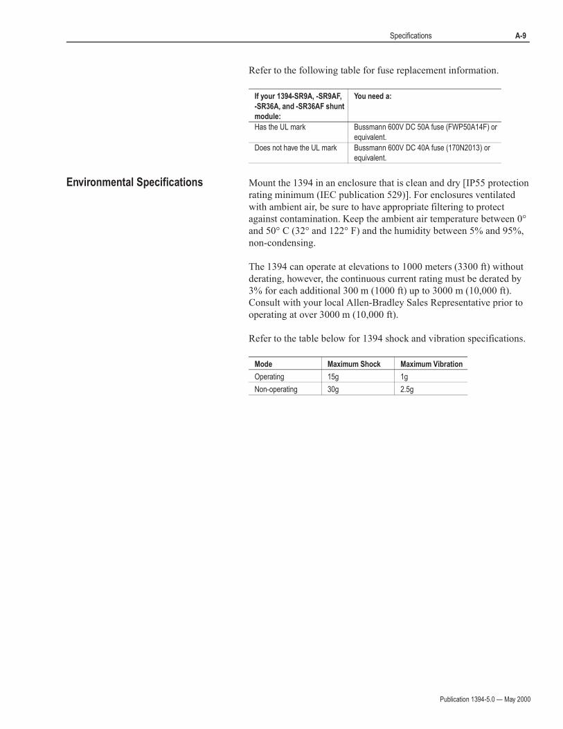
Refer to the following table for fuse replacement information.
Environmental Specifications Mount the 1394 in an enclosure that is clean and dry [IP55 protection
rating minimum (IEC publication 529)]. For enclosures ventilated
with ambient air, be sure to have appropriate filtering to protect
against contamination. Keep the ambient air temperature between 0°
and 50° C (32° and 122° F) and the humidity between 5% and 95%,
non-condensing.
The 1394 can operate at elevations to 1000 meters (3300 ft) without
derating, however, the continuous current rating must be derated by
3% for each additional 300 m (1000 ft) up to 3000 m (10,000 ft).
Consult with your local Allen-Bradley Sales Representative prior to
operating at over 3000 m (10,000 ft).
Refer to the table below for 1394 shock and vibration specifications.
If your 1394-SR9A, -SR9AF,
-SR36A, and -SR36AF shunt
module:
You need a:
Has the UL mark Bussmann 600V DC 50A fuse (FWP50A14F) or
equivalent.
Does not have the UL mark Bussmann 600V DC 40A fuse (170N2013) or
equivalent.
Mode Maximum Shock Maximum Vibration
Operating 15g 1g
Non-operating 30g 2.5g
Publication 1394-5.0 — May 2000
A-10 Specifications
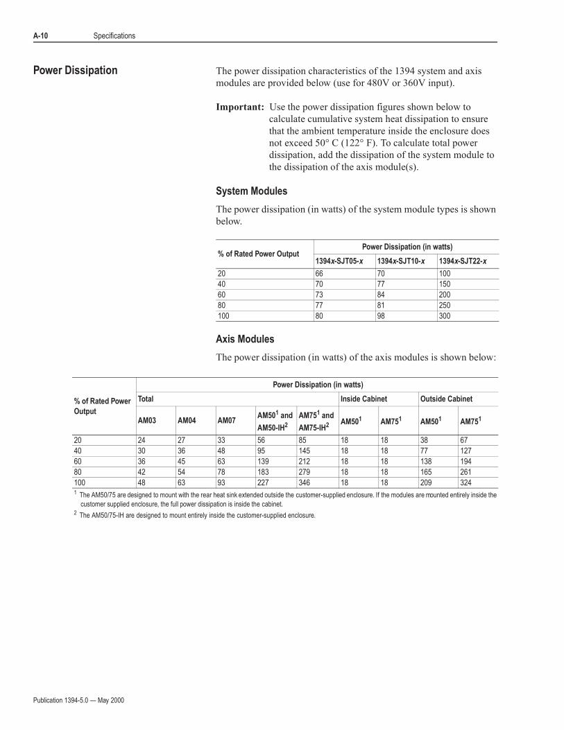
Power Dissipation The power dissipation characteristics of the 1394 system and axis
modules are provided below (use for 480V or 360V input).
Important: Use the power dissipation figures shown below to
calculate cumulative system heat dissipation to ensure
that the ambient temperature inside the enclosure does
not exceed 50° C (122° F). To calculate total power
dissipation, add the dissipation of the system module to
the dissipation of the axis module(s).
System Modules
The power dissipation (in watts) of the system module types is shown
below.
Axis Modules
The power dissipation (in watts) of the axis modules is shown below:
% of Rated Power OutputPower Dissipation (in watts)
1394x-SJT05-x 1394x-SJT10-x 1394x-SJT22-x
20 66 70 100
40 70 77 150
60 73 84 200
80 77 81 250
100 80 98 300
% of Rated Power
Output
Power Dissipation (in watts)
Total Inside Cabinet Outside Cabinet
AM03 AM04 AM07AM501 and
AM50-IH2
AM751 and
AM75-IH2 AM501 AM751 AM501 AM751
20 24 27 33 56 85 18 18 38 67
40 30 36 48 95 145 18 18 77 127
60 36 45 63 139 212 18 18 138 194
80 42 54 78 183 279 18 18 165 261
100 48 63 93 227 346 18 18 209 3241 The AM50/75 are designed to mount with the rear heat sink extended outside the customer-supplied enclosure. If the modules are mounted entirely inside the
customer supplied enclosure, the full power dissipation is inside the cabinet.2 The AM50/75-IH are designed to mount entirely inside the customer-supplied enclosure.

Publication 1394-5.0 — May 2000
Specifications A-11
DC Link Module
The power dissipation for the 1394-DCLM is shown below.
Drive Interface Module
The power dissipation for the 1394-DIM is shown below.
Internal Shunt Resistor for the 5 and 10 kW System (standard)
When the shunt resistor inside 1394x-SJT05 and 1394x-SJT10 system
module is active, some additional power will be dissipated at the
system module. Its maximum dissipation is 200W. Most applications
will use less than 10% of this capacity.
Communication Specifications The communication specifications are listed in the tables starting
below.
Encoder Input Specifications
The table below lists the encoder input specifications for the system
module (1394x-SJTxx-C-xx, -L-xx, and -T-xx systems).
The: For the 1394-DCLM is:
Power dissipation 4.225 W maximum
The: For the 1394-DIM is:
Power dissipation 30 W maximum
The: Is:
Rating of the internal shunt resistor 200W continuous, 40,000W peak (two second
maximum on time)
Resistance of the internal shunt resistor 16 ohms
The: Is:
Number of encoder inputs 4 (axis 0, 1, 2, and 3) for 1394x-SJTxx-C-xx and -T-xx systems
2 (axis 0 and 1) for 1394C-SJTxx-L-xx systems
Type of encoder input Incremental AB quadrature; optically isolated, differential
with marker channel
Encoder interface IC AM26LS32 or equivalent
Compatible encoder types Differential, TTl-level (5V DC) line driver outputs, with or
without marker
Decode modes 4 times quadrature, step/direction, count up/count down
Maximum encoder frequency 4,000,000 counts per second (4 MHz). This is equivalent to
a channel frequency of 1 MHz in 4x quadrature decode mode.
Input impedance 7 kohms minimum (each input)
Encoder power 5V DC @ 1A, user supplied
Publication 1394-5.0 — May 2000
A-12 Specifications
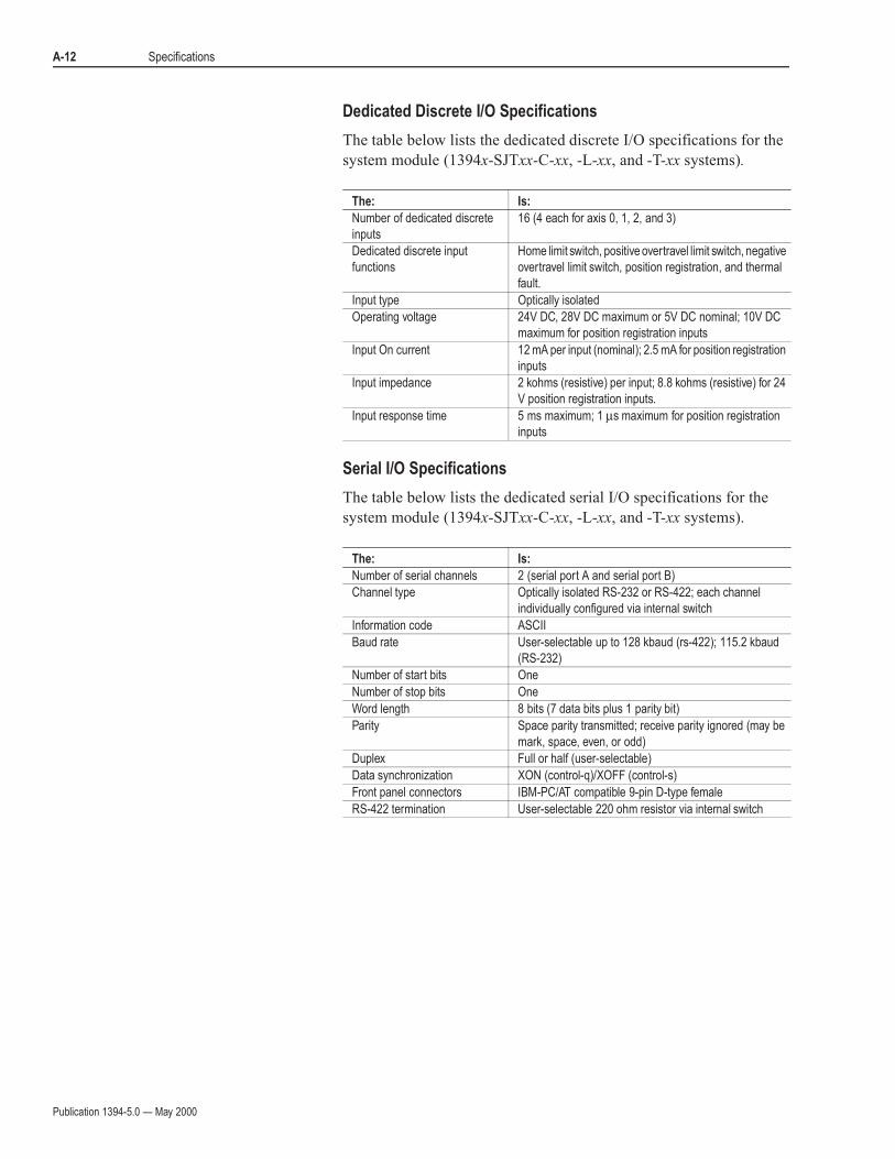
Dedicated Discrete I/O Specifications
The table below lists the dedicated discrete I/O specifications for the
system module (1394x-SJTxx-C-xx, -L-xx, and -T-xx systems).
Serial I/O Specifications
The table below lists the dedicated serial I/O specifications for the
system module (1394x-SJTxx-C-xx, -L-xx, and -T-xx systems).
The: Is:
Number of dedicated discrete
inputs
16 (4 each for axis 0, 1, 2, and 3)
Dedicated discrete input
functions
Home limit switch, positive overtravel limit switch, negative
overtravel limit switch, position registration, and thermal
fault.
Input type Optically isolated
Operating voltage 24V DC, 28V DC maximum or 5V DC nominal; 10V DC
maximum for position registration inputs
Input On current 12 mA per input (nominal); 2.5 mA for position registration
inputs
Input impedance 2 kohms (resistive) per input; 8.8 kohms (resistive) for 24
V position registration inputs.
Input response time 5 ms maximum; 1 µs maximum for position registration
inputs
The: Is:
Number of serial channels 2 (serial port A and serial port B)
Channel type Optically isolated RS-232 or RS-422; each channel
individually configured via internal switch
Information code ASCII
Baud rate User-selectable up to 128 kbaud (rs-422); 115.2 kbaud
(RS-232)
Number of start bits One
Number of stop bits One
Word length 8 bits (7 data bits plus 1 parity bit)
Parity Space parity transmitted; receive parity ignored (may be
mark, space, even, or odd)
Duplex Full or half (user-selectable)
Data synchronization XON (control-q)/XOFF (control-s)
Front panel connectors IBM-PC/AT compatible 9-pin D-type female
RS-422 termination User-selectable 220 ohm resistor via internal switch
Publication 1394-5.0 — May 2000
Specifications A-13
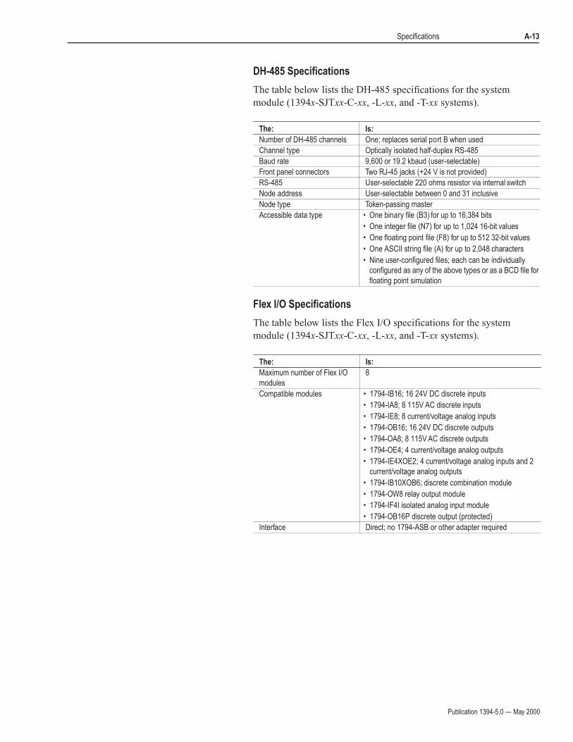
DH-485 Specifications
The table below lists the DH-485 specifications for the system
module (1394x-SJTxx-C-xx, -L-xx, and -T-xx systems).
Flex I/O Specifications
The table below lists the Flex I/O specifications for the system
module (1394x-SJTxx-C-xx, -L-xx, and -T-xx systems).
The: Is:
Number of DH-485 channels One; replaces serial port B when used
Channel type Optically isolated half-duplex RS-485
Baud rate 9,600 or 19.2 kbaud (user-selectable)
Front panel connectors Two RJ-45 jacks (+24 V is not provided)
RS-485 User-selectable 220 ohms resistor via internal switch
Node address User-selectable between 0 and 31 inclusive
Node type Token-passing master
Accessible data type • One binary file (B3) for up to 16,384 bits
• One integer file (N7) for up to 1,024 16-bit values
• One floating point file (F8) for up to 512 32-bit values
• One ASCII string file (A) for up to 2,048 characters
• Nine user-configured files; each can be individually
configured as any of the above types or as a BCD file for
floating point simulation
The: Is:
Maximum number of Flex I/O
modules
8
Compatible modules • 1794-IB16; 16 24V DC discrete inputs
• 1794-IA8; 8 115V AC discrete inputs
• 1794-IE8; 8 current/voltage analog inputs
• 1794-OB16; 16 24V DC discrete outputs
• 1794-OA8; 8 115V AC discrete outputs
• 1794-OE4; 4 current/voltage analog outputs
• 1794-IE4XOE2; 4 current/voltage analog inputs and 2
current/voltage analog outputs
• 1794-IB10XOB6; discrete combination module
• 1794-OW8 relay output module
• 1794-IF4I isolated analog input module
• 1794-OB16P discrete output (protected)
Interface Direct; no 1794-ASB or other adapter required
Publication 1394-5.0 — May 2000
A-14 Specifications
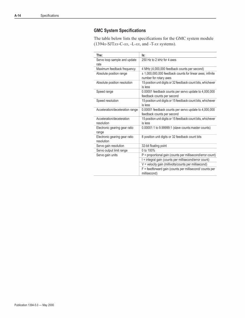
GMC System Specifications
The table below lists the specifications for the GMC system module
(1394x-SJTxx-C-xx, -L-xx, and -T-xx systems).
The: Is:
Servo loop sample and update
rate
250 Hz to 2 kHz for 4 axes
Maximum feedback frequency 4 MHz (4,000,000 feedback counts per second)
Absolute position range ± 1,000,000,000 feedback counts for linear axes; infinite
number for rotary axes
Absolute position resolution 15 position unit digits or 32 feedback count bits, whichever
is less
Speed range 0.00001 feedback counts per servo update to 4,000,000
feedback counts per second
Speed resolution 15 position unit digits or 15 feedback count bits, whichever
is less
Acceleration/deceleration range 0.00001 feedback counts per servo update to 4,000,000
feedback counts per second
Acceleration/deceleration
resolution
15 position unit digits or 15 feedback count bits, whichever
is less
Electronic gearing gear ratio
range
0.00001:1 to 9.99999:1 (slave counts:master counts)
Electronic gearing gear ratio
resolution
8 position unit digits or 32 feedback count bits
Servo gain resolution 32-bit floating point
Servo output limit range 0 to 100%
Servo gain units P = proportional gain (counts per millisecond/error count)
I = integral gain (counts per millisecond/error count)
V = velocity gain (millivolts/counts per millisecond)
F = feedforward gain (counts per millisecond/ counts per
millisecond)
Publication 1394-5.0 — May 2000
Specifications A-15
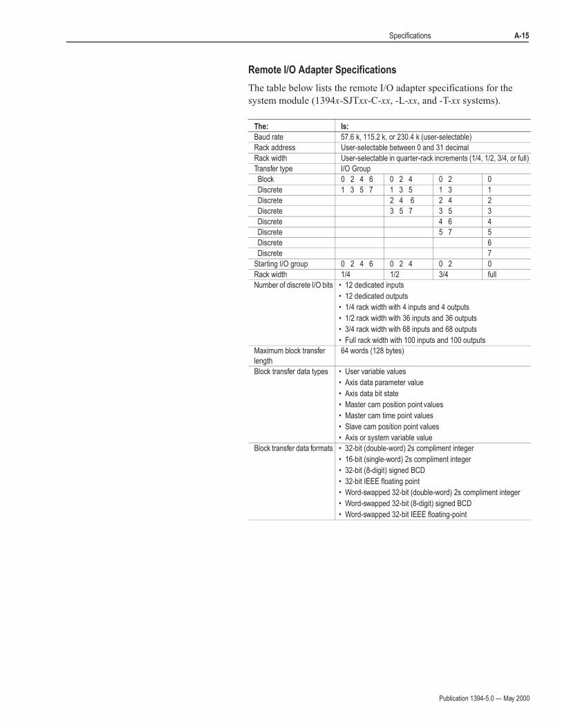
Remote I/O Adapter Specifications
The table below lists the remote I/O adapter specifications for the
system module (1394x-SJTxx-C-xx, -L-xx, and -T-xx systems).
The: Is:
Baud rate 57.6 k, 115.2 k, or 230.4 k (user-selectable)
Rack address User-selectable between 0 and 31 decimal
Rack width User-selectable in quarter-rack increments (1/4, 1/2, 3/4, or full)
Transfer type I/O Group
Block 0 2 4 6 0 2 4 0 2 0
Discrete 1 3 5 7 1 3 5 1 3 1
Discrete 2 4 6 2 4 2
Discrete 3 5 7 3 5 3
Discrete 4 6 4
Discrete 5 7 5
Discrete 6
Discrete 7
Starting I/O group 0 2 4 6 0 2 4 0 2 0
Rack width 1/4 1/2 3/4 full
Number of discrete I/O bits • 12 dedicated inputs
• 12 dedicated outputs
• 1/4 rack width with 4 inputs and 4 outputs
• 1/2 rack width with 36 inputs and 36 outputs
• 3/4 rack width with 68 inputs and 68 outputs
• Full rack width with 100 inputs and 100 outputs
Maximum block transfer
length
64 words (128 bytes)
Block transfer data types • User variable values
• Axis data parameter value
• Axis data bit state
• Master cam position point values
• Master cam time point values
• Slave cam position point values
• Axis or system variable value
Block transfer data formats • 32-bit (double-word) 2s compliment integer
• 16-bit (single-word) 2s compliment integer
• 32-bit (8-digit) signed BCD
• 32-bit IEEE floating point
• Word-swapped 32-bit (double-word) 2s compliment integer
• Word-swapped 32-bit (8-digit) signed BCD
• Word-swapped 32-bit IEEE floating-point

Publication 1394-5.0 — May 2000
A-16 Specifications
AxisLink Specifications
The table below lists the AxisLink specifications for the system
module (1394x-SJTxx-C-xx, -L-xx, and -T-xx systems).
The: Is:
Baud rate Standard and extended node
configuration
One megabit per second
Extended length configuration 500 kbits per second
Cable type Standard and extended node
configuration
Allen-Bradley 1770-CD RIO cable (Belden 9463 or
equivalent)
Extended length configuration Belden 9182, Carol C8014, or equivalent
Cable length Standard and extended node
configuration
25 m (82 ft) maximum. 1 m (3 ft) minimum between
controllers.
Extended length configuration 125 m (410 ft) maximum. 1 m (3 ft) minimum between
controllers.
Number of motion controllers Standard and extended length
configurations
8 maximum for a total of 32 possible axes
Extended node configuration 16 maximum for a total of 64 possible axes
Addressing Standard and extended length
configurations
User-selectable address via rotary selector switch on
front panel
Extended node configuration User-selectable address via GML
Number of virtual master axis Standard configuration 4 maximum; 1 per motion controller. Any axis on any
motion controller can be a virtual master axis to any
other motion controller. Each motion controller can
define a total of 2 separate axes on any other motion
controllers as virtual master axes, but only one can be
active any time. A total of 4 different axes can be active
as virtual master axes at any time.
Extended length and extended
node configurations
2 maximum; 1 per motion controller. Any axis on any
motion controller can be a virtual master axis to any
other motion controller. Each motion controller can
define a total of 2 separate axes on any other motion
controllers as virtual master axes, but only one can be
active any time. A total of two different axes can be
active as virtual master axes at any time.
Type of virtual master axes All configurations Command and actual. Each virtual master axis may be
defined to report its command or actual position.
Slave axes Standard and extended length
configuration
31 maximum total per virtual master axis (3 local + 4 x
7 other motion controllers = 31).
Extended node configuration 63 maximum total per virtual master axis (3 local + 4 x
15 other motion controllers = 63).
Number of discrete I/O All configurations 112 inputs maximum and 16 user-defined outputs per
motion controller. Any motion controller can read 16
discrete outputs of any other motion controller, giving a
maximum of 7 x 16 = 112 discrete inputs per motion
controller. For extended node configuration, discrete I/
O can still only be obtained from a maximum of 7 other
controllers (112 inputs maximum), not from all 15 other
controllers available in a 16 node maximum extended
node configuration.
Discrete I/O response All configurations ≤ 1 millisecond
Publication 1394-5.0 — May 2000
Specifications A-17
Dimensions Within this section, you will find dimensions for:
• The 1394 system module
• Axis modules (including 1394-DIM and 1394-DCLM)
• Filters
• External shunt modules
• Motors
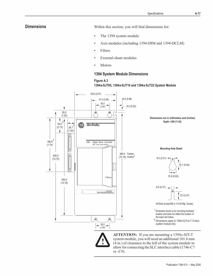
1394 System Module Dimensions
Figure A.3
1394x-SJT05, 1394x-SJT10 and 1394x-SJT22 System Module
!ATTENTION: If you are mounting a 1394x-SJT-T system module, you will need an additional 101.6 mm (4 in.) of clearance to the left of the system module to allow for connecting the SLC interface cable (1746-C7 or -C9).
All Slots Accept M6 or 1/4-20 Mtg. Screws
Depth = 280 (11.02)
50.0(1.97)
50.0(1.97)
25.0 (0.98)91.0 (3.58)
150.0 (5.91)
Mounting Hole Detail
Dimensions are in millimeters and (inches)
350.0(13.78)
385.0(15.16)
400.0(15.75)
26.0(1.02)
8.0 (0.31)
8.0 (0.31)
10.1 (0.40)
15.9 (0.63)
8.0 (0.32)
Status
Dimension shown is for mounting hardwarelocation and does not reflect the location of the lower slot radius.
12.0 (0.47)
196.9(7.75)
26.7(1.05)
54.0(2.13)
Fastnerlocation1
1
Dimensions apply to 1394x-SJTxx-T (Turbo)system module only.
2
2
2
2
DANGERRISK OF ELECTRICAL SHOCK. HIGH VOLTAGE MAYEXIST UP TO FIVE MINUTES AFTER REMOVING POWER.
Publication 1394-5.0 — May 2000
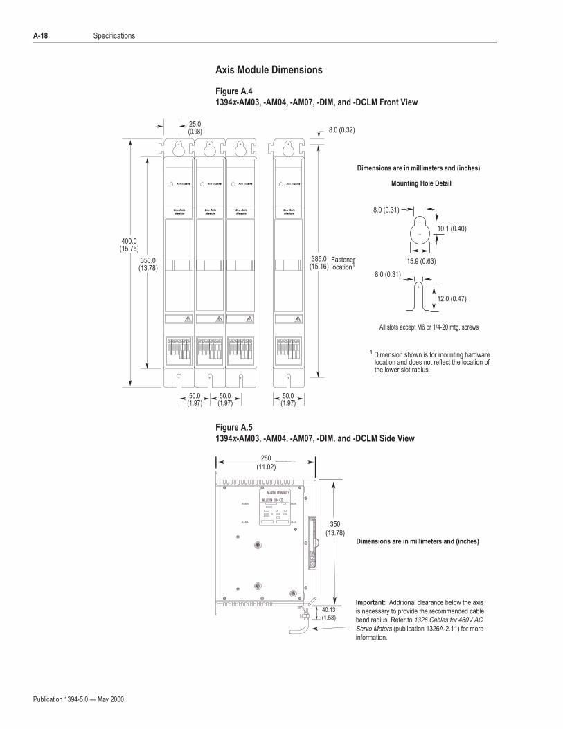
A-18 Specifications
Axis Module Dimensions
Figure A.4
1394x-AM03, -AM04, -AM07, -DIM, and -DCLM Front View
Figure A.5
1394x-AM03, -AM04, -AM07, -DIM, and -DCLM Side View
350.0(13.78)
400.0(15.75)
50.0(1.97)
25.0(0.98)
50.0(1.97)
50.0(1.97)
Dimensions are in millimeters and (inches)
All slots accept M6 or 1/4-20 mtg. screws
Mounting Hole Detail
12.0 (0.47)
385.0(15.16)
8.0 (0.31)
8.0 (0.31)
10.1 (0.40)
15.9 (0.63)
8.0 (0.32)
Fastenerlocation1
1 Dimension shown is for mounting hardware location and does not reflect the location of the lower slot radius.
350(13.78)
280(11.02)
Dimensions are in millimeters and (inches)
40.13
(1.58)
Important: Additional clearance below the axis is necessary to provide the recommended cable bend radius. Refer to 1326 Cables for 460V AC Servo Motors (publication 1326A-2.11) for more information.

Publication 1394-5.0 — May 2000
Specifications A-19
Figure A.6
1394x-AM50, -AM50-IH, -AM75, and -AM75-IH Axis Module Front View
Figure A.7
1394x-AM50 and -AM75 Axis Module Side View
350.0(13.78)
400.0(15.75)
37.5(1.48)
75.0(2.95)
75.0(2.95)
385.0(15.16)
8.0 (0.32)
When using the gasket provided with the axis module, torque the M6 to 7.9 N-m and the 1/4-20 to 75 lb-in.
All Slots Accept M6 or 1/4-20 Mtg. Screws
Depth = 280 (11.02)
Mounting Hole Detail
Dimensions are in millimeters and (inches)
8.0 (0.31)
8.0 (0.31)
10.1 (0.40)
15.9 (0.63)
12.0 (0.47)
Dimension shown is for mounting hardwarelocation and does not reflect the location of the lower slot radius.
1
1Fastenerlocation
Heat sink width onlyDimensions are in millimeters and (inches)
43.69
(1.72)105
(4.13)
338.1
(13.31)
385
(15.16)280
(11.02)
Important: Additional clearance below the axis is necessary to provide the recommended cable bend radius. Refer to 1326 Cables for 460V AC Servo Motors (publication 1326A-2.11) for more information.
Publication 1394-5.0 — May 2000
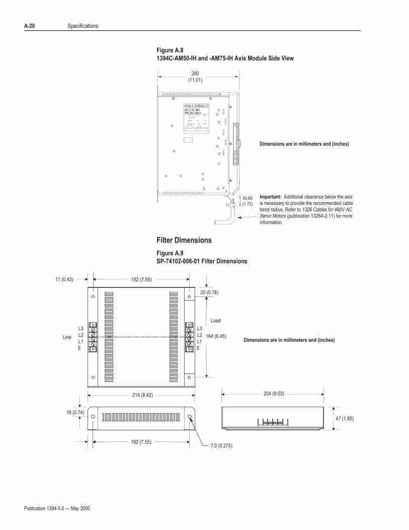
A-20 Specifications
Figure A.8
1394C-AM50-IH and -AM75-IH Axis Module Side View
Filter Dimensions
Figure A.9
SP-74102-006-01 Filter Dimensions
43.69
(1.72)
280(11.01)
Dimensions are in millimeters and (inches)
Important: Additional clearance below the axis is necessary to provide the recommended cable bend radius. Refer to 1326 Cables for 460V AC Servo Motors (publication 1326A-2.11) for more information.
Dimensions are in millimeters and (inches)
192 (7.55)
20 (0.78)
164 (6.45)
204 (8.03)
47 (1.85)
214 (8.42)
11 (0.43)
19 (0.74)
192 (7.55)7.0 (0.275)
L1
L2
L3
E
L1
L2
L3
E
Load
Line
Publication 1394-5.0 — May 2000
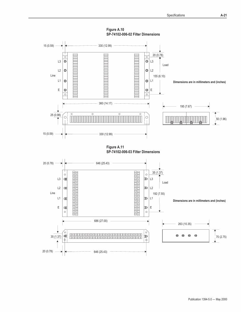
Specifications A-21
Figure A.10
SP-74102-006-02 Filter Dimensions
Figure A.11
SP-74102-006-03 Filter Dimensions
Dimensions are in millimeters and (inches)
330 (12.99)
20 (0.78)
155 (6.10)
360 (14.17)
15 (0.59)
195 (7.67)
50 (1.96)
25 (0.98)
15 (0.59) 330 (12.99)
L3
L2
L1
E
LoadL3
L2
L1
E
Line
Dimensions are in millimeters and (inches)
35 (1.37)
192 (7.55)
686 (27.00)
20 (0.78)
263 (10.35)
70 (2.75)35 (1.37)
20 (0.78) 646 (25.43)
L3
L2
L1
E
LoadL3
L2
L1
E
Line
646 (25.43)
Publication 1394-5.0 — May 2000
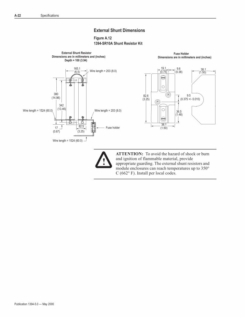
A-22 Specifications
External Shunt Dimensions
Figure A.12
1394-SR10A Shunt Resistor Kit
!ATTENTION: To avoid the hazard of shock or burn and ignition of flammable material, provide appropriate guarding. The external shunt resistors and module enclosures can reach temperatures up to 350°C (662° F). Install per local codes.
380(14.96)
342(13.46)
165.1(6.5) Wire length = 203 (8.0)
17(0.67)
Wire length = 1524 (60.0)
Wire length = 1524 (60.0)
Wire length = 203 (8.0)
82.5
(3.25)
Dimensions are in millimeters and (inches)Depth = 100 (3.94)
Fuse holder
++
++82.6(3.25)
36.5
(0.375 +/- 0.010)
(1.48)
9.5
19.1(0.75)
9.6(0.38)
38.1(1.50)
38.1(1.50)
Dimensions are in millimeters and (inches)
External Shunt Resistor Fuse Holder
Publication 1394-5.0 — May 2000
Specifications A-23
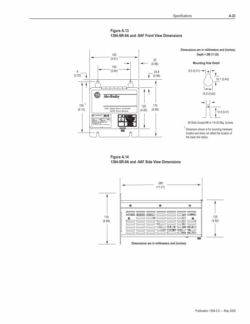
Figure A.13
1394-SR-9A and -9AF Front View Dimensions
Figure A.14
1394-SR-9A and -9AF Side View Dimensions
155(6.10)
175(6.89)
125(4.92)
8(0.32)
24.8(0.98)
25(0.98)
100(3.94)
150(5.91)
All Slots Accept M6 or 1/4-20 Mtg. Screws
Depth = 280 (11.02)
Mounting Hole Detail
Dimensions are in millimeters and (inches)
8.0 (0.31)
10.1 (0.40)
15.9 (0.63)
12.0 (0.47)
Dimension shown is for mounting hardwarelocation and does not reflect the location of the lower slot radius.
BULLETIN 1394 300W SHUNT MODULE
ALLEN-BRADLEY
FOR USE WITH 1394-SJT22-X SYSTEM MODULE
CAT. PART SER.
INPUT DC INPUT ACFOR FUSE REPLACEMENT USE:BUSSMAN CAT. NO.
R
1394 Digital Servo Controller
300W Shunt Module
1
1
175(6.89)
280(11.01)
125(4.92)
Dimensions are in millimeters and (inches)

Publication 1394-5.0 — May 2000
A-24 Specifications
Figure A.15
1394-SR-36A and -36AF Front View Dimensions
Figure A.16
1394-SR-36A and -36AF Side View Dimensions
400(15.75)
385.0(15.16)
(fastener location)
350(13.78)
8(0.32)
150(5.91)
100(3.94)
25(0.98)
24.8(0.98)
All Slots Accept M6 or 1/4-20 Mtg. Screws
Depth = 280 (11.02)
Mounting Hole Detail
Dimensions are in millimeters and (inches)
8.0 (0.31)
10.1 (0.40)
15.9 (0.63)
12.0 (0.47)
Dimension shown is for mounting hardwarelocation and does not reflect the location of the lower slot radius.
BULLETIN 1394 3600W SHUNT MODULE
ALLEN-BRADLEY
FOR USE WITH 1394-SJT22-X SYSTEM MODULE
CAT. PART SER.
INPUT DC INPUT AC
FOR FUSE REPLACEMENT USE:BUSSMAN CAT. NO.
R
1394 Digital Servo Controller3600W Shunt Module
1
1
400(15.75)
350(13.78)
280(11.01)
Dimensions are in millimeters and (inches)
Publication 1394-5.0 — May 2000
Specifications A-25
Motor Dimensions
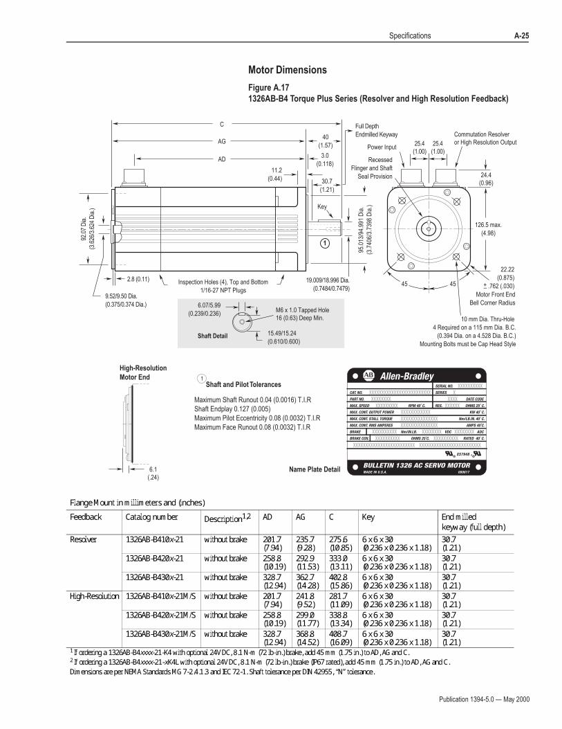
Figure A.17
1326AB-B4 Torque Plus Series (Resolver and High Resolution Feedback)
AD
AG
C
40
(1.57)
Key
45 45
Recessed
Flinger and Shaft
Seal Provision
126.5 max.
(4.98)
24.4(0.96)
25.4(1.00)
25.4(1.00)
95.0
13/9
4.99
1 D
ia.
(3.7
406/
3.73
98 D
ia.)
19.009/18.996 Dia.
(0.7484/0.7479)
3.0
(0.118)11.2
(0.44)
9.52/9.50 Dia.
(0.375/0.374 Dia.)
92.0
7 D
ia.
(3.6
26/3
.624
Dia
.)
Power Input
Commutation Resolveror High Resolution Output
2.8 (0.11) Inspection Holes (4), Top and Bottom
1/16-27 NPT Plugs
10 mm Dia. Thru-Hole
4 Required on a 115 mm Dia. B.C.
(0.394 Dia. on a 4.528 Dia. B.C.)
Mounting Bolts must be Cap Head Style
M6 x 1.0 Tapped Hole16 (0.63) Deep Min.
6.07/5.99
(0.239/0.236)
15.49/15.24
(0.610/0.600)Shaft Detail
30.7
(1.21)
Full Depth
Endmilled Keyway
1
Motor Front End
Bell Corner Radius
22.22
(0.875)
.762 (.030)+_
Maximum Shaft Runout 0.04 (0.0016) T.I.R
Shaft Endplay 0.127 (0.005)
Maximum Pilot Eccentricity 0.08 (0.0032) T.I.R
Maximum Face Runout 0.08 (0.0032) T.I.R
Name Plate Detail
Shaft and Pilot Tolerances
High-Resolution
Motor End 1
6.1(.24)
Flange Mount in millimeters and (inches)Feedback Catalog number Description1,2 AD AG C Key End milled
keyway (full depth)Resolver 1326AB-B410x-21 without brake 201.7(7.94) 235.7(9.28) 275.6(10.85) 6 x 6 x 30(0.236 x 0.236 x 1.18) 30.7(1.21)
1326AB-B420x-21 without brake 258.8(10.19) 292.9(11.53) 333.0(13.11) 6 x 6 x 30(0.236 x 0.236 x 1.18) 30.7(1.21)1326AB-B430x-21 without brake 328.7(12.94) 362.7(14.28) 402.8(15.86) 6 x 6 x 30(0.236 x 0.236 x 1.18) 30.7(1.21)
High-Resolution 1326AB-B410x-21M/S without brake 201.7(7.94) 241.8(9.52) 281.7(11.09) 6 x 6 x 30(0.236 x 0.236 x 1.18) 30.7(1.21)1326AB-B420x-21M/S without brake 258.8(10.19) 299.0(11.77) 338.8(13.34) 6 x 6 x 30(0.236 x 0.236 x 1.18) 30.7(1.21)1326AB-B430x-21M/S without brake 328.7(12.94) 368.8(14.52) 408.7(16.09) 6 x 6 x 30(0.236 x 0.236 x 1.18) 30.7(1.21)
1 If ordering a 1326AB-B4xxxx-21-K4 with optional 24V DC, 8.1 N-m (72 lb-in.) brake, add 45 mm (1.75 in.) to AD, AG and C.2 If ordering a 1326AB-B4xxxx-21-xK4L with optional 24V DC, 8.1 N-m (72 lb-in.) brake (IP67 rated), add 45 mm (1.75 in.) to AD, AG and C.Dimensions are per NEMA Standards MG 7-2.4.1.3 and IEC 72-1. Shaft tolerance per DIN 42955, “N” tolerance.

Publication 1394-5.0 — May 2000
A-26 Specifications
Figure A.18
1326AB-B5 Torque Plus Series (Resolver and High Resolution Feedback)
AD
AG
C
50
(1.97)
Key
45 45
163.6 max.
(6.44)
25.4(1.00)
25.4(1.00)
25.4(1.00)
130.
014/
129.
989
Dia
.
(5.1
186/
5.11
76 D
ia.)
24.009/23.996 Dia.
(0.9452/0.9447)
3.5
(0.138)15.0
(0.59)
9.52/9.50 Dia.
(0.3750/0.3745 Dia.)
130.
20/1
30.1
5 D
ia.
(5.1
26/5
.124
Dia
.)
Power Input
2.0 (0.079)
8.08/8.00
(0.318/0.315)
19.99/19.74
(0.787/0.777)Shaft Detail
12 mm Dia. Thru - Hole
4 Required on a 165 mm Dia. B.C.
(0.472 Dia. on a 6.496 Dia. B.C.)
Mounting Bolts must be Cap Head Style
Inspection Holes (4), Top and Bottom
1/16-27 NPT Plugs
M8 x 1.25 Tapped Hole19 (0.75) Deep Min.
41
(1.61)
Full Depth
Endmilled Keyway
Recessed
Flinger and Shaft
Seal Provision
Commutation Resolveror High Resolution Output
1
AL
Motor Front End
Bell Corner Radius
31.75
(1.25)
.762 (.030)
M8 x 1.25Eyebolt Thread
+_
Name Plate Detail
Shaft and Pilot TolerancesHigh-Resolution
Motor End
Maximum Shaft Runout 0.05 (0.002) T.I.R
Shaft Endplay 0.127 (0.005)
Maximum Pilot Eccentricity 0.10 (0.004) T.I.R
Maximum Face Runout 0.10 (0.004) T.I.R
1
14.5(.57)
Flange Mount in millimeters and (inches)Feedback Catalog number Description1,2 AL AD AG C Key End milled keyway
(full depth)Resolver 1326AB-B515x-21 without brake N/A 244.1(9.61) 276.6(10.89) 326.6(12.86) 8 x 7 x 40(0.315 x 0.276 x 1.57) 41.0(1.61)
1326AB-B520x-21 without brake N/A 282.2(11.11) 314.7(12.39) 364.7(14.36) 8 x 7 x 40(0.315 x 0.276 x 1.57) 41.0(1.61)1326AB-B530x-21 without brake 187
(7.362)1,2 364.7(14.36) 397.3(15.64) 447.3(17.61) 8 x 7 x 40(0.315 x 0.276 x 1.57) 41.0(1.61)High-Resolution 1326AB-B515x-21M/S without brake N/A 244.1(9.61) 291.1(11.46) 341.1(13.43) 8 x 7 x 40(0.315 x 0.276 x 1.57) 41.0(1.61)
1326AB-B520x-21M/S without brake N/A 282.2(11.11) 329.2(12.96) 379.2(14.93) 8 x 7 x 40(0.315 x 0.276 x 1.57) 41.0(1.61)1326AB-B530x-21M/S without brake 187
(7.362)1,2 364.7(14.36) 411.7(16.21) 461.8(18.18) 8 x 7 x 40(0.315 x 0.276 x 1.57) 41.0(1.61)1 If ordering a 1326AB-B5xxxx-21-K5 with optional 24V DC, 13.6 N-m (120 lb-in.) brake, add 76.2 mm (3.0 in.) to AD, AG and C (38.1 mm (1.5 in.) to AL).2 If ordering a 1326AB-B5xxxx-21-xK5L with optional 24V DC, 13.6 N-m (120 lb-in.) brake (IP67 rated), add 76.2 mm (3.0 in.) to AD, AG and C (38.1 mm (1.5 in.) to AL).Dimensions are per NEMA Standards MG 7-2.4.1.3 and IEC 72-1. Shaft tolerance per DIN 42955,”N” tolerance.

Publication 1394-5.0 — May 2000
Specifications A-27
Figure A.19
1326AB-B7 Torque Plus Series (Resolver and High Resolution Feedback)
60
(2.36)
Key
45 45
207.5 max.
(8.17)
26.9(1.06)
28.7(1.13)
28.7(1.13)
180.
014/
179.
989
Dia
.
(7.0
872/
7.08
62 D
ia.)
32.018/32.002 Dia.
(1.2606/1.2599)
4.0
(0.157)20.6
(0.81)
9.52/9.50 Dia.
(0.3750/0.3745 Dia.)
173.
63/1
73.5
8 D
ia.
(6.8
36/6
.834
Dia
.)
Power Input
3.96 (0.156)
15 mm Dia. Thru - Hole
4 Required on a 215 mm Dia. B.C.
(0.590 Dia. on a 8.465 Dia. B.C.)
Mounting Bolts must be Cap Head Style
10.08/10.01
(0.397/0.394)
26.87 (1.058)Shaft Detail
M12 x 1.75 Tapped Hole28 (1.10) Deep Min.
Inspection Holes (4), Top and Bottom
1/16-27 NPT Plugs
50.8
(2.00)
Recessed
Flinger and Shaft
Seal Provision
Full Depth
Endmilled Keyway
1
Commutation Resolveror High Resolution OutputAD
AG
C
AL
Motor Front End
Bell Corner Radius
38.1
(1.5)
M8 x 1.25Eyebolt Thread
+_ .762 (.030)
High-Resolution
Motor End
Shaft and Pilot Tolerances1
Maximum Shaft Runout 0.05 (0.002) T.I.R
Shaft Endplay 0.127 (0.005)
Maximum Pilot Eccentricity 0.10 (0.004) T.I.R
Maximum Face Runout 0.10 (0.004) T.I.R
Name Plate Detail5.8(.23)
Flange Mount in millimeters and (inches)Feedback Catalog number Description1,2 AL AD AG C Key End milled
keyway (full depth)Resolver 1326AB-B720x-21 without brake 164.3 (6.468)1,2 324.6(12.78) 366.0(14.41) 426.0 (16.77) 10 x 8 x 50(0.39 x 0.31 x 1.97) 50.8(2.00)
1326AB-B730x-21 without brake 208.7 (8.218)1,2 413.5(16.28) 454.9(17.91) 514.9(20.27 10 x 8 x 50(0.39 x 0.31 x 1.97) 50.8(2.00)1326AB-B740x-21 without brake 253.2 (9.968)1,2 502.4(19.78) 543.8(21.41) 603.8(23.77) 10 x 8 x 50(0.39 x 0.31 x 1.97) 50.8(2.00)
High-Resolution 1326AB-B720x-21M/S without brake 164.3 (6.468)1,2 324.6(12.78) 371.9(14.64) 431.8(17.00) 10 x 8 x 50(0.39 x 0.31 x 1.97) 50.8(2.00)1326AB-B730x-21M/S without brake 208.7 (8.218)1,2 413.5(16.28) 460.8(18.14) 520.7(20.50 10 x 8 x 50(0.39 x 0.31 x 1.97) 50.8(2.00)1326AB-B740x-21M/S without brake 253.2 (9.968)1,2 502.4(19.78) 549.7(21.64) 609.6(24.00) 10 x 8 x 50(0.39 x 0.31 x 1.97) 50.8(2.00)
1 If ordering a 1326AB-B7xxxx-21-K7 with an optional 24V DC, 45.1 N-m (400 lb-in.) brake, add 76.2 mm (3.0 in.) to AD, AG and C (38.1 mm (1.5) to AL).2 If ordering a 1326AB-B7xxxx-21-xK7L with an optional 24V DC, 45.1 N-m (400 lb-in.) brake (IP67 rated), add 76.2 mm (3.0 in.) to AD, AG and C (38.1 mm (1.5) to AL).Dimensions are per NEMA Standards MG 7-2.4.1.3 and IEC 72-1. Shaft tolerance per DIN 42955,”N” tolerance.

Publication 1394-5.0 — May 2000
A-28 Specifications
Figure A.20
1326AS-B3 Series Servo Motor
!Shaft and Pilot TolerancesShaft Runout 0.025 (0.001) T.I.R
Shaft Endplay 0.025 (0.001)
Pilot Eccentricity 0.08 (0.0032) T.I.R
Maximum Face Runout 0.08 (0.0032) T.I.R
Shaft Detail
45 45
C
AG
AD
10.9
Key
20
5.00/4.979.525/9.500 Dia.(0.375/0.374)
(0.429)
(0.787)
(0.118)
(1.181)
(1.063)
89 sq.(3.50)
(0.197/0.196)M4 x 0.7 Tapped hole10 (0.39) Deep min.
Power Input
CommutationResolver Output
14.008/13.997(0.5515/0.5511)
76.1
8/76
.23
Dia
.(2
.999
/3.0
01)
80.0
12/7
9.99
3(3
.150
/3.1
49)
11.00/10.90(0.433/0.429)
50(1
.97)
43(1
.69)
23
(0.9
1)
7 mm Dia. Thru-Hole4 required on a 100 mm Dia. B.C.
1.53(0.060)
41(1.61)
1
30 0.5
3 0.2
27 0.3
Motor Front End
Cap Corner Radius
9.1
(.36)
+_ .254 (.010)
Name Plate Detail
Flange Mount in millimeters and (inches)
Catalog number Description1 AD AG C Key End milled
keyway (full depth)
1326AS-B310x-21 without brake 135
(5.32)
165
(6.50)
195
(7.68)
5 x 5 x 20
(0.197 x 0.197 x 0.79)
20
(0.79)
1326AS-B330x-21 without brake 186
(7.32)
216
(8.50)
246
(9.68)
5 x 5 x 20
(0.197 x 0.197 x 0.79)
20
(0.79)1 If you are ordering a 1326AS-B3xxxx-21-K3 with an optional 24V DC 2.26 N-m (20 lb-in.) brake, add 39 mm (1.54 in.) to AD, AG and C.
Dimensions are per NEMA Standards MG 7-2.4.1.3 and IEC 72-1. Shaft and pilot tolerances are per DIN 42955, N tolerance.
Publication 1394-5.0 — May 2000
Specifications A-29
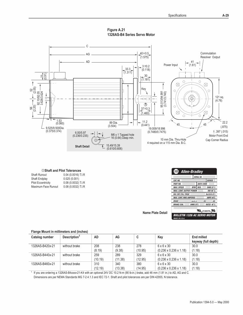
Figure A.21
1326AS-B4 Series Servo Motor
!Shaft and Pilot TolerancesShaft Runout 0.04 (0.0016) T.I.R
Shaft Endplay 0.025 (0.001)
Pilot Eccentricity 0.08 (0.0032) T.I.R
Maximum Face Runout 0.08 (0.0032) T.I.R
C
AG
AD
Key
40 0.5
30
(1.460)
(1.181)
(0.118)
(1.575)
11.2(0.441)
121 sq.(4.76)
(0.060)1.53
89 Dia.(3.504)
(0.375/0.374)9.525/9.500Dia.
Power Input
CommutationResolver Output
45 45
33.3(1.311)
95.0
13/9
4.99
1(3
.741
/3.7
40)
92.1
0/92
.05
3.62
6/3.
624
Shaft Detail
6.00/5.97(0.236/0.235) M6 x 1 Tapped hole
16 (0.64) Deep min.
15.49/15.39
10 mm Dia. Thru-Hole4 required on a 115 mm Dia. B.C.
(0.610/0.606)
56(2
.20)
52(2
.05)
23(0
.91)
19.009/18.996(0.7480/0.7475)
1
3 0.2
37 0.3
41(1.61)
Motor Front End
Cap Corner Radius
22.2
(.875)
+_ .397 (.015)
Name Plate Detail
Flange Mount in millimeters and (inches)
Catalog number Description1 AD AG C Key End milled
keyway (full depth)
1326AS-B420x-21 without brake 208
(8.19)
238
(9.38)
278
(10.95)
6 x 6 x 30
(0.236 x 0.236 x 1.18)
30.0
(1.18)
1326AS-B440x-21 without brake 259
(10.19)
289
(11.38)
329
(12.95)
6 x 6 x 30
(0.236 x 0.236 x 1.18)
30.0
(1.18)
1326AS-B460x-21 without brake 310
(12.19)
340
(13.38)
380
(14.95)
6 x 6 x 30
(0.236 x 0.236 x 1.18)
30.0
(1.18)1 If you are ordering a 1326AS-B4xxxx-21-K4 with an optional 24V DC 10.2 N-m (90 lb-in.) brake, add 46 mm (1.81 in.) to AD, AG and C.
Dimensions are per NEMA Standards MG 7-2.4.1.3 and IEC 72-1. Shaft and pilot tolerances are per DIN 42955, N tolerance.
Publication 1394-5.0 — May 2000
A-30 Specifications
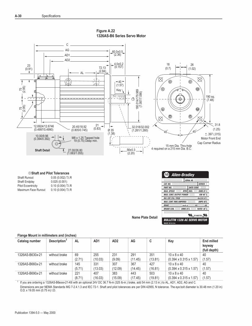
Figure A.22
1326AS-B6 Series Servo Motor
!Shaft and Pilot TolerancesShaft Runout 0.05 (0.002) T.I.R
Shaft Endplay 0.025 (0.001)
Pilot Eccentricity 0.10 (0.004) T.I.R
Maximum Face Runout 0.10 (0.004) T.I.R
Shaft Detail
10.00/9.96(0.394/0.392) M8 x 1.25 Tapped hole
19 (0.75) Deep min.
27.00/26.80(1.063/1.055)
4545
C
AG
AD1
AD2
190 sq.(7.48)
40(1.57)
180.
014/
179.
989
(7.0
87/7
.086
)
32.018/32.002(1.261/1.260)
21(0.83)
56±0.3(2.20)
Ø 35(1.38)
23(0.91)
75(2
.95)
75(2
.95)
12.6924/12.6746(0.4997/0.4990)
15 mm Dia. Thru-hole4 required on a 215 mm Dia. B.C.
4.0±0.2(0.157)
60.0±0.5(2.36)
26(1.02)
18(0.7)
20.45/18.92(0.805/0.745)
1
Key
72.13(2.84)
AL
Motor Front End
Cap Corner Radius
31.8
(1.25)
+_ .397 (.015)
Name Plate Detail
Flange Mount in millimeters and (inches)
Catalog number Description1 AL AD1 AD2 AG C Key End milled
keyway
(full depth)
1326AS-B630x-21 without brake 69
(2.71)
255
(10.03)
231
(9.09)
291
(11.45)
351
(13.81)
10 x 8 x 40
(0.394 x 0.315 x 1.57)
40
(1.57)
1326AS-B660x-21 without brake 145
(5.71)
331
(13.03)
307
(12.09)
367
(14.45)
427
(16.81)
10 x 8 x 40
(0.394 x 0.315 x 1.57)
40
(1.57)
1326AS-B690x-21 without brake 221
(8.71)
407
(16.03)
383
(15.09)
443
(17.45)
503
(19.81)
10 x 8 x 40
(0.394 x 0.315 x 1.57)
40
(1.57)1 If you are ordering a 1326AS-B6xxxx-21-K6 with an optional 24V DC 36.7 N-m (325 lb-in.) brake, add 54 mm (2.13 in.) to AL, AD1, AD2, AG and C.
Dimensions are per NEMA Standards MG 7-2.4.1.3 and IEC 72-1. Shaft and pilot tolerances are per DIN 42955, N tolerance. The eye bolt diameter is 30.48 mm (1.20 in) O.D. x 19.05 mm (0.75 in) I.D.
Publication 1394-5.0 — May 2000
Specifications A-31
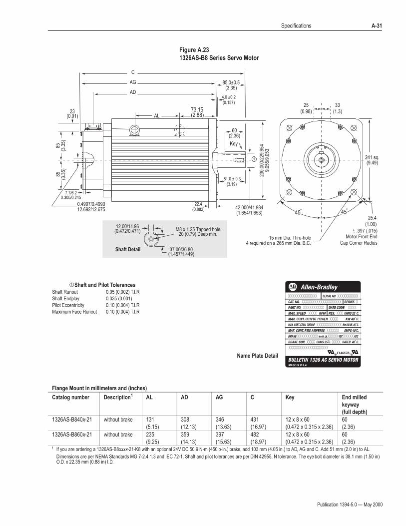
Figure A.23
1326AS-B8 Series Servo Motor
!Shaft and Pilot TolerancesShaft Runout 0.05 (0.002) T.I.R
Shaft Endplay 0.025 (0.001)
Pilot Eccentricity 0.10 (0.004) T.I.R
Maximum Face Runout 0.10 (0.004) T.I.R
Flange Mount in millimeters and (inches)
Catalog number Description1 AL AD AG C Key End milled
keyway
(full depth)
1326AS-B840x-21 without brake 131
(5.15)
308
(12.13)
346
(13.63)
431
(16.97)
12 x 8 x 60
(0.472 x 0.315 x 2.36)
60
(2.36)
1326AS-B860x-21 without brake 235
(9.25)
359
(14.13)
397
(15.63)
482
(18.97)
12 x 8 x 60
(0.472 x 0.315 x 2.36)
60
(2.36)1 If you are ordering a 1326AS-B8xxxx-21-K8 with an optional 24V DC 50.9 N-m (450lb-in.) brake, add 103 mm (4.05 in.) to AD, AG and C. Add 51 mm (2.0 in) to AL.
Dimensions are per NEMA Standards MG 7-2.4.1.3 and IEC 72-1. Shaft and pilot tolerances are per DIN 42955, N tolerance. The eye bolt diameter is 38.1 mm (1.50 in) O.D. x 22.35 mm (0.88 in) I.D.
Shaft Detail
241 sq.(9.49)
4545
C
AG
AD
60(2.36)
230.
000/
229.
954
9.05
5/9.
053
81.0 ± 0.3(3.19)
4.0 ±0.2(0.157)
22.4(0.882)
7.7/6.20.305/0.245
85.0±0.5(3.35)
42.000/41.984(1.654/1.653)
0.4997/0.499012.692/12.675
23(0.91)
12.00/11.96(0.472/0.471) M8 x 1.25 Tapped hole
20 (0.79) Deep min.
37.00/36.80(1.457/1.449)
15 mm Dia. Thru-hole4 required on a 265 mm Dia. B.C.
85(3
.35)
85(3
.35)
25(0.98)
33(1.3)
1
Key
73.15(2.88)AL
Motor Front EndCap Corner Radius
25.4(1.00)
+_ .397 (.015)
Name Plate Detail
Publication 1394-5.0 — May 2000
A-32 Specifications
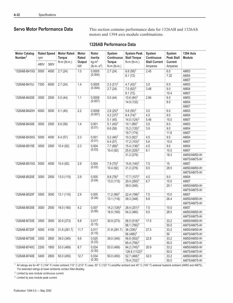
Servo Motor Performance Data This section contains performance data for 1326AB and 1326AS
motors and 1394 axis module combinations.
1326AB Performance Data
Motor Catalog
Number1Rated Speed
rpm
Motor Rated
Torque
N-m (lb-in.)
Motor
Rated
Output
kW
Rotor
Inertia
kg-m2
(lb-in.-s2)
System
Continuous
Torque
N-m (lb-in.)
System Peak
Stall Torque
N-m (lb-in.)
System
Continuous
Stall Current
Amperes
System
Peak Stall
Current
Amperes
1394 Axis
Module
480V 360V
1326AB-B410G 5000 4000 2.7 (24) 1.0 0.0005(0.004)
2.7 (24) 6.6 (58)3 2.45 6.0 AM03
8.1 (72) 7.32 AM04
AM07
1326AB-B410J 7250 6000 2.7 (24) 1.4 0.0005(0.004)
2.3 (21)2 4.7 (42)3 3.0 6.0 AM03
2.7 (24) 7.0 (62)3 3.48 9.0 AM04
8.1 (72) 10.4 AM07
1326AB-B420E 3000 2500 5.0 (44) 1.1 0.0008(0.007)
5.0 (44) 10.6 (94)3 2.84 6.0 AM03
14.9 (132) 8.0 AM04
AM07
1326AB-B420H 6000 5000 5.1 (45) 2.2 0.0008(0.007)
2.8 (25)2 5.6 (50)3 3.0 6.0 AM03
4.2 (37)2 8.4 (74)3 4.5 9.0 AM04
5.1 (45) 14.0 (124)3 5.46 15.0 AM07
1326AB-B430E 3000 2500 6.6 (58) 1.4 0.001 (0.01)
5.1 (45)2 10.1 (89)3 3.0 6.0 AM03
6.6 (58) 15.2 (135)3 3.9 9.0 AM04
19.7 (174) 11.6 AM07
1326AB-B430G 5000 4000 6.4 (57) 2.3 0.001 (0.01)
5.2 (46)2 10.3 (92)3 4.5 9.0 AM04
6.4 (57) 17.2 (153)3 5.6 15.0 AM07
1326AB-B515E 3000 2500 10.4 (92) 2.3 0.004(0.03)
7.7 (68)2 15.4 (136)3 4.5 9.0 AM04
10.4 (92) 25.6 (226)3 6.1 15.0 AM07
31.2 (276) 18.3 AM50/AM50-IH
AM75/AM75-IH
1326AB-B515G 5000 4000 10.4 (92) 2.9 0.004(0.03)
7.9 (70)2 15.8 (140)3 7.5 15 AM07
10.4 (92) 31.2 (276) 9.5 28.5 AM50/AM50-IH
AM75/AM75-IH
1326AB-B520E 3000 2500 13.0 (115) 2.9 0.005(0.04)
8.8 (78)2 17.7 (157)3 4.5 9.0 AM04
13.0 (115) 29.4 (260)3 6.7 15.0 AM07
39.0 (345) 20.1 AM50/AM50-IH
AM75/AM75-IH
1326AB-B520F 3500 3000 13.1 (116) 2.9 0.005(0.04)
11.2 (99)2 22.4 (198)3 7.5 15.0 AM07
13.1 (116) 39.3 (348) 8.8 26.4 AM50/AM50-IH
AM75/AM75-IH
1326AB-B530E 3000 2500 18.0 (160) 4.2 0.007 (0.06)
14.2 (126)2 28.4 (251)3 7.5 15.0 AM07
18.0 (160) 54.2 (480) 9.5 28.5 AM50/AM50-IH
AM75/AM75-IH
1326AB-B720E 3500 3000 30.9 (273) 6.8 0.017(0.15)
30.9 (273) 58.5 (518)3 17.5 33.2 AM50/AM50-IH
88.1 (780)3 50.0 AM75/AM75-IH
1326AB-B720F 5000 4100 31.8 (281.7) 11.7 0.017(0.15)
31.8 (281.7) 38 (336)3 27.5 33.2 AM50/AM50-IH
56 (495)3 50 AM75/AM75-IH
1326AB-B730E 3350 2800 39.0 (345) 9.6 0.025 (0.23)
39.0 (345) 56.8 (502)3 22.8 33.2 AM50/AM50-IH
85.4 (756)3 50.0 AM75/AM75-IH
1326AB-B740C 2200 1800 53.0 (469) 8.7 0.034(0.30)
53.0 (469) 84.2 (745)3 20.9 33.2 AM50/AM50-IH
126.8 (1122)3 50.0 AM75/AM75-IH
1326AB-B740E 3400 2800 50.0 (450) 12.7 0.034(0.30)
50.0 (450) 52.7 (466)3 32.0 33.2 AM50/AM50-IH
79.4 (702)3 50.0 AM75/AM75-IH1 All ratings are for 40° C (104° F) motor ambient,110° C (212° F) case, 50° C (122° F) amplifier ambient and 40° C (104° F) external heatsink ambient (AM50 and AM75).
For extended ratings at lower ambients contact Allen-Bradley.2 Limited by axis module continuous current.3 Limited by axis module peak current.
Publication 1394-5.0 — May 2000
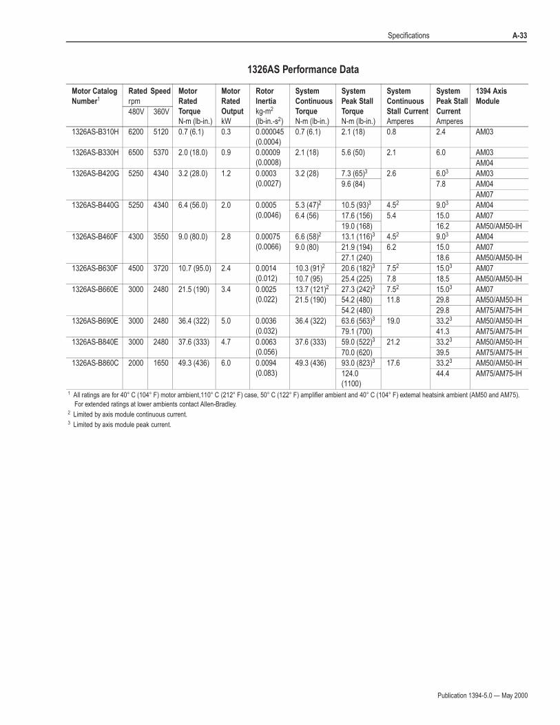
Specifications A-33
1326AS Performance Data
Motor Catalog
Number1
Rated Speed
rpm
Motor
Rated
Torque
N-m (lb-in.)
Motor
Rated
Output
kW
Rotor
Inertia
kg-m2
(lb-in.-s2)
System
Continuous
Torque
N-m (lb-in.)
System
Peak Stall
Torque
N-m (lb-in.)
System
Continuous
Stall Current
Amperes
System
Peak Stall
Current
Amperes
1394 Axis
Module
480V 360V
1326AS-B310H 6200 5120 0.7 (6.1) 0.3 0.000045
(0.0004)
0.7 (6.1) 2.1 (18) 0.8 2.4 AM03
1326AS-B330H 6500 5370 2.0 (18.0) 0.9 0.00009
(0.0008)
2.1 (18) 5.6 (50) 2.1 6.0 AM03
AM04
1326AS-B420G 5250 4340 3.2 (28.0) 1.2 0.0003
(0.0027)
3.2 (28) 7.3 (65)3 2.6 6.03 AM03
9.6 (84) 7.8 AM04
AM07
1326AS-B440G 5250 4340 6.4 (56.0) 2.0 0.0005
(0.0046)
5.3 (47)2 10.5 (93)3 4.52 9.03 AM04
6.4 (56) 17.6 (156) 5.4 15.0 AM07
19.0 (168) 16.2 AM50/AM50-IH
1326AS-B460F 4300 3550 9.0 (80.0) 2.8 0.00075
(0.0066)
6.6 (58)2 13.1 (116)3 4.52 9.03 AM04
9.0 (80) 21.9 (194) 6.2 15.0 AM07
27.1 (240) 18.6 AM50/AM50-IH
1326AS-B630F 4500 3720 10.7 (95.0) 2.4 0.0014
(0.012)
10.3 (91)2 20.6 (182)3 7.52 15.03 AM07
10.7 (95) 25.4 (225) 7.8 18.5 AM50/AM50-IH
1326AS-B660E 3000 2480 21.5 (190) 3.4 0.0025
(0.022)
13.7 (121)2 27.3 (242)3 7.52 15.03 AM07
21.5 (190) 54.2 (480) 11.8 29.8 AM50/AM50-IH
54.2 (480) 29.8 AM75/AM75-IH
1326AS-B690E 3000 2480 36.4 (322) 5.0 0.0036
(0.032)
36.4 (322) 63.6 (563)3 19.0 33.23 AM50/AM50-IH
79.1 (700) 41.3 AM75/AM75-IH
1326AS-B840E 3000 2480 37.6 (333) 4.7 0.0063
(0.056)
37.6 (333) 59.0 (522)3 21.2 33.23 AM50/AM50-IH
70.0 (620) 39.5 AM75/AM75-IH
1326AS-B860C 2000 1650 49.3 (436) 6.0 0.0094
(0.083)
49.3 (436) 93.0 (823)3 17.6 33.23 AM50/AM50-IH
124.0
(1100)
44.4 AM75/AM75-IH
1 All ratings are for 40° C (104° F) motor ambient,110° C (212° F) case, 50° C (122° F) amplifier ambient and 40° C (104° F) external heatsink ambient (AM50 and AM75).
For extended ratings at lower ambients contact Allen-Bradley.2 Limited by axis module continuous current.3 Limited by axis module peak current.

Publication 1394-5.0 — May 2000
Appendix D
Catalog Numbers
Understanding Catalog
Numbers
Catalog numbers consist of various components that make up a 1394
system. Each character of the catalog number identifies a specific version
or option for that component. The first four numbers represent the family
of products (for example, 1394). The remaining characters represent a
specific version or option of that module or family.
Determining Catalog Numbers
To help you to understand, we will provide an example of how to
determine a catalog number for a 1394 system module.
The beginning portion of the catalog number for all 1394 system modules
is 1394x-SJT (S for system module, J for 360/480V AC, 50/60 Hz, and T
for three-phase). In addition, you have the following options for which
you must make a selection:
The options must appear in the order shown.
1394series-SJT kw rating-option-RL option
For example, if you were to use the table in the following section 1394
System Modules to select the Series C, 5 kW, integrated motion controller,
with RIO and Axis Link, the catalog number would be:
1394C-SJT05-C-RL
When you combine all of the numbers, you create the catalog number for
the system module that you require.

Publication 1394-5.0 — May 2000
D-2 Catalog Numbers
System Modules 1394 System Module
9/440 System Module (Resolver based systems)
Note: 8520-C (Series C) system modules include Smart Power, improved terminations, and EMI filtering. Refer to 9/Series Integration and Maintenance Manual (publication 8520-6.2) for more information.
Bulletin
Number TypeInput
VoltageInput
PhasekW
Rating
Factory Installed
Options
1394
S = System module
T = three-phase
05 = 5 kW
10 = 10 kW
22 = 22 kW (not available with the -L option)
RL = With RIO and AxisLink (can only be ordered with the -C, -L, or -T options)
J = 360/480V AC, 50/60 Hz
A = With +/-10V DC analog input (HIM not included)
C = With IMC S Class integrated motion controller (supports four axes and four auxiliary encoder inputs)
D = With SERCOS network interface
L = With IMC S Class integrated motion controller (supports one axis and two auxiliary encoder inputs)
T = With IMC S Class Turbo integrated motion controller
E = With 9/Series interface
C = Series C enhancements
Blank = No Series C enhancements
1
Enhanced system modules have Smart Power, improved terminations, and EMI filtering. Enhancements available only with1394C-SJTxx-A, -C, -D, -L, and -T system modules.
1
Bulletin
Number
Number of
Axes
8520 C
5 = 5 kW
10 = 10 kW
22 = 22 kW
S = 9/440
1 = 1 axis
3 = 3 axes
4 = 4 axes
System
Type
kW
Rating
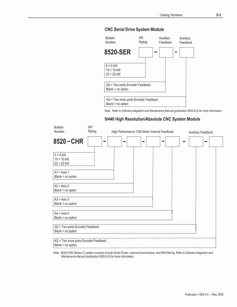
Publication 1394-5.0 — May 2000
Catalog Numbers D-3
CNC Serial Drive System Module
Note: Refer to 9/Series Integration and Maintenance Manual (publication 8520-6.2) for more information.
9/440 High Resolution/Absolute CNC System Module
Bulletin
Number
kW
Rating
8520-SER
Auxiliary
Feedback
4Q = Two more ports Encoder Feedback
Blank = no option
5 = 5 kW
10 = 10 kW
22 = 22 kW
2Q = Two ports Encoder Feedback
Blank = no option
Auxiliary
Feedback
Bulletin
Number
kW
Rating
8520 CHR
5 = 5 kW
10 = 10 kW
22 = 22 kW
High Performance 1326 Motor Internal Feedback Auxiliary Feedback
A1 = Axis 1
Blank = no option
A2 = Axis 2
Blank = no option
A4 = Axis 4
Blank = no option
A3 = Axis 3
Blank = no option
2Q = Two ports Encoder Feedback
Blank = no option
4Q = Two more ports Encoder Feedback
Blank = no option
Note: 8520-CHR (Series C) system modules include Smart Power, improved terminations, and EMI filtering. Refer to 9/Series Integration and Maintenance Manual (publication 8520-6.2) for more information.
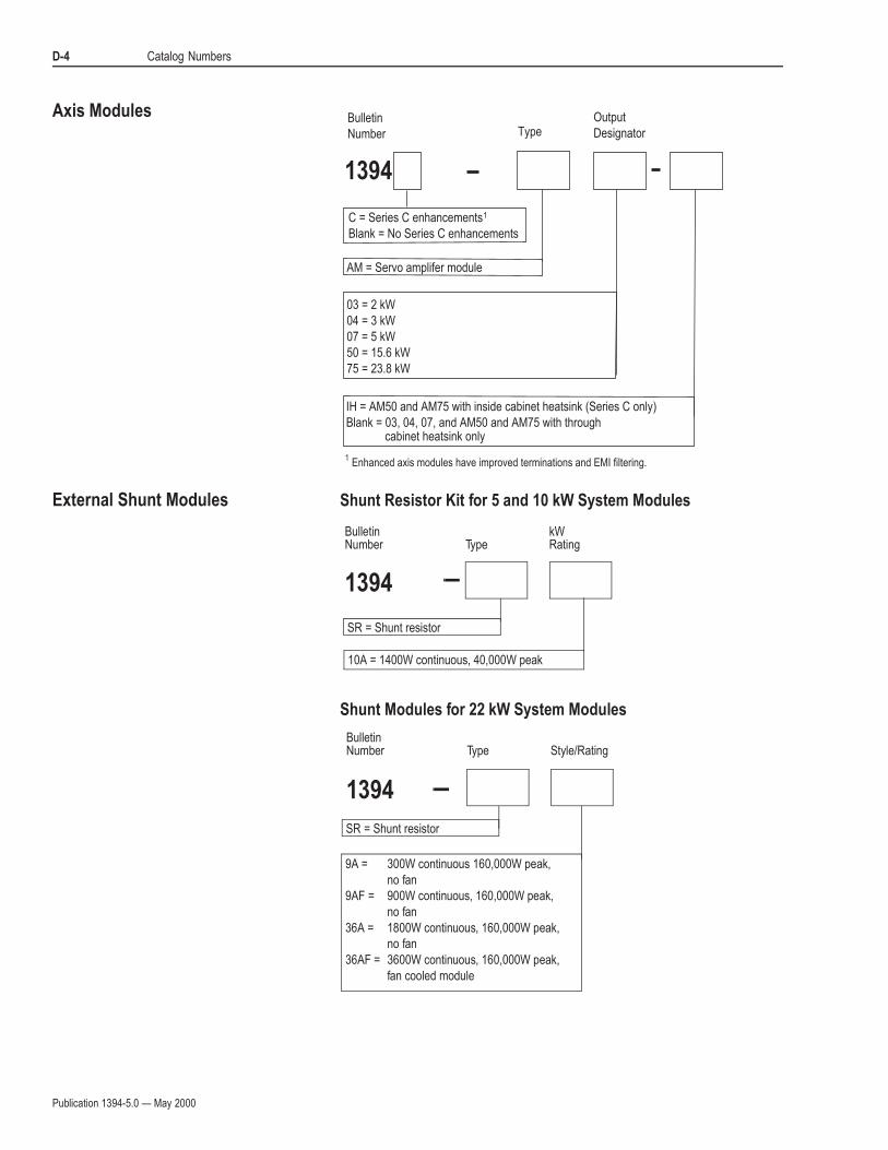
Publication 1394-5.0 — May 2000
D-4 Catalog Numbers
Axis Modules
External Shunt Modules Shunt Resistor Kit for 5 and 10 kW System Modules
Shunt Modules for 22 kW System Modules
03 = 2 kW
04 = 3 kW
07 = 5 kW
50 = 15.6 kW
75 = 23.8 kW
Bulletin
Number Type
1394
AM = Servo amplifer module
Output
Designator
C = Series C enhancements
Blank = No Series C enhancements
1
Enhanced axis modules have improved terminations and EMI filtering.1
IH = AM50 and AM75 with inside cabinet heatsink (Series C only)
Blank = 03, 04, 07, and AM50 and AM75 with through cabinet heatsink only
TypeBulletinNumber
1394
kW Rating
SR = Shunt resistor
10A = 1400W continuous, 40,000W peak
TypeBulletinNumber
1394
Style/Rating
SR = Shunt resistor
9A = 300W continuous 160,000W peak,
no fan
9AF = 900W continuous, 160,000W peak,
no fan
36A = 1800W continuous, 160,000W peak,
no fan
36AF = 3600W continuous, 160,000W peak,
fan cooled module
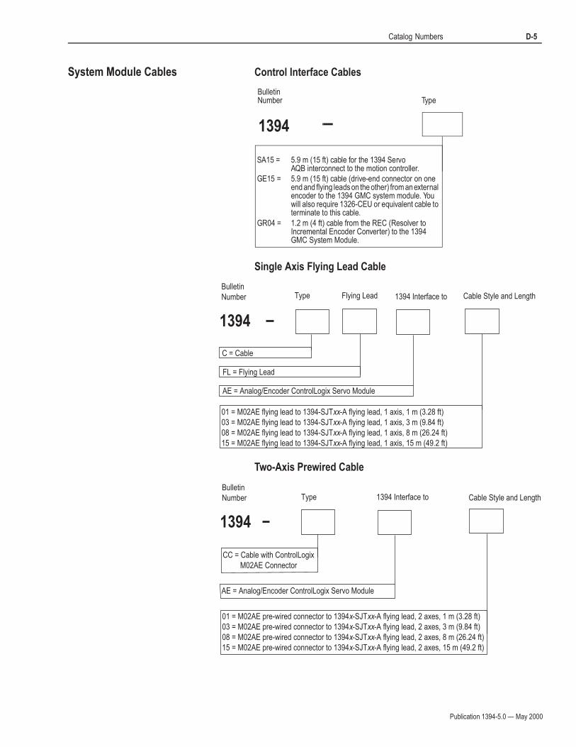
Publication 1394-5.0 — May 2000
Catalog Numbers D-5
System Module Cables Control Interface Cables
Single Axis Flying Lead Cable
Two-Axis Prewired Cable
BulletinNumber
1394
Type
SA15 = 5.9 m (15 ft) cable for the 1394 Servo AQB interconnect to the motion controller.
GE15 = 5.9 m (15 ft) cable (drive-end connector on oneend and flying leads on the other) from an externalencoder to the 1394 GMC system module. Youwill also require 1326-CEU or equivalent cable toterminate to this cable.
GR04 = 1.2 m (4 ft) cable from the REC (Resolver toIncremental Encoder Converter) to the 1394GMC System Module.
FL = Flying Lead
Bulletin
Number Type Cable Style and Length
1394
C = Cable
01 = M02AE flying lead to 1394-SJTxx-A flying lead, 1 axis, 1 m (3.28 ft)
03 = M02AE flying lead to 1394-SJTxx-A flying lead, 1 axis, 3 m (9.84 ft)
08 = M02AE flying lead to 1394-SJTxx-A flying lead, 1 axis, 8 m (26.24 ft)
15 = M02AE flying lead to 1394-SJTxx-A flying lead, 1 axis, 15 m (49.2 ft)
Flying Lead
AE = Analog/Encoder ControlLogix Servo Module
1394 Interface to
AE = Analog/Encoder ControlLogix Servo Module
Bulletin
Number Type Cable Style and Length
1394
CC = Cable with ControlLogix
M02AE Connector
01 = M02AE pre-wired connector to 1394x-SJTxx-A flying lead, 2 axes, 1 m (3.28 ft)
03 = M02AE pre-wired connector to 1394x-SJTxx-A flying lead, 2 axes, 3 m (9.84 ft)
08 = M02AE pre-wired connector to 1394x-SJTxx-A flying lead, 2 axes, 8 m (26.24 ft)
15 = M02AE pre-wired connector to 1394x-SJTxx-A flying lead, 2 axes, 15 m (49.2 ft)
1394 Interface to
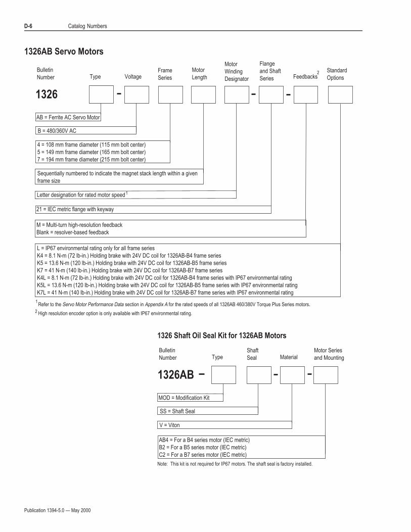
Publication 1394-5.0 — May 2000
D-6 Catalog Numbers
1326AB Servo Motors
1326 Shaft Oil Seal Kit for 1326AB Motors
Note: This kit is not required for IP67 motors. The shaft seal is factory installed.
Bulletin
Number Type VoltageFrame
Series
Motor
Length
Motor
Winding
Designator
Flange
and Shaft
Series FeedbacksStandard
Options
1326
AB = Ferrite AC Servo Motor
B = 480/360V AC
4 = 108 mm frame diameter (115 mm bolt center)
5 = 149 mm frame diameter (165 mm bolt center)
7 = 194 mm frame diameter (215 mm bolt center)
Sequentially numbered to indicate the magnet stack length within a given
frame size
Letter designation for rated motor speed1
21 = IEC metric flange with keyway
M = Multi-turn high-resolution feedback
Blank = resolver-based feedback
L = IP67 environmental rating only for all frame series
K4 = 8.1 N-m (72 lb-in.) Holding brake with 24V DC coil for 1326AB-B4 frame series
K5 = 13.6 N-m (120 lb-in.) Holding brake with 24V DC coil for 1326AB-B5 frame series
K7 = 41 N-m (140 lb-in.) Holding brake with 24V DC coil for 1326AB-B7 frame series
K4L = 8.1 N-m (72 lb-in.) Holding brake with 24V DC coil for 1326AB-B4 frame series with IP67 environmental rating
K5L = 13.6 N-m (120 lb-in.) Holding brake with 24V DC coil for 1326AB-B5 frame series with IP67 environmental rating
K7L = 41 N-m (140 lb-in.) Holding brake with 24V DC coil for 1326AB-B7 frame series with IP67 environmental rating
2
Refer to the Servo Motor Performance Data section in Appendix A for the rated speeds of all 1326AB 460/380V Torque Plus Series motors.1
2 High resolution encoder option is only available with IP67 environmental rating.
V = Viton
SS = Shaft Seal
Bulletin
Number TypeMotor Series
and Mounting
1326AB
MOD = Modification Kit
AB4 = For a B4 series motor (IEC metric)
B2 = For a B5 series motor (IEC metric)
C2 = For a B7 series motor (IEC metric)
Shaft
Seal Material
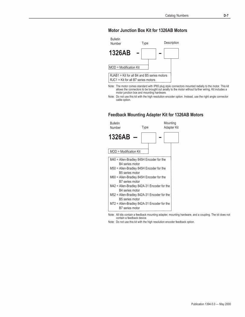
Publication 1394-5.0 — May 2000
Catalog Numbers D-7
Motor Junction Box Kit for 1326AB Motors
Note: The motor comes standard with IP65 plug style connectors mounted radially to the motor. This kit allows the connectors to be brought out axially to the motor without further wiring. Kit includes a motor junction box and mounting hardware.
Note: Do not use this kit with the high resolution encoder option. Instead, use the right angle connector cable option.
Feedback Mounting Adapter Kit for 1326AB Motors
Note: All kits contain a feedback mounting adapter, mounting hardware, and a coupling. The kit does not contain a feedback device.
Note: Do not use this kit with the high resolution encoder feedback option.
Bulletin
Number Type Description
1326AB
MOD = Modification Kit
RJAB1 = Kit for all B4 and B5 series motors
RJC1 = Kit for all B7 series motors
Bulletin
Number TypeMounting
Adapter Kit
1326AB
MOD = Modification Kit
M40 = Allen-Bradley 845H Encoder for the
B4 series motor
M50 = Allen-Bradley 845H Encoder for the
B5 series motor
M60 = Allen-Bradley 845H Encoder for the
B7 series motor
M42 = Allen-Bradley 842A-31 Encoder for the
B4 series motor
M52 = Allen-Bradley 842A-31 Encoder for the
B5 series motor
M72 = Allen-Bradley 842A-31 Encoder for the
B7 series motor

Publication 1394-5.0 — May 2000
D-8 Catalog Numbers
1326AS Servo Motors
1326 Shaft Oil Seal Kit for 1326AS Motors
TypeBulletinNumber
1326
VoltageFrameSeries
MotorLength
MotorWindingDesignator
Flangeand ShaftSeries
StandardOptions
AS = Rare Earth AC Servomotor
B = 460V AC
3 = 75 mm (Approximate stator size)4 = 100 mm (Approximate stator size)6 = 150 mm (Approximate stator size)8 = 200 mm (Approximate stator size)
Sequentially numbered to indicate the magnet stack length within a given frame size
Letter designation for rated motor speed1
21 = IEC metric flange with keyway
K3 = 2.26 N-m (20 lb-in.) Holding brake with 24V DC coil for 1326AS-B3 frame series
K4 = 10.2 N-m (90 lb-in.) Holding brake with 24V DC coil for 1326AS-B4 frame series
K6 = 36.7 N-m (325 lb-in.) Holding brake with 24V DC coil for 1326AS-B6 frame series
K8 = 50.9 N-m (450 lb-in.) Holding brake with 24V DC coil for 1326AS-B8 frame series
xxxxx = Special design options (factory assigned)
1 Refer to the Servo Motor Performance Data section in Appendix A for the rated speeds of the entire 1326AS Series family of motors.
BulletinNumber
0041
Series
5065 = Nitrile shaft seal for 1326AS-B3xxxx motors
5066 = Nitrile shaft seal for 1326AS-B4xxxx motors
5067 = Nitrile shaft seal for 1326AS-B6xxxx motors
5053-005 = Nitrile shaft seal for 1326AS-B8xxxx motors

Publication 1394-5.0 — May 2000
Catalog Numbers D-9
Motor Junction Box Kit for 1326AS Motors
Note: The motor comes standard with IP65 plug style connectors mounted radially to the motor. This kit allows the connectors to be brought out axially to the motor without further wiring. Kit includes a motor junction box and mounting hardware.
Feedback Mounting Adapter Kit for 1326AS Motors
Note: All kits contain a feedback mounting adapter, mounting hardware, and a coupling. The kit does not contain a feedback device.
BulletinNumber
1326AS
Type
RJ34 = Right angle junction box for B3 and B4 series motors.
Bulletin
Number TypeMounting
Adapter Kit
1326AS
MOD = Modification Kit
M32 = Allen-Bradley 842A-31 Encoder for the
B3 series motor
M42 = Allen-Bradley 842A-31 Encoder for the
B4 series motor
M62 = Allen-Bradley 842A-31 Encoder for the
B6 series motor
M82 = Allen-Bradley 842A-31 Encoder for the
B8 series motor
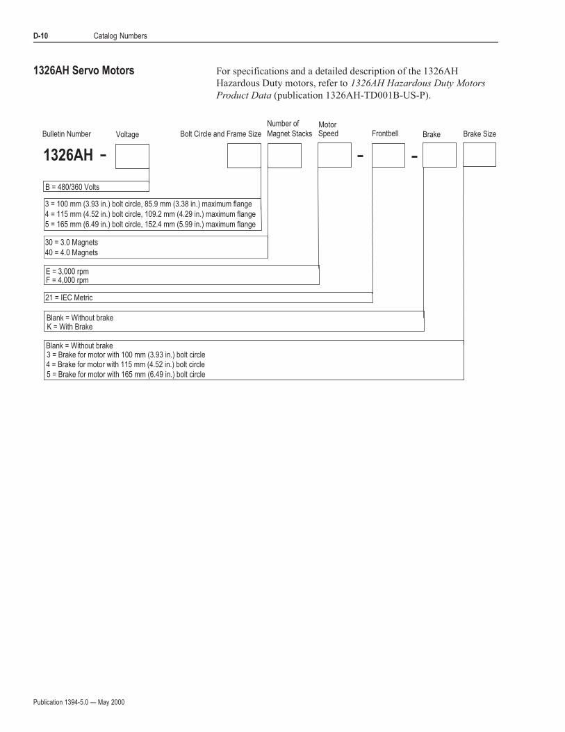
Publication 1394-5.0 — May 2000
D-10 Catalog Numbers
1326AH Servo Motors For specifications and a detailed description of the 1326AH
Hazardous Duty motors, refer to 1326AH Hazardous Duty Motors
Product Data (publication 1326AH-TD001B-US-P).
Bolt Circle and Frame Size
1326AH
B = 480/360 Volts
3 = 100 mm (3.93 in.) bolt circle, 85.9 mm (3.38 in.) maximum flange
4 = 115 mm (4.52 in.) bolt circle, 109.2 mm (4.29 in.) maximum flange
5 = 165 mm (6.49 in.) bolt circle, 152.4 mm (5.99 in.) maximum flange
Voltage
Number of
Magnet Stacks
E = 3,000 rpm
21 = IEC Metric
Blank = Without brakeK = With Brake
3 = Brake for motor with 100 mm (3.93 in.) bolt circle4 = Brake for motor with 115 mm (4.52 in.) bolt circle
5 = Brake for motor with 165 mm (6.49 in.) bolt circle
F = 4,000 rpm
Blank = Without brake
Brake Brake SizeFrontbellSpeedMotor
Bulletin Number
30 = 3.0 Magnets
40 = 4.0 Magnets

Publication 1394-5.0 — May 2000
Catalog Numbers D-11
Power and Feedback Cables Motor Power Cables
Bulletin
Number Type
1326
FunctionMotor SizeUsed On
Flex CableOption
ConnectorAccessory
IPRating
CableLength
C = Connector and cable assembly
P = Power connection
B1 = 1326AB-B4xxxx, -B5xxxx or 1326AS-B3xxxx, -B4xxxxC1 - 1326AB-B7xxxx, or 1326AS-B6xxxx, -B8xxxx
T = Flex-rated cable for high-flex applicationsBlank = No option, standard cable
Blank = Single-standard connectorD = Double-ended, standard connectorE = Bulkhead connectorEE = Double-ended, bulkhead connectorRA = Right-angle connectorRB = Right-angle connector
Blank = IP65L = IP67, harsh environment
005 = 5m (16.4 ft)015 = 15m (49.2 ft)030 = 30m (98.4 ft)060 = 60m (196.8 ft)084 = 84m (275.5 ft)090 = 90m (295.2 ft)

Publication 1394-5.0 — May 2000
D-12 Catalog Numbers
Motor Feedback Cables
Encoder Feedback Cables for 1326AB Motors
Use the following encoder feedback cables for connecting an optional
845H encoder to a 1326AB motor.
Bulletin
Number Type
1326
FunctionMotor SizeUsed On
Flex CableOption
ConnectorAccessory
IPRating
CableLength
C = Connector and cable assembly
C = Resolver feedbackEC = High-resolution
U = Commutation and encoder cable for all series motors
T = Flex-rated cable for high-flex applicationsBlank = No option, standard cable
Blank = Single-standard connectorD = Double-ended, standard connectorE = Bulkhead connectorEE = Double-ended, bulkhead connectorRA = Right-angle connectorRB = Right-angle connector
Blank = IP65L = IP67, harsh environment
005 = 5m (16.4 ft)015 = 15m (49.2 ft)030 = 30m (98.4 ft)060 = 60m (196.8 ft)084 = 84m (275.5 ft)090 = 90m (295.2 ft)
1
1For use with 1326AB-Bxxxx-Mx motors only.
Bulletin
Number Type
1326
FunctionMotor SizeUsed On
CableLength
C = Connector and cable assembly
E = 845H encoder
U = Commutation and encoder cable for all series motors
15 = 15 ft30 = 30 ft50 = 50 ft100 = 100 ft 1
1
Recommended for use with 12V encoders only.1
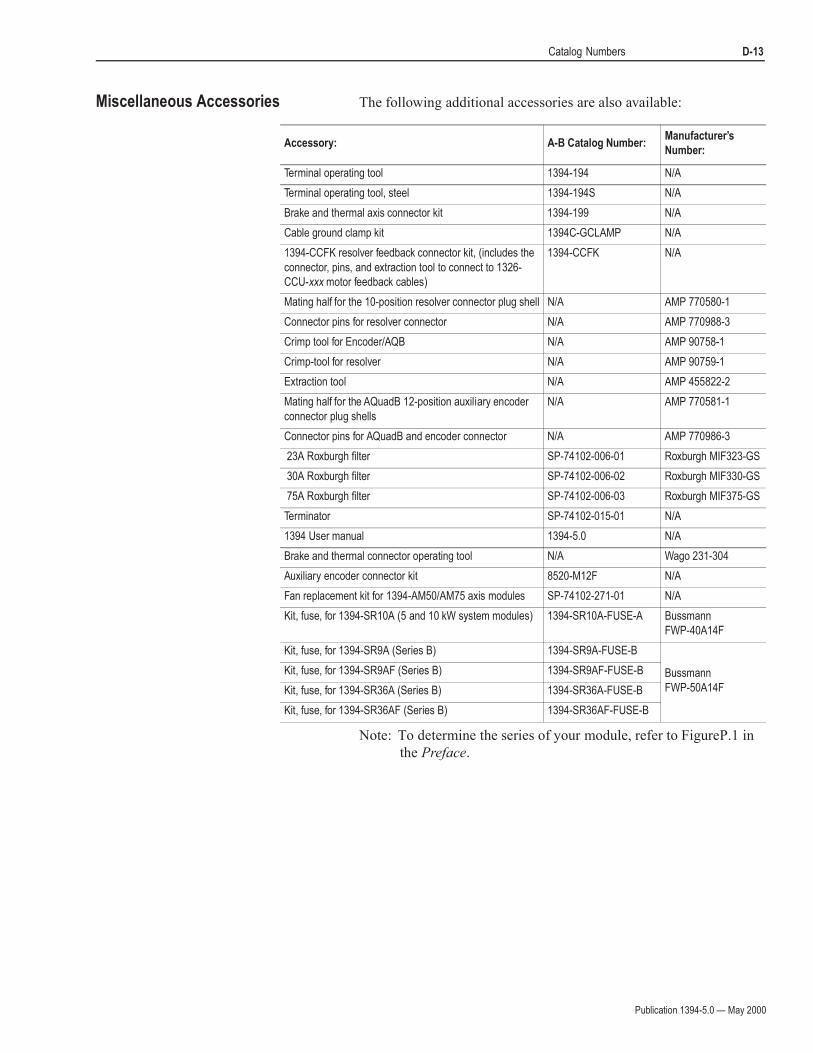
Publication 1394-5.0 — May 2000
Catalog Numbers D-13
Miscellaneous Accessories The following additional accessories are also available:
Note: To determine the series of your module, refer to Figure P.1 in
the Preface.
Accessory: A-B Catalog Number:Manufacturer’s
Number:
Terminal operating tool 1394-194 N/A
Terminal operating tool, steel 1394-194S N/A
Brake and thermal axis connector kit 1394-199 N/A
Cable ground clamp kit 1394C-GCLAMP N/A
1394-CCFK resolver feedback connector kit, (includes the
connector, pins, and extraction tool to connect to 1326-
CCU-xxx motor feedback cables)
1394-CCFK N/A
Mating half for the 10-position resolver connector plug shell N/A AMP 770580-1
Connector pins for resolver connector N/A AMP 770988-3
Crimp tool for Encoder/AQB N/A AMP 90758-1
Crimp-tool for resolver N/A AMP 90759-1
Extraction tool N/A AMP 455822-2
Mating half for the AQuadB 12-position auxiliary encoder
connector plug shells
N/A AMP 770581-1
Connector pins for AQuadB and encoder connector N/A AMP 770986-3
23A Roxburgh filter SP-74102-006-01 Roxburgh MIF323-GS
30A Roxburgh filter SP-74102-006-02 Roxburgh MIF330-GS
75A Roxburgh filter SP-74102-006-03 Roxburgh MIF375-GS
Terminator SP-74102-015-01 N/A
1394 User manual 1394-5.0 N/A
Brake and thermal connector operating tool N/A Wago 231-304
Auxiliary encoder connector kit 8520-M12F N/A
Fan replacement kit for 1394-AM50/AM75 axis modules SP-74102-271-01 N/A
Kit, fuse, for 1394-SR10A (5 and 10 kW system modules) 1394-SR10A-FUSE-A Bussmann
FWP-40A14F
Kit, fuse, for 1394-SR9A (Series B) 1394-SR9A-FUSE-B
Bussmann
FWP-50A14F
Kit, fuse, for 1394-SR9AF (Series B) 1394-SR9AF-FUSE-B
Kit, fuse, for 1394-SR36A (Series B) 1394-SR36A-FUSE-B
Kit, fuse, for 1394-SR36AF (Series B) 1394-SR36AF-FUSE-B