overview of tubular bells - norwep · overview of tubular bells strategies, challenges, and...
TRANSCRIPT
Overview of Tubular Bells Strategies, Challenges, and Technologies
Mike McEvilly
1
February 19, 2015
• Project Overview – Summary
– Unique Aspects of the Project
– Strategies
– Project Schedule
– Drilling/Completions and Subsurface
– SURF
– Hull & Mooring
– Topsides
• Fabrication / Installation / HUC – Summary
– Hull Fabrication
– Topsides Fabrication
– Temporary Workdeck
– Offshore Campaign
– Topsides Lift Plan
• Project Focus Areas / Challenges
• Questions? 2
Agenda
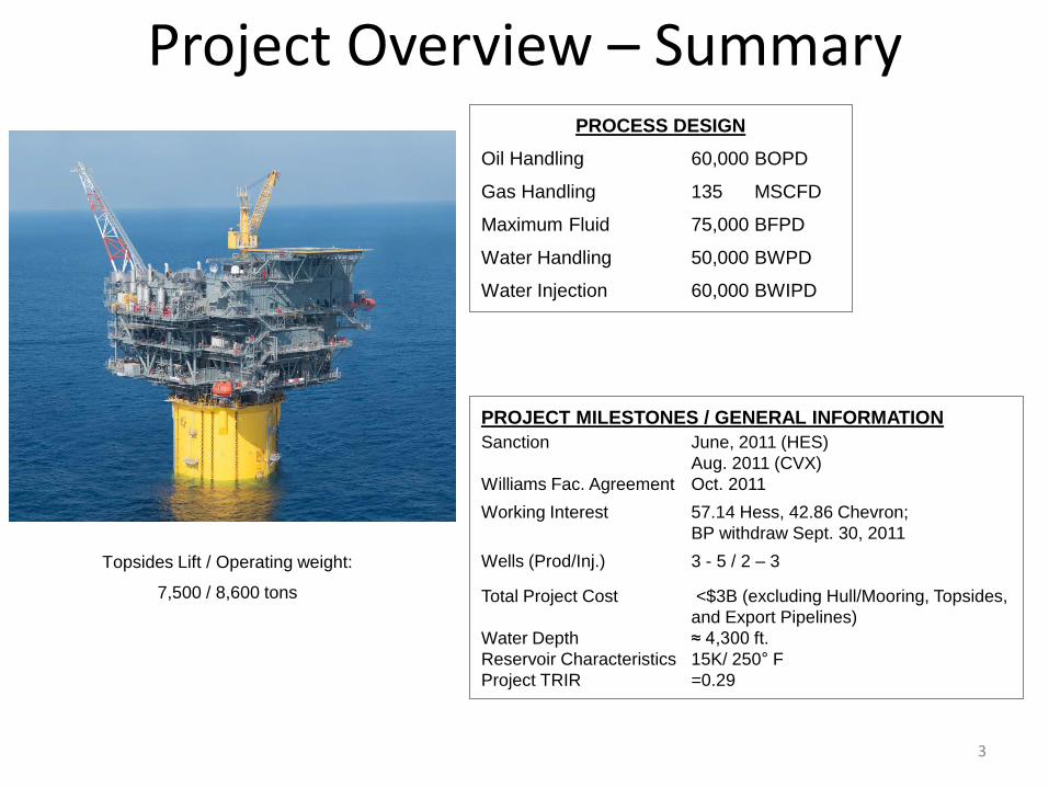
Project Overview – Summary
3
Topsides Lift / Operating weight:
7,500 / 8,600 tons
PROCESS DESIGN
Oil Handling 60,000 BOPD
Gas Handling 135 MSCFD
Maximum Fluid 75,000 BFPD
Water Handling 50,000 BWPD
Water Injection 60,000 BWIPD
PROJECT MILESTONES / GENERAL INFORMATION
Sanction June, 2011 (HES)
Aug. 2011 (CVX)
Williams Fac. Agreement Oct. 2011
Working Interest 57.14 Hess, 42.86 Chevron;
BP withdraw Sept. 30, 2011
Wells (Prod/Inj.) 3 - 5 / 2 – 3
Total Project Cost <$3B (excluding Hull/Mooring, Topsides,
and Export Pipelines)
Water Depth ≈ 4,300 ft.
Reservoir Characteristics 15K/ 250° F
Project TRIR =0.29
Unique Aspects of the Project
• Field first discovered by BP in 2003
• Facility Host provided by Williams (Topsides, Hull/Mooring and Export Pipeline system) • Under-appraised field/ reservoir • First floating production system in the Gulf of Mexico for Hess Corporation, and worldwide in ten
(10) years.
• The engineering and construction of the project was conducted almost entirely within the US
• High Pressure (15K)/ High Temperature (250° F) Reservoir
• 3 Years from Full Sanction to First Oil
4
Strategies
• Due to the perceived economics at the time of sanction, a third-party host was selected as the facilities infrastructure
• The timing of the sanction was driven in part by the imposed “suspension of production” deadline by the government.
• The field was under appraised, therefore the first well (well “B”) would “prove up” the center of the field.
• Seawater injection would be installed to improve overall recovery, and begin within the first year following commencement of production
5
Strategies (Cont.)
• The wells would have the surface casing strings (through the 22”) batch installed to mitigate the risk for swallow water flow. In addition, a “spare” top hole was provided for at each drill center.
• An “ILS” (In-line sled) was installed to accommodate well “C” (Center of the field) if well “B” was successful.
• A subsea production manifold was installed at Drill Center 2 to provide for additional subsea tiebacks.
• An additional production separator was installed and outfitted for future tiebacks.
• The isolation points for the future piping tie-ins for the Gunflint subsea tie-back were addressed prior to installation of the Topsides.
6
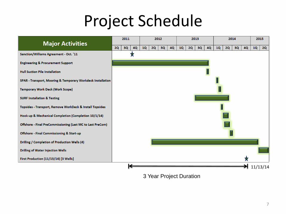
Project Schedule
7
3 Year Project Duration
11/13/14
Drilling/Completions and Subsurface
8
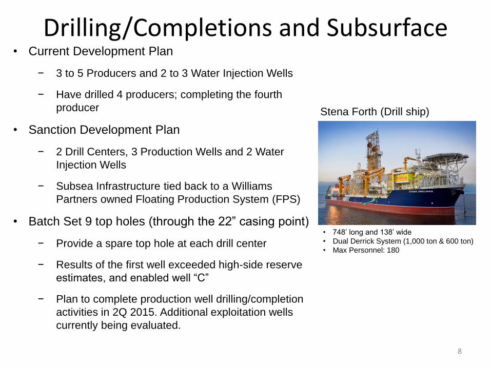
• Current Development Plan
− 3 to 5 Producers and 2 to 3 Water Injection Wells
− Have drilled 4 producers; completing the fourth
producer
• Sanction Development Plan
− 2 Drill Centers, 3 Production Wells and 2 Water
Injection Wells
− Subsea Infrastructure tied back to a Williams
Partners owned Floating Production System (FPS)
• Batch Set 9 top holes (through the 22” casing point)
− Provide a spare top hole at each drill center
− Results of the first well exceeded high-side reserve
estimates, and enabled well “C”
− Plan to complete production well drilling/completion
activities in 2Q 2015. Additional exploitation wells
currently being evaluated.
Stena Forth (Drill ship)
• 748’ long and 138’ wide
• Dual Derrick System (1,000 ton & 600 ton)
• Max Personnel: 180
9
4
2
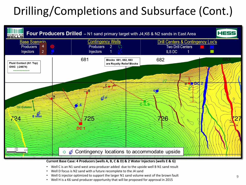
Current Base Case: 4 Producers (wells A, B, C & D) & 2 Water Injectors (wells E & G)
• Well C is an N1 sand west area producer added due to the upside well B N1 sand result • Well D focus is N2 sand with a future recomplete to the J4 sand • Well G injector optimized to support the larger N1 sand volume west of the brown fault • Well H is a K6 sand producer opportunity that will be proposed for approval in 2015
Drilling/Completions and Subsurface (Cont.)
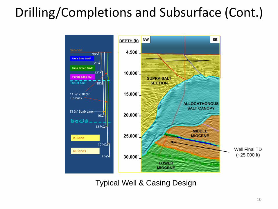
Sea-bed
Top of Salt
Base of Salt
Ursa Blue SWF
Ursa Green SWF
Purple sand HC
36”
28”
22”
16”
18”
7 ¾”
13 ⅝”
10 ⅛”
K Sand
N Sands
13 ⅞” Scab Liner
11 ⅞” x 10 ⅛”
Tie-back
NW SENW SEDEPTH (ft)
4,500’
10,000’
15,000’
20,000’
25,000’
30,000’
SUPRA-SALT
SECTION
ALLOCHTHONOUS
SALT CANOPY
MIDDLE
MIOCENE
LOWER
MIOCENE
Drilling/Completions and Subsurface (Cont.)
10
Typical Well & Casing Design
Well Final TD
(~25,000 ft)
Sea-bed
Top of Salt
Base of Salt
Ursa Blue SWF
Ursa Green SWF
Purple sand HC
36”
28”
22”
16”
18”
7 ¾”
13 ⅝”
10 ⅛”
K Sand
N Sands
13 ⅞” Scab Liner
11 ⅞” x 10 ⅛”
Tie-back
NW SENW SEDEPTH (ft)
4,500’
10,000’
15,000’
20,000’
25,000’
30,000’
SUPRA-SALT
SECTION
ALLOCHTHONOUS
SALT CANOPY
MIDDLE
MIOCENE
LOWER
MIOCENE
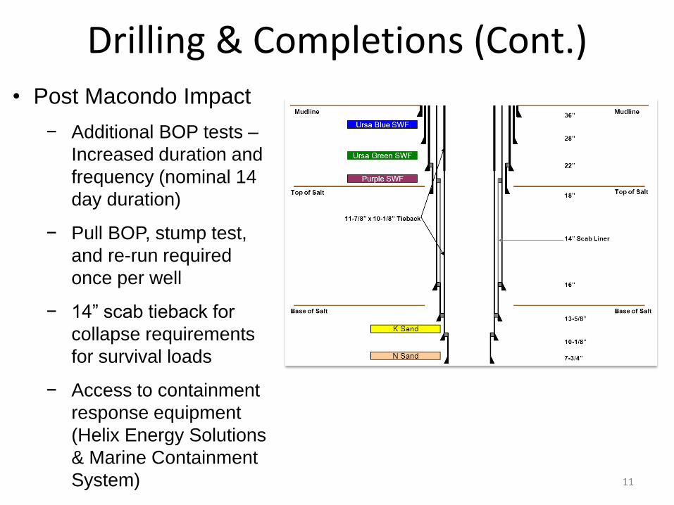
• Post Macondo Impact
− Additional BOP tests –
Increased duration and
frequency (nominal 14
day duration)
− Pull BOP, stump test,
and re-run required
once per well
− 14” scab tieback for
collapse requirements
for survival loads
− Access to containment
response equipment
(Helix Energy Solutions
& Marine Containment
System)
Drilling & Completions (Cont.)
11
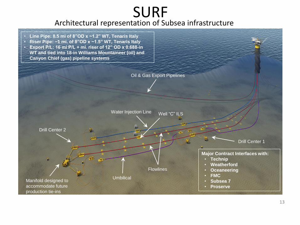
SURF
13
Oil & Gas Export Pipelines
Manifold designed to
accommodate future
production tie-ins
Drill Center 1
Water Injection Line
Drill Center 2
Flowlines
Architectural representation of Subsea infrastructure
• Line Pipe: 8.5 mi of 8”OD x ~1.2” WT, Tenaris Italy
• Riser Pipe: ~1 mi. of 8”OD x ~1.5” WT, Tenaris Italy
• Export P/L: 16 mi P/L + mi. riser of 12” OD x 0.688-in
WT and tied into 18-in Williams Mountaineer (oil) and
Canyon Chief (gas) pipeline systems
Umbilical
Major Contract Interfaces with:
• Technip
• Weatherford
• Oceaneering
• FMC
• Subsea 7
• Proserve
Well “C” ILS
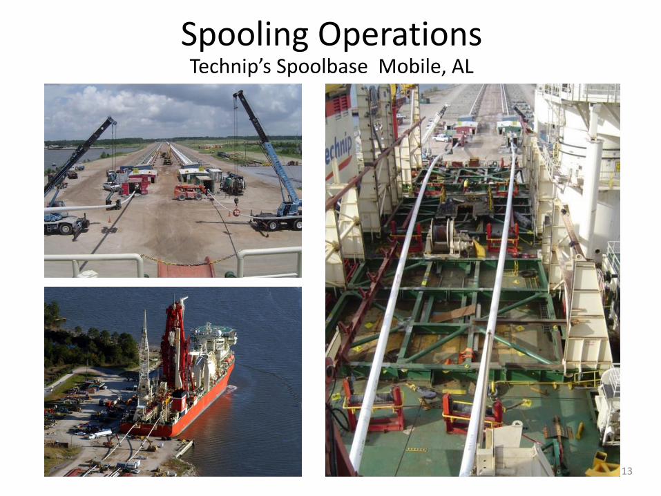
Spooling Operations Technip’s Spoolbase Mobile, AL
13
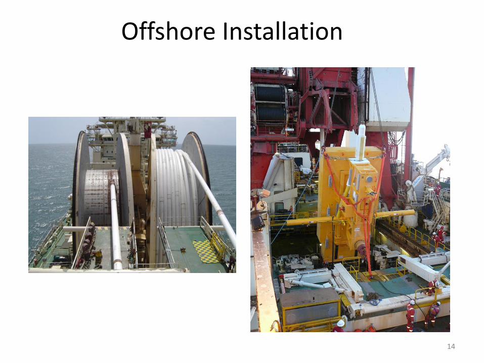
14
Offshore Installation
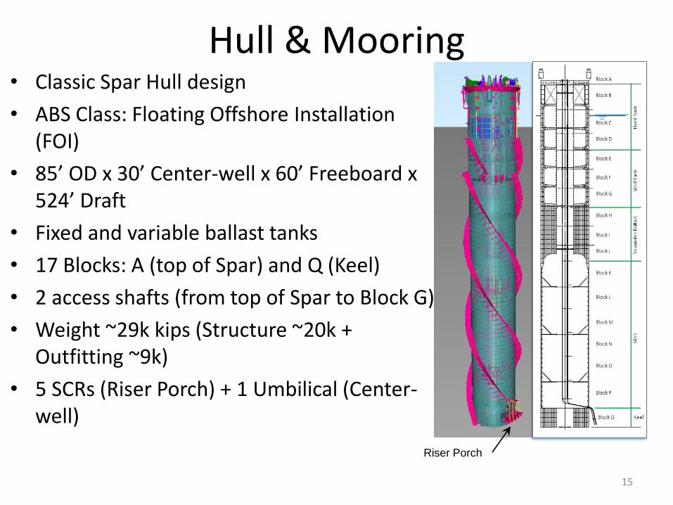
Hull & Mooring • Classic Spar Hull design
• ABS Class: Floating Offshore Installation (FOI)
• 85’ OD x 30’ Center-well x 60’ Freeboard x 524’ Draft
• Fixed and variable ballast tanks
• 17 Blocks: A (top of Spar) and Q (Keel)
• 2 access shafts (from top of Spar to Block G)
• Weight ~29k kips (Structure ~20k + Outfitting ~9k)
• 5 SCRs (Riser Porch) + 1 Umbilical (Center-well)
15
Riser Porch
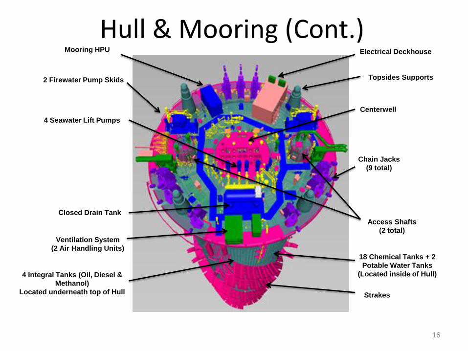
Hull & Mooring (Cont.)
16
Mooring HPU Electrical Deckhouse
Chain Jacks
(9 total)
Topsides Supports
Centerwell
Access Shafts
(2 total)
Strakes
4 Integral Tanks (Oil, Diesel &
Methanol)
Located underneath top of Hull
2 Firewater Pump Skids
Closed Drain Tank
4 Seawater Lift Pumps
Ventilation System
(2 Air Handling Units)
18 Chemical Tanks + 2
Potable Water Tanks
(Located inside of Hull)
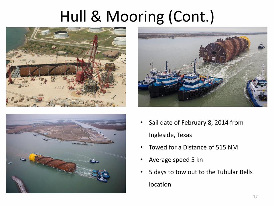
Hull & Mooring (Cont.)
17
• Sail date of February 8, 2014 from
Ingleside, Texas
• Towed for a Distance of 515 NM
• Average speed 5 kn
• 5 days to tow out to the Tubular Bells
location
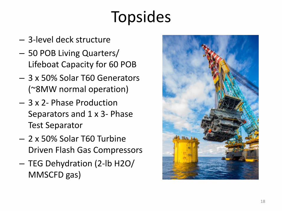
Topsides – 3-level deck structure
– 50 POB Living Quarters/ Lifeboat Capacity for 60 POB
– 3 x 50% Solar T60 Generators (~8MW normal operation)
– 3 x 2- Phase Production Separators and 1 x 3- Phase Test Separator
– 2 x 50% Solar T60 Turbine Driven Flash Gas Compressors
– TEG Dehydration (2-lb H2O/ MMSCFD gas)
18
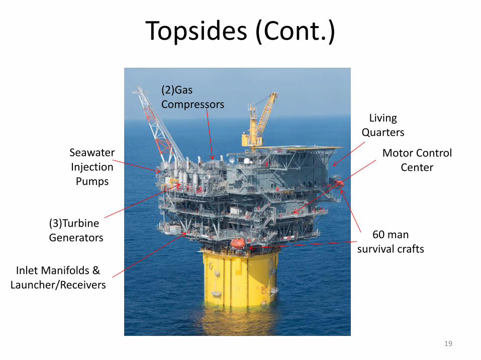
Topsides (Cont.)
19
(2)Gas Compressors
Living Quarters
Motor Control Center
60 man survival crafts
Seawater Injection Pumps
(3)Turbine Generators
Inlet Manifolds & Launcher/Receivers
Fabrication / Installation / HUC
20
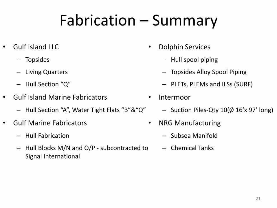
Fabrication – Summary
• Gulf Island LLC
– Topsides
– Living Quarters
– Hull Section “Q”
• Gulf Island Marine Fabricators
– Hull Section “A”, Water Tight Flats “B”&“Q”
• Gulf Marine Fabricators
– Hull Fabrication
– Hull Blocks M/N and O/P - subcontracted to Signal International
21
• Dolphin Services
– Hull spool piping
– Topsides Alloy Spool Piping
– PLETs, PLEMs and ILSs (SURF)
• Intermoor
– Suction Piles-Qty 10(Ø 16’x 97’ long)
• NRG Manufacturing
– Subsea Manifold
– Chemical Tanks
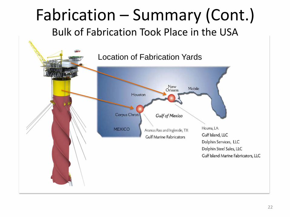
Location of Fabrication Yards
(#) 22
Fabrication – Summary (Cont.) Bulk of Fabrication Took Place in the USA
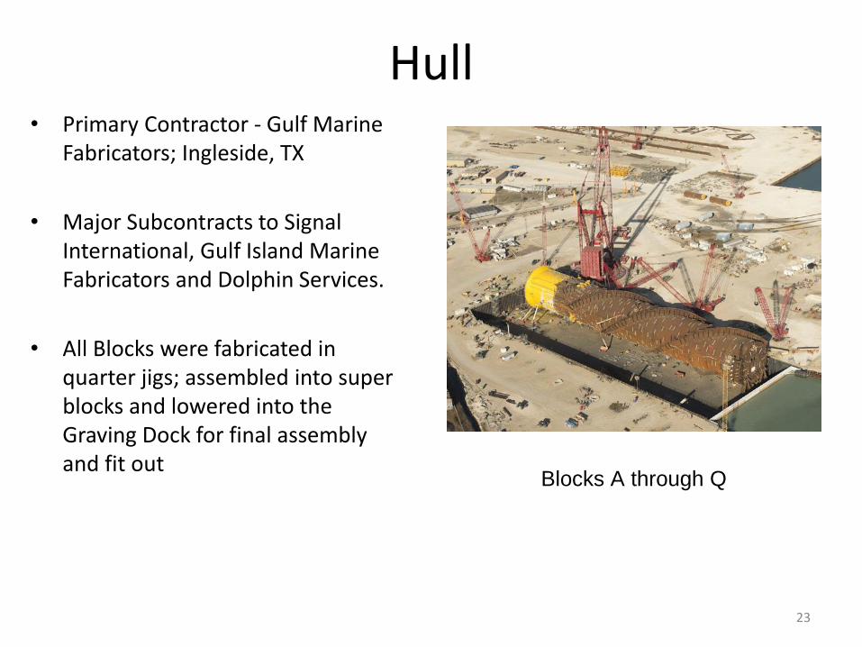
Hull • Primary Contractor - Gulf Marine
Fabricators; Ingleside, TX
• Major Subcontracts to Signal International, Gulf Island Marine Fabricators and Dolphin Services.
• All Blocks were fabricated in quarter jigs; assembled into super blocks and lowered into the Graving Dock for final assembly and fit out
23
Blocks A through Q
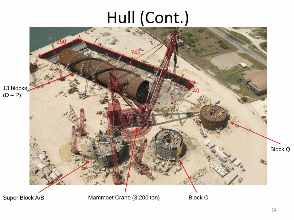
Hull (Cont.)
24
Super Block A/B
250’
745’
40’
Mammoet Crane (3,200 ton)
13 blocks
(D – P)
Block C
Block Q
Hull (Cont.)
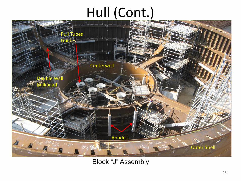
25
Block “J” Assembly
Double Wall Bulkhead
Centerwell
Pull Tubes Guides
Outer Shell
Anodes
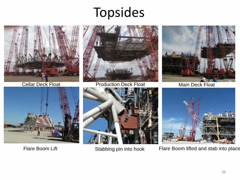
Topsides
26
Stabbing pin into hook Flare Boom lifted and stab into place
Main Deck Float Production Deck Float Cellar Deck Float
Flare Boom Lift
Hanging boom rest for Seatrax crane
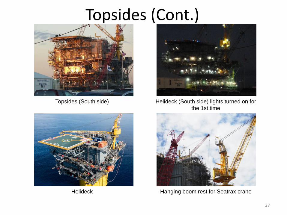
Topsides (Cont.)
Helideck
27
Topsides (South side) Helideck (South side) lights turned on for
the 1st time
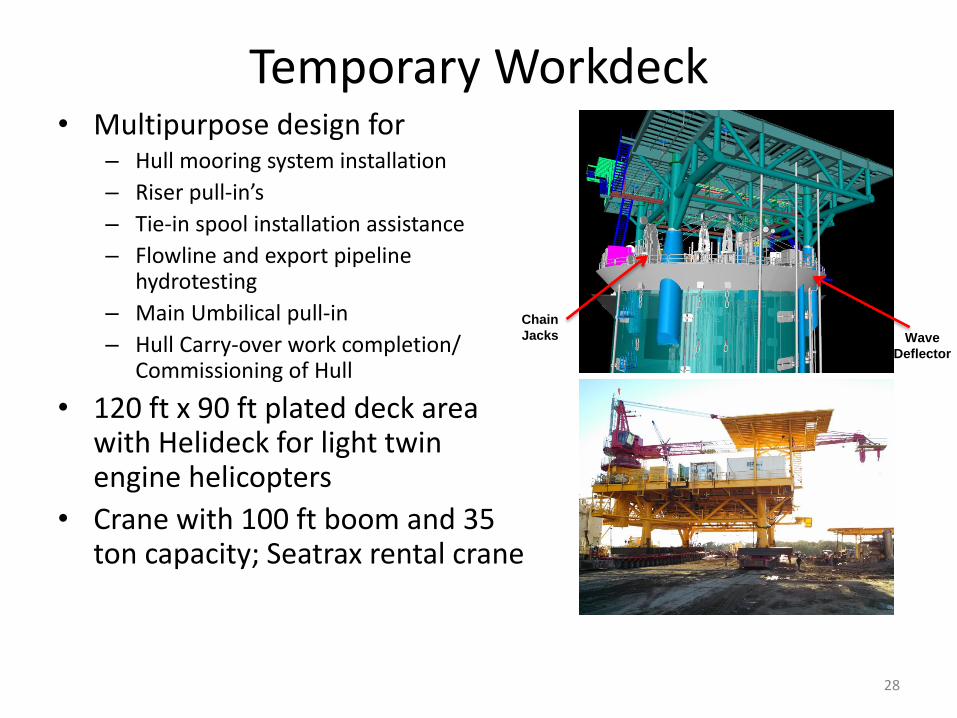
Temporary Workdeck • Multipurpose design for
– Hull mooring system installation
– Riser pull-in’s
– Tie-in spool installation assistance
– Flowline and export pipeline hydrotesting
– Main Umbilical pull-in
– Hull Carry-over work completion/ Commissioning of Hull
• 120 ft x 90 ft plated deck area with Helideck for light twin engine helicopters
• Crane with 100 ft boom and 35 ton capacity; Seatrax rental crane
28
Chain
Jacks Wave
Deflector
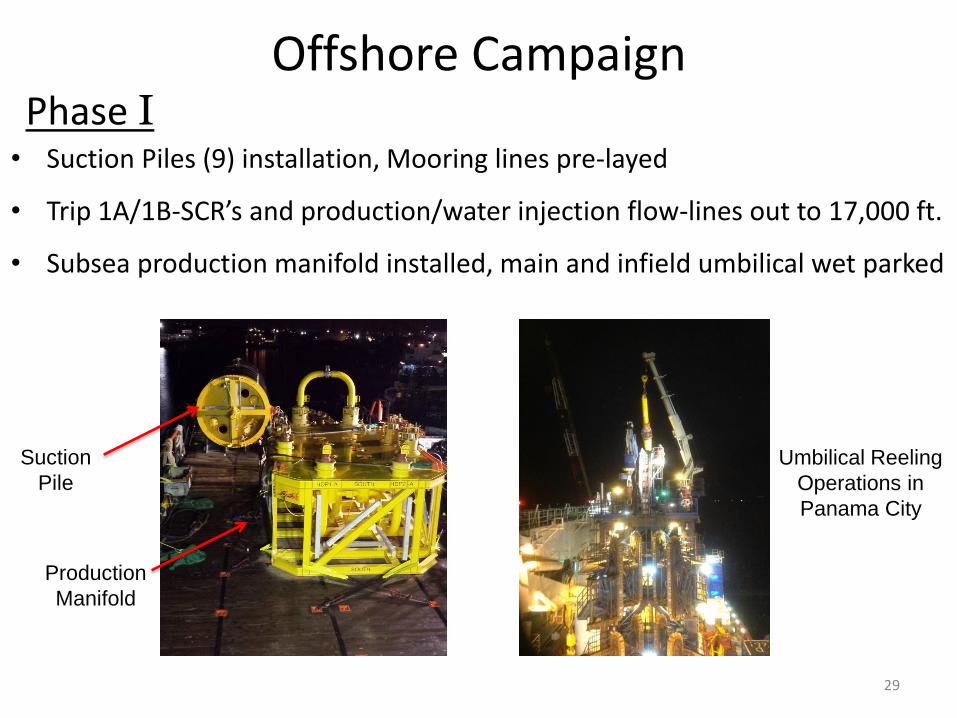
Offshore Campaign
• Suction Piles (9) installation, Mooring lines pre-layed
• Trip 1A/1B-SCR’s and production/water injection flow-lines out to 17,000 ft.
• Subsea production manifold installed, main and infield umbilical wet parked
29
Suction
Pile
Production
Manifold
Umbilical Reeling
Operations in
Panama City
Phase I
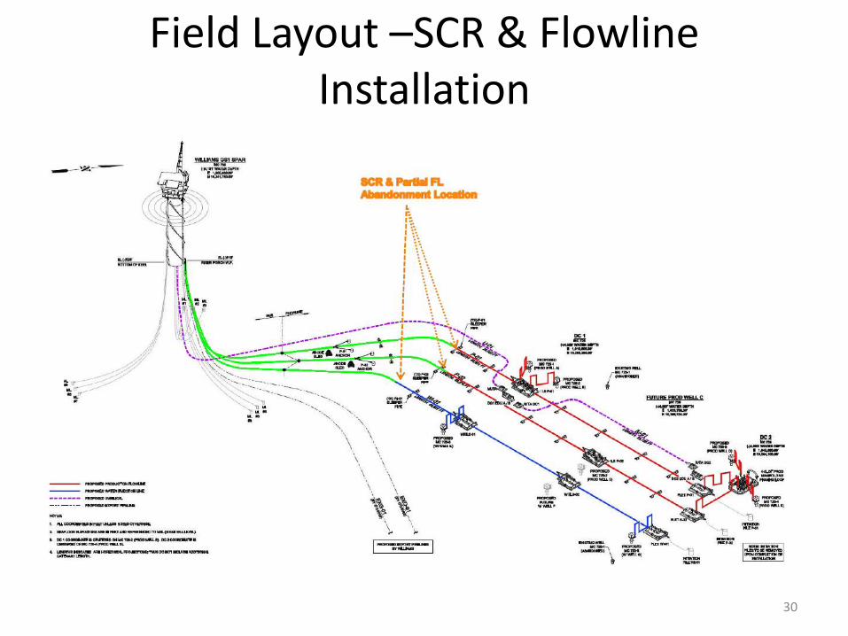
Field Layout –SCR & Flowline Installation
30
Hull UpEnding
31
Phase II
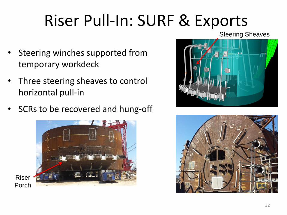
• Steering winches supported from temporary workdeck
• Three steering sheaves to control horizontal pull-in
• SCRs to be recovered and hung-off
32
Riser Pull-In: SURF & Exports Steering Sheaves
Riser
Porch
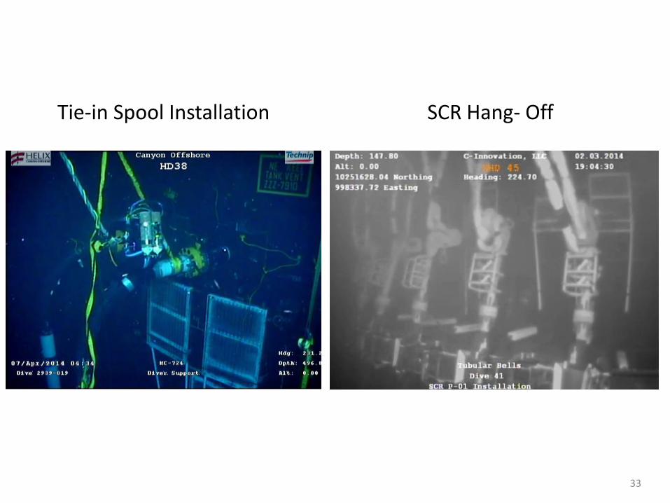
33
Tie-in Spool Installation SCR Hang- Off
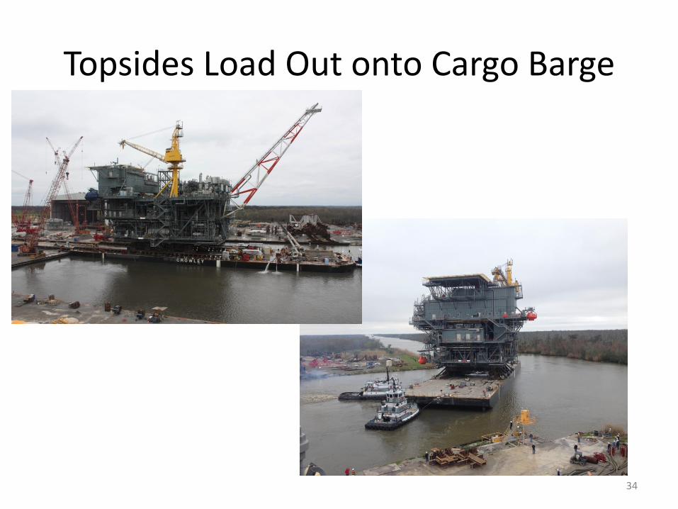
Topsides Load Out onto Cargo Barge
34
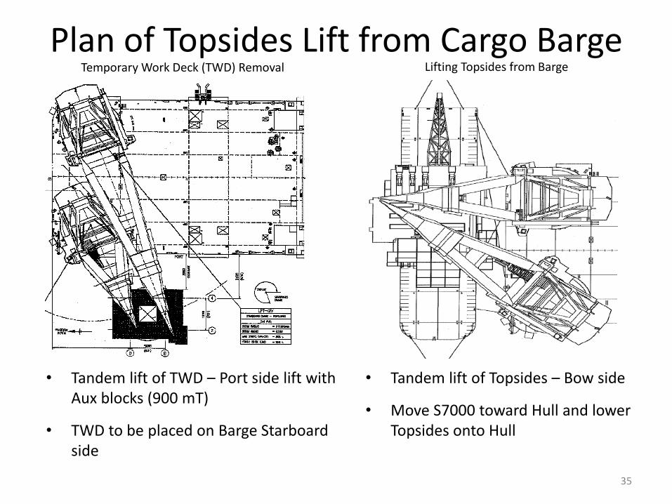
Plan of Topsides Lift from Cargo Barge Temporary Work Deck (TWD) Removal
35
Lifting Topsides from Barge
• Tandem lift of TWD – Port side lift with Aux blocks (900 mT)
• TWD to be placed on Barge Starboard side
• Tandem lift of Topsides – Bow side
• Move S7000 toward Hull and lower Topsides onto Hull
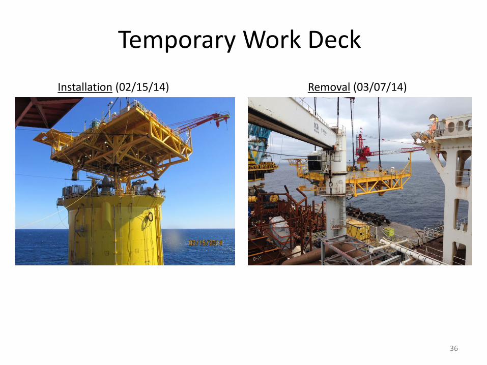
Temporary Work Deck
36
Installation (02/15/14) Removal (03/07/14)
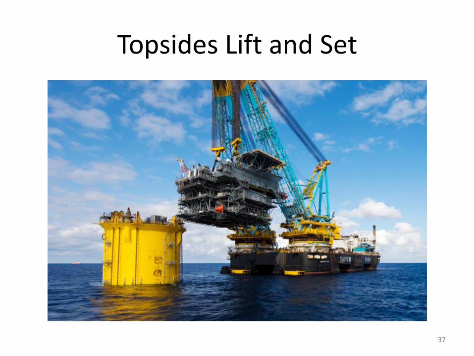
Topsides Lift and Set
37
Project Focus Areas / Challenges • Managing interfaces and ensuring communication across all work groups
– Due to the unique nature of the contract, there are more interfaces than would typically be expected (company-company-regulatory entities, company-contractor and contractor-contractor)
• Relocating the Spar location from MC Block 728 to Block 724
• Ensuring compliance and enhanced reporting requirements in the GOM Post-Macondo era
• SIMOPs; Coordinating multiple vessels during the Offshore Campaign for deferred scopes of work
• Mitigating risk and minimizing the effects of schedule delays (i.e. Hull)
• Accommodating additional work scope in the already aggressive project schedule
– Due to the positive results of the first well, the project incorporated additional design scope to allow for future expansion of the subsea and topsides facilities
– Additional work scope introduced during the hook-up
• Supporting Williams and managing work scope associated with future Gunflint tie-in to minimize impact to production
• Managing and aligning drivers between Hess and Williams
• Assuring an adequate hand-over to operations while building/assembling the necessary operations expertise and experience.
38
39
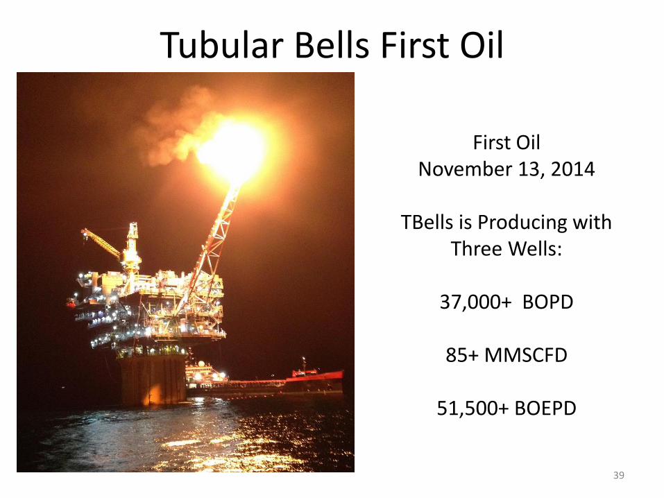
Tubular Bells First Oil
First Oil November 13, 2014
TBells is Producing with
Three Wells:
37,000+ BOPD
85+ MMSCFD
51,500+ BOEPD
QUESTIONS?
40
Contact Information
Presenter: Mike McEvilly
Title: Project Director
Company: Hess
E-mail: [email protected]
Phone Number: (713) 496-6855
41
42
BACK-UP
43
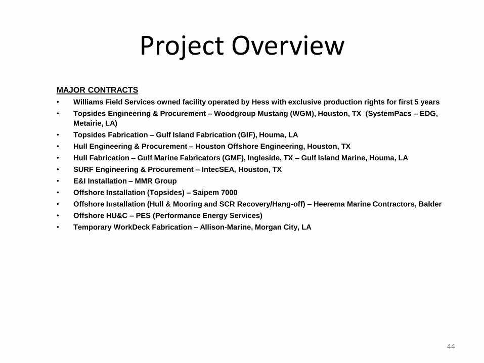
Project Overview
MAJOR CONTRACTS
• Williams Field Services owned facility operated by Hess with exclusive production rights for first 5 years
• Topsides Engineering & Procurement – Woodgroup Mustang (WGM), Houston, TX (SystemPacs – EDG,
Metairie, LA)
• Topsides Fabrication – Gulf Island Fabrication (GIF), Houma, LA
• Hull Engineering & Procurement – Houston Offshore Engineering, Houston, TX
• Hull Fabrication – Gulf Marine Fabricators (GMF), Ingleside, TX – Gulf Island Marine, Houma, LA
• SURF Engineering & Procurement – IntecSEA, Houston, TX
• E&I Installation – MMR Group
• Offshore Installation (Topsides) – Saipem 7000
• Offshore Installation (Hull & Mooring and SCR Recovery/Hang-off) – Heerema Marine Contractors, Balder
• Offshore HU&C – PES (Performance Energy Services)
• Temporary WorkDeck Fabrication – Allison-Marine, Morgan City, LA
44
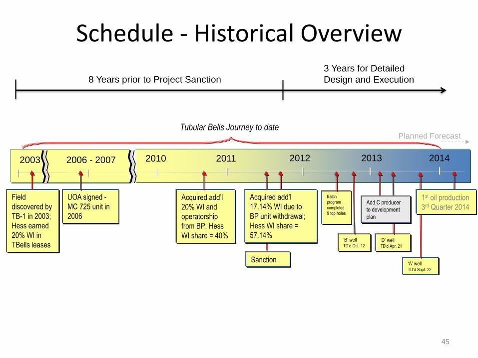
UOA signed -
MC 725 unit in
2006
Acquired add’l
20% WI and
operatorship
from BP; Hess
WI share = 40%
Tubular Bells Journey to date
2010 2011 2012 2013 2014 2003 2006 - 2007
Field
discovered by
TB-1 in 2003;
Hess earned
20% WI in
TBells leases
Planned Forecast
Batch
program
completed
9 top holes
‘B’ well TD’d Oct. 12
Acquired add’l
17.14% WI due to
BP unit withdrawal;
Hess WI share =
57.14%
Sanction
‘D’ well TD’d Apr. 21
Add C producer
to development
plan
‘A’ well TD’d Sept. 22
1st oil production
3rd Quarter 2014
Schedule - Historical Overview
45
8 Years prior to Project Sanction
3 Years for Detailed
Design and Execution
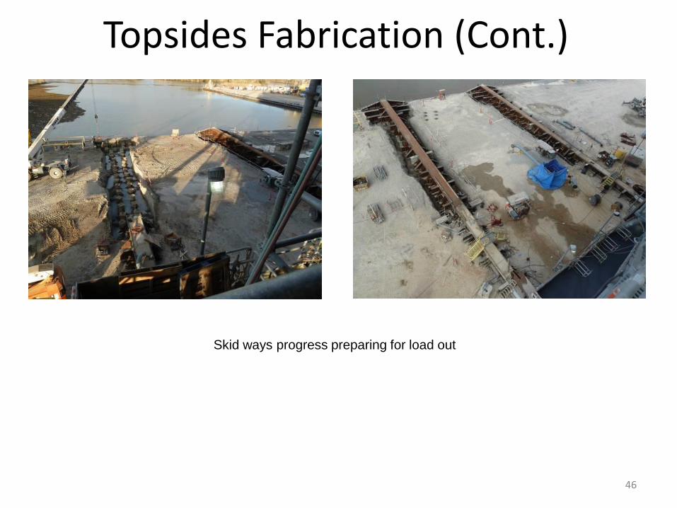
Skid ways progress preparing for load out
Topsides Fabrication (Cont.)
46