overview of the performance of the jet active gas handling ... · 1 abstract the jet active gas...
TRANSCRIPT
JET–P(98)77
R Lässer et al
Overview of the Performance of theJET Active Gas Handling System
during and after DTE1

“This document is intended for publication in the open literature. It is madeavailable on the understanding that it may not be further circulated andextracts may not be published prior to publication of the original, without theconsent of the Publications Officer, JET Joint Undertaking, Abingdon, Oxon,OX14 3EA, UK”.
“Enquiries about Copyright and reproduction should be addressed to thePublications Officer, JET Joint Undertaking, Abingdon, Oxon, OX14 3EA”.

JET–P(98)77
Overview of the Performance of theJET Active Gas Handling System
during and after DTE1
R Lässer, G V Atkins, A C Bell, N Bainbridge, D Brennan,LDörr1, N Green, B Grieveson, J L Hemmerich, G Jones,D Kennedy, S Knipe, J Lupo, J Mart, A Perevezentsev,N Skinner, R Stagg, M Stead, K Wilson, J Yorkshades, .
JET Joint Undertaking, Abingdon, Oxfordshire, OX14 3EA,1FZK Karlsruhe, Postfach 3640, D-76021 Karlsruhe, Germany.
Preprint of a Paper to be submitted for publication inFusion Engineering and Design
February 1999

1
ABSTRACT
The JET Active Gas Handling System (AGHS) was designed, built and commissioned to handle
safely radioactive tritium gas mixtures, to supply tritium (T2) and deuterium (D2) to the JET
torus, to process the exhaust gases with the main purpose to enrich and re-use T2 and D2, to
detritiate tritiated impurities and to keep discharges far below the approved daily release limits.
In addition, the AGHS had to supply the necessary ventilation air streams during maintenance or
repair inside or outside of the AGHS building.
During the first Deuterium-Tritium Experiment (DTE1) at JET in 1997 the AGHS ful-
filled all these tasks in an excellent manner. No unauthorised or unplanned tritium releases
occurred and no operational delays were caused by the AGHS. In fact, this was the first true
demonstration that quantities of tritium in the tens of grams range can be processed and recycled
safely and efficiently in a large fusion device.
At the start of DTE1 20 g of tritium were available on the JET site. About 100 g of tritium
were supplied from the AGHS to the users which necessitated the recycling of tritium at least
five times. Approximately 220 tritium plasma shots were performed during DTE1. Large amounts
of tritium were temporarily trapped in the torus.
This overview presents the performance of the whole AGHS during DTE1 as well as
general aspects such as the preparation for DTE1; the quantities of gases supplied from the
AGHS to the users and pumped back to the AGHS; tritium accountancy; interlock systems;
failure of equipment; and gives detailed information of the gas processing in each subsystem of
the AGHS.
As a consequence of the performance of the AGHS during DTE1 we can state confidently
that the AGHS is ready for further Deuterium-Tritium Experiments.
1. INTRODUCTION
The JET tokamak and the connected gas handling systems were designed and built for the study
of fusion reactor relevant operating conditions including the use of deuterium-tritium gas mix-
tures for plasma fuelling. Therefore, the design had to make provisions for remote maintenance
(due to activation of components) and for the processing of radioactive tritium gas mixtures.
JET has successfully performed two tritium experiments, one at the end of 1991 with 0.2
g on site, designated Preliminary Tritium Experiment (PTE) [1] and one during the months
May/June and September to November 1997 with 20 g on site, designated Deuterium-Tritium
Experiment (DTE1) [2].
Tritium was injected for the first time into a large tokamak during the experiment in 1991,
where the tritium was recovered and stored on uranium beds. In the DTE1 experiment, the
amount of tritium gas injected into the torus was the highest achieved to date on a fusion re-
search facility and the tritium on site was fully processed and recycled several times.
This paper will discuss the processing and the recycling of the tritium at JET.

2
1.1 The Active Gas Handling System (AGHS)
A special plant, designated the JET Active Gas Handling System (AGHS), was constructed to
process and recycle the gases from the torus and Neutral Injectors. The AGHS is located in a
separate building equipped with its own ventilation system and connected with the Torus via
long gas transfer and pumping lines.
The gases collected from the Torus and the other systems are mainly the six hydrogen
molecular types (H2, D2, T2, HD, HT, DT); helium; other gases added to the plasma for tempera-
ture profiles and power control density; impurities such as hydro-carbons (mainly methane),
generated by the interaction of the plasma with the first wall or by the interaction of the atomic
tritium (generated by the tritium decay) with carbon on the surfaces of the primary containment;
and water, nitrogen, oxygen, and argon from leaks.
The main processing steps of the gases in the AGHS are:
1) to pump the gases from the torus and Neutral Injector (NI) systems,
2) to separate impurities from hydrogen isotope mixtures,
3) to recover tritium from tritiated impurities,
4) to isotopically separate hydrogen isotope mixtures into pure T2, D2 and H2, the former two
for recycling to the torus and NI systems and the latter for discharge into environment
5) to store pure deuterium and tritium in uranium beds for further re-use,
6) to re-supply deuterium and tritium to the torus and NI systems.
2. GENERAL DESCRIPTION OF GAS PROCESSING AND RECYCLING IN AC-
TIVE GAS HANDLING SYSTEM (AGHS)
A schematic overview of the various gas streams from the torus and NI systems to AGHS, inside
AGHS and back to the users is shown in Fig. 1.
The gases from the torus and Neutral beam Injection Boxes (NIBs) are pumped via the
torus crown (ML1) and NIB crown (ML2), respectively, by either the Cryogenic Forevacuum
(CF) or Mechanical Forevacuum (MF) systems. Tritium and oxygen in these gases can be moni-
tored by tritium specific detectors and combustible gas monitors. During warm-up of the cryo-
pumps of CF a separation of the pumped gases by distillation into helium, hydrogen and impu-
rities is achieved. Helium and impurities are moved into Impurity Processing (IP) system for
detritiation of tritium containing gas compounds. Hydrogen pumped by CF as well as the hydro-
gen recovered in IP are moved to the Intermediate Storage (IS) system prior to injection into one
of the two hydrogen isotope separation systems: Gas chromatography (GC) and Cryogenic Dis-
tillation (CD). The product tritium and deuterium from the two separation systems are sent to
the Product Storage (PS) system to be supplied to Neutral beam Injection Box at Octant 8 (NIB8)
or to the tritium Gas Introduction Module on the torus (GIM15).

3
MechanicalForevacuum
(MF)
ExhaustDetritiation
(ED)
ImpurityProcessing
(IP)
AnalyticalLaboratory
(AN)
Isotope Separation
Isotope Separation
Gas chroma-tography
(GC)
Cryo-distillation
(CD)
CryogenicForevacuum
(CF)
H2 (D2)
Torus Basement
Torus Hall
Active Gas Handling System (AGHS) JG98.1
64/1
c
Intermediate Storage(IS)
ProductStorage
(PS)
GasIntroduction
box (GI)
D2
D2
D2
D2
D2D2
D2
T2
T2T2
T2
T2
T2
T2
T2
Gas DistributionBox (GD)
TORUS
NIB 8
NIB 4
TRITIUM RECYCLING AT JET
Monitoring
Diagnostics
GIM 15
TDGIS TDGIS
CRYO
CR
YO
CR
YO
PU
MPCR
YO
PU
MP
NIB
Au
xilia
ry v
en
tila
tion
NIB
Cro
wn
Am
ers
ha
m U
—b
ed
To
rus
Cro
wn
ML2ML1
Fig. 1 Schematic flow diagram of torus systems and Active Gas Handling subsystems.
The Analytical Laboratory (AN) is connected via sampling lines to most of the subsys-
tems of the AGHS and is used for characterisation of the various gas compositions in AGHS.
In general, detritiated gases have to pass through the Exhaust Detritiation (ED) for further and
final tritium removal before their discharge into the environment. On the other hand, detritiated
hydrogen from CD can be discharged directly into the environment depending on its final tri-
tium contamination.
All these systems with the exception of ED have their own secondary containments and
some components even tertiary containments. The purpose of the secondary containments at
JET is to capture any permeated or leaked tritium and to transfer the tritium to ED for adsorption
on molecular sieves.
As a further aid to containment the AGH building has dedicated ventilation systems for
normal operation and emergency situations.
2.1 Various Subsystems of the AGHS
This Section gives a short description of each AGH-subsystem by mentioning the main process
and main components. Operational experience on some of the systems is detailed in companion
papers in this volume.
i) Cryogenic Forevacuum (CF) System
Normal pumping of torus systems is done by the CF-system which consists of ten separate cryo-
pumps; large storage and assay volumes (600 and 100 L); and the associated automatic UHV-
valves, pressure gauges, thermocouples, and other instrumentation.

4
All gases except helium are pumped by cryo-condensation at 4 K. To pump helium, four
of the cryo-pumps are equipped with activated charcoal sorption panels.
Controlled warm-up of a cryo-pump allows the separation of the pumped gases into three
streams of helium, hydrogen and impurities.
ii) Impurity Processing (IP) System
Helium and impurities are sent to the IP-system where residual amounts of tritiated gas species
are cracked on hot uranium (U) beds or burnt to water by the addition of small batches of oxygen
in the presence of a platinum de-oxo catalyst.
Hydrogen and tritium are recovered by cracking water on hot U-beds. The residual gas left
contains mainly helium, CO and CO2 and can be discharged via the Exhaust Detritiation (ED)
system (see below).
The main components of IP are: one 2 m3 mixing tank; two Normetex pumps (150 m3/h);
one recombiner; one cold trap; four JET uranium beds; and two iron beds.
The operational experience with this system is detailed in [3] in a companion paper.
iii) Intermediate Storage (IS) System
The hydrogen from CF and IP is sent to the Intermediate Storage system for temporary storage
prior to injection into one of two isotope separation systems.
IS contains four JET U-beds which are located in an evacuated secondary containment.
JET uranium beds can contain up to 4.284 kg of uranium and can store up to 27 moles (605 NL)
of hydrogen if loaded fully, but normally they are filled only to two thirds of their total hydrogen
capacity.
iv) Cryogenic Distillation (CD) System
Hydrogen from IS can be sent via two feed lines to the CD system. Three product lines exist
where the products (protium, deuterium, tritium) can be withdrawn with very high purity if the
CD system is operated correctly and the tritium amount is near to its optimum inventory of
approximately 33 g. For the product protium (H2) the contamination level of tritium is below 1
ppm which makes direct discharge into the environment possible. The deuterium and tritium
products are sent to the Product Storage (PS) system.
The main components are three packed distillation columns; expansion volumes; siphon
pumps; and associated flow and pressure transducers.
The operational experience with this system is described in detail in [4] elsewhere in this
volume.
v) Gas Chromatographic (GC) System
Displacement gas chromatography is used to enrich tritium and deuterium from the six hydro-
gen molecules. The packing material used is palladium (Pd).

5
Displacement gas chromatography is a batch process. At the end of every separation run
the hydrogen molecule (H2) with the highest affinity to Pd has to be desorbed. This is done by
heating the columns to about 200 C. The deuterium and tritium products are sent to the Product
Storage (PS) system.
The operational experience with this system is detailed in [5] in a companion paper.
vi) Product Storage (PS) System
The isotopically pure gas products of CD or GC are collected and stored in U-beds of the PS-D2
and PS-T2 systems. The PS-T2 U-beds contain only about 1 kg of uranium per bed. In the case of
the PS-T2 U-beds, in situ determination of the tritium inventory can be performed by quasi-
adiabatic calorimetry. In addition, the gas content of the U-beds can be determined by gas
desorption into 100 L or 700 L reservoirs and (PVT-c) measurements.
Metal getter beds are a safe storage technique for tritium. In addition, in U-beds the decay
helium stays trapped in the uranium. Temperature cycling of the uranium and removal of the
helium in the gas phase produces tritium with a very low helium-3 concentration, an important
consideration when supplying a neutral beam injector [6].
A disadvantage of uranium getter beds is that inert gases which are not absorbed by the
getter material can lead to blanketing effects. The absorption of hydrogen by the uranium slows
down because the hydrogen has to diffuse through ‘inert’ gas layers surrounding the getter ma-
terial. A simple remedy against blanketing is to circulate the gas through the U-beds by means of
a pump; Normetex and metal bellows pumps are installed for that purpose in the PS-system.
vii) Gas Introduction (GI) System and Gas Distribution (GD) System
Deuterium and tritium are supplied from the PS-D2 and PS-T2 systems via GI and GD to the
users: for Neutral Beam Injection via Octant 8 (NIB8) and for gas puffing directly into the torus
via the Gas Introduction Module 15 (GIM15).
The long transfer lines are surrounded by secondary containments in the same way as the
other systems of the AGHS.
The accountancy of the gases supplied to the various users is mainly done in the GI-
system via (PVT-c) measurements.
The Gas Introduction system for the NIB8 neutral beams is described in more detail in a
companion paper [6] in this volume.
viii) Mechanical Forevacuum (MF) System
The MF-system has the following roles: to pump the Torus and NIB-cryo-pumps from atmos-
phere; to pump the Torus and the NIB cryo-pumps during normal operation when CF is not
available; to supply the necessary backing pressure for the Torus turbo-pumps during helium
glow discharge; and to discharge gases from the various AGH-subsystems via the Exhaust
Detritiation (ED) system.

6
The following pumps are installed in MF: one 600 m3/h Normetex pump; two 150 m3/h
Normetex pumps; and one 1000 m3/h roots pump.
ix) Exhaust Detritiation (ED) System
Almost all gases (except the protium product of the CD-system and the exhaust gases of the
analytical gas chromatograph) are sent through the ED-system prior to their discharge. Also in
case of emergency (e.g. after a window rupture on the Torus or after a tritium leak into one of the
rooms on the active side of the J-25 building) the air from the Torus or from the rooms would be
pumped into the ED-system and detritiated.
The ED-system is a conventional tritium removal system where tritium and tritiated gas
species are burnt to water. The water is trapped on dry molecular sieve. Wet molecular sieve
beds are regenerated by heating, the desorbed humidity is collected in coolers and finally stored
in drums if the tritium concentration is high.
The system is designed to reduce the incoming tritium concentration by more than a factor
of 1000.
x) Analytical Laboratory (AN)
The AN is connected via small bore pipework with most other subsystems of the AGHS. In this
way samples from other subsystems can be analysed by the three analytical techniques available
in AN: analytical gas chromatography; mass spectroscopy (Omegatron and quadrupole); and
ionisation chambers. In addition, the CD-product streams protium and deuterium are analysed
by sensitive katharometers.
The analytical tool most often used is the gas chromatograph: six detectors are available to
study the composition and tritium concentrations in the gas mixtures as follows: one thermal
conductivity detector (TCD); one flame ionisation detector (FID); two ionisation chambers (IC);
and two flow proportional counter detectors (FPCD).
The operational experience with the AN is described in detail elsewhere [7] in this vol-
ume.
xi) Over/Under Pressure Protection System (O/UPPS)
All process lines of the active gas handling system where tritium process gas is handled at
higher pressures are surrounded by secondary containments. These containments are either evacu-
ated or filled with nitrogen or argon and kept a few mbars below atmospheric pressure, and are
intended to retain the tritium in case of a primary containment failure.
3. OPERATIONS AND STAFF TRAINING ON THE AGHS
3.1 Operations
During DTE1 the AGHS was permanently manned by four four-man shift teams which worked
to a 12 hour shift pattern. Each shift team consisted of an Operation Engineer, Plant Supervisor,

7
Control Technician and Analytical Technician. At all times two shift team members who were
on rest days remained ‘on call’ to cover any short term absences during the operations period.
3.2 Training
An extensive training programme was carried out prior to DTE1 in order to ensure that members
of the AGH-group were sufficiently experienced to operate the plant safely and also that the
members of the groups interfacing with the AGHS operations were familiar with the operating
procedures that would be followed. This training programme complemented the practical expe-
rience of operating the AGHS during Trace and Full tritium commissioning.
3.2.1 Training of the AGH Group staff
A training grid was devised depicting the various topics which needed to be known for each of
the four operational roles in the AGHS against the individuals within the group. Staff were then
trained by practical demonstration and/or lecture. At the end of the training period a review
panel met to consider the level of training and achievement of each member of the group. Staff
were then officially appointed to one or more of the four roles in the AGHS organisation.
3.2.2 Training of external personnel
A two day course was devised to familiarise members of other groups at JET. The course con-
sisted of an overview of the AGHS followed by a plant tour and then a detailed description of the
various subsystems within the AGHS. The courses were tailored to suit the group being lectured
e.g.: highlighting the Gas introduction system for the Neutral Beam Operations group.
In return these external interface groups provided lectures on their systems and operating
procedures for the members of the AGHG.
3.2.3 Practical Training
Prior to DTE1 the AGHS supported the machine operations for several months as described
below. During this period the shift teams gained practical experience of many of the operations
which would be carried out during DTE1 but using deuterium only. It also enabled the interface
procedures for gas feed and recovery to be tested.
At the end of the training period four shift teams of four men each were sufficiently trained
to safely operate the AGHS.
4. COMMISSIONING OF THE AGHS
The commissioning of the AGH-plant was performed in five phases:
- Inactive commissioning;
- Trace tritium commissioning;
- Full tritium commissioning;
- Inactive commissioning of Interface systems; and
- Final preparations for DTE1 (expanding the tritium boundary).

8
4.1 Inactive commissioning
The performance of the subsystems of the AGHS was tested with inactive gases, the functioning
of tritium specific equipment being tested with gamma sources wherever possible. Leak tight-
ness of the systems was tested with helium leak detectors. Subsystems of the AGHS passed
these tests only when their total leak rate did not indicate any leak in the 10-9 Pa.m3.s-1 range.
During this phase AGHS was used occasionally to pump the torus to test the performance of the
MF and of the CF systems. Results of the inactive commissioning are discussed in the ‘Inactive
commissioning report’ and in various publications [8] - [14].
4.2 Trace tritium commissioning
Trace tritium commissioning was performed with the tritium gas used during the PTE-experi-
ment and stored in U-beds located in the JET U-bed safe store. The total tritium amount was
about 30 TBq (800 Ci or 0.08 g) in 166kPa.m3 of hydrogen. All AGH-subsystems were trace
tritium commissioned with the exception of the systems interfacing with the torus such as MF,
CF, GI and GD. This was done to prevent accidental tritium introduction into the torus. These
systems functioned as a buffer between AGHS and torus systems. In addition, no trace tritium
gas was directly injected into the Exhaust Detritiation (ED) system. The first tritium tests were
done with gas treated in Impurity Processing (IP) system and injected into ED with the purpose
of further detritiation. The performance of ED was monitored and checked during those injec-
tions.
At the end of trace tritium commissioning three objectives were completed: a) the systems
were leak tested with trace tritium gas; b) tritium sensitive detectors were exposed to trace
tritium gas and their expected response confirmed; and c) the trace tritium gas was processed in
the Cryogenic Distillation (CD) system, tritium was enriched and most of the total gas amount
was discharged to the stack.
Results of trace tritium commissioning have been published elsewhere [15].
4.3 Full tritium commissioning
Full tritium commissioning was performed with about 3 g of tritium supplied through the Cana-
dian Fusion Fuels Technology Project (CFFTP) in an Amersham U-bed (containing 320 g of
uranium). With approximately 1 g tritium the GC system for isotope separation was tested and
very good product purity obtained. Altogether, the AN, PS, IS and GC systems were tested with
pure tritium and results of full tritium commissioning have been reported previously [16].
4.4 Inactive commissioning of the interface systems
Before the start of the DTE1 phase the GI and GD systems were tested with deuterium. In the
same way the CF system was tested for weeks during normal operation of the torus to assure that
the CF system could handle the various gas loads from regenerations of the cryopumps of the
NIBs and Pump Divertor (PD).

9
4.5 Final Preparations for DTE1: expanding the tritium boundary.
The systems GI, GD, and CF were tritium commissioned very shortly before the commence-
ment of DTE1. First the tritium boundary was expanded into these systems and they were tri-
tium leak tested with a 1% tritium-99% deuterium mixture. After no leaks were detected, GI and
GD were tested with pure tritium. Again no leaks were found which clearly demonstrated that
the inactive commissioning had been done very carefully. CF was not tested with pure tritium
because only subatmospheric pressures were achievable with the available tritium amount due
to the very large volumes in CF.
All torus and NI operations for DTE1 were carried out in accordance with approved Oper-
ating Instructions (OIs). These procedures were checked in the final preparation phase for DTE1.
5. SUPPLY OF DEUTERIUM & TRITIUM TO TORUS AND NEUTRAL INJECTOR
SYSTEMS DURING AND AFTER DTE1
The DTE1 phase started officially with the supply of 1% tritium-99% deuterium mixture to the
Neutral Beam Injectors.
Tritium and/or deuterium were supplied to the users in weeks 21 to 47 of 1997 excluding
weeks 25 to 36 due to the intervention to cure a small leak on the NIB8 system [17] and the
subsequent restart.
Prior to DTE1 the tritium gas amount on site was increased from the 3 g, used for the full
tritium commissioning program, to 20 g. The 17 g were supplied by CFFTP in four Amersham
U-beds.
After arrival at JET the tritium content of these U-beds was measured by precision
calorimetry [18]. The determined tritium content was compared with the value stated by the
supplier. In all cases the agreement between these values was better than 0.3%.
5.1 Tritium purity supplied to JET
Table 1 gives the results of analytical gas chromatography performed in Chalk River National
Laboratory (CRNL) and at JET in atomic ratio. The results are in good agreement, the main
difference occurs for D. An explanation for this difference is that the Amersham U-bed supplied
by JET for transport and the JET PS-T2 U-beds
had all been activated with deuterium. A small
amount of deuterium is not removable from the
uranium even after extensive heating and
pumping. This deuterium can lead to dilution
of the tritium. The tritium sample at JET was
determined after absorption of the tritium on a
PS-T2 U-bed.
SISYLANALNRC SISYLANATEJ
%nioitarcimotA %nioitarcimotA
H63.0 H22.0
D551.0 D14.0
T584.99 T73.99
Table 1: Purity of the tritium gas measured at CRNL andat JET
10
5.2 Transfer of tritium from Amersham U-beds to PS-T2
The Amersham U-beds were connected to the pipework of the Tritium-Make-up Box in the
analytical laboratory. After leak tests of the new connection, the Amersham U-beds were heated
to approximately 500°C and the desorbed tritium was moved to one of the four U-beds of the
Tritium Product Storage System. During the transfer the tritium amount was again determined
via (PVT-c) measurements using well calibrated volumes and high accuracy pressure gauges.
The concentration c was obtained from the analytical gas chromatographic (AN-GC) system
after absorption on a PS-T2 U-bed. For very pure tritium gases two fully independent analytical
techniques of the AN-GC are employed: thermal conductivity detector and ionisation chamber
[7]. The results of both techniques showed very good agreement.
During the transfer of the tritium from the Amersham U-bed to PS very high tritium con-
centrations were observed in the N2 atmosphere of the Make-up Box due to permeation of tri-
tium through the hot walls of the U-bed. These commercially available Amersham U-beds have
no secondary containment to capture permeated tritium. Amersham U-beds are used because
they are part of a licensed transfer package for tritium. The tritium contamination levels in the
Make-up Box due to the transfer were by far the highest values (approximately 1000 DAC in the
Tritium Make-up Box) seen until now in any of the AGHS containment boxes.
After transfer the Amersham U-beds were disconnected from the pipework inside the
Make-up Box and re-examined by precision calorimetry. Small residual levels of tritium (‘heels’)
were observed in the uranium. The heels were negligible ( approximately 0.1 - 0.2%) compared
to the tritium inventory supplied. Because the same procedure for the transfer of tritium from the
Amersham U-beds to the AGHS was followed, the heels left in individual Amersham U-beds
were very similar.
The two methods used - precision calorimetry and (PVT-c) measurements - gave a very
accurate total tritium gas amount in the AGHS. The relative agreement was better than 0.5%.
The tritium amount available at the 15 May 1997 12:00, just before the start of DTE1, was
20.448 g or 8260Pa.m3 at 20°C.
The Amersham beds with their small tritium heels (0.033 g) are stored in the JET U-bed Safe
Store.
5.3 Production and use of a 1% tritium-99% deuterium mixture
A gas mixture of approximately 2 104Pa.m3 of 1% tritium-99% deuterium was produced by
mixing appropriate gas amounts of very pure tritium and deuterium. The actual atomic compo-
sition of the gas mixture achieved was 0.12% H, 98.96% D and 0.92% T.
This gas was used
a) in the expansion of the tritium boundary to leak test the GI, GD, the NIB8 Tritium-Deute-
rium Gas Introduction System (TDGIS) [6], the NIB-crown (ML2) and CF.

11
b) to supply the users with a 1% tritium-99% deuterium gas mixture for various plasma
experiments.
After the performance of the 1% tritium-99% deuterium plasma shots the residual gas
mixture was separated again into pure tritium and deuterium using the preparative GC-system.
5.4 Supply of deuterium and tritium from Product Storage to the Neutral Injector and
Torus systems
Figure 2 shows in a schematic diagram
the supply of deuterium and tritium
from PS via GI to the users NIB8 and
GIM15. During DTE1 only the three
lines shown in Fig. 2 were used for D2
and T2 supply, but in reality ten trans-
fer lines are installed which allow the
connection with Neutral Injector Box
at Octant 4 (NIB4 -shown in Fig. 1 by
dashed lines), Pellet Injection system
and other gas introduction modules.
These are foreseen for use in future
Deuterium-Tritium Experiment at JET
(DTE2) [19].
Pure deuterium and/or tritium gas
was supplied to GI by heating U-beds
of PS-D2 and/or PS-T2 to about 450 °C.
In GI the gas amount was determined
in well calibrated volumes, its pressure
measured with highly accurate capaci-
tance manometers and the temperature
measured with PT-100 precision resis -
AN AN
NIB8
~100m
D2 T2
D2
T2
D2or T2
GC/CD GC/CD
UB–1
UB–2
UB–3
UB–4
700L
UB–5
UB–6
UB–7
UB–8
100L
5L 5L
GIM15
PS
PS–T2PS–D2
GI
JG97
.416
/7c
D2 T2
Fig. 2 Schematic flow diagram for deuterium and tritium supplyfrom Product Storage (PS) system via Gas Introduction (GI) andGas Distribution (GD) to the users: Neutral beam injection Box(NIB)8 and Gas Introduction Module (GIM)15.
tors. The valves above the 5L volumes in Fig. 2 have to be enabled by keys before they can be
operated via the automatic control system. In this way the users have full control over these
valves. With the key removed no compressed air is applied to the actuators of the valve and
opening is not possible either by malfunction of the control system or by operator error.
From GI the D2 and T2 gases were supplied via long transfer lines (>100 m) to the Gas
Distribution (GD) Box and from there to the users: NIB8 TDGIS and GIM15.
At the end of a day’s operation the gas amounts left in the pipework of GI and GD were
determined again and pumped back to the U-beds of PS. The difference of the two measure-
ments gives the total amount of gases supplied to the users. A large effort was made to establish

12
the tritium gas amounts supplied to the users accurately. These values are listed for tritium and
deuterium in the Table 2 and 3 as a function of week numbers in 1997.
Table 2: Quantities of pure tritium supplied to NIB8 and GIM15
EMIT7991raeY
Terup 2 8BINotm.aPk( 3 )C°02ta
Terup 2 51MIGotm.aPk( 3 )C°02ta
12keew 5602.1 1300.0
22keew 4693.3 9910.0
32keew —— 9332.2
42keew —— 7003.2
63ot52keew tratserdnanoitnevretni8BIN
73keew —— 20.0
83keew 8537.2 978.0
93keew 1892.2 8165.0
04keew 3558.3 1436.1
14keew 0135.2 1199.1
24keew 3200.2 6468.0
34keew 7155.2 9894.0
44keew 4684.2 2217.0
54keew 0708.1 5045.1
64keew 4364.1 5323.1
74keew —— 6600.0
94ot84keew semmargorplatnemirepxe1ETDtsopotnruterdnapu-naelCsuroT
05keew —— 5300.0
∑ 3033.62= ∑ 3208.31=
∑ 6231.04=
Table 3: Deuterium amounts supplied to NIB8 and GIM15
EMIT7991raeY
D2 8BINotm.aPk( 3 )C°02ta
EMIT7991raeY
D2 51MIGotm.aPk( 3 )C°02ta
64-12keeW 69 94-12keeW 5.8
13
Deuterium and tritium are stored in uranium beds (UB) 1 to 8 of PS. The PS system can be
divided into three sections. Only two are shown in Fig. 2.
a) PS-D2: The product storage system for deuterium contains four U-beds with 4.282 kg of
uranium each and a 700 L reservoir. PS-D2 has interconnecting lines to GC, CD, AN and
GI and connections to PS-T2 and the pumps of PS (not shown in Fig. 2).
b) PS-T2: The product storage system for tritium contains four U-beds with 1.19 kg uranium
each and a 100 L reservoir. The design and dimensions of the PS-D2 and PS-T2 U-beds are
identical. The only difference between them is that the PS-T2 U-beds contain about a
quarter of the uranium of the PS-D2 U-beds. Due to the limited amount of tritium expected
to be handled during DTE1 the uranium amount for PS-T2 beds was reduced. This also
minimises the heel of tritium in a U-bed and makes a larger part of the tritium on site
available for re-use. PS-T2 has interconnecting lines to GC, CD, AN and GI and connec-
tions to PS-D2 and the pumps of PS (not shown in Fig. 2).
The third section of PS not presented in Fig. 2 contains combinations of pumps with the
main purposes to achieve good vacuum conditions in primary, secondary and tertiary contain-
ments and to circulate gases through U-beds or tanks with the purpose of removing blanketing
gas. The Pumps are: turbo-molecular pump; getter pump using SAES-707 material; sputter pump
with Fe instead of Ti to achieve selective pumping for inert gases but not for hydrogen; Normetex
pump; and metal bellows pump.
During the DTE1 phase tritium and deuterium were supplied to NIB8 and GIM15. NIB4
and all other gas introduction modules used their own gas supplies. Table 2 gives the amounts of
pure tritium supplied to NIB8 and GIM15 as a function of weeks.
According to Table 2 more than 99 g of tritium were supplied to the users. This means that
the total tritium gas amount available at JET was recycled to the torus at least four times. If one
also considers that a large fraction of up to 11.5 g of tritium supplied to the torus was temporarily
trapped there [20], the tritium available and handled in the AGHS was recycled at least five
times.
The AGHS system was specially built for this reprocessing purpose and is the first tritium
handling facility in connection with a fusion research machine used for recycling large amounts
of tritium.
Table 3 shows the gas amounts of deuterium supplied to NIB8 and GIM15 during DTE1
and up to week 49. After week 46 the D2 gas supply to NIB8 and GIM15 from the AGHS was
stopped. NIB8 was reconnected to its own gas supply independent of AGHS.
It is of interest to compare the tritium use at the Tokamak Fusion Test Reactor (TFTR) in
Princeton during their D-T experimental campaign [21].
At TFTR 78 g of tritium were supplied from the tritium handling facility to the neutral
beam injection boxes of which 5 g were injected into the tokamak. In the last month of TFTR
operation, 8.2 g of tritium were reprocessed by means of a cryogenic distillation system espe-

14
cially built to achieve a small total tritium inventory. 7 g of the 8.2 g were sent to the neutral
beam injection boxes. The total amount of tritium handled in the tritium handling facility at
TFTR was 98.99 g. 21 g of tritium were used for various tasks inside the tritium handling facility
(e.g. calibration) or were immediately sent back to the supplier because the tritium purity did not
fulfil the specifications.
6. GASES PUMPED FROM THE TORUS AND THE NI SYSTEMS DURING AND
AFTER DTE1
Figure 3 shows a simplified flow diagram of the torus, NIB8, NIB4 and the CF and IS systems
of the AGH-plant. NIB4 and NIB8 vacua are separated from the torus vacuum by Rotary Valves
(RHVV). The torus, the NIBs and the interspaces of the rotary valves are evacuated by turbo-
molecular pumps which exhaust into the torus and NIB crowns. These are connected via long
(>100 m) vacuum pipes (ML1 and ML2) with the Cryogenic or Mechanical Forevacuum sys-
tems of the AGH-plant.
6.1 Cryogenic Forevacuum (CF) System
During normal plasma operation the
torus is continuously pumped by four
turbo-pumps (only one shown in the sim-
plified Fig. 3) and one of the four char-
coal equipped cryogenic pumps of CF
works as the forevacuum system for the
turbopumps. During that time the valves
between the NIB cryo-pumps and the
NIB turbo-pumps are closed and the NIB
crown with its 6.8 m3 acts as a storage
volume being pumped down by CF from
pressures of order 10Pa to pressures be-
low 0.1Pa.
At the end of a day’s operation,
mainly overnight (22:00 until 6:00), the
helium panels of the NIB and torus cryo-
pumps were regenerated routinely one
after another depending on total gas and
tritium amounts on the various cryo-
pumps, and the requirements of the op-
erational program. The cryo-pumps were
warmed up to 77 K with the valves on
top of the turbo-pumps and the
NIB4 NIB8TORUS
RHVV RHVV
J–1
J–25
~100 mED
MF
MF
ED
IP
IP
AN/GI
ML1
ML2
ACPR
ACPL
ACPR
ACPL
CTAR
CTAL
CF
ISUB4
UB3
UB2
UB1
CF
Mod
ule
5
CF
Mod
ule
4
CF
Mod
ule
3
CTPR
CTPL
CTPR
CTPL
100L
600LRES
RES
100L
RES
CD Feed 1 CD Feed 2 GC
JG97.416/8c
Fig. 3 Schematic flow diagram of the torus systems, cryo-pumpsin Cryogenic Forevacuum (CF) system and uranium bed in In-termediate Storage (IS) systems. RHVV: rotary valve; CTA cryo-transfer accumulation pump; ACP: accumulation cryo-pump;CTP: cryo-transfer pump; L and R: left and right hand side;UB: uranium bed.

15
by-pass valves closed. The gas was expanded into the corresponding crown by opening the by-
pass valve. The total gas amount released is determined by (PVT) measurement using the con-
nected volumes of torus, torus crown or NIB4, NIB8, NIB crown and experimentally deter-
mined effective temperatures. The tritium concentration was established with ionisation cham-
bers directly positioned in the crowns. In addition, the tritium concentration could also be estab-
lished in the Exhaust Monitoring System (EMS) which allows filling of the ionisation chamber
with hydrogen of higher pressures to avoid extrapolation of the amplification factor from very
low pressures up to 1 bar. These measurements were the first indications of the tritium concen-
trations in the various systems.
A ‘fresh’ cryopump of CF cooled down to 4.2 K was connected to the corresponding
crown and was capable of pumping all gases by cryo-condensation on the cryo-surfaces with the
exception of helium. Helium was cryo-sorbed by charcoal at 4 K with a storage capacity of
approximately 2800Pa.m3 for helium.
Six cryo-pumps in CF are available for pumping ML1 or ML2 and accepting the gases
from torus and NIB regenerations, but only four are equipped with charcoal. These cryo-pumps
are located in module 4 and 5 (see Fig. 3). These four were mainly used to pump the torus,
because the torus gas can contain larger amounts of impurities, e.g. helium, etc., depending on
the special plasma shots performed.
The two cryo-pumps without charcoal in module 3 were mainly used to pump gases which
were known not to contain helium, e.g. gases during D2 glow discharge (GDC) or gases from
NIB4 or NIB 8 regenerations.
During the main DTE1 phase, when tritium was supplied to the torus and NIB8, the NIB8
and PD cryo-pumps were regenerated to 77K almost every night.
The gas from the NIB8, PD and NIB4 regenerations were cryo-pumped by separate cryo-
pumps in CF. In many cases the gas from the PD regeneration was added to the gas already
pumped during the day. But on special occasions the gas was pumped with a fresh CF cryo-
pump to establish the gas amount gettered on the PD cryo-pump. Under these conditions 4 of the
six cryo-pumps in CF which are available for pumping on the ML1 or ML2 lines were in use.
The regenerations had to be planned carefully because NIB4 and NIB8 regenerations could not
take place at the same time due to the shared crown and the capacity of the cryoplant. In addi-
tion, one of the remaining two cryo-pumps had to be available for further pumping of the torus
after its regeneration. The last cryo-pump was not to be used. It was kept as back-up in case one
of the cryo-pumps in use suddenly warmed-up or became otherwise unavailable.
Gases pumped by the CF-cryo-pumps equipped with charcoal were transferred to further
cryo-pumps (called cryo-transfer pumps) without any sorbent. In this way, helium could be
moved through this cold cryo-pump and all other gases were cryo-condensed again. Further-
more, the second cryo-pump has a far smaller volume and was used for single pass batch distil-
lation at 20 K to separate hydrogen from all other impurities. But the gas amounts received from

16
NIB8 or PD regenerations during the main DTE1 phase were in most cases too small to use this
distillation process. In almost all cases the CF cryo-transfer pumps were allowed to warm up to
77K and connected to larger volumes for PVT measurements at 77K. A disadvantage was that
impurities are also released and the separation into hydrogen and impurities was not achieved.
Under these conditions eight of the ten cryo-pumps in CF were in use during a night shift.
These (PVT) measurements together with the tritium concentrations from the EMS gave
first results of the total gas amounts and the tritium inventories received back from the NIBs and
PD.
The operation of these ten CF cryo-pumps required an almost daily liquid helium top-up
from the JET cryo-supply system. The cryo-plant for the liquefaction of helium coped very well
the liquid helium needs of the CF system during the DTE1 phase.
In total 77 PD, 38 NIB4 and 58 NIB8 regenerations were performed in the weeks 21, 1997
to week 6, 1998 and the regenerated gases pumped with the cryo-pumps of CF.
6.2 Gas amounts pumped from torus systems during and after DTE1
Table 4 presents the gas amounts in Pa.m3 pumped by the AGHS. The gases are listed depending
on their origins.
Table 4: Gas amounts pumped from torus, NIB4, NIB8 and glow discharge by AGHS
SHGAybdepmupsaGSUROT
m.aP( 3)4BIN
m.aP( 3)8BIN
m.aP( 3)CDG
m.aP( 3)
7991,42ot12skeeW 0122.4 4 0125.9 4 0159.1 4 0159.2 4
noitnevretni8-BIN
keewot7991,33keeW8991,6
0149.51 4 0150.35 4 0194.73 4 0199.7 4
∑ 01610.2= 5 ∑ 01752.6= 5 ∑ 01449.3= 5 ∑ 01490.1= 5
∑ 011133.1= 6
A comparison of the Tables 2, 3, and 4 shows clearly that the gas amounts pumped by
AGHS are far larger than the ones supplied from the AGHS to the users. The reason for that is
that NIB4 and the other torus gas introduction modules, exception for GIM15, used their own
gas supplies. NIB8 was reconnected to its own gas supply after week 46.
The AGHS, the users and the torus form an almost closed gas loop only with respect to
tritium, because tritium was supplied only from the AGHS. The loop is not closed with respect
to the other gases, e.g. deuterium and protium, although closure with respect to deuterium would
be possible if needed.

17
The AGHS had to process all gases received. The main part of the gas was processed in the
AGHS with the intention to remove the tritium from the hydrogen gas mixtures and to detritiate
gas species containing tritium (e.g. hydro-carbons, water, etc.) to such low concentrations that
direct discharge into the atmosphere or via ED would be possible. Only a small part of the
collected and purified deuterium gas was recycled via NIB8 and GIM15. All other gases were
finally discharged whenever possible.
Table 4 shows that the original 20 g or 8080Pa.m3 tritium were significantly diluted by
other gases, mainly deuterium, totalling to approximately 1.33MPa.m3 (up to week 6 of 1998).
The main and most difficult task of the AGHS has been to enrich the diluted tritium to 100%
purity and to discharge the bulk of the deuterium to atmosphere. At certain times this task was
made easier when tritium of high purity was pumped from NIB8 thus requiring only one-stage
separation in GC.
A large fraction of the 1.33MPa m3 of gas measured were discharged by means of the CD-
system (see Section 7.2.2).
7. PROCESSING OF GASES INSIDE AGHS DURING AND AFTER DTE1
7.1 Intermediate Storage (IS) System
The gases warmed up in the CF system to 77 K are transferred after (PVT) measurements in the
100 or 600 L volumes of CF to U-beds of IS. The three interconnecting lines between CF and IS
shown in Fig. 3 are used for this transfer.
The gas transfers from CF to IS take time due to various reasons. The pressures in CF are
small due to the large volumes, the temperature of 77K and the small gas amounts handled in
one day’s operation. Furthermore, the interconnecting lines between CF and IS are more than 20
m long and of an inner diameter of only 1 cm. No pumps are installed in these lines to pump the
gases from the large volumes and compress them into the U-beds. In addition, blanketing of the
U-beds can occur frequently, especially at low pressures, by helium, argon, and hydrocarbons.
This blanketing gas must be removed by a Normetex pump which can be connected to the
common outlet manifold of the IS U-beds (not shown in Fig. 3).
The transfer of gas from CF to IS takes approximately 24 hours and needs accurate atten-
tion of an operator to remove any blanketing gas. In fact, these transfers are the bottlenecks in
the tritium processing routes of the AGHS.
During these gas movements it was particularly difficult to judge transfer completion,
because the pressure gauges in CF and IS are of the strain gauge type with relatively large zero
point fluctuations and drifts.
The transfers of gas from CF to IS were arranged so that gas with the highest concentra-
tion was sent to UB-1 and gas with the lowest concentration to UB-3 or UB-4. Intermediate
concentrations were sent to UB-2. The pipework is arranged in such a way that the inventory of

18
UB-1 can be moved directly to GC (and used immediately for a GC isotope separation run)
whereas the contents of UB-2, UB-3 and UB-4 can be directly injected into CD or by using the
U-bed outlet manifold into GC. Gas streams of different concentrations are thus segregated and
inadvertent mixing is avoided.
Time permitting, the hydrogen composition of these IS U-beds was again assessed with
AN-GC. This involved heating the U-bed to achieve a pressure of approximately 1 bar(a), filling
the pipework to the AN-GC with the sample, injection of a sample into the AN-GC, perform-
ance of an analysis, and re-absorption of the gas in the pipework into the same U-bed after the
U-bed was cooled down to near room temperature.
As long as tritium was supplied to NIB8 the gas regenerated from this cryopump, which
had very high tritium concentrations, was moved via the cryopumps in module 5 of CF to IS
UB-1 and finally directly injected into a GC column for final enrichment to 100%. The gas from
torus (PD) regenerations with moderate tritium content was transferred via CF module 4 to IS
UB-2 and injected into GC by using the IS U-bed outlet manifold. During the clean-up phase the
highest tritium concentrations were observed in the torus gas which was then collected in mod-
ule 5 of CF for direct transfer to GC.
7.2 Gas Chromatography (GC) and Cryogenic Distillation (CD) systems
The AGHS contains two hydrogen isotope separation systems.
7.2.1 Gas Chromatography (GC) system
A detailed description of the performance of the GC system during and after DTE1 is given in
[5].
The principle of the GC system is displacement gas chromatography. The material used is
20 weight% palladium deposited on porous α-Al 2O3. Hydrogen in contact with palladium shows
a very large isotopic effect. The lighter hydrogen atoms are preferentially absorbed in the Pd,
whereas the heavier molecules remain mainly in the gas phase. When a hydrogen isotope mix-
ture is added to a Pd filled column, separation starts at the beginning of injection. After the
column is filled with the gas mixture up to a quarter of its total capacity, protium is used as
displacement gas to push the partially separated gas mixture through the column. Protium has
the highest affinity to Pd and is capable of replacing tritium and deuterium in the Pd and of
forcing them into the gas phase. As a consequence, at the column exit tritium arrives first fol-
lowed by deuterium and the eluant gas protium. These three products are separated by small
interfractions He+T2, T2+DT+D2, and D2+DH+H2.
A simplified flow diagram of the JET GC system is shown in Fig. 4. Only one column out
of the four is presented. U-bed1 is used for scrubbing and U-bed2 for storage of gas mixtures to
be separated in internal GC runs. U-beds 3 and 4 contain the eluant gas protium. The pumps
(Normetex- and metal bellows pump) compress helium into the 80 L reservoir and are used to
circulate helium through the columns during the regeneration of the columns after a separation

19
V1V2U-BED 1
U-BED 2
U-BED 3
U-BED 4
V3
V7
–product
–product
V4V20
V8
V10
PRU
Outletcolumn
Inletcolumn
PRD
Feed from IS:H2,HD,HTD2, DT,T2
Eluant supplyReservoir
Reservoir MetalBellows pump
Hesupply
RD
JG97.416/4c
V6 80` V5
V19
V18 500` V17
Normetex pump
V11
V12
V13
V9
Column return
T2
D2
V15
V16100`
700`
Reservoirs in PS
V14AN
Fig. 4 Schematic flow diagram of the Gas Chromatographic (GC) system.
run. The gases exiting the column are observed by two main diagnostics: katharometer and
ionisation chambers. During automatic runs the switching of the valves V11, V12, V13 is con-
trolled by these instruments.
The GC system was generally used to enrich tritium in gas mixtures with tritium concen-
trations higher than 0.2%.
More than 160 separation runs were performed with the preparative GC system during
DTE1 and the consequent clean-up phase up to the start of the remote tile exchange. Approxi-
mately 470kPa⋅m3 of hydrogen isotope mixtures with 64.6kPa⋅m3 (160 g) of tritium were in-
jected and processed in the GC columns. The recovered tritium and deuterium amounts were 96
g and 440 g, respectively. Tritium was produced for operational use no fewer than 40 times.
‘Pure’ tritium as well as ‘pure’ deuterium were generated in 24 runs and tritium alone was
produced in 16 runs. Under these conditions the enriched deuterium product was added to the
T2+TD+D2 interfraction.
The gas mixtures after DTE1 contained tritium with less than 2%, so pre-enrichment was
necessary. 105 separation runs were performed to pre-enrich tritium from low tritium-hydrogen
gas mixtures and to cut deuterium and 15 runs to clean-up the eluant gas protium. These pre-
enrichment runs were necessary because the injection of 3kPa⋅m3 of tritium gas mixture with
tritium concentrations < 2% gives a tritium product of less than 60Pa⋅m3. Since 70Pa⋅m3 tritium
are needed for the He-T2 and T2-D2 interfractions no pure tritium can be obtained. The deute-
rium cut from these runs was moved to CD for final detritiation before the discharge to stack.
Protium was collected as eluant gas. If too much eluant gas was found in U-bed 3 and/or 4, part
of the protium was sent to CD for final detritiation and discharge to stack. Large amounts of
tritium were re-cycled through the GC-columns to achieve the final enrichment.

20
The largest tritium amount separated in a single run in one column was 8 g.
Best tritium purity is achieved with gas mixtures of high tritium concentrations because of
the wide pure tritium band at the column exit. The transitions helium to tritium, tritium to deu-
terium and deuterium to protium were found to be very sharp and independent of the composi-
tion of the injected gas mixture. Typical purities of the tritium product and of the deuterium
product of the GC-systems are listed in Table 5 and compared with the requested specifications.
The achieved purity exceeded the requirements. Furthermore, the tritium purity achieved in GC
was even better than the purity of the tritium as originally supplied to JET.
Table 5: Required and achieved gas compositions of deuterium and tritium
SNOITISOPMOCSAGDEVEIHCA
%/H %/D %/T
D2 sag 43.0 26.99 40.0
T2 sag 70.0 50.0 88.99
SNOITISOPMOCSAGDERIUQER
%/H %/D %/T
D2 sag 1< 89> 52.0<
T2 sag 5.0< 1< 89>
Although the tritium concentration in the deuterium product was in most cases below
0.05%, and the tritium concentration in the protium gas used as eluant was even lower, in both
cases the tritium concentrations were too high to allow discharge to atmosphere. Both gases
were sent to the CD system for further detritiation.
The tritium concentration determined with the AN-GC and the total gas absorbed in the
PS U-beds were used for accountancy purposes and to characterise the quality of the performed
separations.
7.2.2 Cryogenic Distillation (CD) system
A detailed description of the performance of the CD system during and after DTE1 is given in a
companion paper [4].
The principle of hydrogen isotope separation by cryogenic distillation relies on the rela-
tively large isotopic differences in concentrations between liquid and saturated vapour phases.
The less volatile isotopes are enriched in the liquid phase and collected at the bottom of column,
whereas the more volatile ones stay preferentially in the gas phase and are extracted from the top
of a column.
The main components of the JET CD system are three columns filled with packing mate-
rial, one boiler at the bottom and one condensor at the top of each column with an intermediate
boiler in column 3 to reduce the tritium inventory, two catalysts at room temperature to split the
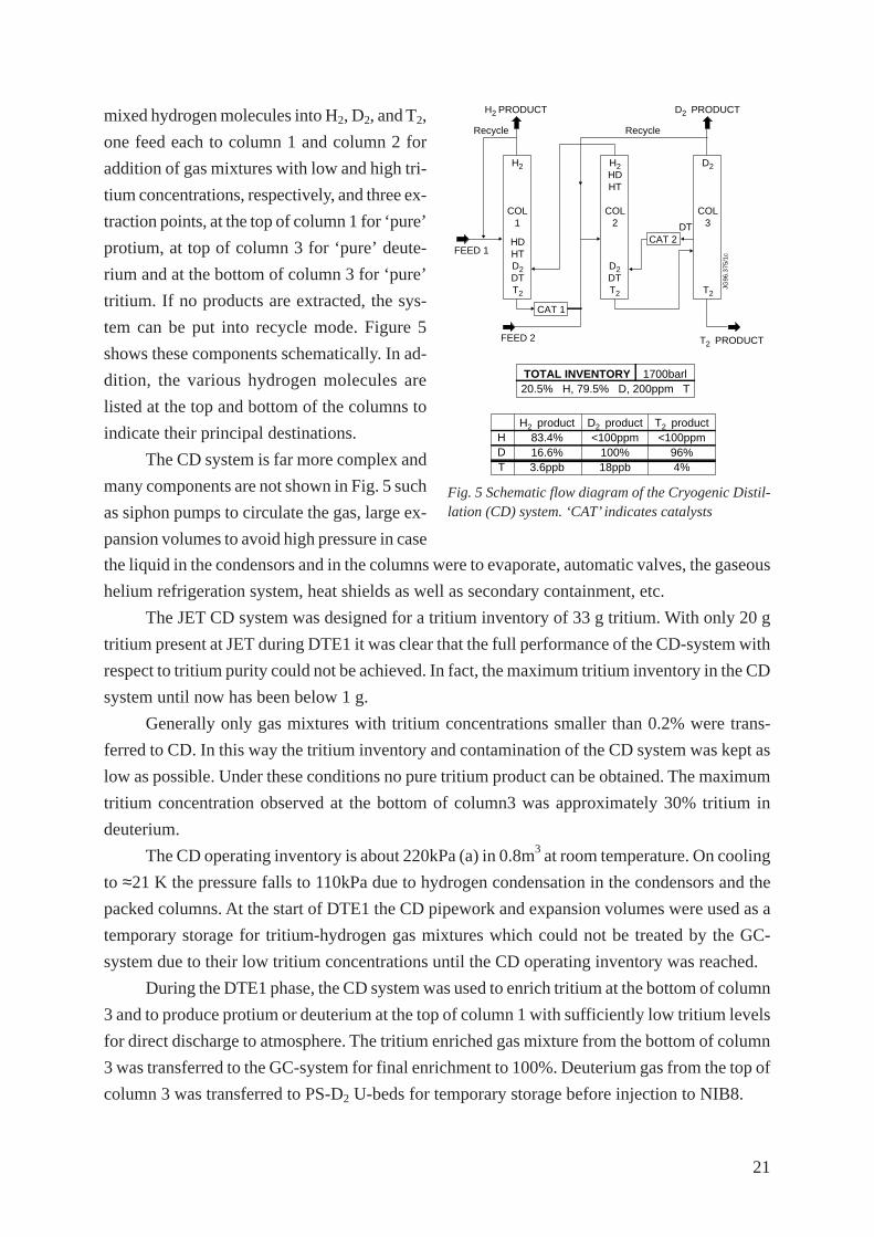
21
mixed hydrogen molecules into H2, D2, and T2,
one feed each to column 1 and column 2 for
addition of gas mixtures with low and high tri-
tium concentrations, respectively, and three ex-
traction points, at the top of column 1 for ‘pure’
protium, at top of column 3 for ‘pure’ deute-
rium and at the bottom of column 3 for ‘pure’
tritium. If no products are extracted, the sys-
tem can be put into recycle mode. Figure 5
shows these components schematically. In ad-
dition, the various hydrogen molecules are
listed at the top and bottom of the columns to
indicate their principal destinations.
The CD system is far more complex and
many components are not shown in Fig. 5 such
as siphon pumps to circulate the gas, large ex-
pansion volumes to avoid high pressure in case
H2
COL1
H2 HDHT
COL2
D2
COL3
CAT 1
CAT 2DT
FEED 1
FEED 2
Recycle Recycle
H2 PRODUCT D2 PRODUCT
T2 PRODUCT
JG96
.375
/1c
TOTAL INVENTORY 1700barl20.5% H, 79.5% D, 200ppm T
HDT
H2 product83.4%16.6%3.6ppb
D2 product<100ppm
100%18ppb
T2 product<100ppm
96%4%
HDHTD2 DTT2
D2 DTT2 T2
Fig. 5 Schematic flow diagram of the Cryogenic Distil-lation (CD) system. ‘CAT’ indicates catalysts
the liquid in the condensors and in the columns were to evaporate, automatic valves, the gaseous
helium refrigeration system, heat shields as well as secondary containment, etc.
The JET CD system was designed for a tritium inventory of 33 g tritium. With only 20 g
tritium present at JET during DTE1 it was clear that the full performance of the CD-system with
respect to tritium purity could not be achieved. In fact, the maximum tritium inventory in the CD
system until now has been below 1 g.
Generally only gas mixtures with tritium concentrations smaller than 0.2% were trans-
ferred to CD. In this way the tritium inventory and contamination of the CD system was kept as
low as possible. Under these conditions no pure tritium product can be obtained. The maximum
tritium concentration observed at the bottom of column3 was approximately 30% tritium in
deuterium.
The CD operating inventory is about 220kPa (a) in 0.8m3 at room temperature. On cooling
to ≈21 K the pressure falls to 110kPa due to hydrogen condensation in the condensors and the
packed columns. At the start of DTE1 the CD pipework and expansion volumes were used as a
temporary storage for tritium-hydrogen gas mixtures which could not be treated by the GC-
system due to their low tritium concentrations until the CD operating inventory was reached.
During the DTE1 phase, the CD system was used to enrich tritium at the bottom of column
3 and to produce protium or deuterium at the top of column 1 with sufficiently low tritium levels
for direct discharge to atmosphere. The tritium enriched gas mixture from the bottom of column
3 was transferred to the GC-system for final enrichment to 100%. Deuterium gas from the top of
column 3 was transferred to PS-D2 U-beds for temporary storage before injection to NIB8.
22
Only pure hydrogen gas must be injected into the CD system because otherwise blockage
due to frozen impurities can occur. In the AGHS U-beds are used as a source for CD, providing
ideal gas purity - hence no freeze-up occurred.
As mentioned above the volume of the CD system was used at the start of DTE1 first as a
storage volume. During the NIB8 intervention the gas was processed in CD, and discharged via
various routes and the CD system emptied again for the second phase of DTE1. CD was used
during the second part of DTE1 in a very similar way.
The performance of the JET CD-system allowed discharge of protium and deuterium to
atmosphere. This discharge route was very important because without it the storage capacities
of the AGHS for deuterium and protium would have been exceeded.
In summary, 1.364MPa.m3 of hydrogen gas were treated in CD during and after the DTE1
phase, 0.948MPa.m3 were discharged to the stack and 2.2 g (880Pa.m3) of tritium were ex-
tracted.
The hydrogen compositions achieved with the CD system at the various product extrac-
tion points show that in the H2 and D2 product extraction there was < 1 ppm tritium, this was
sufficiently low to allow discharge of 1 m3 of this gas within a few days.
The analysis of the product deuterium from top of column 3 showed very pure deuterium
with < 50 ppm (the detection limit) of protium. The purity of the deuterium produced in CD is
therefore far better than commercially available deuterium which shows as the main impurity
HD of concentrations of about 0.15%.
7.2.3 Complementary operation of and comparison between GC and CD
Deuterium product of the GC system which was not re-supplied to the users was transferred to
CD for further detritiation and for discharge to stack.
Tritium product from the CD system was sent to GC for final enrichment.
Deuterium and protium product of the GC system contained tritium concentrations too
high for direct discharge and were therefore sent to CD for detritiation and subsequent discharge
to the stack.
CD performance allowed discharge of protium- and deuterium-rich mixtures from the top
of column 1 to stack.
The operation of the GC system is simple. The switching of the valves can be done either
automatically or manually. Production runs for large amounts of tritium were done only in auto-
matic mode. The GC system is operational within approximately one hour. The GC process is a
batch process and requires regeneration of the columns at the end of each run.
The operation of the CD system is complex, as cascaded control loops lead to interde-
pendence of operating parameters. The system can be operated automatically or manually. In
many cases the system was operated in a mixed mode, meaning many parameters were in auto-

23
matic mode with a few fixed manually. Starting of the CD system and achievement of equilib-
rium conditions can take time. The CD-system can be used in batch or continuous mode opera-
tion.
Both hydrogen isotope separation systems were vital to cope with the gas quantities and
the total tritium inventories during the DTE1 phase. The GC system was used very often during
the ‘hot’ (D-T plasma) phase of DTE1, whereas CD was very important during the end of the
DTE1 phase, the clean-up period and the time of the return to D-D plasma experiments. The
GC-system was necessary to produce the required tritium purity and the CD system to produce
gas mixtures with tritium concentrations sufficiently low for direct discharge to stack.
7.3 Impurity Processing (IP) System
Gases which are not absorbed by the JET U-beds need to be detritiated because they contain
tritiated methane, higher hydrocarbons, etc., in addition to helium, argon, neon, nitrogen, etc.
The tritium in these impurities has to be recovered for re-use and to avoid tritium emission
to the environment. The removal of tritium from tritiated compounds is done in the IP system. A
simplified flow diagram of IP is shown in Fig. 6.
U-bed Fe-bed Cold trap Recombiner
Chemical Module Assembly
Buffer Pumping Box
Normetex pumps MechanicalForevacuum
Room
BufferTank2m3
He ED H2 O2 N2
IS
CFPSAN
JG98.106/7c
4 off 2 off
Fig. 6 Schematic flow diagram of the Impurity Processing (IP) system.
Gases which were not absorbed by U-beds in other subsystems of the AGH-plant were
collected, transferred to IP and compressed via the Normetex pumps into the 2 m3 tank or into
the manifold bypassing the tank if the gas amount to be processed was small.
Various methods exist for detritiation but the sample composition should be determined
beforehand in the analytical laboratory to select the best processing technique:

24
a) Circulation of the gas mixtures through a cold U-bed (at room temperature):
This method can be used when hydrogen forms a large part of the gas mixture.
Hydrogen will be absorbed by the U-bed when the gas mixture is circulated through the
cold U-bed via the Normetex pumps. The removal of hydrogen can be observed by a decrease of
the pressure in the manifold and the reduction of the tritium concentration by an ionisation
chamber.
b) Circulation of the gas mixture through a hot U-bed (~800 K)
If large amounts of hydrocarbons and only small amount of hydrogen are present in the gas
mixture to be processed, circulation over a hot U-bed will crack most of the hydrocarbons and
hydrogen will be liberated. Finally an equilibrium between the generated hydrogen and the final
composition of hydrocarbons will be reached, which can only be changed further by absorption
of the generated hydrogen in a cold U-bed. (See next Section).
c) Circulation of the gas mixture through a hot U-bed (~800 K) and a cold U-bed (at room
temperature) in series:
This method can be used when the gas mixture contains hydrogen and hydrocarbons.
Hydrogen already existing in the gas mixture is absorbed by the cold U-bed. The higher
hydrocarbons are cracked by the hot U-bed creating uranium carbide and hydrogen gas which is
absorbed in the cold U-bed. In this way the cracking of the hydrocarbons higher than methane
continues quantitatively because the generated hydrogen is immediately removed.
d) Addition of oxygen and catalytic combustion:
This is used if further detritiation of the gas mixture (e.g: with respect to methane) is needed.
Figure 6 shows the possibility to add various gases such as H2, O2, N2, to the 2 m3 tank.
The purpose of oxygen addition to the tank is to burn combustible impurities (hydrocar-
bons, hydrogen, etc.) in the hot recombiner to water and CO/CO2. A disadvantage is that large
amounts of water are created and the U-beds used for cracking the water are used up by the
irreversible reaction to uranium oxides.
To avoid the generation of explosive gas mixtures via the addition of oxygen, helium is
added first to the gas mixture and oxygen only in small batches. On the hot recombiner hydro-
gen and hydrocarbons are burnt to water and CO/CO2. The water is collected in a cold trap at
160 K. The process of detritiation and collection of the water on the cold trap can be seen by the
drop of the ionisation chamber signal. The detritiated gas mixture containing inert gases, N2, O2
and CO/CO2 is finally discharged via ED to the stack.
The cold trap is slowly warmed up, the water vapour cracked on a hot U-bed and the
liberated hydrogen absorbed on a cold U-bed.

25
Hydrogen gas recovered and stored in a IP U-bed was transferred to one of the IS U-beds
and fed to one of the two hydrogen isotope separation systems for isotopic separation.
Four U-beds are available in IP to crack water, hydrocarbons and to store hydrogen (see
Fig. 6). The hydrogen capacity of these U-beds was checked again after the Remote Tile Ex-
change was started and most of the gases in AGHS were treated. High reductions of hydrogen
absorption capacities of up to 83%, 48%, 22% and 3% were observed for UB-1, UB-2, UB-3,
UB-4.
An effort was made to determine the concentration of impurities in the gases pumped from
the torus systems during the second phase of DTE1 (week 38 to week 47 inclusive). The total
gas quantity of impurities collected from the torus systems and AGHS was 7640Pa.m3 which
corresponds to 3.7 % of the total gas processed during that period. The compositions for the
impurities are listed in Table 6. The impurities were determined with the analytical gas chroma-
tograph. It must be noted that the Flame Ionisation Detector used in the Analytical Gas Chroma-
tograph [7] underestimates the concentrations of tritiated hydrocarbons and that also very broad
peaks were observed with very high retention times which could not be assigned to the available
gas mixtures. These peaks are believed to be caused by hydrocarbons CnQm with n > 3.
A more detailed description of the performance of the IP system is given in [3].
Table 6: Composition of impurities pumped from the torus systems from week 38 - 46 in 1997.
ytirupmI %lovnoitartnecnoC
eH 16.1
N2 52.0
O2 rA+ 220.0
OC/OC 2 930.0
ruopavretaw 2.1
QC 4 493.0
C2Q2 630.0
C2Q4 920.0
C2Q6 130.0
C3Q8 840.0
latot 7.3
7.4 Mechanical Forevacuum (MF) system
The Mechanical Forevacuum was used to pump the torus, NIBs and AGH-subsystems from
atmosphere to low vacuum and to transfer gases between various AGH-subsystems. Further-
more, MF was always ready to start evacuation of the torus or of the NIBs in case a major leak
occurred [22], [23].

26
Figure 7 shows schematically how the
various pumps, Normetex pumps (PUNs) and
roots pump (PUR) are interconnected. Depend-
ing on the operational needs the pumps of MF
can be run in parallel or in series to achieve a
large throughput or a very low base pressure.
About 14 and 8 hours were needed to
pump down the torus and NIB volumes from
atmosphere, respectively. Normally pumping
was started with two 150 m3/h Normetex pumps
in parallel (see Fig. 7). If the pressure in the
torus or the NIB was below 70kPa, only the
600 m3/h pump was used until the pressure is
below 20kPa where one of the 150 m3/h pumps
is turned on to back-up the 600 m3/h pump.
Below 100Pa the 1000 m3/h roots pump with a
150 m3/h Normetex pump and the two
other Normetex pumps were used in parallel
(see Fig. 7).
MF was very heavily used during the
NIB8 intervention [17]
Toruscrown
NIBcrown
IP/AN/CF
IP/AN/CF
ED
ED
CF
ML1
ML2
PUR1000 m3/h
PUN150 m3/h
PUN150 m3/h
PUN600 m3/h
JG97
.416
/6c
Fig. 7 Schematic flow diagram of the MechanicalForevacuum (MF) system.
a) to pump the water vapour from the NIB8 cryo-pump,
b) to pump N2 from NIB4 and NIB8 after extended soak times before their opening,
c) to purge NIB4 and NIB8 with air,
d) to keep the interspaces of the rotary valves between NIB4/NIB8 and torus differentially
pumped,
e) to evacuate the NIB4 and NIB 8 after the NIB8 intervention.
MF and ED were the subsystems of the AGHS which were most heavily involved in the
NIB8 intervention. Both systems coped very well the various demands and contributed to the
very efficient and timely completion of the intervention.
7.5 Analytical Laboratory
Gas samples from almost all AGH-subsystems can be moved to the analytical laboratory via
connecting pipework for analysis with different methods: ionisation chambers for low and high
tritium concentrations, omegatron, residual gas analyser (quadrupole), katharometers and ana-
lytical gas chromatograph.
The main part of the analytical laboratory is the analytical glove box which is subdivided
into three separate containments: The analytical section houses the ionisation chambers and the
analytical gas chromatograph. The Make-up box houses the katharometers for checking the

27
product quality of CD and allows connection of the Amersham U-beds for transfer of tritium to
the process pipework of AN. These two compartments are the only ones in the AGHS perma-
nently equipped with gloves. In the third section all pumps necessary for the mass spectrometers
are located. The Omegatron and the quadrupole are placed inside a ventilated hood. This was
permitted because due to the very low pressures the risk of a tritium release is very low. In
addition, the air in the fume hood is monitored by an ionisation chamber. Upon observation of
tritium concentrations slightly above detection limit in the hood, the extracted air would be
switched to ED for detritiation.
318 analyses were performed with the analytical gas chromatograph (AN-GC) during and
after DTE1 up to the start of the remote tile exchange. The analytical laboratory played a very
important role in characterisation of the various products and processes. Detailed description of
the AN-GC and of results obtained are published elsewhere in this volume [7].
7.6 Exhaust Detritiation (ED) system
Almost all gases to be discharged from the AGHS have to pass through the Exhaust Detritiation
system for further detritiation. The ED system has a design detritiation factor of 1000. A detailed
design overview of the ED system is given in [24].
The detritiation is achieved by burning hydrogen and hydrocarbons in hot recombiners to
water and by trapping water on dry molecular sieves. The humidity levels of the gas exiting the
driers is continuously monitored. When the humidity reaches a dew point of (-60 °C) the standby
drier unit is switched in and the saturated drier is regenerated. At various places, e.g. before and
after the recombiners, water condensors are installed with the purpose to reduce the air dew
point to 4 °C in order to minimise the water load on the driers.
Under normal circumstances (e.g. no maintenance performed in AGHS and no elephant
trunk used) the capacity of one drier bed was sufficient for up to 3 weeks of operations.
The ED system can be bypassed by discharges through a 10m3 tank B4. This was often
done for the exhaust gases of the analytical GC system [7] and for protium gas from top of
column 1 of CD (see Section 7.2.2). In both cases this bypass was only selected when the tritium
concentrations were known to be very small. In addition, the tank B4 is equipped with an ioni-
sation chamber and software and hardwired interlocks which would switch the discharge route
to ED on a high ionisation chamber reading.
Operational experience on the ED system has been discussed in [25].
Until now the ED system was used very heavily during the NIB8 intervention and the
Remote Tile Exchange which followed operations in February 1998 [26]. During the NIB8
intervention the driers had to be regenerated sometimes after only about 8 to 12 hours. To in-
crease the duty time of a drier the driers were run with dew point far higher than (-60 °C) and
were changed depending on the increase of the ionisation chamber reading at the outlet of the
ED system.

28
Very sensitive ionisation chambers monitor the tritium levels at the inlet and the outlet of
EDS. High tritium concentrations were observed in the inlet with almost no tritium concentra-
tions above background at the outlet.
The water generated in ED is collected in a 4 m3 tank. Low tritiated water (< 5 GBq/m3) is
filled into a special bowser and the water handed over to the JET Waste Management Group.
Highly tritiated water up to 800TBq/m3 is filled into 200 L drums for shipping to CFFTP in
Canada for detritiation. Even higher tritium concentrations must be diluted before any removal
from the 4 m3 tank.
At present a design study is in progress to explore the possibility of treating aqueous
tritiated waste on-site by addition of a Combined Electrolysis Catalytic Exchange (CECE) mod-
ule to existing equipment (CD, GC, ED).
7.7 NIB8 Intervention
During DTE1 on the 4 June 1997 a small water leak was observed in NIB8 which stopped
further operation of the neutral beam injection. Manual intervention was necessary. At that time
about 11 g of tritium had been supplied to NIB8. The intervention is described in detail in [6],
[17].
NIB8 cryopump was warmed up to 77 K and the gases released at 77 K were pumped with
CF. After a warm-up of the NIB8 cryopanels to ambient temperature, the moist air was pumped
with MF directly into ED. A N2 stream was added in MF to purge the water at the outlet of the
Normetex pumps to ED and to avoid condensation at the outlet of the pumps due to the atmos-
pheric pressure.
The torus was filled with 15kPa of pure nitrogen to avoid any ingress of air after opening
the NIBs to atmosphere due to potential leaks in the rotary valves separating torus and the NIBs.
During the whole NIB8 intervention the interspaces of the two rotary valves were almost con-
tinuously pumped by MF.
NIB4 and NIB8 were filled first with nitrogen gas, allowed to soak for certain times and
then evacuated again by MF into ED. This allowed to establish the tritium concentrations. After-
wards air was used instead of nitrogen and finally NIB4 and NIB8 were purged by turns for
hours. During these purges the MF system was bypassed and flows of generally more than 250
m3/h were achieved by the blowers of ED.
The Injector central column [6] of NIB4 which carries the deflection magnets and the ion
dumps and which was not directly exposed to tritium was moved into a ventilated plastic tent in
the main assembly hall and the more contaminated column of NIB8 transferred to NIB4 where
the existing Injector Box envelope acted as the secondary containment. Access for repair inside
NIB8 was made via a specially constructed access cabin [17]. Access in pressurised suits was
allowed for tritium concentrations <100 DAC.

29
During this repair work which lasted five weeks, ED supplied the necessary ventilation
and detritiation of the air. Daily regeneration of the drier in duty were necessary. The water
amount collected by ED was about 50-60 kg per day. The total tritium activity collected during
the NIB8 intervention was 29 TBq in 1.78m3 water. The total tritium release due to the NIB8
intervention was a few percent of the monthly discharge authorisation for HTO.
7.8 Secondary containments of the AGHS
Process pipework of the AGHS and in the supply lines/gas distribution modules in the Torus
basement (Fig. 1) with internal operating gas pressures larger than 100 mbar is surrounded by
secondary containment. The purpose of the secondary containment is to capture tritium leaked
or permeated from process pipework and to protect workers and environment. Only the long
evacuation pipework between the torus systems and CF/ MF are not secondary contained be-
cause the normal operating pressure is below 1Pa and during regenerations of the torus and NI
systems cryo-pumps pressures are limited to 1kPa.
Secondary containments on the JET AGHS are either evacuated or filled with nitrogen,
helium or argon. If a whole room functions as the secondary containment, e.g. the room contain-
ing the large Normetex pumps and the Exhaust Monitoring System (EMS), air is the atmosphere
of the secondary containment.
The most common secondary containments are the N2 filled valve boxes which do not
contain any gloves. These boxes are kept at a pressure between -3kPa and -1.7kPa with respect
to atmosphere. Downstream and upstream ‘Donkin’ valves are used to keep the pressures be-
tween these limits. If the pressure goes below -3kPa, N2 is allowed to enter the box; if the pres-
sure goes above -1.7kPa the upstream pressure regulator opens and gas is moved to ED.
Only the analytical glove box and the Make-up box have gloves to allow operator manipu-
lation inside the boxes. The N2 atmosphere is controlled between -400 and -200Pa.
In the CD system the secondary containments of the instrument and valve box are filled
with helium of 180-220kPa (a). Due to the very high leak tightness of the secondary contain-
ment the pressure in these boxes stays constant. Alarms are created on the annunciator panel if
the observed pressure deviates from the set value within certain limits.
After installation and connection of the boxes in the AGHS they were leak tested to the
specification that starting at a pressure of -3kPa, the pressure rise observed during 24 hours must
be smaller than 1kPa. During these tests correction was made for temperature and atmospheric
pressure changes.
The boxes were purged once per day with N2 to dilute possible inleakage of air. The
oxygen level in the boxes was checked at regular intervals and found to be less than 0.5%.
The N2 filled secondary containment boxes are equipped with JET designed ionisation
chambers with Overhoff preamplifiers [27]. The lower detection limit is about 0.1 to 1 MBq/m3.
Any tritium leak rate is integrated for one day due to the selected purge interval of 24 hours.

30
Due to the very high leak tightness of the process pipework no tritium leaks into second-
ary containments of N2 filled boxes were observed during the DTE1 phase which would have
required operator intervention.
Major tritium concentration of up to 1000 DAC have been observed only in the secondary
containment of the Make-up box of the AN glove box during the transfer of tritium from li-
censed Amersham U-beds to PS-T2. The Amersham U-beds have no secondary containments.
After a certain time of heating depending on the history of the U-bed and on the tritium pressure
inside the U-bed a high permeation rate of tritium is observed which caused the high DAC
values and internal contamination of the box. The Make-up box of AN is the only N2 filled
secondary box of AGHS which shows internal tritium contamination.
8. TRITIUM ACCOUNTANCY
The tritium amounts transferred to the AGHS were measured very accurately with precision
calorimetry and (PVT-c) measurements. The relevant numbers were given in Section 5.
The tritium amounts moved via GI and GD to the users were also determined very accu-
rately by (PVT-c) measurements.
The tritium amounts pumped back from the torus and the NIB cryo-pumps were also
determined, but due to the very large volumes involved, different temperatures of the gas streams
(room temperature and 77 K), small total gas amounts and the use of ionisation chambers at low
and varying pressures (IC-current is a function of many parameters including pressure, gas com-
position, and applied voltage) the accuracy of these measurements was limited. They were used
however to give a daily information of the tritium inventories in various subsystems.
For accurate determination of the tritium inventory during DTE1 the total tritium inven-
tory in the AGHS was determined at least every second week in the following way:
a) Tritium gas mixtures were enriched with the GC-systems to nearly 100%. The enriched
tritium was collected in one of the PS-T2 U-beds. The result of this undertaking should be
that only small amounts of tritium gas mixtures exist in various subsystems, mainly the
GC system, because the interfractions are an unavoidable by-product of a GC separation
run.
b) The tritium content in the PS-T2 U-bed was determined by desorbing its content and per-
forming (PVT-c) measurements using the 100 L assay volume with precision thermom-
eter, pressure gauge and AN-GC analysis.
c) The tritium content in gas mixtures of the other subsystems was also determined via (PVT-
c) measurements.
Best results are obtained with the above methods when most of the tritium was moved into
GC for isotopic separation and almost no gas needs to be determined under section c).
The main finding was that a significant fraction of the available tritium (20 g) was not
recovered in the AGHS, but was trapped in the torus systems [20].

31
Table 7 shows the tritium inventory calculated for torus and NIBs by subtraction of the
measured tritium inventory in the AGHS from the total decay corrected inventory on site as a
function of various dates when the inventory snapshots for the AGHS were performed. 6.2g of
tritium were still retained in the machine at the start of the Remote Tile Exchange (RTE). Most
of the tritium was held up in the torus internal surfaces [20], with very little in the NIB [6].
Table 7: Tritium Inventory in Torus and NIBs
MUTAD gnisBIN/surotnimuitirT
79yluJ11 9.2
79rebmetpeS41 3.2
79rebmetpeS72 3.3
79rebotcO6 3.5
79rebotcO31 8.7
79rebotcO12 5.7
79rebotcO82 6.7
79rebmevoN4 4.8
79rebmevoN11 0.01
79rebmevoN12 4.8
79rebmeceD01 3.7
89yraunaJ41 8.6
89yraunaJ72 2.6
In-situ transient adiabatic/isothermal calorimetry [28] can be performed with the PS-T2
U-beds. Additional thermocouples are installed for determination of the temperature rise due to
the tritium decay heat. Transient adiabatic conditions are observed because the primary process
volume is surrounded by an intermediate and secondary containment which are both continu-
ously evacuated. Isothermal conditions are achieved after cooling the U-beds for long times (15
hours) with gaseous nitrogen of room temperature. After cooling has stopped the temperature
rise is observed for a few hours and the tritium content determined from the slope of the tem-
perature rise. During the cooling and measurement phases no other work is permitted in PS-T2
to avoid any temperature changes which means that PS-T2 is not available for other tasks during
these times. Due to these facts the in-situ calorimetric determinations were performed more out
of scientific interest than operational necessity. The agreement between the calorimetric results
and (PVT-c) measurements was generally better than 10%.

32
9. CONTROL AND INTERLOCK SYSTEMS OF THE AGHS
9.1 AGHS control system
The main control system of the AGH-plant is a Distributed Control System (DCS). In addition,
two AGH-subsystems (CD and ED) are operated by Siemens PLC.
These control systems are used to control the various processes, to recognise process pa-
rameters which are drifting outside normal operating boundaries, to bring those parameters back
into totally safe conditions or to stop these processes. 436 static software interlocks are installed
in the DCS.
9.1.1 Distributed Control Systems (DCS)
The DCS from Fischer and Porter is connected to 3600 inputs and outputs. There are 414 ana-
logue inputs. Control of the plant is split up between 17 Distributed Control Units (DCU-2000s).
Within these DCUs, there are 140 automated sequences and 51 analogue PID loops.
Each DCU controls its section of plant independently. If there is a communications fail-
ure, or a failure of one control unit or miniframe, control for the rest of the plant is unaffected.
Four additional controllers, µDCI-4000s, are connected to the GC columns, and are used
for fast switching during hydrogen isotope separation runs. They communicate to one of the
DCU-2000s via an RS-485 serial link.
The DCUs are connected to a dual ETHERNET highway. The DCUs are interrogated by
four PDP-11 miniframes, DOC 2500s, which each drive two operator consoles (total of eight
consoles).
There are 123 graphics which can be accessed from any of the eight consoles. These are
used to monitor and operate the plant.
Analogue inputs are recorded on trend displays. These displays are split up between the
DOCs. There are 343 displays, trending a total of 975 points.
Part of the system consists of a new DCS, a SYSTEM SIX UNIX miniframe (the AP-6400
from Elsag-Bailey). This has been connected to the ETHERNET highway and has 24 trend
displays, trending a total of 90 points. The AP-6400 drives two UNIX terminals, which display
graphics and trends.
Another PDP-11 miniframe (CEU-2500) is also connected to the highway. Both the AP6400
and the CEU-2500 periodically schedule programs written in C to perform calculations such as
the conversion of the measured ionisation chamber current into tritium concentrations, and tri-
tium inventory calculations.
Complex sequential control that is deemed to be non-real-time and non-safety critical, is
also carried out by periodically scheduled C programs in the CEU-2500, and sequences in a
SYSTEM SIX Distributed Control Unit. (DCU-3200).
The Control and Data Acquisition System (CODAS) is a large UNIX based system cus-
tom built by JET [29]. It acts as a site wide control system. The AP-6400 has a dedicated
33
ETHERNET TCP/IP link to the CODAS system. Customised software enables two-way trans-
fer of data between the AGHS plant and plant elsewhere on the JET site.
9.1.2 Stand-alone PLCs in AGHS
There are two Siemens S5-135U PLCs, which control the CD subsystem and the ED subsystem.
Both have a single screen which can be used to display simple graphics and trends. These PLCs
communicate to the Fischer and Porter system via separate RS-485 serial links.
9.2 Hardwired Interlock System of AGHS
A special hardwired interlock system was installed to turn off equipment (e.g. pumps, heaters)
or to put valves into their fail-safe position on approaching process parameters exceeding de-
fined operating limits and to alert the operator via audible and flashing alarms on a annunciator
board in the AGHS control room. 159 hardwired interlocks are used in the AHGS. All hardwired
interlock latch and continuation of the work is only possible after cure of the wrong process
parameters. The hardwired interlocks can be split into three categories and are distinguished by
their colour on the annunciator panel: red for imminent or actual tritium release requiring imme-
diate operator action; yellow for potential tritium release; and white for warning only.
The hardwired interlock system employs only very simple electrical circuits such as re-
lays to achieve a very high reliability of the system. Programmable integrated circuits were not
permitted.
The hardwired interlocks were tested at least annually. If the operations program allowed
the tests were performed every 6 months.
Every hardwired interlock is used to back-up a software interlock. The setpoints of the
software interlocks were chosen such that the software interlock cuts in earlier than the hardwired
interlock. In this way hardwired interlocks are almost never triggered.
10. SERVICES SUPPLIED TO THE AGH BUILDING
10.1 Ventilation system
The AGH-building has a once through ventilation system which holds the building under a
slight under-pressure (-100 Pa) with respect to atmosphere. Extracted air is discharged to atmos-
phere via a monitored stack at a normal flow rate of 11 m3/sec resulting in about 10 air changes
in the main hall per hour. Containment between rooms is maintained by varying the under-
pressure to provide air flow from clean areas towards less clean ones.
If a tritium leak is observed in the main hall of the AGHS an emergency fan is added to the
normal running fan to provide an enhanced air change rate of double the normal (20 air changes
per hour). To provide the increased air flow dampers open in the building envelope.
The building ventilation also provides the ventilation for the air lock to move large equip-
ment in and out of the building, for slightly tritiated waste stored in front of the AGH-building
and for the NIB auxiliary ventilation system (see Fig. 1).

34
Several tritium handling facilities have an emergency clean-up system where the building
air is circulated through a dedicated tritium clean-up system after a tritium release into the build-
ing. These clean-up systems are large to achieve tritium removal in a short time to reduce con-
tamination of the building.
At JET this philosophy is only taken up partly for the small rooms which contain the
impurity processing system, the analytical laboratory, product storage and the large Normetex
pumps. In case tritium is observed in one of these rooms, the ventilation of this room is stopped
and the room connected to the ED system via an existing elephant trunk ventilation duct. The air
of the room is moved to ED for detritiation and then discharged into the environment.
10.2 Other services supplied to the AGHS
The AGH-building uses the following services supplied by other groups at JET:
i) Electrical power
The electrical power supply feeds to the AGH-building comprises three power distributions: a)
to AGHS process equipment, b) to AGHS building services, ventilation, air compressors and
chilled water equipment, and c) to the un-interruptable power supply (UPS).
The following AGHS essential equipments are supplied by more than one power supply
feed to improve availability in the event of power supply interruptions: a) AGHS UPS, b) ED
system, and c) air compressor control panel.
ii) Chilled and cooled water
Two water cooling circuits are used in the AGHS, one with chilled water at 4 C and one with
cooled water at 16 C.
Chilled water is used in the various water condensors in MF and ED and to cool-down
secondary containments. Low water temperature is needed in the condensors to achieve a low
humidity of the air leaving the condensors and therefore a low water load on the driers.
Cooled water is used for various pumps, the turbines of the CD He-refrigerator and the
aftercooler of its He compressor,
iii) Compressed air
Compressed air of 8 bar is supplied by three compressors, one always on duty, one in standby,
and one as reserve or in maintenance. In addition, if all three fail, a backup system is available at
6 bar which needs to be connected manually.
iv) Nitrogen gas at 400kPa
Nitrogen at 400kPa for U-bed cooling, purge of secondary containments, etc., is available from
a nitrogen ring manifold which is supplied by boil-off gas from liquid nitrogen.

35
v) Liquid nitrogen
Liquid nitrogen from the JET cryoplant is supplied via long cryo-transfer lines to the 0.5m3
storage tank in the AGHS hall and from there to the various systems using liquid nitrogen such
as CF, IP and AN-GC.
vi) Liquid helium
Liquid helium from the JET cryoplant is supplied via long cryo-transfer lines to the 2m3 storage
tank in the AGHS hall and from there via the liquid helium distribution box to the ten cryopumps
of CF.
11. FAILURE OF EQUIPMENT IN AGHS DURING DTE1
In general, operation of the AGHS was highly reliable during the whole of 1997 and 1998. In the
following only repairs performed during the main DTE1 phase whilst D2 and/or T2 were sup-
plied to the users are discussed.
11.1 Bearing problem of one of the three blowers of ED
A blower/fan in the ED system became very noisy and showed strong vibrations.
The blower was dismantled and the new bearing installed, but the new assembly failed
again because the old bearing had slightly worn out the bearing sleeves. The complete replace-
ment of the bearing and housing solved the problem.
11.2 Butterfly valves in ED
Butterfly valves are used in ED due to limited space. The open/close mechanism of these valves
was found not to function correctly and finally the valve seats became almost immobile.
Examination of the valves revealed corrosion effects due to high humidity with the effect
that the valve actuating mechanism became stiff and finally seized. In one of the valves the shaft
which operates the sealing disc was found to be broken. As a short term solution these valves
were exchanged on all driers of ED with new ones, but the long term solution will be to use a
different type of corrosion resistant valve. A totally new valve means a modification of the ED
system which has to be assessed and approved by the modification approval procedure [22].
Before the breach of the process pipework the ED driers had to be purged thoroughly. No
tritium contamination of the interior pipework was observed by smear test as well as no airborne
tritium activity.
11.3 Oil circulation pump of the GC system
The columns of the GC system are regenerated by heating the heat transfer fluid (a special oil)
normally to 200° C and in special cases to 300° C. This is done by circulation of the oil through
a heater and a heat exchanger by means of a dedicated oil circulation pump.

36
On one occasion it was found that the oil pump could not be started. The drive motor was
found to be the problem, but due to the construction of the pump the motor could not be ex-
changed.
The oil was checked for contamination with tritium with a null result. This was expected
from the design which had separated the Pd filled columns from the oil filled columns by a 1
mm wide gap filled with the nitrogen. As a result the oil pump could be removed without the
establishment of a controlled area.
A new pump was ordered and installed within a few days. The DTE1 program was not
delayed by this problem.
11.4 Exchange of a Helicoflex seal in one of the Normetex pumps of IP
A tritium leak was observed at the outlet of one of the IP Normetex pumps. The leak was finally
identified by using a He leak detector. The leaking Helicoflex seal was exchanged.
With the new seal installed the Normetex pump was again leak tight. The occurrence of
this leak was probably caused by high humidity at the outlet of the pumps (in the IP process
water is created by design) which caused corrosion of the helicoflex seal liner (aluminium). A
new helicoflex seal with a Ag liner was installed to prevent repetition of the problem.
11.5 Leak in a valve of PS-T2
Just before the start of DTE1 a small leak was observed in the PS-T2 U-bed outlet manifold with
tritium pressures above 150kPa (a). The bellow of the boundary valve of UB-5 (see Fig. 2) was
identified as the cause of the leak. The maximum leak rate observed with a He leak detector was
in the 10-9Pa.m3.s-1 range. The valve was not replaced due to the imminent DTE1 phase, but the
usual Cajon seal was replaced by a blind disc and the compressed air supply to actuate the fail
closed valve was removed. In this way the leak of the bellow could not come in contact with any
tritium. The disadvantage was that only three of the four PS-T2 U-beds were available for the
DTE1 phase with UB-5 (see Fig. 2) acting as a back-up.
12. SUMMARY OF THE EXPERIENCE WITH THE AGHS DURING DTE 1
12.1 General
All subsystems of the AGHS performed very well during and after DTE1. The AGHS fulfilled
all requirements (such as supply of pure tritium, tritium storage, pumping, hydrogen isotope
separation, detritiation of impurities, purging, pump down from atmospheric pressure, discharges
of protium and deuterium, etc.) during normal operation of the torus and during repairs of equip-
ment connected to the torus. A further very important point is that all subsystems designed,
constructed and commissioned were in fact used during DTE1 and were necessary for the func-
tioning of the whole AGHS and the processing of the gases.

37
This is the result of a good design, careful inactive and active commissioning, the installa-
tion of necessary modifications and a well trained and dedicated staff.
The shift teams were able to maintain the plant. The highest dose received by one member
during one of the maintenance jobs was 85 µSv [27].
No unauthorised or unplanned tritium releases occurred inside the AGHS or via the stack.
Any tritium discharges were far below the approved daily tritium release limit.
The AGH plant can therefore supply with confidence the requested services for further
future deuterium tritium experiments (e.g. DTE1b, DTE2).
The AGHS demonstrated for the first time that tritium in large amounts can be processed
and recycled in an efficient and safe way during a tritium phase of a large fusion machine. This
is an important step on the way to the use of fusion machines for energy production.
12.2 Tritium Releases From JET Site
Tritium released into the environment is measured in the various stacks at JET. From 7 May
1997 (before start of DTE1) until 9 February 1998 (after start of remote tile exchange) 1.6 TBq
of HTO and 1.49 TBq of HT and other tritiated gases were discharged from the AGH-building
into the environment. These numbers are to be compared with the annual (monthly) discharge
authorisation of 90 TBq (20 TBq) for HTO and 110 TBq (25 TBq) for HT and others.
The discharges were from gas streams where further detritiation was not practicable (e.g.
contaminated gas from impurity processing system, product from top of column 1 of CD, sam-
ples analysed in AN-GC), and from repairs on torus systems.
12.3 Areas Of Improvements In AGHS
12.3.1 Accountancy
Day by day accountancy, especially of the gases pumped back from the torus systems was inac-
curate due to the pressure gauges used, small gas quantities and the very large volumes in-
volved.
Improvements could be made by the use of capacitance manometers which would also be
of advantage in various AGH-subsystems.
12.3.2 Ionisation Chambers
The interpretation of ionisation chamber readings was found to be difficult due to their depend-
ence on pressure.
This could be corrected for by using ionisation chambers in combination with pressure
gauges and implementing correction factors in the software.
However, further ambiguities arising from the gas compositions, dependent sensitivity
and contamination effects would still remain a problem.
38
12.3.3 Transfer of gas from CF to IS
The transfer of gas from CF to IS was the main bottleneck in the AGHS.
Installation of pumps in the three transfer lines between CF and IS to evacuate the large
CF volumes and to compress the gas into the IS U-beds would reduce the time needed for
transfer drastically.
12.3.4 Restricted use of manifolds
A few manifolds, e.g. the PS U-bed outlet manifolds, were used during the day’s operation to
supply gas to the users and during the night shift to pump the unused gas back to PS. At the same
time these manifolds were needed to remove blanketing gas from U-beds in PS used to absorb
gas enriched in CD and GC. These processes could not be done at the same time.
Installation of new pipework in PS and other systems would help to solve this problem.
12.3.5 Impurity Processing system
One of the main disadvantages of the JET impurity processing system is the consumption of
uranium by cracking water and/or hydrocarbons and the formation of uranium-oxide and/or
carbide. For further processing in IP the spent U-beds are to be replaced by fresh ones. The
consumed beds have to be treated as special waste due to their uranium content and the addi-
tional contamination by tritium.
In recent years large progress has been achieved in the processing of tritium containing
impurities. Total detritiation factors of up to 108 seem to be possible for integral process con-
cepts in ITER [30].
As mentioned in Section 7.3 high reductions of hydrogen absorption capacities of up to
83%, 48%, 22% and 3% were observed for UB-1, UB-2, UB-3, UB-4 in the JET IP system. Both
UB-1 and UB-2 need replacement before the start of the next tritium experiment.
The best solution is to modify parts of IP such that modern techniques can be used which
do not need any U-bed replacement.
12.3.6 Further Enhancements Of The AGH-Plant
The full operation of all AGH-subsystems highlighted the possibility of simple installations
which can accelerate and simplify the processing of the various gases.
Only a few of these possible enhancements will be mentioned here. They include the
installation of: new pipework in CF to by-pass the large expansion volumes; mass flow control-
lers in GC to achieve constant flows during separation runs; ionisation chambers of higher sen-
sitivity and lower contamination memory effects in CD; a new interconnecting line between
bottom of column 3 of CD and GC for transfer of not fully enriched tritium; a new pumping
circuit for PS-D2 to avoid cross contamination between the deuterium and tritium systems of PS;
more accurate flow meters and new non-corroding valves in ED to avoid the regular exchange
of the valves now installed; and new liquid helium transfer lines to the JET cryoplant to reduce
helium consumption.
39
REFERENCES
[1] The JET Team, ‘Fusion Energy Production from a Deuterium-Tritium plasma in the JET
Tokamak’, Nuclear Fusion 32 (1991) 967.
[2] A Gibson and the JET Team, Physics of Plasmas 5 (1998) 1839.
[3] A Perevesentsev et al., ‘Operational Experience with the JET AGHS Impurity Processing
system during and after DTE1’ - this volume.
[4] N Bainbridge et al., ‘Operational Experience with the JET AGHS Cryo Distillation sys-
tem during and after DTE1’- this volume.
[5] R Lässer, A C Bell, N Bainbridge, D Brennan, L Dörr, J L Hemmerich, S Knipe, R Stagg:
‘The Preparative Gas Chromatographic System for the JET Active Gas Handling System
- Tritium Commissioning and Use’ - this volume.
[6] T T C Jones at al., ‘Tritium operation of the JET Neutral Beams systems’, this volume.
[7] R Lässer, A C Bell, B Grieveson, J L Hemmerich, R Stagg, G V Atkins: ‘The Analytical
Gas Chromatographic System of the JET Active Gas Handling System - Tritium commis-
sioning and use during DTE1’, this volume.
[8] J L Hemmerich, A C Bell, P Boucquey, C Caldwell-Nichols, P Chuilon, F Delvart,
B Grieveson, R Haange, G Jones, R Lässer, M Laveyry, J Lupo, J Mart, P Milverton,
J-L Salanave, L Serio, N Skinner, R Stagg, K D Walker, J Yorkshades, A Konstantellos,
E Küssel: ‘Installation and Inactive Commissioning of the JET Active Gas Handling Sys-
tem (AGHS)’, 15th IEEE/NPSS Symposium on FUSION ENGINEERING, 1993, Hyannis,
Massachusetts, p. 37 - 41.
[9] A C Bell, J L Hemmerich, R Lässer, N Bainbridge, G Bishop, D Brennan, C Caldwell-
Nichols, J Campbell, A Dearden, B Grieveson, G Jones, J Lupo, J Mart, A Perevezentsev,
N Skinner, R Stagg, K Walker, R Warren, J Yorkshades: Status of the JET Active Gas
Handling System and Plans for Tritium Operation, Fusion Technology 28 (1995) 1301-
1306.
[10] J Lupo, J L Hemmerich, R Lässer, J Yorkshades, J-L Salanave: ‘The Impurity Processing
System for the JET Active Gas Handling System - Inactive Commissioning’, Fusion Tech-
nology 28 (1996) 1347-1352.
[11] R Stagg, J L Hemmerich, R Lässer, M Laveyry, J Lupo, P Milverton, N Skinner,
A Perevezentsev: ‘The Intermediate and Product Storage Systems for the JET Active Gas
Handling System - Inactive Commissioning’, Fusion Technology 28 (1995) 1425- 1430.
[12] D Ulrich, P Chromec: ‘Process and Safety Aspects of the Cryogenic Distillation System to
Process Hydrogen Isotope Feeds at JET’, Fusion Technology 21 (1992) 891-895.
P Boucquey, C Morf, F Delvart, J Mart: ‘Progress of the Inactive Commissioning and
Upgrade of the JET Cryogenic Distillation System’, Fusion Technology 1994, Proceed-
ings 18th SOFT 1994 Karlsruhe, Vol2, p. 1055-1057.

40
[13] R Lässer, G Jones, J L Hemmerich, R Stagg, J Yorkshades: ‘The Preparative Gas Chroma-
tographic System for the JET Active Gas Handling System - Inactive Commissioning’,
Fusion Technology 28 (1995) 681 - 686.
[14] R Lässer, B Grieveson, J L Hemmerich, R Stagg, K Walker: ‘The Analytical Laboratory
for the JET Active Gas Handling System - Inactive Commissioning’, Fusion Technology
28 (1995) 1033-1038.
[15] R Lässer, A Bell, N Bainbridge, D Brennan, B Grieveson, J L Hemmerich, G Jones, S Knipe,
J Lupo, J Mart, A Perevezentsev, N Skinner, R Stagg, K Walker, R Warren, J Yorkshades:
‘Commissioning Tests and Enhancements to the JET Active Gas Handling Plant’, Fusion
Technology 1996, Proceedings of the 19th SOFT 1996, Lisbon, Vol 1, p. 227-232.
[16] R Lässer, N Bainbridge, A Bell, D Brennan, L Dörr, B Grieveson, J L Hemmerich, G Jones,
S Knipe, J Lupo, J Mart, A Perevezentsev, N Skinner, R Stagg, J Yorkshades: ‘Latest
results of tritium commissioning of the JET Active Gas Handling Plant’, to be published
in Proceedings of SOFE 1997.
[17] M J Watson, A C Bell, A J Dines, F H Hurd, J G Lundqvist, B J Macklin, J C Orchard and
B, Patel: ‘Intervention to repair a tritiated JET Neutral Beam Injector’. Contrib. paper
20th SOFT, Marseille 1998, Fusion Technology 1998 (Vol 1), 485.
[18] J L Hemmerich, J-C Loos, A Miller, P Milverton: ‘Advances in Temperature Derivative
Control and Calorimetry’, Rev. Sci. Instrum. 67 (1996) 3877-3884.
[19] The JET TEAM (presented by D Stork): ‘The New Experimental Phase of JET and Pros-
pects for future operation’. Invited paper 15th Int Conf on Plasma Physics and Contr
Fusion Research, Seville (1994), published in the proceedings, Vol1, 51 (IAEA, Vienna
1995).
[20] P Andrew et al.: ‘Tritium retention and Clean-up in JET during and after DTE1’ - this
volume.
[21] C A Gentile: private communication.
[22] A C Bell et al.: ‘The Safety Case for JET DT Operation’ - this volume.
[23] D Stork et al.: ‘Systems for safe operation of the JET Tokamak with tritium’ - this volume
[24] A Dombra, M E P Wykes, J L Hemmerich, R Haange and A C Bell, Fusion Technology
1988 (Vol 2), 1301-1305.
[25] P D Brennan, N Bainbridge, A C Bell, B Grieveson, J L Hemmerich, G Jones, D Kennedy,
S Knipe, R Lässer, J Lupo, G Mart, A Perevezentsev, N Skinner, R Stagg, J Yorkshades:
‘Use of the JET AGHS plant Exhaust Detritiation system during and after DTE1, Contrib.
paper 20th SOFT, Marseille 1998, Fusion Technology 1998 (Vol 2), 997.
[26] A C Rolfe, P Brown, P Carter, R Cusack, A Gaberscik, L Galbiati, B Haist, R Horn, M Irving,
D Locke, A Loving, P Martin, S Mills, R Minchin, J Palmer, S Sanders, S G Sanders, R
Stokes; ‘A Report on the First remote Handling operations at JET’, Contrib. paper 20th
SOFT, Marseille 1998, Fusion Technology 1998 to be published in Fusion Eng. & Design.

41
[27] B Patel et al.: ‘Health Physics aspects of Tritium operation at JET’ - this volume
[28] L Serio, J L Hemmerich, R Lässer and P Milverton: ‘Adiabatic calorimetry tests on JET
uranium beds for tritium storage’, SOFT Conference in Karlsruhe, Germany (1994).
[29] V Schmidt; ‘The Development of the JET Control and Date Acquisition system’, IEEE
Transactions on Nuclear Science, 45(4) (1998) 2026.
[30] R-D Penzhorn, D Murdoch, R Haange: ‘Recent results on Vacuum Pumping and Fuel
Clean-up’, Fusion Engineering and Design 36 (1997) 75-89.