overview of sip · to establish, maintain, and terminate calls between tw o or more endpoints. sip...
TRANSCRIPT

Americas Headquarters:Cisco Systems, Inc., 170 West Tasman Drive, San Jose, CA 95134-1706 USA
© 2007 Cisco Systems, Inc. All rights reserved.
Overview of SIP
This chapter provides an overview of the Session Initiation Protocol (SIP).
Contents• Information About SIP, page 1
• How SIP Works, page 4
• How SIP Works with a Proxy Server, page 4
• How SIP Works with a Redirect Server, page 6
• SIP Call Flows, page 8
• Additional References, page 24
Information About SIPSession Initiation Protocol (SIP) is an ASCII-based, application-layer control protocol that can be used to establish, maintain, and terminate calls between two or more endpoints. SIP is an alternative protocol developed by the Internet Engineering Task Force (IETF) for multimedia conferencing over IP. SIP features are compliant with IETF RFC 2543, SIP: Session Initiation Protocol, published in March 1999.
The Cisco SIP implementation enables supported Cisco platforms to signal the setup of voice and multimedia calls over IP networks.
Like other VoIP protocols, SIP is designed to address the functions of signaling and session management within a packet telephony network. Signaling allows call information to be carried across network boundaries. Session management provides the ability to control the attributes of an end-to-end call.
SIP CapabilitiesSIP provides the following capabilities:
• Determines the location of the target endpoint—SIP supports address resolution, name mapping, and call redirection.

Overview of SIP Information About SIP
2
• Determines the media capabilities of the target endpoint—SIP determines the lowest level of common services between the endpoints through Session Description Protocol (SDP). Conferences are established using only the media capabilities that can be supported by all endpoints.
• Determines the availability of the target endpoint—If a call cannot be completed because the target endpoint is unavailable, SIP determines whether the called party is connected to a call already or did not answer in the allotted number of rings. SIP then returns a message indicating why the target endpoint was unavailable.
• Establishes a session between the originating and target endpoints—If the call can be completed, SIP establishes a session between the endpoints. SIP also supports midcall changes, such as the addition of another endpoint to the conference or the changing of a media characteristic or codec.
• Handles the transfer and termination of calls—SIP supports the transfer of calls from one endpoint to another. During a call transfer, SIP simply establishes a session between the transferee and a new endpoint (specified by the transferring party) and terminates the session between the transferee and the transferring party. At the end of a call, SIP terminates the sessions among all parties.
Note The term “conference” describes an established session (or call) between two or more endpoints. Conferences consist of two or more users and can be established using multicast or multiple unicast sessions.
SIP ComponentsSIP is a peer-to-peer protocol. The peers in a session are called user agents (UAs). A UA can function in one of the following roles:
• User-agent client (UAC)—A client application that initiates the SIP request.
• User-agent server (UAS)—A server application that contacts the user when a SIP request is received and that returns a response on behalf of the user.
Typically, a SIP endpoint is capable of functioning as both a UAC and a UAS, but functions only as one or the other per transaction. Whether the endpoint functions as a UAC or a UAS depends on the user agent that initiated the request.
From an architectural standpoint, the physical components of a SIP network can be grouped into two categories: clients (endpoints) and servers. Figure 1 on page 3 illustrates the architecture of a SIP network.
Note In addition, the SIP servers can interact with other application services, such as Lightweight Directory Access Protocol (LDAP) servers, location servers, a database application, or an extensible markup language (XML) application. These application services provide back-end services, such as directory, authentication, and billing services.

Overview of SIP Information About SIP
3
Figure 1 SIP Architecture
SIP Clients
• Phones—Can act as either UAS or UAC.
– Softphones (PCs that have phone capabilities installed) and Cisco SIP IP phones can initiate SIP requests and respond to requests.
– ephones—IP phones that are not configured on the gateway.
• Gateways—Provide call control. Gateways provide many services, the most common being a translation function between SIP conferencing endpoints and other terminal types. This function includes translation between transmission formats and between communications procedures. In addition, the gateway translates between audio and video codecs and performs call setup and clearing on both the LAN side and the switched-circuit network side.
SIP Servers
• Proxy server—Receives SIP requests from a client and forwards them on the client’s behalf. Basically, proxy servers receive SIP messages and forward them to the next SIP server in the network. Proxy servers can provide functions such as authentication, authorization, network access control, routing, reliable request retransmission, and security.
• Redirect server—Provides the client with information about the next hop or hops that a message should take and then the client contacts the next-hop server or UAS directly.
• Registrar server—Processes requests from UACs for registration of their current location. Registrar servers are often co-located with a redirect or proxy server.
IP
SIP useragents (UAs)
RTP
SIP
SIP proxy andredirect servers
SIP gateway
PSTN
Legacy PBX
SIP SIP
4287
0

Overview of SIP How SIP Works
4
How SIP WorksSIP is a simple, ASCII-based protocol that uses requests and responses to establish communication among the various components in the network and to ultimately establish a conference between two or more endpoints.
Users in a SIP network are identified by unique SIP addresses. A SIP address is similar to an e-mail address and is in the format of sip:[email protected]. The user ID can be either a user name or an E.164 address. The gateway can be either a domain (with or without a hostname) or a specific internet IP address.
Note An E.164 address is a telephone number with a string of decimal digits that uniquely indicates the public network termination point. Thus number contains all information necessary to route the call to this termination point.
Users register with a registrar server using their assigned SIP addresses. The registrar server provides this information to the location server upon request.
When a user initiates a call, a SIP request is sent to a SIP server (either a proxy or a redirect server). The request includes the address of the caller (in the From header field) and the address of the intended called party (in the To header field).
Over time, a SIP end user might move between end systems. The location of the end user can be dynamically registered with the SIP server. The location server can use one or more protocols (including finger, rwhois, and LDAP) to locate the end user. Because the end user can be logged in at more than one station and because the location server can sometimes have inaccurate information, it might return more than one address for the end user. If the request is coming through a SIP proxy server, the proxy server tries each of the returned addresses until it locates the end user. If the request is coming through a SIP redirect server, the redirect server forwards all the addresses to the caller in the Contact header field of the invitation response.
How SIP Works with a Proxy ServerWhen communicating through a proxy server, the caller UA sends an INVITE request to the proxy server and then the proxy server determines the path and forwards the request to the called party (see Figure 2).

Overview of SIP How SIP Works with a Proxy Server
5
Figure 2 SIP INVITE Request Through a Proxy Server
The called UA responds to the proxy server, which then forwards the response to the caller (see Figure 3).
Figure 3 SIP Response Through a Proxy Server
4287
1
User agents
Client
Server
User agents
Client
Server
IP-basednetwork
Invite
Invite
Proxy
Client server
Redirect
42
87
2
User agents
Client
Server
User agents
Client
Server
IP-basednetwork
Response 200 OK
Response 200 OK
Proxy
Client Server
Redirect
Overview of SIP How SIP Works with a Redirect Server
6
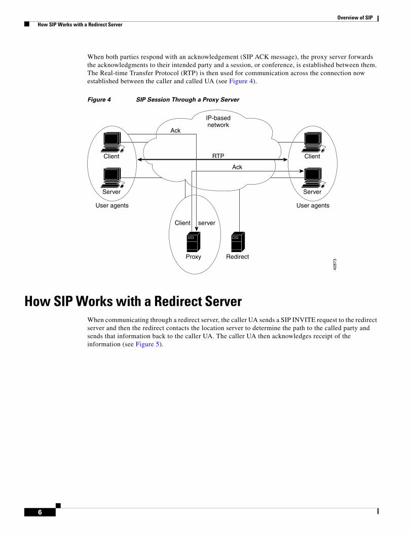
When both parties respond with an acknowledgement (SIP ACK message), the proxy server forwards the acknowledgments to their intended party and a session, or conference, is established between them. The Real-time Transfer Protocol (RTP) is then used for communication across the connection now established between the caller and called UA (see Figure 4).
Figure 4 SIP Session Through a Proxy Server
How SIP Works with a Redirect ServerWhen communicating through a redirect server, the caller UA sends a SIP INVITE request to the redirect server and then the redirect contacts the location server to determine the path to the called party and sends that information back to the caller UA. The caller UA then acknowledges receipt of the information (see Figure 5).
4287
3
User agents
Client
Server
User agents
Client
Server
IP-basednetwork
RTP
Ack
Ack
Proxy
Client server
Redirect

Overview of SIP How SIP Works with a Redirect Server
7
Figure 5 SIP INVITE Through a Redirect Server
The caller UA then sends a SIP INVITE request directly to the device indicated in the redirect information, bypassing the redirect server. (The target device at this stage could be either the called UA itself or a proxy server that will forward the request.) Once the request reaches the called UA, the called UA sends a response and, if it is a SIP 200 OK message, the caller UA responds with a SIP ACK message to acknowledge 200 OK response. A session is then established between the two endpoints using RTP for communication between the caller and called UAs (see Figure 6).
42
87
4
User agents
Client
Server
User agents
Client
Server
IP-basednetwork
302 Moved temporarilyInvite
Ack
Proxy Redirect

Overview of SIP SIP Call Flows
8
Figure 6 SIP Session Through a Redirect Server
SIP Call FlowsThis topic describes call flows for the following scenarios, which illustrate successful calls:
• SIP Gateway-to-SIP Gateway—Call Setup and Disconnect, page 8
• SIP Gateway-to-SIP Gateway—Call via SIP Redirect Server, page 12
• SIP Gateway-to-SIP Gateway—Call via SIP Proxy Server, page 16
SIP Gateway-to-SIP Gateway—Call Setup and DisconnectFigure 7 shows a successful gateway-to-gateway call setup and disconnect. The two end users are User A and User B. User A is located at PBX A, which is connected to SIP gateway 1 via a T1/E1. User B is located at PBX B, which is connected to SIP gateway 2 via a T1/E1. User B’s phone number is 555-0100. SIP gateway 1 is connected to SIP gateway 2 over an IP network.
The call flow scenario is as follows:
1. User A calls User B.
2. User B answers the call.
3. User B hangs up.
42
87
5
User agents
Client
Server
User agents
Client
Server
IP-basednetwork
200 OKInvite
Ack
Proxy
RTP
Redirect

Overview of SIP SIP Call Flows
9
Figure 7 SIP Gateway-to-SIP Gateway—Call Setup and Disconnect
Note RFC 2543-bis-04 requires that a UAS that receives a BYE request first send a response to any pending requests for that call before disconnecting. After receiving a BYE request, the UAS should respond with a 487 (Request Cancelled) status message.
The following processes occur in Figure 7.
3. Call Proceeding
9. Alerting
2-way RTP channel 2-way voice path2-way voice path
14. ACK
19. Disconnect
1-way voice path
12. Connect
1. Setup
PBX AUser A GW1 IP network GW2 PBX B User B
6. Call Proceeding
16. Disconnect
18. Release
7. Alerting
10. Connect
4. Setup
1-way voice path
15. Connect ACK
22. Release Complete
5. 100 Trying
8. 180 Ringing
2-way RTP channel
17. BYE
2. INVITE
11. 200 OK
21. 200 OK
13. Connect ACK
20. Release
23. Release Complete
2893
6
Overview of SIP SIP Call Flows
10
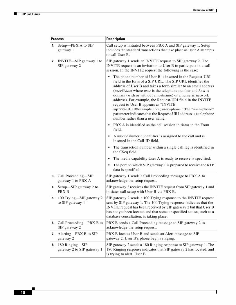
Process Description
1. Setup—PBX A to SIP gateway 1
Call setup is initiated between PBX A and SIP gateway 1. Setup includes the standard transactions that take place as User A attempts to call User B.
2. INVITE—SIP gateway 1 to SIP gateway 2
SIP gateway 1 sends an INVITE request to SIP gateway 2. The INVITE request is an invitation to User B to participate in a call session. In the INVITE request the following is the case:
• The phone number of User B is inserted in the Request-URI field in the form of a SIP URL. The SIP URL identifies the address of User B and takes a form similar to an email address (user@host where user is the telephone number and host is domain (with or without a hostname) or a numeric network address). For example, the Request-URI field in the INVITE request to User B appears as “INVITE sip:[email protected]; user=phone.” The “user=phone” parameter indicates that the Request-URI address is a telephone number rather than a user name.
• PBX A is identified as the call session initiator in the From field.
• A unique numeric identifier is assigned to the call and is inserted in the Call-ID field.
• The transaction number within a single call leg is identified in the CSeq field.
• The media capability User A is ready to receive is specified.
• The port on which SIP gateway 1 is prepared to receive the RTP data is specified.
3. Call Proceeding—SIP gateway 1 to PBX A
SIP gateway 1 sends a Call Proceeding message to PBX A to acknowledge the setup request.
4. Setup—SIP gateway 2 to PBX B
SIP gateway 2 receives the INVITE request from SIP gateway 1 and initiates call setup with User B via PBX B.
5. 100 Trying—SIP gateway 2 to SIP gateway 1
SIP gateway 2 sends a 100 Trying response to the INVITE request sent by SIP gateway 1. The 100 Trying response indicates that the INVITE request has been received by SIP gateway 2 but that User B has not yet been located and that some unspecified action, such as a database consultation, is taking place.
6. Call Proceeding—PBX B to SIP gateway 2
PBX B sends a Call Proceeding message to SIP gateway 2 to acknowledge the setup request.
7. Alerting—PBX B to SIP gateway 2
PBX B locates User B and sends an Alert message to SIP gateway 2. User B’s phone begins ringing.
8. 180 Ringing—SIP gateway 2 to SIP gateway 1
SIP gateway 2 sends a 180 Ringing response to SIP gateway 1. The 180 Ringing response indicates that SIP gateway 2 has located, and is trying to alert, User B.

Overview of SIP SIP Call Flows
11
9. Alerting—SIP gateway 1 to PBX A
SIP gateway 1 sends an Alert message to User A via PBX A. The Alert message indicates that SIP gateway 1 has received a 180 Ringing response from SIP gateway 2. User A hears the ringback tone that indicates that User B is being alerted.
At this point, a one-way voice path is established between SIP gateway 1 and PBX A and between SIP gateway 2 and PBX B. A two-way RTP channel is established between SIP gateway 1 and SIP gateway 2.
10. Connect—PBX B to SIP gateway 2
User B answers phone. PBX B sends a Connect message to SIP gateway 2. The Connect message notifies SIP gateway 2 that the connection has been made.
11. 200 OK—SIP gateway 2 to SIP gateway 1
SIP gateway 2 sends a 200 OK response to SIP gateway 1. The 200 OK response notifies SIP gateway 1 that the connection has been made.
If User B supports the media capability advertised in the INVITE message sent by SIP gateway 1, it advertises the intersection of its own and User A’s media capability in the 200 OK response. If User B does not support the media capability advertised by User A, it sends back a 400 Bad Request response with a 304 Warning header field.
12. Connect—SIP gateway 1 to PBX A
SIP gateway 1 sends a Connect message to PBX A. The Connect message notifies PBX A that the connection has been made.
13. Connect ACK—PBX A to SIP gateway 1
PBX A acknowledges SIP gateway 1’s Connect message.
14. ACK—SIP gateway 1 to SIP gateway 2
SIP gateway 1 sends an ACK to SIP gateway 2. The ACK confirms that SIP gateway 1 has received the 200 OK response from SIP gateway 2.
15. Connect ACK—SIP gateway 2 to PBX B
SIP gateway 2 acknowledges PBX B’s Connect message.
The call session is now active over a two-way voice path via Real-time Transport Protocol (RTP).
At this point, a two-way voice path is established between SIP gateway 1 and PBX A and between SIP gateway 2 and PBX B. A two-way RTP channel is established between SIP gateway 1 and SIP gateway 2.
16. Disconnect—PBX B to SIP gateway 2
Once User B hangs up, PBX B sends a Disconnect message to SIP gateway 2. The Disconnect message starts the call session termination process.
17. BYE—SIP gateway 2 to SIP gateway 1
SIP gateway 2 sends a BYE request to SIP gateway 1. The BYE request indicates that User B wants to release the call. Because it is User B that wants to terminate the call, the Request-URI field is now replaced with PBX A’s SIP URL and the From field contains User B’s SIP URL. The cseq value is incremented by one.
18. Release—SIP gateway 2 to PBX B
SIP gateway 2 sends a Release message to PBX B.
19. Disconnect—SIP gateway 1 to PBX A
SIP gateway 1 sends a Disconnect message to PBX A.
Process Description

Overview of SIP SIP Call Flows
12
SIP Gateway-to-SIP Gateway—Call via SIP Redirect ServerFigure 8 on page 13 shows a successful gateway-to-gateway call setup and disconnect via a SIP redirect server. In this scenario, the two end users are identified as User A and User B. User A is located at PBX A. PBX A is connected to SIP gateway 1 via a T1/E1. SIP gateway 1 is using a SIP redirect server. User B is located at PBX B. PBX B is connected to SIP gateway 2 via a T1/E1. User B’s phone number is 555-0100. SIP gateway 1 is connected to SIP gateway 2 over an IP network.
The call flow scenario is as follows:
1. User A calls User B through the SIP gateway 1 using a SIP redirect server.
2. User B answers the call.
3. User B hangs up.
20. Release—PBX A to SIP gateway 1
PBX A sends a Disconnect message to SIP gateway 1.
21. 200 OK—SIP gateway 1 to SIP gateway 2
SIP gateway 1 sends a 200 OK response to SIP gateway 2. The 200 OK response notifies SIP gateway 2 that SIP gateway 1 has received the BYE request.
22. Release Complete—PBX B to SIP gateway 2
PBX B sends a Release Complete message to SIP gateway 2.
23. Release Complete—SIP gateway 1 to PBX A
SIP gateway 1 sends a Release Complete message to PBX A and the session is terminated.
Process Description

Overview of SIP SIP Call Flows
13
Figure 8 SIP Gateway-to-SIP Gateway—Call via SIP Redirect Server
The following processes occur in Figure 8.
3. 300 MultipleChoice
12. Alerting
2-way RTP channel2-way voicepath
2-way voicepath
17. ACK
21.Disconnect
1-way VP
15. Connect
7. CallProceeding
1. Setup2. INVITE
4. ACK
PBX AUser A GW1 RS IP network GW2 PBX B User B
19. Disconnect
13. Connect
9. CallProceeding
10. Alerting
6. Setup
1-way VP
18. ConnectACK
22. Release
25. ReleaseComplete
8. 100 Trying
11. 180 Ringing
2-way RTP channel
20. BYE
5. INVITE
14. 200 OK
24. 200 OK
16. ConnectACK
26. ReleaseComplete
23. Release
2893
8
Overview of SIP SIP Call Flows
14
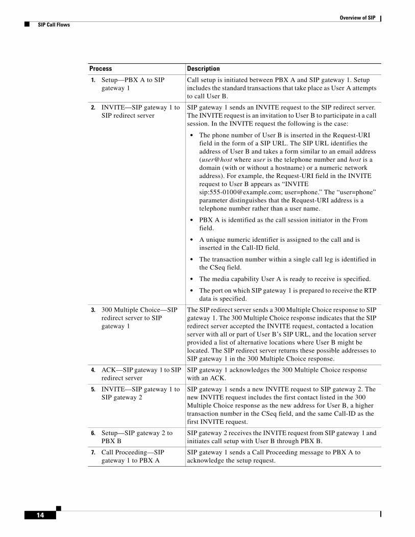
Process Description
1. Setup—PBX A to SIP gateway 1
Call setup is initiated between PBX A and SIP gateway 1. Setup includes the standard transactions that take place as User A attempts to call User B.
2. INVITE—SIP gateway 1 to SIP redirect server
SIP gateway 1 sends an INVITE request to the SIP redirect server. The INVITE request is an invitation to User B to participate in a call session. In the INVITE request the following is the case:
• The phone number of User B is inserted in the Request-URI field in the form of a SIP URL. The SIP URL identifies the address of User B and takes a form similar to an email address (user@host where user is the telephone number and host is a domain (with or without a hostname) or a numeric network address). For example, the Request-URI field in the INVITE request to User B appears as “INVITE sip:[email protected]; user=phone.” The “user=phone” parameter distinguishes that the Request-URI address is a telephone number rather than a user name.
• PBX A is identified as the call session initiator in the From field.
• A unique numeric identifier is assigned to the call and is inserted in the Call-ID field.
• The transaction number within a single call leg is identified in the CSeq field.
• The media capability User A is ready to receive is specified.
• The port on which SIP gateway 1 is prepared to receive the RTP data is specified.
3. 300 Multiple Choice—SIP redirect server to SIP gateway 1
The SIP redirect server sends a 300 Multiple Choice response to SIP gateway 1. The 300 Multiple Choice response indicates that the SIP redirect server accepted the INVITE request, contacted a location server with all or part of User B’s SIP URL, and the location server provided a list of alternative locations where User B might be located. The SIP redirect server returns these possible addresses to SIP gateway 1 in the 300 Multiple Choice response.
4. ACK—SIP gateway 1 to SIP redirect server
SIP gateway 1 acknowledges the 300 Multiple Choice response with an ACK.
5. INVITE—SIP gateway 1 to SIP gateway 2
SIP gateway 1 sends a new INVITE request to SIP gateway 2. The new INVITE request includes the first contact listed in the 300 Multiple Choice response as the new address for User B, a higher transaction number in the CSeq field, and the same Call-ID as the first INVITE request.
6. Setup—SIP gateway 2 to PBX B
SIP gateway 2 receives the INVITE request from SIP gateway 1 and initiates call setup with User B through PBX B.
7. Call Proceeding—SIP gateway 1 to PBX A
SIP gateway 1 sends a Call Proceeding message to PBX A to acknowledge the setup request.

Overview of SIP SIP Call Flows
15
8. 100 Trying—SIP gateway 2 to SIP gateway 1
SIP gateway 2 sends a 100 Trying response to the INVITE request sent by SIP gateway 1. The 100 Trying response indicates that the INVITE request has been received by SIP gateway 2 but that User B has not yet been located.
9. Call Proceeding—PBX B to SIP gateway 2
PBX B sends a Call Proceeding message to SIP gateway 2 to acknowledge the setup request.
10. Alerting—PBX B to SIP gateway 2
PBX B locates User B and sends an Alert message to SIP gateway 2. User B’s phone begins to ring.
11. 180 Ringing—SIP gateway 2 to SIP gateway 1
SIP gateway 2 sends a 180 Ringing response to SIP gateway 1. The 180 Ringing response indicates that SIP gateway 2 has located, and is trying to alert, User B.
12. Alerting—SIP gateway 1 to PBX A
SIP gateway 1 sends an Alert message to PBX A. User A hears ringback tone.
At this point, a one-way voice path is established between SIP gateway 1 and PBXA and between SIP gateway 2 and PBX B. A two-way RTP channel is established between SIP gateway 1 and SIP gateway 2.
13. Connect—PBX B to SIP gateway 2
User B answers phone. PBX B sends a Connect message to SIP gateway 2. The Connect message notifies SIP gateway 2 that the connection has been made.
14. 200 OK—SIP gateway 2 to SIP gateway 1
SIP gateway 2 sends a 200 OK response to SIP gateway 1. The 200 OK response notifies SIP gateway 1 that the connection has been made.
If User B supports the media capability advertised in the INVITE message sent by SIP gateway 1, it advertises the intersection of its own and User A’s media capability in the 200 OK response. If User B does not support the media capability advertised by User A, it sends back a 400 Bad Request response with a 304 Warning header field.
15. Connect—SIP gateway 1 to PBX A
SIP gateway 1 sends a Connect message to PBX A. The Connect message notifies PBX A that the connection has been made.
16. Connect ACK—PBX A to SIP gateway 1
PBX A acknowledges SIP gateway 1’s Connect message.
17. ACK—SIP gateway 1 to SIP gateway 2
SIP gateway 1 sends an ACK to SIP gateway 2. The ACK confirms that the 200 OK response has been received.
The call is now in progress over a two-way voice path via RTP.
18. Connect ACK—SIP gateway 2 to PBX B
SIP gateway 2 acknowledges PBX B’s Connect message.
At this point, a two-way voice path is established between SIP gateway 1 and PBX A and between SIP gateway 2 and PBX B. A two-way RTP channel is established between SIP gateway 1 and SIP gateway 2.
19. Disconnect—PBX B to SIP gateway 2
Once User B hangs up, PBX B sends a Disconnect message to SIP gateway 2. The Disconnect message starts the call session termination process.
Process Description

Overview of SIP SIP Call Flows
16
SIP Gateway-to-SIP Gateway—Call via SIP Proxy ServerFigure 9 and Figure 10 show a successful gateway-to-gateway call setup and disconnect via a proxy server. The two end users are User A and User B. User A is located at PBX A, which is connected to SIP gateway 1 via a T1/E1. SIP gateway 1 is using a proxy server. SIP gateway 1 is connected to SIP gateway 2 over an IP network. User B is located at PBX B, which is connected to SIP gateway 2 (a SIP gateway) via a T1/E1. User B’s phone number is 555-0100.
Note The Record-Route header field is inserted by proxies in a request to force future requests in the dialog to be routed through the proxy.
20. BYE—SIP gateway 2 to SIP gateway 1
SIP gateway 2 sends a BYE request to SIP gateway 1. The BYE request indicates that User B wants to release the call. Because it is User B that wants to terminate the call, the Request-URI field is now replaced with PBX A’s SIP URL and the From field contains User B’s SIP URL.
21. Disconnect—SIP gateway 1 to PBX A
SIP gateway 1 sends a Disconnect message to PBX A.
22. Release—SIP gateway 2 to PBX B
SIP gateway 2 sends a Release message to PBX B.
23. Release—PBX A to SIP gateway 1
PBX A sends a Release message to SIP gateway 1.
24. 200 OK—SIP gateway 1 to SIP gateway 2
SIP gateway 1 sends a 200 OK response to SIP gateway 2. The 200 OK response notifies SIP gateway 2 that SIP gateway 1 has received the BYE request.
25. Release Complete—PBX B to SIP gateway 2
PBX B sends a Release Complete message to SIP gateway 2.
26. Release Complete—SIP gateway 1 to PBX A
SIP gateway 1 sends a Release Complete message to PBX A and the session is terminated.
Process Description

Overview of SIP SIP Call Flows
17
In Figure 9, the record route feature is enabled on the proxy server. In Figure 10, record route is disabled on the proxy server.
When record route is enabled, the proxy server adds the Record-Route header to the SIP messages to ensure that it is in the path of subsequent SIP requests for the same call leg. The Record-Route field contains a globally reachable Request-URI that identifies the proxy server. When record route is enabled, each proxy server adds its Request-URI to the beginning of the list.
When record route is disabled, SIP messages flow directly through the SIP gateways once a call has been established.
The call flow is as follows:
1. User A calls User B via SIP gateway 1 using a proxy server.
2. User B answers the call.
3. User B hangs up.
Figure 9 SIP Gateway-to-SIP Gateway—Call via SIP Proxy Server with Record Route Enabled
2-way RTP channel
11. 180 Ringing
5. 100 Trying
15. 200 OK
1-way voicepath
7. 100 Trying
10. 180 Ringing
14. 200 OK
22. BYE
12. Alerting
2-way RTP channel
16. Connect
24.Disconnect
3. CallProceeding
1. Setup
17. ConnectACK
1-way voicepath
2-way voicepath
2-way voicepath
8. CallProceeding
9. Alerting
21. Disconnect
29. ReleaseComplete
13. Connect
6. Setup
25.Release
20. ConnectACK
2. INVITE
18. ACK
27. 200 OK
PBX AUser A GW1Proxyserver IP network GW2 PBX B User B
23. BYE
4. INVITE
19. ACK
28. 200 OK30. ReleaseComplete
26. Release
2894
2

Overview of SIP SIP Call Flows
18
The following processes occur in Figure 9.
Process Description
1. Setup—PBX A to SIP gateway 1
Call setup is initiated between PBX A and SIP gateway 1. Setup includes the standard transactions that take place as User A attempts to call User B.
2. INVITE—SIP gateway 1 to proxy server
SIP gateway 1 sends an INVITE request to the SIP proxy server. The INVITE request is an invitation to User B to participate in a call session.
In the INVITE request:
• The phone number of User B is inserted in the Request-URI field in the form of a SIP URL. The SIP URL identifies the address of User B and takes a form similar to an email address (user@host where user is the telephone number and host is a domain (with or without a hostname) or a numeric network address). For example, the Request-URI field in the INVITE request to User B appears as “INVITE sip:[email protected]; user=phone.” The “user=phone” parameter distinguishes that the Request-URI address is a telephone number rather than a user name.
• PBX A is identified as the call session initiator in the From field.
• A unique numeric identifier is assigned to the call and is inserted in the Call-ID field.
• The transaction number within a single call leg is identified in the CSeq field.
• The media capability User A is ready to receive is specified.
• The port on which SIP gateway 1 is prepared to receive the RTP data is specified.
3. Call Proceeding—SIP gateway 1 to PBX A
SIP gateway 1 sends a Call Proceeding message to PBX A to acknowledge the setup request.
4. INVITE—SIP proxy server to SIP gateway 2
The SIP proxy server checks whether its own address is contained in the Via field (to prevent loops), directly copies the To, From, Call-ID, and Contact fields from the request it received from SIP gateway 1, changes the Request-URI to indicate the server to which it intends to send the INVITE request, and then sends a new INVITE request to SIP gateway 2.
5. 100 Trying—SIP proxy server to SIP gateway 1
The SIP proxy server sends a 100 Trying response to SIP gateway 1.
6. Setup—SIP gateway 2 to PBX B
SIP gateway 2 receives the INVITE request from the SIP proxy server and initiates call setup with User B via PBX B.
7. 100 Trying—SIP gateway 2 to SIP proxy server
SIP gateway 2 sends a 100 Trying response to the SIP proxy server. The SIP proxy server might or might not forward the 100 Trying response to SIP gateway 1.
8. Call Proceeding—PBX B to SIP gateway 2
PBX B sends a Call Proceeding message to SIP gateway 2 to acknowledge the setup request.

Overview of SIP SIP Call Flows
19
9. Alerting—PBX B to SIP gateway 2
PBX B locates User B and sends an Alert message to SIP gateway 2. User B’s phone begins to ring.
10. 180 Ringing—SIP gateway 2 to SIP proxy server
SIP gateway 2 sends a 180 Ringing response to the SIP proxy server.
11. 180 Ringing—SIP proxy server to SIP gateway 1
The SIP proxy server forwards the 180 Ringing response to SIP gateway 1.
12. Alerting—SIP gateway 1 to PBX A
SIP gateway 1 sends an Alert message to User A via PBX A. The Alert message indicates that SIP gateway 1 has received a 180 Ringing response. User A hears the ringback tone that indicates that User B is being alerted.
At this point, a one-way voice path is established between SIP gateway 1 and PBX A and between SIP gateway 2 and PBX B. A two-way RTP channel is established between SIP gateway 1 and SIP gateway 2.
13. Connect—PBX B to SIP gateway 2
User B answers the phone. PBX B sends a Connect message to SIP gateway 2. The connect message notifies SIP gateway 2 that the connection has been made.
14. 200 OK—SIP gateway 2 to SIP proxy server
SIP gateway 2 sends a 200 OK response (including the Record-Route header received in the INVITE) to the SIP proxy server. The 200 OK response notifies the SIP proxy server that the connection has been made.
If User B supports the media capability advertised in the INVITE message sent by the SIP proxy server, it advertises the intersection of its own and User A’s media capability in the 200 OK response. If User B does not support the media capability advertised by User A, it sends back a 400 Bad Request response with a 304 Warning header field.
The SIP proxy server must forward 200 OK responses upstream.
15. 200 OK—SIP proxy server to SIP gateway 1
The SIP proxy server forwards the 200 OK response that it received from SIP gateway 2 to SIP gateway 1. In the 200 OK response, the SIP proxy server forwards the Record-Route header to ensure that it is in the path of subsequent SIP requests for the same call leg. In the Record-Route field, the SIP proxy server adds its Request-URI.
16. Connect—SIP gateway 1 to PBX A
SIP gateway 1 sends a Connect message to PBX A. The Connect message notifies PBX A that the connection has been made.
17. Connect ACK—PBX A to SIP gateway 1
PBX A acknowledges SIP gateway 1’s Connect message.
18. ACK—SIP gateway 1 to SIP proxy server
SIP gateway 1 sends an ACK to the SIP proxy server. The ACK confirms that SIP gateway 1 has received the 200 OK response from the SIP proxy server.
Process Description
Overview of SIP SIP Call Flows
20
19. ACK—SIP proxy server to SIP gateway 2
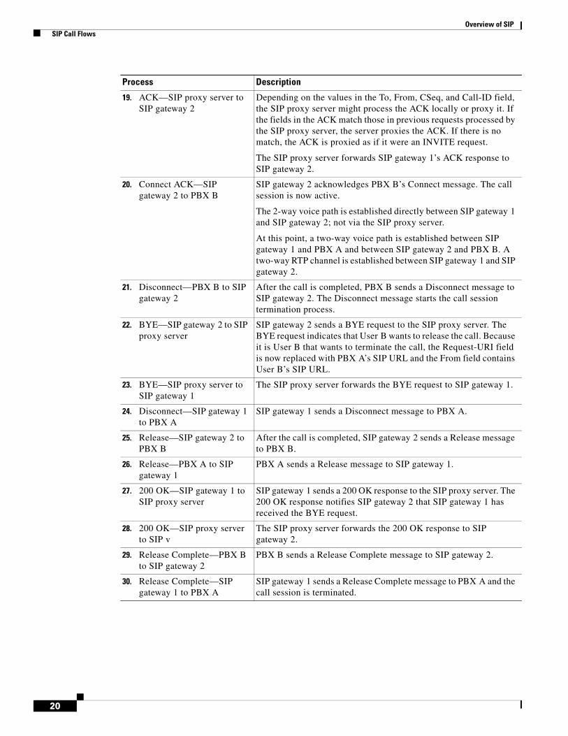
Depending on the values in the To, From, CSeq, and Call-ID field, the SIP proxy server might process the ACK locally or proxy it. If the fields in the ACK match those in previous requests processed by the SIP proxy server, the server proxies the ACK. If there is no match, the ACK is proxied as if it were an INVITE request.
The SIP proxy server forwards SIP gateway 1’s ACK response to SIP gateway 2.
20. Connect ACK—SIP gateway 2 to PBX B
SIP gateway 2 acknowledges PBX B’s Connect message. The call session is now active.
The 2-way voice path is established directly between SIP gateway 1 and SIP gateway 2; not via the SIP proxy server.
At this point, a two-way voice path is established between SIP gateway 1 and PBX A and between SIP gateway 2 and PBX B. A two-way RTP channel is established between SIP gateway 1 and SIP gateway 2.
21. Disconnect—PBX B to SIP gateway 2
After the call is completed, PBX B sends a Disconnect message to SIP gateway 2. The Disconnect message starts the call session termination process.
22. BYE—SIP gateway 2 to SIP proxy server
SIP gateway 2 sends a BYE request to the SIP proxy server. The BYE request indicates that User B wants to release the call. Because it is User B that wants to terminate the call, the Request-URI field is now replaced with PBX A’s SIP URL and the From field contains User B’s SIP URL.
23. BYE—SIP proxy server to SIP gateway 1
The SIP proxy server forwards the BYE request to SIP gateway 1.
24. Disconnect—SIP gateway 1 to PBX A
SIP gateway 1 sends a Disconnect message to PBX A.
25. Release—SIP gateway 2 to PBX B
After the call is completed, SIP gateway 2 sends a Release message to PBX B.
26. Release—PBX A to SIP gateway 1
PBX A sends a Release message to SIP gateway 1.
27. 200 OK—SIP gateway 1 to SIP proxy server
SIP gateway 1 sends a 200 OK response to the SIP proxy server. The 200 OK response notifies SIP gateway 2 that SIP gateway 1 has received the BYE request.
28. 200 OK—SIP proxy server to SIP v
The SIP proxy server forwards the 200 OK response to SIP gateway 2.
29. Release Complete—PBX B to SIP gateway 2
PBX B sends a Release Complete message to SIP gateway 2.
30. Release Complete—SIP gateway 1 to PBX A
SIP gateway 1 sends a Release Complete message to PBX A and the call session is terminated.
Process Description

Overview of SIP SIP Call Flows
21
Figure 10 SIP Gateway-to-SIP Gateway—Call via a Proxy Server with Record Route Disabled
The following processes occur in Figure 10.
3. Call Proceeding
12. Alerting
22. Disconnect
16. Connect
17. Connect ACK
6. Setup
23. Release
19. ConnectACK
8. CallProceeding
26. ReleaseComplete27. Release
Complete
9. Alerting
13. Connect
20. Disconnect
1. Setup
24. Release
PBX A PBX BUser A User BGW1
Proxyserver GW2IP network
5. 100 Trying
15. 200 OK
18. ACK
21. BYE
10. 180 Ringing
7. 100 Trying
14. 200 OK
11. 180 Ringing
2. INVITE
2-way voice path
2-way RTP channel
2-way RTP channel
1-way voice path1-way voicepath
2-way voicepath
4. INVITE
25. 200 OK
3270
7

Overview of SIP SIP Call Flows
22
Process Description
1. Setup—PBX A to SIP gateway 1
Call setup is initiated between PBX A and SIP gateway 1. Setup includes the standard transactions that take place as User A attempts to call User B.
2. INVITE—SIP gateway 1 to SIP proxy server
SIP gateway 1 sends an INVITE request to the SIP proxy server. The INVITE request is an invitation to User B to participate in a call session. In the INVITE request the following is the case:
• The phone number of User B is inserted in the Request-URI field in the form of a SIP URL. The SIP URL identifies the address of User B and takes a form similar to an email address (user@host where user is the telephone number and host is a domain (with or without a hostname) or a numeric network address). For example, the Request-URI field in the INVITE request to User B appears as “INVITE sip:[email protected]; user=phone.” The “user=phone” parameter distinguishes that the Request-URI address is a telephone number rather than a user name.
• PBX A is identified as the call session initiator in the From field.
• A unique numeric identifier is assigned to the call and is inserted in the Call-ID field.
• The transaction number within a single call leg is identified in the CSeq field.
• The media capability User A is ready to receive is specified.
• The port on which SIP gateway 1 is prepared to receive the RTP data is specified.
3. Call Proceeding—SIP gateway 1 to PBX A
SIP gateway 1 sends a Call Proceeding message to PBX A to acknowledge the setup request.
4. INVITE—SIP proxy server to SIP gateway 2
The SIP proxy server checks whether its own address is contained in the Via field (to prevent loops), directly copies the To, From, Call-ID, and Contact fields from the request it received from SIP gateway 1, changes the Request-URI to indicate the server to which it intends to send the INVITE request, and then sends a new INVITE request to SIP gateway 2.
5. 100 Trying—SIP proxy server to SIP gateway 1
The SIP proxy server sends a 100 Trying response to SIP gateway 1.
6. Setup—SIP gateway 2 to PBX B
SIP gateway 2 receives the INVITE request from the SIP proxy server and initiates call setup with User B via PBX B.
7. 100 Trying—SIP gateway 2 to SIP proxy server
SIP gateway 2 sends a 100 Trying response to the SIP proxy server. The SIP proxy server might or might not forward the 100 Trying response to SIP gateway 1.
8. Call Proceeding—PBX B to SIP gateway 2
PBX B sends a Call Proceeding message to SIP gateway 2 to acknowledge setup request.
9. Alerting—PBX B to SIP gateway 2
PBX B locates User B and sends an Alert message to SIP gateway 2. User B’s phone begins to ring.
Overview of SIP SIP Call Flows
23
10. 180 Ringing—SIP gateway 2 to SIP proxy server
SIP gateway 2 sends a 180 Ringing response to the SIP proxy server.
11. 180 Ringing—SIP proxy server to SIP gateway 1
The SIP proxy server forwards the 180 Ringing response to SIP gateway 1.
12. Alerting—SIP gateway 1 to PBX A
SIP gateway 1 sends an Alert message to User A via PBX A. The Alert message indicates that SIP gateway 1 has received a 180 Ringing response. User A hears the ringback tone that indicates that User B is being alerted.
At this point, a one-way voice path is established between SIP gateway 1 and PBX A and between SIP gateway 2 and PBX B. A two-way RTP channel is established between SIP gateway 1 and SIP gateway 2.
13. Connect—PBX B to SIP gateway 2
User B answers the phone. PBX B sends a Connect message to SIP gateway 2. The connect message notifies SIP gateway 2 that the connection has been made.
14. 200 OK—SIP gateway 2 to SIP proxy server
SIP gateway 2 sends a 200 OK response to the SIP proxy server. The 200 OK response notifies the SIP proxy server that the connection has been made.
If User B supports the media capability advertised in the INVITE message sent by the SIP proxy server, it advertises the intersection of its own and User A’s media capability in the 200 OK response. If User B does not support the media capability advertised by User A, it sends back a 400 Bad Request response with a 304 Warning header field.
The SIP proxy server must forward 200 OK responses upstream.
15. 200 OK—SIP proxy server to SIP gateway 1
The SIP proxy server forwards the 200 OK response that it received from SIP gateway 2 to SIP gateway 1.
16. Connect—SIP gateway 1 to PBX A
SIP gateway 1 sends a Connect message to PBX A. The Connect message notifies PBX A that the connection has been made.
17. Connect ACK—PBX A to SIP gateway 1
PBX A acknowledges SIP gateway 1’s Connect message.
18. ACK—SIP gateway 1 to SIP gateway 2
SIP gateway 1 sends an ACK to SIP gateway 2. The ACK confirms that SIP gateway 1 has received the 200 OK response from the SIP proxy server.
19. Connect ACK—SIP gateway 2 to PBX B
SIP gateway 2 acknowledges PBX B’s Connect message. The call session is now active.
The 2-way voice path is established directly between SIP gateway 1 and SIP gateway 2; not via the SIP proxy server.
At this point, a two-way voice path is established between SIP gateway 1 and PBX A and between SIP gateway 2 and PBX B. A two-way RTP channel is established between SIP gateway 1 and SIP gateway 2.
Process Description

Overview of SIP Additional References
24
Additional ReferencesThe following sections provide references related to SIP.
Note • In addition to the references listed below, each chapter provides additional references related to SIP.
• Some of the products and services mentioned in this guide may have reached end of life, end of sale, or both. Details are available at http://www.cisco.com/en/US/products/prod_end_of_life.html.
20. Disconnect—PBX B to SIP gateway 2
After the call is completed, PBX B sends a Disconnect message to SIP gateway 2. The Disconnect message starts the call session termination process.
21. BYE—SIP gateway 2 to SIP gateway 1
SIP gateway 2 sends a BYE request to SIP gateway 1. The BYE request indicates that User B wants to release the call. Because it is User B that wants to terminate the call, the Request-URI field is now replaced with PBX A’s SIP URL and the From field contains User B’s SIP URL.
22. Disconnect—SIP gateway 1 to PBX A
SIP gateway 1 sends a Disconnect message to PBX A.
23. Release—SIP gateway 2 to PBX B
After the call is completed, SIP gateway 2 sends a Release message to PBX B.
24. Release—PBX A to SIP gateway 1
PBX A sends a Release message to SIP gateway 1.
25. 200 OK—SIP gateway 1 to SIP gateway 2
SIP gateway 1 sends a 200 OK response to SIP gateway 2. The 200 OK response notifies SIP gateway 2 that SIP gateway 1 has received the BYE request.
26. Release Complete—PBX B to SIP gateway 2
PBX B sends a Release Complete message to SIP gateway 2.
27. Release Complete—SIP gateway 1 to PBX A
SIP gateway 1 sends a Release Complete message to PBX A and the call session is terminated.
Process Description

Overview of SIP Additional References
25
Related Documents
Related Topic Document Title
Basic router configuration • Cisco 2600 series documentation at http://www.cisco.com/univercd/cc/td/doc/product/access/acs_mod/cis2600/index.htm
• Cisco 3600 series documentation at http://www.cisco.com/univercd/cc/td/doc/product/access/acs_mod/cis3600/index.htm
• Cisco 3700 series documentation at http://www.cisco.com/univercd/cc/td/doc/product/access/acs_mod/cis3700/index.htm
• Cisco AS5300 documentation at http://www.cisco.com/univercd/cc/td/doc/product/access/acs_serv/5300/index.htm
Cisco IOS command references • Cisco IOS Debug Command Reference, Release 12.3T at http://www.cisco.com/univercd/cc/td/doc/product/software/ios123/123tcr/123dbr/index.htm
• Cisco IOS Voice Command Reference, Release 12.3T at http://www.cisco.com/univercd/cc/td/doc/product/software/ios123/123tcr/123tvr/index.htm
Cisco IOS configuration fundamentals and examples
• Cisco IOS Configuration Fundamentals Configuration Guide at http://www.cisco.com/univercd/cc/td/doc/product/software/ios122/122cgcr/ffun_c/
• Cisco IOS Interface Command Reference at http://www.cisco.com/univercd/cc/td/doc/product/software/ios122/122cgcr/finter_r/index.htm
• Cisco IOS Interface Configuration Guide at http://www.cisco.com/univercd/cc/td/doc/product/software/ios122/122cgcr/finter_c/
• Cisco IOS Voice, Video, and Fax Configuration Guide, Release 12.2 at http://www.cisco.com/univercd/cc/td/doc/product/software/ios122/122cgcr/fvvfax_c/index.htm
• Cisco Systems Technologies website at http://cisco.com/en/US/tech/index.html
From the website, select a technology category and subsequent hierarchy of subcategories, then click Technical Documentation > Configuration Examples.
Cisco IOS Voice Configuration Library, including library preface and glossary
• Cisco IOS Voice Configuration Library at http://www.cisco.com/en/US/docs/ios/12_3/vvf_c/cisco_ios_voice_configuration_library_glossary/vcl.htm
Developer support • Developer Support Agreement at http://www.cisco.com/go/developersupport
IVR script information • TCL IVR API 2.0 Programming Guide at http://www.cisco.com/univercd/cc/td/doc/product/access/acs_serv/vapp_dev/tclivrv2/index.htm
NAT configuration • Configuring Network Address Translation: Getting Started at http://www.cisco.com/warp/public/556/12.htm

Overview of SIP Additional References
26
SIP documents • Cisco SIP proxy server documents at http://www.cisco.com/univercd/cc/td/doc/product/voice/sipproxy/index.htm
• Guide to Cisco Systems' VoIP Infrastructure Solution for SIP at http://www.cisco.com/univercd/cc/td/doc/product/voice/sipsols/biggulp/index.htm
• Session Initiation Protocol Gateway Call Flows at http://www.cisco.com/univercd/cc/td/doc/product/software/ios122/rel_docs/sip_flo/index.htm
SS7 for voice gateways • Configuring Media Gateways for the SS7 Interconnect for Voice Gateways Solution at http://www.cisco.com/univercd/cc/td/doc/product/access/sc/rel7/soln/das22/gateway/dascfg5.htm
Tcl IVR programming • Tcl IVR API Version 2.0 Programmer's Guide at http://www.cisco.com/univercd/cc/td/doc/product/access/acs_serv/vapp_dev/tclivrv2/index.htm
Troubleshooting • Cisco IOS Debug Command Reference, Release 12.3T at http://www.cisco.com/univercd/cc/td/doc/product/software/ios123/123tcr/123dbr/index.htm
• Cisco IOS Voice Troubleshooting and Monitoring Guide at http://www.cisco.com/univercd/cc/td/doc/product/software/ios123/123cgcr/vvfax_c/voipt_c/index.htm
• Internetwork Troubleshooting Guide at http://www.cisco.com/univercd/cc/td/doc/cisintwk/itg_v1/index.htm
• Troubleshooting and Debugging VoIP Call Basics at http://www.cisco.com/warp/public/788/voip/voip_debugcalls.html
• Voice over IP Troubleshooting and Monitoring at http://cisco.com/univercd/cc/td/doc/product/software/ios123/123cgcr/vvfax_c/voipt_c/index.htm
• VoIP Debug Commands at http://www.cisco.com/univercd/cc/td/doc/product/access/acs_mod/1700/1750/1750voip/debug.htm
VoATM configuration • Configuring AAL2 and AAL5 for the High-Performance Advanced Integration Module on the Cisco 2600 Series at http://www.cisco.com/univercd/cc/td/doc/product/software/ios122/122newft/122limit/122x/122xa/122xa_2/ft_ataim.htm
VoIP configuration • Voice over IP for the Cisco 2600/3600 Series at http://www.cisco.com/univercd/cc/td/doc/product/access/nubuvoip/voip3600/index.htm
• Voice over IP for the Cisco AS5300 at http://www.cisco.com/univercd/cc/td/doc/product/access/nubuvoip/voip5300/index.htm
• Voice over IP for the Cisco AS5800 at http://www.cisco.com/univercd/cc/td/doc/product/access/nubuvoip/voip5800/index.htm
VSA information • RADIUS Vendor-Specific Attributes Voice Implementation Guide at http://www.cisco.com/univercd/cc/td/doc/product/access/acs_serv/vapp_dev/vsaig3.htm
Related Topic Document Title

Overview of SIP Additional References
27
WAN configuration • Cisco IOS Wide-Area Networking Command Reference at http://www.cisco.com/univercd/cc/td/doc/product/software/ios122/122cgcr/fwan_r/index.htm
• Cisco IOS Wide-Area Networking Configuration Guide at http://www.cisco.com/univercd/cc/td/doc/product/software/ios122/122cgcr/fwan_c/wcfatm.htm
Other documents Cisco Internetworking Terms and Acronyms at http://www.cisco.com/univercd/cc/td/doc/cisintwk/ita/
Cisco Resource Policy Management System 2.0 at http://www.cisco.com/univercd/cc/td/doc/product/access/acs_soft/rpms/rpms_2-0/
VoIP Call Admission Control at http://www.cisco.com/univercd/cc/td/doc/cisintwk/intsolns/voipsol/cac.htm
Related Topic Document Title
Overview of SIP Additional References
28
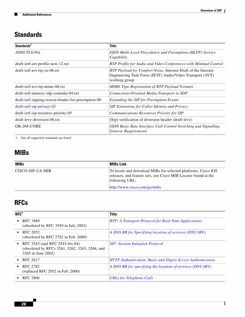
Standards
MIBs
RFCs
Standards1
1. Not all supported standards are listed.
Title
ANSI TI.619/a ISDN Multi-Level Precedence and Preemption (MLPP) Service Capability
draft-ietf-avt-profile-new-12.txt RTP Profile for Audio and Video Conferences with Minimal Control
draft-ietf-avt-rtp-cn-06.txt RTP Payload for Comfort Noise, Internet Draft of the Internet Engineering Task Force (IETF) Audio/Video Transport (AVT) working group
draft-ietf-avt-rtp-mime-06.txt MIME Type Registration of RTP Payload Formats
draft-ietf-mmusic-sdp-comedia-04.txt Connection-Oriented Media Transport in SDP
draft-ietf-sipping-reason-header-for-preemption-00 Extending the SIP for Preemption Events
draft-ietf-sip-privacy-02 SIP Extensions for Caller Identity and Privacy
draft-ietf-sip-resource-priority-05 Communications Resources Priority for SIP
draft-levy-diversion-06.txt [Sip] verification of diversion header (draft-levy)
GR-268-CORE ISDN Basic Rate Interface Call Control Switching and Signalling Generic Requirements
MIBs MIBs Link
CISCO-SIP-UA-MIB To locate and download MIBs for selected platforms, Cisco IOS releases, and feature sets, use Cisco MIB Locator found at the following URL:
http://www.cisco.com/go/mibs
RFC1 Title
• RFC 1889(obsoleted by RFC 3550 in July 2003)
RTP: A Transport Protocol for Real-Time Applications
• RFC 2052(obsoleted by RFC 2782 in Feb. 2000)
A DNS RR for Specifying location of services (DNS SRV)
• RFC 2543 (and RFC 2543-bis-04)(obsoleted by RFCs 3261, 3262, 3263, 3264, and 3265 in June 2002)
SIP: Session Initiation Protocol
• RFC 2617 HTTP Authentication: Basic and Digest Access Authentication
• RFC 2782(replaced RFC 2052 in Feb. 2000)
A DNS RR for specifying the location of services (DNS SRV)
• RFC 2806 URLs for Telephone Calls

Overview of SIP Additional References
29
• RFC 2833(obsoleted by RFCs 4733 and 4734 in Dec. 2006)
RTP Payload for DTMF Digits, Telephony Tones and Telephony Signals
• RFC 2976 SIP INFO Method
• RFC 3261(replaced RFC 2543 in June 2002 and updated by RFCs 3853 (July 2004) and 4320 (Jan. 2006))
SIP: Session Initiation Protocol
• RFC 3262(replaced RFC 2543 in June 2002)
Reliability of Provisional Responses in Session Initiation Protocol (SIP)
• RFC 3263(replaced RFC 2543 in June 2002)
Session Initiation Protocol (SIP): Locating SIP Servers
• RFC 3264(replaced RFC 2543 in June 2002)
An Offer/Answer Model with Session Description Protocol (SDP)
• RFC 3265(replaced RFC 2543 in June 2002)
Session Initiation Protocol (SIP)-Specific Event Notification
• RFC 3311 The Session Initiation Protocol (SIP) UPDATE Method
• RFC 3312(updated by RFC 4032 in March 2005)
Integration of Resource Management and Session Initiation Protocol (SIP)
• RFC 3326 The Reason Header Field for the Session Initiation Protocol
• RFC 3420 Internet Media Type message/sipfrag
• RFC 3515 The Session Initiation Protocol (SIP) Refer Method
• RFC 3550(replaced RFC 1889 in July 2003)
RTP: A Transport Protocol for Real-Time Applications
• RFC 3853(updated RFC 3261 in July 2004)
S/MIME Advanced Encryption Standard (AES) Requirement for the Session Initiation Protocol (SIP)
• RFC 4032(updated RFC 3312 in March 2005)
Update to the Session Initiation Protocol (SIP) Preconditions Framework
• RFC 4320(updated RFC 3261 in July 2004)
Actions Addressing Identified Issues with the Session Initiation Protocol's (SIP) Non-INVITE Transaction
• RFC 4733(replaced RFC 2833 andwas updated by RFC 4734 in Dec. 2006)
RTP Payload for DTMF Digits, Telephony Tones, and Telephony Signals
• RFC 4734(replaced RFC 2833 and updated RFC 4733in Dec. 2006)
Definition of Events for Modem, Fax, and Text Telephony Signals
1. Not all supported RFCs are listed.
RFC1 Title
Overview of SIP Additional References
30
Technical Assistance
Any Internet Protocol (IP) addresses used in this document are not intended to be actual addresses. Any examples, command display output, and figures included in the document are shown for illustrative purposes only. Any use of actual IP addresses in illustrative content is unintentional and coincidental.
© 2007 Cisco Systems, Inc. All rights reserved.
Description Link
The Cisco Technical Support website contains thousands of pages of searchable technical content, including links to products, technologies, solutions, technical tips, and tools. Registered Cisco.com users can log in from this page to access even more content.
http://www.cisco.com/techsupport
CCVP, the Cisco logo, and Welcome to the Human Network are trademarks of Cisco Systems, Inc.; Changing the Way We Work, Live, Play, and Learn isa service mark of Cisco Systems, Inc.; and Access Registrar, Aironet, Catalyst, CCDA, CCDP, CCIE, CCIP, CCNA, CCNP, CCSP, Cisco, the CiscoCertified Internetwork Expert logo, Cisco IOS, Cisco Press, Cisco Systems, Cisco Systems Capital, the Cisco Systems logo, Cisco Unity,Enterprise/Solver, EtherChannel, EtherFast, EtherSwitch, Fast Step, Follow Me Browsing, FormShare, GigaDrive, HomeLink, Internet Quotient, IOS,iPhone, IP/TV, iQ Expertise, the iQ logo, iQ Net Readiness Scorecard, iQuick Study, LightStream, Linksys, MeetingPlace, MGX, Networkers,Networking Academy, Network Registrar, PIX, ProConnect, ScriptShare, SMARTnet, StackWise, The Fastest Way to Increase Your Internet Quotient,and TransPath are registered trademarks of Cisco Systems, Inc. and/or its affiliates in the United States and certain other countries.
All other trademarks mentioned in this document or Website are the property of their respective owners. The use of the word partner does not imply apartnership relationship between Cisco and any other company. (0711R)