overview of section iii, division 5
TRANSCRIPT
Overview of Section III, Division 5
Advisory Committee for Reactor Safeguards
July 20, 2021
Jeff Poehler, Sr. Materials Engineer
Reactor Engineering BranchOffice of Nuclear Regulatory Research
1
ASME Section III, Rules for
Construction of Nuclear Facility
Components -Division 5, High
Temperature Reactors
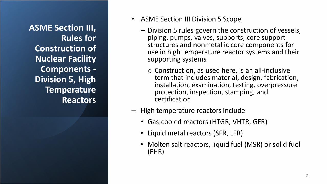
• ASME Section III Division 5 Scope– Division 5 rules govern the construction of vessels,
piping, pumps, valves, supports, core support structures and nonmetallic core components for use in high temperature reactor systems and their supporting systemso Construction, as used here, is an all-inclusive
term that includes material, design, fabrication, installation, examination, testing, overpressure protection, inspection, stamping, and certification
– High temperature reactors include• Gas-cooled reactors (HTGR, VHTR, GFR)• Liquid metal reactors (SFR, LFR)• Molten salt reactors, liquid fuel (MSR) or solid fuel
(FHR)
2
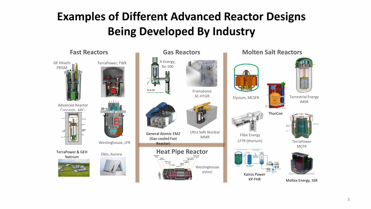
Examples of Different Advanced Reactor Designs Being Developed By Industry
Terrestrial EnergyIMSR
Fast Reactors Molten Salt Reactors
Elysium, MCSFR
TerraPowerMCFR
Gas Reactors
Flibe EnergyLFTR (thorium)
X-Energy, Xe-100
FramatomeSC-HTGR
General Atomic EM2(Gas-cooled Fast
Reactor)
Ultra Safe NuclearMMR
WestinghouseeVinci
Heat Pipe Reactor
GE HitachiPRISM
TerraPower, TWR
Advanced Reactor Concepts, ARC-
100
Westinghouse, LFR
Oklo, AuroraTerraPower & GEHNatrium
Kairos Power KP-FHR
ThorCon
Moltex Energy, SSR
3

Division 5 - A Component Code
• Division 5 is organized by Code Classes:– Class A, Class B, Class SM for metallic components –
• Class A is analogous to Class 1 in Section III, Division 1• Class B is analogous to Class 2 in Section III, Division 1• Class SM is for metallic core supports
– Class SN for non-metallic components – e.g. graphite core supports• Division 5 recognizes the different levels of importance associated with the function of
each component as related to the safe operation of the advanced reactor plant • The Code Classes allow a choice of rules that provide a reasonable assurance of
structural integrity and quality commensurate with the relative importance assigned to the individual components of the advanced reactor plant
4

Section III, Division 5 Rules for Metallic Components do not address
• Deterioration in service due to – Corrosion– Mass transfer phenomena– Radiation effects– Other material instabilities
• Continued functional performance of deformation-sensitive structures such as valves and pumps
5
History of Construction Rules for High Temperature Reactor Components
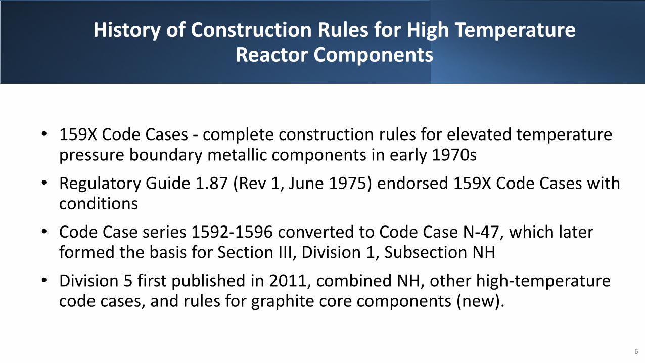
• 159X Code Cases - complete construction rules for elevated temperature pressure boundary metallic components in early 1970s
• Regulatory Guide 1.87 (Rev 1, June 1975) endorsed 159X Code Cases with conditions
• Code Case series 1592-1596 converted to Code Case N-47, which later formed the basis for Section III, Division 1, Subsection NH
• Division 5 first published in 2011, combined NH, other high-temperature code cases, and rules for graphite core components (new).
6
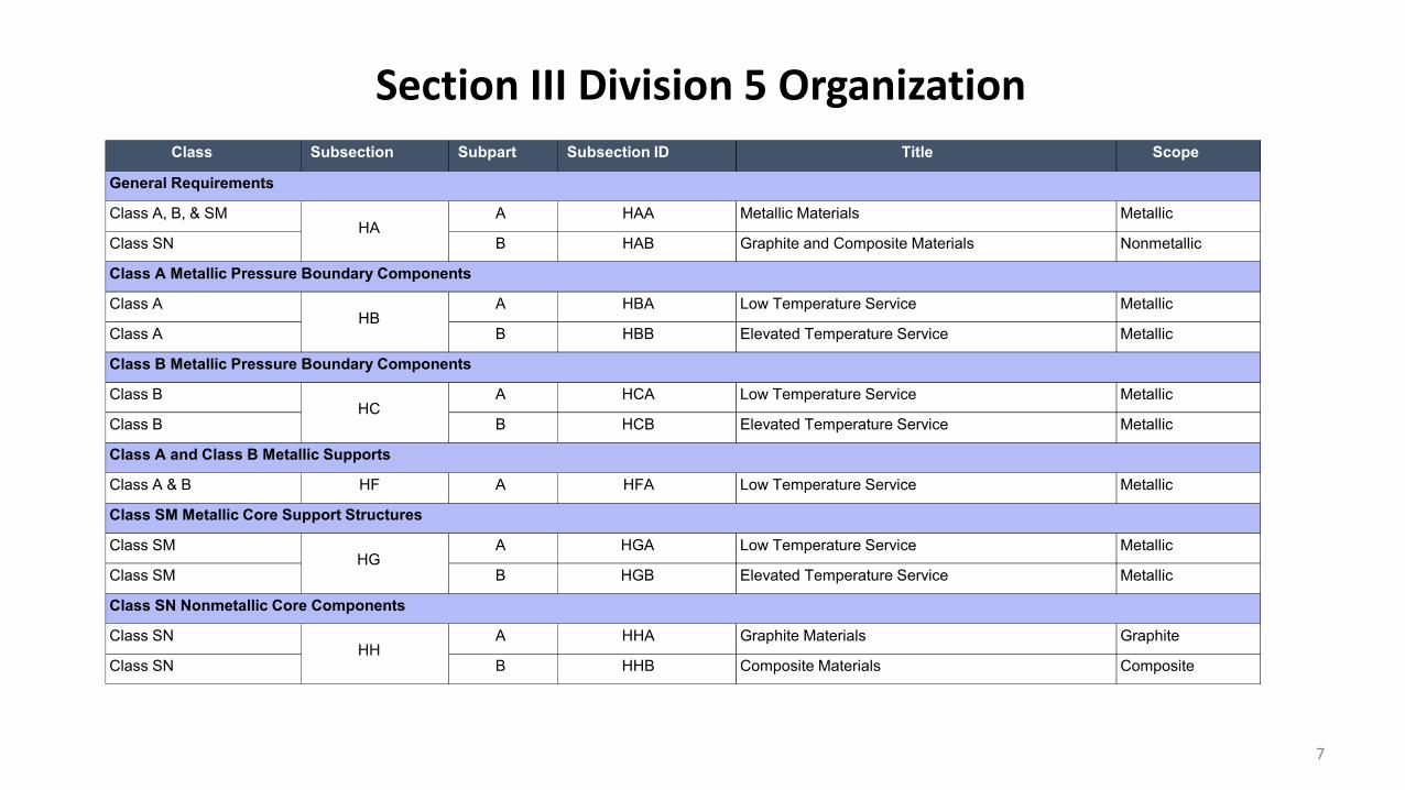
Class Subsection Subpart Subsection ID Title Scope
Class A, B, & SM A HAA Metallic Materials Metallic
Class SN B HAB Graphite and Composite Materials Nonmetallic
Class A A HBA Low Temperature Service Metallic
Class A B HBB Elevated Temperature Service Metallic
Class B A HCA Low Temperature Service Metallic
Class B B HCB Elevated Temperature Service Metallic
Class A & B HF A HFA Low Temperature Service Metallic
Class SM A HGA Low Temperature Service Metallic
Class SM B HGB Elevated Temperature Service Metallic
Class SN A HHA Graphite Materials Graphite
Class SN B HHB Composite Materials CompositeHH
Class B Metallic Pressure Boundary Components
General Requirements
Class A Metallic Pressure Boundary Components
Class A and Class B Metallic Supports
Class SN Nonmetallic Core Components
Class SM Metallic Core Support Structures
HA
HB
HC
HG
Section III Division 5 Organization
7
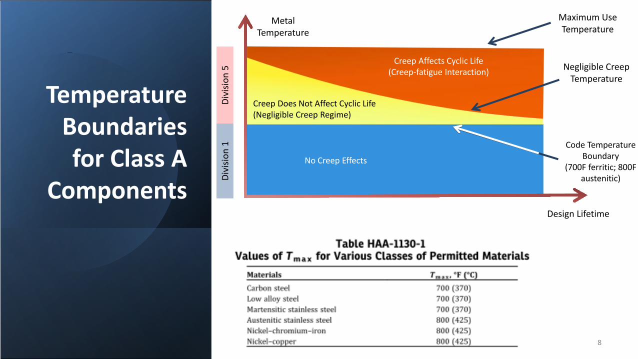
Temperature Boundaries for Class A
Components
Maximum UseTemperature
MetalTemperature
Design Lifetime
No Creep Effects
Creep Does Not Affect Cyclic Life(Negligible Creep Regime)
Creep Affects Cyclic Life(Creep-fatigue Interaction)
Divi
sion
5Di
visio
n 1
Negligible CreepTemperature
Code Temperature Boundary
(700F ferritic; 800F austenitic)
8

HBB Materials and Design Data
• Limited set of materials:– Type 304 Stainless Steel*– Type 316 Stainless Steel*– Alloy 800H– 2.25Cr-1Mo– 9Cr-1Mo-V (Grade 91)– Alloy 617 (Code Cases N-872 and N-898)
• Design parameters are mostly self contained in Division 5, except the following contained in Section II:– Elastic constants– Thermal properties– Part of yield strength (𝑆𝑆𝑦𝑦) table– Part of ultimate tensile strength (𝑆𝑆𝑢𝑢) table
Minimum carbon content of 0.04 weight % required for better high temperature properties – “Type 304H” and “Type 316H” – this designation is not used in Section III-5.
9

Failure Modes Addressed by Section III-5
Failure Mode Type Prevented By Location Analysis Method(s)
Plastic collapse Load controlled Primary load design HBB-3000 Elastic
Creep-rupture Load controlled Primary load design HBB-3000 Elastic
Creep-fatigue Deformation controlled Creep-fatigue rules HBB-T Elastic, Inelastic, EPP
Gross distortion due to incremental collapse and ratcheting
Deformation controlled Strain limits HBB-T Elastic, Inelastic, EPP
Buckling due to short-term loadings
Load controlled or strain controlled, or both
Buckling limits (time-independent)
HBB-T Elastic, Inelastic
Creep buckling due to long term loadings
Load controlled or strain controlled, or both
Buckling limits (time-dependent)
HBB-T Elastic, Inelastic
10

HBB Primary Load Design
• Based on elastic analysis.• “Load-controlled” • Uses stress classification and
linearization.• Design and service level load
checks.• Accounts for thermal aging
effects with factors on yield and ultimate strength
• Welds: Strength reduction factor applied
Single temperature, pressure, and set of forcesTime-independentUses allowable stress 𝑆𝑆𝑜𝑜Very similar to Section I and VIII
Time-history of loadingTime-dependentUses the allowable stress 𝑆𝑆𝑚𝑚𝑚𝑚
Unique to Division 5
Desig
n Lo
ad
Service Load
11

HBB - Allowable Stresses
• Both time-dependent and time-independent allowable stresses included.• S0 – Allowable stress for design loadings• Service Level Loading Allowable stresses
– Sm - Time independent– St - Time dependent– Smt – Allowable limit for general primary membrane stress for Service
Level A and B– Sr – Expected minimum stress-to-rupture. Used for Level D limits and
in deformation-controlled analyses (HBB-T)12

HBB - Basis for Allowable Stresses
• S0 – Equal to the higher of S values from Section II-D, Subpart 1, Table 1A, or 300,000 hour Smt
• Sm - From Section II-D, Table 2A, Sm values at lower temperatures, extended to higher temperatures using same criteria
• Smt is the lower of Sm (time-independent) and St (time-dependent)
13

HBB - Basis for St (HBB-
3221)
• The lowest of:(a) 100% of the average stress required to obtain a total (elastic, plastic, primary, and secondary creep) strain of 1%;(b) 80% of the minimum stress to cause initiation of tertiary creep; and(c) 67% of the minimum stress to cause rupture (Sr).
• Determination of St is inherently conservative because of the 80% and 67% factors applied to tertiary creep initiation and stress-to-rupture.
14

Other Stresses/Material
Properties
• Sy - yield stress as function of temperature
• Su - ultimate strength• R – Weld strength reduction factors• Tensile and yield strength reduction
factors for longtime services (Table HBB-3225-2)
• Isochronous stress-strain curves (ISSCs)
15
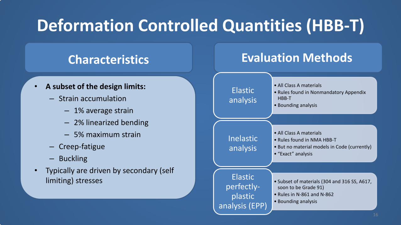
Deformation Controlled Quantities (HBB-T)
16
• All Class A materials• Rules found in Nonmandatory Appendix
HBB-T• Bounding analysis
Elastic analysis
• All Class A materials• Rules found in NMA HBB-T• But no material models in Code (currently)• “Exact” analysis
Inelastic analysis
• Subset of materials (304 and 316 SS, A617, soon to be Grade 91)
• Rules in N-861 and N-862• Bounding analysis
Elastic perfectly-
plastic analysis (EPP)
Characteristics
• A subset of the design limits:– Strain accumulation
– 1% average strain– 2% linearized bending– 5% maximum strain
– Creep-fatigue– Buckling
• Typically are driven by secondary (self limiting) stresses
Evaluation Methods

Creep-fatigue (HBB-T-1411)
• Basically:1. Compute creep damage
based on life fraction: 𝐷𝐷𝑐𝑐2. Compute fatigue damage
based on a cyclic life fraction: 𝐷𝐷𝑓𝑓
3. Consult interaction diagram for pass/fail
• Welds: same interaction diagram, factors on damage
17
Cree
p da
mag
e
Fatigue damage

Creep Damage (HBB-T-1433)• Construct a stress relaxation curve for each
hold in each cycle type• Determine creep damage with a time
fraction rule for each time interval ∑𝑖𝑖=1𝑛𝑛ℎ𝑜𝑜𝑜𝑜𝑜𝑜 ∆𝑚𝑚𝑖𝑖
𝑚𝑚𝑟𝑟 𝜎𝜎𝑖𝑖• Sum creep damage for all time intervals
needed to represent the specified elevated temperature service life 𝐷𝐷𝑐𝑐 = ∑𝑘𝑘=1
𝑞𝑞 ()
∆𝑡𝑡/𝑇𝑇𝑑𝑑 𝑘𝑘
• Database: creep rupture tests• Welds: use stress rupture factor to reduce
the creep rupture strength of the base metal
time
stress
Stress relaxation profile
Minimum stress-to-rupture for Alloy 617
18

Buckling and Instability (HBB-T-1500)• Limits for both time-independent
(creep not significant) and time-dependent (creep-significant) buckling are provided.
• Load factors for both load-controlled and strain-controlled bucking provided.
• Figures provide temperature/time combinations below which the time-independent buckling limits may be used.
• For conditions where stain-controlled and load-controlled buckling may interact, or significant elastic follow-up may occur, the load factors for load-controlled buckling are also to be used for strain-controlled bucking.
19
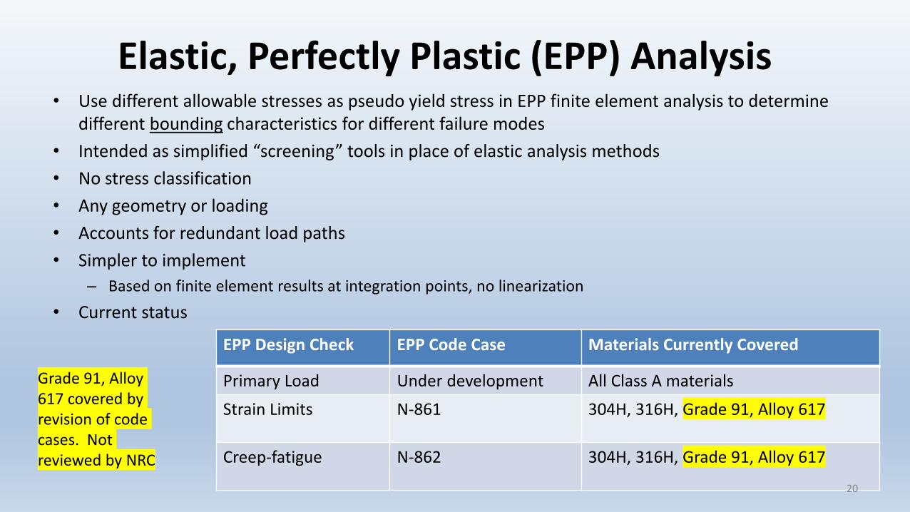
Elastic, Perfectly Plastic (EPP) Analysis• Use different allowable stresses as pseudo yield stress in EPP finite element analysis to determine
different bounding characteristics for different failure modes• Intended as simplified “screening” tools in place of elastic analysis methods• No stress classification• Any geometry or loading• Accounts for redundant load paths• Simpler to implement
– Based on finite element results at integration points, no linearization• Current status
EPP Design Check EPP Code Case Materials Currently Covered
Primary Load Under development All Class A materials
Strain Limits N-861 304H, 316H, Grade 91, Alloy 617
Creep-fatigue N-862 304H, 316H, Grade 91, Alloy 617
Grade 91, Alloy 617 covered by revision of code cases. Not reviewed by NRC
20
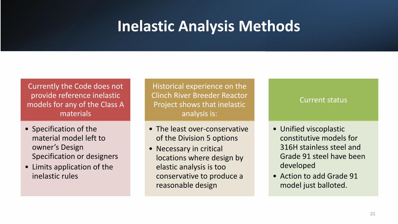
Inelastic Analysis Methods
Currently the Code does not provide reference inelastic
models for any of the Class A materials
• Specification of the material model left to owner’s Design Specification or designers
• Limits application of the inelastic rules
Historical experience on the Clinch River Breeder Reactor Project shows that inelastic
analysis is:
• The least over-conservative of the Division 5 options
• Necessary in critical locations where design by elastic analysis is too conservative to produce a reasonable design
Current status
• Unified viscoplastic constitutive models for 316H stainless steel and Grade 91 steel have been developed
• Action to add Grade 91 model just balloted.
21
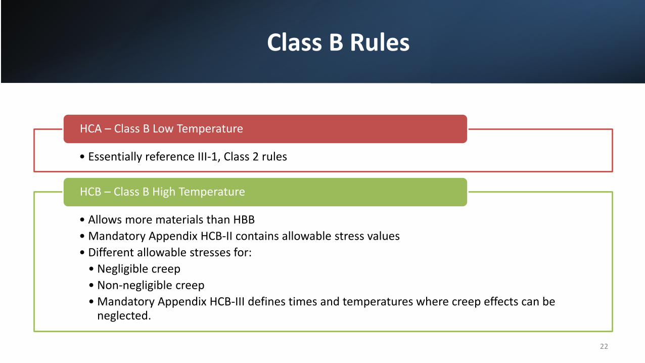
Class B Rules
• Essentially reference III-1, Class 2 rules
HCA – Class B Low Temperature
• Allows more materials than HBB• Mandatory Appendix HCB-II contains allowable stress values• Different allowable stresses for:
• Negligible creep• Non-negligible creep• Mandatory Appendix HCB-III defines times and temperatures where creep effects can be
neglected.
HCB – Class B High Temperature
22

Class B Rules
Extend rules of Division 1, Class 2 (Subsection NC) to elevated temperature service.
Based on a design-by-rule approach. “Design Lifetime” concept is not used.
Allowable stresses based on extrapolated 100,000 hour creep-rupture properties.
Fatigue damage from cyclic service is addressed only for piping with creep effects (HCB-3634).
23
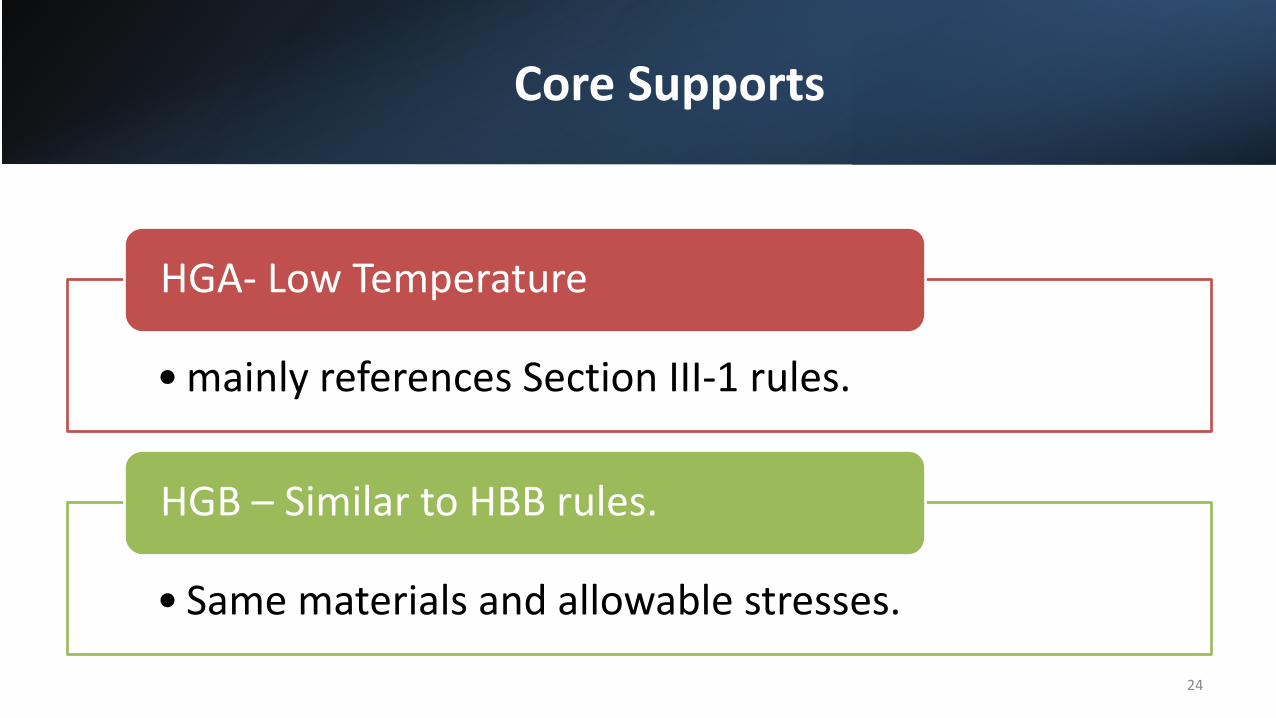
Core Supports
• mainly references Section III-1 rules.
HGA- Low Temperature
• Same materials and allowable stresses.
HGB – Similar to HBB rules.
24
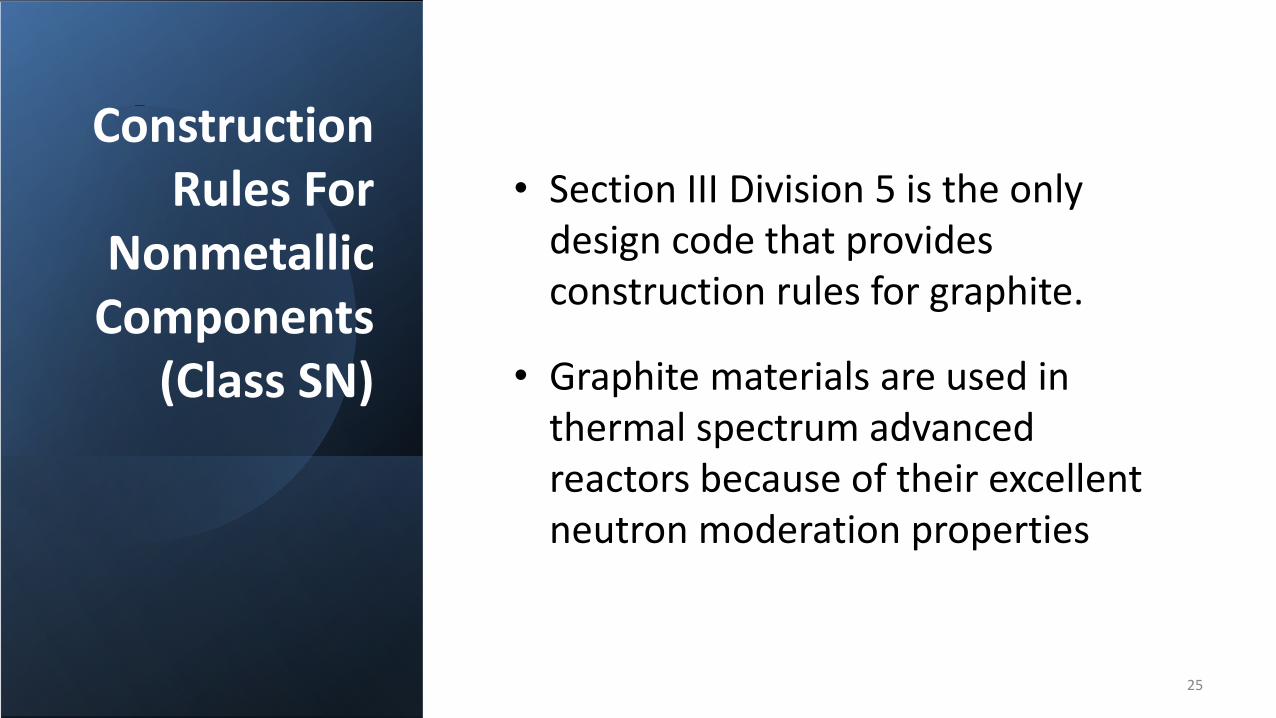
Construction Rules For
Nonmetallic Components
(Class SN)
• Section III Division 5 is the only design code that provides construction rules for graphite.
• Graphite materials are used in thermal spectrum advanced reactors because of their excellent neutron moderation properties
25

• There is no single “nuclear” grade of graphite –therefore, can’t design around a specific nuclear grade as metals can (i.e., 316H)
• Graphite is heterogeneous by nature, andcontains significant pores and cracks.
• Graphite is not ductile - Brittle or quasi-brittle fracture behavior
Graphite
Irradiation significantly alters the graphite behavior - Behavior is completely different before and after “turnaround” dose is achieved.
26
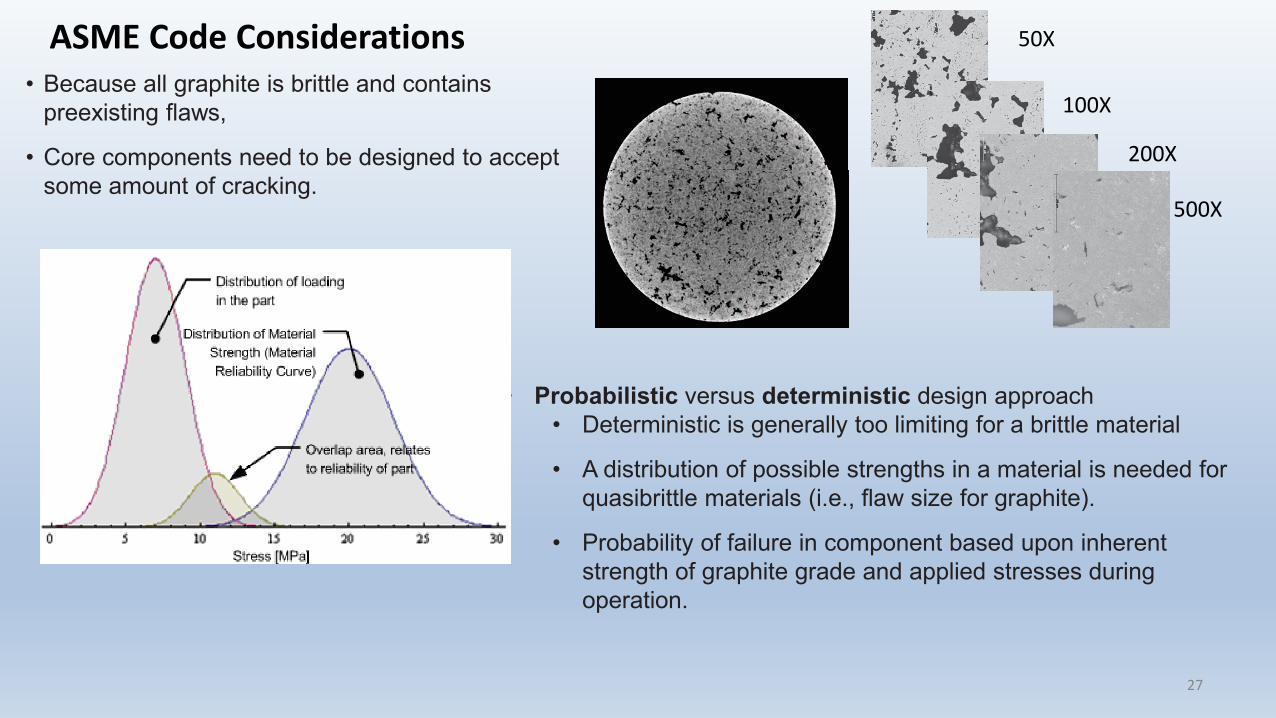
• Because all graphite is brittle and contains preexisting flaws,
• Core components need to be designed to accept some amount of cracking.
• Probabilistic versus deterministic design approach• Deterministic is generally too limiting for a brittle material
• A distribution of possible strengths in a material is needed for quasibrittle materials (i.e., flaw size for graphite).
• Probability of failure in component based upon inherent strength of graphite grade and applied stresses during operation.
50X
100X
200X
500X
ASME Code Considerations
27
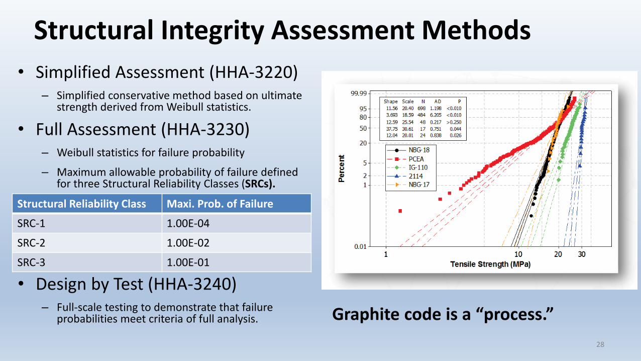
1. Simplified Analysis Method
• Simplified Assessment (HHA-3220)– Simplified conservative method based on ultimate
strength derived from Weibull statistics.
• Full Assessment (HHA-3230)– Weibull statistics for failure probability
– Maximum allowable probability of failure defined for three Structural Reliability Classes (SRCs).
• Design by Test (HHA-3240)– Full-scale testing to demonstrate that failure
probabilities meet criteria of full analysis.
Structural Integrity Assessment Methods
28
Structural Reliability Class Maxi. Prob. of Failure
SRC-1 1.00E-04
SRC-2 1.00E-02
SRC-3 1.00E-01
Graphite code is a “process.”
How to apply degradation to POF
From Dr. Mark Mitchell – PBMR Inc.
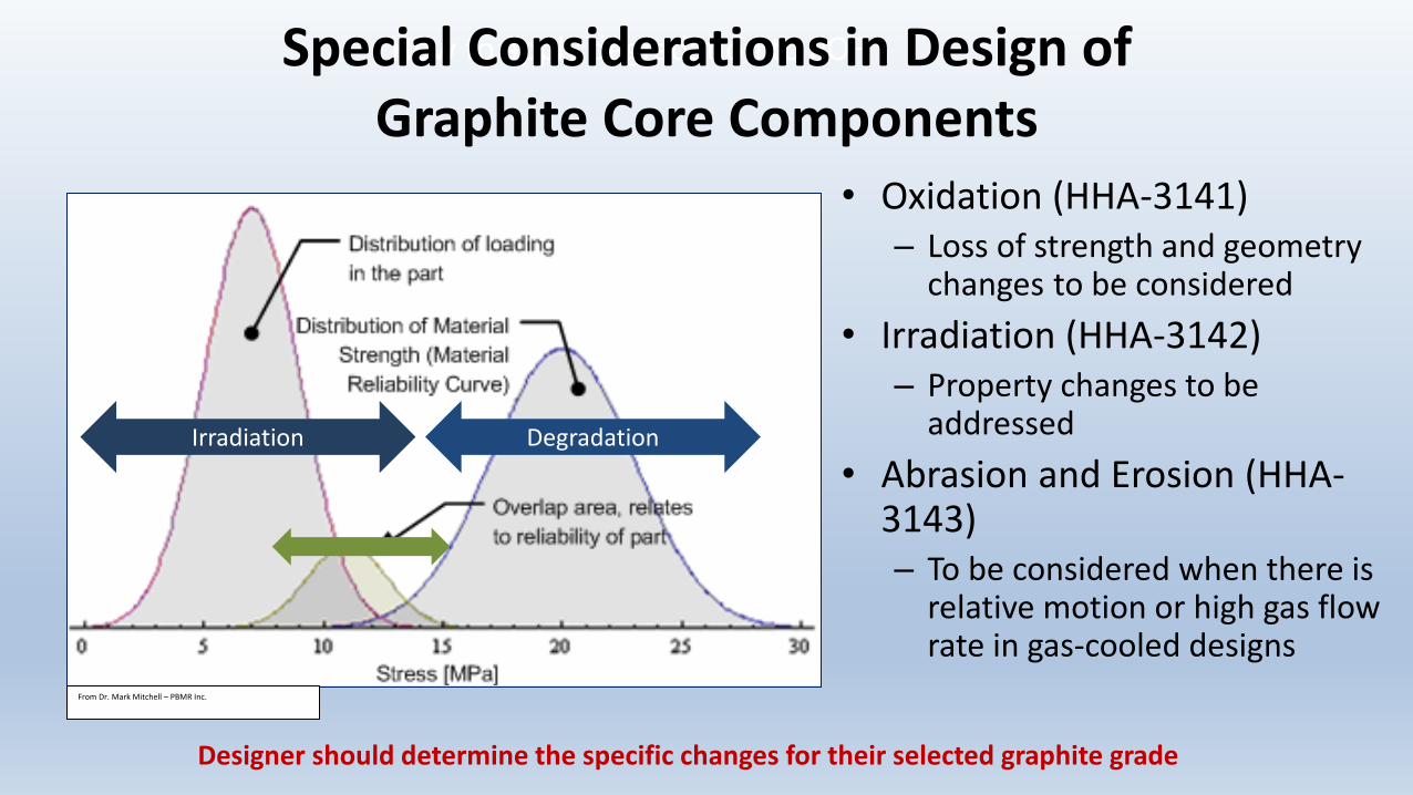
DegradationIrradiation
Designer should determine the specific changes for their selected graphite grade
• Oxidation (HHA-3141)– Loss of strength and geometry
changes to be considered• Irradiation (HHA-3142)
– Property changes to be addressed
• Abrasion and Erosion (HHA-3143)– To be considered when there is
relative motion or high gas flow rate in gas-cooled designs
Special Considerations in Design of Graphite Core Components
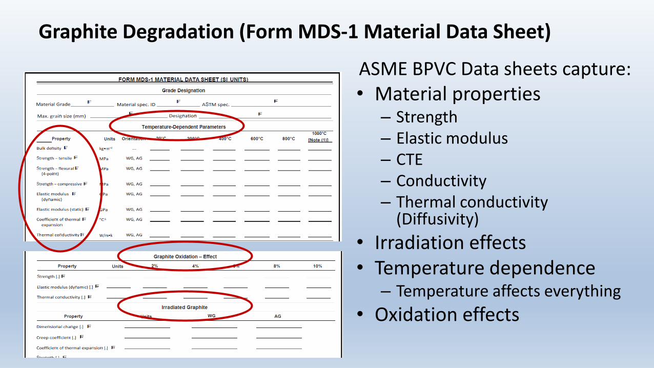
Graphite Degradation (Form MDS-1 Material Data Sheet)
ASME BPVC Data sheets capture:• Material properties
– Strength– Elastic modulus– CTE– Conductivity– Thermal conductivity
(Diffusivity)• Irradiation effects• Temperature dependence
– Temperature affects everything • Oxidation effects

Summary
31
Division 5 was issued as part of the 2011 Addenda to the 2010 Edition of the
BPV Code
Though the design rules development for metallic components traced all the
way to the 1960s
Division 5 covers the rules for the design, fabrication, inspection and testing of
components for high temperature nuclear
reactors
Construction rules for both metallic and nonmetallic
components are provided
The rules for nonmetallic components are unique among all design codes
world-wide
ASME Code committees are actively pursuing code rules
improvement and developing new
technologies to support “Advanced Nuclear”

NRC Review and Potential Endorsement of ASME BPVC, Section III, Division 5
Advisory Committee for Reactor SafeguardsJuly 20, 2021
Jeff Poehler, Sr. Materials EngineerReactor Engineering BranchOffice of Nuclear Regulatory Research
Jordan Hoellman, Project ManagerAdvanced Reactor Policy BranchOffice of Nuclear Reactor Regulation
Purpose
33
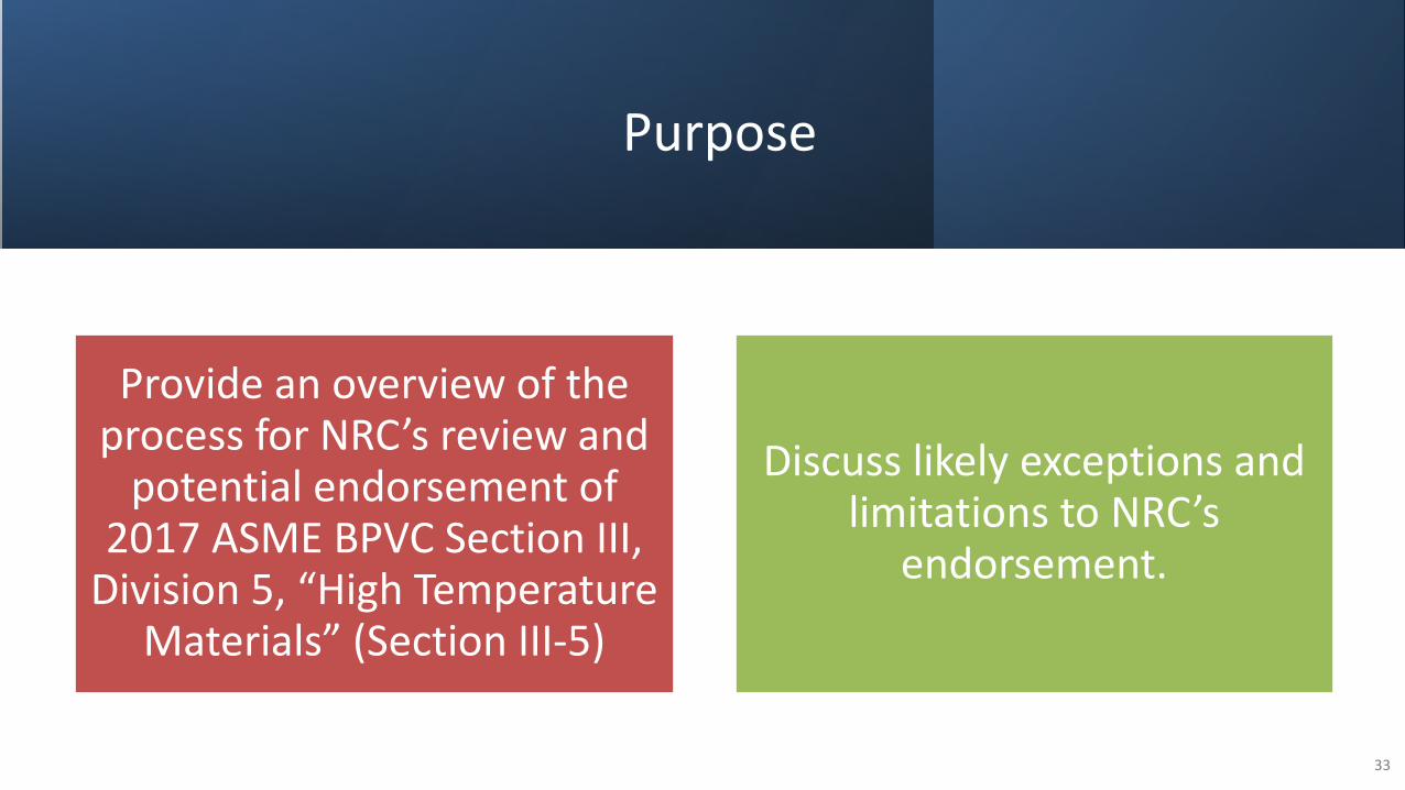
Provide an overview of the process for NRC’s review and
potential endorsement of 2017 ASME BPVC Section III,
Division 5, “High Temperature Materials” (Section III-5)
Discuss likely exceptions and limitations to NRC’s
endorsement.

NRC Guidance Documents for Section III-5 Endorsement
34
NUREG-2245 “Technical Review of the 2017 Edition of ASME Section III, Division 5, “High Temperature Reactors”
• Document the staff’s technical evaluation of the 2017 Edition of Section III, Division 5 and Code Cases N-861 and N-862 for acceptability and endorsement. Provide technical basis for DG-1380.
Regulatory Guide (RG) - Acceptability of ASME Section III, Division 5, “High Temperature Reactors”
(DG-1380)
• Describes an approach that is acceptable to the NRC staff to assure the mechanical/structural integrity of components for use in in elevated temperature environments, which are subject to time-dependent material properties and failure modes.
• Contains exceptions and limitations to the staff’s endorsement.
• The regulatory guide will update the guidance of RG 1.87.
• Appendix A of DG-1380 contains staff guidance on quality group classification for high-temperature reactors.

Scope of Staff Review
Section III-5, 2017 Edition• Did not review
Nonmandatory Appendix HBB-Y, so not endorsing.
1
Code Cases N-861 and N-862
2
Alloy 617 Code Cases• Separate technical basis
document being developed
• Will merge results into final DG-1380
3
35

Contractor Expert Recommendations
• To ensure an independent review of the technical adequacy of Section III, Division 5, NRC used contractors not directly involved with Division 5 code development
• NRC also used contractors more involved with code development on a limited basis to provide historical perspective on Division 5.
36

Review Process -General
37
Relied on previous reviews when possible.- Code Cases 1592-1596.- Section III, Division 1.
The NRC staff’s review was augmented by input from several national laboratories and commercial contractors.
See NRC’s Advanced Reactor Public Website: https://www.nrc.gov/reactors/new-reactors/advanced.html#endorev

38
Contractor Topics ML #PNNL Design, Fabrication, Examination, Testing (HBB/HCB/HGB-3000, 4000,
5000, 6000)Mechanical design appendixes for metallic core supports (HGB-I, HGB-II, HGB-III, HGB-IV)
ML20269A145
ORNL Materials (HBB/HCB/HGB-2000)Tables and Figures (Mandatory Appendix HBB-I-14)Guidelines for Restricted Material Specifications (Non-Mandatory Appendix HBB-U)
ML20269A125
NUMARK/EMC2
Mechanical Design Appendixes for Class A and Class B components (HBB-II, HBB-T, HCB-I, HCB-II, HCB-III)
ML20349A003
Technical Requirements – Graphite Materials and Design ML20358A145
Code Cases N-861 and N-862 (all aspects) ML20349A002
ANL Historical Context and Perspective on Materials Properties ML21090A033
Contractor Reports

Review Process – General Requirements
Staff compared the 2017 Edition of ASME Code III-5-HAA and -HAB to the 2017 Edition of ASME Code III-NCA to ensure consistency with what the NRC has endorsed in 10 CFR 50.55a.
Exceptions or limitations proposed where there are differences.
39
Similarly, the staff compared the 2017 Edition of ASME Code III-5-HAA and -HAB to the 2019 Edition of ASME Code III-5-HAA and -HAB to ensure consistency with those items that were corrected in the 2019 Edition.

General Requirements – Examples of
Exceptions/Limitations
Limitation: Staff does not endorse use of a Certifying Engineer who is not also a Registered Professional Engineer.
Basis: Consistency with a similar condition in 10 CFR 50.55a on 2017 Edition of Section III-NCA.
Limitation: When using HAB-3126(b), HAB-3127(b), and HAB-3855.3(c)(2) and (d)(2): The procurement documents should specify that the service will be provided in accordance with the accredited ISO/IEC 17025 program and scope of accreditation.
Basis: This is one of several limitations included for consistency with the updated ILAC accreditation process that is called out in NCA-3126 and also in the 2019 edition of Section III-5.
40
Mechanical Design – Exceptions and Limitations
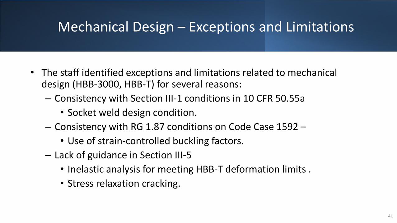
• The staff identified exceptions and limitations related to mechanical design (HBB-3000, HBB-T) for several reasons:– Consistency with Section III-1 conditions in 10 CFR 50.55a
• Socket weld design condition.– Consistency with RG 1.87 conditions on Code Case 1592 –
• Use of strain-controlled buckling factors.– Lack of guidance in Section III-5
• Inelastic analysis for meeting HBB-T deformation limits .• Stress relaxation cracking.
41

Mechanical Design –
Exceptions and Limitations –
Stress Relaxation Cracking
Limitation: When using HBB-T-1710 applicants and licensees should develop their own plans to address the potential for stress-relaxation cracking in their designs.
Basis: Stress relaxation cracking is a mechanism causing enhanced creep crack growth in certain materials caused by relaxation of weld residual stresses in components in high-temperature service. Section III-5 does not contain any provisions addressing stress-relaxation cracking.
42

Review Process –Metallic and Graphitic Materials
• Did not primarily rely on previous reviews. • Independent analysis of materials properties
and allowable stresses by NRC contractor.• Additional input by subject matter experts
familiar with the development of Section III-5.
Class A Metallic materials (HBB-I-14)
• Did not rely on previous reviews.• Graphite provisions were not in 159X Code
Cases – New to Section III-5.• Technical review of Section III-5 by subject
matter experts.
Graphite (HHA)
43
44
Metallic Materials
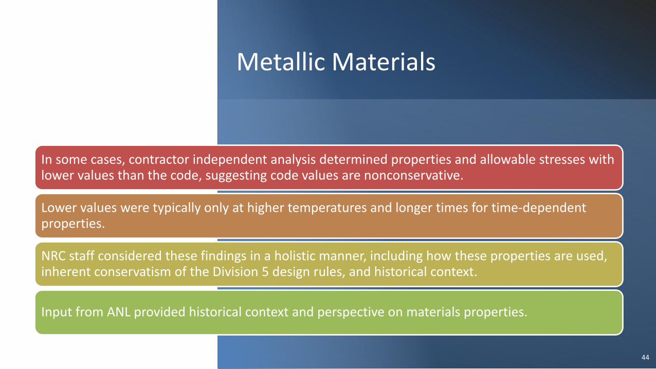
In some cases, contractor independent analysis determined properties and allowable stresses with lower values than the code, suggesting code values are nonconservative.
Lower values were typically only at higher temperatures and longer times for time-dependent properties.
NRC staff considered these findings in a holistic manner, including how these properties are used, inherent conservatism of the Division 5 design rules, and historical context.
Input from ANL provided historical context and perspective on materials properties.
Metallic Materials – Exceptions and Limitations
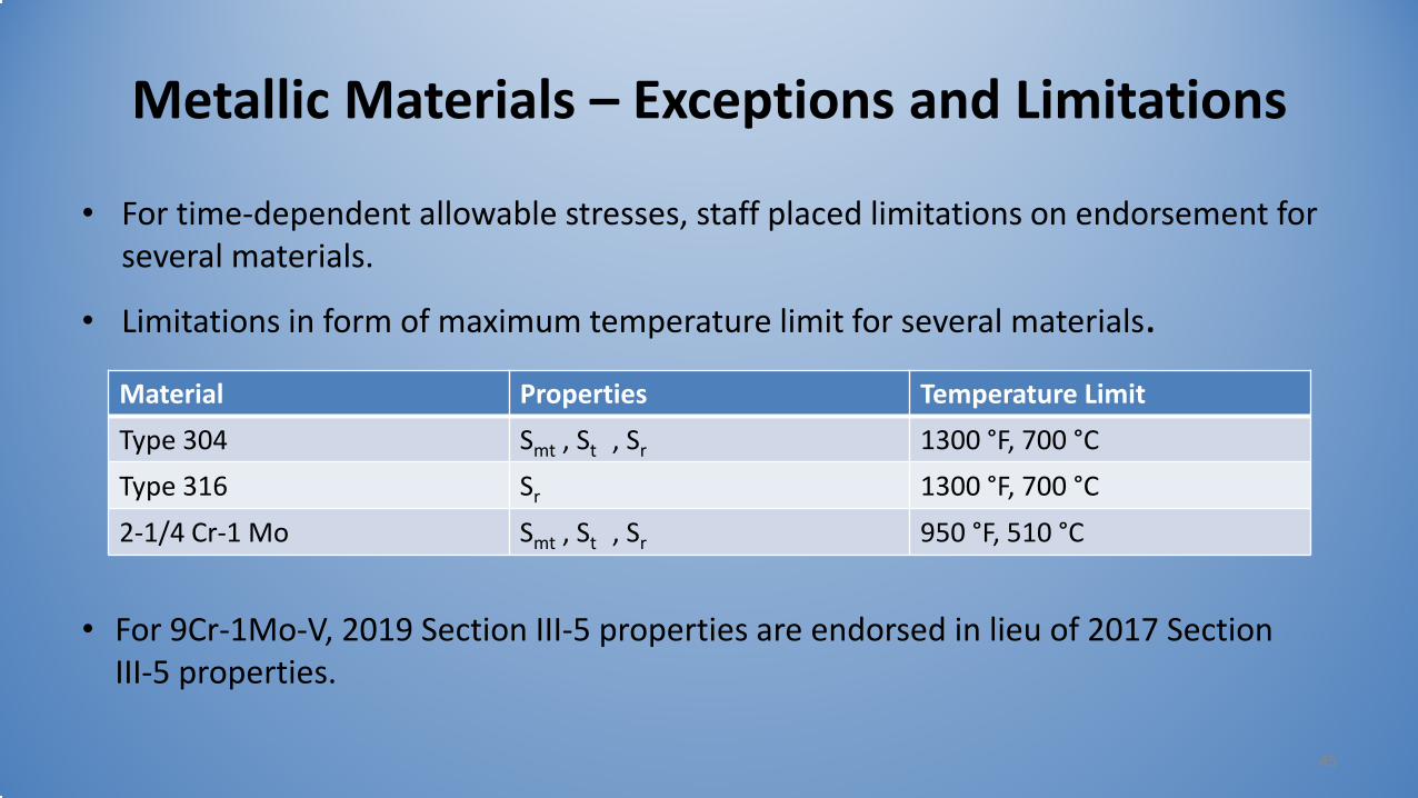
• For time-dependent allowable stresses, staff placed limitations on endorsement for several materials.
• Limitations in form of maximum temperature limit for several materials.
45
Material Properties Temperature LimitType 304 Smt , St , Sr 1300 °F, 700 °CType 316 Sr 1300 °F, 700 °C2-1/4 Cr-1 Mo Smt , St , Sr 950 °F, 510 °C
• For 9Cr-1Mo-V, 2019 Section III-5 properties are endorsed in lieu of 2017 Section III-5 properties.
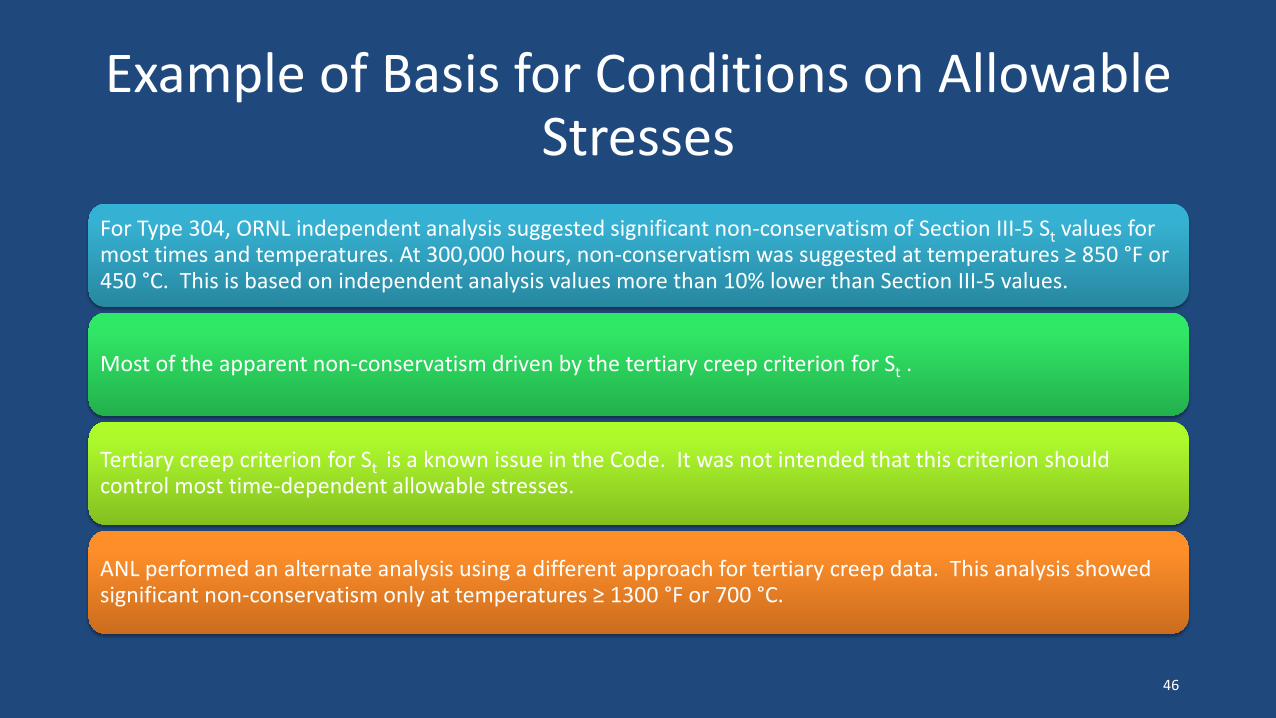
Example of Basis for Conditions on Allowable Stresses
For Type 304, ORNL independent analysis suggested significant non-conservatism of Section III-5 St values for most times and temperatures. At 300,000 hours, non-conservatism was suggested at temperatures ≥ 850 °F or 450 °C. This is based on independent analysis values more than 10% lower than Section III-5 values.
Most of the apparent non-conservatism driven by the tertiary creep criterion for St .
Tertiary creep criterion for St is a known issue in the Code. It was not intended that this criterion should control most time-dependent allowable stresses.
ANL performed an alternate analysis using a different approach for tertiary creep data. This analysis showed significant non-conservatism only at temperatures ≥ 1300 °F or 700 °C.
46

Graphite Materials and
Design
• Numark Associates Inc. provided a technical assessment of Subsection HH, “Class A Nonmetallic Core Support Structures,” Subpart A, “Graphite Materials.”
• Staff has completed the review of the above report and all applicable sections of ASME Section III, Division 5 and obtained clarifications and feedback from NRC contractors (NUMARK and INL) in order to come up with the conclusions identified in the NUREG.
• The staff's independent review of the code requirements considered the holistic design of graphite core support structures.
47
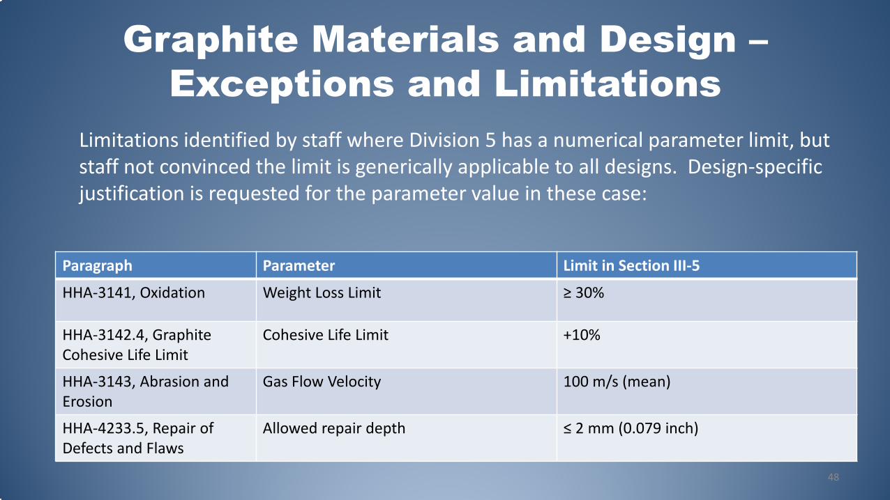
Graphite Materials and Design –Exceptions and Limitations
Paragraph Parameter Limit in Section III-5
HHA-3141, Oxidation Weight Loss Limit ≥ 30%
HHA-3142.4, Graphite Cohesive Life Limit
Cohesive Life Limit +10%
HHA-3143, Abrasion and Erosion
Gas Flow Velocity 100 m/s (mean)
HHA-4233.5, Repair of Defects and Flaws
Allowed repair depth ≤ 2 mm (0.079 inch)
48
Limitations identified by staff where Division 5 has a numerical parameter limit, but staff not convinced the limit is generically applicable to all designs. Design-specific justification is requested for the parameter value in these case:
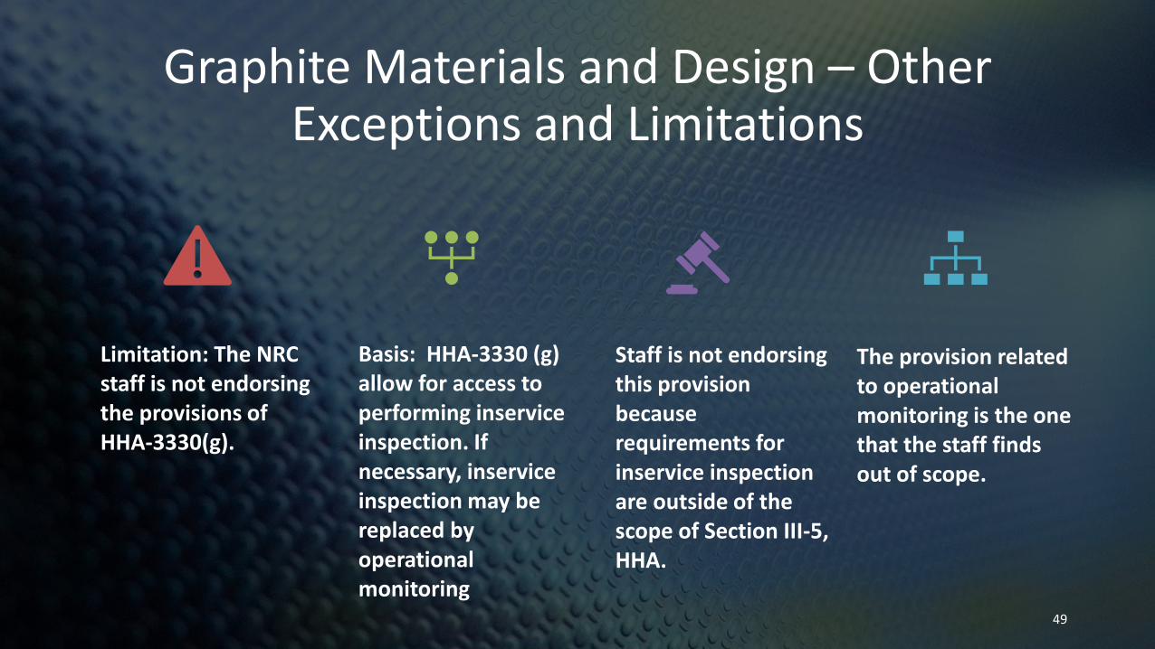
Graphite Materials and Design – Other Exceptions and Limitations
Limitation: The NRC staff is not endorsing the provisions of HHA-3330(g).
Basis: HHA-3330 (g) allow for access to performing inserviceinspection. If necessary, inserviceinspection may be replaced by operational monitoring
Staff is not endorsing this provision because requirements for inservice inspection are outside of the scope of Section III-5, HHA.
The provision related to operational monitoring is the one that the staff finds out of scope.
49

Four Quality Groups and associated standards (from DG-1380, Appendix A)
Quality Group A
• Safety-related SSCs• Use ASME
Section III, Division 5 Class A for safety related SSCs that have safety significance
Quality Group B
• Safety-related SSCs• Use ASME
Section III, Division 5 Class B for safety related SSCs with low safety significance
Quality Group C
• Non-safety-related SSCs with safety significance• Use ASME
Section VIII, Division 1 or 2
Quality Group D
• Non-safety-related SSCs with no special treatment• Owner to
establish standards for use
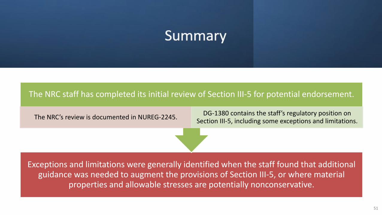
Summary
Exceptions and limitations were generally identified when the staff found that additional guidance was needed to augment the provisions of Section III-5, or where material
properties and allowable stresses are potentially nonconservative.
The NRC staff has completed its initial review of Section III-5 for potential endorsement.
The NRC’s review is documented in NUREG-2245. DG-1380 contains the staff’s regulatory position on Section III-5, including some exceptions and limitations.
51

Next Steps
The NUREG and DG will be issued for public comment.
Alloy 617 Code Cases technical review (in progress).
Make changes as necessary to NUREG and DG to address public comments.
Reissue DG for a second public comment period incorporating Alloy 617 results and resolution of public comments.
Issue draft Alloy 617 technical basis document concurrently with DG.
52