overview of extraction line designs and issues y. nosochkov (slac) on behalf of the 14 mrad, 2 mrad...
TRANSCRIPT

Overview of Extraction Line Designs and Issues
Y. Nosochkov (SLAC)On behalf of the 14 mrad, 2 mrad and head-on teams
ILC Interaction Region Engineering Design WorkshopSLAC, 17 – 21 September, 2007

IRENG07 2
• Goal: To review the main features and issues of the three extraction options designed for: 14 mrad crossing angle (baseline), 2 mrad, and head-on collision.• Largely based on the status presented at LCWS’07. Also, see a separate report by R. Appleby for details and updates in the 2 mrad design.• Work of many people.

IRENG07 3
Extraction designs for three crossing angle options:• 14 mrad (baseline), 2 mrad, and 0 mrad.Beam line:• 14 mrad: Independent straight line optics. One channel for e & .• 0 and 2 mrad: Initial magnets shared with incoming beam, separate e and channels.
IP
IP
14 mrad
2 mrad 0 mrad
DumpM. Woodley
e
e
e,

IRENG07 4
ILC ee collision creates disrupted beam:• Huge energy spread and large x,y divergence (emittance) in the outgoing electron beam.• High power divergent beamstrahlung photon beam going in the same direction with electrons.Issue:• Potential high beam loss in the extraction line due to overfocusing of low energy electrons and divergence of the photon beam.
Disrupted energy spread
beam size: in → out

IRENG07 5
Design considerations for the extraction line
• Beam channels: to safely transport the outgoing electron and photon beams from IP to main dump(s). • Large optical acceptance: to minimize beam loss from strong overfocusing and dispersion of low energy electrons. Requires careful optimization of energy dependent focusing and sufficient aperture.• Large geometric acceptance: to minimize beam loss from the divergent beamstrahlung photons. Requires large aperture increasing with distance.• Beam diagnostic system: to monitor luminosity, measure beam energy and polarization. Requires special downstream optics.• Collimation system: to protect magnets and post-IP diagnostic devices from unavoidable beam loss and undesirable background.• Main dump protection system: to avoid damage to dump window and prevent water boiling in the dump vessel from small undisrupted beam or under abnormal optical conditions (large errors, magnet failures). Requires enlargement of beam size at the dump window by optical means.
IRENG07 6
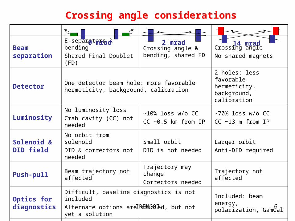
Beam separation
E-separators & bending
Shared Final Doublet (FD)Crossing angle & bending, shared FD
Crossing angle
No shared magnets
DetectorOne detector beam hole: more favorable hermeticity, background, calibration
2 holes: less favorable hermeticity, background, calibration
LuminosityNo luminosity loss
Crab cavity (CC) not needed
~10% loss w/o CC
CC ~0.5 km from IP
~70% loss w/o CC
CC ~13 m from IP
Solenoid & DID field
No orbit from solenoid
DID & correctors not needed
Small orbit
DID is not needed
Larger orbit
Anti-DID required
Push-pull Beam trajectory not affectedTrajectory may change
Correctors neededTrajectory not affected
Optics for diagnostics
Difficult, baseline diagnostics is not included
Alternate options are studied, but not yet a solutionIncluded: beam energy, polarization, GamCal
Transport (e,) Separate e, channels Separate e, channels Shared e, channel
Dumps (e,)Intermediate and main dumps with holes
One shared or two sepa-rate dumps with a hole
One shared dump without holes
Crossing angle considerations
14 mrad2 mrad0 mrad

IRENG07 7
Push-pull options
14 mrad: Push-pull optics for L*= 3.51, 4.0, 4.5 m is designed. SC magnets QD0/SD0/QDEX1 exchange with the detector. Long warm drift is reserved for break-in point. SC QF1/SF1/QFEX2A in a separate cryostat and other magnets outside of detector do not change, except fine strength tuning.
14 mrad
0 mrad
2 mrad
0 mrad: Optics studied for L*=4-6 m. Push-pull possible, does not change trajectories.
2 mrad: Push-pull not yet studied (but see R. Appleby’s update). It may affect extraction trajectory. Correctors needed.

IRENG07 8
Extraction beam optics
14 mrad:• No shared FD: easier optics. • Quadrupoles: to focus at Com-pton IP, optimized for minimal loss.• Dipole chicanes: for diagnostics - beam energy, polarization and GamCal.• Fast sweeping kickers: for dump protection.• Collimators: for magnet and diagnostic protection.0 and 2 mrad:• Shared FD & bending: optics is more difficult.• Minimal optics, few magnets, collimators: for bare beam transport to dump, optimized for minimal loss.• No diagnostic optics.• Sweeping kickers need to be included for dump protection.
14 mrad
2 mradIP

IRENG07 9
Extraction diagnostics: 14 mrad
Gamma Calorimeter
• Energy measurement using synchrotron radiation created in 8-bend vertical chicane with horizontal bump magnets.• Polarization measurement using laser to produce Compton-scattered electrons at extraction focal point in the 4-bend chicane.• Luminosity diagnostic using GamCal between 2 vertical bends.0 and 2 mrad: Baseline diagnostics not included.
IRENG07 10
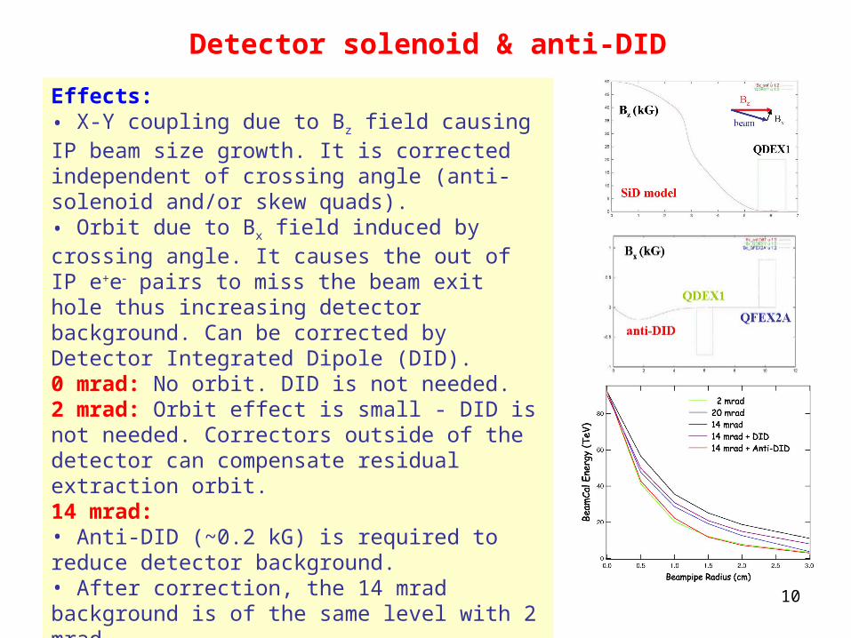
Detector solenoid & anti-DID
Effects:• X-Y coupling due to Bz field causing IP beam size growth. It is corrected independent of crossing angle (anti-solenoid and/or skew quads).• Orbit due to Bx field induced by crossing angle. It causes the out of IP e+e pairs to miss the beam exit hole thus increasing detector background. Can be corrected by Detector Integrated Dipole (DID).0 mrad: No orbit. DID is not needed.2 mrad: Orbit effect is small - DID is not needed. Correctors outside of the detector can compensate residual extraction orbit.14 mrad: • Anti-DID (~0.2 kG) is required to reduce detector background.• After correction, the 14 mrad background is of the same level with 2 mrad.• Corrector coils built on QDEX1, QFEX2A quads compensate the residual extraction orbit.

IRENG07 11
Fast sweeping system
14 mrad: System of fast (1 kHz) X-Y kickers is included to sweep bunches of each train in one turn on 3 cm circle at the dump window. It enlarges the beam area to protect from window damage and water boiling caused by very small beam size in cases of undisrupted beam or under certain abnormal optics conditions (large errors, magnet failures).0 and 2 mrad: Not in the current design, but can be included.
14 mrad

IRENG07 12
Superconducting magnets: 14 mrad
• Magnet design is well developed (BNL).• Based on compact SC technology.• Field shielding and correcting coils are built in.• 38 cm QD0 prototype was tested in solenoid field and showed excellent field and quench performance.• SC extraction quad parameters at 500 GeV CM:- QDEX1: L=1.06-1.19 m, G=86-98 T/m, R=15-18 mm,- QFEX2: L=1.1 m, G=31-36 T/m, R=30 mm.• SC magnets require upgrade for 1 TeV CM.

IRENG07 13
Superconducting magnets: 0 mrad
• Based on engineered LHC SC quadrupoles and sextupoles with R = 28 mm bore radius.• Other option: FNAL design of SC quadrupole with 35 mm bore radius.• NbTi coils to achieve 250 T/m (7 T) at 500 GeV CM.• Nb3Sn coils to achieve 370 T/m (10.5 T) for 1 TeV CM upgrade - preliminary – R&D needed.
500 GeV
1 TeV
LHC
FNAL

IRENG07 14
Superconducting magnets: 2 mrad
• QD0 will be based on LHC SC quadrupoles with R = 28 mm bore radius.• SD0 requires large R = 60 mm bore radius – needs to be designed.• NbTi coils to achieve 225 T/m (6.3 T at bore) at 500 GeV CM.• Nb3Sn coils for 350 T/m (8.8 T) for 1 TeV CM upgrade – preliminary – R&D needed.• QF1, SF1 are normal conducting warm magnets.

IRENG07 15
Other magnets: 14 mrad
• Magnets share e & beams.• Normal conducting bends and quadrupoles. Preliminary designs.• Field can be doubled for 1 TeV upgrade. Polarimeter and GamCal bends do not change field for 1 TeV.• Fast sweeping kickers assume TESLA design, but with larger aperture. Design feasible - to be done.
Kickers

IRENG07 16
Other magnets: 2 mrad
• Initial magnets share the outgoing diverging e & beams.• QF1, SF1: warm quadrupole and sextupole with 20 & 30 mm radius. Shared with incoming beam. Extracted beam goes off-axis through coil pockets → highly non-linear field. To be designed. • Panofsky type QEX1,2 quadrupoles with large aperture (100-115 mm) for e & beams. Must provide field free region for incoming beam (150 mm away). To be designed.• C-type warm BHEX1 bend for e & beams. Some residual field on incoming beam → requires correction. To be designed.• Sweeping kickers need to be included.
e

IRENG07 17
Other magnets: 0 mrad
• Extracted e & beams are transported through the incoming magnets which must have large aperture.• Initial 0.5 mrad deflection by 28 m E-separator overlapped with B-field.• C-type B1 & B2 bends with large aperture. To be designed.• Large aperture QD2A quad for 7 cm offset extracted e beam. To be designed.• QF3 septum quadrupole based on PEP2 IR magnet. To be designed.• Sweeping kickers need to be included.
IRENG07 18
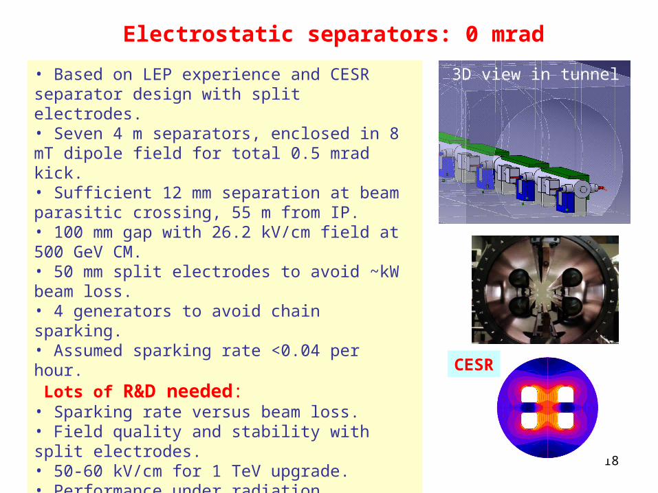
Electrostatic separators: 0 mrad
• Based on LEP experience and CESR separator design with split electrodes.• Seven 4 m separators, enclosed in 8 mT dipole field for total 0.5 mrad kick.• Sufficient 12 mm separation at beam parasitic crossing, 55 m from IP.• 100 mm gap with 26.2 kV/cm field at 500 GeV CM.• 50 mm split electrodes to avoid ~kW beam loss.• 4 generators to avoid chain sparking.• Assumed sparking rate <0.04 per hour. Lots of R&D needed: • Sparking rate versus beam loss.• Field quality and stability with split electrodes.• 50-60 kV/cm for 1 TeV upgrade.• Performance under radiation.• Insulator support design in harsh environment.• Optimal electrodes.• Sparking effects: field coupling through beam & , circuit effects, recovery.
3D view in tunnel
CESR

IRENG07 19
Beam power loss: 14 mradLow-P (c14) w/o solenoid
with solenoid
• No primary and photon loss on SC quads.• Large y-offset and y-angle at IP increase load on collimators. These non-ideal conditions need to be efficiently corrected.
• Quad focusing optimized for minimal beam loss.• 5 collimators to protect magnets, diagnos-tics and dump: COLE – for low energy collimation, COLCD – for Cherenkov detector protection, COLW1, COLW2, COLW3 – for fast kicker and dump protection.• Power loss is small at 500 GeV CM nominal parameters (c11), and acceptable at high disruption parameters (c14).

IRENG07 20
Beam power loss: 2 mrad
• FD is optimized for minimal loss.• Less than 1 W on SC QD0, SD0.• Acceptable loss on NC magnets.• Collimators to protect extraction magnets (load <5 kW).• Collimators to limit beam size at dump. May have high load (200 kW) in high luminosity option. Use rotating Al balls in flowing water.
High luminosity parameters
• Choice of separate or joint dumps for e & .• dump must have a hole for incoming beam.

IRENG07 21
Beam power loss: 0 mrad
• No loss on SC QD0, SD0. Up to 1 W loss on SC QF1, SF1 in low-P option.• 1-2 kW loss on separators w/o splitting, acceptable loss with split electrodes.• High power (650 kW) intermediate dump ~140 m from IP with two holes. Protects magnets from large angle photon and low energy electron loss. The dump model assumes Al & water 2.2 MW device at SLAC. Requires shielding protection. Backscattering to IP and E-separators needs to be checked. • Set of collimators to remove photon tails and limit incoming magnet aperture.• Main dump with a hole for incoming beam.

IRENG07 22
Summary of pros & cons(including input from Snowmass’05 BCD)
Advantages14 mrad: Independent flexible optics; larger magnet separation; downstream diagnostics; small to moderate beam loss; one beamline; one dump w/o holes; better compatible with and e-e- options.2 mrad: DID not needed; less dependent on crab-cavity; favorable detector hermeticity, background and calibration; small to moderate beam loss.0 mrad: Crab-cavity and DID not needed; favorable detector hermeticity, background and calibration.Disadvantages and R&D issues14 mrad: Crab-cavity, anti-DID & orbit correction required; less favorable detector background, hermeticity and calibration; SR in solenoid.2 mrad: No downstream diagnostics; shared FD; beam in non-linear field of QF1/SF1 coil pocket; large aperture SC sextupole; large aperture NC magnets close to incoming beam; SR in FD → photon backscattering; dump(s) with a hole; feedback BPM & kicker shared with disrupted beam.0 mrad: No downstream diagnostics; shared FD; least flexible optics; parasitic crossing; challenging E-separators; special large aperture incoming magnets; high power collimation ~140 m from IP → backscattering; intermediate and main dumps with holes; feedback BPM & kicker shared with disrupted beam.