overview of east diagnostics - fusion.gat.com
TRANSCRIPT

Overview of EAST diagnosticsOverview of EAST diagnostics
ASIPP ASIPP EAST Diagnostics research groupEAST Diagnostics research groupQing ZANGQing ZANG
July 10,2012July 10,2012
6TH US-PRC Magnetic Fusion Collaboration Workshop

OutlineOutline
Goals and topical issuesGoals and topical issues
Diagnostics in scheduleDiagnostics in schedule
Recently progress of some key diagnosticsRecently progress of some key diagnostics
Summary Summary

Goals and topical areaMain goals:
- long pulse discharge with high confinement and high performance
- help to resolve some ITER issues
Topical area:
- Transport an turbulence
- Plasma Control
- stability
- Heating and Current Drive
- Boundary and Divertor
- PSI

Physics issue Physical Quantity Possible Diagnostics
Transport and turbulence Te,n,
Ti, vΦ, vθ, nH,nD
High-k fluctuations
TS(core), HCN, ECE, reflectometryXCS,Neutron spectrometer,ERDCTS,ECEI
Plasma Control Ip,Vloop,Bp,Bt,B
Rogowki coils,externalloop,Internal loops,saddleloops,diamagnetic loops,pick-ipcoils
stabilityRadiated power,impurityCurrent Profile ,ELM instability
BolometrySXS,VS,VBGPI
Heating and Current Drive
Central current profileNeutrons
PolarimeterCountersHX
Boundary and DivertorTe, Ti ,n,<ñ˜f>, <ñ˜f˜T>, ˜
TS(edge) ,Probes (edge,divertor)Li beam
PWI erosion or deposition of plasma-facing materials LIBS
PhysicsPhysics issues with the measurementsissues with the measurements

Developing key diagnosticsDeveloping key diagnostics2006 2008 2010 2012 2014 2016 2018
First PlasmaCircular-OhmicElongated/Divertor-OhmicL-mode
4th EAST Campaign L- mode &H-mode
1MA,10keV,1000S
Core,5chs,10Hz,20mm-30mm 20(Core)+5(edge)chs,20Hz 30(Core)+10(edge)chs,50Hz
2004
r/a<0.5,30mm,100ms r/a<0.6,15mm,50ms
XUV:3*16channels 48 channels,40mm,5ms 48(H)+24(v)+16(D),30mm,2ms
16,98-126GHz,20mm, 10ms 32,104-168GHz+20,90-25GHz
V+W
250kHz,5x6channels
Second EAST campaign.
5th EAST Campaign 30s H-mode
TS
XCS
Bolometry
ECE
Reflectrometry
CXRS
BES
Neutrons counters
Neutrons spectrometer
Neutrons detector
GPI
Li beam
Ploarimeter
25channels,2-4cm,5-10ms;Ti:100-10000eV;Vi:2000m/s
2(3He)+1(235U) 4(3He)+4(235U)
1, BC501A,10%,5s 2,BC501A,8%,1s
6,20cm,50ms
2mm.2.5us,397100 f /sec
1ms
11 channels

Arrangement of EAST ports
ICRH3 (6) MW
ICRH3 (6) MW
LHCD4 MW
ICRF
NBI
Ha, CIII, OII, Li-I,Li-II, Mo-I,OMA, Reciprocating probe, ECE(16), HXS, Neutron(3He\BC-501),
RA,CO2
pellet
CIII,Da,vuv, Polarimetry,
DNBPXCS, TXCS, XEUV, SXR, AXUV, CXRS
ECRHCore TS Edge TS, Reflectometry,filterscope
HCN,IR camera
BES, VIS(visibleInspection system, GPI,
Divertor probe, Neutron(FC)
NBI
ECE(32), GPC, SXR,SX-PHA, Reciprocating probe, Bolometer,
Da, VB, AXUV LHCD
SXS
MBI
HX, Fast-Ha, ERD, HF-Glow
Diagnostics for temperature ,density and current
profiles measurement

Thomson scattering
L1L1
L2L2
P1P1
P2P2
LLMM
JJ
KK
properties:Core:
ne>0.5*1019m-3, Te>100eVSpatial res.:25+10 points,20mmTemporal res.:20Hz (50-100Hz),5kHz Points location:ρ=0-0.95aError estimate:absolute error,
Te<10%,ne<15%;statistic error<10%
Edge:ne>0.1*1019m-3, Te>10eVSpatial res.:10-15 points,5mmTemporal res.:>50HzPoints location:ρ=0.8-1.1aError estimate:absolute error
Te<10%,ne<15%; statistic error<10%
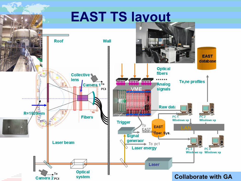
EAST TS layout
Collaborate with GA

0.5 0.6 0.7 0.8 0.9 10
500
1000
1500
Te
/eV
TeNe
0.5 0.6 0.7 0.8 0.9 10
2
4
6x 10¹⁹
Ne
/m-3
SHOT :40847at5s
0.5 0.6 0.7 0.8 0.9 10
500
1000
1500
Te
/eV
TeNe
0.5 0.6 0.7 0.8 0.9 10
2
4
6x 10¹⁹
Ne
/m-3
SHOT :40847at5.05s
ρ
One shot
ELM-free H-mode
ELM-ing H-mode

XCS setup on EAST
• Toroidal XCS– Similar structure with a slightly
toroidal view for rotation measurement
– Plasma coverage: ±45cm– Spectral resolution Δλ/λ~12,000 – Rotation normally determined
relative to a reference point • Polioidal XCS
– Plasma coverage: ±47cm– Spatial resolution ~3cm– Spectral resolution Δλ/λ~10,000 – Provide ion temperature profiles– Suffers from the low counting rate
of MWPC
2011‐10‐17
TXCS PXCS
PILATUS(~20ms)
Collaborate with PPPL& NFRI

LHCD plasma heating• With LHCD, Te increases substantially and Ti remain constant• Te profile peaks during LHCD phase with Ti profile unchanged
12
Results
LHCD plasma rotation measurement• Co-current rotation in L-mode plasma (counter-current on
Alcator C-Mod)• Broad rotation profile (core localized on Alcator C-Mod)

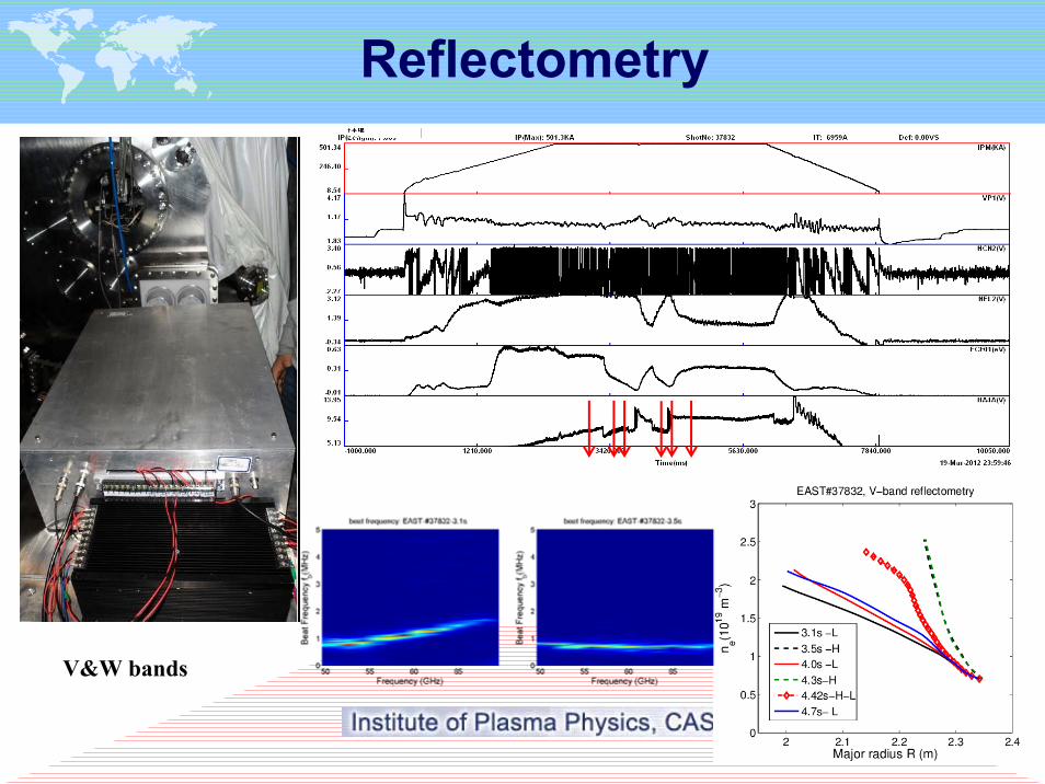
Reflectometry
EAS
plasm
Specification:
Frequency range: 50-75GHz(V band), 75-108GHz (W band) X-mode
positional uncertainty: ~ 5 mm (depending on the location of cutoff lawyer)
14
V&W bands
Reflectometry

1.35 1.4 1.45 1.5 1.55 1.6 1.65 1.7 1.75 1.80
200
400
600
800
1000
1200
1400
R (m)
T e (eV
)
Shot38402
ECE
BS1 BS2 BS3
104-168 GHz
104-
120
GH
z
120-
136
GH
z
136-
152
GH
z
51 GHz
To Band 1
59 GHz
To Band 2
67 GHz
To Band 3
75 GHz
152-168 GHz
To B
and
4
Calibration system
Collaborate with FRC
ECE signal for Island structure research
In collaboration with IFS, the University of Texas at Austin, a set of hot source calibration system for 16-channel radiometer has been planed on EAST.

Plan of 32-channel radiometer
Specification:Frequency range: 104-168GHz 2X-mode32 channels , 2GHz in-betweenTemporal resolution: ~1 us (depending on data acquisition)For plasma electron temperature profile measurementIn collaboration with UC Davis, a set of 32- channel radiometer
will be installed in EAST next campaign 1.35 1.4 1.45 1.5 1.55 1.6 1.65 1.7 1.75 1.80
200
400
600
800
1000
1200
1400
R (m)
T e (eV
)
Shot38402

Plan of 8-channel radiometer
An eight-channel heterodyne radiometer will be designed so as to directly measure the width of magnetic island.
8 channels, and 1GHz in-between channels
To measure the intensity of ECE in the vicinity of q=3/2 or q=2/1

Grating Polychromator
In collaboration with PPPL, a 20-channel Grating Polychromator has been tested on EAST to obtain electron temperature profile for discharges with large magnetic field in the future.

Other diagnostic systems
In collaboration with IFS, the University of Texas at Austin, a set of hot source calibration system for 16-channel radiometer has been planed on EAST.
19
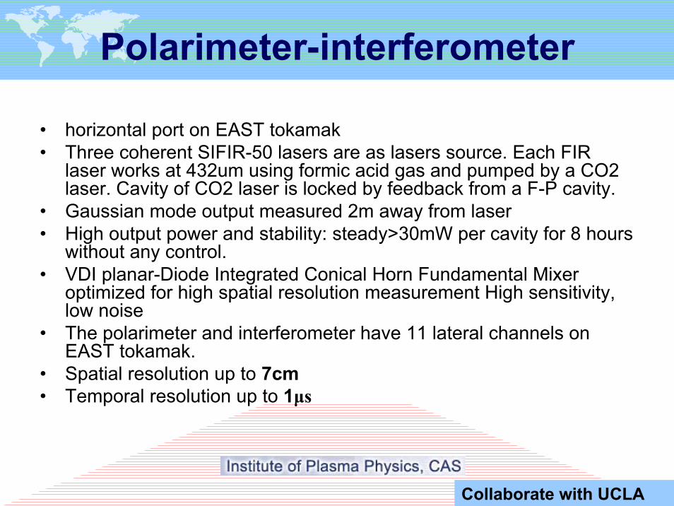
Polarimeter-interferometer
• horizontal port on EAST tokamak• Three coherent SIFIR-50 lasers are as lasers source. Each FIR
laser works at 432um using formic acid gas and pumped by a CO2 laser. Cavity of CO2 laser is locked by feedback from a F-P cavity.
• Gaussian mode output measured 2m away from laser• High output power and stability: steady>30mW per cavity for 8 hours
without any control. • VDI planar-Diode Integrated Conical Horn Fundamental Mixer
optimized for high spatial resolution measurement High sensitivity, low noise
• The polarimeter and interferometer have 11 lateral channels on EAST tokamak.
• Spatial resolution up to 7cm • Temporal resolution up to 1μs
Collaborate with UCLA

Diagnostics for Radiation
measurement

diagnostics Range lines Energy
Bolometer 7eV-6keV
Soft-X ray 1keV-13keV Fe Kα 6.4keV
PHA 2keV-30keV Cu Kα, Mo Kα 8.0keV, 17.4keV
EUV 100eV-400eV(30-110Å)
Radiation diagnostics

16channels*3 XUV array
48channels Metal resistor
XUV

24
PHA & Soft X-ray
4.3s Pre L-H4.5s ELMy-free4.8s @ H-L5.05s Pre L-H
3.3s Pre L-H3.4s ELMy-free3.9s Post H-L

EUV
During H-mode, confinement of impurity is increased, and both Continuous radiation and line radiation are enhanced at the same time

Filterscope
Collaborated with Oak Lab

272011‐10‐17 21st ITPA Topical Meeting on Diagnostics
Long-wavelength spectrometer
XEUV on EAST

• Measures the impurity spectra at the plasma edge– Passive measurement
• Suitable for all kinds of plasmas
– Wavelength range 450 – 600 nm (visible)
• C III & IV, He I & II, Li II, Ar II, Mo I & II
• CCD & optical fibers, spectrometer
– High transmission efficiency and quantum efficiency
• High resolution: <1 cm & 5 - 10 ms– Multiple sightlines– EMCCD
282011‐10‐17
ERD
Toroidal view
Poloidal view

CXRS,BES and FIDA
Three diagnostics are integrated together

CXRS & DC-BES• CXRS emission (active charge
exchange), for measurements of ni, Ti,Vi
• The light is collected by two optical periscopes: 25 channels poloidalperiscope and 25 channelstoroidal periscope and transmitted through two fiber bundles to holographic imaging spectrograph
• Spectrograph is set up to accept the light from all channels and spectrally disperse them onto the CCD detector, while keeping them spatially separated.
• A sequence of passive spectra in range of 300~800nm
• Chord separation for both systems is 2~4cm ,temporal is 5-10ms;
• Ti:100-10000eV;
• Vi:>2000/s
Collaborated with UT AUSTIN

Diagnostics for fluctuation
measurement
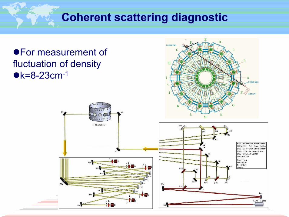
Coherent scattering diagnostic
For measurement of fluctuation of density
k=8-23cm-1
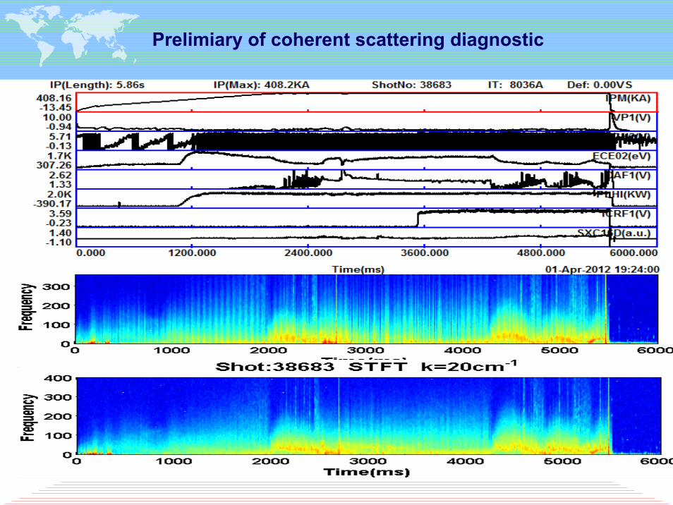
Prelimiary of coherent scattering diagnostic

AC-BES
• for measurement of fluctuation of density
• S/N>1;• f>250kHz;• Chord separation for
both poloidal and toroidaloptical views systems is 2~4cm
• Channels :32( 5 toroidal×6 poloidal);

Gas Puff imaging (GPI) System
Toroidal locations Poloidal locations
Puff manifoldOptical system
Two GPI systems in EAST tokamak, with about 67°angle in toroidal direction and up-down symmetry.
Rate: 397100 frames/sec, 64×64 pixels.
The objective plane of GPI is 130×130 mm, with 65 mm at the inner side of LCFS and 65mm at the outer side of LCFS.
The spatial resolution on objective plane is 2mm.
temporal resolution is 2.5μs
Collaborate with PPPL

Li-beam spectral diagnostic system
The aim of the diagnostic is two-dimensional edge plasma turbulence measurement with 1 microsecond time resolution, and edge electron density profile measurement with a few microsecond time resolution.
The schedule of this project:• Completion of detailed modeling: 30 August, 2012• Completion of the engineering design, review of plans: 30 September, 2012• Installation, testing and demonstration of vacuum system in Budapest: 15 January, 2013• Testing of observation system: 30 April, 2013• Final testing in Budapest: 15 May, 2013, The End-user shall participate the final testing
and confirm the testing result• Shipping all equipment to ASIPP before 15 June,2013• Installation on EAST: 15 July, 2013
Li atom beam Observation
Steering plates
Sodium cell
neutralizer
Li ion beam
AcceleratorIon source
K. McCormick et al. FED 34 125 (1997)
Collaborate with Wigner RCP

Diagnostics for Boundary and Divertor
measurement
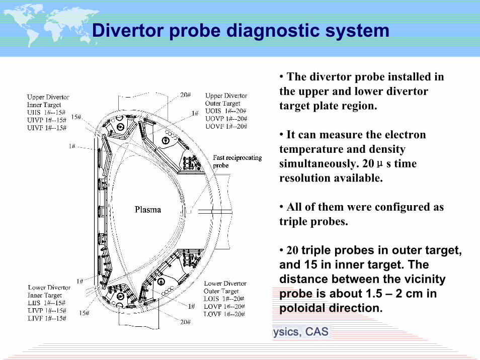
Divertor probe diagnostic system
• The divertor probe installed in the upper and lower divertortarget plate region.
• It can measure the electron temperature and density simultaneously. 20μs time resolution available.
• All of them were configured as triple probes.
• 20 triple probes in outer target, and 15 in inner target. The distance between the vicinity probe is about 1.5 – 2 cm in poloidal direction.

Divertor probe head assembly
Probe assembly
Divertor probes installed in the target plate

Fast reciprocating probe diagnostics system
Two FRPSs are installed in the horizontal ports A and E on EAST, separated 89° from each other in the toroidal direction. The poloidal cross‐section shows the probe on the out midplane of EAST.

Fast reciprocating probe in A portFast reciprocating probe in E port
Fast reciprocating probe diagnostics system

A stepping motor system drives the probe closed to plasma before plasma discharge .A servo motor system drives the probe at a high velocity (maximum 2m/s) during plasma discharge .A small chamber for
probe replace installed in front of the probe system.Up to 10 MHz sample rate.
Mechanical structure of the probe system

Diagnostics for PWI
research

Diagnostics for PWI
Laser Induced Breakdown Spectroscopy (LIBS)Laser shots on wall surface induces a tiny plasma plume, and spectra from the plume are recorded for analysis to the wall composition (H retention), both area and depth profiles Ok. In collaboration with Dalian University of Technology, a LIBS system is under development at laboratory, and will be connected to EAST horizontal port (H) next campaign.
1. LaserA Q-switched Nd:YAG laser 5 ns pulse width10 Hz repetition1064/532/355nm wavelength360/180/90 mJ (max)
2. Applied spectrometerLIBS2500+ (Ocean Optics Inc, USA) detection system with seven linear silicon CCD array detectors (200 to 980 nm with a single laser pulse).
Diagnostics for PWI
200 300 400 500 600 700 800 9000
1500
3000
0
1500
3000
Na Si
Si
SiSi
Si
Ca
Ar ArArAr
Ar
Ar
Ar
ArAr
Inte
nsity
(a.u
.)
original tile
Wavelength (nm)
Ar
TiH O C
Li
Li Li
Li
Inte
nsity
(a.u
.)
used tile
Li Na
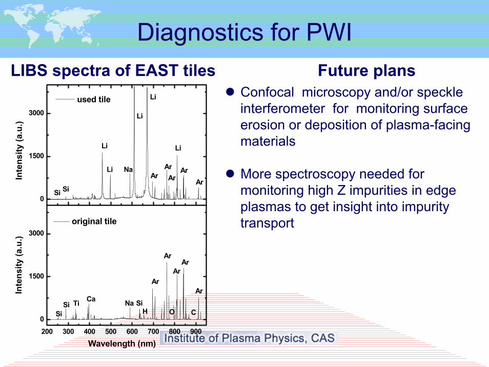
LIBS spectra of EAST tiles Future plansConfocal microscopy and/or speckle interferometer for monitoring surface erosion or deposition of plasma-facing materials
More spectroscopy needed for monitoring high Z impurities in edge plasmas to get insight into impurity transport

Summary
Much of diagnostic development and diagnostic implementation on EAST has been done in the past several years
Parts of them are based on the collaborations between ASIPP (proprietor of EAST) and US universities, national laboratories and industry.
These collaborations have been proved to be extremely successful and we hope we can extend relative collaborations in the area of diagnostics in the coming years.
