overview of doe/ornl heat pump design model and use of web version c. keith rice oak ridge national...
TRANSCRIPT

Overview of DOE/ORNL Heat Pump Design Modeland Use of Web Version
C. Keith Rice
Oak Ridge National Lab
January 2001

Outline - First Part
• HPDM History• General Capabilities• HX Assumptions• Solution Approach• Application Modeling
– Design Analysis
– Off-Design Simulation
• Flow Control Types

Outline - Second Part
• Web Version– Sample Run
– Input Screens
– Design Case
– Off-Design Setup
– Parametrics
– Plans
• Mark VI Version– Plans

History of DOE/ORNL Heat Pump Model
MIT Origin ORNL Version Mark I Mark III1976 1978 1982 1985
(3 Programs) (1 Program) (Industry Workshop)
(First PC Version)
Variable-SpeedWith
Charge Inventory
Mark IV(MODCON)
Mark VI(GLIDEZ)
1988 1991-93 1994-97 1998-01
(Cap. Mod. Workshop)
(ECM Variable -Speed, Design Parametrics)
(Pure, Near-Azeo HFCs, Propane)
(More HFC-Capable, More HX Configs.)
Mark V(PUREZ)
Web Interface

Applications of DOE/ORNL Heat Pump Model
MIT Origin ORNL Version Mark I Mark III1976 1978 1982 1985
Climate Master/GSHP Design ICP/HP Design, Ratings
Variable-SpeedWith
Charge Inventory
Mark IV(MODCON)
Mark VI(GLIDEZ)
1988 1991-93 1994-97 1998-01
Mark V(PUREZ)
ADL/CFC Mixtures,w-to-w HXs
Trane/Expert HX Design
LBL/RAC Standards
Battelle, Borg-Warner/Engine-Driven HPs
LBL/AC & HP Stds.
Allied/R-410A
Nordyne/ HP Design,Ratings
EPRI/vs RooftopEvaluation
Copeland(Windows Interface,Compressor Database)
Proctor - PG&E/Peak Cooling Designs

General Capabilities
• Air-to-Air Heat Pumps– Steady-State Cooling and Heating – Hardware-Based Representations
• Fin-and-Tube HXs
• Compressor Performance Maps
• Single- or Variable-Speed Compr/Fans
– Explicit or Implicit Flow Controls
Design/Simulation Capabilities
• Design or Off-Design Analysis– Charge Inventory Calculation or Balancing
• Sizing Options– For compressors and flow controls
• 1- or 2-Variable Parametrics

HX Assumptions
• Parallel Equivalent Circuits– Equal Flow Split– Single Circuit Analysis– Much Faster than Tube-by-Tube
• But More Idealized
• No Circuit Branching
– Assumes a Well-Balanced HX Design• With Two-Phase Regions Dominant

AirFlow
RefrigerantFlowSub-Circuit
Finned Tube Heat Exchanger With Parallel Circuits

HX Assumptions
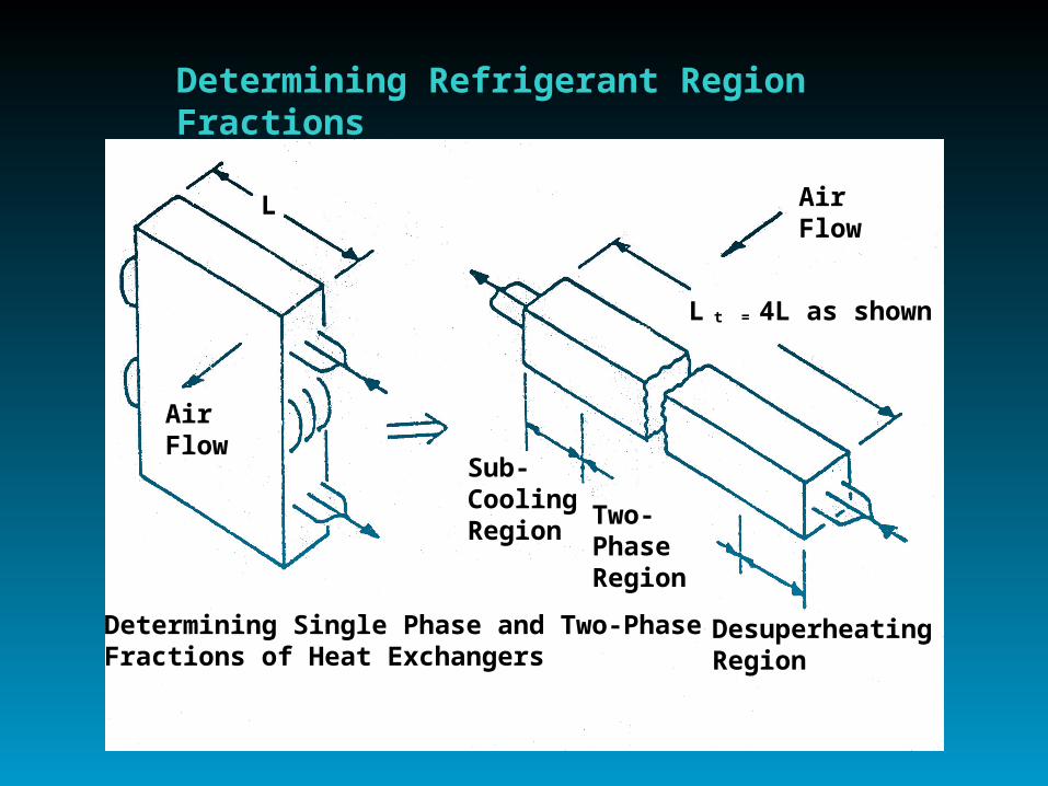
• Region-by-Region Refr.-Side Analysis– For Heat Transfer and Pressure Drop
• 3-Region Condenser, 2-Region Evap
– Crossflow Treatment of Airflow• Airflow Across Single-Phase Regions
Determined by Refr. Fraction
• Also Suitable When Single-Phase Regions Ahead of Two-Phase
AirFlow
Determining Single Phase and Two-PhaseFractions of Heat Exchangers
L
Sub-CoolingRegion
Two-PhaseRegion
AirFlow
DesuperheatingRegion
L t = 4L as shown
Determining Refrigerant Region Fractions

AirFlow
RefrigerantFlowSub-Circuit
Circuitry with Single-Phase Regions on Leading Edge

HX Assumptions
• Air-to Refrigerant H.T. Within Regions– Effectiveness/NTU Relations– Single-Phase Regions
• Many-Row Unmixed on Both Sides
– Two-Phase Regions• Use Two-Phase Temp. At Average Pressure
• Configuration Independent

Solution Approach• Successive Substitution (Sequential)
– Specify • Inlet Air Temps
• HX Exit Conditions/Control
• Or Design Charge in Place of One Condition
– Guess Saturation Temps
• Generally Fast, Stable Convergence– Always Solving a Real System– Easier to Trace Problems That May Occur
than with Simultaneous Solution Methods
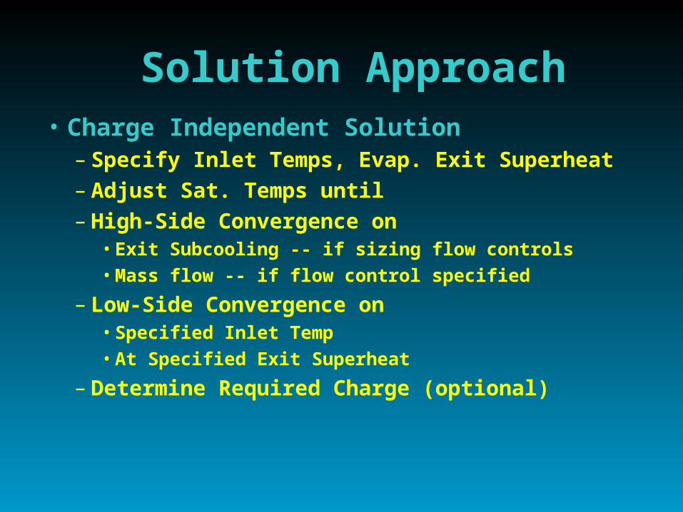
Solution Approach• Charge Independent Solution
– Specify Inlet Temps, Evap. Exit Superheat– Adjust Sat. Temps until – High-Side Convergence on
• Exit Subcooling -- if sizing flow controls• Mass flow -- if flow control specified
– Low-Side Convergence on• Specified Inlet Temp• At Specified Exit Superheat
– Determine Required Charge (optional)
Solution Approach
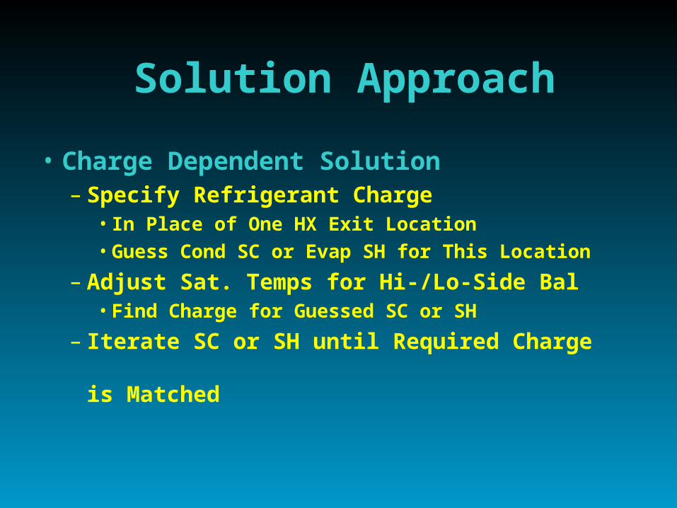
• Charge Dependent Solution– Specify Refrigerant Charge
• In Place of One HX Exit Location
• Guess Cond SC or Evap SH for This Location
– Adjust Sat. Temps for Hi-/Lo-Side Bal• Find Charge for Guessed SC or SH
– Iterate SC or SH until Required Charge is Matched

Application Modeling
• Design Analysis– Specify for Application
• Design Ambient Conditions
• Design Values of SC and SH
• And (optionally) Design Capacity
– Calculate • Required Charge and Flow Control Sizes
• And (optionally) Required Compressor Size
• Design Performance with Given HXs

Application Modeling
• Off-Design Simulation– Specify for Application
• Off-Design Ambient Conditions
• Design Charge and Flow Control Type/Size
• Compressor Size
– Calculate • Cond SC and Evap SH
• Off-Design Performance with Given Equipment

Cap Tube Flow Control -- Fixed Charge w Accum

Flow Control Types• Explicit
– Capillary Tube(s)• with fixed SH or charge
– Short-Tube Orifice(s)
• with fixed SH or charge
– Thermal Expansion Valve (TXV)• Fixed Opening
– if fixed SH
• Variable Opening
– if fixed charge
Flow Control Types• Implicit
– SH Control • fixed charge and SH
– SC Control• fixed charge and SC (SH may vary widely)
– SH/SC Control• fixed SC and SH• (simple way to approx. TXV, TEV)
– SH/SC Programmed Control • SC and/or SH controlled as F(ambient or speed)• Useful way to specify known SC/SH trends

Web Addresshttp://erendev.nrel.gov/buildings/tools_directory/
DOE Web Site for Software Tools

Web Version of HPDM
• Mark V • Single-Speed Only• 1-D Parametrics• Online X-Y Plots• Exportable Data
– Input & Output
Web Addresswww.ornl.gov/~wlj/hpdm/doehpdm.html

Demo of Web Version
• Model Walk Through (shown online)– Overview of Input Sheets
– Sample Design Run• View Cycle Output
– Setup Charge/Flow Control Values for Off-Design Run
– Run Off-Design Ambient Parametrics• View Output Options

Web Version of HPDM
• Mark V • Single-Speed Only• 1-D Parametrics• Online X-Y Plots• Exportable Data
– Input & Output
Web Addresswww.ornl.gov/~wlj/hpdm/doehpdm.html
Click Above To RunClick Above To Run

Web Release Plans
• Mark V– Updated Web Version, Spring 2001
• Improved Input Screens
• New Output Screen
• Setup Option for Off-Design Analysis
• Off-Design SH/SC Control vs Ambient
• 2-D Parametrics and Plotting
• Online Documentation and Related Papers

Example of Two-Variable Design ParametricsEER for a Range of Tube IDs and Circuits

Mark VI Version
• More HFC-Capable– New Props for HFC Mixtures
• Improved Near-Critical and Transport Props for Existing Fluids
– HFC-Suitable Two-Phase H.T. • U. of I. ACRC Correlations
– HFC-Suitable Flow Controls• Cap- and Short- Tube Correlations
• Refrigerant-Specific and -Generalized as Avail

Subcooled Enthalpy Corrections Are Needed For R-410A at Higher Condensing Temperatures

Cooling COP Comparisons for R-410A Over a Range of Condensing Temps
With Different Property Representations

Mark VI Version
• More HX Configurations– Circuit Branching
• Merging in Condenser Subcooled Region
– Circuit Arrangement• Initially 1- to N-Row CrossF
• Later Two-Phase with Glide Effect– Adding CrossCF, CrossPF
Mark VI Version
• More Air- and Refr-Side Surfaces– Air-Side
• All New Correlations for Range of Surfaces– Default Fin Patterns Built-In
• Extra Fin Area Calculated Explictly
– Refrigerant-Side• Based on Augmented-Area-Ratio Input
• Better Airflow and Fan Power Tracking– with ambient

Web Release Plans
• Mark VI– Initial Beta Release Web Version,
Summer 2001– Official Web Release, Fall 2001
• Link with Compressor Manuf Databases
– R-407C Capability To Follow Later