overview of dc technology - energy conversionicrepq.com/icrepq'13/396-onederra.pdf · bilbao...
TRANSCRIPT
International Conference on Renewable Energies and Power Quality (ICREPQ’13)
Bilbao (Spain), 20th to 22
th March, 2013
Renewable Energy and Power Quality Journal (RE&PQJ)
ISSN 2172-038 X, No.11, March 2013
Overview of DC technology - Energy conversion
O. Oñederra, H. Odriozola, E. Planas, I. López and V. López
Department of Electronics Technology
University of the Basque Country (UPV/EHU), Alameda de Urquijo s/n, E-48013 Bilbao,
e-mail: [email protected]
Abstract. DC transmission and distribution systems have
several advantages compared to classical AC system. This paper presents a review of DC technology, doing a special mention in HVDC. It addresses some issues like HVDC converter types, DC-
DC converter topologies, DC transmission and distribution topologies, transmission cables and DC circuit breakers with the main manufacturers and commercial devices.
Key words
HVDC, LVDC, DC microgrids, DC circuit breakers, DC power
converters.
1. Introduction
The electrical energy demand is increasing and a possible
alternative to meet these needs is the use of distributed
generation (DG) [1], allowing a better use of local energy
sources for local loads. The direct current (DC)
transmission and distribution (T&D) system is a way to
meet with the DG sources, such as photovoltaic, fuel cells
or wind generators [2].
The beginning of electrical energy transmission was using
DC transmission systems. It was generated by dynamos or
by Volta’s batteries to supply energy to arc-lighting and
motors. In 1882, Thomas Alva Edison installed his low
voltage DC (LVDC) system in the famous Pearl Street
Station, in New York, U.S.A., to supply energy to the
incandescent bulbs that he invented in 1879 [3]. In 1891, the
―war of currents‖, starring by T.A. Edison with John
Pierpont supporting DC and George Westinghouse with
Nikola Tesla supporting alternating current (AC) systems,
was finished concluding AC system as the winner due to less losses and less costs in transmission. This was due to an
easy way to step up voltage allowing less current
transmission and the use of less copper, making the system
cheaper (AC costs: $399,000 vs. DC costs: $554,000) [3]–
[5]. In this context, the DC system was only used in special
applications.
On the other hand, power semiconductor development with
high voltage and high current rates allowed the development
of power converters to use in high power systems, such as
high voltage DC (HVDC) [6]. These converters can control
the power flow and increase the stability of transmission, and in current distribution systems are used to raise quality
of the grid [7], reactive power compensation, active
filters[8], etc. Distributed generators are connected to grid
with power converters and are widely used in other
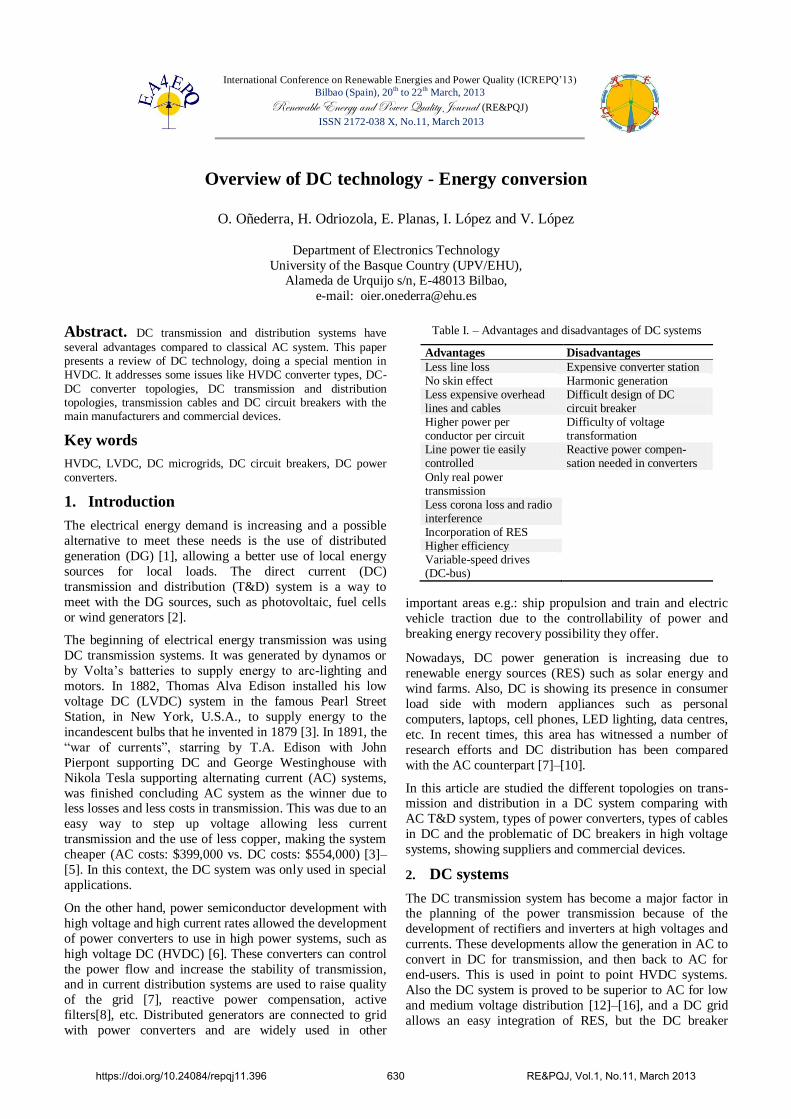
Table I. – Advantages and disadvantages of DC systems
Advantages Disadvantages
Less line loss Expensive converter station No skin effect Harmonic generation Less expensive overhead lines and cables
Difficult design of DC circuit breaker
Higher power per conductor per circuit
Difficulty of voltage transformation
Line power tie easily controlled
Reactive power compen-sation needed in converters
Only real power transmission
Less corona loss and radio interference
Incorporation of RES Higher efficiency Variable-speed drives (DC-bus)
important areas e.g.: ship propulsion and train and electric
vehicle traction due to the controllability of power and
breaking energy recovery possibility they offer.
Nowadays, DC power generation is increasing due to
renewable energy sources (RES) such as solar energy and
wind farms. Also, DC is showing its presence in consumer
load side with modern appliances such as personal
computers, laptops, cell phones, LED lighting, data centres,
etc. In recent times, this area has witnessed a number of
research efforts and DC distribution has been compared
with the AC counterpart [7]–[10].
In this article are studied the different topologies on trans-mission and distribution in a DC system comparing with
AC T&D system, types of power converters, types of cables
in DC and the problematic of DC breakers in high voltage
systems, showing suppliers and commercial devices.
2. DC systems
The DC transmission system has become a major factor in the planning of the power transmission because of the
development of rectifiers and inverters at high voltages and
currents. These developments allow the generation in AC to
convert in DC for transmission, and then back to AC for
end-users. This is used in point to point HVDC systems.
Also the DC system is proved to be superior to AC for low
and medium voltage distribution [12]–[16], and a DC grid
allows an easy integration of RES, but the DC breaker
https://doi.org/10.24084/repqj11.396 630 RE&PQJ, Vol.1, No.11, March 2013

Fig. 1. DC grid
technology is not enough developed to use in a big scale
nowadays [17].
In Figure 1 is shown a generalised DC grid system with
loads, RES and storage systems. The advantages and
disadvantages of using these types of systems are shown in
Table I, and in Table II some of DC grid projects are
exposed.
3. DC applications
Low power DC loads are widely spread in the houses, such
as PCs, portable electronic devices, LED light, etc. And
some low power generators, such as PV, are commonly
placed above the houses. So low power DC devices are very
common.
Following in a higher power level, in DC distribution field,
DG could be present and it may allow a lesser number of power conversion steps in a building for DC loads and local
generation comparing with the conventional AC system [2],
[13], [15], [16], [18]. But further development is required in
order to properly connect these new systems into the
existing power system which was not designed to support
active power generation at distribution level [19]. To meet
RES and the grid together, a microgrid is a suitable
interface [1]. The most microgrids around the world are
with AC system [20], but DC microgrids are being studied
and compared [21]–[25]. For example, in a photovoltaic
based DC microgrid, 15% of the energy is saved comparing with AC system [11]. Hybrid microgrids are also possible
[19], [26], helping both AC and DC system each other
making flexible and independent control and avoiding
overloads in the grid. The integration of the electric vehicle
(EV) may change the grids management, due to battery
storage system vehicles.
And finally, train traction, ship propulsion and HVDC are
the main high power DC applications [6], [9], [10]. The
HVDC transmission system is an economically suitable
Table III. – Types of DC cables
Main characteristic
Max
voltage Other
Mass-
Impregnated
Cable
Oil and resin
impregnated paper for
insulation.
600kV Unlimited length. Most
used in HVDC. Up to
2000MW.
Oil-Filled
Cable
Low viscosity oil
impregnated paper for
insulation. Duct to
permit oil flow.
600kV 100km length limit.
XLPE Cross-linked
polyethylene as
insulator.
500kV Unsuitable with LCC.
Up to 1000MW.
Lapped
Thin Film
Insulation
Lapped non
impregnated thin PP
film as insulator.
250kV Up to 250MW capacity.
HTS Cable Superconductor. Duct
to permit liquid
nitrogen flow.
275kV Short distances (100m
to 6km).
Table IV. – HVDC cable main suppliers
Manufacturer Main location Manufacturer Main location
ABB Sweeden Brugg Cables Switzerland
Nexans Norway 4s Products USA
Prysmian Italy General Cable USA
Viscas Japan Ericsson Sweeden
Borealis Denmark Siemens Germany
KEPCO Korea NKT cables Denmark
AMSC USA Furukawa Japan
Europacable Brussels Cabelte Portugal
LS Cable &
System
Korea BPP-Tech UK
alternative [27] to classical HVAC system. The break-even
distance for an economical advantage between AC and DC system is 50 km in cables and 800 km in overhead lines
[28]. And it also solves line length limit of HVAC due to
voltage stability [14], [29] and can be more efficient in
offshore power applications, resource diversification and
power line congestion relief [29].
A. HVDC cables
Underground cables for HVDC technology have been in
commercial use since the 1950’s. Nowadays, HVDC underground cables can carry medium and high power (100
MW up to 1 GW) over distances above 50 km, and has
mainly been used in submarine applications. These cables
are beginning to be used also for on-shore transmission
projects. As higher power loads need to be transported over
long distances across land, more and more thinking goes
into creating HVDC a long distance overlay net. HVDC
underground cables can safely transport high power loads
over long distances with minimal losses. In addition to this
transport efficiency, only a limited number of cables are
required, hence allowing narrow trenches. HVDC underground cables are compatible with HVDC overhead
technology and can be combined in sensitive areas. In Table
III are listed the types of DC cables with main
characteristics and in Table IV the main suppliers.
B. DC power converters
As power converters are transformers for a DC system, they
are used in a widespread applications. In a DC distribution
system are used to control only voltage for stability, but if in
the system are some converters, this control is not a so easy
tasks. These converters have been studied for ship
propulsion [9], [30], International Space Station, [31], [32],
https://doi.org/10.24084/repqj11.396 631 RE&PQJ, Vol.1, No.11, March 2013

Table V. – HVDC LCC and HVDC VSC comparison
HVDC LCC HVDC VSC
Maturity of technology Mature Developing
Valves Thyristor IGBT
Commutation failure Can occur Does not occur
Minimum DC power 5% to 10% of rated
power
No minimum value
Reactive power
exchange
with AC system
50% of active
power transmitted
Independent control of
active and reactive
power
Reactive compensation Required Not required
AC harmonic filters Switchable filters
required
Less filtering required,
not switchable
Converter
transformers
Special design
required
Conventional
transformer can be used
Reversal of power flow DC voltage polarity
reversal required
Controllable in both
directions, no reversal
of DC voltage polarity
required
Converter station foot-
print (pu)
1 0.4
Converter losses (per
converter end)
0.5% to 1% of
transmitted power
1% to 2% of
transmitted power
DC voltage Up to 800kV
available
Up to 350kV available
Power limit Up to 8GW
available
Up to 1GW available
Needed minimum
transmitted power
5 to 10% of rated
power
Can be zero
Fig. 2. HVDC converter topologies
electric vehicles, [33], [34], etc. Power converters are also
used in transmission of HVDC technology, and there are
two types: Line Commutated Converter (LCC) and Voltage
Source Converter (VSC). These are used to convert between AC and DC. Both technologies are compared in Table V.
Converters for HVDC systems have been mainly built by
using high voltage and high current rated power
semiconductors, but VSC system allows other topologies
due to the devices controls and these converters are not
limited only for transmission: most HVDC Light
installations (Figure 2b) built until 2012 use pulse width
Fig. 3. Classical multilevel converter topologies
modulation for in an ultra-high-voltage motor drive, but the
most recent installations, along with HVDC PLUS (Power
Link Universal System) (Figure 2c) and HVDC MaxSine
(Figure 2d), are based on variants of a converter called a
modular multilevel converter (MMC) [35]–[37]. Main
manufacturers of HVDC converters are ABB, Siemens,
Alstom, Areva and TMEIC GE.
Multilevel inverters can be used to interface lower voltage
DC energy storage or source devices with the grid. They
consist of power modules that are stacked together to
produce required high utility level voltages. One of the most
versatile topologies is the cascade multilevel inverter
(Figure 3c). In fact, multilevel converter technology started
with the introduction of the multilevel stepped waveform
concept with a series-connected H-bridge, which is also
known as cascaded H-bridge converter [38]. This topology eliminates the need for single high-voltage power switches
and diodes that do not exist in the utility voltage levels.
They also eliminate the need for connecting lower voltage
power devices and switches in series and parallel, reducing
the problems and extra circuitry associated with current and
voltage sharing. These converters have the advantage that
they allow the harmonic filtering equipment to be reduced
or eliminated altogether [39]–[41]. Classical multilevel
converters are shown in Figure 3.
DC distribution voltage levels are lower than in
transmission, so the devices of the power converters do not need to be so high rated in voltage or current. DC
generation (photovoltaic, fuel cells) and loads (data centres,
portable devices) are increasing in number, so a DC
distribution system may be useful because it could avoid
AC-DC conversions, increasing the whole system’s
efficiency [22]. So to meet voltage levels in DC systems,
DC-DC converters have to be used. Mainly they are
classified as isolated and non-isolated converters.
The non-isolated DC-DC converters (Figure 4) type is
generally used where the voltage needs to be stepped up or
down by a relatively small ratio (less than 4:1 [42]) and
https://doi.org/10.24084/repqj11.396 632 RE&PQJ, Vol.1, No.11, March 2013

Fig. 4. Non-isolated DC-DC converters
Table VI. – High-frequency power transformer core materials: 1-Amorphous, 2-Nanocrystalline, 3-Silicon steel
Group Series
Sat.
flux
(T)
Sp.
losses
(kW/kg)
Manufacturer
1
Microlite (2605SA1) 1.56 1.5 Metglass
Powerlite (2605SA1) 1.56 0.6 Metglass
Namglass 1.59 0.34 Magmet
Vitrovac (6030F) 0.82 0.19 VAC
2
Finemet (FT-3M) 1.23 0.14 Hitachi
Vitroperm (500F) 1.2 0.07 VAC
Nanoperm 1.2 0.04 Magnetec
Namglass 4 1.23 0.04 Magmet
3 Arnon 7 (3-6% Si, Fe) 1.53 1.6 Arnold
Arnon 5 (3-6% Si, Fe) 1.48 1.06 Arnold
when there is no problem with the output and input having
no dielectric isolation. These types of converters are simpler
than isolated ones and can achieve better efficiency. There
are five main types of converters in this non-isolated group,
usually called the buck, boost, buck-boost, Ćuk and SEPIC
(single ended primary inductor converter) (Figures 4a-4g).
These type of converters are mainly used in low power, but
to manage higher powers a multiphase current interleaving
topology can be used (Figure 4h) [43].
The isolation of DC-DC converters is done by a
transformer, so they need a variation of current flow to
make them work and this is done by switching devices.
These type of converters use a DC source to convert in AC
to attack the transformer, followed by the rectifying step to
deliver power in DC. There are many types of converters in
this group. The main structures of converting DC to AC are
shown in Figures 5a-5c, and to rectify the power from the
transformer the structures are Figures 5d-5f. Other classical isolated converters are flyback (Figure 5g) and forward
(Figure 5g). Due to the control of the AC signal generation,
high frequency signals are generated to attack a high
frequency transformers, because high frequency
transformers are lighter, smaller and more efficient. The
Figure 5i shows a dual active three-phase bridge (DAB) as
an example of polyphasic converter for higher power
conversion.
Fig. 5. Isolated DC-DC converters
High frequency transformers use magnetically soft cores
(Table VI). These cores are called soft because they have
low coercitivity, so they permit high variations of magnetic
flux with low losses [44]–[47]. This high variation of
magnetic flux is translated to a high modulation frequency with low losses, and so, a smaller volume and weight
comparing to conventional 50=60 Hz transformers.
C. DC transmission topologies
The development of the earliest power converters, which al-
lowed conversions between AC and DC, increased the
interest of DC transmission. So some DC transmission
topologies were developed [17], [29], [48]–[52], and in
Figure 6 are resumed the architectures of these transmission and distribution systems. Monopolar system: one conductor with ground or metallic
return path (Figures 6a and 6b)
Bipolar system: two conductors with opposite polarization
using a converter for each conductor. A neutral metallic return can be used, allowing a conversion of AC three phase grid into a bipolar DC system (Figures 6c and 6d)
Homopolar system: two conductors with same polarization,
returning through ground or a metallic path (Figure 6e). Less costs in isolation than bipolar
Tripolar system: same as a bipolar system, but adding a bidirectional converter for the third conductor (Figure
6f). It changes the neutral conductor by an active
conductor. It presents higher transmission capacity than
bipolar, so it’s a more efficient system to convert AC
grid system to DC system. There are no tripole systems
in operation yet
Back-to-back system: to connect two AC systems
asynchronously by a DC link. Also allows connection
between different frequency AC systems (Figure 6g)
Multi-terminal system: three or more converters in
series, parallel or mixed (Figure 6f). Used in wind farms
https://doi.org/10.24084/repqj11.396 633 RE&PQJ, Vol.1, No.11, March 2013

Fig. 6. DC transmission and distribution system architectures
Table VII. – Types of DC circuit breakers depending on used technology
MRTB Solid State
Switch CB
Fast
Switch
Solid State
CB without
auxiliary
circuit
Arc/Power
electronics
Arc
chamber
Arc
chamber+PE
PE PE
Development
needed
None Synchronous
switch,
capacitor
load circuit
New
concept
New
concept
Smallest
break time
27 ms to
41 ms
27 ms 2 ms 0.1 ms
On-state
losses
<1 m <1 m <100 m <1
Max
breaking
current
4 kA 5 kA 10 kA 10 kA
Complexity Low Medium High High
D. DC circuit breakers
The protection from damage caused by overload or short-
circuit is done by circuit breakers (CB), but the main difference between requirements on AC and DC breakers is
that in DC system is no natural current zero crossing, which
is the main reason of the difficulty of the design of direct
current CBs [53].
These circuit breakers are classified by used technology in
Table VII: metallic return transfer breaker (MRTB), solid
state switch circuit breaker, fast switch and solid state
circuit breaker without auxiliary circuit. Main DC circuit
breaker suppliers are shown in Table VIII.
Recently, ABB has developed a HVDC circuit breaker. It combines very fast mechanics with power electronics, and
will be capable of interrupting power flows equivalent to
the output of a large power station within 5 ms [54].
Table VIII presents the main DC circuit breaker
manufacturers and the voltage and current rates of
commercial breakers.
4. Conclusions
DC technology is mature in transmission, and R&D
continues for different types of devices as converters and
cables. But DC distribution and DC microgrids, are not so
integrated in the system as HVDC transmission does. One
of the most important reasons is that the protection with
circuit breakers is not mature enough to protect a DC
system, so for the most of DC application nowadays are
locally rectified from the AC grid. The development of DC
circuit breakers could be the key to continue with DC
distribution and microgrid development and further
installations. Meanwhile, more efficient converter
topologies and control strategies are coming across in all
power levels, obtaining more efficiently energy from
renewable energy sources.
5. Acknowledgments
This work has been carried out inside the Research and
Education Unit UFI11/16 of the UPV/EHU and supported
by the Department of Education, Universities and Research of the Basque Government within the fund for research
groups of the Basque university system IT394-10 and by the
University of the Basque Country.
References
[1] E. Planas, A. G. de Muro, J. Andreu, I. Kortabarria, and I. M. de
Alegría, ―General aspects, hierarchical controls and droop methods in
microgrids: A review,‖ Renewable and Sustainable Energy Reviews,
vol. 17, no. 0, pp. 147 – 159, 2013.
[2] F. Dastgeer and A. Kalam, ―Efficiency comparison of DC and AC
distribution systems for distributed generation,‖ in Proc. of
Australasian Universities Power Engineering Conference (AUPEC),
September 2009, pp. 1 – 5.
[3] B. A. Thomas, I. L. Azevedo, and G. Morgan, ―Edison revisited:
Should we use DC circuits for lighting in commercial buildings?‖
Energy Policy, vol. 45, no. 0, pp. 399 – 411, June 2012.
[4] C. Sulzberger, ―Triumph of AC 1 - from pearl street to niagara,‖ IEEE
Power and Energy Magazine, vol. 99, no. 3, pp. 64 – 67, May/June
2003.
[5] ——, ―Triumph of AC 2 - the battle of the currents,‖ IEEE Power and
Energy Magazine, vol. 1, no. 4, pp. 70 – 73, July/August 2003.
[6] I. M. de Alegría, J. L. Martín, I. Kortabarria, J. Andreu, and P. I. Ereño,
―Transmission alternatives for offshore electrical power,‖ Renewable
and Sustainable Energy Reviews, vol. 13, no. 5, pp. 1027 – 1038, June
2009.
[7] T. Ise, ―Power electronics toward the era of distributed generations,‖ in
Proc. of IEEE Workshop on Control and Modeling for Power
Electronics (COMPEL), June 2012, pp. 1 – 8.
[8] R. K. Antar, B. M. Saied, R. A. Khalil, and G. A. Putrus, ―HVDC link
power quality improvement using a modified active power filter,‖ in
Proc. of International Universities Power Engineering Conference
(UPEC), September 2012, pp. 1 – 5.
[9] S. Chen, J. Daozhuo, L. Wentao, and W. Yufen, ―An overview of the
application of DC zonal distribution system in shipboard integrated
power system,‖ in Proc. of International Conference on Digital
Manufacturing and Automation (ICDMA), August 2012, pp. 206 –
209.
[10] J. Apsley, A. Villasenor, M. Barnes, A. Smith, S. Williamson, J.
Schud-debeurs, P. Norman, C. Booth, G. Burt, and J. McDonald,
―Propulsion drive models for full electric marine propulsion systems,‖
in Proc. of IEEE International Electric Machines Drives Conference
(IEMDC), vol. 1, May 2007, pp. 118 – 123.
[11] H. Kakigano, M. Nomura, and T. Ise, ―Loss evaluation of DC
distribution for residential houses compared with AC system,‖ in Proc.
of International Power Electronics Conference (IPEC), June 2010, pp.
480 – 486.
[12] M. Amin, Y. Arafat, S. Lundberg, and S. Mangold, ―Low voltage DC
distribution system compared with 230 V AC,‖ in Proc. of IEEE
https://doi.org/10.24084/repqj11.396 634 RE&PQJ, Vol.1, No.11, March 2013

Electrical Power and Energy Conference (EPEC), October 2011, pp.
340 – 345.
[13] M. Starke, L. Tolbert, and B. Ozpineci, ―AC vs. DC distribution: A
loss comparison,‖ in Proc. of IEEE PES Transmission and Distribution
Conference and Exposition, April 2008, pp. 1 – 7.
[14] K. Meah and S. Ula, ―Comparative evaluation of HVDC and HVAC
transmission systems,‖ in Proc. of IEEE Power Engineering Society
General Meeting, June 2007, pp. 1 – 5.
[15] D. Hammerstrom, ―AC versus DC distribution systems - did we get it
right?‖ in Proc. of IEEE Power Engineering Society General Meeting
(PESGM), June 2007, pp. 1 – 5.
[16] D. Nilsson and A. Sannino, ―Efficiency analysis of low -and medium-
voltage DC distribution systems,‖ in Proc. of IEEE Power Engineering
Society General Meeting (PESGM), June 2004, pp. 2315 – 2321.
[17] M. Saeedifard, M. Graovac, R. Dias, and R. Iravani, ―DC power
systems: Challenges and opportunities,‖ in Proc. of IEEE Power and
Energy Society General Meeting (PESGM), July 2010, pp. 1 – 7.
[18] M. Starke, F. Li, L. Tolbert, and B. Ozpineci, ―AC vs. DC
distribution: Maximum transfer capability,‖ in Proc. of IEEE Power
and Energy Society General Meeting, July 2008, pp. 1 – 6.
[19] Z. Jiang and X. Yu, ―Hybrid DC -and AC - linked microgrids:
Towards integration of distributed energy resources,‖ in Proc. of IEEE
Energy 2030 Conference, November 2008, pp. 1 – 8.
[20] N. Lidula and A. Rajapakse, ―Microgrids research: A review of
experimental microgrids and test systems,‖ Renewable and Sustainable
Energy Reviews, vol. 15, no. 1, pp. 186 – 202, January 2011.
[21] D. Salomonsson, L. Soder, and A. Sannino, ―Protection of low-
voltage DC microgrids,‖ IEEE Transactions on Power Delivery, vol.
24, no. 3, pp. 1045 – 1053, July 2009.
[22] D. Becker and B. Sonnenberg, ―DC microgrids in buildings and data
centers,‖ in Proc. of IEEE International Telecommunications Energy
Conference (INTELEC), October 2011, pp. 1 – 7.
[23] S. Ali, M. Babar, S. Maqbool, and E. Al Ammar, ―Comparative
analysis of AC DC microgrids for the saudi arabian distribution
system,‖ in Proc. of IEEE PES Transmission and Distribution
Conference and Exposition, May 2012, pp. 1 – 8.
[24] H. Kakigano, Y. Miura, T. Ise, T. Momose, and H. Hayakawa,
―Fundamental characteristics of DC microgrid for residential houses
with cogeneration system in each house,‖ in Proc. of IEEE Power and
Energy Society General Meeting (PESGM), July 2008, pp. 1 – 8.
[25] M. Heath, G. Vosters, G. Parker, W. Weaver, D. Wilson, and R.
Robinett, ―DC microgrid optimal storage distribution using a
conductance and energy state modeling approach,‖ in Proc. of
International Symposium on Power Electronics, Electrical Drives,
Automation and Motion (SPEEDAM), June 2012, pp. 170 – 174.
[26] P. C. Loh, D. Li, Y. K. Chai, and F. Blaabjerg, ―Hybrid AC-DC
microgrids with energy storages and progressive energy flow tuning,‖
in Proc. of International Power Electronics and Motion Control
Conference (IPEMC), vol. 1, June 2012, pp. 120 – 127.
[27] T. Hammons, V. Lescale, K. Uecker, M. Haeusler, D. Retzmann, K.
Staschus, and S. Lepy, ―State of the art in ultrahigh-voltage
transmission,‖ Proceedings of the IEEE, vol. 100, no. 2, pp. 360 – 390,
February 2012.
[28] D. M. Larruskain, I. Zamora, O. Abarrategui, and Z. Aginako, ―Con-
version of AC distribution lines into DC lines to upgrade transmission
capacity,‖ Electric Power Systems Research, vol. 81, no. 7, pp. 1341 –
1348, July 2011.
[29] M. H. Okba, M. H. Saied, M. Z. Mostafa, and T. M. Abdel Moneim,
―High voltage direct current transmission - a review, part i,‖ in Proc. of
IEEE Energytech, May 2012, pp. 1 – 7.
[30] J. LeSage, R. Longoria, and W. Shutt, ―Power system stability
analysis of synthesized complex impedance loads on an electric ship,‖
in Proc. of IEEE Electric Ship Technologies Symposium (ESTS), April
2011, pp. 34 – 37.
[31] J. Ly and C. Truong, ―Stability analysis of the international space
station electrical power system,‖ in Proc. of IEEE International
Conference on Control Applications, vol. 1, August 1999, pp. 628 –
633.
[32] A. Emadi, J. Johnson, and M. Ehsani, ―Stability analysis of large DC
solid-state power systems for space,‖ IEEE Aerospace and Electronic
Systems Magazine, vol. 15, no. 2, pp. 25 – 30, February 2000.
[33] E. Jamshidpour, B. Nahid Mobarakeh, P. Poure, S. Pierfederici, and S.
Saadate, ―Distributed stabilization in DC hybrid power systems,‖ in
Proc. of IEEE Vehicle Power and Propulsion Conference (VPPC),
September 2011, pp. 1 – 6.
[34] P. Magne, B. Nahid Mobarakeh, and S. Pierfederici, ―A general active
stabilizer for a multi-loads DC-power network,‖ in Proc. of IEEE
Industry Applications Society (IAS), October 2011, pp. 1 – 8.
[35] F. Khan and L. Tolbert, ―A multilevel modular capacitor-clamped
DC-DC converter,‖ IEEE Transactions on Industry Applications, vol.
43, no. 6, pp. 1628 – 1638, November/December 2007.
[36] R. Marquardt, ―Modular multilevel converter: An universal concept
for HVDC-networks and extended DC-bus-applications,‖ in Proc. of
International Power Electronics Conference (IPEC), June 2010, pp. 502
– 507.
[37] L. Yang, C. Zhao, and X. Yang, ―Loss calculation method of modular
multilevel HVDC converters,‖ in Proc. of IEEE Electrical Power and
Energy Conference (EPEC), October 2011, pp. 97 – 101.
[38] F. Peng, W. Qian, and D. Cao, ―Recent advances in multilevel
converter/inverter topologies and applications,‖ in Proc. of
International Power Electronics Conference (IPEC), June 2010, pp. 492
– 501.
[39] S. Khomfoi, N. Praisuwanna, and L. Tolbert, ―A hybrid cascaded
multilevel inverter application for renewable energy resources
including a reconfiguration technique,‖ in Proc. of IEEE Energy
Conversion Congress and Exposition (ECCE), September 2010, pp.
3998 – 4005.
[40] L. Franquelo, J. Rodriguez, J. Leon, S. Kouro, R. Portillo, and M.
Prats, ―The age of multilevel converters arrives,‖ IEEE Industrial
Electronics Magazine, vol. 2, no. 2, pp. 28 – 39, June 2008.
[41] J. Rodriguez, J. S. Lai, and F. Z. Peng, ―Multilevel inverters: a survey
of topologies, controls, and applications,‖ IEEE Transactions on
Industrial Electronics, vol. 49, no. 4, pp. 724 – 738, August 2002.
[42] J. V. M. Monzer Al Sakka and H. Gualous, ―Dc/dc converters for
electric vehicles,‖ September 2011.
[43] P. Jose and N. Mohan, ―A novel bidirectional DC-DC converter with
ZVS and interleaving for dual voltage systems in automobiles,‖ in
Proc. of IEEE Industry Applications Society (IAS), vol. 2, October
2002, pp. 1311 – 1314.
[44] G. Ortiz, J. Biela, and J. Kolar, ―Optimized design of medium
frequency transformers with high isolation requirements,‖ in Proc. of
Industrial Electronics Society Conferende (IECON), November 2010,
pp. 631 – 638.
[45] R. Hasegawa and D. Azuma, ―Impacts of amorphous metal-based
transformers on energy efficiency and environment,‖ Journal of
Magnetism and Magnetic Materials, vol. 320, no. 20, pp. 2451 – 2456,
October 2008.
[46] M. Carlen, D. Xu, J. Clausen, T. Nunn, V. R. Ramanan, and D. M.
Getson, ―Ultra high efficiency distribution transformers,‖ in Proc. of
IEEE PES Transmission and Distribution Conference and Exposition,
April 2010, pp. 1 – 7.
[47] T. Steinmetz, B. Cranganu Cretu, and J. Smajic, ―Investigations of no-
load and load losses in amorphous core dry-type transformers,‖ in Proc.
of International Conference on Electrical Machines (ICEM), September
2010, pp. 1 – 6.
[48] J. Rekola and H. Tuusa, ―Comparison of line and load converter
topologies in a bipolar LVDC distribution,‖ in Proc. of European
Conference on Power Electronics and Applications (EPE), September
2011, pp. 1– 10.
[49] L. Barthold and H. Hartmut, ―Conversion of AC transmission lines to
HVDC using current modulation,‖ in Proc. of IEEE Power Engineering
Society Inaugural Conference and Exposition, July 2005, pp. 26 – 32.
[50] L. Barthold, ―Technical and economic aspects of tripole HVDC,‖ in
Proc. of International Conference on Power System Technology
(PowerCon), October 2006, pp. 1 – 6.
[51] L. Barthold, H. Clark, and D. Woodford, ―Principles and applications
of current-modulated HVDC transmission systems,‖ in Proc. of IEEE
PES Transmission and Distribution Conference and Exhibition, May
2006, pp. 1429 – 1435.
[52] A. A. Edris, L. Barthold, D. Douglas, W. Litzenberger, and D.
Woodford, ―Upgrading AC transmission to DC for maximum power
transfer capacity,‖ in Proc. of International Middle - East Power
System Conference (MEPCON), March 2008, pp. 44 – 49.
[53] C. Franck, ―HVDC circuit breakers: A review identifying future
research needs,‖ IEEE Transactions on Power Delivery, vol. 26, no. 2,
pp. 998 – 1007, April 2011.
[54] ABB, ―ABB solves 100-year-old electrical puzzle -new technology to
enable future DC grid,‖ November 2012. [Online]. Available:
http://www.abb.com/cawp/seitp202/65df338284e41b3dc1257aae0045b
7de.aspx
https://doi.org/10.24084/repqj11.396 635 RE&PQJ, Vol.1, No.11, March 2013