overview of computer-aided engineering of batteries and ... · overview of computer-aided...
TRANSCRIPT

NREL is a national laboratory of the U.S. Department of Energy, Office of Energy Efficiency and Renewable Energy, operated by the Alliance for Sustainable Energy, LLC.
Overview of Computer-Aided Engineering of Batteries and
Introduction to Multi-Scale, Multi-Dimensional Modeling of Li-Ion Batteries
P.I. - Ahmad A. Pesaran, G.-H. Kim, K. Smith, S. Santhanagopalan, K.-J. Lee National Renewable Energy Laboratory
May 15, 2012
NREL/PR-5400-54425 Project ID #ES117
This presentation does not contain any proprietary, confidential, or otherwise restricted information.
Vehicle Technologies Program (VTP) Annual Merit Review (AMR) May 14-18 2012 Washington, DC

2
Overview
Project Start Date: April 2010 Project End Date: September 2014 Percent Complete: 30%
• Cost and life • Performance and safety • Lack of validated computer- aided
engineering tools for accelerating battery development cycle
Total Project Funding: DOE Share: $9 M Contractor Share: $7 M Funding Received in FY11: $3.5 M ($2.5 M for subcontracts) Funding for FY12: $1.0 M expected
Timeline
Budget
Barriers
• Project lead: NREL • Oak Ridge National Laboratory (ORNL),
Idaho National Laboratory (INL), Colorado School of Mines (CSM)
• EC Power/Penn State Univ (PSU)/ Ford/Johnson Controls, Inc. (JCI)
• General Motors (GM)/ANSYS/ESim • CD-adapco/Battery
Design/JCI/A123Systems
Partners
Funding provided by Dave Howell of the DOE Vehicle Technologies Program. The activity is managed by Brian Cunningham of Vehicle Technologies.
This presentation covers two related topics: Overview of the CAEBAT Project and NREL’s battery Multi-Scale Multi-Dimensional (MSMD) modeling work under CAEBAT

3
Computer Aided Engineering for Electric Drive Vehicle Batteries (CAEBAT)
• Simulation and computer-aided engineering (CAE) tools are widely used to speed up the research and development cycle and reduce the number of build-and-break steps, particularly in the automotive industry.
• There has been a need to have several user-friendly, 3D, fully integrated, and validated CAE software tools for the battery community.
• National laboratories, industry, and universities have been developing models on cost, life, performance (electro-thermal, electrochemical) and abuse to simulate lithium-ion batteries.
• Realizing the need, DOE’s Vehicle Technologies Program initiated a project in April 2010 to bring together these battery models to develop CAEBAT tools for designing batteries.
Battery Pack Level Models
Performance
Electrochemical & Material StressMaterial Stress
Current & Heat Transport
ElectrodeLevel Models
CellLevel Models
MaterialLevel Models
Fluid Dynamics
First Principles
Power Demand
Source: VARTA
Battery Pack Design Software
Relevance

4
Objectives
• The overall objective of the CAEBAT project is to incorporate existing and new models into “validated” battery design suites/tools.
• Objectives of the past year (March 2011 to March 2012) were to: – Complete negotiations and enter into subcontract agreements with
the three teams competitively selected in 2010. – Subcontractors to start technical work. – NREL to have kickoff and quarterly meetings with subcontractors to
monitor their technical performance and progress. – Continue developing NREL’s multi-physics electrochemical lithium-
ion battery (MSMD) model and document the approach and results in a peer-reviewed journal.

5
Relevance
• CAEBAT objectives are relevant to the Vehicle Technologies Program’s targets of:
– Plug-in hybrid electric vehicle (PHEV) battery costs of $300/kWh and life of 15 years by 2014
– PHEV battery costs of $270/kWh and life of 10+ years by 2017
– Electric vehicle battery costs of $150/kWh and life of 10 years by 2020
• The impact of this project when CAEBAT tools are made available could be significant:
– Shorten design cycles and optimization of batteries – Simultaneously address the barriers of cost, performance,
life, and safety of lithium-ion with quantitative tools

6
Milestones
Date Milestone or Go/No-Go Decision
Status
June 2011 Negotiate and place subcontracts with CAEBAT RFP awardees
Completed
July 2011 Progress review on the work for the CAEBAT-NREL program
Completed
September 2011 Document NREL’s MSMD modeling approach in a peer-reviewed journal
Completed
July 2012 Document latest NREL battery models, solution methods, and codes developed under CAEBAT
On Track
September 2012 Technical review of the three CAEBAT subcontracts
On Track
7
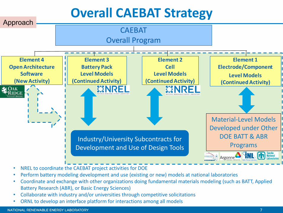
Overall CAEBAT Strategy
• NREL to coordinate the CAEBAT project activities for DOE • Perform battery modeling development and use (existing or new) models at national laboratories • Coordinate and exchange with other organizations doing fundamental materials modeling (such as BATT, Applied
Battery Research (ABR), or Basic Energy Sciences) • Collaborate with industry and/or universities through competitive solicitations • ORNL to develop an interface platform for interactions among all models
CAEBATOverall Program
Element 4Open Architecture
Software(New Activity)
Element 3Battery Pack Level Models
(Continued Activity)
Element 1Electrode/Component
Level Models(Continued Activity)
Element 2Cell
Level Models(Continued Activity)
Material-Level Models Developed under Other
DOE BATT & ABR Programs
Industry/University Subcontracts for Development and Use of Design Tools
Approach

8
CAEBAT and MSMD Approach • Develop CAEBAT software tools with industry
– Background from FY 10 and Fall of FY11 o We initiated a competitive process (RFP) to solicit cost-shared
proposals from the industry o After a comprehensive process, three teams were selected to
develop CAEBAT software tools – Approach in 2011
o Completed negotiations and entered into subcontract agreements with the three selected teams
o Initiated CAEBAT projects and monitor technical performance and progress
o Collaborated with ORNL on Open Architecture Software • Perform in-house R&D to enhance and further develop NREL’s
existing electrochemical-thermal (MSMD) models for use by CAEBAT participants
9
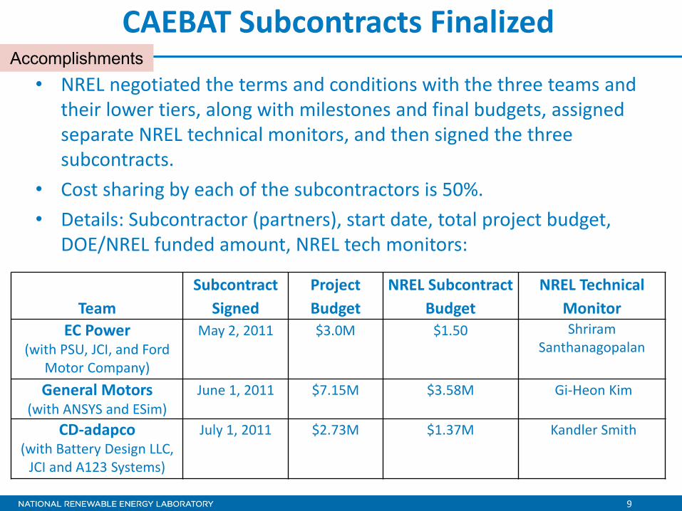
• NREL negotiated the terms and conditions with the three teams and their lower tiers, along with milestones and final budgets, assigned separate NREL technical monitors, and then signed the three subcontracts.
• Cost sharing by each of the subcontractors is 50%. • Details: Subcontractor (partners), start date, total project budget,
DOE/NREL funded amount, NREL tech monitors:
CAEBAT Subcontracts Finalized Accomplishments
Team Subcontract
Signed Project Budget
NREL Subcontract Budget
NREL Technical Monitor
EC Power (with PSU, JCI, and Ford
Motor Company)
May 2, 2011 $3.0M $1.50 Shriram Santhanagopalan
General Motors (with ANSYS and ESim)
June 1, 2011 $7.15M $3.58M Gi-Heon Kim
CD-adapco (with Battery Design LLC,
JCI and A123 Systems)
July 1, 2011 $2.73M $1.37M Kandler Smith
10
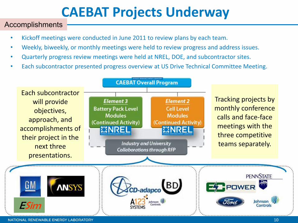
CAEBAT Projects Underway • Kickoff meetings were conducted in June 2011 to review plans by each team. • Weekly, biweekly, or monthly meetings were held to review progress and address issues. • Quarterly progress review meetings were held at NREL, DOE, and subcontractor sites. • Each subcontractor presented progress overview at US Drive Technical Committee Meeting.
Each subcontractor will provide objectives,
approach, and accomplishments of their project in the
next three presentations.
ESim
Accomplishments
Tracking projects by monthly conference calls and face-face meetings with the three competitive teams separately.

11
Coordinating on Open Architecture Software
• Interacted with ORNL on the Open Architecture Software element of CAEBAT “that facilitates integrating battery modeling components within an open architecture.” – Participated in regular
conference calls – Participated at ORNL’s kickoff
meeting – Provided MSMD model for
testing the integration approach – Provided suggestions for
standardized input data and battery state
from ORNL presentation by S. Pannala, 2012 AMR
ORNL will provide the objectives, approach, and accomplishments of this project in AMR
2012 presentation ES121
Accomplishments

12
NREL Battery Modeling Under CAEBAT
Paper published in Journal of the Electrochemical Society entitled “Multi-Domain Modeling of Lithium-Ion Batteries
Encompassing Multi-Physics in Varied Length Scales,” describing approach and results of NREL MSMD model
Volume 158, Issue 8, pp. A955-A969 (17 June 2011)

13
Commonly Used Porous Electrode Model
Charge Conservation
( ) Ues −−= φφη
( ) qTktTcp ′′′+∇⋅∇=∂∂ρ
• Pioneered by John Newman’s group at the University of Berkeley (Doyle, Fuller, and Newman 1993)
• Captures lithium diffusion dynamics and charge transfer kinetics
• Predicts current/voltage response of a battery • Provides design guide for thermodynamics, kinetics,
and transport across electrodes
eeeffDee
effss
effes
Li cTUTUjq φκφφκφφσφφ ∇⋅∇+∇⋅∇+∇⋅∇+
∂∂
+−−=′′′ ln
Charge Transfer Kinetics at Reaction Sites
Species Conservation
Energy Conservation • Difficult to apply in large-format batteries where heat and electron current transport critically affect the battery responses
r
Background

14
Published NREL’s MSMD Model Framework
• Introduces multiple computational domains for corresponding length-scale physics
• Decouples LIB geometries into separate computation domains
• Couples physics using the predefined inter-domain information exchange
• Selectively resolves higher spatial resolution for smaller characteristic length-scale physics
• Achieves high computational efficiency • Provides flexible & expandable modularized
framework
Kim et al., “Multi-Domain Modeling of Lithium-Ion Batteries Encompassing Multi-Physics in Varied Length Scales,” J. Electrochem. Soc., 2011, Vol. 158, No. 8, pp. A955–A969
Through the multi-year effort supported by DOE, NREL has developed a modeling framework for predictive computer simulation of lithium-ion batteries (LIBs) known as the Multi-Scale Multi-Dimensional (MSMD) model that addresses the interplay among the physics in varied scales.
Accomplishments

15
MSMD Segregates Time & Length Scales
• Self-balancing nature allows a continuum approach with thermodynamic representation for sub-domain systems
• Time-scale differences in kinetic/dynamic transport processes conducive to segregation into sub-domain systems
σcc
σce
Electronic conductivity is much higher in metal current collectors than in a composite electrode matrix
e.g., σce<<σcc
Ds De
Lithium transport is much faster in liquid electrolyte than in solid particles
e.g., Ds<<De
Kim et al., “Multi-Domain Modeling of Lithium-Ion Batteries Encompassing Multi-Physics in Varied Length Scales,” J. Electrochem. Soc., 2011, Vol. 158, No. 8, pp. A955–A969
Accomplishments

16
MSMD Decouples Geometry
Domain Invariant
Domain Average
Local information transfers from cell to electrode sandwich and to particles
Averaged parameters transfer back from particles to electrode sandwich and to the cell
Accomplishments

17
MSMD Decouples Geometry
Domain Invariant
Domain Invariant
Domain Average
Domain Average
Local information transfers from cell to electrode sandwich and to particles
Averaged parameters transfer back from particles to electrode sandwich and to the cell
Accomplishments

NATIONAL RENEWABLE ENERGY LABORATORY 18
MSMD Framework is Modularized
Electrode Domain Submodel Development Solution Models & Method/Algorithms
Particle Domain Submodel Development Solution Models & Method/Algorithms
Cell Domain Submodel Development Solution Models & Method/Algorithms
Modularized hierarchical architecture of the MSMD model allows independent development of submodels for physics captured in each domain
The modularized framework facilitates collaboration with experts across organizations.
1D Spherical particle model Finite Element
1D porous electrode model Reduced Order Approximation
Finite Volume – Linear superposition
3D Single potential pair continuum model
Accomplishments
Examples
Examples
Examples

NATIONAL RENEWABLE ENERGY LABORATORY 19
MSMD Framework is Modularized
Electrode Domain Submodel Development Solution Models & Method/Algorithms
Particle Domain Submodel Development Solution Models & Method/Algorithms
Cell Domain Submodel Development Solution Models & Method/Algorithms
Modularized hierarchical architecture of the MSMD model allows independent development of submodels for physics captured in each domain
The modularized framework facilitates collaboration with experts across organizations.
1D Spherical particle model Finite Element
1D porous electrode model Reduced Order Approximation
Finite Volume – Linear superposition
2D cylindrical particle model Reduced Order Method
3D Single potential pair continuum model
Finite Element Method
Finite Volume Method
3D wound potential pair continuum (WPPC) model
Accomplishments
Examples
Examples
Examples

20
Application of MSMD for Predicting Cell Behavior
Large Stacked Prismatic Cell
• SVM (state variable method)
• FV-LSM finite volume – linear
superposition methods
• SVM
• 1D spherical particle model
Submodel in the Particle Domain Submodel in the Electrode Domain Submodel in the Cell Domain
Submodel Choice Solution Method
• 1D porous electrode model
• 3D single potential-pair continuum model (SPPC)
Accomplishments

21
Predicted Non-Uniform Utilization in Prismatic Cells
Mid-size sedan PHEV10 US06
Kim et al., “Multi-Domain Modeling of Lithium-Ion Batteries Encompassing Multi-Physics in Varied Length Scales,” J. Electrochem. Soc., 2011, Vol. 158, No. 8, pp. A955–A969
Tab size
Accomplishments
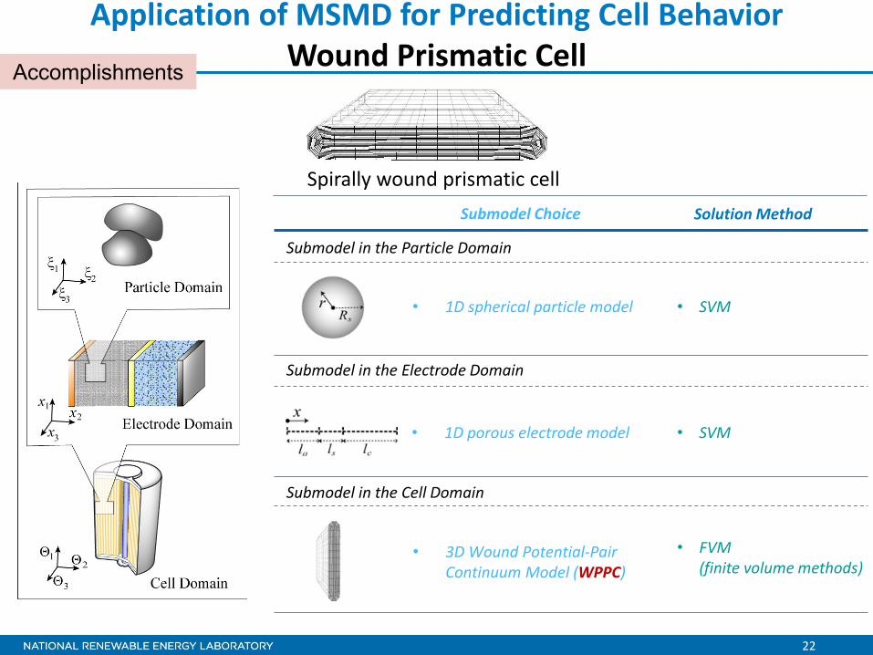
22
Application of MSMD for Predicting Cell Behavior Wound Prismatic Cell
• SVM
• FVM (finite volume methods)
• SVM
• 1D spherical particle model
Submodel in the Particle Domain Submodel in the Electrode Domain Submodel in the Cell Domain
Submodel Choice Solution Method
• 1D porous electrode model
• 3D Wound Potential-Pair Continuum Model (WPPC)
Accomplishments
Spirally wound prismatic cell

23
Response of a Wound Prismatic Cell
Model results after 500 sec at 4C discharge of 20-Ah cell with continuous tabs at surface (left images) and unrolled jelly roll (right images)
The simulation shows that non-uniform charge transfer current density and temperature are distributed around the bent radius
Accomplishments
Time is 500sec, Temp oC
0.5 1 1.5 2 2.50
0.15
3333.233.433.633.8
Time is 500sec, IpA
0.5 1 1.5 2 2.50
0.15
94.594.694.7
Temperature distribution
Reaction current density distribution

24
Thermal Response of Wound Cylindrical Cells
Temperature imbalance at 4C discharge
Continuous-tabs (CT) cell
Impact of electrical current transport design: • With higher number of tabs, current and
temperature distribution are more uniform
Accomplishments
K.-J. Lee, K. Smith, G.-H. Kim, “A Three-Dimensional Thermal-Electrochemical Coupled Model for Spirally Wound Large-Format Lithium-Ion Batteries,” presented at Space Power Workshop; Los Angeles, CA; April 18, 2011.

25
Collaboration and Coordination
ESim
• Coordination with other national labs under CAEBAT – ORNL (open architecture software) – INL (providing electrolyte properties to CD-adapco)
• Collaboration with CAEBAT subcontractors to develop battery CAE design tools – General Motors, ANSYS, ESim – CD-adapco, Battery Design, A123 Systems, and JCI – EC Power, Penn State U, JCI, and Ford
• Colorado School of Mines – Published a joint paper on integrated general chemistry solver for charge transfer and side reactions in Li-ion

26
Proposed Future Work • Collaborate with CAEBAT partners to develop CAEBAT tools • Continue enhancing MSMD modeling framework • Conduct experiments to validate NREL’s MSMD models • Work with others in using MSMD models • Collaborate with ORNL on implementing Open Architecture
Software • Review subcontractors’ plans with focus on validation of cell
and pack models • Key upcoming milestones:
– Document latest NREL battery model developments by publishing journal papers
– Compete technical review of the three CAEBAT subcontracts – Review 1st version of CAEBAT subcontractors’ tools for cells
• Work with collaborators and partners to promote the use of CAEBAT tools within the battery community

27
Publications and Presentations • K.-J. Lee, K. Smith, G.-H. Kim, “A Three-Dimensional Thermal-
Electrochemical Coupled Model for Spirally Wound Large-Format Lithium-Ion Batteries,” presented at Space Power Workshop; Los Angeles, CA; April 18, 2011.
• A.M. Colclasure, K.A. Smith, R.J. Kee, “Modeling Detailed Chemistry and Transport for Solid Electrolyte Interface (SEI) Films in Li-ion Batteries,” Electrochimica Acta. Vol. 58, 30 December 2011; pp. 33-43.
• G.-H. Kim, K. Smith, K.-J. Lee, S. Santhanagopalan, A. A. Pesaran, “Multi-Domain Modeling of Lithium-Ion Batteries Encompassing Multi-Physics in Varied Length Scales,” J. Electrochem. Soc., 2011, Vol. 158, No. 8, pp. A955–A969.
• A. A. Pesaran, G.-H. Kim, K. Smith, K.-J. Lee, and S. Santhanagopalan, “Computer-Aided Engineering of Batteries for Designing Better Li-Ion Batteries,” presented at the Advanced Automotive Battery Conference, Orlando, Florida; February 6-8, 2012.

28
Summary
• CAEBAT activity was initiated to develop battery computer-aided engineering tools to accelerate development of batteries for electric vehicles.
• CAEBAT activities at NREL consist of two parallel paths: o Working with industry to develop CAEBAT tools through cost-shared
subcontracts o NREL in-house electrochemical battery model development
• After a competitive process, NREL executed three subcontracts with three industry teams – a total of $14M with 50% cost share from industry – to develop the battery computer tools. o GM/ANSYS/Esim o CD-adapco/Battery Design/A123 Systems/JCI o EC Power/Pennsylvania State University/JCI/Ford
• NREL collaborated with ORNL on CAEBAT open architecture software. • NREL continued the development of its MSMD electrochemical/thermal
modeling and published papers (for stacked prismatic, wound cylindrical, and wound prismatic configurations).
• CAEBAT project is proceeding very well and according to plan.

Technical Back-Up Slides

30
Cell Domain Models • SPPC (Single Potential-Pair Continuum) model:
applicable to stack prismatic cells, tab-less wound cylindrical/(prismatic) cells:
• MPPC (Multi Potential-Pair Continuum) model: applicable to alternating stacked prismatic cells:
• WPPC (Wound Potential-Pair Continuum) model: applicable to spirally wound cylindrical/ (prismatic) cells:
• Lumped model: applicable to small cells
NREL’s Cell-Domain Models: Orthotropic Continuum Model
√
√
Discussed in this presentation
Wound cell with continuous tab

31
Electric Current Transport – Prismatic 4C discharge / Single-side cooling

32
Electric Current Transport – Prismatic 4C discharge / Single-side cooling

33
Electric Current Transport – Prismatic
0 110 135 215-100
-80
-60
-40
-20
0
φ e [m
V]
x [µm]
1C2C3C4C
4C discharge / Single-side cooling

34
Electric Current Transport – Prismatic
0 110 135 215-100
-80
-60
-40
-20
0
φ e [m
V]
x [µm]
1C2C3C4C
4C discharge / Single-side cooling bottom cooled top

35
Wound Cells (Cylindrical or Prismatic) • A pair of wide current collectors • Two electrode pairs • Cylindrical or prismatic cells
Stacking : Forming the first pair between inner electrodes
Winding : Forming the second pair between outer electrodes
Current collector
Current collector Separator
electrode
electrode Pairing Inner
Electrodes
Separator
electrode
electrode
Pairing Outer Electrodes
0 0.2 0.4 0.6 0.8 1 1.2 1.4 1.6 1.8 20
0.05
0.1
X [m]
]m[
Y
0 0.2 0.4 0.6 0.8 1 1.2 1.4 1.6 1.8 20
0.05
0.1
X [m]
]m[
Y Negative current collector
Positive current collector
Inner electrode pair
Outer electrode pair

36
WPPC (Wound Potential-Pair Continuum)
Separator Separator
Unit stratum/ finite cell volume
Applicable to flat wound prismatic cells

37
Kinetics Response – Wound Cylindrical Cell
Impact of electrical current transport design
Continuous-tabs (CT) cell
Accomplishments
K.-J. Lee, K. Smith, G.-H. Kim, “A Three-Dimensional Thermal-Electrochemical Coupled Model for Spirally Wound Large-Format Lithium-Ion Batteries,” presented at Space Power Workshop; Los Angeles, CA; April 18, 2011.