overview guide networks/ fieldbus
TRANSCRIPT

www.turck.com
Overview Guide
Networks/Fieldbus
Courtesy of Steven Engineering, Inc. ● 230 Ryan Way, South San Francisco, CA 94080-6370 ● General Inquiries: (800) 670-4183 ● www.stevenengineering.com

TURCK Inc. 3000 Campus Drive Minneapolis, MN 55441 Application Support: 1-800-544-7769 Fax: (763) 553-0708 www.turck.com
TURCKNetwork Overview
Register to receive the TURCK TIMES…Our interactive e-newsletter full of exclusive insights, tips and tools to help make yourmanufacturing processes run smoothly. The TURCK Times is your source for news aboutTURCK products and industry updates.
Registering is easy and only requires your e-mail address. You are not obligated for futurecontact or purchase, and you may opt-in or out of the e-mail list at any time! We valueyour time and privacy, and will not share your information with another party.
Sign up today at www.turck.com/elist!
Courtesy of Steven Engineering, Inc. ● 230 Ryan Way, South San Francisco, CA 94080-6370 ● General Inquiries: (800) 670-4183 ● www.stevenengineering.com
TURCK Inc. 3000 Campus Drive Minneapolis, MN 55441 Application Support: 1-800-544-7769 Fax: (763) 553-0708 www.turck.com A2
IndustrialAutomation
FOUNDATION™ fieldbus . . . . . . . . . . . . . . . . . . . . . . . . . A3
DeviceNet™ . . . . . . . . . . . . . . . . . . . . . . . . . . . . . . B1
AS-interface® . . . . . . . . . . . . . . . . . . . . . . . . . . . . . . C1
PROFIBUS®. . . . . . . . . . . . . . . . . . . . . . . . . . . . . . . D1
Ethernet . . . . . . . . . . . . . . . . . . . . . . . . . . . . . . . . E1
Process Wiring Environments . . . . . . . . . . . . . . . . . . . . . F1
Courtesy of Steven Engineering, Inc. ● 230 Ryan Way, South San Francisco, CA 94080-6370 ● General Inquiries: (800) 670-4183 ● www.stevenengineering.com

A3 TURCK Inc. 3000 Campus Drive Minneapolis, MN 55441 Application Support: 1-800-544-7769 Fax: (763) 553-0708 www.turck.com
TURCKNetwork Overview
Courtesy of Steven Engineering, Inc. ● 230 Ryan Way, South San Francisco, CA 94080-6370 ● General Inquiries: (800) 670-4183 ● www.stevenengineering.com
TURCK Inc. 3000 Campus Drive Minneapolis, MN 55441 Application Support: 1-800-544-7769 Fax: (763) 553-0708 www.turck.com A4
IndustrialAutomation
FOU
ND
ATI
ON™
field
bus
What is FOUNDATION™ FieldbusFOUNDATION fieldbus is a networked serial bus system designed to replace the standard 4 to 20mA control system in theprocess industry. The transmission technology for the system was defined in 1994 with the publication of theinternational standard IEC 61158-2 (later integrated into the European standards as EN 61158-2). This same standardserves as the transmission technology for both FOUNDATION fieldbus and PROFIBUS®-PA, although the logicalimplementation of these two networks is significantly different. One of the key benefits of FOUNDATION fieldbus, as withnetwork systems in general, is the dramatic reduction in wiring. The FOUNDATION fieldbus H1 system carries data andpower for all devices on a single pair of wires, as opposed to the traditional need for a separate wire pair for each device.The physical wiring and electrical signal specification is also suitable for use in hazardous (classified) areas whenappropriate energy limiting technology is incorporated. FOUNDATION fieldbus also supports a second physicalcommunication specification, referred to as High Speed Ethernet (HSE). The HSE system is typically used as ahigher-level communication network, acting as a backbone to link several H1 segments together through “linkingdevices” (referred to as LDs).
FOUNDATION fieldbus is unique among the popular open industrial networks in that it uses a true distributed controlstructure. I/O devices in the field communicate process variable and feedback information directly to each other andcontain the necessary function blocks for the control scheme to operate. This makes it especially suitable for large scaleprocess applications where reliability and continuous operation are more important than speed.
Another major benefit of FOUNDATION fieldbus over a traditional hard wired system is the reduction in installed material(wire). While the hard wired system requires that a pair of wires be pulled for each instrument in the field, theFOUNDATION fieldbus system uses a single pair of wires for all the devices in a particular segment. This results insignificant savings on the cost of the wire itself, and more importantly the cost of installing the wire. Additionally, thesystem is able to be installed faster, resulting in the plant being commissioned sooner.
Key benefits:• Lower field wiring cost• IS capability reduces cost of hazardous area installs• Control loops performed by devices in the field• Time stamp applied to data in the field• High level of process information• Standardized control function blocks• 1900 m length (120 m spurs)• Wide manufacturer support
FOUNDATION fieldbus supports up to 16 or 32 devices on a segment (depending on the host system), but in practice mostsegments are much smaller than this. Common practice is to keep essential control loops on separate segments fromeach other in order to enhance the security of the entire process (if a segment is lost the system may still continue tofunction).
Courtesy of Steven Engineering, Inc. ● 230 Ryan Way, South San Francisco, CA 94080-6370 ● General Inquiries: (800) 670-4183 ● www.stevenengineering.com
A5 TURCK Inc. 3000 Campus Drive Minneapolis, MN 55441 Application Support: 1-800-544-7769 Fax: (763) 553-0708 www.turck.com
TURCKNetwork Overview
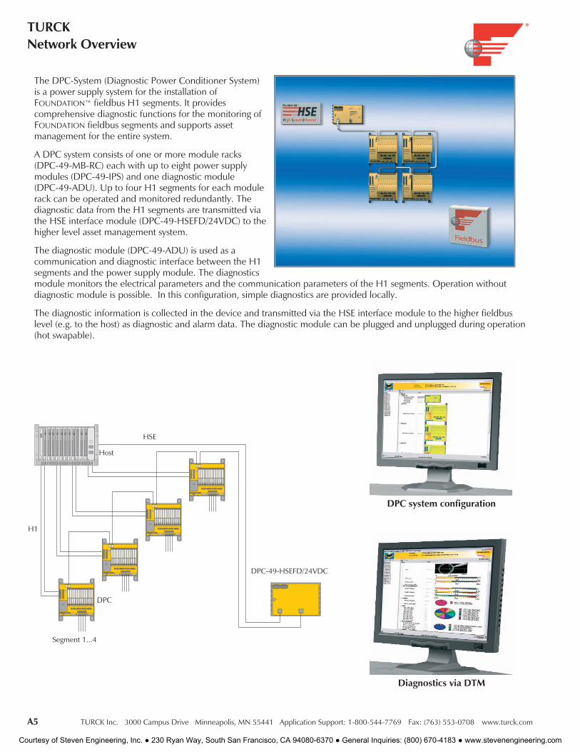
The DPC-System (Diagnostic Power Conditioner System)is a power supply system for the installation ofFOUNDATION™ fieldbus H1 segments. It providescomprehensive diagnostic functions for the monitoring ofFOUNDATION fieldbus segments and supports assetmanagement for the entire system.
A DPC system consists of one or more module racks(DPC-49-MB-RC) each with up to eight power supplymodules (DPC-49-IPS) and one diagnostic module(DPC-49-ADU). Up to four H1 segments for each modulerack can be operated and monitored redundantly. Thediagnostic data from the H1 segments are transmitted viathe HSE interface module (DPC-49-HSEFD/24VDC) to thehigher level asset management system.
The diagnostic module (DPC-49-ADU) is used as acommunication and diagnostic interface between the H1segments and the power supply module. The diagnosticsmodule monitors the electrical parameters and the communication parameters of the H1 segments. Operation withoutdiagnostic module is possible. In this configuration, simple diagnostics are provided locally.
The diagnostic information is collected in the device and transmitted via the HSE interface module to the higher fieldbuslevel (e.g. to the host) as diagnostic and alarm data. The diagnostic module can be plugged and unplugged during operation(hot swapable).
Segment 1...4
DPC
H1
Host
HSE
DPC-49-HSEFD/24VDC
DPC system configuration
Diagnostics via DTM
Courtesy of Steven Engineering, Inc. ● 230 Ryan Way, South San Francisco, CA 94080-6370 ● General Inquiries: (800) 670-4183 ● www.stevenengineering.com
TURCK Inc. 3000 Campus Drive Minneapolis, MN 55441 Application Support: 1-800-544-7769 Fax: (763) 553-0708 www.turck.com A6
IndustrialAutomation
FOU
ND
ATI
ON™
field
bus
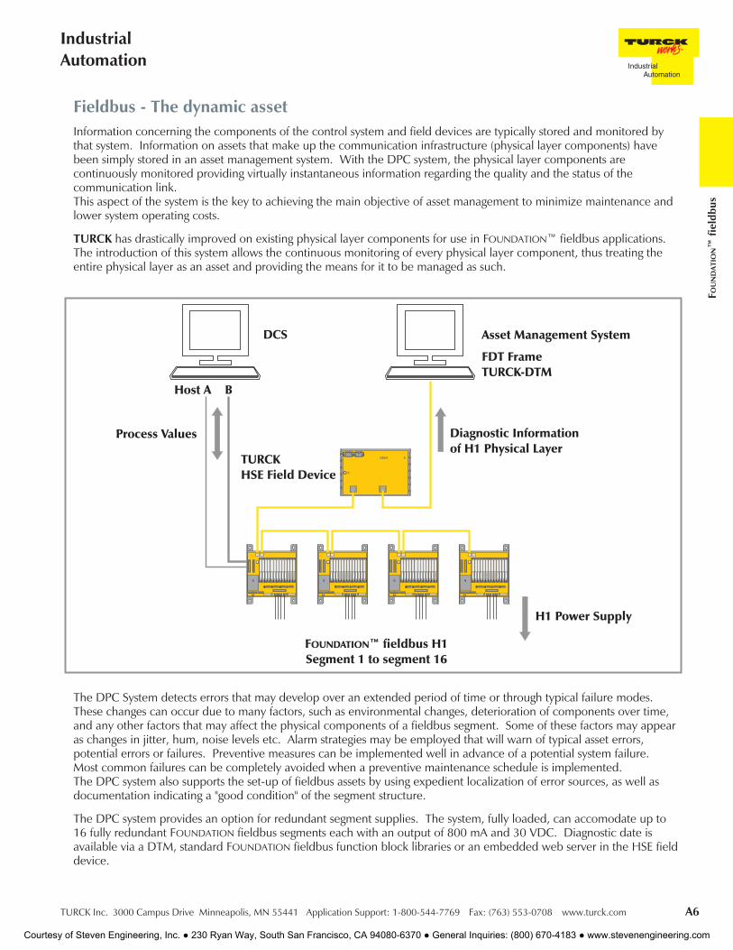
Fieldbus - The dynamic assetInformation concerning the components of the control system and field devices are typically stored and monitored bythat system. Information on assets that make up the communication infrastructure (physical layer components) havebeen simply stored in an asset management system. With the DPC system, the physical layer components arecontinuously monitored providing virtually instantaneous information regarding the quality and the status of thecommunication link.This aspect of the system is the key to achieving the main objective of asset management to minimize maintenance andlower system operating costs.
TURCK has drastically improved on existing physical layer components for use in FOUNDATION™ fieldbus applications.The introduction of this system allows the continuous monitoring of every physical layer component, thus treating theentire physical layer as an asset and providing the means for it to be managed as such.
The DPC System detects errors that may develop over an extended period of time or through typical failure modes.These changes can occur due to many factors, such as environmental changes, deterioration of components over time,and any other factors that may affect the physical components of a fieldbus segment. Some of these factors may appearas changes in jitter, hum, noise levels etc. Alarm strategies may be employed that will warn of typical asset errors,potential errors or failures. Preventive measures can be implemented well in advance of a potential system failure.Most common failures can be completely avoided when a preventive maintenance schedule is implemented.The DPC system also supports the set-up of fieldbus assets by using expedient localization of error sources, as well asdocumentation indicating a "good condition" of the segment structure.
The DPC system provides an option for redundant segment supplies. The system, fully loaded, can accomodate up to16 fully redundant FOUNDATION fieldbus segments each with an output of 800 mA and 30 VDC. Diagnostic date isavailable via a DTM, standard FOUNDATION fieldbus function block libraries or an embedded web server in the HSE fielddevice.
Courtesy of Steven Engineering, Inc. ● 230 Ryan Way, South San Francisco, CA 94080-6370 ● General Inquiries: (800) 670-4183 ● www.stevenengineering.com

A7 TURCK Inc. 3000 Campus Drive Minneapolis, MN 55441 Application Support: 1-800-544-7769 Fax: (763) 553-0708 www.turck.com
TURCKNetwork Overview
Conventional
In a traditional control system I/O devices in the field are individually wired to a central controller, which is responsible forall control function processing in the system. This type of system typically consumes a lot of physical space (due to theamount of wire and the number of I/O cards in the PLC or DCS) and requires a lot of design and labor to install.Additionally, finding errors in this kind of system can be very time consuming because of the number of possible error points(each physical wire termination).
FOUNDATION fieldbus
In the fieldbus system the I/O devices are wired to a trunk line (segment) using tee connectors or multi-drop boxes. Ratherthan separate pairs of wires carrying data to and from each I/O device, the devices use a common pair of wires forcommunication, with each having a turn to “talk” on the network. Instead of performing all the control functions in thehost, the FOUNDATION fieldbus system allows for control blocks to be executed in the field devices themselves, creating anefficient, high integrity system. One device on the network is responsible for scheduling communication between thevarious devices on the system. This is called the Link Active Scheduler (LAS). It can be the host interface or a device in thefield. In most FOUNDATION fieldbus systems at least one backup LAS is defined as well. This allows communication andcontrol to continue in case the original LAS device fails. Most FOUNDATION fieldbus devices are powered completely from thenetwork supply. In some cases a device may draw enough current to make it impractical to power it from the network. Inthese cases the device is typically powered from a separate (auxiliary) supply.
Another key benefit of using FOUNDATION fieldbus is the ease of adding I/O devices to the system in the future. Because it isa serial bus where all devices use the same wires for communication, a device can be added by simply splicing it onto thenetwork. This eliminates the need to pull a new wire pair all the way back to the controller.
FOUNDATION fieldbus devices also typically include a multitude of parameters and diagnostic information, all accessible overthe network. Advanced diagnostics and maintenance scheduling are made much easier with this feature.
Transmitters
Wiring to field
Fieldbus cable
Transmitters
FOUNDATION fieldbusdrop to devices
Courtesy of Steven Engineering, Inc. ● 230 Ryan Way, South San Francisco, CA 94080-6370 ● General Inquiries: (800) 670-4183 ● www.stevenengineering.com

TURCK Inc. 3000 Campus Drive Minneapolis, MN 55441 Application Support: 1-800-544-7769 Fax: (763) 553-0708 www.turck.com A8
IndustrialAutomation
FOU
ND
ATI
ON™
field
bus
Communication Signal
The FOUNDATION™ fieldbus H1 communication signal is a square waveform superimposed on a DC carrier. The frequencyof the signal is 31.25 Khz. Although it is not a requirement, most devices derive their supply power from the fieldbuscommunications cable. The fieldbus specification states that devices must not be polarity sensitive. However, it is goodelectrical practice to have all devices wired with the same polarities. The voltage range allowed for proper operation is 9 to32 VDC. A typical fieldbus device will consume 20 mA of current.
Fieldbus Cable Specifications
The specifications for fieldbus H1 physical media are defined by IEC 61158-2 and the ISA-S50.02 Part 2 Physical LayerStandards. The same standard is also listed in the FOUNDATION fieldbus specifications under 31.25 Kbps Physical Layer ProfileFF-816-1.4. There are essentially four types of cable designations for fieldbus. Type A cable preferred for new installations,because it allows for the most versatile lengths. The other cable types are for installations where cable already exists from4-20 mA systems. See table 1.
Type Cable Description Conductor Size Maximum LengthType A Shielded, Twisted Pair 18 AWG 1900 m (6232 ft.)
Type B Shielded, Multi Twisted Pair 22 AWG 1200 m (3936 ft.)
Type C Unshielded, Multi Twisted Pair 26 AWG 400 m (1312 ft.)
Type D Shielded, Untwisted Pair 16 AWG 200 m (656 ft.)
Idealized FOUNDATION fieldbus communication signal
Typical FOUNDATION fieldbus cable, with ground wire
Table 1
Courtesy of Steven Engineering, Inc. ● 230 Ryan Way, South San Francisco, CA 94080-6370 ● General Inquiries: (800) 670-4183 ● www.stevenengineering.com
A9 TURCK Inc. 3000 Campus Drive Minneapolis, MN 55441 Application Support: 1-800-544-7769 Fax: (763) 553-0708 www.turck.com
TURCKNetwork Overview
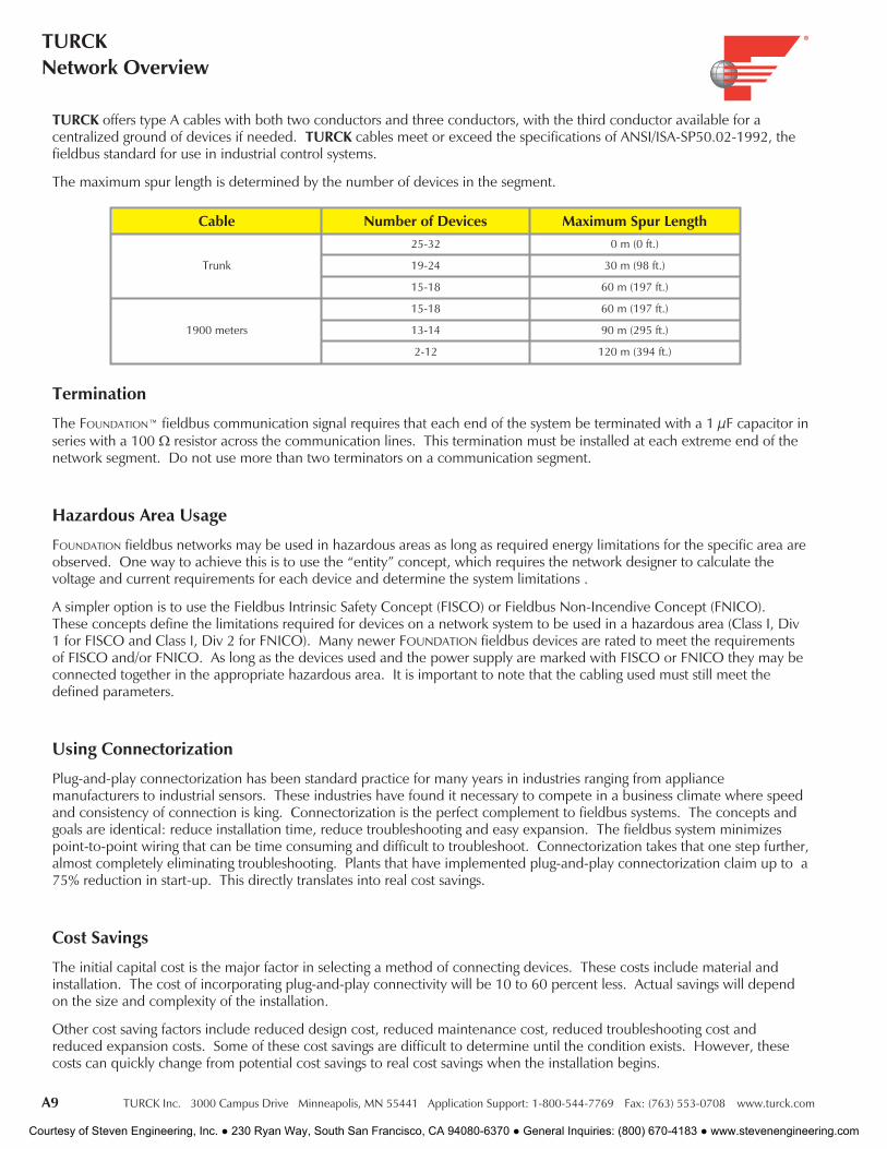
TURCK offers type A cables with both two conductors and three conductors, with the third conductor available for acentralized ground of devices if needed. TURCK cables meet or exceed the specifications of ANSI/ISA-SP50.02-1992, thefieldbus standard for use in industrial control systems.
The maximum spur length is determined by the number of devices in the segment.
Cable Number of Devices Maximum Spur Length
Trunk
25-32 0 m (0 ft.)
19-24 30 m (98 ft.)
15-18 60 m (197 ft.)
1900 meters
15-18 60 m (197 ft.)
13-14 90 m (295 ft.)
2-12 120 m (394 ft.)
Termination
The FOUNDATION™ fieldbus communication signal requires that each end of the system be terminated with a 1 µF capacitor inseries with a 100 Ω resistor across the communication lines. This termination must be installed at each extreme end of thenetwork segment. Do not use more than two terminators on a communication segment.
Hazardous Area Usage
FOUNDATION fieldbus networks may be used in hazardous areas as long as required energy limitations for the specific area areobserved. One way to achieve this is to use the “entity” concept, which requires the network designer to calculate thevoltage and current requirements for each device and determine the system limitations .
A simpler option is to use the Fieldbus Intrinsic Safety Concept (FISCO) or Fieldbus Non-Incendive Concept (FNICO).These concepts define the limitations required for devices on a network system to be used in a hazardous area (Class I, Div1 for FISCO and Class I, Div 2 for FNICO). Many newer FOUNDATION fieldbus devices are rated to meet the requirementsof FISCO and/or FNICO. As long as the devices used and the power supply are marked with FISCO or FNICO they may beconnected together in the appropriate hazardous area. It is important to note that the cabling used must still meet thedefined parameters.
Using Connectorization
Plug-and-play connectorization has been standard practice for many years in industries ranging from appliancemanufacturers to industrial sensors. These industries have found it necessary to compete in a business climate where speedand consistency of connection is king. Connectorization is the perfect complement to fieldbus systems. The concepts andgoals are identical: reduce installation time, reduce troubleshooting and easy expansion. The fieldbus system minimizespoint-to-point wiring that can be time consuming and difficult to troubleshoot. Connectorization takes that one step further,almost completely eliminating troubleshooting. Plants that have implemented plug-and-play connectorization claim up to a75% reduction in start-up. This directly translates into real cost savings.
Cost Savings
The initial capital cost is the major factor in selecting a method of connecting devices. These costs include material andinstallation. The cost of incorporating plug-and-play connectivity will be 10 to 60 percent less. Actual savings will dependon the size and complexity of the installation.
Other cost saving factors include reduced design cost, reduced maintenance cost, reduced troubleshooting cost andreduced expansion costs. Some of these cost savings are difficult to determine until the condition exists. However, thesecosts can quickly change from potential cost savings to real cost savings when the installation begins.
Courtesy of Steven Engineering, Inc. ● 230 Ryan Way, South San Francisco, CA 94080-6370 ● General Inquiries: (800) 670-4183 ● www.stevenengineering.com
TURCK Inc. 3000 Campus Drive Minneapolis, MN 55441 Application Support: 1-800-544-7769 Fax: (763) 553-0708 www.turck.com A10
IndustrialAutomation
FOU
ND
ATI
ON™
field
bus
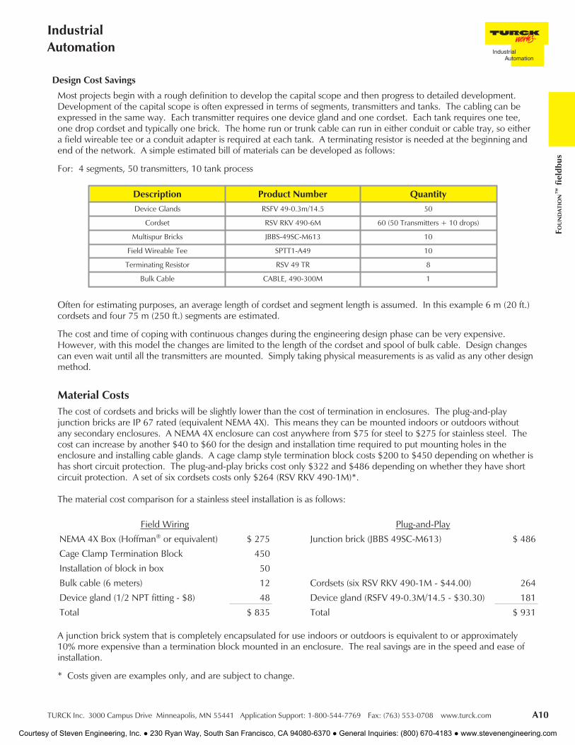
Most projects begin with a rough definition to develop the capital scope and then progress to detailed development.Development of the capital scope is often expressed in terms of segments, transmitters and tanks. The cabling can beexpressed in the same way. Each transmitter requires one device gland and one cordset. Each tank requires one tee,one drop cordset and typically one brick. The home run or trunk cable can run in either conduit or cable tray, so eithera field wireable tee or a conduit adapter is required at each tank. A terminating resistor is needed at the beginning andend of the network. A simple estimated bill of materials can be developed as follows:
For: 4 segments, 50 transmitters, 10 tank process
Description Product Number QuantityDevice Glands RSFV 49-0.3m/14.5 50
Cordset RSV RKV 490-6M 60 (50 Transmitters + 10 drops)
Multispur Bricks JBBS-49SC-M613 10
Field Wireable Tee SPTT1-A49 10
Terminating Resistor RSV 49 TR 8
Bulk Cable CABLE, 490-300M 1
Often for estimating purposes, an average length of cordset and segment length is assumed. In this example 6 m (20 ft.)cordsets and four 75 m (250 ft.) segments are estimated.
The cost and time of coping with continuous changes during the engineering design phase can be very expensive.However, with this model the changes are limited to the length of the cordset and spool of bulk cable. Design changescan even wait until all the transmitters are mounted. Simply taking physical measurements is as valid as any other designmethod.
Design Cost Savings
The cost of cordsets and bricks will be slightly lower than the cost of termination in enclosures. The plug-and-playjunction bricks are IP 67 rated (equivalent NEMA 4X). This means they can be mounted indoors or outdoors withoutany secondary enclosures. A NEMA 4X enclosure can cost anywhere from $75 for steel to $275 for stainless steel. Thecost can increase by another $40 to $60 for the design and installation time required to put mounting holes in theenclosure and installing cable glands. A cage clamp style termination block costs $200 to $450 depending on whether ishas short circuit protection. The plug-and-play bricks cost only $322 and $486 depending on whether they have shortcircuit protection. A set of six cordsets costs only $264 (RSV RKV 490-1M)*.
The material cost comparison for a stainless steel installation is as follows:
Field Wiring Plug-and-Play
NEMA 4X Box (Hoffman® or equivalent) $ 275 Junction brick (JBBS 49SC-M613) $ 486
Cage Clamp Termination Block 450
Installation of block in box 50
Bulk cable (6 meters) 12 Cordsets (six RSV RKV 490-1M - $44.00) 264
Device gland (1/2 NPT fitting - $8) 48 Device gland (RSFV 49-0.3M/14.5 - $30.30) 181
Total $ 835 Total $ 931
A junction brick system that is completely encapsulated for use indoors or outdoors is equivalent to or approximately10% more expensive than a termination block mounted in an enclosure. The real savings are in the speed and ease ofinstallation.
* Costs given are examples only, and are subject to change.
Material Costs
Courtesy of Steven Engineering, Inc. ● 230 Ryan Way, South San Francisco, CA 94080-6370 ● General Inquiries: (800) 670-4183 ● www.stevenengineering.com

A11 TURCK Inc. 3000 Campus Drive Minneapolis, MN 55441 Application Support: 1-800-544-7769 Fax: (763) 553-0708 www.turck.com
TURCKNetwork Overview
Installation Savings
The cost of installing a plug-and-play connector system can be 90% lower than terminating in cage clamps. The timerequired to make a plug-and-play connection is less than 30 seconds per connection. The time required to strip the jacket,prepare the conductors, feed the cable through a gland, insert the wires into the terminals and tighten the cable gland is 5 to10 minutes per connection. This is further complicated when the installation is in a physically demanding location. At alabor cost of $28/hour per NECA labor units, this adds up fast. Terminating this many connections on just a 6-port junctionbrick means a difference of $38.73 as compared to $2.80. Further savings are often hidden since the wiring errors areeliminated.
Field Wiring Plug-and-Play
Install 6 connectors to brick (1/2 min. ea) $ 1.40 Install 6 connectors to brick (1/2 min. ea) $ 1.40
Install 6 cables to device (10 min. ea) 28.00 Install 6 connectors to brick (1/2 min. ea) 1.40
Termination check of system (20 min.) 9.33 Termination check of system (n/a) -----
Total $ 38.73 Total $ 2.80
Maintenance Savings
One of the most important features with plug-and-play connectors is that transmitters can be taken on and off the bus veryquickly - with little or no disruptions to operations and no disruptions to the bus. A device can be added to a junction brickspare port much more easily than any terminal strip. Any conceivable change required in the process can be made simplyby planning a couple of spare ports.
Courtesy of Steven Engineering, Inc. ● 230 Ryan Way, South San Francisco, CA 94080-6370 ● General Inquiries: (800) 670-4183 ● www.stevenengineering.com
TURCK Inc. 3000 Campus Drive Minneapolis, MN 55441 Application Support: 1-800-544-7769 Fax: (763) 553-0708 www.turck.com A12
IndustrialAutomation
FOU
ND
ATI
ON™
field
bus
Notes:
Courtesy of Steven Engineering, Inc. ● 230 Ryan Way, South San Francisco, CA 94080-6370 ● General Inquiries: (800) 670-4183 ● www.stevenengineering.com
B1 TURCK Inc. 3000 Campus Drive Minneapolis, MN 55441 Application Support: 1-800-544-7769 Fax: (763) 553-0708 www.turck.com
TURCKNetwork Overview
Courtesy of Steven Engineering, Inc. ● 230 Ryan Way, South San Francisco, CA 94080-6370 ● General Inquiries: (800) 670-4183 ● www.stevenengineering.com

TURCK Inc. 3000 Campus Drive Minneapolis, MN 55441 Application Support: 1-800-544-7769 Fax: (763) 553-0708 www.turck.com B2
IndustrialAutomation
Dev
iceN
et
DeviceNet™ System DescriptionDeviceNet is a low-cost communications protocol that eliminates hard wiring and connects industrial devices such as limitswitches, photoelectric sensors, valve manifolds, motor starters, process sensors, bar code readers, variable frequency drives,panel displays and operator interfaces to a network. DeviceNet's direct connection provides improved communicationbetween devices, as well as important device-level diagnostics not easily accessible or available through hard-wired I/Ointerfaces.
DeviceNet is based on the Controller Area Network (CAN) broadcast-oriented communication architecture. CAN uses abus arbitration method, CSMA/BA, that assures the highest priority message always gets use of the bus in the event of a datacollision. The DeviceNet protocol further defines message priorities such that I/O messages are given top priority andconfiguration messages have lower priority.
A DeviceNet network supports up to 64 nodes and virtually an unlimited amount of I/O. The bus uses a trunkline/droplinetopology, where bus power and communication are supplied on a single cable. Bus power is 24 VDC and supplies currentto operate the nodes and (typically) power input devices. Some TURCK stations require an additional 24 VDC auxiliarypower to supply current for outputs.
DeviceNet allows peer-to-peer data exchange (where a DeviceNet node can initiate communication with other nodes orpeers), and a master/slave configuration in which the master node initiates all communication and all other nodes, or slaves,respond to the master node’s requests.
Typical System Configuration
C
A
B
C
D
C
C D
E
D
D
E
A typical DeviceNet system consists of the following parts:
• A - Controller
• B - Power Supply
• C - DeviceNet Cable
• D - DeviceNet I/O Modules (or Slaves)
• E - Terminating Resistors
DeviceNet stations require a network master (also called a scanner) to interface the stations to the host controller.TURCK DeviceNet stations are designed to be fully compatible with DeviceNet equipment from other manufacturers.
D
Courtesy of Steven Engineering, Inc. ● 230 Ryan Way, South San Francisco, CA 94080-6370 ● General Inquiries: (800) 670-4183 ● www.stevenengineering.com
B3 TURCK Inc. 3000 Campus Drive Minneapolis, MN 55441 Application Support: 1-800-544-7769 Fax: (763) 553-0708 www.turck.com
TURCKNetwork Overview
Communication Signal and Power
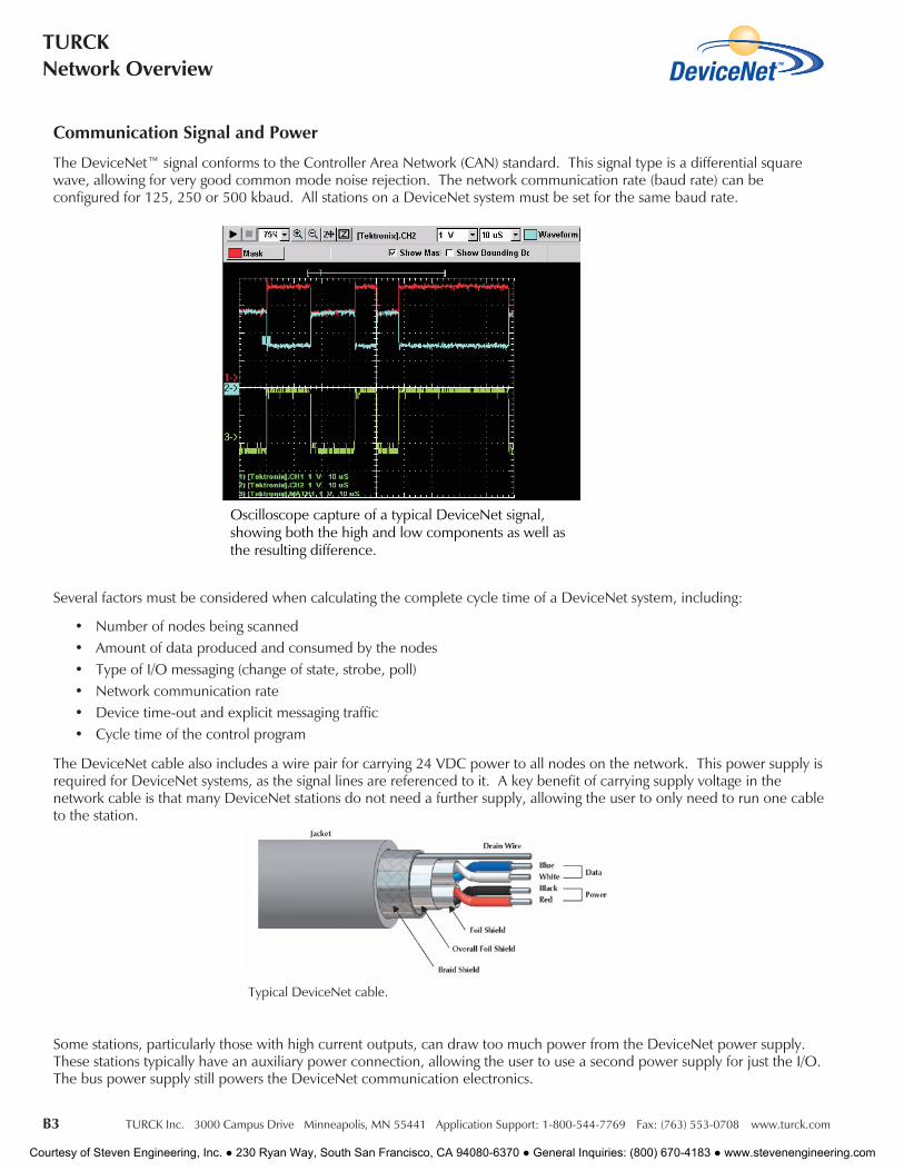
The DeviceNet™ signal conforms to the Controller Area Network (CAN) standard. This signal type is a differential squarewave, allowing for very good common mode noise rejection. The network communication rate (baud rate) can beconfigured for 125, 250 or 500 kbaud. All stations on a DeviceNet system must be set for the same baud rate.
Several factors must be considered when calculating the complete cycle time of a DeviceNet system, including:
• Number of nodes being scanned• Amount of data produced and consumed by the nodes• Type of I/O messaging (change of state, strobe, poll)• Network communication rate• Device time-out and explicit messaging traffic• Cycle time of the control program
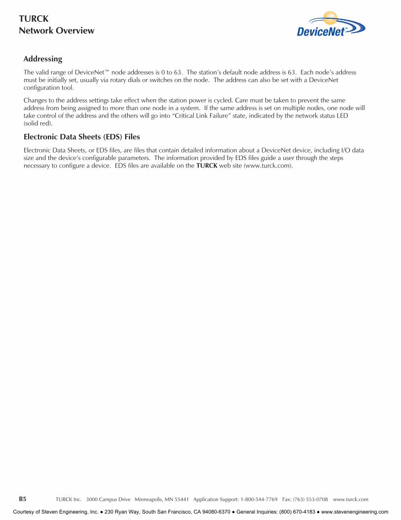
The DeviceNet cable also includes a wire pair for carrying 24 VDC power to all nodes on the network. This power supply isrequired for DeviceNet systems, as the signal lines are referenced to it. A key benefit of carrying supply voltage in thenetwork cable is that many DeviceNet stations do not need a further supply, allowing the user to only need to run one cableto the station.
Some stations, particularly those with high current outputs, can draw too much power from the DeviceNet power supply.These stations typically have an auxiliary power connection, allowing the user to use a second power supply for just the I/O.The bus power supply still powers the DeviceNet communication electronics.
Oscilloscope capture of a typical DeviceNet signal,showing both the high and low components as well asthe resulting difference.
Typical DeviceNet cable.
Courtesy of Steven Engineering, Inc. ● 230 Ryan Way, South San Francisco, CA 94080-6370 ● General Inquiries: (800) 670-4183 ● www.stevenengineering.com

TURCK Inc. 3000 Campus Drive Minneapolis, MN 55441 Application Support: 1-800-544-7769 Fax: (763) 553-0708 www.turck.com B4
IndustrialAutomation
Dev
iceN
et
Cordsets
TURCK offers a complete line of molded DeviceNet™ cordsets to facilitate network installation, resulting in a faster start-upand fewer wiring errors. The bus and drop cables are specially designed foil-shielded, high-flex cables with very lowinductance and capacitance to minimize propagation delay time. DeviceNet cables consist of a shielded and twisted datapair, as well as a shielded and twisted power pair for the 24 VDC bus power, with an additional outer shield.
In most cases, bus cable connections are made using 5-pin minifast ® (7/8-16 UN) or eurofast ® (M12) connectors. Avariety of stations are also available that support terminal-block type connections.
TURCK cordsets for the DeviceNet system are available in standard lengths. Contact your local sales representative to ordercustom lengths.
Maximum Ratings
The DeviceNet bus uses trunk and drop topology. The trunk is the main communication cable, and requires a 121 ohmresistor at both ends. The maximum length of the trunk depends on the communication rate and the cable type. Drops arebranches off the trunk, and may be from zero to 6 m (20 ft) in length. The cumulative drop lengths are dependent on thecommunication rate. The following table shows the maximum ratings for a trunk using thick, mid and thin cable. Thick andthin DeviceNet communication cable types are defined by the DeviceNet specification; mid cable is a hybrid of the two thatis offered by TURCK.
Diagnostics
TURCK stations provide increased diagnostics when used with standard proximity or photoelectric sensors and discreteactuators. TURCK stations also serve as a buffer between I/O devices and the DeviceNet bus by detecting short-circuitswithout disrupting DeviceNet communication.
For deluxe style stations, each I/O point on the station provides state and status data. State data represents the real worldvalue of the I/O device; for example, when the sensor is on or the actuator is off. Status data indicates short-circuits in theI/O device or in the wiring between the device and the station. Some models also use status data to indicate open circuits.
State and status data are transferred to the DeviceNet scanner where it is available for fault handling in the control program.Additionally, each input and output has a multicolored LED to indicate its state and status and pinpoint I/O problemsquickly; for example the module status LED indicates the internal health of the station, and the network status LED indicatesthe station’s communication on the DeviceNet network.
CommunicationRate
Thick TrunkLength
(maximum)
Mid TrunkLength
(maximum)
Thin TrunkLength
(maximum)
Drop Length(maximum per
drop)
Drop Length(cumulative)
Nodes(maximum)
125 kbps250 kbps500 kbps
500 m (1640 ft.)250 m (820 ft.)100 m (328 ft.)
300 m (984 ft.)250 m (820 ft.)100 m (328 ft.)
100 m (328 ft.)100 m (328 ft.)100 m (328 ft.)
6 m (20 ft.)6 m (20 ft.)6 m (20 ft.)
156 m (512 ft.)78 m (256 ft.)39 m (128 ft.)
646464
minifast connector eurofast connector
Courtesy of Steven Engineering, Inc. ● 230 Ryan Way, South San Francisco, CA 94080-6370 ● General Inquiries: (800) 670-4183 ● www.stevenengineering.com
B5 TURCK Inc. 3000 Campus Drive Minneapolis, MN 55441 Application Support: 1-800-544-7769 Fax: (763) 553-0708 www.turck.com
TURCKNetwork Overview
Addressing
The valid range of DeviceNet™ node addresses is 0 to 63. The station’s default node address is 63. Each node’s addressmust be initially set, usually via rotary dials or switches on the node. The address can also be set with a DeviceNetconfiguration tool.
Changes to the address settings take effect when the station power is cycled. Care must be taken to prevent the sameaddress from being assigned to more than one node in a system. If the same address is set on multiple nodes, one node willtake control of the address and the others will go into “Critical Link Failure” state, indicated by the network status LED(solid red).
Electronic Data Sheets (EDS) Files
Electronic Data Sheets, or EDS files, are files that contain detailed information about a DeviceNet device, including I/O datasize and the device’s configurable parameters. The information provided by EDS files guide a user through the stepsnecessary to configure a device. EDS files are available on the TURCK web site (www.turck.com).
Courtesy of Steven Engineering, Inc. ● 230 Ryan Way, South San Francisco, CA 94080-6370 ● General Inquiries: (800) 670-4183 ● www.stevenengineering.com
TURCK Inc. 3000 Campus Drive Minneapolis, MN 55441 Application Support: 1-800-544-7769 Fax: (763) 553-0708 www.turck.com B6
IndustrialAutomation
Dev
iceN
et
Notes:
Courtesy of Steven Engineering, Inc. ● 230 Ryan Way, South San Francisco, CA 94080-6370 ● General Inquiries: (800) 670-4183 ● www.stevenengineering.com

C1 TURCK Inc. 3000 Campus Drive Minneapolis, MN 55441 Application Support: 1-800-544-7769 Fax: (763) 553-0708 www.turck.com
TURCKNetwork Overview
Courtesy of Steven Engineering, Inc. ● 230 Ryan Way, South San Francisco, CA 94080-6370 ● General Inquiries: (800) 670-4183 ● www.stevenengineering.com
TURCK Inc. 3000 Campus Drive Minneapolis, MN 55441 Application Support: 1-800-544-7769 Fax: (763) 553-0708 www.turck.com C2
IndustrialAutomation
AS-i
nter
face
AS-interface® System DescriptionAS-interface (commonly referred to as AS-i) is a low-level I/O interface system. It was originally intended to be a simple, lowcost system that would be easy to install and maintain. With that philosophy in mind, the original developers designed AS-ias a discrete-only two-wire system. It incorporated features like automatic station addressing, and power and data werecarried on a single untwisted pair of wires.
As the demand for AS-i grew, so did the demand for more complex devices. The next major version of AS-i, v2.1, extendedthe protocol to include seamless transfer of analog data, transmission of simple diagnostic data and an extended addressingscheme that effectively doubled the number of stations allowed on the network. The newest version of AS-i, v3.0, has goneeven further, allowing more options for analog data and much more detailed diagnostic information to be communicated.New versions of AS-i are backward compatible and support slaves from earlier versions. Additionally, AS-i was one of thefirst network systems to incorporate a safety protocol, allowing emergency-stop and machine-stop systems to be seamlesslyintegrated with the network.
AS-i can be used as a stand alone network or can be connected to a higher level system, such as DeviceNet™ orPROFIBUS ®-DP, through a gateway. The gateway acts as a slave to the higher system and a master to the AS-i system.
Typical System Configuration
Basic Parts List
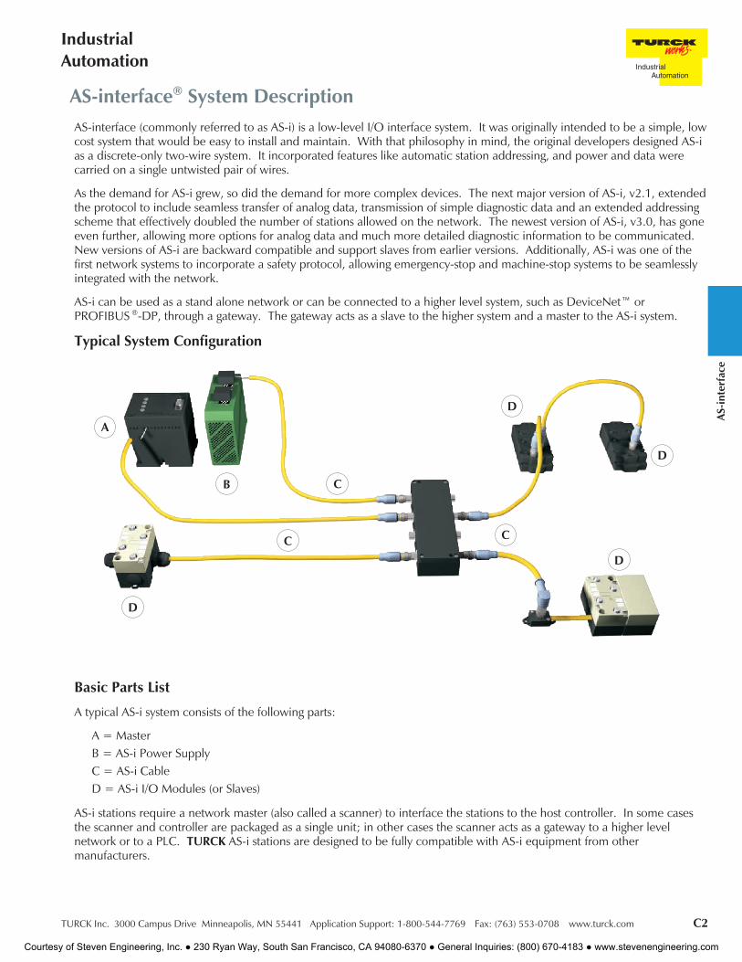
A typical AS-i system consists of the following parts:
A = MasterB = AS-i Power SupplyC = AS-i CableD = AS-i I/O Modules (or Slaves)
AS-i stations require a network master (also called a scanner) to interface the stations to the host controller. In some casesthe scanner and controller are packaged as a single unit; in other cases the scanner acts as a gateway to a higher levelnetwork or to a PLC. TURCK AS-i stations are designed to be fully compatible with AS-i equipment from othermanufacturers.
D
A
B
C
D
D
D
C
C
Courtesy of Steven Engineering, Inc. ● 230 Ryan Way, South San Francisco, CA 94080-6370 ● General Inquiries: (800) 670-4183 ● www.stevenengineering.com

C3 TURCK Inc. 3000 Campus Drive Minneapolis, MN 55441 Application Support: 1-800-544-7769 Fax: (763) 553-0708 www.turck.com
TURCKNetwork Overview
Communication Signal and Power
AS-i communication uses a Manchester encoded data signal, which results in a very noise immune system, even on thespecified untwisted and unshielded cable. The communication media is a simple two-wire cable. Both power (30 VDC) forthe stations and data are carried on the same wires. This means the DC supply must be "decoupled" from the network (thepower supply cannot "see" the AC data component on the wire). Special AS-i power supplies are available, whichincorporate this feature in a single package. Optionally, a separate AS-i decoupling component (power conditioner) can bepurchased, allowing the user to use a standard 30 VDC supply.
In many cases the AS-i communication power supply is not sufficient to power higher current outputs on the network. Inthese cases most manufacturers make AS-i slaves which draw I/O current from a separate auxiliary supply. The stationelectronics are still powered from the AS-i network.
Communication Rate/Cycle Time
AS-i communicates at a fixed data rate of 167 kbps. The system’s cycle time is very predictable because of the simplecommunication scheme and fixed data rate. For example, a network with 31 slaves will have a cycle time of less than 5 ms.A network with 62 slaves (all A and B addresses used) will have a cycle time of less than 10 ms. If analog slaves are beingused, the cycle time will change to account for the fact that an analog word takes multiple network cycles to transmit.
Maximum Ratings
The AS-i system uses a freeform layout topology. Up to 100 m of cable can be used on a segment before a repeater ortuner needs to be installed to allow the network to be extended beyond the 100 m limit. No terminating resistors arerequired.
Diagnostics
AS-i has limited field diagnostic capability, due to the limited amount of data transferred in each message. With v2.1, aperipheral fault bit can be reported by an AS-i station to indicate a fault with a field device. This allows the user to easilydetermine the location of a system fault down to the station level. AS-i v3.0 has even more diagnostic capabilities, allowingasynchronous “mailbox” messaging to receive more detailed error information.
Bihl+Wiedemann AS-i masters (provided by TURCK) provide comprehensive information about the status of each stationon the network by using register based tables to display each occupied network address.
Addressing
The original AS-i system allowed only 4 bits of data to be transferred in each message for a fast and efficient data transfersystem. Slaves could be addressed from one to 31, but with the growth of the network more than 31 stations were oftenrequired. Beginning with AS-i v2.1 stations were available with “AB” addressing. This scheme allows the station to beaddressed from 1A to 31A or 1B to 31B, with 62 total slaves with four discrete inputs and three discrete outputs each. Theextended address range (and the limitation to three outputs) is achieved by using one output bit as an AB address.
When both A and B addressed slaves are on the same network, they are scanned on alternating cycles (first all the A slavesare scanned, then all the B slaves). Both AB and single-address slaves can be on the same network. In this case thesingle-address (non AB style) slaves are scanned every cycle. It’s important to note that not all v2.1 slaves use this addressingscheme, although it is often referred to as v2.1 addressing.
Analog Data
Although the original AS-i version only allowed discrete data transfer, v2.1 and higher support seamless analog data transfer.This is accomplished by sending a portion of the analog data on each of several consecutive network cycles; for example, a16-bit word of data requires seven network cycles. Further, AS-i v3.0 allows analog data to be transferred in a single cycleby consuming more than one address for the analog slave.
Courtesy of Steven Engineering, Inc. ● 230 Ryan Way, South San Francisco, CA 94080-6370 ● General Inquiries: (800) 670-4183 ● www.stevenengineering.com

TURCK Inc. 3000 Campus Drive Minneapolis, MN 55441 Application Support: 1-800-544-7769 Fax: (763) 553-0708 www.turck.com C4
IndustrialAutomation
AS-i
nter
face
AS-interface Masters and GatewaysAS-i networks can be controlled by stand-alone "masters" or by "gateways" to higher-level networks. The terms “master” and“gateway” as used here differ in the following way: A master is an AS-i controller that provides a direct link to the host (PLC,PC, DCS etc.); a gateway is an AS-i master, while also being a slave to a higher-level system (such as DeviceNet™,PROFIBUS ®-DP or Ethernet). In the case of a gateway, the AS-i information is compiled by the AS-i master andcommunicated through the higher-level system as a standard slave data map. Gateways are often used to incorporate theflexibility of an AS-i system into an already planned or existing system using a different, higher-level system.
TURCK & Bihl+Wiedemann
Bihl+Wiedemann, considered the "AS-i masters”, is the leading supplier of AS-i master and gateway products. Their broadproduct range enables users to select from a wide variety of higher level fieldbuses or PC/PLC control solutions.Additionally, Bihl+Wiedemann provides a wide variety of analog AS-i slaves, PC-board level devices for OEMs andsophisticated AS-i accessory products. TURCK has partnered with Bihl+Wiedemann to distribute and support theirproducts in North America.
Cordsets
TURCK offers a complete line of molded AS-i cordsets to facilitate network installation, resulting in a faster start-up andfewer wiring errors. The cables are specially designed, high-flex cables with very low inductance and capacitance tominimize propagation delay time. AS-i cables consist of a single untwisted and unshielded wire pair that carries both 30VDC power and the network data. AS-i was originally designed for use with flat cable using an insulation displacementconnection technology, but the use of round cables with sealed connectors has become more common. TURCK providesboth cable options.
Typical AS-i cable
Courtesy of Steven Engineering, Inc. ● 230 Ryan Way, South San Francisco, CA 94080-6370 ● General Inquiries: (800) 670-4183 ● www.stevenengineering.com

D1 TURCK Inc. 3000 Campus Drive Minneapolis, MN 55441 Application Support: 1-800-544-7769 Fax: (763) 553-0708 www.turck.com
TURCKNetwork Overview
Courtesy of Steven Engineering, Inc. ● 230 Ryan Way, South San Francisco, CA 94080-6370 ● General Inquiries: (800) 670-4183 ● www.stevenengineering.com
TURCK Inc. 3000 Campus Drive Minneapolis, MN 55441 Application Support: 1-800-544-7769 Fax: (763) 553-0708 www.turck.com D2
IndustrialAutomation
PRO
FIBU
S
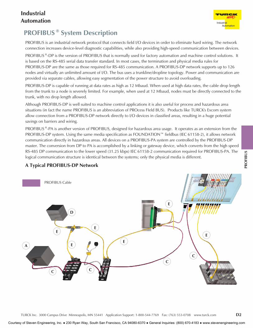
PROFIBUS ® System DescriptionPROFIBUS is an industrial network protocol that connects field I/O devices in order to eliminate hard wiring. The networkconnection increases device-level diagnostic capabilities, while also providing high-speed communication between devices.
PROFIBUS ®-DP is the version of PROFIBUS that is normally used for factory automation and machine control solutions. Itis based on the RS-485 serial data transfer standard. In most cases, the termination and physical media rules forPROFIBUS-DP are the same as those required for RS-485 communication. A PROFIBUS-DP network supports up to 126nodes and virtually an unlimited amount of I/O. The bus uses a trunkline/dropline topology. Power and communication areprovided via separate cables, allowing easy segmentation of the power structure to avoid overloading.
PROFIBUS-DP is capable of running at data rates as high as 12 Mbaud. When used at high data rates, the cable drop lengthfrom the trunk to a node is severely limited. For example, when used at 12 Mbaud, nodes must be directly connected to thetrunk, with no drop length allowed.
Although PROFIBUS-DP is well suited to machine control applications it is also useful for process and hazardous areasituations (in fact the name PROFIBUS is an abbreviation of PROcess FIeld BUS). Products like TURCK's Excom systemallow connection from a PROFIBUS-DP network directly to I/O devices in classified areas, resulting in a huge potentialsavings on barriers and wiring.
PROFIBUS ®-PA is another version of PROFIBUS, designed for hazardous area usage. It operates as an extension from thePROFIBUS-DP system. Using the same media specification as FOUNDATION™ fieldbus (IEC 61158-2), it allows networkcommunication directly in hazardous areas. All devices on a PROFIBUS-PA system are controlled by the PROFIBUS-DPmaster. The conversion from DP to PA is accomplished by a linking or gateway device, which converts from the high speedRS-485 DP communication to the lower speed (31.25 kbps) IEC 61158-2 communication required for PROFIBUS-PA. Thelogical communication structure is identical between the systems; only the physical media is different.
A Typical PROFIBUS-DP Network
PROFIBUS Cable
C
E
C
C
A
D
E
EE
E
E
C
Courtesy of Steven Engineering, Inc. ● 230 Ryan Way, South San Francisco, CA 94080-6370 ● General Inquiries: (800) 670-4183 ● www.stevenengineering.com

D3 TURCK Inc. 3000 Campus Drive Minneapolis, MN 55441 Application Support: 1-800-544-7769 Fax: (763) 553-0708 www.turck.com
TURCKNetwork Overview
Basic Parts ListA typical PROFIBUS ® system consists of the following parts:
• A - Master
• B - Slaves
• C - Communication cable
• D - Power supply
• E - Power cable (PROFIBUS-DP)
PROFIBUS stations require a network master (also called a scanner) to interface the stations to the host controller. TURCKPROFIBUS-DP stations are designed to be fully compatible with PROFIBUS-DP equipment from other manufacturers.
Communication Rate/Cycle TimePROFIBUS-DP specifications define multiple transmission speeds ranging from 9.6 kbaud to 12 Mbaud. All nodes on anetwork must communicate at the same rate.
The complete cycle time of a PROFIBUS-DP system is affected by several factors:
• Number of nodes being scanned
• Amount of data produced and consumed by the nodes
• Network communication rate
• Cycle time of the control program
All of these factors must be considered when calculating the cycle time of a particular network.
A Typical PROFIBUS ®-PA Network, Connected to a Higher-Level PROFIBUS ®-DP System
PROFIBUS-DP RS-485 Transmissions
FLDP-IOM 88-0001
Segmentcoupler/link
PROFIBUS-PA IEC61158-2 transmissions
Process Control System
Transmitters
Transmitters
RSV RKV 48-1M
RSV 48TR
JBBS-48SC-M633
RKV 40-1M
RSFK BC
Trunk LineRSV RKV 48-1M
RSV RKV 48-1M
Courtesy of Steven Engineering, Inc. ● 230 Ryan Way, South San Francisco, CA 94080-6370 ● General Inquiries: (800) 670-4183 ● www.stevenengineering.com
TURCK Inc. 3000 Campus Drive Minneapolis, MN 55441 Application Support: 1-800-544-7769 Fax: (763) 553-0708 www.turck.com D4
IndustrialAutomation
PRO
FIBU
S
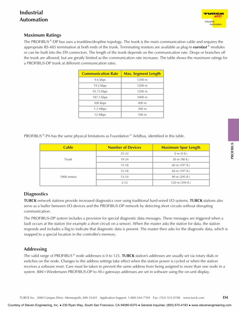
Maximum RatingsThe PROFIBUS ®-DP bus uses a trunkline/dropline topology. The trunk is the main communication cable and requires theappropriate RS-485 termination at both ends of the trunk. Terminating resistors are available as plug-in eurofast ® modulesor can be built into the D9 connectors. The length of the trunk depends on the communication rate. Drops or branches offthe trunk are allowed, but are greatly limited as the communication rate increases. The table shows the maximum ratings fora PROFIBUS-DP trunk at different communication rates.
PROFIBUS ®-PA has the same physical limitations as Foundation™ fieldbus, identified in this table.
Cable Number of Devices Maximum Spur Length
Trunk
25-32 0 m (0 ft.)
19-24 30 m (98 ft.)
15-18 60 m (197 ft.)
1900 meters
15-18 60 m (197 ft.)
13-14 90 m (295 ft.)
2-12 120 m (394 ft.)
DiagnosticsTURCK network stations provide increased diagnostics over using traditional hard-wired I/O systems. TURCK stations alsoserve as a buffer between I/O devices and the PROFIBUS-DP network by detecting short circuits without disruptingcommunication.
The PROFIBUS-DP system includes a provision for special diagnostic data messages. These messages are triggered when afault occurs at the station (for example a short circuit on a sensor). When the master asks the station for data, the stationresponds and includes a flag to indicate that diagnostic data is present. The master then asks for the diagnostic data, which ismapped to a special location in the controller's memory.
AddressingThe valid range of PROFIBUS ® node addresses is 0 to 125. TURCK station's addresses are usually set via rotary dials orswitches on the node. Changes to the address settings take effect when the station power is cycled or when the stationreceives a software reset. Care must be taken to prevent the same address from being assigned to more than one node in asystem. Bihl+Wiedemann PROFIBUS-DP to AS-i gateways addresses are set in software using the on-unit display.
Communication Rate Max. Segment Length9.6 kbps 1200 m
19.2 kbps 1200 m
93.75 kbps 1200 m
187.5 kbps 1000 m
500 kbps 400 m
1.5 Mbps 200 m
12 Mbps 100 m
Courtesy of Steven Engineering, Inc. ● 230 Ryan Way, South San Francisco, CA 94080-6370 ● General Inquiries: (800) 670-4183 ● www.stevenengineering.com

D5 TURCK Inc. 3000 Campus Drive Minneapolis, MN 55441 Application Support: 1-800-544-7769 Fax: (763) 553-0708 www.turck.com
TURCKNetwork Overview
CordsetsTURCK offers a complete line of molded PROFIBUS ®-DP and PROFIBUS ®-PA cordsets to facilitate network installation,resulting in a faster start-up and fewer wiring errors. The bus and drop cables are specially designed foil-shielded, high-flexcables with very low inductance and capacitance to minimize propagation delay time. PROFIBUS-DP cables consist of ashielded and twisted data pair with a bare drain wire. PROFIBUS-PA cables feature a shielded, twisted pair for data and buspower and a drain wire.
In most cases, connections of the bus cable to the stations are made using 5-pin reverse-key eurofast ® (M12) connectors forPROFIBUS-DP. A variety of stations are also available that support D9 type connections. Power for most stations is providedthrough one or two 5-pin minifast ® (7/8-16UN) connectors.
PROFIBUS-PA connections are typically made with minifast style connectors, though eurofast connections are available aswell.
TURCK cordsets for the PROFIBUS ® system are available in standard lengths. Please contact your local sales representativeto order custom lengths.
Typical PROFIBUS-DP Cable
Typical PROFIBUS-PA Cable
GSD FilesGSD files contain detailed information about a PROFIBUS-DP device, including I/O data size and the devices configurableparameters. The information in an GSD file, when used with a PROFIBUS-DP configuration tool, guides a user through thesteps necessary to configure a device. GSD files are available on the TURCK website (www.turck.com).
Drain WireBrownBlue
Drain WireBlueBrownGreen/Yellow
Jacket
Data
Jacket
Aluminum ArmorFoil Shield
Data
Foil ShieldInner Jacket
Braid Shield
Red
Green
Braided Shield
Drain Wire
Jacket
Foil Shield
RedGreen
Drain Wire
JacketInner Jacket
Foil Shield
Aluminum Armor
Courtesy of Steven Engineering, Inc. ● 230 Ryan Way, South San Francisco, CA 94080-6370 ● General Inquiries: (800) 670-4183 ● www.stevenengineering.com
TURCK Inc. 3000 Campus Drive Minneapolis, MN 55441 Application Support: 1-800-544-7769 Fax: (763) 553-0708 www.turck.com D6
IndustrialAutomation
PRO
FIBU
S
Notes:
Courtesy of Steven Engineering, Inc. ● 230 Ryan Way, South San Francisco, CA 94080-6370 ● General Inquiries: (800) 670-4183 ● www.stevenengineering.com

E1 TURCK Inc. 3000 Campus Drive Minneapolis, MN 55441 Application Support: 1-800-544-7769 Fax: (763) 553-0708 www.turck.com
TURCKNetwork Overview Ethernet
Courtesy of Steven Engineering, Inc. ● 230 Ryan Way, South San Francisco, CA 94080-6370 ● General Inquiries: (800) 670-4183 ● www.stevenengineering.com

TURCK Inc. 3000 Campus Drive Minneapolis, MN 55441 Application Support: 1-800-544-7769 Fax: (763) 553-0708 www.turck.com E2
IndustrialAutomation
Ethe
rnet
System DescriptionEthernet is the most popular protocol used to connect office computers and peripherals today. It is increasingly finding itsway into other applications, and is rapidly becoming the network of choice for higher level industrial control applications.Ethernet is primarily used to connect PLCs, computers, HMI displays and other high level components.
The term “Ethernet” actually refers to the lower level communication structure. Various different versions, orimplementations, of Ethernet are available, such as Ethernet/IP™, Profinet and Modbus-TCP. It is important to note thatwhile all of these different specifications use the same physical communication method and can operate on the same cablesimultaneously, they cannot necessarily communicate with each other. For example, Modbus-TCP devices cannotcommunicate with Ethernet/IP devices. This is because the messages and communication protocol have been defineddifferently for these systems, even though the physical electrical structure is the same. Think of it as two people who speakdifferent languages; they speak by moving air with their mouths, but the rules of the languages are different.
TURCK’s BL67 Ethernet gateways provide a convenient way to connect industrial I/O devices directly to the Ethernetsystem, expediting monitoring and troubleshooting for the overall control scheme.
Typical System Configuration
Basic Parts List
A typical Ethernet system consists of the following parts:
• A - Controller
• B - Switches
• C - Ethernet I/O modules
• D - Ethernet cable
• E - Power supply
Ethernet I/O modules act as servers on a network. A client device is needed to retrieve data from and post data to theserver. This is analogous to an office network, where the client PC on a user’s desk may actively connect with multipleservers to access information in different areas of the enterprise. TURCK Ethernet stations are designed to be fullycompatible with established Ethernet standards for industrial use.
(Not shown)
B
C
A
E
C
D
Courtesy of Steven Engineering, Inc. ● 230 Ryan Way, South San Francisco, CA 94080-6370 ● General Inquiries: (800) 670-4183 ● www.stevenengineering.com
E3 TURCK Inc. 3000 Campus Drive Minneapolis, MN 55441 Application Support: 1-800-544-7769 Fax: (763) 553-0708 www.turck.com
TURCKNetwork Overview Ethernet
AddressingIndustrial Ethernet stations use the IP addressing scheme. An address defined by this scheme consists of four byte valuesusually displayed in decimal form, for example, 192.168.1.254. Different classifications of networks require differentportions of this address to be constant for all devices on the network (referred to as a “subnet”). This means that thenumber of stations allowed on a particular network varies depending on what class of subnet is being used. If the first threebytes of the IP address are constant (which is common), then the remaining byte may be addressed between 2 and 254,resulting in 253 possible addresses.
Maximum RatingsEthernet allows different maximum cable lengths depending on the type of cable being used. Normally an Ethernetsegment may be as long as 100 m, where 90 m must be solid core cable and the remaining 10 m can be stranded patchcords.
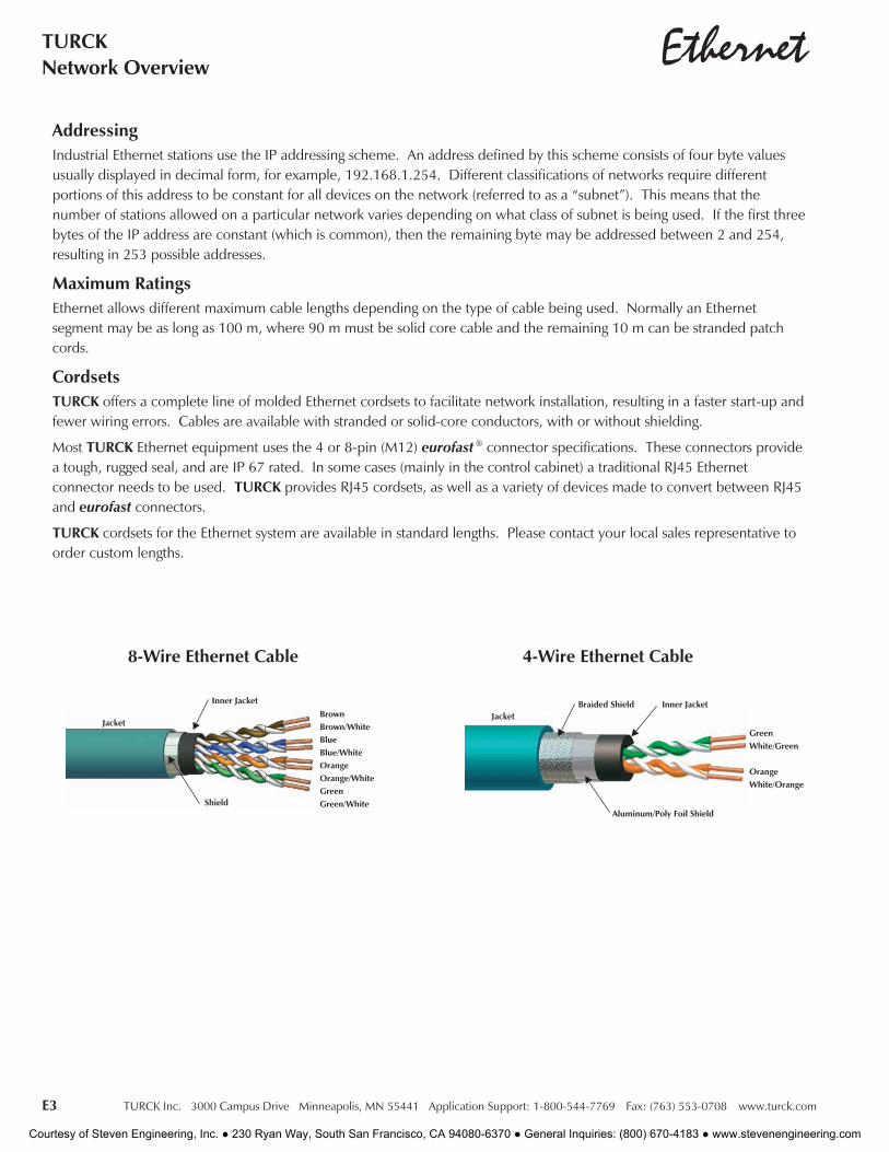
CordsetsTURCK offers a complete line of molded Ethernet cordsets to facilitate network installation, resulting in a faster start-up andfewer wiring errors. Cables are available with stranded or solid-core conductors, with or without shielding.
Most TURCK Ethernet equipment uses the 4 or 8-pin (M12) eurofast ® connector specifications. These connectors providea tough, rugged seal, and are IP 67 rated. In some cases (mainly in the control cabinet) a traditional RJ45 Ethernetconnector needs to be used. TURCK provides RJ45 cordsets, as well as a variety of devices made to convert between RJ45and eurofast connectors.
TURCK cordsets for the Ethernet system are available in standard lengths. Please contact your local sales representative toorder custom lengths.
BrownBrown/WhiteBlueBlue/WhiteOrangeOrange/WhiteGreenGreen/White
Inner Jacket
Jacket
Shield
GreenWhite/Green
OrangeWhite/Orange
Aluminum/Poly Foil Shield
Inner JacketJacket
Braided Shield
8-Wire Ethernet Cable 4-Wire Ethernet Cable
Courtesy of Steven Engineering, Inc. ● 230 Ryan Way, South San Francisco, CA 94080-6370 ● General Inquiries: (800) 670-4183 ● www.stevenengineering.com
TURCK Inc. 3000 Campus Drive Minneapolis, MN 55441 Application Support: 1-800-544-7769 Fax: (763) 553-0708 www.turck.com E4
IndustrialAutomation
Ethe
rnet
Notes:
Courtesy of Steven Engineering, Inc. ● 230 Ryan Way, South San Francisco, CA 94080-6370 ● General Inquiries: (800) 670-4183 ● www.stevenengineering.com

F1 TURCK Inc. 3000 Campus Drive Minneapolis, MN 55441 Application Support: 1-800-544-7769 Fax: (763) 553-0708 www.turck.com
TURCKProcess Wiring Solutions
Type ITC cable, or Instrumentation Tray Cable, provides acost effective alternative for installation of low powerinstrumentation and control circuits. The NationalElectrical Code's (NEC) Article 727 permits the use of ITC-rated cables “in industrial establishments where theconditions of maintenance and supervision ensure thatonly qualified persons service the installation”. It may beused in “instrumentation and control circuits operating at
150 volts or less and 5 amps or less.” Permitted uses include installation in cable trays or basket trays (Figure 1), or asExposed Run wiring in specified circumstances.
Figure 1
Code Requirements for Flexible Process Wiring ProductsOrdinary (Nonhazardous) Locations
One of the permitted uses as of ITC cable is illustrated in Figure 2. NEC's, Article 727.4(5) allows ITC cable withoutmetallic sheath or armor between cable tray and equipment in lengths not to exceed 15 m (50 ft.), where the cable issupported and protected against physical damage using mechanical protection, such as struts, angles, or channels.
Figure 2
≤50 ft.
Mechanically protected
Another permitted use of ITC cable that increases flexibility isillustrated in Figure 3. NEC Article 727.4 (4) allows ITC cableto be used “as open wiring where enclosed in a smoothmetallic sheath, continuous corrugated metallic sheath, orinterlocking tape armor applied over the nonmetallic sheathin accordance with 727.6. The cable shall be supported andsecured at intervals not exceeding 1.8 m (6 ft.).”
When using armored cable, there is no requirement forfurther mechanical protection or a length limitation. Whenusing ITC cable that complies with the requirements of NEC727.4(6) no further protection is required.
Figure 3
Supported every 6 ft.
Courtesy of Steven Engineering, Inc. ● 230 Ryan Way, South San Francisco, CA 94080-6370 ● General Inquiries: (800) 670-4183 ● www.stevenengineering.com

TURCK Inc. 3000 Campus Drive Minneapolis, MN 55441 Application Support: 1-800-544-7769 Fax: (763) 553-0708 www.turck.com F2
ProcessAutomation
Proc
ess
Wir
ing
Envi
ronm
ents
Code Requirements for Flexible Process Wiring ProductsOrdinary (Nonhazardous) Locations
Requirements NEC 727.4(6) allows the installation of ITC cable that complies with the crush and impact of Type MCcable between the cable tray and equipment in lengths not to exceed 15 m (50 ft.) without additional protection. Cablemeeting this requirement is identified as "Exposed Run" or "ER" (Figure 1).
This concept enables convenient wiring methods, given that drops from a cable tray may be made without additionalauxiliary trays or raceways. Additionally, ITC cable uses 300 volt insulation, resulting in smaller diameter, more flexiblecable, with no requirement forspecial (e.g. Class II) power supplies.When the ITC cable concept iscombined with the TURCK processwiring system, the result is anextremely flexible and cost-effectivesystem for process wiring.The basic building blocks of thesystem are device receptacles,junction boxes, and molded cordsets.
≤50 ft.
Exposed Run
Figure 2
Any length
≤50 ft.
≤50 ft.
Any length
Armored cable
Exposed RunExposed Run
Figure 1
Courtesy of Steven Engineering, Inc. ● 230 Ryan Way, South San Francisco, CA 94080-6370 ● General Inquiries: (800) 670-4183 ● www.stevenengineering.com
F3 TURCK Inc. 3000 Campus Drive Minneapolis, MN 55441 Application Support: 1-800-544-7769 Fax: (763) 553-0708 www.turck.com
TURCKProcess Wiring Solutions
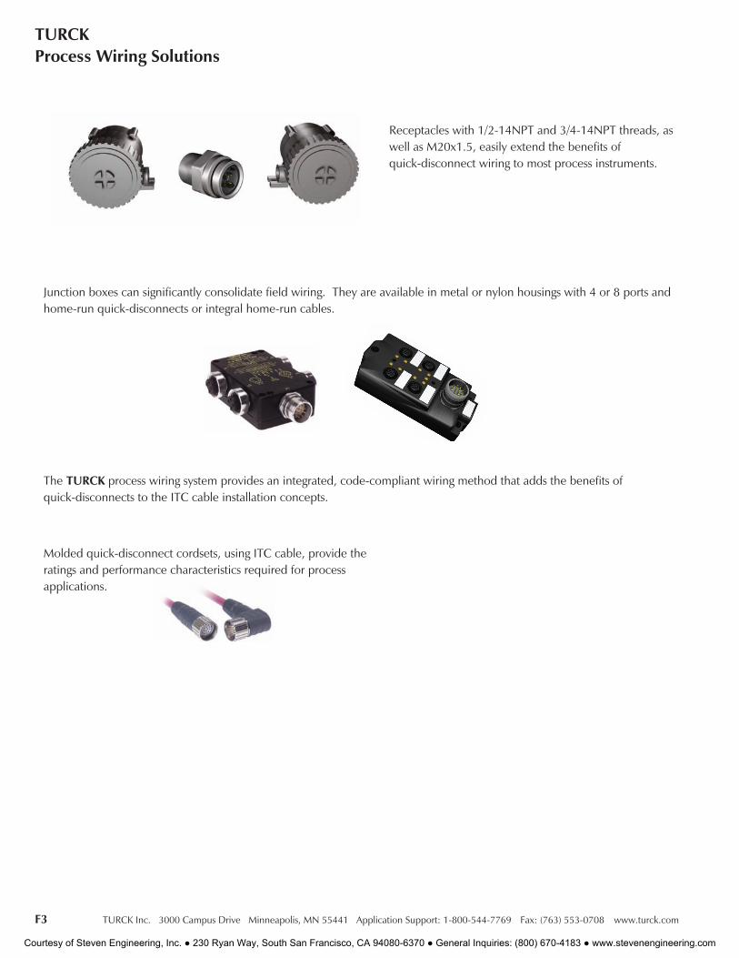
Junction boxes can significantly consolidate field wiring. They are available in metal or nylon housings with 4 or 8 ports andhome-run quick-disconnects or integral home-run cables.
The TURCK process wiring system provides an integrated, code-compliant wiring method that adds the benefits ofquick-disconnects to the ITC cable installation concepts.
Molded quick-disconnect cordsets, using ITC cable, provide theratings and performance characteristics required for processapplications.
Receptacles with 1/2-14NPT and 3/4-14NPT threads, aswell as M20x1.5, easily extend the benefits ofquick-disconnect wiring to most process instruments.
Courtesy of Steven Engineering, Inc. ● 230 Ryan Way, South San Francisco, CA 94080-6370 ● General Inquiries: (800) 670-4183 ● www.stevenengineering.com
TURCK Inc. 3000 Campus Drive Minneapolis, MN 55441 Application Support: 1-800-544-7769 Fax: (763) 553-0708 www.turck.com F4
ProcessAutomation
Proc
ess
Wir
ing
Envi
ronm
ents
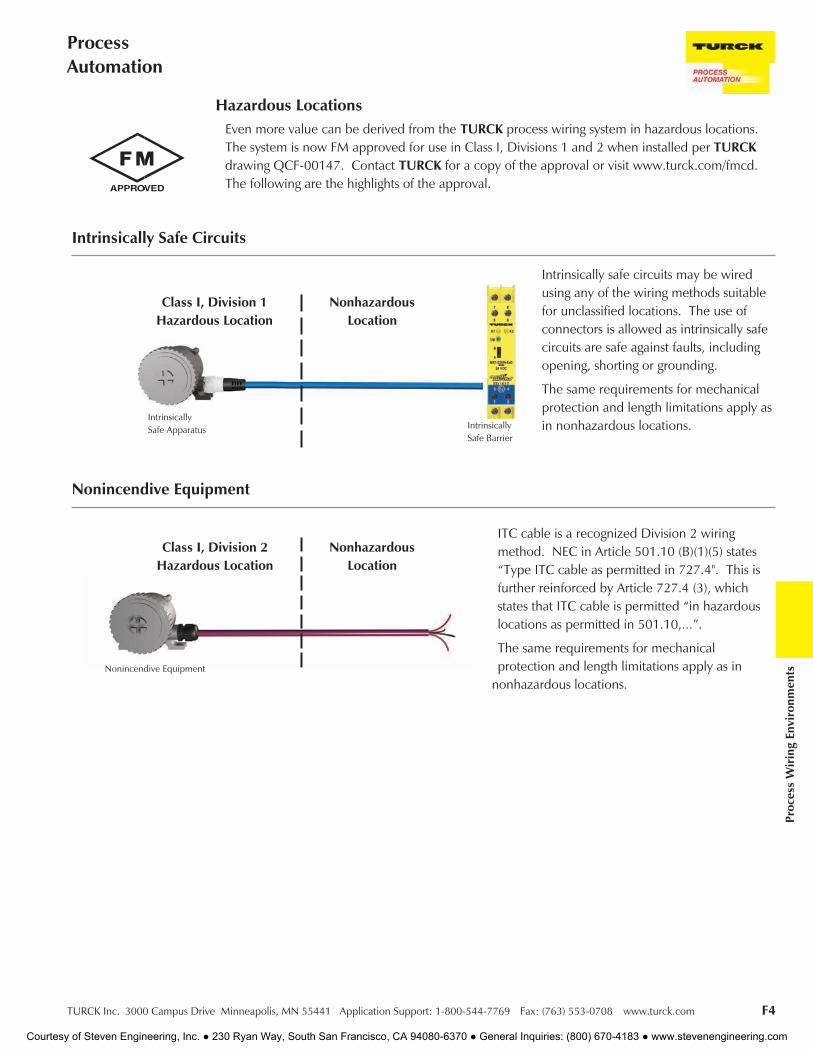
Even more value can be derived from the TURCK process wiring system in hazardous locations.The system is now FM approved for use in Class I, Divisions 1 and 2 when installed per TURCKdrawing QCF-00147. Contact TURCK for a copy of the approval or visit www.turck.com/fmcd.The following are the highlights of the approval.
Hazardous Locations
ITC cable is a recognized Division 2 wiringmethod. NEC in Article 501.10 (B)(1)(5) states“Type ITC cable as permitted in 727.4". This isfurther reinforced by Article 727.4 (3), whichstates that ITC cable is permitted “in hazardouslocations as permitted in 501.10,...”.
The same requirements for mechanicalprotection and length limitations apply as in
nonhazardous locations.
IntrinsicallySafe Barrier
IntrinsicallySafe Apparatus
Class I, Division 1Hazardous Location
NonhazardousLocation
Intrinsically safe circuits may be wiredusing any of the wiring methods suitablefor unclassified locations. The use ofconnectors is allowed as intrinsically safecircuits are safe against faults, includingopening, shorting or grounding.
The same requirements for mechanicalprotection and length limitations apply asin nonhazardous locations.
Intrinsically Safe Circuits
Nonincendive Equipment
NonhazardousLocation
Class I, Division 2Hazardous Location
Nonincendive Equipment
Courtesy of Steven Engineering, Inc. ● 230 Ryan Way, South San Francisco, CA 94080-6370 ● General Inquiries: (800) 670-4183 ● www.stevenengineering.com
F5 TURCK Inc. 3000 Campus Drive Minneapolis, MN 55441 Application Support: 1-800-544-7769 Fax: (763) 553-0708 www.turck.com
TURCKProcess Wiring Solutions
Figure 1
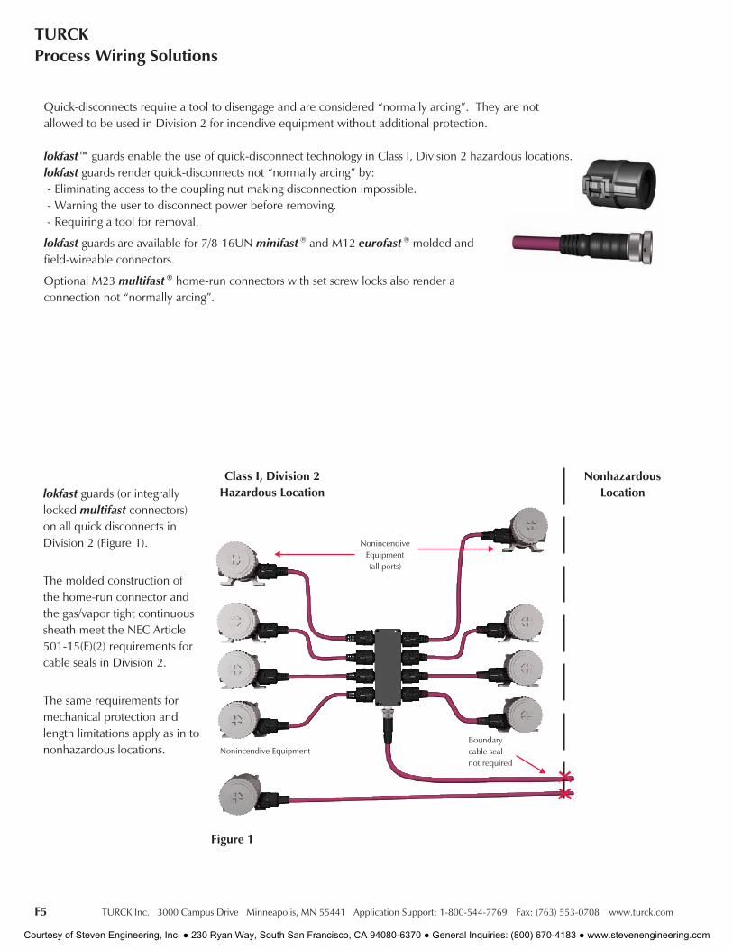
lokfast guards (or integrallylocked multifast connectors)on all quick disconnects inDivision 2 (Figure 1).
The molded construction ofthe home-run connector andthe gas/vapor tight continuoussheath meet the NEC Article501-15(E)(2) requirements forcable seals in Division 2.
The same requirements formechanical protection andlength limitations apply as in tononhazardous locations.
NonhazardousLocation
Class I, Division 2Hazardous Location
Boundarycable sealnot required
Nonincendive Equipment
NonincendiveEquipment(all ports)
Quick-disconnects require a tool to disengage and are considered “normally arcing”. They are notallowed to be used in Division 2 for incendive equipment without additional protection.
lokfast™ guards enable the use of quick-disconnect technology in Class I, Division 2 hazardous locations.lokfast guards render quick-disconnects not “normally arcing” by:- Eliminating access to the coupling nut making disconnection impossible.- Warning the user to disconnect power before removing.- Requiring a tool for removal.
lokfast guards are available for 7/8-16UN minifast ® and M12 eurofast ® molded andfield-wireable connectors.
Optional M23 multifast ® home-run connectors with set screw locks also render aconnection not “normally arcing”.
Courtesy of Steven Engineering, Inc. ● 230 Ryan Way, South San Francisco, CA 94080-6370 ● General Inquiries: (800) 670-4183 ● www.stevenengineering.com
TURCK Inc. 3000 Campus Drive Minneapolis, MN 55441 Application Support: 1-800-544-7769 Fax: (763) 553-0708 www.turck.com F6
ProcessAutomation
Proc
ess
Wir
ing
Envi
ronm
ents
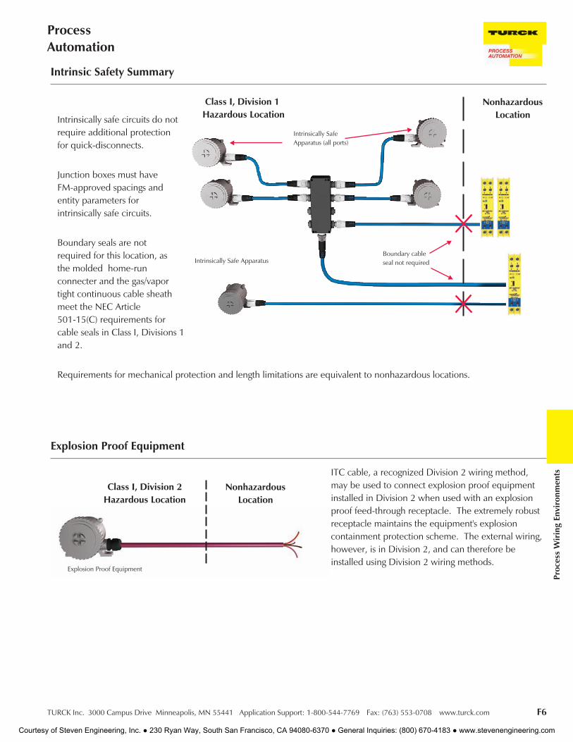
Intrinsic Safety Summary
Intrinsically safe circuits do notrequire additional protectionfor quick-disconnects.
Junction boxes must haveFM-approved spacings andentity parameters forintrinsically safe circuits.
Boundary seals are notrequired for this location, asthe molded home-runconnecter and the gas/vaportight continuous cable sheathmeet the NEC Article501-15(C) requirements forcable seals in Class I, Divisions 1and 2.
Requirements for mechanical protection and length limitations are equivalent to nonhazardous locations.
NonhazardousLocation
Class I, Division 1Hazardous Location
Boundary cableseal not requiredIntrinsically Safe Apparatus
Intrinsically SafeApparatus (all ports)
Explosion Proof Equipment
Class I, Division 2Hazardous Location
NonhazardousLocation
Explosion Proof Equipment
ITC cable, a recognized Division 2 wiring method,may be used to connect explosion proof equipmentinstalled in Division 2 when used with an explosionproof feed-through receptacle. The extremely robustreceptacle maintains the equipment's explosioncontainment protection scheme. The external wiring,however, is in Division 2, and can therefore beinstalled using Division 2 wiring methods.
Courtesy of Steven Engineering, Inc. ● 230 Ryan Way, South San Francisco, CA 94080-6370 ● General Inquiries: (800) 670-4183 ● www.stevenengineering.com

F7 TURCK Inc. 3000 Campus Drive Minneapolis, MN 55441 Application Support: 1-800-544-7769 Fax: (763) 553-0708 www.turck.com
TURCKProcess Wiring Solutions
The NEC is a set of guidelines for installation of electrical devices, including cables, meant to reduce the risk of electricalshock, fire, etc. The NEC is simply a code and local laws may or may not require installation based on the NEC. Checklocal laws for applicability.
The NEC generally does not cover cables installed inside a machine. Any cables installed in an exposed manner, on theoutside of a machine or from one machine to something else, must be an approved type and installed in accordance withthe appropriate NEC articles.
UL (Underwriters Laboratory) and CSA (Canadian Standards Association) are the primary sources in North America forapproving cables to specific standards. While a cable installed within a piece of machinery does not fall under the NEC,most people want to install an approved cable. TURCK cables have both UL and CSA approvals. Many of these approvalsare the UL AWM (Appliance Wiring) approvals and are acceptable for use in a UL approved device. A UL Listed cable maybe installed outside a machine per the NEC standards. UL Listed cables available from TURCK include NEC designations forhard duty cables (SOOW, SJOOW, STOOW, SEOW), armored cables (MC), and tray-rated cables (PLTC, ITC).
Hard duty cables designations are:
S - Service Grade (600V)
SJ - Service Grade Junior (300V)
ST - Service Grade Thermoplastic (600V)
SE - Service Grade Thermoplastic Elastomer (600V)
O - Oil resistant jacket material
OO - Oil resistant jacket and conductor insulation
W - Weather proof
TURCK armored cables are available in 3 different configurations. Type MC cables, type MC cables with ITC/PLTCapprovals and simply ITC/PLTC approved. Armored cables with ITC/PLTC approvals may be installed in an exposed runwithout being offered additional mechanical protection.
Tray-rated cables from TURCK include Instrument Tray Cable (ITC) and/or Power Limited Tray Cable (PLTC).
TURCK NEC type approved cables are dual listed with other UL type approvals. For example, the RKM 126-*M cordset hasa 12 conductor 16 AWG cable with UL AWM 600V approval and ITC/PLTC approval.
Please refer to the NEC and local laws for specific installation requirements based on your environment.
Installing Cable Products in Accordance with the National Electrical Code (NEC)
Courtesy of Steven Engineering, Inc. ● 230 Ryan Way, South San Francisco, CA 94080-6370 ● General Inquiries: (800) 670-4183 ● www.stevenengineering.com
TURCK Inc. 3000 Campus Drive Minneapolis, MN 55441 Application Support: 1-800-544-7769 Fax: (763) 553-0708 www.turck.com F8
ProcessAutomation
Proc
ess
Wir
ing
Envi
ronm
ents
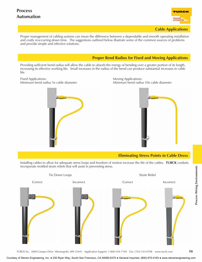
Installing cables to allow for adequate stress loops and freedom of motion increase the life of the cables. TURCK cordsetsincorporate molded strain reliefs that will assist in preventing stress.
Eliminating Stress Points in Cable Dress
Cable Applications
Proper Bend Radius for Fixed and Moving Applications
Proper management of cabling systems can mean the difference between a dependable and smooth operating installationand costly reoccurring down time. The suggestions outlined below illustrate some of the common sources of problemsand provide simple and effective solutions.
Providing sufficient bend radius will allow the cable to absorb the energy of bending over a greater portion of its length,increasing its effective working life. Small increases in the radius of the bend can produce substantial increases in cablelife.
Moving Applications:Minimum bend radius 10x cable diameter
Incorrect
Fixed Applications:Minimum bend radius 5x cable diameter
Strain Relief
CorrectIncorrect
Tie Down Loops
Correct
Courtesy of Steven Engineering, Inc. ● 230 Ryan Way, South San Francisco, CA 94080-6370 ● General Inquiries: (800) 670-4183 ● www.stevenengineering.com

F9 TURCK Inc. 3000 Campus Drive Minneapolis, MN 55441 Application Support: 1-800-544-7769 Fax: (763) 553-0708 www.turck.com
TURCKProcess Wiring Solutions
Cabling for Motion Applications
Cable Bundling Techniques
Where cabling is subjected to linear, angular or rotational motion between two points, always allow adequate cable lengthto absorb the energy imparted by the motion. Use of coiled cords, mechanical support mechanisms, or large, wellsupported cable loops will maximize cable life.
When bundling several cables together, always keep the bundle loose enough to move within itself. Tightly tied bundlescreate both compression and tension stresses when the bundle is moved.
"C" Track
Cable Loop
Incorrect
Coil Cord
Correct
Courtesy of Steven Engineering, Inc. ● 230 Ryan Way, South San Francisco, CA 94080-6370 ● General Inquiries: (800) 670-4183 ● www.stevenengineering.com
TURCK Inc. 3000 Campus Drive Minneapolis, MN 55441 Application Support: 1-800-544-7769 Fax: (763) 553-0708 www.turck.com F10
ProcessAutomation
Proc
ess
Wir
ing
Envi
ronm
ents
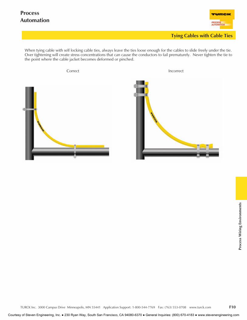
Tying Cables with Cable Ties
When tying cable with self locking cable ties, always leave the ties loose enough for the cables to slide freely under the tie.Over tightening will create stress concentrations that can cause the conductors to fail prematurely. Never tighten the tie tothe point where the cable jacket becomes deformed or pinched.
IncorrectCorrect
Courtesy of Steven Engineering, Inc. ● 230 Ryan Way, South San Francisco, CA 94080-6370 ● General Inquiries: (800) 670-4183 ● www.stevenengineering.com
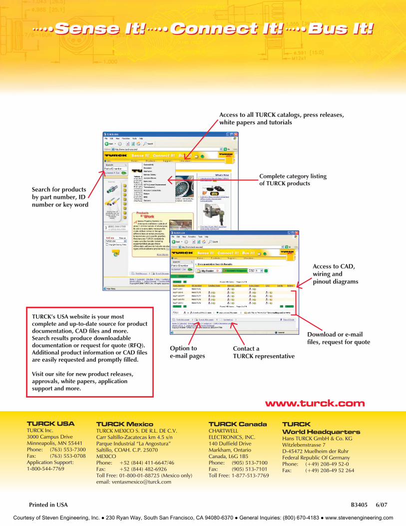
Access to all TURCK catalogs, press releases, white papers and tutorials
Complete category listing of TURCK products
Search for productsby part number, ID number or key word
www.turck.com
TURCK’s USA website is your most complete and up-to-date source for product documentation, CAD fi les and more. Search results produce downloadable documentation or request for quote (RFQ). Additional product information or CAD fi les are easily requested and promptly fi lled.
Visit our site for new product releases, approvals, white papers, application support and more.
Printed in USA B3405 6/07
Option to e-mail pages
Contact a TURCK representative
Download or e-mail fi les, request for quote
Access to CAD, wiring and pinout diagrams
TURCK USATURCK Inc.3000 Campus DriveMinneapolis, MN 55441Phone: (763) 553-7300Fax: (763) 553-0708Application Support:1-800-544-7769
TURCK MexicoTURCK MEXICO S. DE R.L. DE C.V.Carr Saltillo-Zacatecas km 4.5 s/nParque Industrial “La Angostura”Saltillo, COAH. C.P. 25070MEXICOPhone: +52 (844) 411-6647/46Fax: +52 (844) 482-6926 Toll Free: 01-800-01-88725 (Mexico only)email: [email protected]
TURCK CanadaCHARTWELLELECTRONICS, INC.140 Duffi eld DriveMarkham, OntarioCanada, L6G 1B5Phone: (905) 513-7100Fax: (905) 513-7101Toll Free: 1-877-513-7769
TURCKWorld HeadquartersHans TURCK GmbH & Co. KGWitzlebenstrasse 7D-45472 Muelheim der RuhrFederal Republic Of GermanyPhone: (+49) 208-49 52-0Fax: (+49) 208-49 52 264
Courtesy of Steven Engineering, Inc. ● 230 Ryan Way, South San Francisco, CA 94080-6370 ● General Inquiries: (800) 670-4183 ● www.stevenengineering.com