overhearing packet transmissions to reduce preamble ...vinay/papers/06734900.pdf · overhearing...
TRANSCRIPT

Overhearing packet transmissions to reduce preamble overhead and improve throughput in IEEE
802.11 networks
Shantanu Shrivastava+, Vinay J. Ribeirot +Department of Electrical Engineering, and tDepartment of Computer Science and Engineering,
Indian Institute of Technology Delhi, Hauz Khas, New Delhi, India 110016 Email: [email protected]. [email protected]
Abstract-While there has been a significant increase in the data rate carrying capacity of the physical medium of Wi-Fi in recent years, there has not been a proportionate increase in the application layer throughput. The primary cause for this are overheads such as those of the preamble, acknowledgement, and channel access present in the packet data communication.
This paper is a proof of concept for a novel method to increase the data throughput by cutting down preamble overheads. The preamble is present in the beginning of the packet for the purposes of packet detection, automatic gain control, channel estimation and phase error correction. In S02.11, a receiver estimates the channel response afresh for every received packet using its preamble and forgets this channel estimate thereafter. This necessitates the need for a large preamble to be sent with every packet. In our method, a node remembers channel estimates from preambles of packets transmitted (to itself or to any other node) in the recent past (within a coherence time), which it reuses for future received packets. This allows transmitters to reduce the size of the preambles of some packets significantly, thereby improving throughput. We validate our method through detailed physical layer simulations of S02.11n in matlab and show that we can shorten the preamble by as much as 16j.ts for 2x2 MIMO which would bring down the preamble overhead by as much as 50%.
I. INTRODUCTION
Though the present day 802.11 physical layer can transmit data at the rate of up to 1Gbps yet there has not been a proportional increase in application layer throughput in WLAN communications. One of the key reasons for this is the preamble overhead in the packet transmission which is about 200% of the data transmission time for a 1500 byte packet in 802.11 n having data rate of 600 Mbps [1]. A 1500 byte packet in IEEE 802.11n 4x4 MIMO at 600 Mbps takes on average 60fJs of which only 20fJs are used for data transmission while 40fJs is for transmission of preamble (Figure 1).
A WLAN frame also known as PLCP packet data unit(PPDU) starts with a preamble, followed by a header and ends in data symbols. The preamble consists of predefined sequences which help in detecting packets, time synchronization and channel estimation. It is known that the preamble causes significant overhead in the WLAN transmission. The goal of this paper is to reduce this preamble overhead.
In a regular 802.11 transmission, the preamble consist of basically two important fields, the short training field (STF) and the long training field (LTF). While the STF is used for
978-1-4799-3635-9/14/$31.00 ©2014 IEEE
packet detection and phase error correction, the LTF is used for channel estimation at the receiver. The number of STFs and LTFs in a preamble varies depending upon different 802.11 versions and their operating modes. For example, 802.11a has one STF followed by an LTF, while 802.11n has a varying number of LTFs depending upon the number of spatial streams being used to transmit the packet. One way to reduce the preamble size is to drop either the STFs or the LTFs.
500% Average Channe l Access
Overhead
Slots
O l F 5
200% P H Y
layer Data
Pream ble
0 1 2 3 4 5 6 7
221.s�s
Fig. 1. Overheads in 802.l1n transmission
, ,
300%ACK : I Overhead :
I � : Data : :
Since the LTFs are used for channel estimation, if the receiver can use prior knowledge of the channel response then potentially one or more LTFs can be dropped from the preamble and the overhead can be reduced. However, not all prior knowledge of the channel impulse response may be relevant to predicting the current channel response, since wireless channels are in general time-varying primarily due to the small scale fading due to multipath reflections in a closed environment, and relative movement between the transmitter and the receiver. The 802.11 protocol, in fact, does not rely on any prior channel knowledge at all and instead estimates channel parameters afresh for every packet using its preamble.
We posit that prior knowledge obtained from packets overheard within a coherence time of the current packet can indeed be used to obtain a good estimate of current channel conditions, thereby allowing certain preamble fields to be dropped. The coherence time is roughly the duration up to which the channel response is highly correlated or the channel conditions remain same. Consider a case wherein the fading is occurring at walking speed of 1.2km\hr (0.33m\sec). While the coherence time for such a channel undergoing rayleigh fading is about 0.0729 seconds [2], the time for transmitting an extraordinarily large sized packet of size 2.5 KB at 600 Mbps including various overheads, is around 0.001 second

proving that many packets can be transmitted within the same coherence time. This indicates that the many packets can face essentially the same channel response.
In this work, we present a proof of concept of a method to shorten the preambles in 802.11 by overhearing and reusing channel impulse responses from the recent past. To illustrate our method with an example, suppose an AP is transmitting several packets one after another to a particular receiver Rl. The AP first sends a normal 802.11 packet to Rl. The subsequent packets transmitted within a coherence time of this packet are sent with smaller preambles and the channel response estimated from the first packet are used in detecting the data bits (in channel equalization etc.) of these packets. Since after a coherence time, the channel response may be quite different, the entire procedure is restarted, namely a packet with a full preamble is retransmitted.
Note that our method is not limited to this case of an AP transmitting several packets back-to-back to a single receiver. Consider the case where an AP sends a normal 802.11 packet to a receiver Rl (say packet PI) and subsequently sends packet P2 to another receiver R2 within a coherence time of PI. Although PI is not intended for R2, it can use the preamble of PI to estimate the channel response between the AP and itself (R2). Thus R2 can use this estimate of channel response to detect the data bits of P2. Consequently, the AP transmits P2 with a reduced preamble, eliminating certain LTF fields in it. The above examples are only for illustrative purposes and are by no means exhaustive. Our method is not restricted to the case where the AP is the transmitter and is also not restricted to DATA packets. It can be applied to the case where any node is the transmitter and also can be used for ACK packets.
Challenges We enumerate several challenges which must be addressed to implement the ideas described above.
1) Which fields in the preamble to drop: Recent 802.l1 standards (such as 802.11n) use several LTFs in their preambles. Which of these can be dropped to reduce preamble size without significantly hurting BER is a question which must be answered.
2) Determining when to use short preambles: Channel response estimates become stale with time. Hence an optimal time must be found within which short preambles may be used.
3) Informing receiver about type of preamble: The receiver must know if an incoming packet contains a normal or short preamble. Although an 802.11 preamble contains a SIG field to indicate the type of packet (and preamble) being received, this SIG field is placed after the first LTF. This makes eliminating the first LTF a challenge. We suggest a solution which signals the type of preamble by modifying the STF of an 802.11 packet. This enables the receiver to know that even the first LTF may be missing from the packet.
In this paper we present a proof-of-concept of our method and address all of the above challenges. We study our solution using a detailed physical layer model of 802.11n in matlab [3]. A full solution, encompassing both PHY and MAC layers, is beyond the scope of this paper, and is part of future work. We
PLCP Preamble PHY-Header
Fig. 2. General frame format of IEEE802.1l
STF LTF SIG
..... f---.. ... .. f---.. ... .. 1---•• 81l5ec 8Jlsec 4Jlsec
Fig. 3. General preamble format of IEEE802.11a
Data
perform simulation experiments under a time varying channel to determine the optimum time for which either no or one LTF can be transmitted in the preamble for different modulation schemes. Section II of the paper serves as a background for this work by explaining the complete functionality of the preamble. The proposed solution is explained in Section III, design details in Section IV and the simulation results presented in Section V. We describe related work in Section VI and conclude in Section VII.
II. BACKGROUND MATERIAL
In this section we describe the 802.11 preamble and its function in detail.
A. Preamble The different versions of 802.11 protocol have different
frame structures based upon the data rate and backward compatibility. The basic PLCP Protocol Data Unit (PPDU) of IEEE 802.11 has the structure shown in Figure 2.
The role of preamble is crucial as first it helps in enabling a packet transmission to be detected by the receiver either by cross correlation or by auto correlation and second it also helps in channel estimation which is necessary for channel equalization performed before detecting data bits. The preamble essentially has two very important fields the long training fields(LTF) and the short training field (STF). The structure and arrangement of these fields varies depending on the version of IEEE 802.11 but the purpose of these remain same throughout. STF is more concerned with packet detection while LTF is required for channel estimation. We will now have a look at these in detail. The IEEE 802.11a has one Short Training field (STF) and two Long Training field (LTF) constituting a preamble of size 20f.Ls (Figure 3) while an IEEE802.11n greenfield mode (high throughput mode) having two spatial streams has a preamble of size 32f.Ls (Figure 4) [4].
Let us now have a look at each of these fields separately: Short Training Field (STF): STFs are used for automatic gain control and packet detection. Each STF is composed of 10 short training symbols (STS) symbols of each 0.8f.Ls making a total of 8f.Ls. Each STS in turn is a repetition of 16 identical

I l-STF I HT-LTFl I HT-SIG HT-lTF2 I HT-lTF3 Data
- - - - - .�------+� BlAsec BJ.lser 8J.lsec 4J.lsec 41lsec
Fig. 4. General frame format of IEEES02.11n in Greenfield mode
STS STS
.. AGCsignal Detection
STS
0.8 x 10 ",sec
STS I STS I STS STS STS STS
Fine and coarse tim e synchronization
Fig. 5. Structure of STF - similar in both S02.lla and S02.11n
STS I
samples generated by OFDM modulation of an already known PN sequence (Figure 5).
Long Training Field(LTF): LTFs are used for Channel estimation and frequency offset estimation. For 802.1 In [5] two different structure of LTF are there as shown in Figure 6 and Figure 7. Each LTF has one or two long training symbol (LTS) which are OFDM symbols of 64 samples generated from an already known PN sequence. As can be seen in Figures 6 and 7, HT-LTFI has two LTSs each of 3.2/-ls and a guard interval of 1.6/-ls while HT-LTF2 and HT-LTF3 have only one LTS of 3.2/-ls and a guard interval of 0.8/-ls.
Guard Interval (GI) : In IEEE 802.11 GI contains a circular prefix which has 32 samples of an LTS for HT-LTFI and 16 samples of an LTS for HT-LTF2 and HT-LTF3. It prevents inter symbol interference between LTF and STF.
HT-SIG: The high throughput (HT) signal field is used to carry information required to interpret the HT packet formats. It contains information such as the modulation technique being used etc.
B. Preamble Functionality The preamble is used to perform packet detection, fre
quency synchronisation, and channel estimation. Packet Detection: Packet detection is the first task performed at the beginning of a packet reception. Its job is to identify the beginning of the packet so that further algorithms of channel
GI I LTSI LTSZ II1II • II1II • II1II •
1. 6 [.Isec 3.2 [.Isec 3.2 [.Isec
Fig. 6. HT-LTFI in S02.lI n
GI LTSl ... .. ... ..
O . 8�sec 3 . 2 �sec
Fig. 7. HT-LTF2 and HT-LTF3 in S02.11 n
estimation and frequency synchronization can be executed. It can be performed by three methods [6]:
•
•
•
Energy Detection Method: In this method the packet is sensed by sensing the amplitude energy in the packet over a sample window. If the energy in the window exceeds a particular threshold then the packet is said to be detected. This trivial method has a disadvantage that if noise power is more than signal power than it would consider the noise as a packet.
Auto Correlation Method In this method packet detection is performed with the help of a "delay and correlate" method. This method utilizes the periodic nature of the short training sequences by cross correlating the incoming preamble data with the conjugate of the incoming sequence delayed by the time period of the sequence which is 16 samples [7], We compute
L-1
aCn = L rn+kr�+k+D k=O
where D is the period of an STS.
(1)
Cross Correlation Method: In this method packet detection is performed by cross correlating the incoming short training sequence (STS) with the conjugate of the expected STS sequence at the receiver (equation 2). The packet is detected by the presence of spike in cross correlation. Essentially, we compute
L-1
CCn = L rn-kS�_k k=O
where Sn are samples of the expected STS.
(2)
Symbol Timing: After the packet has been identified by the packet detector, this method is used for identifying the end of short training field (STF) and the beginning of long training field (LTF) which is later used for determining the channel estimate. As the LTF is made up of one or two LTS, in this method the received sequence is cross correlated with the LTS sequence already known to the receiver over a window. This gives the peak when the incoming sequence is in maximum correlation to the known LTS and thus identifies the beginning of LTF.
Frequency Synchronization This method helps in eliminating the frequency offset error introduced due to various phenomenon such as interference, noise and fading. This is done by first determining the frequency offset f f::,.. After this, we correct for the frequency offset by multiplying the incoming sequence with a correction factor.
Channel Estimation The long training field (LTF) in the preamble is used for determining the channel response which then helps in extracting data. First and estimate of channel response for each LTF is first determined. As we have seen two different structures of LTF are present in the form of HTLTFI and HT-LTF2, HT-LTF3, so two different methods are followed for determining the responses from the two different LTFs. Because HT-LTFI is made up of two LTSs (Figure 6) its response is calculated as a weighted average (equation 3)

of the response of two LTSs present in the complete HT-LTFI field.
(3)
Here HI (f) and H 2 (f) are the channel estimates of LTS 1 and LTS2 respectively. where R is the received LTS, S is the known LTS [6] and a is taken to be 0.5 [8]. For the case of HT-LTF2 and HT-LTF3 (Figure 7), as they does not have any LTS2 so for them H2 in equation 3 is considered zero and a is taken to be l.
Channel access overhead: DCF sequence is the total sequence followed for the transmission of packet and reception of ACK in the distribution coordination function of a WLAN. It starts from the DIFS (Distributed inter frame space) followed by a backoff period, data transfer, SIFS (Short inter frame space) and then ending in ACK (Figure 1). The time taken for the complete DCF sequence (TDCFsequence) shown in equation 4 is the average time taken for the complete process of packet transfer (including the reception of ACK) to complete. The channel access overhead TCCA is the overhead preceding the start of data. It consists of time for DIFS and backoff period (equation 5).
T DC F sequence = T D I F S + Tbacko f f + T Preamble
+ Tdata + TS1FS + TPreamble + TACK (4)
TCCA = TD1FS + Tbackoff (5)
Coherence Time: For proper reception the prerequisite for the channel is to be time invariant, but this is not the case in practical scenarios. A wireless channel keeps undergoing small scale fading due to multipath reflections or due to constant motion between the transmitter and the receiver. Because of this the channel response of the packet keeps on changing with time and the channel becomes time varying. To establish the extent of similarity between the channel conditions at different instances of time, coherence time is defined. Coherence time by definition is the time for which the autocorrelation of the channel impulse response is greater that 0.5 [9]. If h( t, T) is the time varying channel response of a wireless channel then. the coherence time is time T for which
E(h(t,T)h*(t,T+T)) > 0.5 (6)
This can be approximated to 4}d where fd is the doppler spread given by the equation
fd = fc*v/c (7)
where fc is the carrier frequency, v is the relative velocity between transmitter and receiver and C is the velocity of light.
III. PROPOSED SOLUTION
We consider a scenario in which a node overhears an ongoing transmission between an access point and another node and uses the information of channel estimate extracted from these packets in certain scenarios when it itself receives packets from the AP. For example, in Figure 8, an Access point (AP) transmits to receiver (Rl) while another receiver R2 overhears this transmission. We assume that the AP has good estimates of the coherence time of the channel from
AP-Access Point Rl-Receiverl 2]
� Rl Transmi�
� R2-Receiver 2
1] 1 l ACK
AP
3] R2
Fig. 8. Typical scenario for proposed solution.
itself to various receivers. Design of a full fledged PHY and MAC protocol for estimating coherence time is not within the scope of this paper and is left for future work. Receivers can potentially estimate coherence time by observing the change in channel response over time and feed this information back to the AP as in [10].
In due course, if the AP finds that multiple transmission of data packets and reception of ACK from Rl are occurring inside the coherence time then it starts transmitting packets with short preambles to Rl. In addition, if the AP happens to send any packet to the receiver R2 within a coherence time of the last packet it transmitted to Rl with a normal preamble packet, then it again transmits a packet with a short preamble. We an implicit assumption that the receiver R2 is not in power saving mode and has overheard all packets transmitted by the AP in the recent past. In case it goes into power saving mode, it informs the AP who will not send it packets with short preambles.
IV. SOLUTION DESIGN DETAILS
The solution was implemented for IEEE802.11n in matlab based on a detailed physical layer model available online [3].
Which fields to drop? We know from channel estimation that in WLANs the channel response is determined from the LTF present in the preamble. With the knowledge that the LTFs present in the 802.11n 2x2 MIMO have different structures, one with two LTS and other with a single LTS, to test the feasibility of our proposed solution, experiments were performed with two extreme cases of LTF. In the first case of short preamblel (SPl) we completely dropped all of the LTSs in the LTFs thus reducing the preamble from 32J1,s to 16p,s and bringing down the preamble overhead by 50% while in the second case we transmitted only one of the LTS in HT-LTFl. Short preamble 1 (SPl) is the preamble in which all the LTFs (HT-LTFl,HT-LTF2 and HT-LTF-3 (Figure 9) in the preamble are dropped (shaded part) while the short preamble2 (SP2) is the preamble in which one of the LTS in HT-LTFI (shaded part) is being dropped. In both the cases the past responses of LTFs' will be used to determine the current responses. For all of HT-LTFl,HT-LTF2 and HT-LTF3 in short preamble 1 (SPl) the responses will be calculated as:
(8)

� SPI
------'
"'''
SP2
Fig. 9. Short preamblel (SPI ) and short preamble2 (SP2) experimented in 802.11n
where HLTF is the calculated current channel response of the LTF while Hpast is the channel response of the past LTF. For HT-LTFI in short preamble2 (SP2) which have only one of the two LTS being transmitted, the response will be calculated as
HLTFI = 0; * HLTSll + (1 - 0; ) * Hpast (9)
where 0; is taken to be O.S.
Because our proposal highlights that if a packet is being transmitted within a coherence time of a normal 802.11 packet, then all the LTFs or one LTS from a LTF may be dropped, its pertinent to have a look at the preamble length in such scenarios (Table I):
TABLE I. SIZE OF 802. I I N (2X2 MIMO GREENFlELD)PREAMBLE FOR DIFFERENT PREAMBLE CASES
size in Mseconds
Normal preamble 32
SPI 16 SP2 28
How would a receiver know which preamble is being sent? It was highlighted in the introduction that the receiver needs to be informed of the type of incoming preamble so that it can perform channel estimation accordingly. For that we propose a slight modification in the STF structure of the preamble. The standard STF is shown in Figure S. We propose to transmit -STS (negative STS) in the last symbols of STF (Figure 10) to distinguish a short preamblel (SPl) or short preamble2 (SP2) from a normal preamble. We know that the packet detection is
0.8 x 10 �sec
STS STS STS STS I STS I STS STS STS STS ·STS
STF for Short Preamblel(SPlj
STS STS STS I STS I STS I STS I STS STS ·STS I·STS
STF for Short Preamble2(SP2j
Fig. 10. Negative short training symbols for the short preambles
performed by correlating the incoming short training symbols with the known training symbols at the receiver. This gives prominent peaks whenever the incoming sequence matches the known sequence at the receiver. By counting the number of such positive and negative peaks it can identified if the packet has standard preamble or short preamble. Figure 11, 12 shows the results of cross correlation of the standard short training sequence at the receiver with the training symbols of short preamble1 and short preamble2. It gives one negative peak for
0.4 ,----.--...,--�--�--...,--�--_,
.0 . 40!:----;SCo: O--lc:-00::---c-:1SCO" O-----::-20=0-----::2c:-SOO-- -3:c:0-::-0 -----:-:3S0 Time samples
Fig. I I . Auto correlation of the STS of Short preamble I. Gives one negative peak for the last one ·STS present
the last -STS in case of SP 1 and two negative peaks for the last two -STS in case of SP2. By identifying these negative peaks the receiver can decide upon the length of the preamble and can accordingly perform channel estimation.
0 .4 ,----.--...,--�--�--...,--�--_,
.0.40!:----;SCo: O--lc:-00::---c-:1SCO" O-----::-20=0-----::2c:-SOO---3:c:0-::-0 -----:-:3S0 Time samples
Fig. 12. Auto correlation of the STS of Short preamble!. Gives two negative peaks for the last two -STS present
Channel Model: A realistic channel is time varying whose impulse response keeps on changing with time. A multipath model was developed with the help of Rayleigh channel model available in matlab for the simulation of the proposed solutions. The response of channel undergoing multipath fading is given by a tap delay line model [11] :
N
h(t,T) = LCi(t)J(T - Ti) (10) i=l
where the Ti are the tap delay values and Ci (t) are the gain coefficients of different taps. These gain coefficients vary with time which is determined by a doppler spread. Doppler spread is the deviation in frequency due to the relative motion between the transmitter and the receiver given by the equation 7.
The value of these tap delays and gain coefficients were taken from the IEEE TGn channel model which specifies five different sets of these values for five different indoor propagation channel model(A,B,C,D,E) [11]. In this work the channel model B was simulated with a doppler spread of 6Hz.
V. SIMULATION RESULTS
Simulation Settings The experiments were performed for a simple topology of one AP sending short preamble packets to one receiver which then uses the channel estimation response of past packets to decode the current packet.
Packet 1 Packet 2 Packet 3 --..-. I FP I D I SP I D I SP I D I
• TDCFS"9U"'IClI' � . _T,-" D"" CF.!!'''""""""!.,, __ -+
+-----+ Pilcket 1
+-----+ Packet 2 Time
Packet n Packet n+l Simulation 1 ..-...-.
Simulation 2
SP=Short Preamble FP=Full Preamble, D=Data TDCF sequence = Time taken for the complete DCF sequence
Fig. 13. Different simulation scenes used in experiment
For testing our proposal the IEEE 802.11 model available in matlab [3] was modified as per our requirements, and in order to understand the time varying fading which the channel undergoes and the effect of it on our proposal, simulations were run for two scenes as shown in Figure 13 above.
In the first case (simulation 1) 1000 bytes data packets were transmitted without any gap between subsequent transmissions. In it the first packet being transmitted was a standard packet with a normal preamble which was immediately followed by packets with short preambles (SPl, SP2). The second case simulation (simulation2) had 1000 data bytes packet transmission separated by TDCFsequence. TDCFsequence is the time taken by a complete packet transmission and ACK reception process to complete (equation 4),as Tbackoff is 9.5 times slot time and given slots are 9J.Ls in 802.11a/n [1], the backoff time comes out to be lOI.5J.Ls. Both the simulations were run separately for two different types of short preambles (SPI and SP2) for both the simulation scenes and this entire experiment was carried out at different data rates. The response due to HT-LTFl, HT-LTF2 and HT-LTF3 in SPI was calculated as given in equation (8) whereas the response due to HT-LTFI in SP2 was calculated via 9. In all the calculations for simulations involving LTF response, Hpast was taken to be the response from the LTF of the first packet.
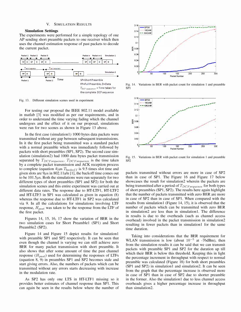
Figures 14, 15, 16, 17 show the variation of BER in the two simulation cases for Short Preamble 1 (SPl) and Short Preamble2 (SP2).
Figure 14 and Figure 15 depict results for simulation 1 with preamble SPI and SP2 respectively. It can be seen that even though the channel is varying we can still achieve zero BER for many packet transmission with short preamble. It also shows that after some amount of time the past channel response (Hpast) used for determining the responses of LTFs (equation 8, 9) in preambles SPI and SP2 becomes stale and start giving errors. Also, the numbers of packets which can be transmitted without any errors starts decreasing with increase in the modulation rate.
As SP2 has only one LTS in HT-LTFI missing so it provides better estimates of channel response than SP 1. This can again be seen in the results below where the number of
0.16F=--=-;-----.------,------,---.----:=:-:-:::l -BPSK
. _ . _ , .. , .. ,-, ....... ,"", ... , .. ' .. '_ .... '_, .. ,_, .. ' .. . . ' _ , .. ' �, 0.14 ........ ·1 6QAM _ -
., ...... , ............. , .. .. ·'·"64OAM ",',.
/'/' .,,",.,,
'''''''''''
'
''' .. ''''' .•.
0.12
0.1
ffiO.OB i �
· : : /': " i " 0
0 50 100 150 Packet Number
200 250 300
Fig. 14. Variations in BER with packet count for simulation 1 and preamble SPI
Packet Number
Fig. 15. Variations in BER with packet count for simulation 1 and preamble SP2
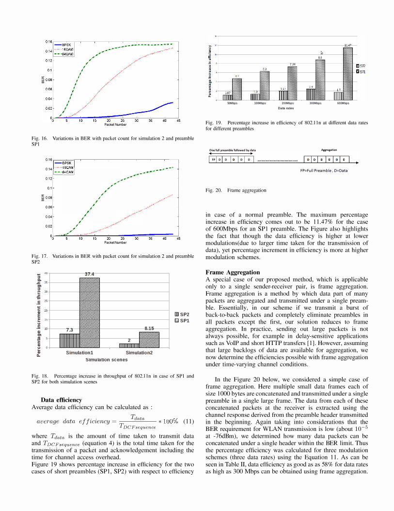
packets transmitted without errors are more in case of SP2 than in case of SPI. The Figure 16 and Figure 17 below showcases the result for simulation2 wherein the packets are being transmitted after a period of T DC F sequence for both types of short preambles (SPl, SP2). The results here again highlight that the number of packets transmitted with zero BER are more in case of SP2 than in case of SPI. When compared with the results from simulation 1 (Figure 14, 15), it is observed that the number of packets which can be transmitted with zero BER in simulation2 are less than in simulation I. The difference in results is due to the overheads (such as channel access overhead) involved in the packet transmission in simulation2 resulting in fewer packets than in simulation 1 for the same time duration.
Taking into considerations that the BER requirement for WLAN transmission is low (about 10-5 at -76dBm), then from the simulation results it can be said that we can transmit packets with preamble SPI and SP2 for the duration up till which their BER is below this threshold. Keeping this in light the percentage increment in throughput with respect to normal preamble was calculated (Figure 18) for both short preambles (SPI and SP2) in simulation 1 and simulation2. It can be seen from the graph that the percentage increase is observed more in case of SPI than in case of SP2 due to shorter preamble in the former. Also the simulation 1 due to less channel access overheads gives a higher percentage increase in throughput than simulation2.
Packet Number
Fig. 16. Variations in BER with packet count for simulation 2 and preamble SPI
: :: IF"=",,=,,,=� :=�;"" K 9', I --.- --.--..---r----.--.-, .'
, .-.-,.-
, .'
, .-.• -,,---,
- ' - "64� I .. ,., .. 0.12 ,.",'" ; ' ..... 0.1 '"
w 0.08 '" 0.06
0.04
0.02
" " " " ",/' .. ,"""""',.,"""."""'"''
///:' . . ,. " " ����--�10��15�� 2�0--2�5--�30��3�5 ��4�0��45
Packet Number
Fig. 17. Variations in BER with packet count for simulation 2 and preamble SP2
� � �-----1 ���----------� :::I C. .c 35+--C) :::I e "' +--.; .: 25 �
; 20+---E � l� ., .5 l0t---�'1 Q) C) J!I 5 C CI)
8.15
2 !::! 0 CI) a. Simulationl Simulation2
Simulation scenes
IDJ SP2 r:r::I SPl
Fig. 18. Percentage increase in throughput of 802.11n in case of SPI and SP2 for both simulation scenes
Data efficiency Average data efficiency can be calculated as :
d ii' . Tdata (Jf average ata e zczency =
T * 100/0 (11)
DCFsequence
where Tdata is the amount of time taken to transmit data and TDCFsequence (equation 4) is the total time taken for the transmission of a packet and acknowledgement including the time for channel access overhead. Figure 19 shows percentage increase in efficiency for the two cases of short preambles (SPl, SP2) with respect to efficiency
50Mbps lOOMbps 200Mbps Data rates
JOOMbps 600Mbps
Fig. 19. Percentage increase in efficiency of 802.11n at different data rates for different preambles
One full preamble followed by data II �
I ,pi 0 I 0 10 I 0 I 0
Fig. 20. Frame aggregation
Aggregation
FP=Full Preamble, D=Data
in case of a normal preamble. The maximum percentage increase in efficiency comes out to be 1l.47% for the case of 600Mbps for an SPI preamble. The Figure also highlights the fact that though the data efficiency is higher at lower modulations(due to larger time taken for the transmission of data), yet percentage increment in efficiency is more at higher modulation schemes.
Frame Aggregation A special case of our proposed method, which is applicable only to a single sender-receiver pair, is frame aggregation. Frame aggregation is a method by which data part of many packets are aggregated and transmitted under a single preamble. Essentially, in our scheme if we transmit a burst of back-to-back packets and completely eliminate preambles in all packets except the first, our solution reduces to frame aggregation. In practice, sending out large packets is not always possible, for example in delay-sensitive applications such as VoIP and short HTTP transfers [1]. However, assuming that large backlogs of data are available for aggregation, we now determine the efficiencies possible with frame aggregation under time-varying channel conditions.
In the Figure 20 below, we considered a simple case of frame aggregation. Here multiple small data frames each of size 1000 bytes are concatenated and transmitted under a single preamble in a single large frame. The data from each of these concatenated packets at the receiver is extracted using the channel response derived from the preamble header transmitted in the beginning. Again taking into considerations that the BER requirement for WLAN transmission is low (about 10-5 at -76dBm), we determined how many data packets can be concatenated under a single header within the BER limit. Thus the percentage efficiency was calculated for three modulation schemes (three data rates) using the Equation 1l. As can be seen in Table II, data efficiency as good as as 58% for data rates as high as 300 Mbps can be obtained using frame aggregation.

TABLE II. PERCENTAGE EFFICIENCY UNDER FRAME AGGREGATION FOR DIFFERENT DATA RATES
Data rates in Mbps Percentage efficiency
50 98.3
200 88.3
300 58.9
VI. RELATED WORK
A lot of work have been done to increase WLAN throughput. Here we discuss a few relevant papers.
In their paper Eugenio Magistretti et al. [1] tried to improve Wi-Fi throughput by decreasing the slot time. In their work they proposed extensive hardware changes to implement speculative preamble which would bring down the slot time from standard 9fJ seconds to 800 nano seconds. By the use of speculative preamble they propose to begin transmission before the expiration of contention window thus bringing down clear channel access time and ultimately slot time. A 100% increase in efficiency is claimed in the paper.
In another paper, Magistretti et al. [12] reduced control overhead in WiFi by using symbol sequences instead of fullfledged packets to communicate control information.
Hakyung Jung et al. [10] proposed a solution to increase the data rate in WLAN transmission on the basis of modulation rate used in the transmission of ACK. REACT (Rate adaptation using coherence time) implements an idea wherein the receiver upon judging the condition of channel, from the BER of the data received, would adapt the modulation rate of its ACK. This in turn would signify the transmitter of the improvement or deterioration of channel conditions on the basis of which the transmitter would alter its data rate.
Frederico et al. [13] proposed method to dynamically tune 802.11's exponential backoff algorithm and contention window parameter in the DCF mode operation.
Wang et al. [14] present a novel preamble design that reduces PHY overheads by transmitting data in the preamble part itself and hence making more efficient utilization of bandwidth.
Fang et al. [15] propose FICA which allows different nodes to use different OFDM sub-channels to improve performance. Nodes use frequency domain backoff to contend for subchannels.
Our work is, to the best of our knowledge, the first to propose reusing old channel state information from overheard preambles in the 802.11 context.
VII. CONCLUSIONS AND FUTURE WORK
We have presented a proof-of-concept of a novel idea to reuse channel state information learned in the recent past to decipher packet data. This idea allowed us to reduce the size of preambles of packets thereby reducing preamble overhead.
Several issues remain to be studied in future work. We have not presented a protocol to estimate the coherence time of the channel. Efficient protocols must be developed for this purpose. Further, our ideas can be evaluated in a setting which simulates both the PHY and MAC layers of
802.11. We are, however, currently unaware of any simulator which implements both PHY and MAC layers of 802.11 in detail. Combining our method with methods that reduce other overheads such as channel access overheads is also part of our future work.
Also, using software defined radios would be a good way of determining the feasibility of this idea. They would help in simulating a more realistic and real life scenario which might not be possible in computer simulations.
REFERENCES
[1] E. Magistretti, K. K. Chintalapudi, B. Radunovic, and R. Ramjee, "WiFi-nano: reclaiming WiFi efficiency through 800 ns slots," in Proceedings of the 17th annual international conference on Mobile computing and networking, ser. MobiCom '11, 2011, pp. 37-48.
[2] T. Paul and T. Ogunfunmi, "Wireless Ian comes of age: Understanding the IEEE 802.11n amendment," Circuits and Systems Magazine, IEEE, vol. 8, no. 1, pp. 28-54, 2008.
[3] T. Ogunfunmi, "IEEE 802.lI n WLAN file update." [Online]. Available: http://www.mathworks.inlmatlabcentrallfileexchangeI26232-ieee-802-11n-wlan-file-update
[4] "802. lI n signal structure." [Online]. Available: http://wireless.agilent.comlwireless/helpfiles/n7617a.htm
[5] "IEEE draft standard for information technology - telecommunications and information exchange between systems - local and metropolitan area networks - specific requirements - part 11: Wireless LAN medium access control (mac) and physical layer (phy) specifications," IEEE
P802.11-REVmaID89.0, pp. 1-1230, 2010.
[6] J. Heiskala and J. Terry, OFDM Wireless LANs: A Theoretical and
Practical Guide. SAMS, 2001, pp. 51-84.
[7] I. Ramachandran and S. Roy, "Clear channel assessment in energyconstrained wideband wireless networks," Wireless Communications, IEEE,
vol. 14, no. 3, pp. 70-78, 2007.
[8] Z. -w. Zheng, "Design and implementation of channel estimation and channel updating for OFDM-based WLAN receivers," in Microwave,
Antenna, Propagation and EMC Technologies for Wireless Communications, 2009 3rd IEEE International Symposium on, 2009, pp. 1192-1196.
[9] G. Breit, "Coherence time measurement for TGac channel mode\," Doc.1EEE 802.11-0911173r1, 2009.
[10] H. Jung, T. T. Kwon, K. Cho, and Y. Choi, "REACT: Rate adaptation using coherence time in 802.11 WLANs," Computer Communications, vol. 34, no. 11, pp. 1316 - 1327, 2011. [Online]. Available: http://www.sciencedirecLcom/science/article/pii/SO 140366411 000594
[I I ] Y. Erceg, L. Schumacher, and P. Kyritsi et aI., "IEEE 802.11 wireless Ian tgn channel models," Doc.IEEE 802. 11-031940r4, May 10, 2004.
[12] E. Magistretti, O. Gurewitz, and E. W. Knightly, "802.11 ec: collision avoidance without control messages," in Proceedings of the 18th annual international coriference on Mobile computing and networking. ACM, 2012, pp. 65-76.
[13] F. Cali, M. Conti, and E. Gregori, "Dynamic tuning of the IEEE 802.11 protocol to achieve a theoretical throughput limit," Networking,
1EEEIACM Transactions on, vol. 8, no. 6, pp. 785-799, 2000.
[I 4] Y. Wang, J. Oostveen, A. Filippi, and S. Wesemann, "A novel preamble scheme for packet-based OFDM WLAN," in Wireless Communications and Networking Conference, 2007. WCNC 2007. IEEE, 2007, pp. 1481-1485.
[I 5] J. Fang, K. Tan, Y. Zhang, S. Chen, L. Shi, J. Zhang, Y. Zhang, and Z. Tan, "Fine-grained channel access in wireless lan," Networking, IEEEIACM Transactions on, vol. 21, no. 3, pp. 772-787, 2013.