oval gear flowmeter electronic model 025 / 1” …€¦ · page 1 of 13 instruction manual to the...
TRANSCRIPT

Page 1 of 13
INSTRUCTION MANUAL
To the Owner
OVAL GEAR FLOWMETER ELECTRONIC MODEL 025 / 1”
Type ‘CR’ for Corrosive Applications
PLEASE READ THIS SAFTEY INFORMATION CAREFULLY BEFORE USE. Read and retain this instruction manual to assist you in the operation and maintenance of this product. If you have any problems with the meter, refer to the maintenance and trouble shooting sections of this manual. This manual contains connection and operating in-structions for meters with Pulse outputs. Models with a Liquid Crystal Display have an addi-tional LCD instruction manual supplied. If you need further assistance, contact your local representative or distributor for advice.
This Flow Meter has incorporated the oval rotor prin-cipal into its design. This has proven to be a reliable and highly accurate method of measuring flow. Exceptional repeatability and high accuracy over a wide range of fluid viscosities and flow rates are features of the oval rotor design. With a low pressure drop and high pressure rating oval rotor flow meters are suitable for both gravity and pump (in line) applications. This instruction manual covers pulse meters con-structed in Aluminium or Stainless Steel. Also in-cluded are the high pressure versions of this model.
INST-CR025P_R5
09/2013

Page 2 of 13
CAUTION
Important Information
Operating Principle
Installation Procedure
WARNING
Before use, confirm the fluid to be used is com-patible with the meter. Refer to Industry fluid compatibility charts or consult your local rep-resentative for advice. To prevent damage from dirt or foreign matter it is recommended that a Y or Basket type 60 mesh strainer be installed as close as possible to the inlet side of the meter. Contact your local repre-sentative for advice.
When a strainer is installed it should be regularly inspected and cleaned. Failure to keep the strainer clean will dramatically effect flow meter performance.
To prevent damage caused by air purge slowly fill the meter with fluid. To reduce pressure build up turn off the pump at the end of each day. Maintenance can be carried out to the liquid crystal displays and pulse units without removing or isolat-ing the meter from the line. When maintenance to any other part of the meter is required, the meter must be isolated and the line pressure reduced. The reed switch pulse unit can cause inaccurate rate counts when used with high speed counters. It is advised that a debounce circuit be used. Contact your meter distributor for further information.
CAUTION
CAUTION
When fluid passes through the meter the rotors turn, as shown below. The magnets which are located in the rotors will pass across the pulser circuit board (containing either Reed switches or Hall Effect sensors). A signal is generated which is then sent by the Pulse Circuit Board (PCB) to the relevant LC display or receiving instrument..
1) It is recommended that when setting up pipe work for meter installations a bypass line be included in the design. This provides the facility for a meter to be removed for maintenance without interrupting production. (see figure above) 2) Use thread sealant on all pipe threads. 3) For pump applications ensure pipe work has the appropriate working pressure rating to match the pressure output of the pump. See Meter Specifications section for further details. 4) Install a wire mesh strainer, Y or basket type 60 mesh (250 micron), as close as possible to the inlet side of the meter. 5) Ensure that the meter is installed so that the flow of the liquid is in the direction of the arrows embossed on the meter body. 6) The meter can be installed in any orientation as long as the meter shafts are in a horizontal plane. (Refer to figures to the right for correct installation) The register assembly may be orientated to suit the individual. Note: Incorrect installation can cause premature wear of meter components. 7) Do not over tighten meter connections. Note: Incorrect installation can cause premature wear of meter components. 8) It is important that after initial installation you fill the line slowly, high speed air purge could cause damage to the rotors. 9) Test the system for leaks. 10) Check the strainer for swarf or foreign material, after the first 200 litres check periodically, particularly if the flow rate decreases.

Page 3 of 13
Maintenance Procedures
Ensure that the fluid supply to the meter is dis-connected, and the line pressure is released be-fore disassembly, with the exception for repair or maintenance to the LC Display or PCB where there is no necessity to isolate the meter from flow. Refer to the exploded parts diagram on subsequent pages for item numbers. 1) Pulse Caps Models: Undo the conduit connector, remove pulse cap (item 9) and remove the wires from the pulse terminal board (item 5). 2) Standard LC Display: Mark the display orientation with a marking pen, unscrew the four large screws on top of the LC Display. Carefully separate the LC Display from the plastic housing and disconnect the wires from the pulse terminal block. (Refer to additional LCD instruction manual accompanying these instructions). Remove the mounting adaptor plate and gasket. 3) Loosen the cap head screws (Item 7) that hold down the meter cap (Item 4), remove the screws, washers and lift off the cap. 4) Remove the o-ring (Assembly Item 2) from the o- ring groove in the meter cap (Assembly Item 4). 5) Remove rotors (Item 3).
Disassembly
Reassembly
1) Before reassembling check the condition of the rotors (replace if necessary). 2) Check that the smooth side of the rotors (not the plug side) is facing you when inserting the rotors, the smooth side of the rotor is the magnet side. There is no difference between rotor one or rotor two. 3) Replace the rotors (Item 3) onto the shafts at 90 degrees to each other (refer Fig) and check their operation by turning either of the rotors. If the rotors are not in mesh correctly or do not move freely, remove one of the rotors and replace correctly at 90 degrees to the other rotor. 4) Re-check the operation of the rotors 5) Replace the o’ring (Item 2) into groove in the meter cap, if the o’ring has grown or is damaged in any way replace it with a new part. 6) Replace the meter cap making sure that the locating pin in the body lines up with the hole in the meter cap.
7) Insert the cap head screws (Item 7) and tighten in a diagonal sequence 1, 3, 2, 4, etc. 8) The replacement of cables and connectors are a reversal of the disassembly procedure, replace conduit fitting if required. When replacing the Standard LC Display confirm the orientation marks made on disassembly are aligned then screw the register into place. 9) Test the meter by turning the rotors with a finger or by applying very low air pressure (no more than a good breath) to one end of the meter, before returning the meter to the line.
Page 4 of 13
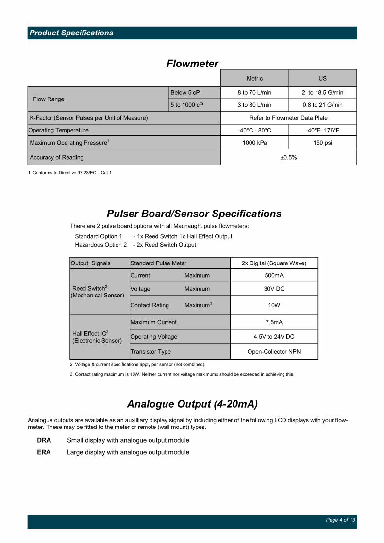
Product Specifications
Analogue Output (4-20mA)
Analogue outputs are available as an auxilliary display signal by including either of the following LCD displays with your flow-meter. These may be fitted to the meter or remote (wall mount) types.
DRA Small display with analogue output module
ERA Large display with analogue output module
Flowmeter
Metric US
Flow Range Below 5 cP 8 to 70 L/min 2 to 18.5 G/min
5 to 1000 cP 3 to 80 L/min 0.8 to 21 G/min
K-Factor (Sensor Pulses per Unit of Measure) Refer to Flowmeter Data Plate
Operating Temperature -40°C - 80°C -40°F- 176°F
Maximum Operating Pressure1 1000 kPa 150 psi
Accuracy of Reading ±0.5%
1. Conforms to Directive 97/23/EC—Cat 1
Pulser Board/Sensor Specifications There are 2 pulse board options with all Macnaught pulse flowmeters:
Standard Option 1 - 1x Reed Switch 1x Hall Effect Output
Hazardous Option 2 - 2x Reed Switch Output
Output Signals Standard Pulse Meter 2x Digital (Square Wave)
Reed Switch2 (Mechanical Sensor)
Current Maximum 500mA
Voltage Maximum 30V DC
Contact Rating Maximum3 10W
Hall Effect IC2 (Electronic Sensor)
7.5mA Maximum Current
Operating Voltage 4.5V to 24V DC
Transistor Type Open-Collector NPN
2. Voltage & current specifications apply per sensor (not combined).
3. Contact rating maximum is 10W. Neither current nor voltage maximums should be exceeded in achieving this.

Page 5 of 13
Troubleshooting Guide
Problem Cause Remedy
Fluid will not flow through meter
a) Foreign matter blocking rotors b) Line strainer blocked c) Damaged rotors d) Meter connections over tightened e) Fluid is too viscous
a) Dismantle meter, clean rotors (strainer must be fitted in line) b) Clean strainer c) Replace rotors (Strainer must be fitted in line) d) Re-adjust connections e) See specifications for maximum viscosity
Reduced flow through meter
a) Strainer is partially blocked b) Fluid is too viscous
a) Clean strainer b) See specifications for maximum viscosity
Meter reading inaccurate
a) Fluid flow rate is too high or too low b) Air in fluid c) Excess wear caused by incorrect instal-lation
a) See specifications for minimum and maximum flow rates b) Bleed air from system c) Check meter body and rotors. Replace as required. Refer to installation instructions
Meter not giving a pulse signal
a) Faulty hall effect sensor b) Faulty reed switch c) Magnets failed
a) Replace PCB Board b) Replace PCB Board c) Replace magnets
LCD register not working
a) Battery not connected properly b) Battery flat c) Faulty wiring connections d) Faulty LC Display e) Faulty connection from LC Display
a) Check battery connections b) Replace battery c) Check wiring for loose or faulty connections d) Replace LC Display e) Check wiring connections
Note: Consult the following instruction sheets if the flow meter is fitted with an LCD Display. Display Part Number: DR DRA ER ERB ERA ERS Instruction Sheet: DR013 DR014 MS574 MS392 MS476 MS351
Reed
Switch 1
Reed Switch 2
Reed Switch
Hall
Effect
* Macnaught pulser boards are not fitted with a pull up resistor. Consult sensor specifications on page 4 for selection of appropriate resistance.
Pull up Res Ω*
Note: Reed Switches are not polarity sensitive.
Pulser Wiring Diagram
Please read this information carefully before installation
Hall Effect: Hall effect sensors require an external pull up resistor to be fitted by the installer for correct operation. Powering a Hall effect sensor without a resistor wired between the supply voltage and the signal line will result in damage to the sensor. Reed Switch: In order to protect the reed switch from over current, and to maximise life expectancy, we recommend limiting the current through the switch by fitting a series resistor in between the signal leg and the PLC/signal sensing device.
V1+
V1-
GND
SIG2
Vcc
V1+
V1-
V2+
V2-
NOT USED
Standard. Option 1 Hazardous. Option 2
Series Res Ω**
** Macnaught pulser boards are not fitted with a current limiting resistor. For 12VDC we recommend a1kΩ resistor. For 24VDC, we recommend a 1.8k-2.2kΩ resistor.
1
2
3
4
5
Series Res Ω**
Series Res Ω**
1
2
3
4
5

Page 6 of 13
Spare Part Diagram
Parts Identification
Item No. Part Description
1 Meter Body
2 0-Ring
3 Rotors
4 Meter Cap
5 Printed Circuit Board
6 PCB Mounting Screws
7 Meter Cap Screws
8 Pulser Cap Gasket
9 Pulser Cap
10 Pulser Cap Screws

Page 7 of 13
PKit — Size — 1 (Reed/Hall) 2 (Reed/Reed)
CR 025 — 1 S 2
Coding Sequence
Customer Model Number
Spare Parts Kits
Pulser Kit - (P Kit)
There are 4 Spare Kit options available for the purchase of replacement components:
Pulser Kit (PKit) - Replacement PCB.
Rotor Kit (RKit) - Complete Rotor assembly
Seal Kit (SKit) - Complete set of O-Rings/Gaskets Spare Kit Coding Procedure. 1. Determine what type of Spare Parts Kit is required (e.g. Rotor Kit) 2. Use the ‘Coding Sequence’ to construct a part number according to the meter type.
Order Number Components Qty Items
e.g PKit – 025 – 2 PCB 1 5
Mounting Screws 2 6
Kit Components

Page 8 of 13
SKit — Type Size — 1/2 = P 3/4/5 = M
CR 025 — 1 S 2 Customer Model Number
Seal Kit - (S Kit)
Rotor Kit - (R Kit)
Customer Model Number
Order Number Components Qty Items
Pulser Cap Gasket 1 e.g SKit – CR025 – P
8
Meter Body O-Ring 1 2
Order Number Components Qty Items
Complete Rotor Assembly 1 set
e.g RKit – CR025 – SP
3
Meter Body O-Rings 1 2
Meter Cap Screws 6 7
RKit — Type Size Rotor Type
1/2 = P 3/4/5 = M
—
CR 025 — 1 S 2
Kit Components
Kit Components
Coding Sequence
Coding Sequence

Page 9 of 13
Wetted Parts
Component Type 'CR'
Meter Body PPS
Meter Cap PPS
Rotor Shafts Hast C
Rotors - Standard PPS
O-Rings K
PPS - Polyphenylene Sulphide
PVDF - Polyvinylidene Flouride
PTFE - Polytetrafluoroethylene
Hast C - Hastelloy C ™
K - FEP/PTFE Encapsulated
100%
50%
High Viscosity Fluids Pressure Loss and Maximum Flows

Page 10 of 13
Meter Dimensions

Page 11 of 13
Notes
WEEE Directive - Waste Electrical and Electronic Equipment
The WEEE Directive requires the recycling of waste electrical and electronic equip-
ment in the European Union.
Whilst the WEEE Directive does not apply to some of Macnaught’s products, we sup-
port its policy and ask you to be aware of how to dispose of this product.
The crossed out wheelie bin symbol illustrated and found on our products signifies that
this product should not be disposed of in general waste or landfill.
Please contact your local dealer national distributor or Macnaught Technical Services
for information on product disposal.

Page 12 of 13