outline - sintef · pdf fileflow assurance trial 1 24 20-inch pipe, 22mm wt, with brick,...
TRANSCRIPT


2
• Introduction
• Flow assurance challenges and needs
• Initial Statoil and Tracerco cooperation
on developing/testing detection tools
• Examples of field tests
• DiscoveryTM - Subsea Pipeline
Visualisation
• Introduction to the technology
• Trials and scan images
• Summary and Conclusion
Outline

3
• Hydrate restrictions in production systems
• No reliable detection tools, especially for subsea use
• Needs for high accuracy detection tools
• Cooperation between Statoil and Tracerco over last 10 years
– To develop detection technology
– Primary goal was FA applications
– Application areas have expanded
Introduction

• Plug location
• Plug characteristics
– Liquid pockets, wax depositions,
hydrate restrictions, scale etc.?
• Information important for
– Safety considerations
– Evaluation of remediation solutions
4
Flow Assurance challenges

6
Subsea Subsea template
template
mimicmimic
Flowline Flowline
mimicmimic
66”” test test
sectionsection
Gas/liquidGas/liquid
separatorseparator
KO drumKO drum
Flare lineFlare line
Gas Gas feedfeed
FiberFiber optics in optics in
all test sectionsall test sections
5
Statoil's Flow Assurance Pilot

Tomography map with liquid filled pipe section
Tomography technique used during
hydrate detection trials
Statoil's Flow Assurance Pilot Plant
6
Tomography map after draining

100 mm
7
Topside field measurements
Tomography applications

8
Single gamma applications
Subsea field trial

Discovery
The technology

Discovery Pipeline Visualisation
• Tracerco DiscoveryTM is the world’s first Subsea CT Scanner, a
revolutionary non-intrusive technology for inspection of subsea
pipelines.
• It is specifically targeted for the inspection of unpiggable,
coated pipelines
10
Subsea Integrity
Flow Assurance

Same principle as medical CAT scanner
• Reconstructs image of a target from a series of projections
• One gamma radiation source and a large number of detectors
The same concept has been taken from the medical field to design,
implement and deploy a scanner for subsea pipelines
Discovery Principle

Discovery
Initial Prototype Results

Initial Lab Prototype Results
10-inch Pipe, 20mm wt, 50mm PU coating
SAMPLE
13

Pipe-in-pipe Systems
Assess integrity of inner and outer pipes
14

SAMPLE
Caissons and Pipe Bundles
Assess integrity of internal flowlines as well as the outer pipe
Gas Riser Oil Riser
15

Discovery
The Instrument

• Completely non intrusive – No need to remove coating
– No need to stop production
• Wide range of pipes – 6 to 27 inch.
– Integrity and Flow Assurance
– Pipe-in-pipe and caissons
• 10000 ft / ~3000m Depth
• X/Y resolution close to 1mm
• Real-time Data Acquisition on the vessel
– Images continuously updated every 20-30 seconds
Discovery _ specification overview

• Crawler
– Instrument automatically
advances on the pipe
• Scanning speed
– ~2-3 ft/h for low resolution
– ~0.5 ft/h for high
resolution
Discovery _ specification overview

Discovery
Underwater Trials

First Subsea Trial - Bergen, April 2013
20

2nd Subsea Trial – Scotland, 08/13

Customer Trial Results
• Test pieces supplied by customers, for proof of capability prior to
offshore inspection project

Tracerco Discovery
Customer Trial Results – Flow Assurance

Flow Assurance Trial 1
24
20-inch Pipe, 22mm wt, with brick, thermalite block, 2 sand bags, half filled
with water
Feature Description Dimensional Information
1 Known feature Object of size 100mm wide x 50mm high, density ~2.4g/cc
2 Known feature Object of size 95mm wide x 210mm high, density ~0.9g/cc
3 Known feature Freeform object of approx. size 100mm x 90mm high, density ~1.9g/cc
4 Known feature Freeform object of approx. size 100mm x 90mm high, density ~1.9g/cc
5 Known feature Fluid filled to approx. 50% of volume, density ~1g/cc
6 Unknown feature Gas pocket of approx. size 70mm wide x 35mm high
The tomogram produced correctly identifies each of the objects and can display the appropriate relative densities and shape definition.

• 273mm OD, 15.9mm
WT
• 10mm internal plastic
lining
• Manufactured blister to
simulate damage
Flow Assurance Trial 2 8-inch water injection line with plastic liner

TEST Detect small gas channel
openings in blocked
pipelines
WHY Assess possibility of gas
communication between
different sections
MODEL • 12 inch Pipe-in-Pipe
• Blockage and gas as
density-equivalent plastic.
Then inserted in the pipe
and scanned
Flow Assurance Trial 3

Trial 3 – 30 seconds (1 lap)
Most channels detected after just 1 lap!
MODEL RECONSTRUCTION

Trial 3 – 1 minute (2 laps)
Getting Sharper. Now all channels are visible.
MODEL RECONSTRUCTION

Trial 3 – 5 minutes (10 laps)
Getting Sharper. All channels well visible.
MODEL RECONSTRUCTION
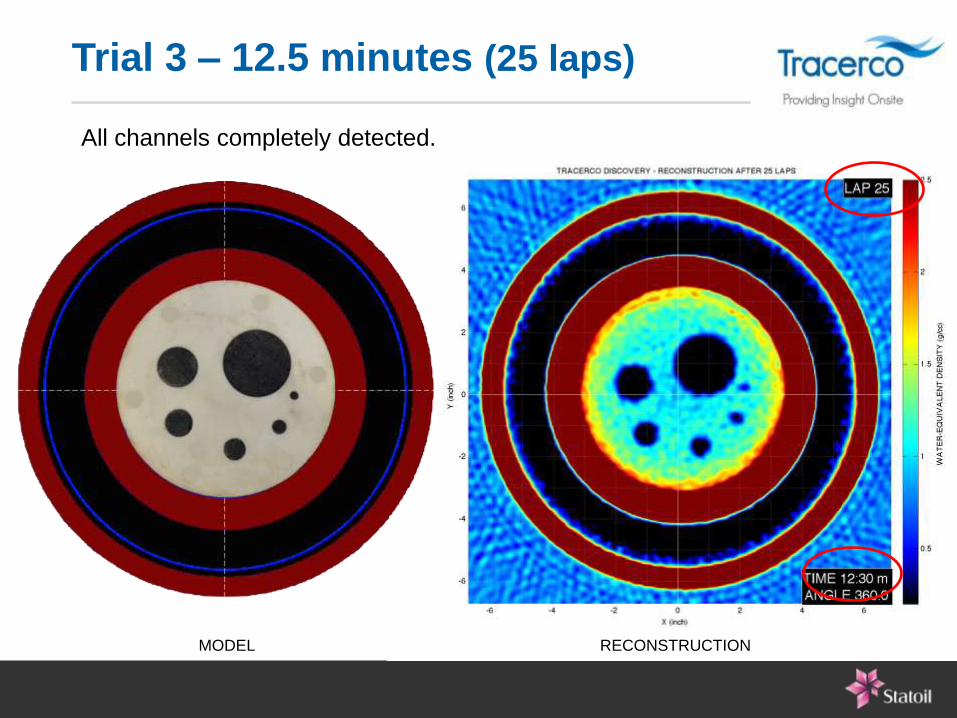
Trial 3 – 12.5 minutes (25 laps)
All channels completely detected.
MODEL RECONSTRUCTION

TEST Detecting gas pressure
differences in blocked
pipelines channels
WHY Assess gas communication
(HP/LP) between sections
of pipeline
MODEL • Same Pipe-in-Pipe
• Blockage and as density-
equivalent plastic to
asphaltene or wax.
• HP/LP gas as density-
equivalent foam (0.1/0.2
g/cc)
LOW
PRESS
GAS ~0.1
g/cc
HIGH PRESS.
GAS ~0.2 g/cc
Flow Assurance Trial 4

Trial 4 – 12.5minutes (25 laps)
Successful detection of gas density differences in channels.
MODEL RECONSTRUCTION 0.1 g/cc
0.2 g/cc

Tracerco Discovery
Customer Trial Results – Pipeline Integrity
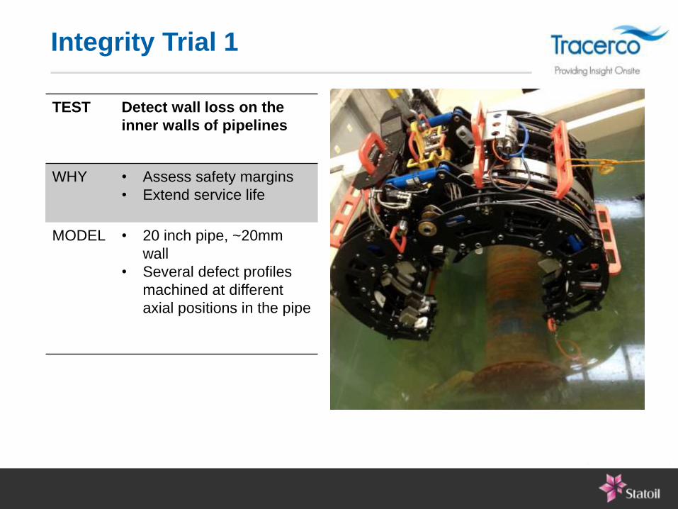
Integrity Trial 1
TEST Detect wall loss on the
inner walls of pipelines
WHY • Assess safety margins
• Extend service life
MODEL • 20 inch pipe, ~20mm
wall
• Several defect profiles
machined at different
axial positions in the pipe

DRAWINGS RECONSTRUCTION
6+1 localized defects and 2 scallops to model wall loss
Integrity Trial 1

DRAWINGS RECONSTRUCTION
Trial 1 – 30 seconds (1 lap)
Early detection of most defects and scallops in 30 seconds.

DRAWINGS RECONSTRUCTION
Trial 1 – 5 minutes (10 laps)
Image getting sharper. All defects clearly visible.

DRAWINGS RECONSTRUCTION
Trial 1 – 20 minutes (40 laps)
High resolution image. All defects visible and quantifiable.
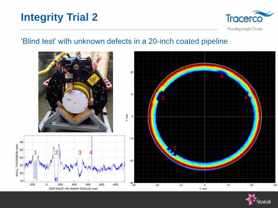
‘Blind test’ with unknown defects in a 20-inch coated pipeline
1 2 3 4 1
2
3
4
Integrity Trial 2

TEST Detect voids and broken
strands in flexible risers
WHY • Assess safety margins
• Extend service life
MODEL • 12-inch flexible riser
• 1 strand segment was
removed from the outer
tensile armor.
Integrity Trial 3

Trial 3 – 30 seconds (1 lap)
MODEL RECONSTRUCTION
Indication of broken strand at the first lap (30 seconds).

Test 4 – 12.5 minutes (25 laps)
MODEL RECONSTRUCTION
Image getting sharper. More detail on the inner carcass and all other layers.
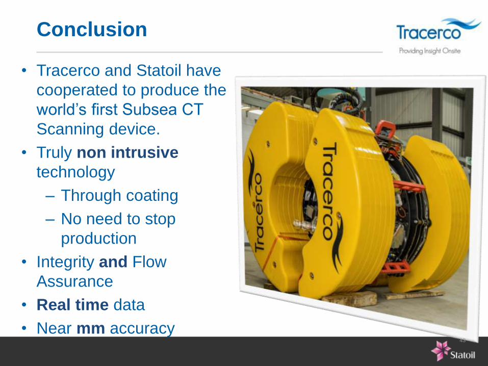
• Tracerco and Statoil have
cooperated to produce the
world’s first Subsea CT
Scanning device.
• Truly non intrusive
technology
– Through coating
– No need to stop
production
• Integrity and Flow
Assurance
• Real time data
• Near mm accuracy
Conclusion
43
