out-of-plane buckling of solid rib arches braced with
TRANSCRIPT

109
Proc. of JSCE,
No. 191, July 1971
OUT-OF-PLANE BUCKLING OF SOLID RIB ARCHES
BRACED WITH TRANSVERSE BARS
Tatsuro SAKIMOTO* and Yoshio NAMITA* *
SYNOPSIS
The out-of-plane buckling of a circular arch is studied. The arch is composed of two main ribs braced with transverse bars and is subjected to uniformly distributed radial forces (see Fig. 1) . The analysis is carried out by means of transfer matrix method and both the field matrix of arched rod and point matrix are presented. Attention is
given to the influences of the flexural rigidity, the number and the location of bracing bars on the buckling strength of arches. Buckling coefficients for various types of arch are calculated by trial and error method. Useful suggestions about the bracing method are obtained from the results of computations. The theoretical analysis is followed
by model tests in order to verify the results of computation.
1 . INTRODUCTION
The out-of-plane buckling of arches means, in this paper, an elastic buckling which occurs with both lateral flexure and torsion simultaneously under mainly axial thrust. As is well known, the lateral-torsional buckling is one of dominant insta-bility problems of slender arch bridges. In order to design a slender arch bridge as an economical and safe structure, it is necessary to give it enough lateral stability. In ordinary arch bridges of parallel double arches, the two arched ribs are usually braced either with a truss or with transverse bars in order to give them a sufficient lateral rigidity. These bracings will be more effective for the dou-ble arches which are not stable when considered
separately. L. Ostlund3) and G. Wastlund4) investigated late-
ral stability of bridge arches braced with transverse bars in comparison with the lateral buckling of
straight bars braced with battens . Various factors about the transverse bars are discussed and many important qualities are reported . The equation for the deformation of the arch, hewever, is not des-cribed with enough strictness.
S. Kuranishi2) studied the lateral-torsional buc-kling of two-hinge circular arch bridges, composed of two main arched girders, cross beams and lateral bracing, loaded by uniformly distributed vertical forces. Buckling coefficients of arches with flexible cross bars are computed by means of strain energy method. Besides, a reduction factor for torsional
rigidity of the main arched girder due to the flexi-bility of transverse bars are obtained, but effects due to discontinuity of cross bars are not conside-red.
One of the authors1) presented a fundamental equation for deformation of a curved rod and em-
ployed it to an analysis of out-of-plane buckling of single arch. In this paper, employing transfer matrix method to this fundamental equation, the authors describe the out-of-plane buckling of double arches braced with transverse bars. By means of
this method, the buckling problem of double arches braced with arbitrary number of transverse bars in arbitrary location can be analyzed.
2. THEORETICAL STUDY
( 1 ) Assumptions
A part of an arch cut off by two adjacent points will be called an element of arch, and the displace-ments of the arches are described by the position of the centroids of their cross sections. The funda-mental equations and extended formulations are derived on the following assumptions and idealiza-
tions. 1) The cross section of arched rib is bisymmetri-
cal and uniform within each element. The arch of nonuniform cross section may be analyzed after dividing it into uniform elements of adequate leng-th. 2) The warping rigidity and the effect of polar moment of inertia of arched ribs are disregarded. 3) Centroidal axes of the arches are inextensible.
* Graduate Student of Doctor Course, Graduate School
of Eng., Osaka Univ.* * Dr. Eng., Chief Research Engineer of Structural
Engineering Laboratory, Kobe Steel, Ltd., Formerly
Associate Professor of Civil Eng., Osaka Univ.

110 Sakimoto and Namita
(a) Double arches with transverse bars (b) Section t-t
4) Uniformly distributed radial forces, p, are loa-
ded at the centroids of cross sections of arched
ribs. 5) The forces do not change their directions
during the process of buckling (see Fig. 1 (b)).
6) The connection between arched ribs and trans-
verse bars are completely rigid. 7) Influence of
shear forces of transverse bars upon the buckling
load is disregarded.
( 2 ) Fundamental Equation and its Solution
Through consideration of an equilibrium of stress
resultants and external forces acting on the i-th
element of arched rib, following simultaneous diffe-
rential equations with respect to the lateral defle-
ction, α, and the torsional angle of cross section,
β, can be derived(see Ref,1) Eq.(30)).
That is,
( 1 )
where λi=pR3/EJi, mi=GIi/EJi and a prime supe-
rscript denotes one differentiation with respect to
angular coordinate, θ. The symbols EJi and GIi
are flexural rigidity about out-of-plane bending and
torsional rigidity of the i-th element, respectively.
General solutions of these governing equations take
different forms in compliance with the sign of 1-
λi/mi and are givenas follows:
for 1-λi/mi<0,
( 2 )
in which
(3)
and ( 4 )
(The solution for 1-λi/mi>0 can be obtai-
ned similarly, and omitted here.)
The symbols EJ0 and GI0 denote the fle-
xural rigidity and torsional rigidity of arched
rib at the arch crown, respectively. Out-of-
plane bending moment, M, torsional moment,
T, and shear force directed outwards the arch
plane, Q, are expressed in terms of displacements as follows
( 5 )
Substituting Eq. (2) into Eq. (5), and denoting the non-dimensional quantities, TRIGlo, MR/G10 and QR2/GI0 by the symbols T, M and Q, respe-ctively, Eq.(5) yields for 1-λi/mi<0,
(6)
( 3 ) Derivation of Field Matrix
First, 1et us take α, α',β, T, M and Q as the
elements of state vector Zi. That is,
( 7 )
in column vector form. This state vector, Zi, can be
related to the arbitrary constant, Ci, in matrix form
as follows :
( 8 )
Hence, the state vector of intersection points i - 1
and i will be expressed as
( 9 )
and
(10)
Solving Eq. (9) with respect to C and substituting
Fig. 1 General view

Out-of-Plane Buckling of Solid Rib Arches Braced with Transverse Bars 111
it into Eq. (10) yields
(11)
in which
(12)
and the subscripts L and R denote the left-hand side and the right-hand side of each intersection
point, respectively. For the convenience of expla-nation, let us express the field matrix in simple notations of square submatrices of order 3 as f oll-ows :
(13)
In the above discussion, attention is paid to one of
the double ribs. Then, in order to transfer the
quantities of both rib- I and rib-II simultaneously,
let us take the column vector,
(14)
as the state vector of the intersection point i,
where the symbols with the subscripts I and II
indicate the quantities with respect to rib- I and
rib-II, respectively. The overall relation between
the state vector of the intersection point i and that
of the intersection point i-1 will be given by
(15)
where
(16)
(4) Derivation of Point Matrix
First of all, let us imagine that the transverse
bars are connected to the arched rib as one of the
principal axes of transverse bar is always horizontal
(see Fig. 2(c)) and only the flexural rigidity with
(a)
(b) Section t-t
(c)
respect to the horizontal principal axis is considered
(let us call Type-V). Considering an arbitrary transverse bar cut off like what illustrated in Fig. 2, the relation between the flexural moments of transverse bar, ICIA and MB, and the deformationsof arched rib,α' and β, is shown as
in which the symbols a, Eli and -ei denote the distance between rib-I and rib-IL, flexural rigidity of i-th transverse bar and the angle between a horizontal line and the radius A-0, respectively. The equilibrium equations around the point A are
(18)
and QIR=QIL.As for the rib-II, in the same manner, the equili-
brium equations are :
(19)
and QIIR =_QIIL.The deformations α, α' and β will hold continuity
from the left-hand side to the right-hand side of
the intersection point i.Then, substituting Eq. (17)
into Eqs. (18) and (19), and introducing non-dime-
nsional quantity, ri = EJi/GI0•ER/a, yield
(20)
where
(21)
(22)
By the way, when the transverse bar is connected
to the arched rib ars one of the principal axes of
transverse bar is perpendicular to the longitudinal
axis of arched rib (let us call Type-P), the subm-
atrices, X and Y, of Eq. (21) will be obtainedFig. 2 Equilibrium around an i-th transverse
bar (Type-V)

112 Sakimoto and Namita
(a) (b)
(c)
( d )
as follows after a similar deduction shown above
(see Fig. 3) . In this case, both the flexural rigidity
with respect to x-axis, EJx, and that with respect
to y-axis. EJy, are considered. That is,
(23)
where
(24)
( 5 ) General Procedure of Transfer Matrix
Substituting Eq. (15) into Eq. (20) yields(25)
Repeating this procedure from point to point, the
state vector of the right-hand end of the arch can
be related to that of the left-hand end of the arch.
That is,
(26)
The matrix T takes usually a square matrix form of
order 12 and each element contains the buckling
coefficient, ă, as an unknown variable.
( 6 ) Boundary Conditions and Coefficient
Determinant
Two sorts of boundary conditions are considered.
First, when the both arch ends are rigidly fixed,
the boundary conditions are
(27)
Substituting Eq. (27) into Eq. (26) yields six hom-
ogeneous equations. For non-trivial solution of
these equations, the determinant of the coefficients
must be zero. Hence, the buckling condition is
(28)
The lowest positive value satisfying this condition
is the critical value of ă. Next, when the both arch
ends are hinged, the boundary conditions are
(29)
Substituting Eq. (29) into Eq. (26) , in the same
manner shown above, yields the buckling condition
of this case.
( 7 ) Numerical Procedure and Some Proble-
ms
The solution of Eq. (28) is obtained by means
of trial and error method as a value of ăj which
satisfies the relation D(λj)・D(λj+⊿ λ)≦0, where
⊿λ is the buckling-coefficient increment. As for the
magnitude of ⊿λ, the larger the better for shorte-
fling the computation time, but a large increment
involves a risk of failing to catch the positive-mini-
mum solution. Since even a small increment, ⊿λ,
will produce a large and sharp fluctuation of D(λ),
particularly in the region near the solution, special
attention must be paid in determining the magni-
tude of ‡™ƒÉ. Further, with respect to a certain com-
bination of the values, m and λ, the value of D(λ)
may fail to vanish at where it must be zero, owing
to the accumulated errors and lack of significant
digits. This deficiency was conquered by tracing
the value of D(λ) and the missing solutions were
presumed from the shape of the curve of D(λ).
Fig. 3 Transverse bar of Type-P
Table 1 Connecting direction of transverse bar
Type-V
Type-P
Type-L

Out-of-Plane Buckling of Solid Rib Arches Braced with Transverse Bars 113
( 8 ) Results and Consideration
Several numerical examples are shown below.
Since the symmetrical buckling of first mode will
give the smallest critical value, all computations
were performed about it. In these numerical
examples, the cross sections of the main ribs are
constant through the arch span and all the transverse
bars of each intersection point have same cross
section, and further central angle, θ0, of the arch
is right angle for all cases. Accordingly, νi=μi=1
(a) m=0.01
(b) m=0.1
(c) m=0.5
(d) m=1.0
and ri (i=1,2,…)=rt. Computation cases
are expressed as V-3 A-H or P-6B-F, etc..
The meaning of the first letter is explained
in Table 1. Type-P and Type-L are imagi-
ned to repesent the transverse bars of actual
arch bridges which mainly resist to torsion
of the arched ribsand lateral bracings of
actual arch bridges which resist only to late-
ral bending of the arched ribs, respecti vely.
The second letters mean the number and the
manner of arrangement of the transverse bars. The
last letter means the end condition of arches, fixed
or hinged. In the figures, the buckling coefficient,
λr, is defined as pRL2/EJ0, where L is arc-length of
the arch. The magnitude of m will be, in general,
(a) Fixed end (m=0.01)
(b) Hinged end (m=0.5)
V-3A-F
V-3B-F
V-3C-F
Fig. 4 Buckling coefficient for three transverse bars
(Fixed end)
V-6A-F
V-6B-F
Fig. 5 Buckling coefficient for six transverse bars
(Fixed end)
Fig. 6 Buckling coefficient for three transverse bars (Hinged end)
Fig. 7 Shape of buckling mode of single
arch
Fig. 8 Influence of position of transverse bars
114 Sakimoto and Namita
from 0.1 to 1.0 for a closed cross section and from
0.1 to 10-3 for a open cross section. In numerical
computation, digital computer (NEAC 2200-500) of
the computer center of Osaka Univ. was used.
Several discussions and characteristics about the
influences of the bracing bars on the buckling stre-
ngth are given below.
1) Flexural rigidities rt and rx (see Figs. 4 and
5)
From the nature of things, with the increase of
rt, the buckling coefficient, λr, becomes large. For
rt→0, the ordinates of the curves, as it should,
approach the values of the buckling coefficients of
single arch. The influence of rt is remarkable for
the small value of m. For example, the buckling
coefficeint of the case V-6 B-F (m=0.01) attains
2.5 times of that of single arch. The limiting value
of λr are given at about rt=1/m for all cases. There
is little difference between the influence of rx and
that of rt. The λr versus rx curves of the case P-
3 B-F (ry=0) practically coincide with those of case
V-3 B-F, and so are not shown in the figure.
2) Number of transverse bars
The buckling strength becomes large with the
increase of the number of transverse bars, but the
magnitude of increase is not so considerable except
the case of m=0.01.
3) Arrangement of transverse bars
In Fig. 4, the influence of the arrangement is
not so remarkable except the case of m=0.01. In
the case of m=0.01, relative magnitude of the
ordinates of the curves is case-3 A•„case-3 C•„case-
3 B. This result implies that the influence of the
arrangement have close relation to the shape of
buckling mode shown in Fig. 7 (note the magnitude
of 7 which is uniquely determined against a unique
value of m) . In order to confirm this idea, the
buckling coefficient of arches braced with two tra-
nsverse bars in various positions were computed
and plotted at the each position of the transverse
bars. The curve showing influence of position of
the transverse bars upon λr and the curve showing
the value of |β| (absolute value of the torsional
angle, β) are similar in shape (Fig.8(a)). In the
range of the large value of in, this influence does
not appear, because arched ribs of closed cross
secton will not show so large deformation in torsi-
on. As for the arches of hinged end (Fig. 6), the
influence of the arrangement occurs in the range of
large value of in (at the same time, large value of
γ) and is relative to the magnitude of α' of that
location (see Fig.8(b)). Furthermore, Fig.8(b)
implies that the flexural rigidity, ry, near the arch
end improves the buckling strength of hinged-end
arches remarkably.
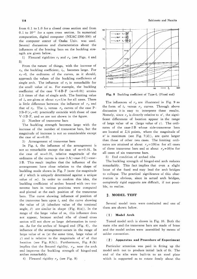
4) Flexural rigidity ry (see Fig. 9)
The innuences of ry are illustrated in Fig.9as
the form of λr versus ry curves. Through above
discussion it is easy to interprete these results.
Namely, since ry is directly relative to α', the signi-
ficant differences of location appear in the range
of large value of m (large value of γ). The ordi-
nates of the case-3 B whose side-transverse barsare located at L/4 points, where the magnitude ofα' is maximum (see Fig.7(d)), are quite larger
than those of other two cases. The limiting ordi-nates are attained at about ry=100/m for all cases of three transverse bars and at about ry=10/m for all cases of six transverse bars.
5) End condition of arched ribs
The buckling strength of hinged-end arch reduces remarkably. This fact implies that even a slight loose of the fixed end may lead the arch bridges to collapse. The practical significance of this obse-rvation is obvious, since in actual arch bridges, completely rigid supports are difficult, if not possi-ble, to realize.
3. MODEL TEST
Several model tests were conducted and one of them are shown below.
( 1 ) Model Arch
Tested model arch is shown in Fig. 10. Both the-main ribs and the transverse bars are made of brass and the model arches were assembled by means of solder connection.
( 2 ) Apparatus and Procedure of Experiment
Particular attention was paid in fitting up the model arch not to produce initial lack of fit. The end of the ribs were built-in to an steel plate which is supported as to rotate freely about the
Fig. 9 Buckling coefficient of Type-L (Fixed end)

Out-of-Plane Buckling of Solid Rib Arches Braced with Transverse Bars 115
axis perpendicular to the arch plane.
In order to prevent slipping and to
give full play to an arch action, the
ends of the arches were carefully fixed
against horizontal displacements. Since
it is difficult to realize a distributed
radial load, group of vertical concen-
trated loads was applied in place of it. The loading
devices are shown in Photo 1. The piano wire were
a) Geometrical contlqulatmo of model arch
b) Cross-sectional dimensions
used as to follow the displacement outward the arch plane without restraint, but the excentricity of loading was inevitable because of the cross-secti-onal shape of model arch. The loading rod was
pulled downward by a hydraulic jack. Model arch was loaded gardually and carefully not to produce disturbance.
( 3 ) Results and Consideration
The ultimate load was estimated as P= 1.40 t from
the asymptote of the load-deformation curves. The
model arch in critical equilibrium state at P=1.35 t
is shown in Photo 2. Test results are illustrated in
Fig. 11. These curves show the effects of initial
imperfection in lower range of loading, but to
avoid them was, actually, difficult. Both the buc-
kling load obtained from the theoretical analysis and
model test are shown in Table 2. The experimental
value shows about 90%-coincidence with the the-
oretical one.
4. CONCLUSIONS
The following conclusions will be drawn within the scope of the given assumptions and idealizati-ons :
1) Transfer matrix method was employed effec-tively in obtaining the eigenvalue of the differential equation governing the buckling of complicated structures which consist of main systems and branch systems.
2) Results of numerical computation about seve-ral arches are illustrated as the curves of buckling coefficient versus flexural rigidity of the transverse bars.
3) The arrangement of the transverse bars are in close relation to the shape of buckling mode of corresponding single arch. To arrange the transve-rse bars of large flexural rigidity at the location where corresponding large deformations of the arched ribs occurs is effective from the view point of lateral stability. That may be, in other words, to increase the total strain energy stored in the transverse bars during the buckling deformation.
4) In order to interprete the relation between the cross-sectional quantities of the arched rib andthe effects of transverse bars, the ratio, γ, of the
maximum value of the torsional angle, βmax, to
that of lateral deflection angle, αmax' are qulte
Fig. 10 Model arch
Photo 1 Loading devices Photo 2 Critical equili-
brium state at
P=1.35 ton
Fig. 11 Load vs. deformation curves
Table 2 Theoretical and experimental buckling load

116 Sakimoto and Namita
important.
5) The location of the transverse bars are more
important than the number of them.
6) In order to increase the buckling strength of
the arch bridges as treated in this paper, to cons-
train the out-of-plane flexure of arched rib is much
more effective than to constrain the torsional defor-
mation of arched rib. In other words, lateral braci-
ngs which resist to the out-of-plane flexure may be
more effective than the transverse bars of Vierendeel
type.
7) A slight loose of the fixed end about the
out-of-plane rotation may lose the buckling strength
of the arch bridges practically.
ACKNOWLEDGMENTS
The authors are greatly indebted to Professor
Dr. S. Komatsu for his important advice and enco-
uragement. Furthermore, acknowledgment due to
Mr. M. Taga for his co-operation in the experime-
nts and to Mr. Y. Iwahana for part of numerical
computations. This study was performed under
Financial Support of Ministry of Education.
REFERENCES
1) Namita, Y. : Die Theorie II. Ordnung von Kru-mmen Staben und ihre Anwendung auf das Kipp-
Problem des Bogentragers, Trans. of J.S.C.E., No. 155, 1968 (in German).
2) Kuranishi, S. : Torsional Buckling Strength of Solid Rib Arch Bridge, Trans. of J.S.C.E., No. 75, 1961
(in Japanese). 3) Ostlund, L. : Lateral Stability of Bridge Arches bra-
ced with Transverse Bars, Trans. of the Royal Institute of Technology, Stockholm, Sweden, No. 84, 1954.
4) Wastlund, G. : Stability Problems of Compressed Steel Members and Arch Bridges, Proc. of A.S.C. E., Vol. 86, St 6, June, 1960.
5) Kuranishi, S. : Analysis of Arch Bridge under certain Lateral Forces, Trans. of J.S.C.E., No. 73, 1961 (in
Japanese) . 6) Fukasawa, Y. : Buckling of Circular Arches by
Lateral Flexure and Torsion under Axial Thrust, Trans. of J.S.C.E., No. 96, 1963 (in Japanese).
7) Pestel, E.C. and Leckie, F.A. : Matrix Method in Elastomechanics, McGraw-Hill, 1963.
8) Okumura, A. : On a Method of Analysis for Vibr-ation and Stability Problems of Linear Mechanical Systems or Structures, Memories of the School of Science and Engineering, Waseda Univ., No. 21, 1957.
9) Shibata, M. : An Analysis for Vibration of Structu-res by Transfer Matrix Method, Journal of J.S.S. C., Vol. 3, No. 24, 1967 and Vol. 4, No. 27, 1968
(in Japanese).10) Margurre, K. : Vibration and Stability Problems of
Beams Treated by Matrices, Journal of Mathe. and Physics, Vol. 35-1, 1956.
(Recived Nov. 14, 1970)