our logo chapter highway design subject · revision of manual style sheet & template hd-xxx...
TRANSCRIPT

HD-XXX
01/08 Page 1 of 27
(YOUR LOGO)
Chapter INTERSECTION—At Grade Intersections
Subject
Modern Roundabouts
HIGHWAY
DESIGN
INTRODUCTION The modern roundabout is an at-grade intersection design with a
generally circular shape that uses yield control on entry Studies throughout the US and Kentucky demonstrate that when a roundabout is designed properly, significant safety, operational, and cost benefits can be achieved over other types of intersection control. This research also substantiates that when improperly designed or implemented, roundabouts can experience higher crash rates, high operational delays, and increased costs. The Kentucky Transportation Cabinet recognizes that the roundabout can be a viable intersection alternative when located appropriately and designed properly for operational conditions. This document provides guidance for the planning and design of roundabouts in Kentucky.
WARRANT ANALYSIS A modern roundabout is an alternative form of intersection control to
traffic signals and multi-way stop control intersections. Therefore, roundabouts may be considered only when these intersection control types are warranted. The investigation of the need for a roundabout shall include an analysis of factors related to the existing operation and safety at the study location and the potential to improve these conditions; and the applicable factors contained in the following traffic signal warrants and multi-way stop applications guidance contained in the Manual on Uniform on Traffic Control Devices summarized below
Section 1B.07 Multi-way Stop Applications.
♦ (C) Minimum Volumes.
Section 4C.01 Studies and Factors for Justifying Traffic Control
Signals ♦ Section 4C.02 Warrant 1, Eight-Hour Vehicular Volume ♦ Section 4C.08 Warrant 7, Crash Experience,
• Sub-section (B) should be interpreted to read “Five or more
reported crashes, of types susceptible to correction by a modern roundabout , have occurred within a 12-month period, each crash involving personal injury or property damage

REVISION OF MANUAL Style Sheet & Template HD-XXX
07/10 Page 2 of 27
apparently exceeding the applicable requirements for a reportable crash;”
♦ Section 4C.09 Warrant 8, Roadway Network All warrants shall be based on opening year traffic volumes, with the exception of the provisions for Warrant 8. If eight-hour volume data is not available for opening year traffic projections to evaluate the warrants, the Division of Planning or Division of Traffic Operations should be contacted for guidance on estimating the 8th highest hour from Average Daily Traffic or Design Hour estimates.
OPERATIONAL ANALYSIS Operational analysis of roundabouts shall include the evaluation of the
following measures of effectiveness:
volume to capacity (V/C) ratio of each approach lane
delay by lane, approach, and intersection
lane group queue estimates Volume to Capacity Ratio (V/C). The volume to capacity ratio shall be determined for each approach lane at the roundabout. Approach lane capacity estimates and volume to capacity ratios shall be used to determine the feasibility of the roundabout to meet the anticipated design year demand. All approach lanes to the intersection shall have a V/C ≤ 0.85 for the design year analysis. The following guidance is provided to assist in the calculation of the volume to capacity ratio with adjustment for heavy vehicles, roundabout geometry and pedestrian interference. Intersection volumes should be adjusted by peak hour factor (PHF) and a heavy vehicle adjustment factor (fHV), as shown in Equation 1 below. Equation 1: Passenger car equivalent flow rate calculation vp = V / (PHF × fHV) where: vp = passenger car equivalent flow rate (pcu/h)
PHF = Peak Hour Factor fHV = Heavy vehicle adjustment factor (1/(1+PT)), PT = percent heavy vehicles
Equations provided in NCHRP Report 572 “Roundabouts in the United States,” and shown below in Equations 2 and 3, shall be used to determine the capacity and V/C of each approach. Micro-simulation Simulation shall not be used to provide capacity estimates of roundabouts.

REVISION OF MANUAL Style Sheet & Template HD-XXX
07/10 Page 3 of 27
Equation 2: Single Lane Circulating Flow Capacity Equation c = 1130(e (-0.0010 × vc
))
where: c = entry capacity (passenger car units [pcu]/h) vc = conflicting flow (pcu/h) Equation 3: Multiple Lane Circulating Flow Capacity Equation
c = 1130(e (-0.0007 × vc
))
where: c = entry capacity (passenger car units [pcu]/h) vc = conflicting flow (pcu/h) Geometric and Pedestrian Effect of Capacity. Pedestrian conflicts and geometric conditions should also be used to adjust the lane capacity by applying the reduction factors identified in Figure 1 and Table 1, below. Adjusted lane capacity shall be determined using Equation 4. Figure 1: Capacity Reduction Factor for Pedestrian Conflicts (Mp)

REVISION OF MANUAL Style Sheet & Template HD-XXX
07/10 Page 4 of 27
Table 1: Capacity Reduction Factor for Short Entry Lanes (Ms) Number of Vehicle Spaces in Short Lane
Capacity Reduction Factor (Ms)
0 0.000 1 0.414 2 0.588 4 0.742 6 0.812 8 0.852 10 0.878 >10 1.000
Equation 4: Adjusted Entry Lane Capacity c’ = c(Mp)(Ms) where: c' = adjusted lane capacity c = unadjusted lane capacity (based on equations 1 or 2) Mp = Pedestrian Conflict Capacity Reduction Factor (Figure 1) Ms = Short Lane Capacity Reduction Factor (Table 1) The volume to capacity ratio (V/C) shall be calculated as shown in Equation 5. Equation 5: Volume to Capacity Ratio (V/C) v/c = vp/c’ where: c' = adjusted lane capacity vp = passenger car equivalent flow rate (pcu/h) Operational Delay. Delay estimates for each approach lane should be used in comparative analysis with other intersection alternatives. Approach delay should be calculated using the NCHRP 572 equation provided below (Equation 6). Micro-simulation models may be used to provide delay estimates at roundabouts and are appropriate where traffic patterns are impacted by nearby traffic control devices and do not follow a random arrival pattern assumed by the NCHRP 572 equations. Simulation software packages should be chosen by the project team based on project needs.

REVISION OF MANUAL Style Sheet & Template HD-XXX
07/10 Page 5 of 27
Equation 6: Approach Delay Calculation
where: d' = average control delay (s/veh) c = capacity of subject lane (veh/h)
T = Time period (h: T = 1 for 1 hour analysis; T = 0.25 for 15 min analysis v = flow in subject lane (veh/h)
Queue Estimates. Queue estimates for each approach lane should be used to determine the feasibility of the intersection alternative function within the site constraints, considering adjacent intersections and access points. Additionally, queue estimates should be used to size necessary flared or auxiliary approach lanes or be used in comparative analysis with other intersection alternatives. Unsignalized analysis procedures in the Highway Capacity Manual (HCM) should be used to determine the 95th percentile queue for each approach lane at isolated intersections. These procedures are summarized in Equation 7, below. Micro-simulation models may be used to provide queues estimates at roundabouts and are appropriate where traffic patterns are impacted by nearby traffic control devices and do not follow a random arrival pattern assumed by the HCM equations.
Equation 7: 95th Percentile Queue Calculation
where: Q95 = 95th percentile queue (veh) c = capacity of subject lane (veh/h)
T = Time period (h: T = 1 for 1 hour analysis; T = 0.25 for 15 min analysis v = flow in subject lane (veh/h)

REVISION OF MANUAL Style Sheet & Template HD-XXX
07/10 Page 6 of 27
BASIC DESIGN ELEMENTS Figure 2 shows the basic design elements of a modern roundabout. Each
of these elements is discussed in further detail in the following sections.
Figure 2: Basic Design Elements
Design Vehicle. Roundabouts should be designed to accommodate the largest vehicle that can reasonably be anticipated. Because roundabouts are intentionally designed to slow traffic, narrow curb-to-curb widths and tight turning radii are used. Large trucks and buses dictate many of the roundabout’s dimensions. Therefore, it is necessary to determine the design vehicle at the start of the design and investigation process.
The design vehicle should be determined by the individual context of the project, considering the type of intersecting roadways, adjacent and nearby land uses and the types and volume of vehicles using the intersection. Table 2 below summarizes a recommended design vehicle based on the roadway classification.

REVISION OF MANUAL Style Sheet & Template HD-XXX
07/10 Page 7 of 27
Table 2: Recommended design vehicle by route classification
Route Classification Design Vehicle
State Routes Principal Arterial WB‐65 Designated Truck Route
WB‐65
Other State Routes WB‐50
Non‐State Routes Major Streets WB‐50
Other Bus
Single Unit Fire truck
Design vehicles of special size or characteristics should also be taken into consideration when dimensioning and laying out the geometric features of a roundabout. Special care should also be taken to ensure that existing or anticipated bus routes are accommodated. Designers should verify that local emergency agencies have been made aware of the plans to construct a roundabout in their area. Often the design of roundabouts in these areas require close cooperation with local emergency agencies, as well as an understanding of the turning and operating characteristics of emergency vehicles using the roundabout.
Where there is the possibility of use by larger vehicles, such as mobile homes, that may not be accommodated within the roadway or truck apron, care should be taken to place signing, lighting and landscaping outside of the turning paths of such vehicles.
Circulatory Roadway Width. The required width of the circulatory roadway is determined from the number of entry lanes and the turning paths of the design vehicle(s). Single Lane Roundabouts. At single-lane roundabouts, the circulatory roadway should accommodate a city transit bus, school bus, or single unit truck and should remain constant throughout the roundabout. Turning templates shall be used to determine the swept path of these vehicles through each of the turning movements (Figure 3). For single lane roundabouts, the circulatory roadway width shall not exceed 16 ft to discourage drivers from traveling side-by-side. When this width is insufficient to accommodate bus or single unit truck turning paths the inscribed diameter should be reviewed. When this width is insufficient to accommodate the design vehicle (e.g., WB-50 or WB-65) a truck apron should be used.
REVISION OF MANUAL Style Sheet & Template HD-XXX
07/10 Page 8 of 27
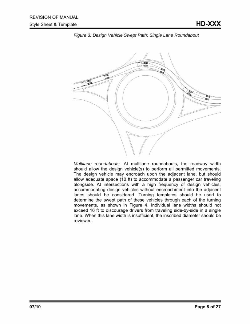
Figure 3: Design Vehicle Swept Path; Single Lane Roundabout
Multilane roundabouts. At multilane roundabouts, the roadway width should allow the design vehicle(s) to perform all permitted movements. The design vehicle may encroach upon the adjacent lane, but should allow adequate space (10 ft) to accommodate a passenger car traveling alongside. At intersections with a high frequency of design vehicles, accommodating design vehicles without encroachment into the adjacent lanes should be considered. Turning templates should be used to determine the swept path of these vehicles through each of the turning movements, as shown in Figure 4. Individual lane widths should not exceed 16 ft to discourage drivers from traveling side-by-side in a single lane. When this lane width is insufficient, the inscribed diameter should be reviewed.

REVISION OF MANUAL Style Sheet & Template HD-XXX
07/10 Page 9 of 27
Figure 4: Design Vehicle Swept Path; Multi-lane Roundabout
The outside of the circulatory roadway shall utilize Standard Curb as shown in Standard Drawing No. RPM-100-09.
Inscribed Circle Diameter. The inscribed circle diameter consists of the circulating roadway width, truck apron, and central island. The inscribed diameter will primarily be controlled by the turning radius of the design vehicle. In some instances, the design vehicle may be prohibited on local side streets and thus only the permitted movements should be accommodated in the design. For multi-lane roundabouts, the design vehicle should be able to perform all permitted maneuvers with the encroachments discussed above from the outside lane. Vehicles using the interior lane may use the truck apron.
Tables 3 and 4 define the minimum inscribed circle diameter based upon design vehicle and turning movements. These values are provided for preliminary layout guidance only; the final size and layout of the roundabout shall be verified using turning templates.

REVISION OF MANUAL Style Sheet & Template HD-XXX
07/10 Page 10 of 27
Table 3: Single Lane Roundabout Inscribed Circle Diameter
Movement Minimum Inscribed Diameter (ft) Bus / Single Unit Truck
WB‐50 WB‐65
Through 75 85 90 Left Turn 90 95 120
U‐Turn 90 100 135
Table 4: Double Lane Roundabout Inscribed Circle Diameter
Movement
Minimum Inscribed Diameter (ft)
Bus/ Single Unit Truck WB‐50 WB‐65
Through 110 125 150 Left Turn 125 150 200 U‐Turn 125 150 200 Circular roundabouts are preferred, but ovals and asymmetrical designs may be used when circular designs are not feasible due to site constraints.
Truck Apron. The truck apron is a raised traversable area on the central island. Truck aprons are used to accommodate over tracking turning paths of the design vehicle on the inside circulatory lane, while maintaining sufficient deflection and lane widths for smaller vehicles. The truck apron shall be mountable by the trailers of the design vehicle, but designed so that mounting by cars, SUV's and light trucks is discouraged. When used, a truck apron should be more than two feet and less than 14 feet wide. If the proposed apron is outside of these parameters the inscribed circle diameter of the roundabout should be reevaluated. The material of the truck apron should contrast the circulatory roadway to distinguish between the two.
Truck aprons shall use an island curb as shown in Standard Drawing No. RPM-100-09.
Central Island. The central island of a roundabout is the area surrounded by the circulating roadway and truck apron. The central island should be a raised non-traversable island. The size of the central island is determined by the remaining space available not used by the circulatory roadway or truck apron.
REVISION OF MANUAL Style Sheet & Template HD-XXX
07/10 Page 11 of 27
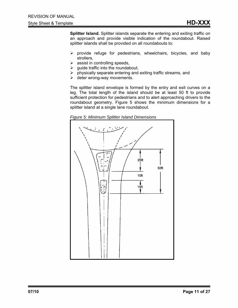
Splitter Island. Splitter islands separate the entering and exiting traffic on an approach and provide visible indication of the roundabout. Raised splitter islands shall be provided on all roundabouts to:
provide refuge for pedestrians, wheelchairs, bicycles, and baby strollers,
assist in controlling speeds, guide traffic into the roundabout, physically separate entering and exiting traffic streams, and deter wrong-way movements.
The splitter island envelope is formed by the entry and exit curves on a leg. The total length of the island should be at least 50 ft to provide sufficient protection for pedestrians and to alert approaching drivers to the roundabout geometry. Figure 5 shows the minimum dimensions for a splitter island at a single lane roundabout. Figure 5: Minimum Splitter Island Dimensions

REVISION OF MANUAL Style Sheet & Template HD-XXX
07/10 Page 12 of 27
Standard AASHTO guidelines for island design should be followed for the splitter island. This includes using larger nose radii at approach corners to maximize island visibility and offsetting curb lines at the approach ends to create a funneling effect. Figure 6 shows minimum splitter island nose radii and offset dimensions from the entry and exit traveled ways. Figure 6: Splitter Island Offset Dimensions
In high speed areas (>45 mph) the splitter island should be equal to the stopping distance of the approach, and shall be a minimum of 200 ft long, to give early warning to drivers that they are approaching an intersection and must slow down. The splitter island and its approach pavement markings should extend back to the point where a driver would be expected to start slowing down. Outside curbs should be placed on the right-hand side for at least half of the length of the splitter island. Outside curb shall be a standard curb as shown in Standard Drawing No. RPM-100-09. Splitter islands shall use a island curb as shown in Standard Drawing No. RPM-100-09.
REVISION OF MANUAL Style Sheet & Template HD-XXX
07/10 Page 13 of 27
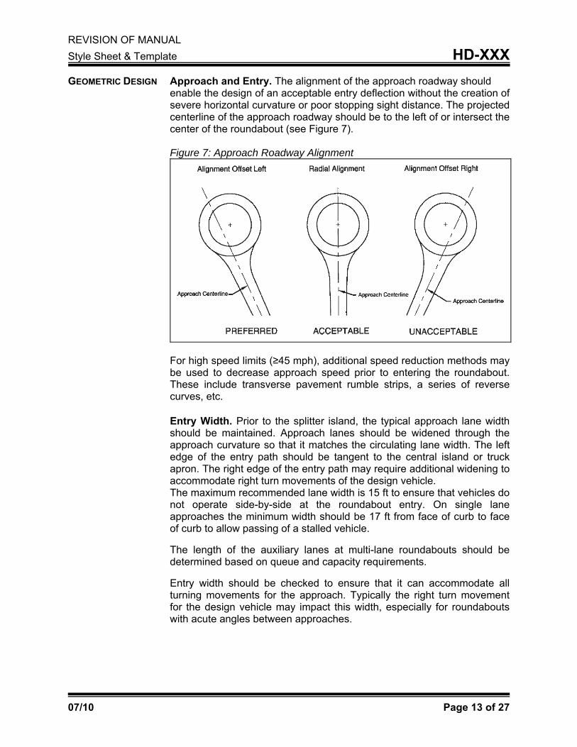
GEOMETRIC DESIGN Approach and Entry. The alignment of the approach roadway should enable the design of an acceptable entry deflection without the creation of severe horizontal curvature or poor stopping sight distance. The projected centerline of the approach roadway should be to the left of or intersect the center of the roundabout (see Figure 7). Figure 7: Approach Roadway Alignment
For high speed limits (≥45 mph), additional speed reduction methods may be used to decrease approach speed prior to entering the roundabout. These include transverse pavement rumble strips, a series of reverse curves, etc. Entry Width. Prior to the splitter island, the typical approach lane width should be maintained. Approach lanes should be widened through the approach curvature so that it matches the circulating lane width. The left edge of the entry path should be tangent to the central island or truck apron. The right edge of the entry path may require additional widening to accommodate right turn movements of the design vehicle. The maximum recommended lane width is 15 ft to ensure that vehicles do not operate side-by-side at the roundabout entry. On single lane approaches the minimum width should be 17 ft from face of curb to face of curb to allow passing of a stalled vehicle.
The length of the auxiliary lanes at multi-lane roundabouts should be determined based on queue and capacity requirements.
Entry width should be checked to ensure that it can accommodate all turning movements for the approach. Typically the right turn movement for the design vehicle may impact this width, especially for roundabouts with acute angles between approaches.

REVISION OF MANUAL Style Sheet & Template HD-XXX
07/10 Page 14 of 27
Figure 8: Outside Truck Apron
Entry Angle. The entry angle, Ø (Phi), represents the conflicting angle between entering and circulating streams of traffic. Entry angle is a critical factor in both capacity and safety operations at roundabouts. Large entry angles can create a decrease in capacity and increase the likelihood of crashes into the central island; small entry angles increase capacity but increase the likelihood of entry crashes with circulating traffic. The entry angle should be between 20-40 degrees.
If acceptable entry angles cannot be achieved, alternative inscribed diameters should be considered as well as modified alignments of each approach to change the angle between approach legs. Under special constraints the entry angle may be modified to achieve the desired design result. Entry radii (R1) values discussed in the next section should control the entry angle in these instances. There are three methods or design conditions in which Ø (Phi) can be measured. They are: Condition 1. The distance between the left sides of an entry and the next exit are less than 100 ft. In Condition 1, 2Ø (Phi) is the angle formed by the intersection of the tangent line (A-B) projected from the midpoint of the entry width with a tangent line (C-D) drawn along the middle of the adjacent exit. The acute angle is denoted as 2Ø in which the actual angle must be divided by two to obtain Ø. (See Figure 9).
REVISION OF MANUAL Style Sheet & Template HD-XXX
07/10 Page 15 of 27
Figure 9: Entry Angle Condition 1
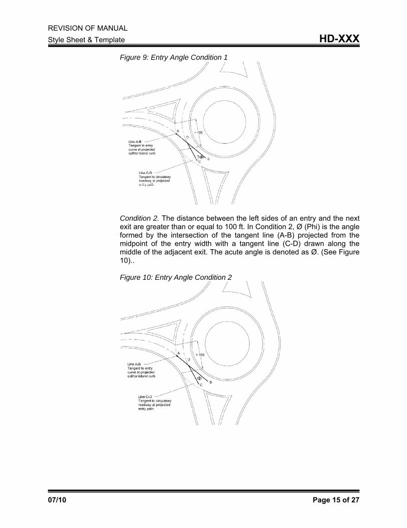
Condition 2. The distance between the left sides of an entry and the next exit are greater than or equal to 100 ft. In Condition 2, Ø (Phi) is the angle formed by the intersection of the tangent line (A-B) projected from the midpoint of the entry width with a tangent line (C-D) drawn along the middle of the adjacent exit. The acute angle is denoted as Ø. (See Figure 10).. Figure 10: Entry Angle Condition 2

REVISION OF MANUAL Style Sheet & Template HD-XXX
07/10 Page 16 of 27
Condition 3. An adjacent exit does not exist or an exit located at such a distance or obtuse angle to render the circulatory roadway a dominating factor of an entry. Ø (Phi) is now the angle formed by the intersection of the tangent line (A-B) projected from the midpoint of the entry width with a tangent line (C-D) drawn along the middle of the circulatory roadway. Condition 3 is used at “T” intersections or where the adjacent entrance and exit lane(s) are far apart. (See Figure 11).
Figure 11: Entry Angle Condition 3
Entry Deflection. A primary design consideration influencing the safe operation of a roundabout is adequate deflection of the vehicle as it enters and progresses through the roundabout. Deflection is measured by identifying the fastest path of a single vehicle through the roundabout for a given movement. The fastest path is drawn assuming a vehicle starts at the left-hand edge of the approach lane, moves to the right side as it enters the roundabouts, cuts to the left side of the circulatory roadway, then moves back to the right side at the exit, and completes its move at the left-hand side of the departure lane. The centerline of the vehicle path is drawn using the following offset distances:
5 ft from concrete curbs, 5 ft from roadway centerline, and 3 ft from striped edge line or lane
Figures 12 and 13 demonstrate the fastest through vehicle paths at a single-lane roundabout and a double-lane roundabout, respectively. Figure 14 provides an example of an approach at which the right-turn path is more critical than the through movement.

REVISION OF MANUAL Style Sheet & Template HD-XXX
07/10 Page 17 of 27
Figure 12: Fastest path (through) at single lane roundabout
Figure 13: Fastest path (through) at Multi-lane roundabout
Figure 14: Fastest path (right turn) at roundabout

REVISION OF MANUAL Style Sheet & Template HD-XXX
07/10 Page 18 of 27
Deflection of the roundabout is determined from the entry path radius along the fastest path (i.e., as the vehicle curves to the right through entry geometry). The entry path radius is shown in Figure 15 and denoted as R1 or R5. Both the through and right turn fastest paths should be determined and drawn for all approaches.
Figure 15: Entry Path Radius
The maximum entry path radius for single lane roundabouts should be 225 feet and 275 feet for multi-lane roundabouts. The minimum entry path radius will be controlled by accommodation of the design vehicle. If an acceptable entry path radius cannot be achieved, larger inscribed diameters or larger central islands should be considered. The approach alignment may also be offset to the left of the roundabout center, the angle between legs of the roundabouts increased or a staggered alignment between the entry and exit provided. Note that these changes will impact the fastest paths of the other legs and impact other design criteria such as entry angle.
Exit Curves. Exit curves should be designed to minimize the likelihood of congestion and crashes at the exits. In order to achieve this result, exit speeds should be higher than or equal to the circulating speed. The exit curve should produce an exit path radius (R3 in Figure 16) greater than or equal to the circulating path radius (R2). This larger radius does not translate into a faster speed as the exit speed is controlled by the circulating speed plus acceleration to the exit crosswalk.

REVISIOStyle She
07/10
ON OF MANUeet & Templ
UAL ate
The exit croadway wbeginning
Figure 16:
Multi-Lancomplicateconflicts pthe effect likelihood The use ocirculatoryhowever, provided. considerat
curves alsowidth to the of the exit b
: Exit Path R
e Consided to desigresent with of path ov
of sideswipef designated
y roadway caproper alig
The follotions to mini
serve to texit lane w
beyond the s
Radius
derations. n than singmultiple traffverlap on ee crashes wd lane assignan significannment of thowing sectmize the ris
aper the exwidth. This tasplitter island
Multilane gle-lane roufic streams.
entry and eithin the circnments for tntly reduce ohe entry antions identk of path ove
xit lane fromaper should d.
roundabouundabouts d
The primaryexit which cculatory roadurning moveoccurrencesnd exit lanetify the rerlap.
HD-X
Page 19
m the circulextend from
uts are due to addity consideratcan increasedway (Figureements withis of path ovees must alsrequired de
XXX
of 27
lating m the
more tional ion is e the e 17). in the erlap; so be esign
REVISION OF MANUAL Style Sheet & Template HD-XXX
07/10 Page 20 of 27
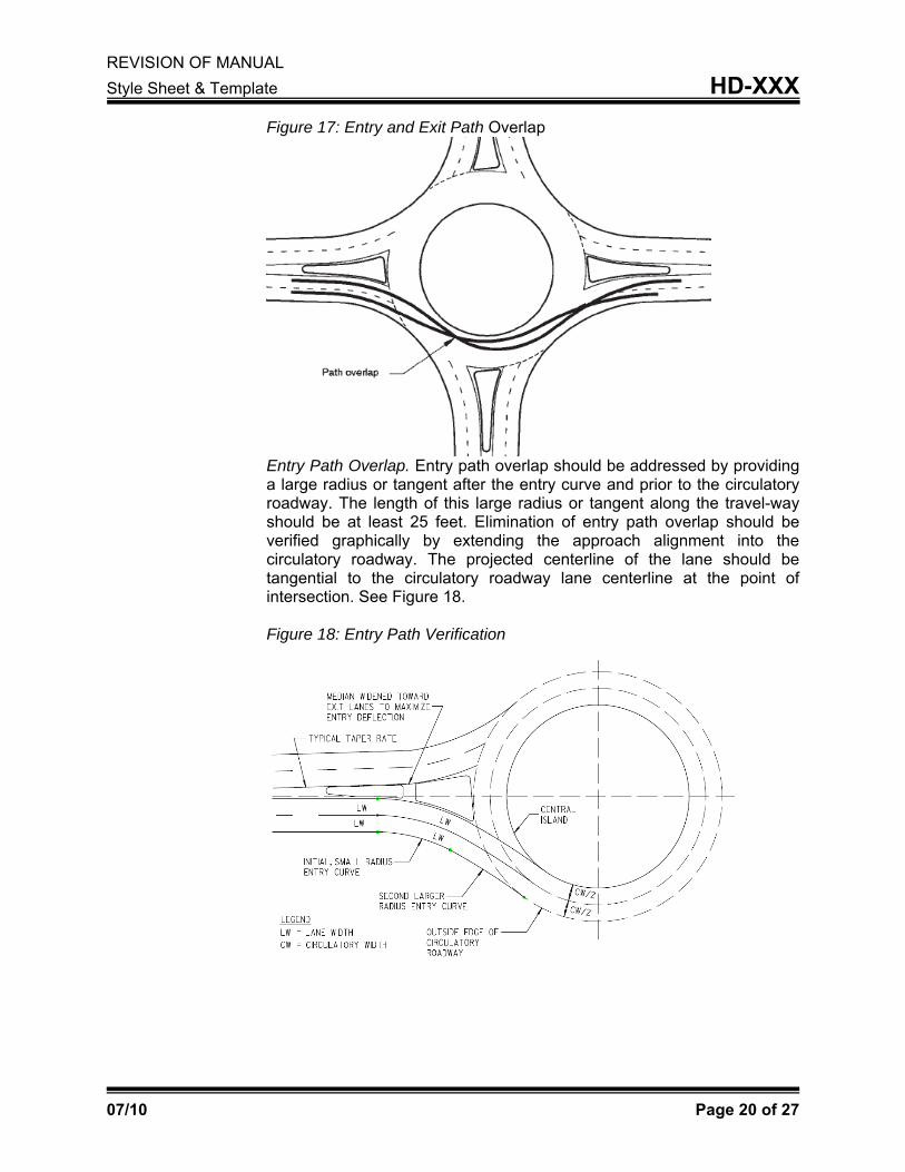
Figure 17: Entry and Exit Path Overlap
Entry Path Overlap. Entry path overlap should be addressed by providing a large radius or tangent after the entry curve and prior to the circulatory roadway. The length of this large radius or tangent along the travel-way should be at least 25 feet. Elimination of entry path overlap should be verified graphically by extending the approach alignment into the circulatory roadway. The projected centerline of the lane should be tangential to the circulatory roadway lane centerline at the point of intersection. See Figure 18. Figure 18: Entry Path Verification
REVISION OF MANUAL Style Sheet & Template HD-XXX
07/10 Page 21 of 27
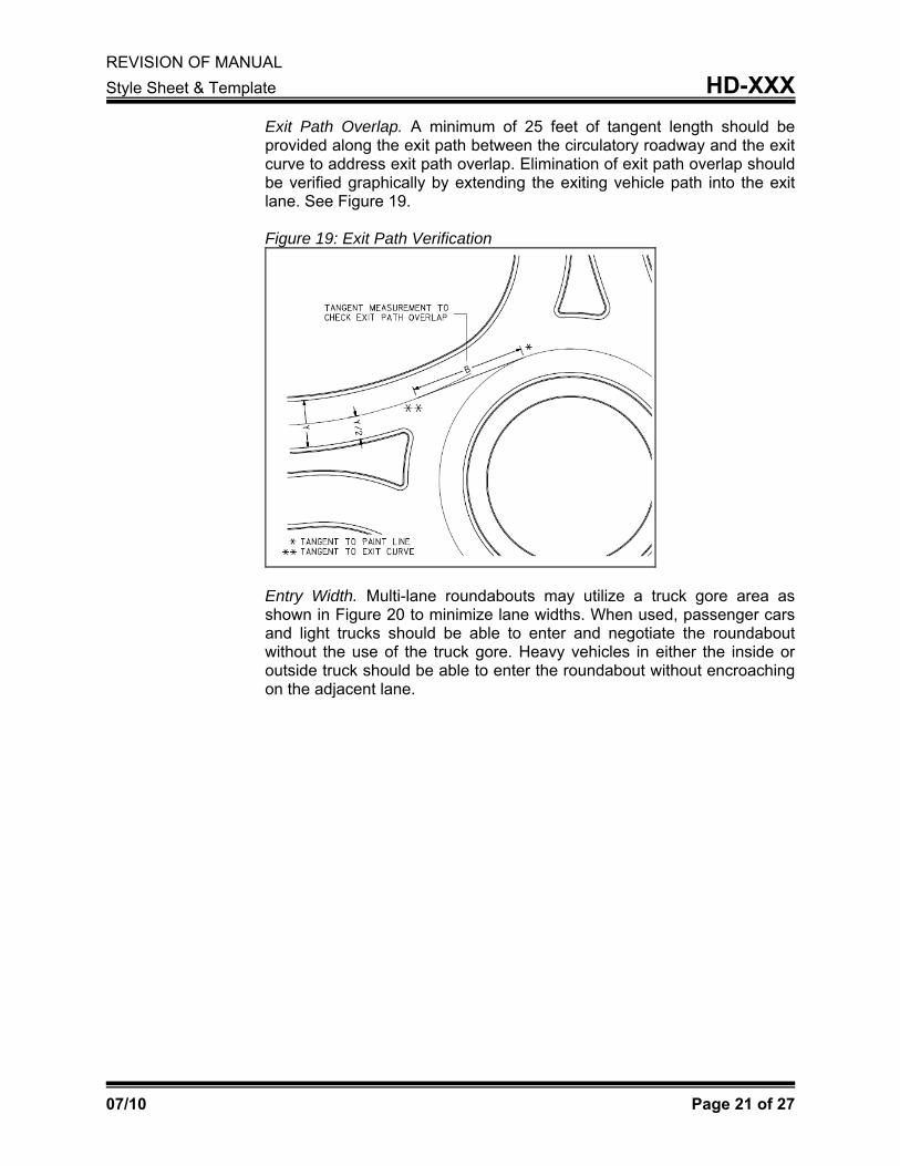
Exit Path Overlap. A minimum of 25 feet of tangent length should be provided along the exit path between the circulatory roadway and the exit curve to address exit path overlap. Elimination of exit path overlap should be verified graphically by extending the exiting vehicle path into the exit lane. See Figure 19. Figure 19: Exit Path Verification
Entry Width. Multi-lane roundabouts may utilize a truck gore area as shown in Figure 20 to minimize lane widths. When used, passenger cars and light trucks should be able to enter and negotiate the roundabout without the use of the truck gore. Heavy vehicles in either the inside or outside truck should be able to enter the roundabout without encroaching on the adjacent lane.

REVISION OF MANUAL Style Sheet & Template HD-XXX
07/10 Page 22 of 27
Figure 20: Truck Gore and Outside Truck Apron
SIGHT DISTANCE For a roundabout to operate satisfactorily, a driver must be able to enter the roundabout, move through the circulating traffic, and separate from the circulating stream in a safe and efficient manner. To accomplish this, a driver must be able to perceive the general layout and operation of the intersection in time to make the appropriate maneuvers.
Stopping Sight Distance. Stopping sight distance is the distance along a roadway required for a driver to perceive and react to an object in the roadway and to brake to a complete stop before reaching that object. Table 5 gives recommended stopping sight distances based on design speed. Table 5: Stopping Sight Distance by Design Speed (Exhibit 3-1 AASHTO Green Book)
Design Speed (mph) Stopping Sight Distance (ft)
15 80 20 115 25 155 30 200 35 250 40 305 45 360 50 425 55 495

REVISION OF MANUAL Style Sheet & Template HD-XXX
07/10 Page 23 of 27
Sight triangles should be used to measure stopping sight distance. Stopping sight distance shall be provided at every point within a roundabout and on each entering and exiting approach and should be explicitly checked at a minimum of the three locations identified below. Figures 21, 22 and 23 illustrate the following stopping sight distances for roundabouts.
Approach sight distance. Sight distance on the circulatory roadway Sight distance to crosswalk on the immediate downstream exit
Stopping sight distance on the approach shall use an assumed height of driver’s eye of 3.5 ft and an assumed height of object of 0.5 ft in order to provide visibility of the curb and geometry of the intersection. Sight distance on the circulatory roadway and sight distance to the crosswalk may use an object height of 2.0 ft in accordance with the fourth edition of the AASHTO Green Book. Anticipated operating speeds at each point in the roundabout should be used to determine stopping sight distance. Therefore, approach stopping sight distance should consider the free-flow or design speed of the roadway; sight distances within the roundabout should be based on fastest paths speeds, i.e., R1, R2 and R5. Operating speed based on roadway curvature is summarized in Table 6. Table 6: Operating Speed by Radius
Radius (ft) Entry/Exit Curve Operating Speed
(mph)
Circulatory Operating Speed
(mph) 75 16 14 100 18 16 125 20 18 150 22 20 175 24 22 200 26 23 225 27 25 250 29 26

REVISION OF MANUAL Style Sheet & Template HD-XXX
07/10 Page 24 of 27
Figure 21: Approach Sight Distance
Figure 22: Sight Distance on the Circulatory Roadway
REVISION OF MANUAL Style Sheet & Template HD-XXX
07/10 Page 25 of 27
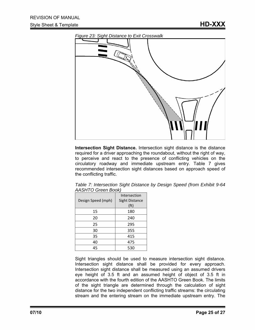
Figure 23: Sight Distance to Exit Crosswalk
Intersection Sight Distance. Intersection sight distance is the distance required for a driver approaching the roundabout, without the right of way, to perceive and react to the presence of conflicting vehicles on the circulatory roadway and immediate upstream entry. Table 7 gives recommended intersection sight distances based on approach speed of the conflicting traffic. Table 7: Intersection Sight Distance by Design Speed (from Exhibit 9-64 AASHTO Green Book)
Design Speed (mph) Intersection Sight Distance
(ft)
15 180 20 240 25 295 30 355 35 415 40 475 45 530
Sight triangles should be used to measure intersection sight distance. Intersection sight distance shall be provided for every approach. Intersection sight distance shall be measured using an assumed drivers eye height of 3.5 ft and an assumed height of object of 3.5 ft in accordance with the fourth edition of the AASHTO Green Book. The limits of the sight triangle are determined through the calculation of sight distance for the two independent conflicting traffic streams: the circulating stream and the entering stream on the immediate upstream entry. The

REVISION OF MANUAL Style Sheet & Template HD-XXX
07/10 Page 26 of 27
sight distance required for each stream is measured along the curved vehicle path, not as a straight line. Figure 24 presents a diagram showing the method for determining intersection sight distance. Figure 24: Intersection Sight Distance
SIGNING, PAVEMENT MARKINGS AND LIGHTING Lighting. Intersection control involving a roundabout shall be a
warranting condition for intersection lighting. When a roundabout is determined to be the preferred intersection control alternative, the Division of Traffic Operation shall be contacted to secure approval for the lighting system. At that time, the Division of Traffic Operations shall determine whether lighting plans will be developed internally or by a consultant. Lighting design should be developed in accordance with AASHTO Roadway Lighting Design Guide.
Contrary to typical intersection lighting, the Cabinet shall be responsible for the installation costs associated with the lighting of roundabouts within city limits. However, cities should be responsible for the maintenance and utility costs associated with these installations. As a result, agreements should be developed between the Cabinet and the city to address maintenance responsibilities for these systems. Signing and Markings. Signing and marking plans shall be developed in conformance with the Manual on Uniform Traffic Control Devices. These plans should be routed through the Division of Traffic Operations for review.

REVISION OF MANUAL Style Sheet & Template HD-XXX
07/10 Page 27 of 27
PEDESTRIAN AND BICYCLE ACCOMMODATIONS Pedestrian accommodations, in the form of crosswalks and ramps on the
splitter island, should be provided when adjacent pedestrian facilities are present or planned as part of the proposed project. All splitter islands should provide adequate width to allow retrofit of pedestrian facilities in the future. Bicycle accommodations, in the form of bike ramps connecting the roadway to sidewalks/multi-use paths should be provided when both on-street bike lanes and pedestrian accommodations are provided or planned.
ROUNDABOUT REVIEW AND APPROVAL Conceptual Design Approval. In order for a roundabout to be identified
as a preferred alternative, a concept report shall be submitted to, and approved by, the Division of Highway Design. This submittal should occur prior to public involvement activities and no later than the preliminary line and grade meeting. The concept report shall include at a minimum:
Operational analysis and determination of lane configuration Identification of design vehicle(s) Preliminary layout including identification of inscribed circle diameter
(see Tables 3 & 4) Final Design Approval. The following information shall be submitted for approval as an appendix to the Design Executive Summary.
Design vehicle turning paths Fastest path determination Entry Angle Sight Distance Analysis
This information should be submitted in graphical format. Traffic Operations Approval. Lighting, Signing and Pavement Markings shall be presented at the Joint Inspection Meeting for approval by the Division of Traffic Operations.