our first words to the owner/operator - bombardier ... first words to the owner/operator this...
TRANSCRIPT


Our First Words to the Owner/OperatorThis Operator’s Guide is an essential part of your Johnson outboard. It contains pertinent informationwhich, if followed, will provide you with a thorough understanding needed for proper operation, mainte-nance, care and above all safety!The safety section of this Guide comes first because it is our first priority and it should be yours too. It isstrongly recommended that you read this Guide from front cover to rear cover. Following this recommen-dation will assure the completeness of the information that is essential to your safety, the safety of anypassengers and other boaters. An Operator’s Readiness Test has been prepared on the last page of thisGuide.Be safe! All passengers should be familiar with the proper operation of your boat and Johnson outboard.Be certain they fully understand and respect the controls and operation. Each operator is responsible forthe safety of all passengers and other boaters. Please make safety your first priority and complete a boat-ing safety course through your local Coast Guard, Power Squadron, Red Cross or State Boating LawAgency.The pleasures of owning and operating a Johnson outboard can be significant. We strongly believe therewards for following our recommendations will be worthwhile. Remember that YOU are the key to safety.Good safety practices not only protect you but also protect the people around you.Having fun is what it’s all about and, with your cooperation, the pertinent information in this Guide can en-sure a safe and enjoyable experience.Enjoy the great outdoors on the water...
The following trademarks are the property of Bombardier Recreational Products Inc. or its affiliates:
WARNINGBe careful! Human error is caused by many factors: carelessness, fatigue, overload, preoccu-pation, unfamiliarity of operator with the product, drugs and alcohol to name a few. Damage toyour boat and outboard can be fixed in a short period of time, but injury or death has a lastingeffect.
For your safety and the safety of others, read this Guide from cover to cover and follow allsafety warnings and recommendations. Do not disregard any of the safety precautions andinstructions.
Anyone operating your boat should first read and understand this Guide before they operateyour boat and motor.
Evinrude® Johnson®
Evinrude®/Johnson® Genuine Parts 2+4® fuel conditioner
Evinrude®/Johnson® 4-Stroke outboard oil Hi-Vis™ gearcase lubricant
Evinrude®/Johnson® Ultra™ 4-Stroke synthetic blend oil Triple-Guard® grease
Evinrude®/Johnson® anti-corrosion spray Ultra-HPF™ gearcase lubricant
99011-91J03-BBD

© 2005 BRP US Inc. All rights reserved.TM, ® Trademarks and registered trademarks of Bombardier Recreational Products Inc. or its affiliates.
1
Contents
GENERAL INFORMATION ................................................................................................... 2SAFETY — THE RIGHT PLACE TO GET STARTED ................................................................................................ 2PRODUCT REFERENCES, ILLUSTRATIONS AND SPECIFICATIONS ................................................................... 4BRP LIMITED WARRANTY FOR 2006 JOHNSON 4-STROKE OUTBOARD ENGINES
SOLD IN THE UNITED STATES AND CANADA ................................................................................................ 5BRP LIMITED WARRANTY FOR 2006 JOHNSON 4-STROKE OUTBOARD ENGINES
SOLD OUTSIDE THE UNITED STATES AND CANADA ................................................................................... 8CALIFORNIA EMISSION CONTROL WARRANTY STATEMENT ............................................................................ 9FEATURES ............................................................................................................................................................... 12ENGINE SPECIFICATIONS ...................................................................................................................................... 14EMERGENCY STOP SWITCH .................................................................................................................................. 15
FUEL AND OIL ................................................................................................................... 16FUEL ......................................................................................................................................................................... 16OIL ............................................................................................................................................................................. 17ADDITIVES ................................................................................................................................................................ 17FUEL SYSTEM .......................................................................................................................................................... 17BREAK-IN (10 HOURS) ............................................................................................................................................ 18
ENGINE STARTING ........................................................................................................... 19BEFORE START-UP ................................................................................................................................................. 19ENGINE STOPPING ................................................................................................................................................. 21SHIFTING AND SPEED CONTROL ......................................................................................................................... 22EMERGENCY STARTING ........................................................................................................................................ 22
OPERATION ....................................................................................................................... 24MOTOR ANGLE ADJUSTMENT .............................................................................................................................. 24TILTING ..................................................................................................................................................................... 24SHALLOW-WATER DRIVE ...................................................................................................................................... 25MOORING ................................................................................................................................................................. 25FLUSHING ................................................................................................................................................................ 26ENGINE OVERHEATING .......................................................................................................................................... 27TRAILERING ............................................................................................................................................................. 28IMPACT DAMAGE .................................................................................................................................................... 28STORING .................................................................................................................................................................. 29CARRYING AND TRANSPORTING ......................................................................................................................... 29SPECIAL OPERATING CONDITIONS ..................................................................................................................... 30
MAINTENANCE .................................................................................................................. 31ENGINE EMISSIONS INFORMATION ...................................................................................................................... 3110-HOUR INSPECTION ............................................................................................................................................ 32OFF-SEASON STORAGE ........................................................................................................................................ 32PRE-SEASON SERVICE .......................................................................................................................................... 33CRANKCASE OIL ..................................................................................................................................................... 34ADJUSTMENTS ........................................................................................................................................................ 35LUBRICATION .......................................................................................................................................................... 36BREATHER AND FUEL LINE .................................................................................................................................. 38SPARK PLUGS ......................................................................................................................................................... 38PROPELLER ............................................................................................................................................................. 39ANTICORROSION ANODES .................................................................................................................................... 39TROUBLE CHECK CHART ...................................................................................................................................... 40ENGINE MAINTENANCE AND INSPECTION SCHEDULE ..................................................................................... 41
INSTALLATION .................................................................................................................. 43TRANSOM HEIGHT AND SHAFT LENGTH ............................................................................................................ 43INSTALLING THE ENGINE ...................................................................................................................................... 44

2 - General Information
GENERAL INFORMATION
SAFETY — THE RIGHT PLACE TO GET STARTED
This Operator’s Guide contains essential informa-tion to help prevent personal injury and damage toequipment. It will acquaint the operator and pas-sengers with the Evinrude/Johnson outboard andits controls, operation, maintenance and boatingsafety measures. Make sure all operators read, un-derstand and follow the contents. This Guideshould be kept in a waterproof bag with the productat all times during operation. If the product owner-ship is transferred, this Guide should be forwardedto the subsequent owners.This Operator’s Guide uses the following signalwords identifying important safety messages.These safety alert signal words mean:ATTENTION! BECOME ALERT!YOUR SAFETY IS INVOLVED!
IMPORTANT: Identifies information that will helpprevent damage to machinery and appears next toinformation that controls correct assembly and op-eration of the product.Although the mere reading of such informationdoes not eliminate the hazard, the understandingand application of the information will promote thecorrect use of your outboard engine.
A responsible, educated boater will fully appreciatethe pleasures of boating and will be a safe boater.Boating Safety Classes are conducted by the U.S.Coast Guard Auxiliary, the U.S. Power Squadronand some Red Cross Chapters. For informationabout classes, call toll free 1-800-336-BOAT. Foradditional information about boating safety and reg-ulations call: U.S. Coast Guard Boating Safety Hot-line 1-800-368-5647. Outside North Americaplease contact your Dealer or distributor for detailsabout boating safety.
SAFETY MEASURES — General
SAFETY MEASURES — Operation
DANGERIndicates an imminently hazardous situa-tion which, if not avoided, WILL result indeath or serious injury.
WARNINGIndicates a potentially hazardous situationwhich, if not avoided, CAN result in severeinjury or death.
CAUTIONIndicates a potentially hazardous situationwhich, if not avoided, MAY result in minor ormoderate personal injury or property dam-age. It also may be used to alert againstunsafe practices.
To fully appreciate the pleasures, enjoymentand excitement of boating there are some ba-sic rules that should be observed and fol-lowed by any boater. Some rules may be newto you and others may be common sense orobvious... irrespective, take them seriously!Failure to follow this safety information andsafe boating rules could result in injury to you,your passengers or other water users.
Become completely familiar with the controland operation of your boat and motor beforeembarking on your first trip or taking on a pas-senger(s). If you have not had the opportunityto do so with your Dealer, practice driving ina suitable area and feel the response of eachcontrol. Be familiar with all controls before ap-plying the throttle above idle speed. As theoperator, you are in control and responsiblefor safe operation.
Be sure at least one of your passengersknows how to handle your boat in case of anemergency.
All passengers should know the location ofemergency equipment and how to use it.
All safety equipment and personal flotationdevices must be in good condition and suit-able for your type of boat. Always comply withthe regulations that apply to your boat.
Contact with rotating propeller is likely to re-sult in serious injury or death. Do not allowanyone near a propeller, even when the en-gine is off. Propeller blades can be sharp andcan continue to turn even after the engine isshut off. Always shut off the engine whenboat is near people in the water.

General Information - 3
SAFETY MEASURES — Installation and Maintenance
Outboard Installation
Maintenance
Whenever running the engine, assure thereis proper ventilation to avoid carbon monox-ide (CO), which is odorless, colorless, andtasteless, and can lead to unconsciousness,brain damage, or death if inhaled in sufficientconcentrations. CO accumulation can occurwhile docked, anchored, or underway, and inmany confined areas such as the boat cabin,cockpit, swim platform, and heads. It can beworsened or caused by weather, mooringand operating conditions, and other boats.Avoid exhaust fumes from your engine or oth-er boats, provide proper ventilation, shut offyour engine when not needed, and be awareof the risk of backdrafting and conditions thatcreate CO accumulation. In high concentra-tions, CO can be fatal within minutes. Lowerconcentrations are just as lethal over long pe-riods of time.
Proceed with caution and at very low speedin shallow water. Grounding or abrupt stopsmay result in injury. Also be alert for debrisand objects in the water.
Be familiar with the waters you are operatingin. The gearcase of this outboard extends be-low the water surface and could potentiallycome in contact with underwater obstruc-tions. Contact with underwater obstructionsmay result in loss of control and personal in-jury.
Avoid standing up or shifting weight suddenlyin light weight boats.
Keep your passengers seated in seats. Theboat’s bow, gunwale, transom and seatbacks are not intended for use as seats.
Insist on the use of personal flotation devices,approved by the U.S. Coast Guard, by allpassengers when boating conditions arehazardous, and by children and nonswim-mers at all times.
Respect no wake zones, rights of other waterusers and the environment. As the "skipper"and owner of a boat you are responsible fordamage to other boats caused by the wake ofyour boat. Allow no one to throw refuse over-board.
Know the marine traffic laws and obey them.
Remember, gasoline fumes are flammableand explosive. Always adhere to the fuelingprocedure contained in this Operator’s Guideand those given to you by the fueling station.Always verify fuel level before use and duringthe ride. Apply the principle of 1/3 fuel to des-tination, 1/3 back and 1/3 reserve fuel supply.Do not carry spare fuel or flammable liquidsin any storage or engine compartments.
Do not operate your boat if you are under theinfluence of drugs or alcohol.
High performance boats have a high power-to-weight ratio. If you are not experienced inthe operation of a high performance boat, donot attempt to operate one at, or near, its topspeed until you have gained that experience.
For more information, see your Evinrude/Johnson Dealer for a copy of Introduction toHigh Performance Boating, P/N 335763.
The outboard must be correctly installed.Failure to correctly install the outboard couldresult in serious injury, death or propertydamage. We strongly recommend that yourDealer install your outboard to ensure properinstallation.
Do not overpower your boat by using an en-gine that exceeds the horsepower indicatedon the boat’s capacity plate. Overpoweringcould result in loss of control. If your boat hasno capacity plate, contact your Dealer or theboat’s manufacturer.
When replacement parts are required, useEvinrude®/Johnson® Genuine Parts or partswith equivalent characteristics, includingtype, strength and material. Using substan-dard parts could result in injury or productmalfunction.
Only perform service procedures which aredetailed in this Operator’s Guide. Attemptingto perform maintenance or repair on your out-board if you are not familiar with the correctservice and safety procedure could causepersonal injury or death. Further informationcan be obtained from your authorizedEvinrude/Johnson Dealer. In many instancesproper tools and training are required for cer-tain service or repair procedures.
Maintain your boat and engine in top condi-tion at all times. Adhere to the Engine Main-tenance and Inspection Schedule.
Operate your boat and outboard prudentlyand have fun. Do not forget that all personsmust assist other boaters in case of emer-gency.
Prevent injury from contact with rotating pro-peller; remove propeller before flushing orbefore performing any maintenance.

4 - General Information
PRODUCT REFERENCES, ILLUSTRATIONS AND SPECIFICATIONS
Bombardier Recreational Products (BRP) reservesthe right to make changes at any time, without no-tice, to features, specifications and model availabil-ity. The right is also reserved to change anyspecification or part at any time without incurringany obligation to update older models. The informa-tion in the Guide is based on the latest specifica-tions available at the time of publication.Photographs and illustrations used in this Guidemight not depict actual models or equipment butare intended as representative views for referenceonly. The continuing accuracy of this Guide cannotbe guaranteed.Certain features of systems discussed in this Guidemight not be found on all models in all marketing ar-eas.
Owner’s Identification
North America — At the time of purchase, yourDealer will complete your outboard registrationforms. Your portion provides proof of ownershipand date of purchase.
Outside North America — See your Dealer ordistributor for details.
Model and Serial NumbersThe model and serial numbers appear on a plate at-tached to the stern bracket or swivel bracket.Record your outboard’s:
Model Number _________________________________
Serial Number __________________________________
Purchase Date _________________________________
Ignition Key Number _____________________________
Stolen Outboards
North America — Report your outboard as stolento Customer and Dealer Support Services, 250 SeaHorse Drive, Waukegan, IL 60085, U.S.A. Give theoutboard’s model and serial numbers and enclosea copy of the police report.
Outside North America — Report the theft to theBombardier Recreational Products distributorwhere the outboard was registered.
Technical Literature
BRP offers technical literature specifically for youroutboard. A service manual, a parts catalog, or anextra Operator’s Guide can be purchased from yourselling Dealer. For the name and location of thenearest Evinrude/Johnson Dealer in the UnitedStates and Canada log on to www.evinrude.comor www.johnson.com.
Declaration of Conformity
BRP declares that the outboard to which this Oper-ator’s Manual applies conforms to the essential re-quirements outlined in CE Machinery Directive98-37-EC, as amended.
WARNINGWhen replacement parts are required, useEvinrude/Johnson Genuine Parts or partswith equivalent characteristics, includingtype, strength and material. Using substan-dard parts could result in injury or productmalfunction.

General Information - 5
BRP LIMITED WARRANTY FOR 2006 JOHNSON 4-STROKE OUTBOARD ENGINES SOLD IN THE UNITED STATES AND CANADA
1. SCOPE OF THE LIMITED WARRANTYBombardier Recreational Products Inc. ("BRP") warrants its 2006 Johnson ® 4-stroke outboard enginessold by authorized Johnson dealers in the fifty United States and Canada ("Product") from defects in ma-terial or workmanship for the period and under the conditions described below.
2. WARRANTY COVERAGE PERIODThis limited warranty will be in effect from the date of purchase by the first retail consumer or the date theProduct is first put to use, whichever occurs first, for a period of:
THIRTY-SIX (36) CONSECUTIVE MONTHS for private, recreational use; or
TWELVE (12) CONSECUTIVE MONTHS for commercial use, except that emission-related componentsproviding input to emission controls (e.g. sensors) are warranted for twenty-four (24) months or two hun-dred (200) hours of engine use, whichever occurs first. The Product is used commercially when it is usedin connection with any work or employment that generates income, during any part of the warranty period.The Product is also used commercially when, at any point during the warranty period, it is installed on aboat that has commercial tags or is licensed for commercial use.
The repair or replacement of parts or the performance of service to Product under this warranty does notextend the life of this limited warranty beyond its original expiration date. All Evinrude ®/Johnson GenuineParts and accessories installed by an authorized dealer at the time of sale, including but not limited to pro-pellers, bear the standard BRP parts and accessories one-year limited warranty.
California residents who purchased or warranty-registered a Product in California should refer to BRP'sCalifornia Emissions Control Warranty Statement.
3. CONDITIONS TO HAVE WARRANTY COVERAGEThis warranty coverage is available only on Johnson 4-stroke outboard engines purchased as new andunused from a dealer authorized to distribute Johnson products in the country in which the sale occurred("Dealer"), and then only after the BRP specified pre-delivery inspection process has been completed anddocumented by the purchaser and Dealer. Warranty coverage only becomes available upon proper reg-istration of Product by Dealer or owner.
Only the original purchaser and any subsequent owners who reside in the United States and Canada andhave purchased Product from a U.S. or Canadian Dealer are eligible for warranty registration and warran-ty coverage hereunder. Such limitations are necessary in order to allow BRP to protect the safety of itsproducts, its consumers, and the general public.
As outlined in the Operator's Guide, timely routine required maintenance must be performed to maintainwarranty coverage. BRP may require proof of proper maintenance prior to authorizing warranty coverage.

6 - General Information
4. WHAT TO DO TO OBTAIN WARRANTY COVERAGEThe registered owner must notify an authorized Dealer within two (2) days of the appearance of a defect.Owner must bring Product, including any defective part therein, to Dealer promptly after the appearanceof the defect, and in any event, within the warranty period, and must provide Dealer with reasonable op-portunity to repair the defect. The expenses of transporting Product to and from Dealer for warranty ser-vice are to be borne by the owner.
If the Product has not previously been registered, the owner may also be required to present proof of pur-chase to Dealer for warranty repairs. Owner is required to sign the repair/work order prior to the start ofthe repair in order to validate the warranty repair.
All parts replaced under this warranty become the property of BRP.
5. WHAT BRP WILL DOBRP's obligations under this warranty are limited to, at its sole discretion, repairing or replacing parts ofProduct found to be defective in material or workmanship, in the reasonable judgment of BRP. Such repairor replacement of parts will be done without charge for parts and labor, at any authorized Dealer. BRP'sresponsibility is limited to making the required repairs or replacements of parts with new or BRP-certifiedre-manufactured parts. No claim of breach of warranty shall be cause for cancellation or rescission of thesale of Product to owner.
In the event that warranty service is required outside of the fifty United States or Canada, owner will bearresponsibility for any additional charges due to local practices and conditions, such as, but not limited to,freight, insurance, taxes, license fees, import duties, and any and all other financial charges, includingthose levied by governments, states, territories and their respective agencies.
BRP reserves the right to improve, modify or change Products from time to time without assuming anyobligation to modify Products previously manufactured.
6. EXCLUSIONS - The following are not warranted under any circumstances:• Replacement of parts due to normal wear and tear;• Routine maintenance parts and services including but not limited to: maintenance requirements, engine
and lower unit oil changes, lubrication, valve and linkage adjustments and replacement of fuses, zincanodes, thermostats, timing belts, starter motor bushings, trim motor brushes, filters, propellers, propel-ler bushings and spark plugs;
• Damage caused by improper or lack of installation, maintenance, winterization and/or storage, failureto follow the procedures and recommendations in the Operator's Guide;
• Damage resulting from removal of parts, improper repairs, service, maintenance, or modification, or useof parts or accessories not manufactured or approved by BRP, which in its reasonable judgment, areeither incompatible with Product or adversely affect its operation, performance, or durability, or resultingfrom repairs done by a person that is not an authorized Dealer;
• Damage caused by abuse, misuse, abnormal use, neglect, racing, improper operation or operation ofthe Product in a manner inconsistent with the recommended operation described in the Operator'sGuide;
• Damage resulting from external damage, accident, submersion, water ingestion, fire, theft, vandalismor any act of God;
• Operation without proper fuel, oil or lubrication or with fuels, oils or lubricants which are not suitable foruse with the Product (see the Operator's Guide);
• Damage resulting from rust or corrosion;• Damage caused from cooling system blockage by foreign material;• Damage resulting from sand or debris in the water pump;• Cosmetic or paint changes due to exposure to the elements.
This warranty will be voided in its entirety and rendered null and void where:• Product has been altered or modified in such a way so as to adversely affect its operation, performance
or durability, or change its intended use, horsepower or emission levels; or• Product is or has been used for racing at any point, even by a prior owner.

General Information - 7
7. LIMITATIONS OF LIABILITYALL WARRANTIES, EXPRESSED OR IMPLIED, INCLUDING WITHOUT LIMITATION ANY WARRAN-TY OF MERCHANTABILITY OR FITNESS FOR A PARTICULAR PURPOSE ARE LIMITED IN DURA-TION TO THE LIFE OF THE EXPRESS LIMITED WARRANTY.
ALL INCIDENTAL, CONSEQUENTIAL, DIRECT, INDIRECT OR OTHER DAMAGES OF ANY KINDARE EXCLUDED FROM COVERAGE UNDER THIS WARRANTY INCLUDING, BUT NOT LIMITED TO:expense for gasoline, expense for transporting Product to and from Dealer, removal of Product from aboat and reinstallation, mechanic's travel time, in-and-out of water charges, slip or dock fees, trailering ortowing, storage, telephone, cell phone, fax or telegram charges, rental of a like or replacement Product orboat during warranty services or down time, taxi, travel, lodging, loss of or damage to personal property,inconvenience, cost of insurance coverage, loan payments, loss of time, loss of income, revenue or prof-its, or loss of enjoyment or use of Product.
SOME STATES, PROVINCES, OR JURISDICTIONS DO NOT ALLOW FOR THE DISCLAIMERS, LIM-ITATIONS OF INCIDENTAL OR CONSEQUENTIAL DAMAGES, OR OTHER EXCLUSIONS IDENTI-FIED ABOVE. AS A RESULT, THEY MAY NOT APPLY TO YOU. THIS WARRANTY GIVES YOUSPECIFIC RIGHTS, AND YOU MAY ALSO HAVE OTHER LEGAL RIGHTS WHICH MAY VARY FROMSTATE TO STATE, OR PROVINCE TO PROVINCE.
No distributor, Dealer or any other person is authorized to make any affirmation, representation or war-ranty regarding Product other than those contained in this limited warranty and, if made, shall not be en-forceable against BRP. BRP reserves the right to modify this warranty at any time, being understood thatsuch modification will not alter the warranty conditions applicable to the Products sold while this warrantyis in effect.
8. TRANSFERIf the ownership of Product is transferred during the warranty coverage period, this warranty shall also betransferred and be valid for the remaining coverage period provided that the former or new owner promptlycontacts BRP or Dealer and gives the name and address of the new owner.
9. CONSUMER ASSISTANCE• In the event of a controversy or dispute in connection with this BRP limited warranty, BRP recommends
that you first try to resolve the issue at the dealership level by discussing the issue with Dealer's servicemanager or owner;
• If further assistance is required, please contact the BRP Customer Support Services, 250 Sea HorseDrive, Waukegan, IL, 60085, 1-847-689-7090.
Revision February 2005

8 - General Information
BRP LIMITED WARRANTY FOR 2006 JOHNSON 4-STROKE OUTBOARD ENGINES SOLD OUTSIDE THE UNITED STATES AND CANADA
For a copy of the Limited Warranty, see your Bombardier Recreational Products Inc. (“BRP”) distributor/dealer authorized to distribute Johnson 4-Stroke products in the country in which the sale occurs.
If further assistance is required, please contact BRP Customer Support Services, 250 Sea Horse Drive,Waukegan, Illinois, 60085, or the affiliate of BRP where the Product was registered for warranty.

General Information - 9
CALIFORNIA EMISSION CONTROL WARRANTY STATEMENT
Your Johnson 4-stroke outboard has a special environmental label required by the California Air Resourc-es Board. The label has one, two, three, or four stars. A hangtag, provided with your outboard, describesthe meaning of the star rating system.
The Star Label means Cleaner Marine Engines
The Symbol for Cleaner Marine Engines:Cleaner Air and Water
For a healthier lifestyle and environment. Better Fuel Economy
Burns up to 30 to 40 percent less gas and oil than conventionalcarbureted two-stroke engines, saving money and resources.
Longer Emission WarrantyProtects consumer for worry free operation.
One Star – Low EmissionThe one-star label identifies Personal Watercraft, Outboard, Sterndrive and Inboard engines that meet theAir Resource Board's Personal Watercraft and Outboard marine engine 2001 exhaust emission stan-dards. Engines meeting these standards have 75% lower emissions than conventional carbureted two-stroke engines. These engines are equivalent to the U.S. EPA's 2006 standards for marine engines.Two Stars – Very Low EmissionThe two-star label identifies Personal Watercraft, Outboard, Sterndrive and Inboard engines that meet theAir Resources Board's Personal Watercraft and Outboard marine engine 2004 exhaust emission stan-dards. Engines meeting these standards have 20% lower emissions than One Star – Low Emission en-gines.Three Stars – Ultra Low EmissionThe three-star label identifies engines that meet the Air Resources Board’s Personal Watercraft and Out-board marine engine 2008 exhaust emission standards or the Sterndrive and Inboard marine engine 2003exhaust emission standards. Engines meeting these standards have 65% lower emissions than One Star– Low Emission engines.Four Stars – Super Ultra Low EmissionThe four-star label identifies engines that meet the Air Resources Board's Sterndrive and Inboard marineengine 2009 exhaust emission standards. Personal Watercraft and Outboard marine engines may alsocomply with these standards. Engines meeting these standards have 90% lower emission than One Star– Low Emission engines.For more information: Cleaner Watercraft – Get the Facts
1-800-END-SMOGwww.arb.ca.gov
YOUR EMISSION CONTROL WARRANTY RIGHTS AND OBLIGATIONThe California Air Resources Board and BRP are pleased to explain the emission control system warrantyon your Johnson 4-stroke outboard. In California, new outboard engines must be designed, built, andequipped to meet the State's stringent anti-smog standards. BRP must warrant the emission control sys-tem on your outboard for the periods of time listed below provided there has been no abuse, neglect, orimproper maintenance of your outboard.Your emission control system may include parts such as the carburetor or fuel injection system, the igni-tion system, and catalytic converter. Also included may be hoses, belts, connectors, and other emission-related assemblies.Where a warrantable condition exists, BRP will repair your outboard at no cost to you including diagnosis,parts, and labor provided that such work is performed by an authorized BRP dealer.

10 - General Information
Manufacturer's Limited Warranty CoverageThis emission limited warranty covers Johnson 4-stroke outboards certified and produced by BRP for salein California, that are originally sold in California to a California resident, or subsequently warranty-regis-tered to a California resident. The BRP U.S. and Canada limited warranty conditions for Johnson 4-strokeoutboards are still applicable to these models with the necessary modifications.Select emission control parts of your Johnson 4-stroke outboard are warranted from the date of purchaseby the first retail consumer or the date the product is first put to use, whichever occurs first, for a periodof: 4 years, or for 250 hours of use, whichever occurs first.However, warranty coverage based on the hourly period is only permitted for outboards equipped with theappropriate hour meters or their equivalent. If any emission-related part on your engine is defective underwarranty, the part will be repaired or replaced by BRP.Parts covered are:
Component Carbureted SPFI Thermostat X XElectrical System Engine/Ignition Control Module X X Spark Plugs, Boots, and/or Wires X X Ignition Coils X X Wiring Harness X XExhaust System Engine Holder X X Oil Pan X X Exhaust Housing X X Exhaust Valves X XFuel System Fuel Pump(s) X X Fuel Injectors X Vapor Separator X Carburetor and Internal Parts X Accelerator Pump X Choke System X Crankcase Ventilation System Components X X Fuel Lines, Fittings, Clamps X XAir Induction System Timing Chain/Belt and Tensioner X X Camshaft and Followers X X Intake Valves X X Electronic Dash Pot System X Throttle Body Assembly X Idle Air Control X Closed Throttle Position Switch X Throttle Linkage X X Intake Manifold X XSensors Air Temperature Sensor X Cam Position Sensor X Crankshaft Position Sensor X X Throttle Position Sensor X Exhaust Temp Sensor X Intake Manifold Pressure Sensor X Cylinder Temperature Sensor X XGaskets All Emission Component Gaskets X X
General Information - 11
The emission warranty covers damage to other engine components that is caused by the failure of a war-ranted part.The BRP Operator's Guide provided contains written instructions for the proper maintenance and use ofyour outboard. All emission warranty parts are warranted by BRP for the entire warranty period of the out-board, unless the part is scheduled for replacement as required maintenance in the Operator's Guide. Emission warranty parts that are scheduled for replacement, as required maintenance, are warranted byBRP for the period of time before the first scheduled replacement date for that part. Emission warrantyparts that are scheduled for regular inspection but not regular replacement are warranted by BRP for theentire warranty period of the outboard. Any emission warranty part repaired or replaced under the termsof this warranty statement is warranted by BRP for the remainder of the warranty period of the originalpart. All parts replaced under this limited warranty become the property of BRP.Maintenance receipts and records should be transferred to each subsequent owner of the outboard.Owner's Warranty ResponsibilitiesAs the outboard owner, you are responsible for the performance of the required maintenance listed in yourOperator's Guide. BRP recommends that you retain all receipts covering maintenance on your outboard,but BRP cannot deny warranty solely for the lack of receipts or your failure to ensure the performance ofall scheduled maintenance.As the outboard owner, you should however be aware that BRP may deny you warranty coverage if youroutboard or a part has failed due to abuse, neglect, improper maintenance, or unapproved modifications.You are responsible for presenting your outboard to an authorized BRP dealer as soon as a problem ex-ists. The warranty repairs will be completed in a reasonable amount of time, not to exceed 30 days.For any questions regarding your warranty rights and responsibilities or for the name and location of thenearest authorized BRP dealer, contact BRP Customer Support Services, 250 Sea Horse Drive, Waukeg-an, IL 60085, 1-847-689-7090 or visit www.johnson.com.
12 - General Information
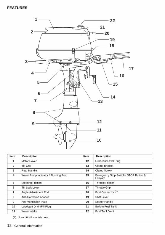
FEATURES
Item Description Item Description1 Motor Cover 12 Lubricant Level Plug
2 Tilt Grip 13 Clamp Bracket
3 Rear Handle 14 Clamp Screw
4 Water Pump Indicator / Flushing Port 15 Emergency Stop Switch / STOP Button & Lanyard
5 Steering Friction 16 Throttle Friction
6 Tilt Lock Lever 17 Throttle Grip
7 Angle Adjustment Rod 18 Fuel Connector (1)
(1) 5 and 6 HP models only.
8 Anti-Corrosion Anodes 19 Shift Lever
9 Anti-Ventilation Plate 20 Starter Handle
10 Lubricant Drain/Fill Plug 21 Built-in Fuel Tank
11 Water Intake 22 Fuel Tank Vent
1
2
3
4
5
67
8
9
10
11
12
1314
15
1617
1819
2021
22

General Information - 13
Item Description Item Description23 Choke Knob 28 Spark Plug
24 Oil Inspection Window 29 Starter Grip
25 Fuel Shut Off Valve 30 Engine Cover Bumpers
26 Fuel Tank (1)
(1) Not supplied in all marketing areas.
31 Emergency Starter Cord
27 Tool Kit
2928
30
23 25
24
27
26
31

14 - General Information
ENGINE SPECIFICATIONS
4, 5, 6 ModelsDisplacement 8.4 cu. in. (138 cc)
Engine Type Four-Cycle, In-line, 1 Cylinder
Full Throttle Operating Range 4 - 4000 to 5000 RPM5 - 4500 to 5500 RPM6 - 4750 to 5750 RPM
Power (1)
(1) Rated following the standards of ICOMIA 28.83, ISO 3046, and NMMA.
4 - 4 HP (2.9 kw) @ 4500 RPM5 - 5 HP (3.7 kw) @ 5000 RPM6 - 6 HP (4.5 kw) @ 5250 RPM
Idle RPM in Gear (2)
(2) Emission Control Information.
1300 ± 50
Ignition Timing – Idle (1)
W.O.T.Not AdjustableNot Adjustable
Exhaust Emission Control System:per SAE J1930 (1)
EM (Engine Modification)
Fuel Requirements (1) 87 Pump Posted AKI (90 RON) – Refer to Fuel and OilCrankcase – Oil
CapacityFilter
Evinrude®/Johnson® Ultra™ 4-Stroke synthetic blend oil – Refer to Fuel and Oil23.7 fl. oz. (0.7 Liter)See your Dealer
Starting Rope
Spark Plug (1)
TorqueRefer to ECI Label 11 to 14 ft. lbs. (15 to 19 N·m)
Gearcase - Lubricant Capacity
Evinrude/Johnson Ultra-HPF™ gearcase lubricant6.4 fl. oz. (189 ml)
Propeller 7 1/2 x 6 1/2
Fuel Tank (built in)Fuel Tank (portable) (3)
(3) Not supplied in all marketing areas.
Capacity – 0.4 U.S. Gallons (1.5 Liters)Capacity – 3 U.S. Gallons (11.4 Liters)
Weight S - 55.1 lbs. (26 kg)L - 57.3 lbs. (27 kg)
Transom Height S - 14 1/2 to 15 in. (368 to 381 mm)L - 19 1/2 to 20 in. (495 to 508 mm)
Sound at Driver’s Ear(LpA) ICOMIA 39.94
4 - 78.9 dB(A)5 - 80.5 dB(A)6 - 80.8 dB(A)
Vibration at Tiller (arms) Less than 2.5 m/s2

General Information - 15
EMERGENCY STOP SWITCH
If equipped, the emergency stop switch is on thesteering handle. Use of the emergency stop featureis highly recommended on all boats.Connect the clip to the emergency stop switch.Snap the lanyard to a secure place on the opera-tor’s clothing or life vest — not where it might tearaway instead of activating the stop switch. Discon-necting the clip and lanyard will stop the engine andprevent the boat from becoming a runaway if thedriver moves beyond the range of the lanyard. If thelanyard is too long, it can be shortened by knottingor looping it. DO NOT cut or retie the lanyard.
1. Emergency STOP switch
An extra clip is provided on the emergency stop lan-yard — another person can insert it in the stopswitch and start the motor in an emergency.
1
WARNINGAvoid knocking or pulling the clip off thestop switch during normal boating. Theresulting unexpected loss of forwardmotion can throw occupants forward, caus-ing injury.
Your emergency stop switch can be effec-tive only when in good working condition.At each outing, inspect clip and lanyard forcuts, breaks, or wear. Replace worn or dam-aged parts.
Keep the lanyard free from obstructions andentanglements.
At each outing, test the system’s operation.With the engine running, remove the clipfrom the switch by pulling the lanyard. If theengine does not stop running, see yourDealer.

16 - Fuel and Oil
FUEL AND OIL
FUEL
Your outboard is certified to operate on unleadedautomotive gasoline with an octane rating equal toor higher than that specified in Minimum Octanechart. When using gasoline that contains MTBE oralcohol, follow these guidelines:Using unleaded gasoline that contains methyl ter-tiary butyl ether (MTBE) is acceptable ONLY if theMTBE content does not exceed 15% by volume.Using alcohol-extended fuels is acceptable ONLY ifthe alcohol content does not exceed:10% ethanol by volume; or5% methanol with 5% cosolvents by volume
Minimum Octane
Your outboard has been designed to operate usingthe above fuels; however, be aware of the follow-ing:The boat’s fuel system may have different require-ments regarding the use of alcohol fuels. Refer tothe boat’s owner Guide.Alcohol attracts and holds moisture that can causecorrosion of metallic parts in the fuel system.Alcohol blended fuel can cause engine perfor-mance problems.
IMPORTANT: Always use fresh gasoline. Gasolinewill oxidize and weather; the result is loss of octane,volatile compounds, and the production of gum andvarnish deposits which can damage the outboard.
WARNINGGasoline is extremely flammable and highlyexplosive under certain conditions. Followthe instructions in this section explicitly.Improper handling of fuel could result inproperty damage, serious injury, or death.
Always turn off the engine before fueling.
Never permit anyone other than an adult torefill the fuel tank.
Do not fill the fuel tank all the way to the top,or fuel may overflow when it expands due toheating by the sun.
Remove portable fuel tanks from the boatbefore fueling.
Always wipe off any fuel spillage.
Do not smoke, or allow open flames orsparks, or use electrical devices such ascellular phones in the vicinity of a fuel leakor while fueling.
Always work in a well ventilated area.
Inside the U.S. 87 (R+M)/2 AKI
Outside the U.S. 91 RON
WARNINGLeaking fuel is a fire and explosion hazard.All parts in the fuel system should beinspected frequently and replaced if signsof deterioration or leakage are found.Inspect the fuel system each time yourefuel, each time you remove the enginecover, and annually.

Fuel and Oil - 17
OIL
Your 4-stroke engine requires oil in the crankcase.Evinrude/Johnson Ultra 4-Stroke syntheticblend oil is recommended for this outboard en-gine. It allows for extended oil change intervals andis best for high load applications. Evinrude/JohnsonUltra 4-Stroke synthetic blend oil delivers ultra vis-cosity stability, sludge protection, friction reducingproperties, and superior corrosion protection.If Evinrude/Johnson Ultra 4-Stroke synthetic blendoil is unavailable, you may use Evinrude®/Johnson® 4-Stroke outboard oil. This oil providesexcellent wear and corrosion resistance under nor-mal operating conditions. For your engine’s oil ca-pacity, refer to Engine Specifications.
IMPORTANT: Failure to follow this recommenda-tion could void the engine warranty if a lubrication-related failure occurs.
ADDITIVES
IMPORTANT: Only use fuel additives approved byBRP for your outboard. Use of other fuel additivescan result in poor performance or engine damage.Evinrude/Johnson 2+4® fuel conditioner willhelp prevent gum and varnish deposits from form-ing in fuel system components and will removemoisture from the fuel system. It can be used con-tinuously and should be used during any periodwhen your engine is not being operated on a regu-lar basis. Its use will reduce spark plug fouling, fuelsystem icing, and fuel system component deteriora-tion.
FUEL SYSTEM
IMPORTANT: Fuel distribution hoses in the boatmust deliver fuel at the rate of flow needed by theengine. Minimum inside diameter of fuel hosesmust be 5/16 in. (8 mm).Fuel systems with built-in tanks, particularly thosethat include antisiphon valves and filter/primerunits, may have restrictions that will not allow theengine fuel pump to deliver sufficient fuel under allconditions. This can result in a loss of performanceand possible engine damage. If a performanceproblem exists, see your Dealer.To avoid difficulty when restarting, never run theengine with the fuel hose disconnected, or run theengine out of fuel.
WARNINGIf your motor is equipped with a quick-dis-connect fuel hose, disconnect the fuel hosefrom the motor and from the fuel tank whenthe motor is not being used for a period oftime. Disconnecting the hose will avert fuelleaks in the hose or at the engine.

18 - Fuel and Oil
BREAK-IN (10 HOURS)
IMPORTANT: 4-Stroke outboards are shippedwithout oil in the crankcase. You must add oil tothe crankcase before starting the engine for thefirst time. It is recommended you add Evinrude/Johnson 4-Stroke outboard oil. Refer to Changingthe Oil for acceptable substitute lubricants.Follow this procedure to protect your new outboardduring its initial hours of operation. Careful break-inallows internal engine components to “seat” proper-ly, resulting in maximum engine performance.Failure to carefully follow the break-in procedurescan result in engine damage.High speed operation without sufficient enginewarm-up can result in engine damage.Perform the 10-Hour break-in procedure with theboat and engine in the water, using an appropriatepropeller.DO NOT perform break-in using a flushing device.DO NOT start-up or run the engine out of water.DO NOT leave a running engine unattended.
IMPORTANT: Before the start-up of your new en-gine:• Read Engine Starting, Engine Stopping and
Speed Control.• Check the crankcase oil level. Refer to Crank-
case Oil.• Perform prelaunch checks of all equipment.• Check the gearcase lubricant level. Refer to Lu-
brication.
Launch the boat and start the engine according tothe procedures in Engine Starting.• Verify water pump operation often. Look for a
steady stream of water from the water pump indi-cator. If the stream of water stops, shut off the en-gine to prevent damage. Find and correct thecause, or see your Dealer before you continue.
• Verify shift function by shifting into gear and ob-serving that the boat moves and that the move-ment is in the same direction as the shifter.
• Change the RPM often. Avoid holding a throttlesetting longer than 15 minutes.
• Check the crankcase oil level often. Add oil ifneeded.
First 10 minutes of operation — Operateengine in gear at idle only.
Balance of First 2 hours of operation — Oper-ate in gear below 3000 RPM or 1/2 throttle only.With easy planing boats, use full throttle to quicklyaccelerate boat onto plane. Immediately reducethrottle to one-half as soon as the boat is on plane.BE SURE boat remains on plane at this throttle set-ting.
Third hour of operation — Run the engine ingear at various speeds up to 4000 RPM or 3/4 throt-tle only.
Balance of first 10 hours of operation — Runthe engine in gear at various engine speeds includ-ing full throttle, but remain at full throttle no longerthan 5 minutes.Change the engine speed every 5 minutes.DO NOT exceed recommended maximum engineRPM. Refer to Engine Specifications.

Engine Starting - 19
ENGINE STARTING
BEFORE START-UP
Verify crankcase oil level before start-up. Refer toCrankcase Oil.Review and follow Break-In (10 hours) if the en-gine is new.You MUST supply water to the engine before at-tempting to start it. Engine damage can occurquickly. Refer to Engine Overheating or Flushing.Be sure the engine is in the normal operating posi-tion. Refer to Tilting.
Built-In Fuel TankOpen the vent screw on the fuel tank cap.• Clockwise to close.• Counterclockwise to open.
Turn the fuel shut-off valve aft. Fuel will flow fromthe built-in tank.
1. Fuel shut-off valve2. Built-in tank
Portable Fuel Tank (5 and 6 HP Models)Connect the fuel hose to the fuel connector.
DANGERDO NOT run the engine indoors or withoutadequate ventilation or permit exhaustfumes to accumulate in confined areas.Engine exhaust contains carbon monoxidewhich, if inhaled, can cause serious braindamage or death.
WARNINGThe engine cover is a machinery guard. DONOT operate your outboard with the coveroff unless you are performing maintenance,and then be careful to keep hands, hair, andclothing clear of all moving parts. Contactwith moving parts could cause injury.
WARNINGContact with a rotating propeller is likely toresult in serious injury or death. Assure theengine and prop area is clear of people andobjects before starting engine or operatingboat. Do not allow anyone near a propeller,even when the engine is off. Blades can besharp and the propeller can continue to turneven after the engine is off. Always shut offthe engine when near people in the water.
2

20 - Engine Starting
If equipped, open vent screw on fuel tank’s fillercap.Squeeze fuel primer bulb, outlet end up, until firm.
Turn the fuel cock lever forward. Fuel will flow to thecarburetor from the portable tank.
1. Fuel shut-off valve2. Portable tank
Switching from Portable to Built-In TankFollow these steps to switch to using the built-intank after the portable fuel tank becomes empty.1) Disconnect the fuel line of the portable tank
from the fuel connector on the outboard.2) Pour fuel into the built-in tank and wait 20
seconds before starting.3) Turn the fuel cock lever aft. Fuel will flow to
the carburetor from the built-in tank.
All ModelsIf equipped, attach the clip and lanyard assembly tothe emergency stop switch / STOP button. Snapthe lanyard to secure place on your clothing or lifevest.
1. Emergency stop switch / STOP button
Move the shift lever to NEUTRAL.
1. NEUTRAL
Start-up (Cold Engine)Pull the choke knob fully out. Twist the throttle gripto START position.
Start-up (Warm Engine)Align the arrow mark on the throttle grip with theSTART position. Do not use the choke.
1. Choke knob2. Throttle grip3. Start position
2
1 WARNINGAlways shift to NEUTRAL before startingthe engine to prevent sudden boat move-ment, which can cause injury.
1
1
1
2
3

Engine Starting - 21
While seated, grasp the starter handle and pullslowly until the starter engages, then pull hard. Al-low the starter cord to rewind slowly.If your engine doesn’t start after three pull, push thechoke knob in and repeat the starting procedure.Refer to Trouble Check Chart, if necessary.
1. Starter handle2. NEUTRAL
After Engine StartsGradually, push the choke in after the engine iswarm.Check the water pump indicator. A steady stream ofwater indicates the water pump is working. If asteady stream of water from the water pump indica-tor is not visible, stop the engine. Refer to EngineOverheating.
1. Water pump indicator
ENGINE STOPPING
Twist the throttle grip to IDLE position or slower.
Move the shift lever to NEUTRAL.
1. NEUTRAL
Press the stop button until the engine stops run-ning.
1. Emergency STOP switch / STOP button
12
1
1
1

22 - Engine Starting
SHIFTING AND SPEED CONTROL
IMPORTANT: Carefully check the function of allcontrol and engine systems before leaving thedock. DO NOT shift the engine into FORWARD orREVERSE while it is shut OFF.
ShiftingWith the engine running, twist the throttle grip toIDLE position.Move the shift lever briskly and completely FOR-WARD or REVERSE.
1. REVERSE2. FORWARD
Before shifting into NEUTRAL while boating, twistthe throttle grip to IDLE position, then wait until theengine slows to idle and the boat slows.
Speed ControlWith the engine running, twist the throttle grip:• Counterclockwise to increase speed• Clockwise to decrease speed
1. Increase speed2. Decrease speed3. Throttle grip
EMERGENCY STARTING
WARNINGExercise caution and use minimal speedwhen operating the boat in reverse. Be surethe shift lever is in desired position beforeaccelerating.
1 2
WARNINGWhen using Emergency Starting proce-dures, the start-in-neutral-only feature isinoperative. Make sure shift lever is in NEU-TRAL position to prevent injuries fromunexpected boat movement when theengine starts.
The engine cover is a machinery guard. Toprevent injury from moving engine compo-nents, keep hands, clothes, and hair clear ofpowerhead.
Prevent electric shock by keeping clear ofthe ignition coils and spark plug leads whenthe motor is being started or is running.Shock can cause serious personal injuryunder certain conditions.
DO NOT turn flywheel by hand. Use startercord only.
3
1 2

Engine Starting - 23
Move the shift lever to NEUTRAL.
1. NEUTRAL
Remove the engine cover.
Remove the bolts securing the recoil starter inplace.
Loosen the lock nut, take off the NSI cable from thebracket, and separate the end of the cable from thecam.
1. Lock nut2. Cam
Lift off the recoil starter assembly.Tie a knot in one end of the emergency starter cord.Tie the other end around the screwdriver handle inthe tool kit.Connect clip to the emergency stop switch / STOPbutton.Place knot of starter cord in notch on flywheel pul-ley. Wrap cord around pulley clockwise.Follow the starting procedure in Engine Starting.While seated, pull hard on emergency starting cordquickly and completely. Repeat, if necessary.
1. NEUTRAL
After starting, run the engine in NEUTRAL with thethrottle at the START position for two minutes.Then reduce speed to an idle.DO NOT attempt to replace manual starter or en-gine cover while engine is running. If equipped, at-tach emergency stop switch’s lanyard to a secureplace on your clothing.Proceed to nearest harbor for service.
1
12
1

24 - Operation
OPERATION
MOTOR ANGLE ADJUSTMENT
Motor should be perpendicular to the water whenthe boat is underway at full speed. This adjustmentcan only be determined by water testing the boat.Set angle adjustment for your normal load.Place motor in full tilt position. Refer to Tilting.Move angle adjusting rod as shown.
TILTINGIMPORTANT: Use the tilt grip to tilt your motor. Donot use the tiller handle to raise or lower the motor.
Tilt Lock LeverThe tilt lock lever is used to hold the motor in the fulltilt up position and shallow-water drive position.
Tilt UpMove the shift lever to NEUTRAL. Grip the tilt gripon the back of the motor cover and tilt the motor allthe way up until it is automatically locked in the UPposition by the tilt lock lever.
1. Tilt grip2. Tilt lock lever
IMPORTANT: DO NOT use the tilt lock lever whiletrailering. Refer to Trailering.
DANGERDO NOT run the engine indoors or withoutadequate ventilation or permit exhaustfumes to accumulate in confined areas.Engine exhaust contains carbon monoxidewhich, if inhaled, can cause serious braindamage or death.
WARNINGContact with a rotating propeller is likely toresult in serious injury or death. Assure theengine and prop area is clear of people andobjects before starting engine or operatingboat. Do not allow anyone near a propeller,even when the engine is off. Blades can besharp and the propeller can continue to turneven after the engine is off. Always shut offthe engine when near people in the water.
WARNINGDO NOT place your hands near the mount-ing bracket or under the motor when tilting,or they could be crushed if the motor slipsfrom your grasp.
WARNINGBe sure to turn the fuel lever forward beforetilting up the motor, or fuel will continue toflow from the built-in tank and fuel may leakout. When using a separate fuel tank (ifequipped), disconnect the fuel line when-ever you leave the motor tilted up for a longperiod of time, or fuel may leak out.
1 2

Operation - 25
Tilt DownGrasp tilt grip on engine cover and raise motorslightly. Pull up on the tilt lock lever. Slowly lowermotor to its normal operating position.
1. Tilt grip2. Tilt lock lever
SHALLOW-WATER DRIVE
There are two shallow-water drive positions. Usewhichever is appropriate, depending on the depthof the water.Slow the engine and shift to NEUTRAL before en-gaging or disengaging shallow-water drive.Slowly tilt the outboard up until you hear it make a“click” sound.Slowly lower the outboard. It will stop in a positionthat is slightly tilted up from the normal trim angle.
To lower the outboard back down, pull the motorslightly toward you, pull up on the tilt lock lever andslowly let the motor down.
1. Tilt grip2. Tilt lock lever3. NEUTRAL
IMPORTANT: Check often that water intakes arecompletely submerged and the water pump indica-tor is discharging a steady stream of water.
MOORING
You may moor your boat with the motor’s gearcaseout of the water by using its tilt feature. Dependingon the model, refer to Tilting.
1 2
WARNINGWhen using the shallow-water drive bracket,the tilt lock feature will not work. Operateyour motor in FORWARD and ONLY at slowspeed. The motor can tilt up forcibly anddrop suddenly if it hits an underwater objector if you shift to REVERSE and apply throt-tle. You could lose control.
1 2
3

26 - Operation
FLUSHING
See your Dealer for a flushing device designed to fityour engine. Follow manufacturer’s instructions forinstalling and using it.
Outboard — Running1) Place the engine in vertical position in a well-
ventilated area with good drainage.2) Remove the plug from the flushing port.3) Install flushing device and garden hose.4) Cover the water intake hole with tape.5) Place the shift lever in NEUTRAL with the
propeller removed.6) Start the water — keep pressure between 20
to 40 psi (140 to 300 kPa).
1. Flushing device2. Tape
7) Start the engine — run it at idle only andflush it for at least five minutes.
8) Shut OFF the engine, then turn off the water.9) Remove the tape and reinstall the flushing
port.10) Leave the outboard in vertical position long
enough to completely drain the powerhead.
DANGERDO NOT run the engine indoors or withoutadequate ventilation or permit exhaustfumes to accumulate in confined areas.Engine exhaust contains carbon monoxidewhich, if inhaled, can cause serious braindamage or death.
WARNINGPrevent injury from contact with rotatingpropeller; remove the propeller beforeflushing.
2
1

Operation - 27
ENGINE OVERHEATING
IMPORTANT: Do not run your engine — even for abrief start-up — without supplying water to it. Referto Flushing.While boating, the engine’s water intake must staycompletely submerged and unobstructed. Observeproper transom height and trim angle. While the en-gine is running, the engine’s water pump indicatormust discharge a steady stream of water. Checkthe indicator often, especially when operating inweeds, muddy and debris-laden water, at extremetrim angles, or in shallow water drive (if equipped).
1. Water pump indicator
If the stream from the water pump indicator be-comes intermittent or stops, reduce speed to idleand:Shift to NEUTRAL;SHUT OFF the engine;Tilt the motor up;Clean the intake screen of any blockage;Clean the water pump indicator of any blockage;Lower the motor; andRestart the engine and run at idle.IF cleaning the screen and indicator does not re-store the water pump indicator’s steady discharge,SHUT OFF the engine and do not attempt to oper-ate it. See your Dealer.IF cleaning the screen and indicator does restorethe water pump indicator’s steady discharge, con-tinue to idle the engine until it cools.
IMPORTANT: You must restore cooling to the en-gine to avoid serious engine damage.After any overheat, have your Dealer:Torque the cylinder head screws.Inspect the water pump for excessive wear or dam-age.Inspect the thermostats.Inspect the engine for leaks.Check engine oil level.
1

28 - Operation
TRAILERING
Trailer your boat with the motor in a vertical posi-tion. If your trailer does not provide adequate roadclearance, the motor can be trailered by using anaccessory trailering bracket. See your Dealer.DO NOT use the tilt lock lever when trailering.
IMPORTANT: Whenever using an accessory traile-ring bracket, the motor must be restrained. Bounc-ing during transport will damage the motor andboat’s transom.
IMPACT DAMAGEYour engine can be damaged from impact with un-derwater objects. Such impacts can result in seri-ous damage to your engine and injury to boatoccupants from the engine or its parts entering theboat. Occupants can also be ejected or injured byfalling against portions of the boat as a result of rap-id deceleration following impacts. When boating inunfamiliar, shallow, or debris-laden waters, seek in-formation on safe boating areas and navigationhazards from a reliable local source. Reduce yourspeed and keep a sharp lookout!
If you hit any object, stop immediately and examinethe engine for loosening of attaching hardware andclamp screws, if equipped. Inspect for damage toswivel and stern brackets, steering components,and components in the area of impact. Also, exam-ine the boat for structural damage. Tighten anyloosened hardware. If the collision occurred in thewater, proceed slowly to harbor. Before boatingagain, have your Dealer thoroughly inspect all com-ponents.
WARNINGFailure to inspect for damage could result insudden, unexpected component failure,loss of boat control, and personal injury.Unrepaired damage could reduce your boatand engine’s ability to resist future impacts.

Operation - 29
STORING
If you must tilt the motor to remove it from the water,lower it and allow the cooling system to drain com-pletely as soon as you clear the launch area.Between uses, store your motor in a vertical posi-tion.For recommendations on extended periods of stor-age, refer to Off-Season Storage.
CARRYING AND TRANSPORTING
If you will be laying the engine down, minimize thepotential for fuel spillage by letting it run “out of gas”before you remove it from the boat.Make sure that the engine has stopped completely.Turn the fuel shut off valve forward.If equipped, remove the fuel hose from the motor.Drain the gasoline from the carburetor by removingthe motor cover and loosening the carburetor drainscrew. Drain the gasoline into a suitable container.
1. Carburetor drain screw
After draining, retighten the drain screw.
Stand the motor vertically and drain water from thelower unit.
Horizontal transportDrain the gasoline from the carburetor.Raise the tiller handle and rest it on a padded sur-face on its port side. Protect the engine cover fromdamage.After removing the engine from the boat, position itupright until the cooling system stops draining.Keep the powerhead higher than the gearcase at alltimes, or any water remaining in exhaust passagescould travel to the cylinders and cause seriousdamage.
IMPORTANT: Do not rest the engine before thecooling water has drained completely, as watermay enter the cylinder through the exhaust port andcause problems.
IMPORTANT: Do not let the gearcase of the out-board sit higher than the powerhead during trans-porting or storing. Water may drain into thepowerhead, causing damage to the engine.
WARNINGUse a proper, safe container to store anygasoline drained from the outboard motor.
1

30 - Operation
SPECIAL OPERATING CONDITIONS
Salt WaterFlush the engine internally after use in salt, pollut-ed, or brackish water to help prevent mineral de-posits from clogging cooling passages. Youroutboard has a built-in flushing port to facilitateflushing. Refer to Flushing.During use in salt or brackish water, additional an-odic protection for the boat and outboard may be re-quired.During long periods of mooring, tilt the gearcase outof the water — except in freezing temperatures.Upon removal from salt water, leave it in a verticalposition until its cooling system has drained.
Weedy WaterWeeds block water intakes and cause your out-board to overheat. Weeds on the propeller createvibration and reduce boat speed.Run at slow speeds and in REVERSE frequently toclear weeds from the propeller and water intakes.Check the water pump indicator often.If REVERSE operation does not clear away weeds,SHUT OFF the engine. Remove weeds from pro-peller area and water intakes before operating athigher speed.
Boat Bottom and Engine External FinishThe condition of your boat’s bottom affects perfor-mance. A covering of marine growth reducesspeed. For maximum performance, keep the boat’srunning surface clean by wiping it dry after each useand washing it occasionally.After operating your outboard, rinse it with fresh wa-ter and wipe it dry. Apply Evinrude®/Johnson® anti-corrosion spray to any surface subject to corrosion,but avoid the anticorrosion anode(s).Periodically, wash the entire boat and outboard withsoapy water and apply a coat of automotive wax.Leave the engine cover in place when washing theoutboard.
High AltitudeIf you boat at altitudes above 3000 ft. (900 m), yourengine might benefit from a lower pitched propeller,different carburetor calibration, or both. See yourDealer.
IMPORTANT: To avoid permanent powerheaddamage, be sure that an engine modified for highaltitude operation is properly identified and returnedto original calibration and propeller size if operatedbelow 3000 ft. (900 m).
Shallow Water
IMPORTANT: Serious engine damage will occur ifthe gearcase is allowed to drag on the waterwaybottom.
Freezing WeatherDURING operation in freezing weather, keep thegearcase submerged at all times.Upon removing your motor from the water, leave itin a vertical position until its cooling system isdrained.
IMPORTANT: Water that has leaked into the gear-case, or remained in the cooling system or othercomponents can freeze, causing serious enginedamage.
Submerged EngineIf your engine has been under water, have it ser-viced immediately upon recovery. If immediateservice is unavailable, resubmerge it in fresh waterto avoid prolonged exposure to the atmosphere.After submersion, all boat and engine electrical, fu-el, and oiling systems must be inspected for signsof water intrusion. Your Dealer should perform thisservice.
Under TowShould you require a tow from another boat:• Shift your engine to NEUTRAL;• Tilt its gearcase out of the water; and• Off-load all persons into another boat.Keep towing speed slower than planing speed.

Maintenance - 31
MAINTENANCE
Maintenance, replacement, or repair of theemission control devices and systems may beperformed by any marine SI (spark ignition) en-gine repair establishments or individual.
ENGINE EMISSIONS INFORMATION
Manufacturer’s ResponsibilityBeginning with 1999 model year engines, manufac-turers of marine engines must determine the ex-haust emission levels for each engine horsepowerfamily and certify these engines with the UnitedStates of America Environmental Protection Agen-cy (EPA). An emissions control information label,showing emission levels and engine specifications,must be placed on each engine at the time of man-ufacture.
Dealer’s ResponsibilityWhen performing service on all Johnson outboardsthat carry an emissions control information label,adjustments must be kept within published factoryspecifications.Replacement or repair of any emission relatedcomponent must be executed in a manner thatmaintains emission levels within the prescribed cer-tification standards.Dealers are not to modify the engine in any mannerthat would alter the horsepower or allow emissionlevels to exceed their predetermined factory speci-fications.Exceptions include manufacturer’s prescribedchanges, such as altitude adjustments.
Owner ResponsibilityThe owner/operator is required to have enginemaintenance performed to maintain emission levelswithin prescribed certification standards.The owner/operator is not to, and should not allowanyone to, modify the engine in any manner thatwould alter the horsepower or allow emissions lev-els to exceed their predetermined factory specifica-tions.Tampering with the carburetor to change horse-power or modify emission levels beyond factorysettings or specifications will void the product war-ranty.
EPA Emission RegulationsAll new 2002 and more recent Johnson outboardsmanufactured by BRP are certified to the EPA asconforming to the requirements of the regulationsfor the control of air pollution from new watercraftmarine spark ignition engines. This certification iscontingent on certain adjustments being set to fac-tory standards. For this reason, the factory proce-dure for servicing the product must be strictlyfollowed and, whenever practicable, returned to theoriginal intent of the design. The responsibilities list-ed above are general and in no way a complete list-ing of the rules and regulations pertaining to theEPA requirements on exhaust emissions for marineproducts. For more detailed information on this sub-ject, you may contact the following locations:
VIA U.S. POSTAL SERVICE:Office of Mobile SourcesEngine Programs and Compliance DivisionEngine Compliance ProgramsGroup (6403J)401 M St. NWWashington, DC 20460
VIA EXPRESS or COURIER MAIL:Office of Mobile SourcesEngine Programs and Compliance DivisionEngine Compliance ProgramsGroup (6403J)501 3rd. St. NWWashington, DC 20001
EPA INTERNET WEB SITE:www.epa.gov
WARNINGOnly perform service procedures which aredetailed in this Operator’s Guide. Attempt-ing to perform maintenance or repair onyour outboard if you are not familiar withthe correct service and safety procedurescould cause injury or death.

32 - Maintenance
10-HOUR INSPECTION
After 10 hours of operation, your new engine will bebroken in and its mechanical parts will have seated.At that time, all systems should be checked and anyadjustments needed should be made.Your Dealer will perform this 10-Hour Inspection atyour request and expense (based on local rates),according to what your engine needs — refer to En-gine Maintenance and Inspection Schedule, 10-Hour Inspection for a partial list.Follow consistent preventive maintenance by hav-ing your Dealer check and service your engineonce a year or after each 100 hours of operation,whichever comes first.
OFF-SEASON STORAGE
You must protect against natural environmentalconditions that can be damaging to an outboardmotor. Temperature and humidity changes whileyour outboard motor is not in use can cause corro-sion of internal engine parts when they are not pro-tected. Fuel remaining in your fuel tank and in theengine will oxidize and weather which can result inloss of octane and can cause gum deposits in thefuel system. Your warranty does not cover enginefailure caused by these conditions. We strongly rec-ommend that you have your Dealer prepare youroutboard for the off-season.To do the off-season storage preparations yourself,gather the supplies and perform the following steps:
2+4 Fuel ConditionerTriple-Guard® greaseUltra-HPF gearcase lubricantStorage Fogging Oil spray canEvinrude/Johnson Ultra 4-Stroke syntheticblend oil
Stabilize the engine’s fuel supply with 2+4 FuelConditioner during the last hours of operation to en-sure proper stabilization, following instructionson the container for mixture. Be sure to run theengine long enough for the treated fuel to reachthe engine.
IMPORTANT: Provide a water supply to the engineand start it. Run the engine at idle only.To run the engine on a flusher, refer to Flushing.
Oil — Start the engine and run it at least five min-utes to warm the crankcase oil.Stop the engine and drain the crankcase while theengine is warm. Refill it with Evinrude/Johnson Ul-tra 4-Stroke synthetic blend oil. Refer to CrankcaseOil. Restart the engine and run it for a few minutesto circulate the fresh oil.
IMPORTANT: It is very important that the bearingsurfaces be coated with clean oil before entering aperiod of storage, so be sure you run the engine af-ter changing the oil.Stop the engine and turn off the water. Disconnectthe flushing device.
Spark Plugs — Remove and examine them.Spray fogging oil into the plug holes. Slowly rotatethe flywheel several rotations by hand to distributethe oil and to drain the water from the water pump.Clean and reinstall the spark plugs, or discard andreplace them, if necessary. Refer to Spark Plugs.
Fuel filter(s) — Clean or change.
Ignition, oil, and fuel systems — Check for mis-placed leads and damaged or deteriorated parts.Be sure starter solenoid terminal boot and all con-nectors are in place.
Screws, bolts, nuts — Tighten any that areloose.
WARNINGPrevent injury from moving engine compo-nents. Before starting the engine:
Shift it to NEUTRAL.
Keep hands, clothes, and hair clear of pow-erhead.
Remove the propeller if you use a flushingdevice.

Maintenance - 33
Propeller — Remove and examine. If damaged,see your Dealer. Clean the propeller shaft and lubri-cate it. Refer to Propeller.
Lubrication — Refer to Lubrication to drain andrefill the gearcase and for lubricating points on theengine.Touch up painted surfaces and wax the engine’sexterior. Store the engine on the boat (or an enginestand) in a vertical, self-draining position.If you cannot store the engine in the recommendedvertical position, be sure the cooling system isdrained completely.
IMPORTANT: Never place the gearcase higherthan the powerhead. Any water remaining in the ex-haust passages can run into the cylinders andcause serious damage.If you remove an "installed" engine, examine allhardware you loosened or removed from the en-gine and its steering, throttle, and shift systems.Replace damaged or missing parts with Evinrude/Johnson Genuine Parts, or equivalent.
Portable fuel tank — Disconnect the hose fromthe tank. Remove the hose from the engine if the fit-ting is a quick-disconnect. If not, and the hose is se-cured to the engine, leave it connected. Secure thehose to protect it.
PRE-SEASON SERVICE
Remove your outboard from storage and prepare itfor a season of reliable service by performing a gen-eral check and a few preventive maintenance pro-cedures.Examine all loosened or removed hardware andany steering, throttle, and shift systems. Replacedamaged or missing parts with Evinrude/JohnsonGenuine Parts or equivalent.
Engine Oil — Check the engine oil level. Refer toCrankcase Oil.With the propeller removed, check the gearcase forleakage. If leakage is evident, the gearcase sealsshould be replaced. See your Dealer.
Anticorrosion anodes — Check condition. Referto Anticorrosion Anodes.Install the propeller unless you will run the engineon a flusher for your pre-season servicing. If so, in-stall the propeller after you shut OFF the engineand disconnect the flusher. Refer to Flushing.Refer to Propeller to install the propeller.
Top off fuel tank with fresh fuel.Follow Engine Starting and start the engine. Let itidle while you:Observe running quality – if poor, refer to TroubleCheck Chart or see your Dealer.Observe water pump operation. Water must flowfrom the water pump indicator in a steady stream. Ifit does not, shut OFF the engine and investigate.Refer to Engine Overheating.Stop the engine and check the fuel system forleaks.
WARNINGStore fuel tanks in a well-ventilated area,away from heat and open flame. Preventescape of liquid or vapors which could acci-dentally ignite. Close the filler cap ventscrew, if equipped. Be sure the discon-nected fuel hose does not drip.
WARNINGFailure to carefully reattach the outboardand its control systems with factory-speci-fied hardware can result in sudden, unex-pected loss of boat control.
WARNINGPrevent accidental contact with a rotatingpropeller; always remove it when using aflusher to run the engine.
WARNINGFailure to check for fuel leakage could allowa leak to go undetected, resulting in fire orexplosion.

34 - Maintenance
CRANKCASE OIL
Initial Fill
IMPORTANT: 4-Stroke outboards are shippedwithout oil in the crankcase. You must add oil tothe crankcase before starting the engine for thefirst time. It is recommended you add Evinrude/Johnson 4-Stroke outboard oil. Refer to Changingthe Oil for acceptable substitute lubricants.BEFORE filling the crankcase for the first time, besure it is empty by checking the dipstick. Refer toChecking.After the first 10 hours of operation, replace thebreak-in lubricant with Evinrude/Johnson Ultra 4-Stroke synthetic blend oil. Refer to 10-Hour In-spection.
CheckingCheck the oil level when the engine is cold to en-sure an accurate reading.1) Place the engine in a vertical position.2) Check the oil level through the oil level in-
spection window.3) The oil window should be completely full.
IMPORTANT: Operating the engine with too muchor too little oil in the crankcase will damage it.
Changing the OilRefer to Engine Maintenance and InspectionSchedule for frequency.After the first 10 hours of operation, replace thebreak-in lubricant with Evinrude/Johnson Ultra 4-Stroke synthetic blend oil. Refer to 10-Hour In-spection.If Evinrude/Johnson Ultra 4-Stroke synthetic blendoil is temporarily unavailable, you may useEvinrude/Johnson 4-Stroke outboard oil or anequivalent FC-W-approved 10W-40 or 10W-50 oil.Drain (or siphon) the old oil after running the engineto warm it. Warm oil flows more quickly and com-pletely, containing more suspended sludge thancold oil. If you change the oil only once a season,time the work so the engine contains clean oil dur-ing storage.
1) With engine shut OFF, place the engine in avertical position and remove the upper en-gine cover.
2) Unscrew and remove the oil fill cap.
1. Oil fill cap
CAUTIONUsed motor oil may be harmful. Avoid pro-longed and repeated skin contact. Washaffected skin with soap and water.
1

Maintenance - 35
3) Fully steer the outboard to the starboard side.4) Hold a suitable container under the oil drain
screw. Remove the screw and drain the re-servior. Before you reinstall the screw, re-place the gasket with a new one. Reinstall thescrew and tighten it securely.
5) Pour the recommended oil into the oil fill untilit reaches the upper mark on the dipstick. Re-fer to Engine Specifications for crankcasecapacity.
6) Replace the oil fill cap and clean any spilledoil off the engine and your skin.
7) Reinstall the upper cover.8) Supply water to the cooling system and run
the engine at idle to check for leaks, especial-ly around the oil filter, drain screw and oil fillcap. Correct any problems.
9) Stop the engine and recheck crankcase oillevel using the dipstick. Add oil as indicated.
1. Upper limit2. Lower limit
Dispose of used oil in a reasonable manner follow-ing all local regulations.
ADJUSTMENTS
Throttle FrictionAdjust until a slight drag is felt when accelerating ordecelerating only. DO NOT overtighten. If adjust-ment is necessary, turn the adjustment screw:• Clockwise to increase friction• Counterclockwise to decrease friction
1. Throttle friction screw
Steering FrictionThe steering friction was set on your new motor be-fore it left the factory. After the first 10 hours of ser-vice, check to see that it is still correct; a slight dragshould be felt when turning the motor. If adjustmentis necessary, turn the adjustment screw:• Clockwise to increase friction• Counterclockwise to decrease friction
1. Steering friction screw
1
2
WARNINGDO NOT overtighten for “hands-off” steer-ing. Reduced steering control could result.
1
1

36 - Maintenance
LUBRICATION
GearcaseReplace gearcase lubricant after first 10 hours ofoperation. Check level and condition of lubricant af-ter next 50 hours of operation. Add lubricant if nec-essary.Thereafter, check level and condition of lubricantevery 50 hours. Replace lubricant every 100 hoursof operation or once each season, whichever oc-curs first. Refill with Ultra-HPF gearcase lubricant.If not available, Hi-Vis™ or other marine gearcaselube can be used, however, long term durabilitymay be affected with continued use. See your Deal-er.
IMPORTANT: The recommended gear lubricantsinclude special additives for marine applications.Do not use automotive gear lubricants, 2-stroke or4-stroke engine oil, or any other oil or grease forgearcase applications.With motor in normal operating position:1) Remove drain/fill plug and lubricant level plug
from side of gearcase and completely draingearcase of old lubricant.
2) Examine drained lubricant for metal filings,milky appearance, or black color with burntodor. If old lubricant has any of those charac-teristics, see your Dealer. If drained lubricantis in good condition, continue.
3) Place tube of lubricant in drain/fill hole and fillslowly until lubricant appears at lubricant lev-el hole. See Engine Specifications for gear-case capacity.
4) Install lubricant level plug before removingtube from drain/fill hole. Drain/fill plug canthen be installed without loss of lubricant.
5) Securely tighten both plugs.
1. Drain/fill plug2. Lubricant level plug
IMPORTANT: To avoid insufficient injection of lu-bricant, check the gear oil level 10 minutes after fill-ing. If the oil level is low, slowly inject the lubricantup to the correct level.

Maintenance - 37
Lubrication PointsRefer to Engine Maintenance and InspectionSchedule for lubrication frequency and recom-mended lubricant.
1. Throttle linkage
1. Shift lever2. Steering bracket
1. Propeller shaft
1. Clamp screws
1. Swivel bracket
1
1
2
1
1
1

38 - Maintenance
BREATHER AND FUEL LINE
Inspect the breather and fuel line for leaks, cracks,swelling, or other damage. If the breather and fuelline are damaged in any way, they must be re-placed. See your Dealer.
SPARK PLUGS
Inspect spark plugs periodically. Replace if elec-trodes are badly worn, insulators are cracked, or ifthey are badly fouled.To remove spark plugs, twist and remove all sparkplug leads. Unscrew spark plug from cylinder head. To install spark plugs, wipe spark plug seats cleanwith a clean rag. Install spark plugs finger tight, thentighten to specified torque. Refer to Engine Speci-fications.
IMPORTANT: Avoid engine damage by installingspark plugs into COOL cylinder head and not over-tightening.Before installing the spark plug lead, apply a lightcoat of Triple-Guard grease to the ribbed portion ofthe spark plug. This will help prevent corrosion be-tween the spring terminal and the spark plug.
1. Ribbed portion of the spark plug
WARNINGLeaking fuel is a fire and explosion hazard.All parts in the fuel system should beinspected frequently and replaced if signsof deterioration or leakage are found.Inspect the fuel system each time yourefuel, each time you remove the enginecover, and annually.
WARNINGThe ignition system presents a seriousshock hazard. The primary circuit operatesin excess of 250 volts; the secondary circuitoperates in excess of 25,000 volts. Use cau-tion to avoid injury from shock or injuryresulting from your reaction to shock. Donot handle primary or secondary ignitioncomponents while the engine is cranking orrunning.

Maintenance - 39
PROPELLER
IMPORTANT: Apply Triple-Guard grease to the en-tire propeller shaft before installing the propeller. Atleast annually, remove the propeller and check fordebris. Clean the shaft and regrease it before rein-stalling a propeller.
Installation1) Install the stopper on the shaft.2) Slide the propeller onto the shaft.3) Install propeller nut and tighten securely.4) Align the hole in propeller nut with hole in pro-
peller shaft. Insert the cotter pin and bend itsends over to lock in place.
1. Stopper2. Propeller3. Propeller nut4. Cotter pin
RepairIf your propeller hits a solid object, the impact is par-tially absorbed by the rubber bushing in the hub tohelp prevent damage to the engine. A strong impactcan damage the hub and propeller blades. Damageto blades can cause unusual and excessive vibra-tion. Damage to the hub can cause excessive en-gine RPM with little forward movement.
IMPORTANT: Avoid or limit operation using a dam-aged propeller. Carry a spare propeller.Keep your propeller in good condition. Use a file tosmooth slight damage to blade edges. See yourDealer for repair of serious damage.
ANTICORROSION ANODES
Your motor is equipped with one or more anodesthat protect it from galvanic corrosion. Refer to Fea-tures for anode location. Disintegration of the an-ode is normal and indicates it is working. Checkeach anode periodically. Replace anodes smallerthan 2/3 their original size. See your Dealer for re-placements.
Galvanic corrosion destroys underwater metalparts and can occur in fresh or salt water; however,salt, brackish and polluted waters will acceleratecorrosion.Metal-based antifouling paint on the boat or motorand the use of improperly installed shore power inthe area of your moored boat will also acceleratecorrosion.
IMPORTANT: NEVER paint the anode, its fasten-ers, or its mounting surface. Painting will reduce itscorrosion protection.
WARNINGTo avoid accidental starting of engine whilechanging propellers, twist and remove allspark plug leads.
1234

40 - Maintenance
TROUBLE CHECK CHART
IMPORTANT: If you are unable to identify or solve the problem, contact your Dealer.
SYMPTOM POSSIBLE CAUSEEngine will not start • Not following starting instructions. Refer to Engine Starting Sec-
tion.• Fuel tank empty.• Fuel hose disconnected, kinked.• Fuel system contaminated with water or dirt.• Fuel filter obstructed.• COLD ENGINE: Engine not choked• WARM ENGINE: Engine flooded. Disconnect fuel hose at engine,
push in choke or primer, crank engine. If it starts, run until cleared.If it fails to start, wait a few moments and try again.
• Spark plugs incorrect. Refer to Engine Specifications.• Spark plugs improperly gapped, carboned, burned or wet.• Ignition system component failure.
Engine will not idle properly • Motor angle excessive.• Spark plugs damaged or incorrect. Refer to Engine Specifica-
tions.• Fuel system contaminated with water or dirt.
Engine loses power • Spark plugs damaged or incorrect. Refer to Engine Specifica-tions.
• Fuel filter obstructed.• Fuel system contaminated with water or dirt.• Water intakes obstructed and cooling system not operating cor-
rectly. Refer to Engine Overheating.Engine vibrates excessively • Propeller shaft bent.
• Propeller fouled and restricted, blades bent or broken.• Fuel system contaminated with water or dirt.• Engine mount(s) damaged.• Steering friction screw loose.
Engine runs, but makes little or no progress
• Propeller hub loose, slipping.• Propeller blades bent or missing.• Propeller shaft bent.• Propeller fouled and restricted.

Maintenance - 41
ENGINE MAINTENANCE AND INSPECTION SCHEDULE
Routine maintenance is necessary for all mechanized products. Periodic maintenance contributes to theproduct’s life span. The following maintenance chart provides guidelines for engine maintenance and in-spection scheduled to be performed by you and/or by an authorized Dealer. The schedule should be ad-justed according to operating conditions and use.The recommended lubricants have been formulated to protect bearings, gears and engine components.They must be used to avoid damage caused by improper lubrication.
IMPORTANT: Schedules for rental operations, commercial applications or high hour use will requiregreater frequency of inspection and maintenance.
Engine Maintenance and Inspection Schedule
DescriptionEngine Care Product
Frequency
Each
Use
10-H
our
Insp
ectio
n
Ever
y 50
Hou
rs
or 6
mon
ths
Ever
y 10
0 H
ours
or
Ann
ually
Ever
y 20
0 H
ours
or
Bia
nnua
lly
Swivel bracket, inspect and lubricate (1) 7 Every 60 days / Every 30 in Saltwater
Throttle linkage, inspect and lubricate (1) 7 Every 60 days / Every 30 in Saltwater
Clamp screws, lubricate (1) 7 Every 60 days / Every 30 in Saltwater
Shift lever, lubricate (1) 7 Every 60 days / Every 30 in Saltwater
Steering bracket, lubricate (1) 7 Every 60 days / Every 30 in Saltwater
Lubrication and corrosion protection for metallic components
4 Every 60 days / Every 30 in Saltwater
Anticorrosion anodes and bonding wires, verify operation
O D
Water intake screens, verify condition O D
Overboard water pump indicator, verify operation O D
Steering friction check, adjust/tighten O D
Throttle and shift operation, verify function O D
Emergency stop circuit and lanyard, verify function O D
Crankcase oil level, check O D
Flush cooling system O
Clamp screws, tighten O
Emergency start cord, onboard and inspect O
Operator’s Guide, onboard O
Engine upper and lower motor covers, clean and wax O
Operator’s Guide, review O
Fuel components, inspect and repair leaks (2) D D
Fastener inspection, tighten loosened components D D
Thermostat, verify operation (2) D D
Engine to transom mounting hardware, re-torque D D
Electrical and ignition wires and connections, inspect D D
Gearcase lubricant replace 5 D D
Powerhead synchronization and linkage, inspect (2) D D
Crankcase oil, replace 11 D D
Crankcase oil filter, replace D D

42 - Maintenance
Valve tappet clearance, inspect (2) D D
Gearcase lubricant, inspect fill level and condition of lube
5 D
Spark plugs, replace (2) D
Propeller shaft, inspect and lubricate 7 D
Decarbonize 10 D
Driveshaft splines, inspect and lubricate 8 D
Water pump, inspect and replace D
Breather and fuel line, replace D
Carburetor, inspect D
Fuel filter, replace D
Ignition timing, check D
(1) Also recommended at 10-Hour Inspection
(2) Emission-related component
D Dealer Performed Service
O Operator Performed Service
4 Evinrude/Johnson anti-corrosion spray or Evinrude/Johnson “6 in 1” multi-purpose lubricant
5 Ultra-HPF gearcase lubricant
6 Power Trim/Tilt Fluid
7 Triple-Guard grease
8 Evinrude/Johnson Molylube P/N 175356
9 Starter Bendix Lube Only P/N 337016
10 Evinrude/Johnson engine tuner
11 Evinrude/Johnson Ultra 4-Stroke synthetic blend oil
Engine Maintenance and Inspection Schedule
DescriptionEngine Care Product
Frequency
Each
Use
10-H
our
Insp
ectio
n
Ever
y 50
Hou
rs
or 6
mon
ths
Ever
y 10
0 H
ours
or
Ann
ually
Ever
y 20
0 H
ours
or
Bia
nnua
lly

Installation - 43
INSTALLATION
TRANSOM HEIGHT AND SHAFT LENGTH
The transom height dimension listed in EngineSpecifications, is the height of the boat transomyour engine needs. This dimension is measured atthe transom centerline, perpendicular to the bottomof the boat.
1. Transom Height2. Anti-ventilation Plate3. Final position - 0 to 1 in. (0 to 25 mm)
Use this procedure to determine whether or not theboat’s transom height is correct for the engine’sshaft length:Set the motor on the boat’s transom and adjust theangle so the anti-ventilation plate is parallel with theboat bottom. Refer to Motor Angle Adjustment.
WARNINGYour engine must not exceed the maximumhorsepower indicated on the boat’s capacityplate. Such overpowering can cause loss ofcontrol. Contact your Dealer or the boat’smanufacturer if your boat lacks a capacityplate.
Boats designed for remote-steered enginesmight be overpowered by a tiller-steeredengine of the maximum rated horsepower.Ask your Dealer or boat manufacturer if youare unsure about your boat’s suitability.
Incorrectly matched boat and engine tran-som heights can cause boat instability andloss of control. Refer to Transom Height andShaft Length.
Prevent lateral movement and possibleengine loss by using the mounting hard-ware supplied or hardware of sufficient size,strength, and quality. Refer to Installing theEngine.
A mounting surface that is damaged or toothin to support your engine while underwaymight fail during operation, causing you tolose control. Be sure the boat’s transom ormounting bracket is structurally sound andbetween 1 5/8 in. (41 mm) and 2 3/4 in. (70mm) in thickness.

44 - Installation
The resulting position of the anti-ventilation platemust be 0 to 1 in. (0 to 25 mm) below the boat’s bot-tom.
IMPORTANT: If the anti-ventilation plate falls out-side the 0 to 1 in. (0 to 25 mm) range, the installa-tion is not considered normal. The motor shaftlength must be changed or the boat’s transom mustbe modified.Lower than recommended – serious powerheaddamage could result from water entry into the lowerengine cover or overloading from an under-revvingpropeller at wide open throttle.Higher than recommended – serious powerheaddamage could result from inadequate cooling or anover-revving propeller. Propeller ventilation (slip-page) often occurs, resulting in poor boat perfor-mance.On a specialty hull, non-planing hull, or on a boatwith a curved transom, these guidelines might notapply. See your Dealer for special installation infor-mation.
INSTALLING THE ENGINE
Center the engine on the boat’s transom (or mount-ing bracket) and tighten the clamp screws by hand,NOT with tools. See your Dealer for an accessorytransom plate to protect the boat’s transom.
1. Clamp screws2. Accessory transom plate
Bolt your engine to the boat’s transom using 8 mmbolts, washers, lock washers, and nuts.After positioning the engine, use the stern bracketsas a template for location and size of holes to drill inthe transom.Drill two holes of the proper size through the tran-som. Be sure to drill holes at right angles to the tran-som.Apply a good waterproof caulk generously behindthe heads and to the shanks of the mounting boltsbefore inserting them and to the surfaces of wash-ers that contact the transom. Avoid RTV siliconeand polyurethane sealants as they can be dis-solved by gasoline.Secure the engine with the mounting hardware po-sitioned as shown.After 30 minutes of operation, retighten clampscrews by hand. DO NOT use tools to tighten clampscrews. Check clamp screws regularly.
WARNINGWhen replacing bolts, screws, and otherfasteners, use Evinrude/Johnson GenuineParts or parts of equivalent strength andmaterial.

Installation - 45
CHANGE OF ADDRESS / CHANGE OF OWNERSHIPIf your address has changed or if there has been a change of ownership, be sure to fill out and mail thecard provided on this page.Such notification is likewise necessary for your own safety even after expiration of the original warranty,since BRP will be in a position to contact you if correction to your outboard becomes necessary.Outside the U.S. and Canada, this card should be sent to the Bombardier Recreational Products divisionwhere the outboard was registered. Please contact your Dealer or distributor.
000063
Change of address Change of ownership
Model number
Serial Number
Old address / Previous ownerLast name
First name M.I.
Address
City State
Zip code Country
Phone number
Signature Date
New address / New ownerLast name
First name M.I.
Address
City State
Zip code Country
Phone number
Signature Date

46 - Installation
Bombardier Recreational ProductsEvinrude / JohnsonDealer Support Services250 Seahorse DriveWaukegan, IL 60085

Installation - 47
Operator’s GuideConfirmation of Receipt
Your Dealer
Upon delivery of your new Evinrude/Johnson Outboard, complete and sign the form hereunder. YourDealer will take receipt of the form for their records.
Receipt
Name:
Address:
Name:
Address:
Owner of Model No:
Serial No:(To be completed by customer or selling Dealer)
The Dealer named on this document has instructed me on the operation, maintenance, safety features and warranty policy, all of which I understand and agree to be bound with. I am also satisfied with the predelivery set-up and inspection of my Evinrude/Johnson Outboard. I have also received a copy of the Operator’s Guide.
Signature:
Date:

48 - Installation
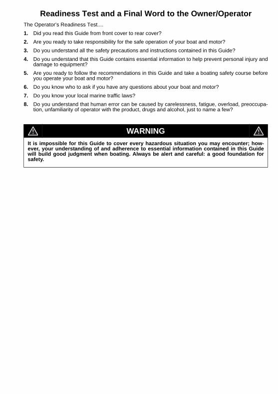
Readiness Test and a Final Word to the Owner/OperatorThe Operator’s Readiness Test....1. Did you read this Guide from front cover to rear cover?2. Are you ready to take responsibility for the safe operation of your boat and motor?3. Do you understand all the safety precautions and instructions contained in this Guide?4. Do you understand that this Guide contains essential information to help prevent personal injury and
damage to equipment?5. Are you ready to follow the recommendations in this Guide and take a boating safety course before
you operate your boat and motor?6. Do you know who to ask if you have any questions about your boat and motor?7. Do you know your local marine traffic laws?8. Do you understand that human error can be caused by carelessness, fatigue, overload, preoccupa-
tion, unfamiliarity of operator with the product, drugs and alcohol, just to name a few?
WARNINGIt is impossible for this Guide to cover every hazardous situation you may encounter; how-ever, your understanding of and adherence to essential information contained in this Guidewill build good judgment when boating. Always be alert and careful: a good foundation forsafety.
