otto bock tf design - pcs product...
TRANSCRIPT

Lesson Error! Style not defined.
Seminar TF Design – General Information 1
Notes
Otto Bock TF Design When working on jobs in the Otto Bock TF Design software, you go
through four program stages, each of which has a tab in the TF Design
processing window:
Specification Selection of the socket-specific data and entry of the patient
measurements. In order to enter the patient measurements, you
have to previously determine the exact values with the patient.
Socket View
Three-dimensional view of the calculated prosthesis socket, with the
option to make corrections.
Component Selection
Selection of components for the prosthesis.
Ordering
Display and editing of the purchase order for the current job.

Lesson Error! Style not defined.
Seminar TF Design – General Information 2
Notes
Because every socket design is based on relatively few measurements,
it is important that these measurements are taken carefully.
Repeating each measurement once or twice is recommended in order
to ensure that the values obtained are reliable.
Make a note of all measurements taken so you can subsequently
enter them in the software.
Before you begin working with the Otto Bock TF Design application,
take the following patient measurements:
Residual limb length
Residual limb circumference
Measurements with liner
Bony ML dimension
Soft tissue ML dimension
Lesson Error! Style not defined.
Seminar TF Design – General Information 3
Notes
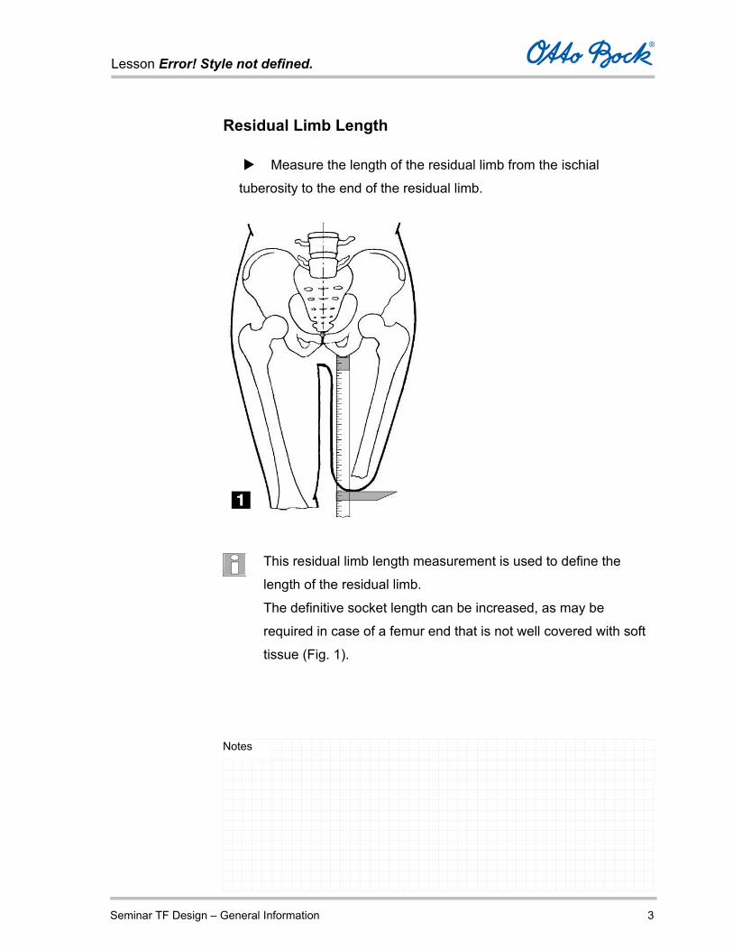
Residual Limb Length
Measure the length of the residual limb from the ischial
tuberosity to the end of the residual limb.
This residual limb length measurement is used to define the
length of the residual limb.
The definitive socket length can be increased, as may be
required in case of a femur end that is not well covered with soft
tissue (Fig. 1).
Lesson Error! Style not defined.
Seminar TF Design – General Information 4
Notes
Palpate the skin in order to place the body caliper firmly against
the ischial tuberosity. The residual limb musculature must be relaxed
when doing so, in order to keep the body caliper from slipping off.
Exert only light pressure on the end of the residual limb when
determining the length of the residual limb.
Use the Otto Bock Body Caliper 743S10, which will provide you
with a reliable residual limb length measurement.
Take the measurement along the residual limb axis.
If the residual limb is in a highly abducted position, tilt the body
caliper accordingly.
Lesson Error! Style not defined.
Seminar TF Design – General Information 5
Notes
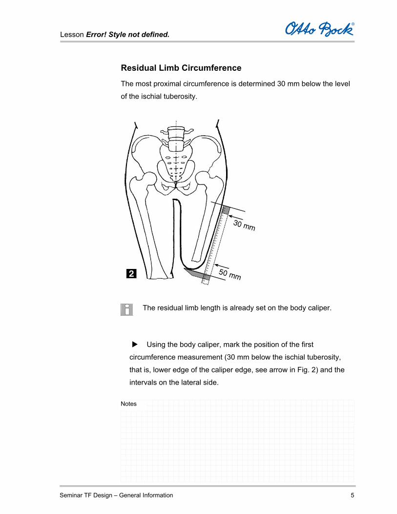
Residual Limb Circumference
The most proximal circumference is determined 30 mm below the level
of the ischial tuberosity.
The residual limb length is already set on the body caliper.
Using the body caliper, mark the position of the first
circumference measurement (30 mm below the ischial tuberosity,
that is, lower edge of the caliper edge, see arrow in Fig. 2) and the
intervals on the lateral side.
Lesson Error! Style not defined.
Seminar TF Design – General Information 6
Notes
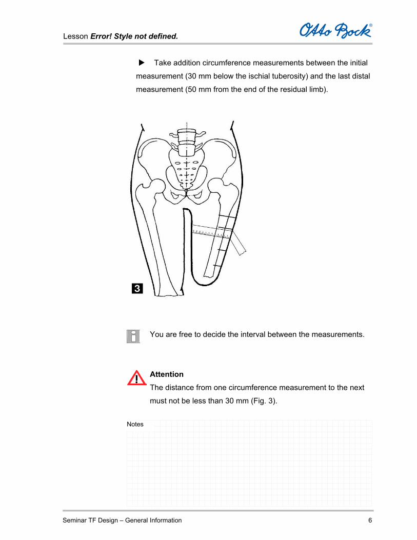
Take addition circumference measurements between the initial
measurement (30 mm below the ischial tuberosity) and the last distal
measurement (50 mm from the end of the residual limb).
You are free to decide the interval between the measurements.
Attention
The distance from one circumference measurement to the next
must not be less than 30 mm (Fig. 3).

Lesson Error! Style not defined.
Seminar TF Design – General Information 7
Notes
Take a total of no more than five measurements, including the initial
measurement and the last distal measurement (50 mm from the end of
the residual limb)
Attention
Additional measurements closer than 50 mm from the end of the
residual limb should not be taken, since the measurement
accuracy becomes very poor due to rounding of the residual
limb.
All measurements should represent the mean values of the muscles in
a tense and the muscles in a relaxed state.
When using measuring tape 743B1, try to keep the tension
constant while measuring or use the 743B4 spring-loaded
measuring tape.
Attention
Ensure that the measuring tape is horizontal in relation to the
axis of the residual limb.

Lesson Error! Style not defined.
Seminar TF Design – General Information 8
Notes
Measurements with Liner
First determine the correct liner size according to the application
instructions provided by the manufacturer.
After selecting the right liner size, the liner is rolled over the
residual limb before measuring. The circumference and length are
now determined with the liner applied, as previously described under
Residual Limb Circumference.
Applying the liner compresses the residual limb and therefore
causes a volume reduction.
Therefore we recommend not to apply any further reduction in
the software and to evaluate the reduction at 0%.
The exact socket length measurement is also determined by measuring
with the liner applied.
Lesson Error! Style not defined.
Seminar TF Design – General Information 9
Notes
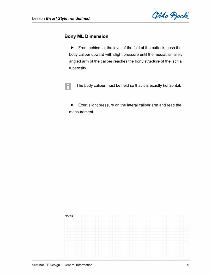
Bony ML Dimension
From behind, at the level of the fold of the buttock, push the
body caliper upward with slight pressure until the medial, smaller,
angled arm of the caliper reaches the bony structure of the ischial
tuberosity.
The body caliper must be held so that it is exactly horizontal.
Exert slight pressure on the lateral caliper arm and read the
measurement.
Lesson Error! Style not defined.
Seminar TF Design – General Information 10
Notes
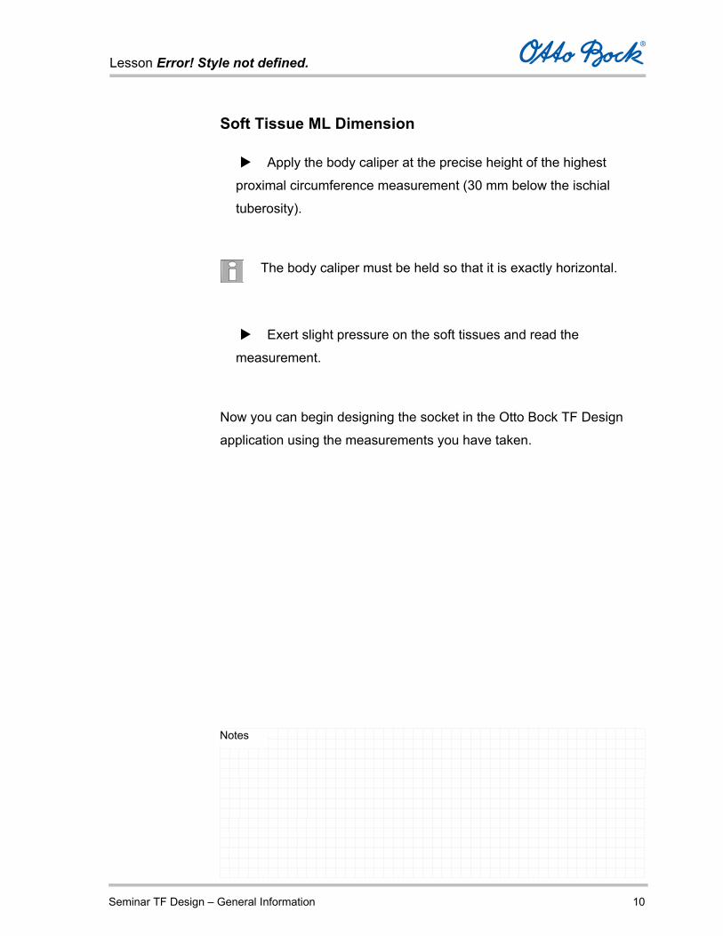
Soft Tissue ML Dimension
Apply the body caliper at the precise height of the highest
proximal circumference measurement (30 mm below the ischial
tuberosity).
The body caliper must be held so that it is exactly horizontal.
Exert slight pressure on the soft tissues and read the
measurement.
Now you can begin designing the socket in the Otto Bock TF Design
application using the measurements you have taken.

Lesson Error! Style not defined.
Seminar Otto Bock TF Design – Operating Example 1
Notes
Operating Example for the Otto Bock Data Station On the following pages, you will find a brief sample description of the
following operating steps:
Launching the Otto Bock Data Station
Creating patient data for a patient
Creating the group My Patients and assigning the new patient
to this group
Opening a job in TF Design for this patient
Submitting the purchase order to Otto Bock after the job is
completed
Closing the Otto Bock Data Station
Lesson Error! Style not defined.
Seminar Otto Bock TF Design – Operating Example 2
Notes
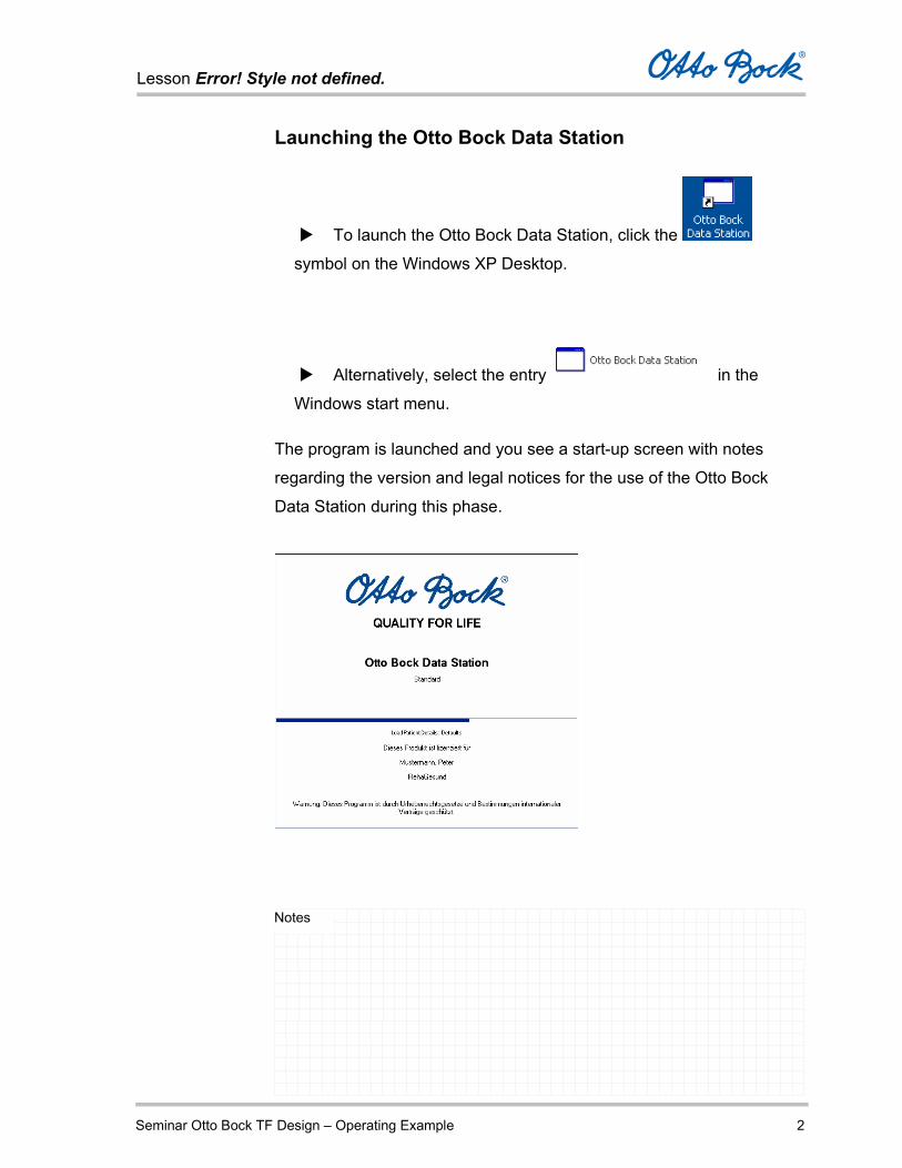
Launching the Otto Bock Data Station
To launch the Otto Bock Data Station, click the
symbol on the Windows XP Desktop.
Alternatively, select the entry in the
Windows start menu.
The program is launched and you see a start-up screen with notes
regarding the version and legal notices for the use of the Otto Bock
Data Station during this phase.
Lesson Error! Style not defined.
Seminar Otto Bock TF Design – Operating Example 3
Notes
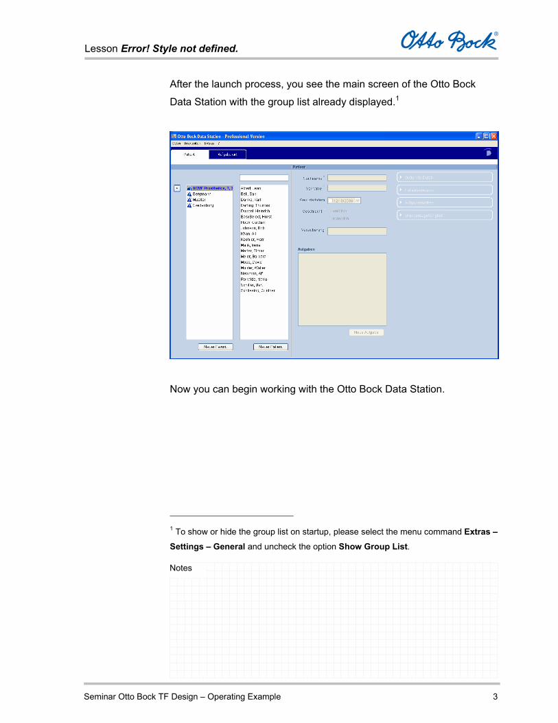
After the launch process, you see the main screen of the Otto Bock
Data Station with the group list already displayed.1
Now you can begin working with the Otto Bock Data Station.
1 To show or hide the group list on startup, please select the menu command Extras – Settings – General and uncheck the option Show Group List.

Lesson Error! Style not defined.
Seminar Otto Bock TF Design – Operating Example 4
Notes
Creating patient data for a patient
Create the patient data for a new patient named Theodor Müller.
Click the button New Patient.
Enter the last name and first name.
Open the Date of Birth field and select the date of birth from
the calendar.
Select the Gender of the patient.
In the Insurance field, you can enter a note regarding the
patient’s health insurance coverage.

Lesson Error! Style not defined.
Seminar Otto Bock TF Design – Operating Example 5
Notes
Up to this point, you have entered the following data.
Click the button Optional Data and enter additional data for the
patient.

Lesson Error! Style not defined.
Seminar Otto Bock TF Design – Operating Example 6
Notes
Click the button Patient Notes and enter a note or use the Add Photo button to load an image file with special pathology
characteristics.
To save the patient information you have entered, press Ctrl+S
or select the menu command File – Save.
Lesson Error! Style not defined.
Seminar Otto Bock TF Design – Operating Example 7
Notes
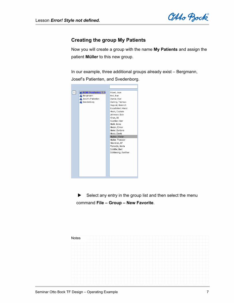
Creating the group My Patients
Now you will create a group with the name My Patients and assign the
patient Müller to this new group.
In our example, three additional groups already exist – Bergmann,
Josef’s Patienten, and Svedenborg.
Select any entry in the group list and then select the menu
command File – Group – New Favorite.

Lesson Error! Style not defined.
Seminar Otto Bock TF Design – Operating Example 8
Notes
In the Create Group window, enter the new group name My Patients and confirm by clicking the OK button.
The new group is inserted into the group list.
Now you will assign the new patient Theodor Müller to your group My Patients.
To do so, select the patient name in the patient list and drag the
entry onto the group name My Patients using the mouse. Then
release the mouse button; the entry is assigned to this group.

Lesson Error! Style not defined.
Seminar Otto Bock TF Design – Operating Example 9
Notes
You will see the new assignment.

Lesson Error! Style not defined.
Seminar Otto Bock TF Design – Operating Example 10
Notes
You can also verify the assignment by selecting the patient name
and clicking the button Group Membership.
The group memberships of the selected patient are displayed in
the window. This is useful if a patient entry is assigned to several
groups.
To remove a patient entry from a group, select the entry and
press Delete or select the command Remove Patient from the
context menu (right mouse button).
Lesson Error! Style not defined.
Seminar Otto Bock TF Design – Operating Example 11
Notes
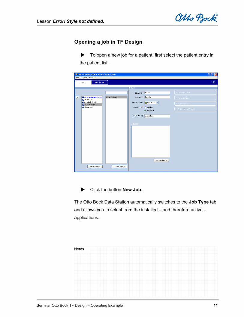
Opening a job in TF Design
To open a new job for a patient, first select the patient entry in
the patient list.
Click the button New Job.
The Otto Bock Data Station automatically switches to the Job Type tab
and allows you to select from the installed – and therefore active –
applications.
Lesson Error! Style not defined.
Seminar Otto Bock TF Design – Operating Example 12
Notes
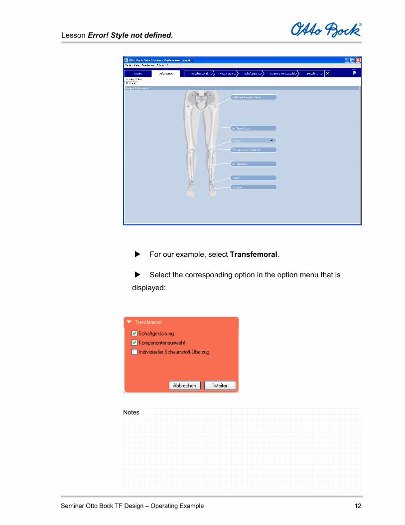
For our example, select Transfemoral.
Select the corresponding option in the option menu that is
displayed:
Lesson Error! Style not defined.
Seminar Otto Bock TF Design – Operating Example 13
Notes
Socket Design – Create a TF Design socket by entering
measurements and editing the Socket View.
Component Selection – Select additional components to
supplement the socket (prosthesis components).
Individual Foam Cover – you can leave this option deselected
for our operating example.
You will now finish processing the job Transfemoral Socket for the
patient Theodor Müller.
Click Next to move to the Specification tab.
There you can enter measurements and information regarding the
socket material.

Lesson Error! Style not defined.
Seminar Otto Bock TF Design – Operating Example 14
Notes
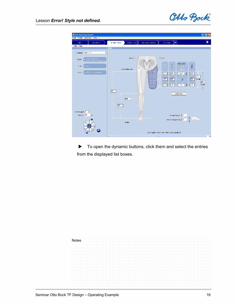
Entries in the Specification Tab
In the Specification tab, you enter the following information regarding
the socket and the patient:
Reference number of the job
Socket material
Liner
Valve
Mobility grade
Weight
Amputated side
Measurements of the amputated side
Residual limb length
Socket length
Three or five distance measurements, starting from the ischial
tuberosity
Three or five corresponding residual limb circumference
measurements
Reduction of the circumference measurements in % or mm

Lesson Error! Style not defined.
Seminar Otto Bock TF Design – Operating Example 15
Notes
If applicable, reduced socket circumference measurements as
direct entries
Measurements of the sound side
Ischial tuberosity to the floor
Medial tibial plateau to the floor
Largest calf circumference
Foot size (cm)
Effective heel height
Complete all fields and list boxes according to the example.
Lesson Error! Style not defined.
Seminar Otto Bock TF Design – Operating Example 16
Notes
To open the dynamic buttons, click them and select the entries
from the displayed list boxes.
Lesson Error! Style not defined.
Seminar Otto Bock TF Design – Operating Example 17
Notes
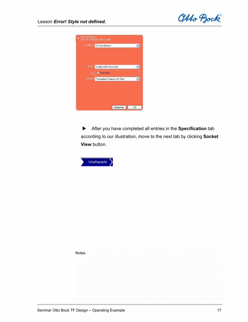
After you have completed all entries in the Specification tab
according to our illustration, move to the next tab by clicking Socket View button.

Lesson Error! Style not defined.
Seminar Otto Bock TF Design – Operating Example 18
Notes
Entries in the Socket View tab
In the Socket View tab, the generated socket is displayed in three
dimensions and can be viewed from all sides.
To do so, use the signpost and the tool bar.
Symbol Tools
Select
Rotate in three dimensions
Move
Zoom in
Zoom out
Original size (optimal display)
Lesson Error! Style not defined.
Seminar Otto Bock TF Design – Operating Example 19
Notes
In addition to the visualization functions, the following functions are
available to you to edit the socket:
Lateral brim adjustment
Perineum AP dimension
Bony ML dimension
Soft tissue ML Dimension
Angle of adduction
Angle of flexion
Distal shape
Lateral – posterior patch
Socket dimension display
You will see a dynamic button for each of these functions, which you
can show and hide using the triangle symbol.

Lesson Error! Style not defined.
Seminar Otto Bock TF Design – Operating Example 20
Notes
You open the individual buttons by clicking them; they contain:
A slide control to set the respective measurement
An Original Value button to return to the default setting
A button that displays the Ideal View for the respective
measurement
The respective measurement is shown as a red line on the socket in the
socket view. Changes to the measurements are also displayed on the
three-dimensional model.
Lesson Error! Style not defined.
Seminar Otto Bock TF Design – Operating Example 21
Notes
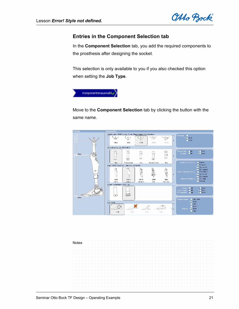
Entries in the Component Selection tab
In the Component Selection tab, you add the required components to
the prosthesis after designing the socket.
This selection is only available to you if you also checked this option
when setting the Job Type.
Move to the Component Selection tab by clicking the button with the
same name.
Lesson Error! Style not defined.
Seminar Otto Bock TF Design – Operating Example 22
Notes
You select the components from graphic lists in a five-step process.
Selection of the socket adapter
Selection of the upper component assembly
Selection of the knee joint
Selection of the lower component assembly
Selection of the foot
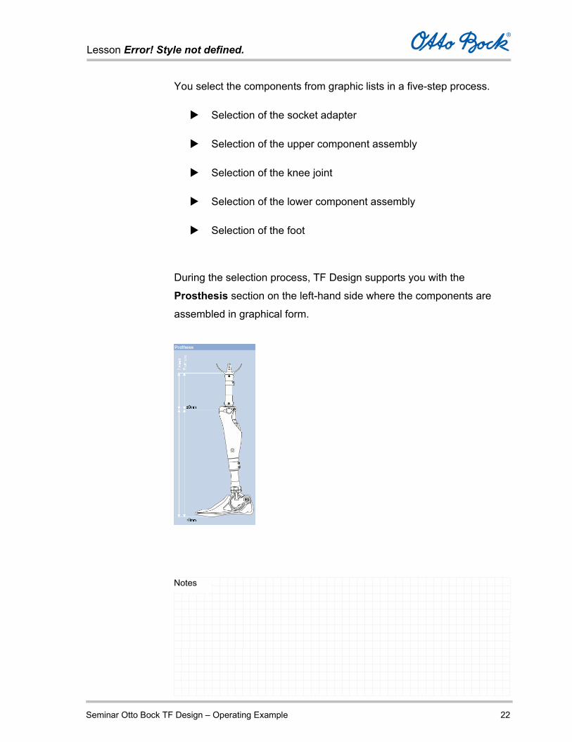
During the selection process, TF Design supports you with the
Prosthesis section on the left-hand side where the components are
assembled in graphical form.
Lesson Error! Style not defined.
Seminar Otto Bock TF Design – Operating Example 23
Notes
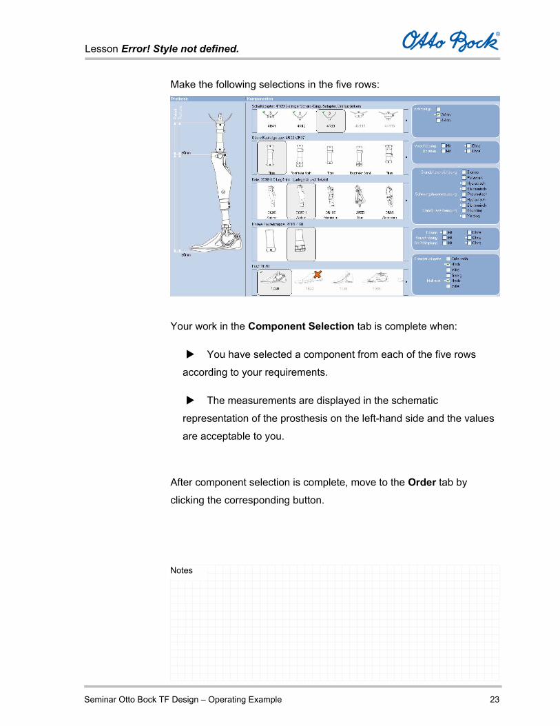
Make the following selections in the five rows:
Your work in the Component Selection tab is complete when:
You have selected a component from each of the five rows
according to your requirements.
The measurements are displayed in the schematic
representation of the prosthesis on the left-hand side and the values
are acceptable to you.
After component selection is complete, move to the Order tab by
clicking the corresponding button.

Lesson Error! Style not defined.
Seminar Otto Bock TF Design – Operating Example 24
Notes
Submitting the purchase order
After you are done processing the job in the TF Design
application, switch to the Purchase Order tab by clicking the
Purchase Order button.
Here you will see an order list of the configured components; you
can activate / deactivate the individual components by selecting
or deselecting the check box next to the component.
Components with a quantity of 0 are automatically deselected.
Lesson Error! Style not defined.
Seminar Otto Bock TF Design – Operating Example 25
Notes
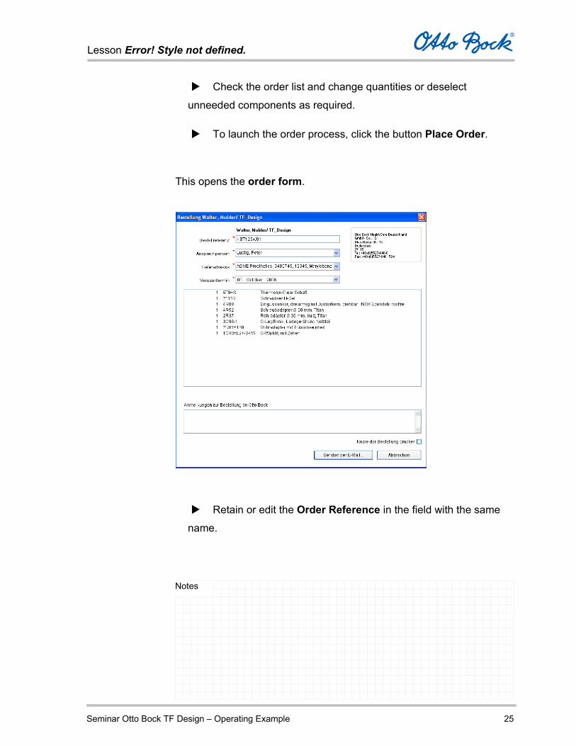
Check the order list and change quantities or deselect
unneeded components as required.
To launch the order process, click the button Place Order.
This opens the order form.
Retain or edit the Order Reference in the field with the same
name.

Lesson Error! Style not defined.
Seminar Otto Bock TF Design – Operating Example 26
Notes
If required, select a Contact Person in the field with the same
name.
Select a Shipping Address in the field with the same name.
The shipping address from the data of your medical supply company
is stored and always available for selection here.
Select a different Shipping Date or retain the date displayed.
If you also want to send your purchase order to the connected
printer, select the option Print Copy of Purchase Order.
Select Send by E-Mail. The purchase order data are
transferred to the e-mail program and can be sent out from there.
Attention You need to send out the e-mail with the purchase order data
yourself.

Lesson Error! Style not defined.
Seminar Otto Bock TF Design – Operating Example 27
Notes
Closing the Otto Bock Data Station
To close the Otto Bock Data Station, select the menu command File –
Exit or the symbol in the upper right corner of the program window.
If you have not yet saved the job data then the Otto Bock Data Station
will prompt you to do so. Therefore data cannot get lost.
The Otto Bock Data Station is closed and you are back at the Windows
XP desktop.
Lesson Error! Style not defined.
Seminar TF Design - Functions 1
Notes
Introduction
When working on jobs in the Otto Bock TF Design software, you go
through up to four program stages, each of which has a tab in the TF
Design processing window:
Specification
Selection of the socket-specific data and entry of the patient
measurements.
Socket View
Three-dimensional view of the calculated prosthesis socket, with the
option to make corrections.
Component Selection Selection of components for the prosthesis.
Ordering Display and editing of the purchase order for the current job.
Lesson Error! Style not defined.
Seminar TF Design - Functions 2
Notes
This is how you begin a Job in TF Design
Before you can create a transfemoral socket, you first have to
create the corresponding patient.
In the patient list of the Otto Bock Data Station, select the name
of the patient for whom you want to create a TF Design order.
Select the command New Job in the File menu, or use the New Job
button underneath the job list of the selected patient.
The Job Type tab is displayed. Select the dynamic button
Transfemoral.

Lesson Error! Style not defined.
Seminar TF Design - Functions 3
Notes
At this stage, you can already decide which program
components of TF Design you wish to use.
You always have several options available to you for this
purpose.
Select the corresponding option fields.
Lesson Error! Style not defined.
Seminar TF Design - Functions 4
Notes
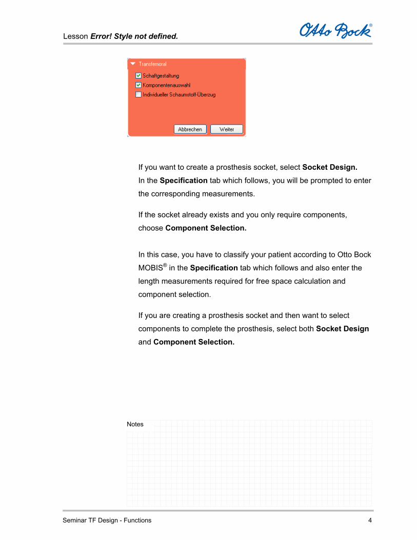
If you want to create a prosthesis socket, select Socket Design. In the Specification tab which follows, you will be prompted to enter
the corresponding measurements.
If the socket already exists and you only require components,
choose Component Selection.
In this case, you have to classify your patient according to Otto Bock
MOBIS® in the Specification tab which follows and also enter the
length measurements required for free space calculation and
component selection.
If you are creating a prosthesis socket and then want to select
components to complete the prosthesis, select both Socket Design and Component Selection.

Lesson Error! Style not defined.
Seminar TF Design - Functions 5
Notes
If you require a prosthesis socket, components, and an individual
foam cover, select all three options:
Socket Design, Component Selection, and
Custom cosmesis.
According to the selection, the measurements required for socket
design and component selection as well as additional circumference
measurements required for the custom cosmesis have to be entered
in the Specification tab that follows.
After you confirm your selection by clicking Next, the Specification tab
is opened in the TF Design processing window.
Enter all requested measurements here.
Lesson Error! Style not defined.
Seminar TF Design - Functions 6
Notes
Specification
In the Specification tab, the measurements and details required by the
software are entered corresponding to the options you selected in the
previous tab.
Thus the number of measurements required is determined by your
selections.
Provide the following information in the left-hand column of the tab:
Order number
Socket
Liner
Valve
Degree of mobility
Patient weight
The buttons are initially displayed in red, and change to blue as
soon as a selection has been made. The specifications under the
first button Socket are mandatory in order to continue, while the
information under the buttons Liner and Valve is optional and
only entered when required.

Lesson Error! Style not defined.
Seminar TF Design - Functions 7
Notes
Lesson Error! Style not defined.
Seminar TF Design - Functions 8
Notes
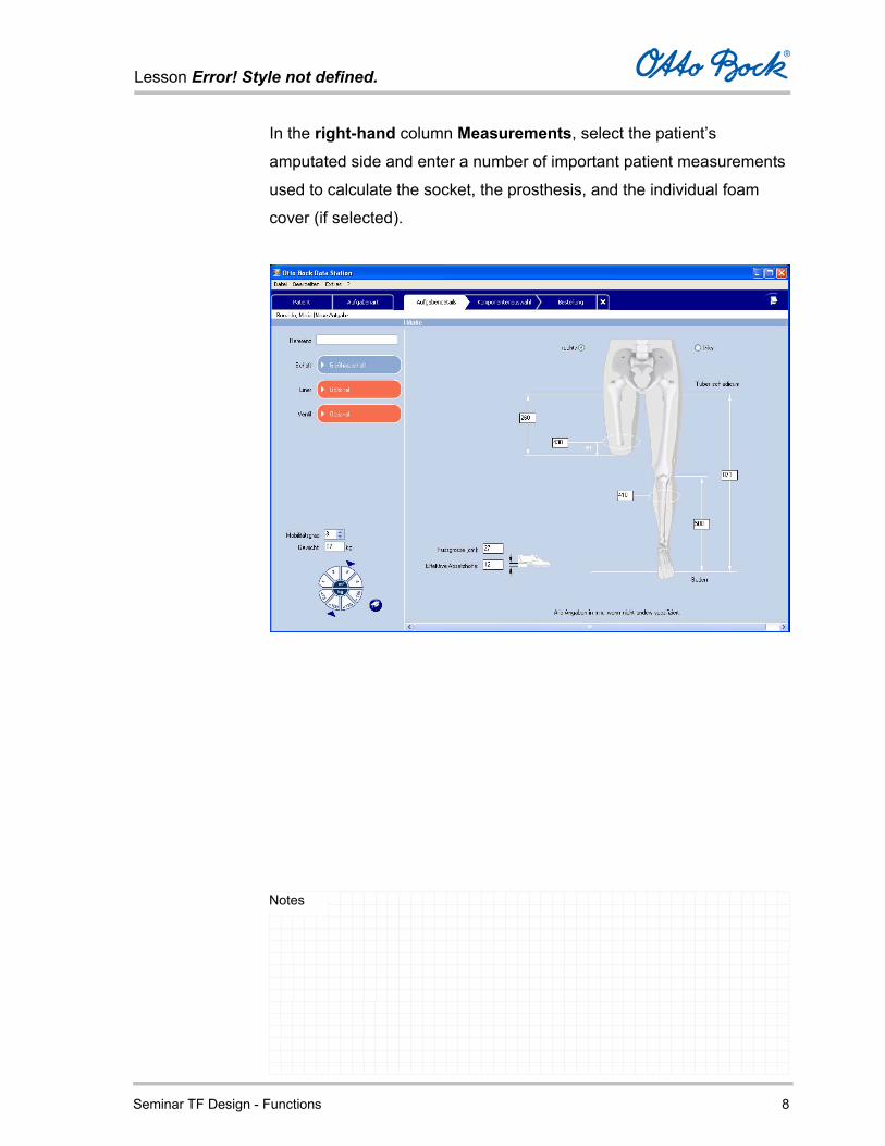
In the right-hand column Measurements, select the patient’s
amputated side and enter a number of important patient measurements
used to calculate the socket, the prosthesis, and the individual foam
cover (if selected).

Lesson Error! Style not defined.
Seminar TF Design - Functions 9
Notes
Entries in the Left-Hand Column
In the left-hand column, you pre-select a few core components of the
prosthesis socket. Thus you are influencing the design of the socket
and its 3D representation in the Socket View tab.
Furthermore, your patient can be classified here according to MOBIS®
(if Component Selection was chosen).
This determines which components from the Otto Bock product portfolio
are generally available for your patient in the component selection
process which follows, before the free space calculation is carried out.
Reference – identification of the current job.
Enter a reference or number for the job. This entry is later displayed
in the job list of the patient in order to identify the job data.
Provide additional information regarding the socket components
in the fields below.
Open and close these fields by clicking the corresponding
dynamic button.
Lesson Error! Style not defined.
Seminar TF Design - Functions 10
Notes
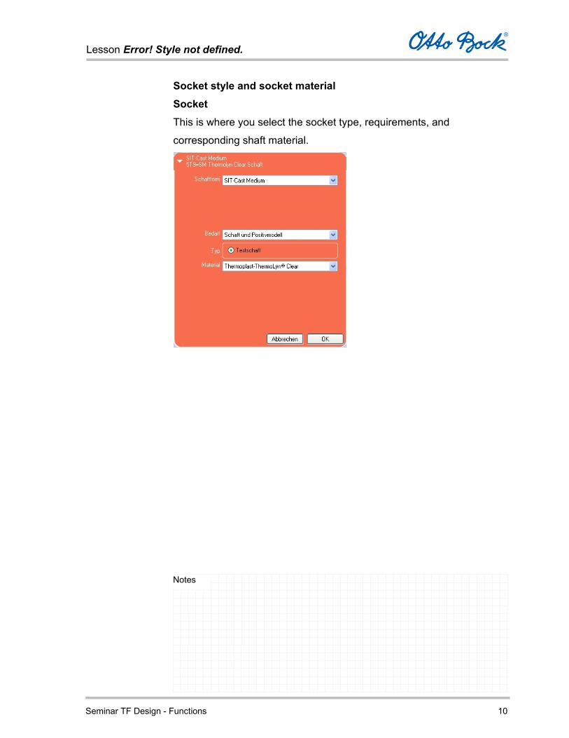
Socket style and socket material Socket This is where you select the socket type, requirements, and
corresponding shaft material.

Lesson Error! Style not defined.
Seminar TF Design - Functions 11
Notes
Liner If a liner is required, you can select the liner model, distal connection,
material, and liner size depending on the selected manufacturer.
Competitive products not included in the Otto Bock product
portfolio will not be considered on the order form.
Lesson Error! Style not defined.
Seminar TF Design - Functions 12
Notes
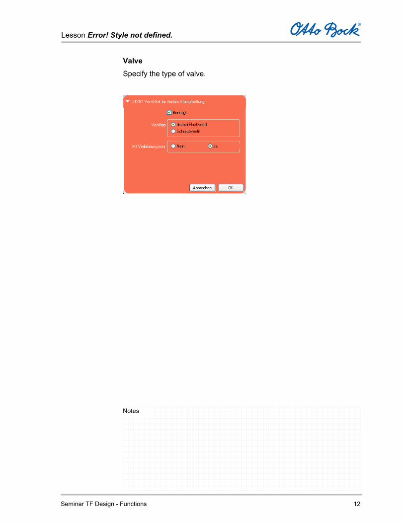
Valve Specify the type of valve.

Lesson Error! Style not defined.
Seminar TF Design - Functions 13
Notes
Mobility grade and weight
Mobility grade
Select the patient's mobility grade (grades 1 thru 4).
The selected mobility grade in conjunction with the patient weight has a
decisive influence on the functional characteristics of the prosthesis.
During the configuration of the prosthesis, only those components
which have structural and functional characteristics suitable for the
patient’s selected mobility gradeand weight will be displayed.
The mobility grades are defined as follows:
Mobility grade 1 – indoor walker
Mobility grade 2 – restricted outdoor walker
Mobility grade 3 – unrestricted outdoor walker
Mobility grade 4 – unrestricted outdoor walker with particularly high
demands
This classification corresponds to the generally applicable
profiling questionnaire of the Medizinischer Dienst der
Spitzenverbände der Krankenkassen e.V. (MDS) (German
Registered Association of Medical Services for the National
Lesson Error! Style not defined.
Seminar TF Design - Functions 14
Notes
Health Insurance Companies).
During processing, you receive information about the selected
mobility grade by clicking on the mortarboard symbol.
Weight
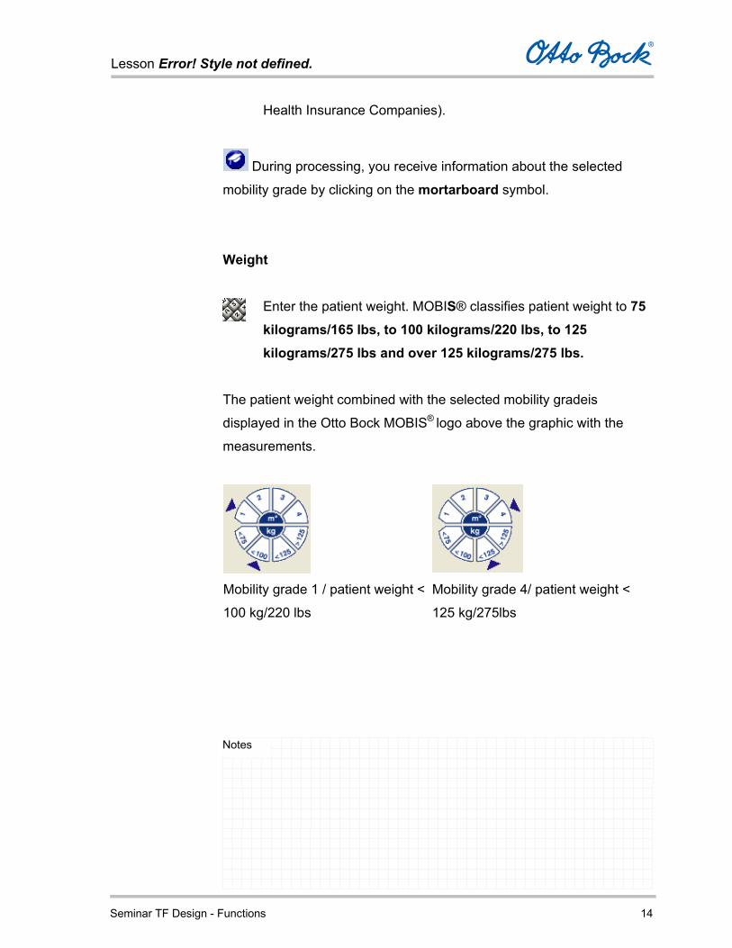
Enter the patient weight. MOBIS® classifies patient weight to 75 kilograms/165 lbs, to 100 kilograms/220 lbs, to 125 kilograms/275 lbs and over 125 kilograms/275 lbs.
The patient weight combined with the selected mobility gradeis
displayed in the Otto Bock MOBIS® logo above the graphic with the
measurements.
Mobility grade 1 / patient weight <
100 kg/220 lbs
Mobility grade 4/ patient weight <
125 kg/275lbs
Lesson Error! Style not defined.
Seminar TF Design - Functions 15
Notes
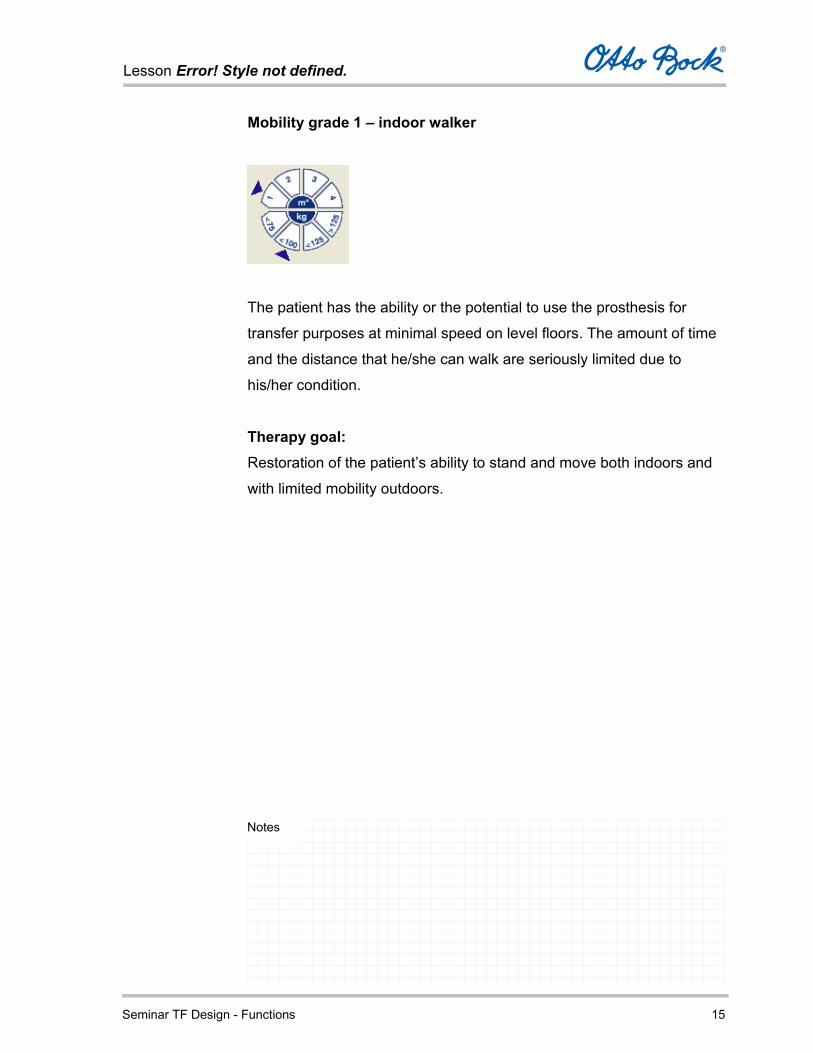
Mobility grade 1 – indoor walker
The patient has the ability or the potential to use the prosthesis for
transfer purposes at minimal speed on level floors. The amount of time
and the distance that he/she can walk are seriously limited due to
his/her condition.
Therapy goal: Restoration of the patient’s ability to stand and move both indoors and
with limited mobility outdoors.

Lesson Error! Style not defined.
Seminar TF Design - Functions 16
Notes
Mobility grade 2 – restricted outdoor walker
The patient has the ability or the potential to use the prosthesis for
transfer purposes at minimal speed on level floors. The amount of time
and the distance that he/she can walk are seriously limited due to
his/her condition.
Therapy goal: Restoration of the ability to stand, walk and move both indoors and
outdoors without any limitations.
Lesson Error! Style not defined.
Seminar TF Design - Functions 17
Notes
Mobility grade 3 – unrestricted outdoor walker
The patient has the ability or the potential to move with the prosthesis
with variable cadence and can simultaneously negotiate most
environmental barriers.
He/she also has the ability to move about open areas and can
undertake occupational, therapeutic and other activities that do not
expose the prosthesis to above-average mechanical demands.
This also includes those patients who have an increased need for
security due to secondary conditions (additional handicaps, special
living circumstances) in connection with medium to high mobility
activities. In comparison to healthy individuals, the amount of time and
the distance that he/she can walk are limited only in nonessential ways.
Therapy goal: Restoration of the ability to stand, walk and move both indoors and
outdoors without any limitations.
Lesson Error! Style not defined.
Seminar TF Design - Functions 18
Notes
Mobility grade 4 – unrestricted outdoor walker with particularly high demands
The patient has the ability to move with the prosthesis in a manner
similar to the unrestricted outdoor walker. The amount of time and the
distance that he/she can walk are not limited. Moreover, due to the high
functional demands, the prosthesis can sustain a high degree of shock,
tension and torsion.
Therapy goal: Restoration of the ability to stand, walk and move both indoors and
outdoors without any limitations.
Lesson Error! Style not defined.
Seminar TF Design - Functions 19
Notes
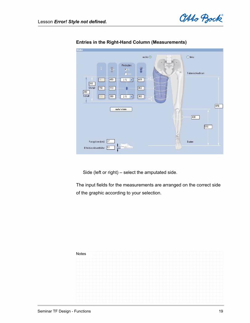
Entries in the Right-Hand Column (Measurements)
Side (left or right) – select the amputated side.
The input fields for the measurements are arranged on the correct side
of the graphic according to your selection.

Lesson Error! Style not defined.
Seminar TF Design - Functions 20
Notes
Measurements of the amputated side
Residual limb length – length of the residual limb from ischial
tuberosity to distal end.
Socket length –length of the socket from position of ischial tuberosity
to distal end.
Distance measurements, originating from the ischial tuberosity
By default, three distance measurements are displayed in order to
mark the height of the circumference measurements. The proximal
measurement is specified 30 mm distally from the ischial tuberosity.
The distal measurement is calculated as soon as the residual limb
length has been entered; it is 50 mm proximally from the end of the
residual limb.
Lesson Error! Style not defined.
Seminar TF Design - Functions 21
Notes
The position of the centre measurement can be freely selected and
should be positioned near the centre of the residual limb.
Limb circumference
Enter the measured residual limb circumferences at the respective
levels.
By clicking the More Values button, up to five circumference
measurements can be entered for the residual limb corresponding to
the distance measurements entered on the left.
If the Less Values button is selected, the standard setting with three
values is restored (30 mm below the ischial tuberosity, centre of the
residual limb, and 50 mm proximally from the end of the residual
limb).
Reduction of the circumference measurements in % or mm
Select the type of reduction for the respective circumference
measurements (percent or millimeters).
Each circumference measurement is reduced by either the selected
percentage (0-6) or the specified number of millimeters.
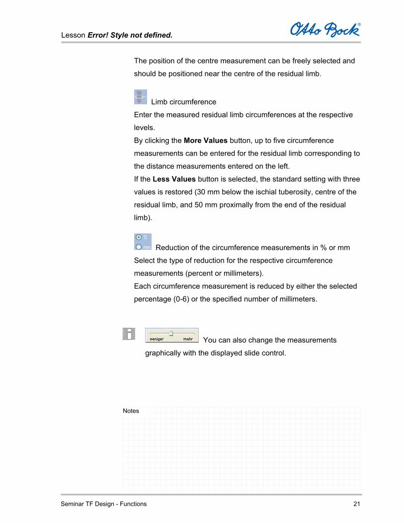
You can also change the measurements
graphically with the displayed slide control.
Lesson Error! Style not defined.
Seminar TF Design - Functions 22
Notes
Socket – circumference measurements
Displays or permits direct entry of the reduced circumference
measurements.
The effective remaining circumference measurements after the
corresponding reduction are displayed here.
The reduction can also be undertaken or modified directly by
entering the target measurements in this column.
Lesson Error! Style not defined.
Seminar TF Design - Functions 23
Notes
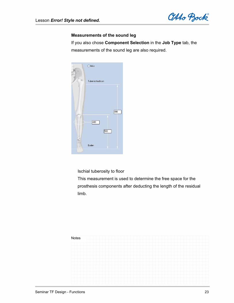
Measurements of the sound leg If you also chose Component Selection in the Job Type tab, the
measurements of the sound leg are also required.
Ischial tuberosity to floor
This measurement is used to determine the free space for the
prosthesis components after deducting the length of the residual
limb.
Lesson Error! Style not defined.
Seminar TF Design - Functions 24
Notes
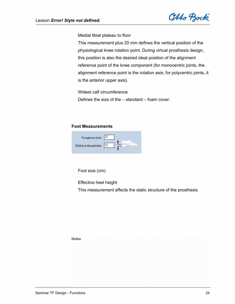
Medial tibial plateau to floor
This measurement plus 20 mm defines the vertical position of the
physiological knee rotation point. During virtual prosthesis design,
this position is also the desired ideal position of the alignment
reference point of the knee component (for monocentric joints, the
alignment reference point is the rotation axis; for polycentric joints, it
is the anterior upper axis).
Widest calf circumference
Defines the size of the – standard – foam cover.
Foot Measurements
Foot size (cm)
Effective heel height
This measurement affects the static structure of the prosthesis.
Lesson Error! Style not defined.
Seminar TF Design - Functions 25
Notes
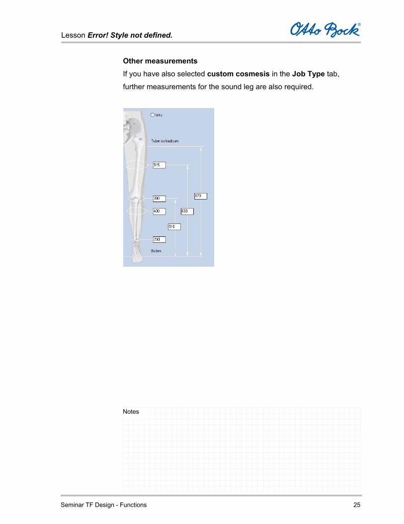
Other measurements If you have also selected custom cosmesis in the Job Type tab,
further measurements for the sound leg are also required.
Lesson Error! Style not defined.
Seminar TF Design - Functions 26
Notes
Methods for entering socket circumference
The socket circumferences can be determined and entered using three
different methods:
Method A: Reduction in percent or millimeters
Method B: Direct entry of the reduced measurements
Method C: Manual reduction of the circumference measurements
After completing the Specification tab, switch to the next tab Socket View by clicking it with the mouse.
Lesson Error! Style not defined.
Seminar TF Design - Functions 27
Notes
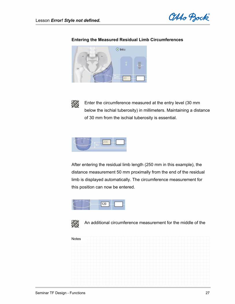
Entering the Measured Residual Limb Circumferences
Enter the circumference measured at the entry level (30 mm
below the ischial tuberosity) in millimeters. Maintaining a distance
of 30 mm from the ischial tuberosity is essential.
After entering the residual limb length (250 mm in this example), the
distance measurement 50 mm proximally from the end of the residual
limb is displayed automatically. The circumference measurement for
this position can now be entered.
An additional circumference measurement for the middle of the
Lesson Error! Style not defined.
Seminar TF Design - Functions 28
Notes
residual limb must be entered at the corresponding distance from
the ischial tuberosity.
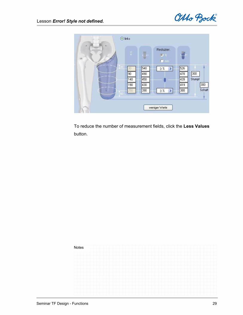
For very short residual limbs (90-120 mm) only the measurement
30 mm from the ischial tuberosity can be entered.
For very long residual limbs, it is also possible to enter additional
circumference measurements in the area between the initial
measurement (30 mm from the ischial tuberosity) and the end of
the residual limb (residual limb length - 50 mm).
You are free to choose the distances of the additional
circumference measurements from the ischial tuberosity, as long
as the distance between the measurements is at least 30 mm.
To do so, click the More Values button.
Two additional input fields for distance and circumference
measurements are displayed, so that a total of five circumference
measurements can be entered.
Lesson Error! Style not defined.
Seminar TF Design - Functions 29
Notes
To reduce the number of measurement fields, click the Less Values
button.

Lesson Error! Style not defined.
Seminar TF Design - Functions 30
Notes
Method A: Reduction in percent or millimeters
Determine the type of reduction in this column (percentage or
millimeters).
The corresponding reduction factor or value is selected and displayed in
the individual input fields.

Lesson Error! Style not defined.
Seminar TF Design - Functions 31
Notes
You can also change the measurements
graphically with the displayed slide control.
Even reduction profile
If the lock symbol is closed, the reduction profile from the proximal to
the distal end is even; that is, all circumference measurements are
reduced proportionally according to the selected reduction. This is
indicated by equal reduction values for the initial measurement and
the measurement 50 mm distally from the end of the residual limb.
Uneven reduction profile
In order to create an uneven reduction profile, click the lock symbol
which is then displayed as ‘opened’.
Now the reduction can be individually selected for the two
measurements mentioned above.
The reductions for the circumference measurements between the
initial measurement and the measurement 50 mm above the end
of the residual limb are calculated based on the selected
reductions, the level of the circumference measurements, and
the resulting elevation of the profile segments.

Lesson Error! Style not defined.
Seminar TF Design - Functions 32
Notes
Even reduction Uneven reduction
The socket circumference measurements calculated from the
residual limb measurements and reduction values are displayed in the
right-hand column.
Lesson Error! Style not defined.
Seminar TF Design - Functions 33
Notes
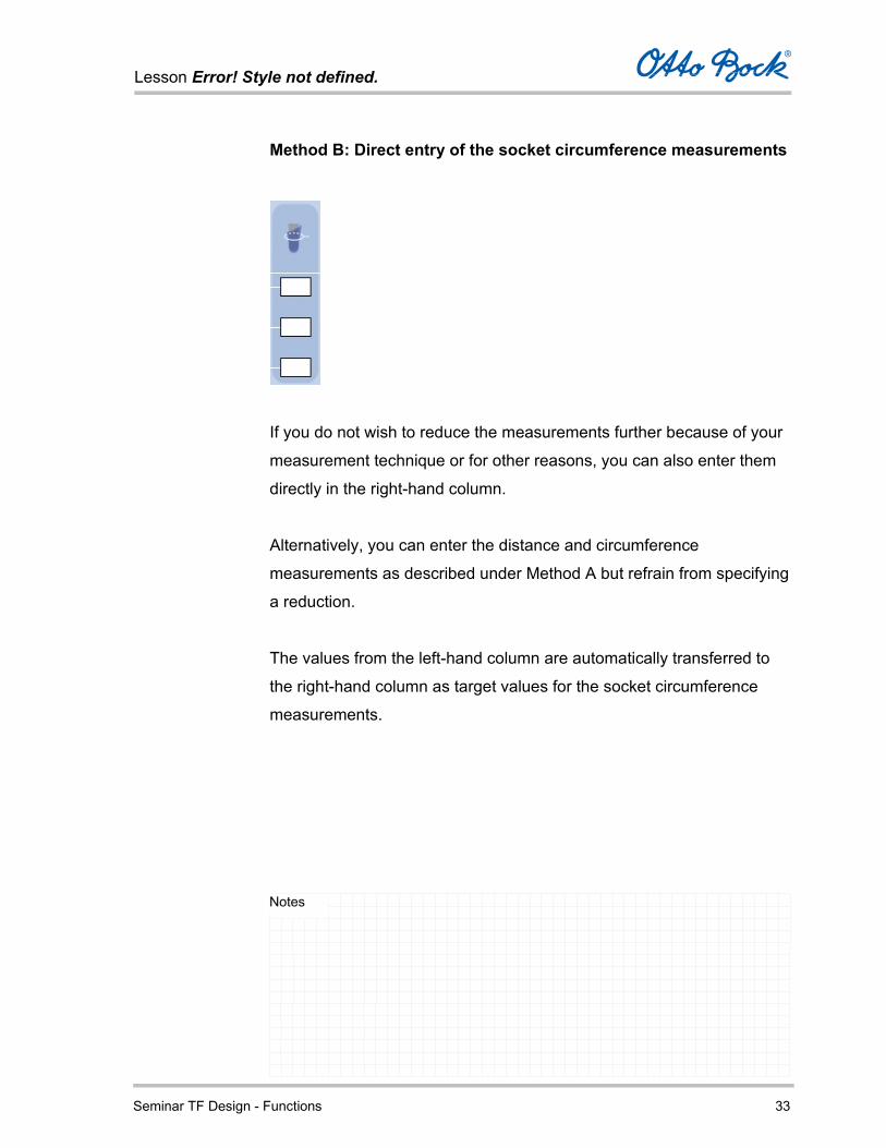
Method B: Direct entry of the socket circumference measurements
If you do not wish to reduce the measurements further because of your
measurement technique or for other reasons, you can also enter them
directly in the right-hand column.
Alternatively, you can enter the distance and circumference
measurements as described under Method A but refrain from specifying
a reduction.
The values from the left-hand column are automatically transferred to
the right-hand column as target values for the socket circumference
measurements.
Lesson Error! Style not defined.
Seminar TF Design - Functions 34
Notes
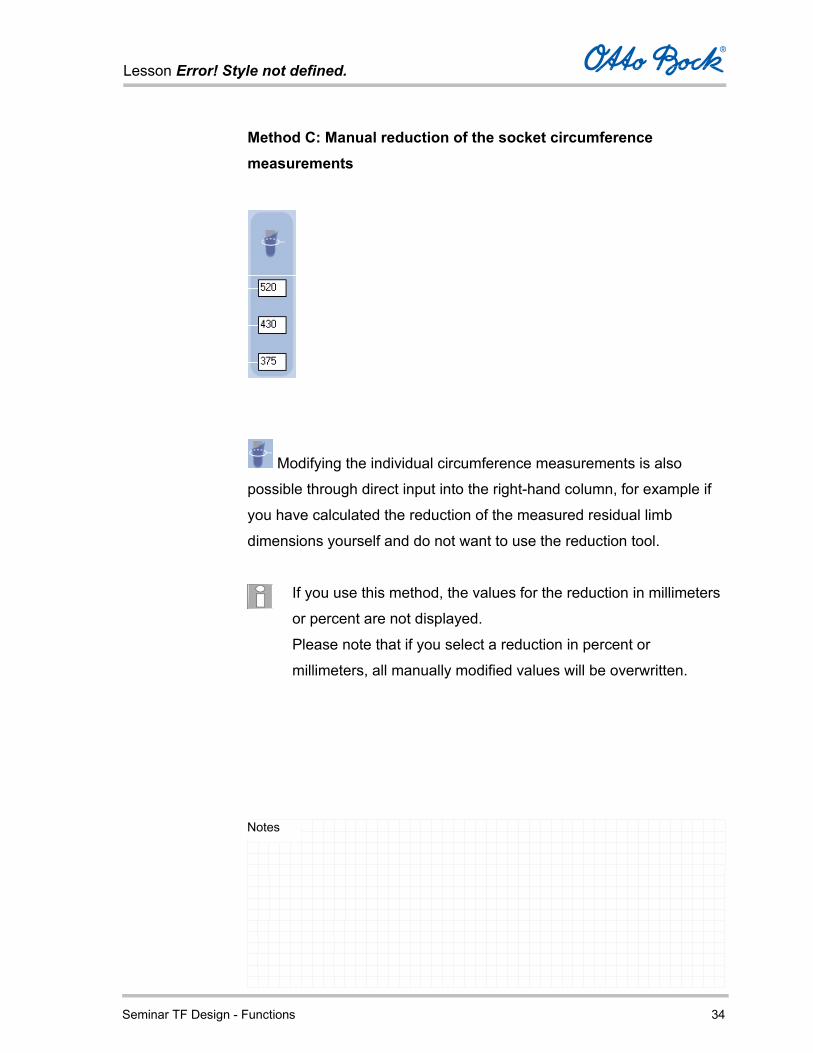
Method C: Manual reduction of the socket circumference measurements
Modifying the individual circumference measurements is also
possible through direct input into the right-hand column, for example if
you have calculated the reduction of the measured residual limb
dimensions yourself and do not want to use the reduction tool.
If you use this method, the values for the reduction in millimeters
or percent are not displayed.
Please note that if you select a reduction in percent or
millimeters, all manually modified values will be overwritten.

Lesson Error! Style not defined.
Seminar TF Design - Functions 35
Notes
Socket View
In the Socket View tab, the socket calculated based on the data you
have entered is displayed in three dimensions.
You can view the socket from all sides and rotate it freely in space by
dragging it with the mouse.
When you first open the Socket View tab, three-dimensional
rotation is activated by default.

Lesson Error! Style not defined.
Seminar TF Design - Functions 36
Notes
Symbolic Guide
Select the various socket views using the symbolic guide in the top right
corner of the screen.
You can modify the display size (zoom) of the socket by clicking the
right mouse button and dragging with the mouse.
Use this button in the top left corner of the screen to display or
hide the individual functions for editing the socket.

Lesson Error! Style not defined.
Seminar TF Design - Functions 37
Notes
Tools
Symbol Tools
Select
Three-dimensional rotation
Move
Zoom in
Zoom out
Original size (optimal display)

Lesson Error! Style not defined.
Seminar TF Design - Functions 38
Notes
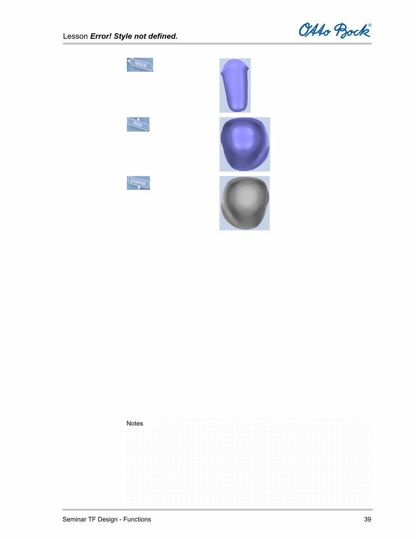
Views
Symbol View
Lesson Error! Style not defined.
Seminar TF Design - Functions 39
Notes
Lesson Error! Style not defined.
Seminar TF Design - Functions 40
Notes
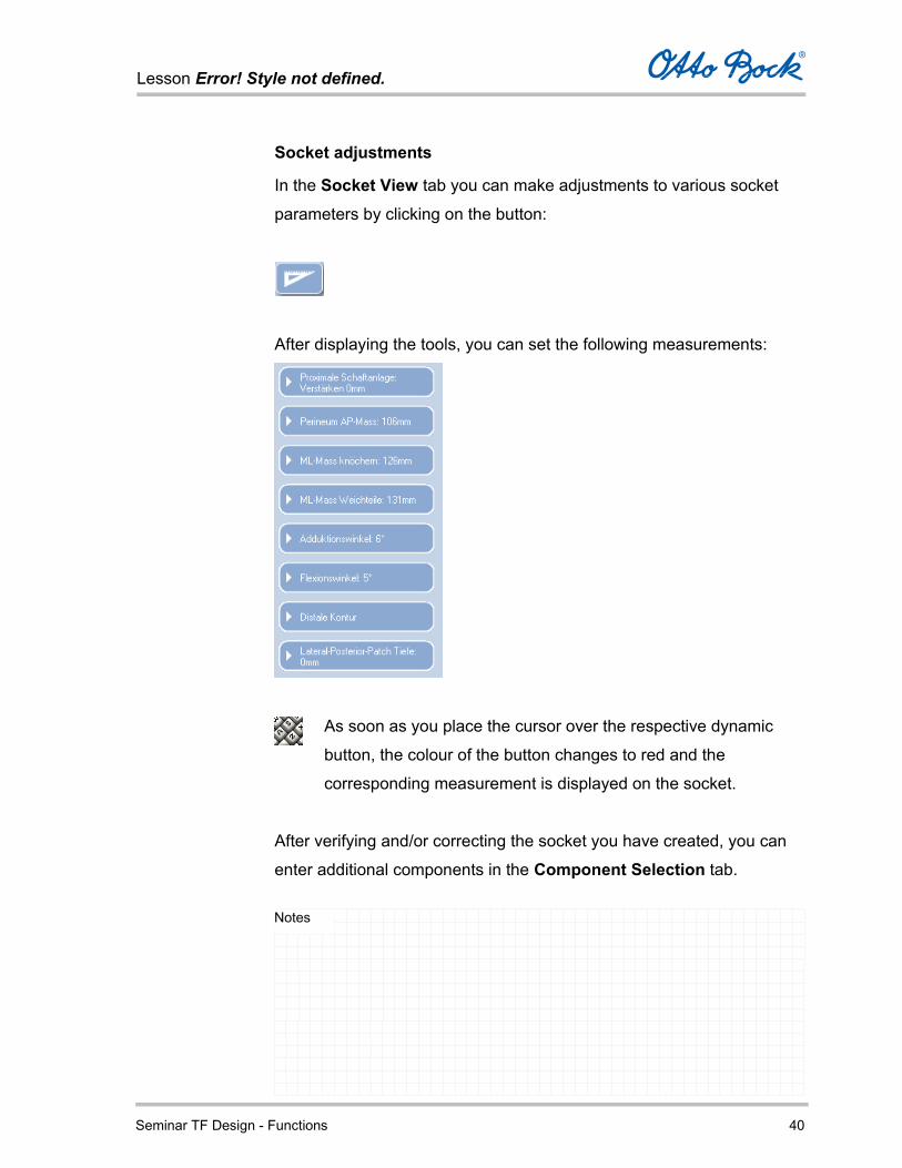
Socket adjustments
In the Socket View tab you can make adjustments to various socket
parameters by clicking on the button:
After displaying the tools, you can set the following measurements:
As soon as you place the cursor over the respective dynamic
button, the colour of the button changes to red and the
corresponding measurement is displayed on the socket.
After verifying and/or correcting the socket you have created, you can
enter additional components in the Component Selection tab.

Lesson Error! Style not defined.
Seminar TF Design - Functions 41
Notes
When you use the individual tools, the program either offers you
the best view via a button or automatically switches to the best
view during the adjustment.
This is the view that best displays the changes being made.

Lesson Error! Style not defined.
Seminar TF Design - Functions 42
Notes
Lateral brim adjustment
To edit the lateral brim adjustment, select the dynamic button
shown above. The current value in mm is displayed on the
button.
In addition to changing the value with a slide control, you can set the
socket view to posterior.
The changes to the dimensions are best displayed in this view.
Clicking on Original resets the adjustment to the original value.
Clicking on the top of the handle closes it.
Lesson Error! Style not defined.
Seminar TF Design - Functions 43
Notes
This function can be used to design the lateral brim adjustment
above the greater trochanter to be more or less pronounced.
Lesson Error! Style not defined.
Seminar TF Design - Functions 44
Notes
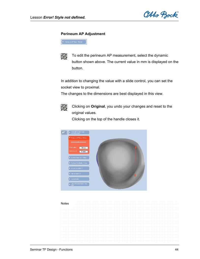
Perineum AP Adjustment
To edit the perineum AP measurement, select the dynamic
button shown above. The current value in mm is displayed on the
button.
In addition to changing the value with a slide control, you can set the
socket view to proximal.
The changes to the dimensions are best displayed in this view.
Clicking on Original, you undo your changes and reset to the
original values.
Clicking on the top of the handle closes it.
Lesson Error! Style not defined.
Seminar TF Design - Functions 45
Notes
The perineum AP measurement (red dimension line) enables you
to make the socket wider or narrower in the anterior-posterior
direction in the area of the perineum.
Note that by altering the perineum AP dimension, the initial
circumference value also changes.
Lesson Error! Style not defined.
Seminar TF Design - Functions 46
Notes
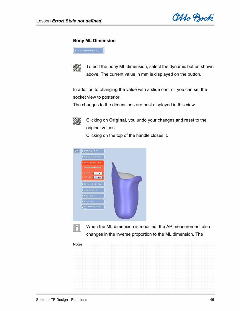
Bony ML Dimension
To edit the bony ML dimension, select the dynamic button shown
above. The current value in mm is displayed on the button.
In addition to changing the value with a slide control, you can set the
socket view to posterior.
The changes to the dimensions are best displayed in this view.
Clicking on Original, you undo your changes and reset to the
original values.
Clicking on the top of the handle closes it.
When the ML dimension is modified, the AP measurement also
changes in the inverse proportion to the ML dimension. The

Lesson Error! Style not defined.
Seminar TF Design - Functions 47
Notes
initial circumference measurement (30 mm below the ischial
tuberosity) is not modified.
Lesson Error! Style not defined.
Seminar TF Design - Functions 48
Notes
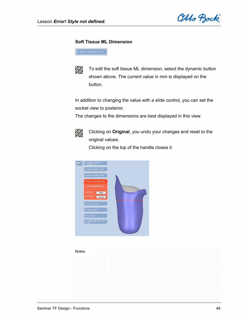
Soft Tissue ML Dimension
To edit the soft tissue ML dimension, select the dynamic button
shown above. The current value in mm is displayed on the
button.
In addition to changing the value with a slide control, you can set the
socket view to posterior.
The changes to the dimensions are best displayed in this view.
Clicking on Original, you undo your changes and reset to the
original values.
Clicking on the top of the handle closes it.
Lesson Error! Style not defined.
Seminar TF Design - Functions 49
Notes
The measurement field displays the calculated soft tissue ML dimension
according to your specifications.
The soft tissue ML dimension can only be changed in increments
of ±10 mm starting from the calculated value. The initial
circumference measurement (30 mm below the ischial tuberosity)
is not modified.
Lesson Error! Style not defined.
Seminar TF Design - Functions 50
Notes
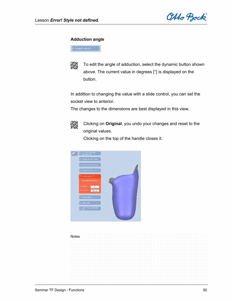
Adduction angle
To edit the angle of adduction, select the dynamic button shown
above. The current value in degrees [°] is displayed on the
button.
In addition to changing the value with a slide control, you can set the
socket view to anterior.
The changes to the dimensions are best displayed in this view.
Clicking on Original, you undo your changes and reset to the
original values.
Clicking on the top of the handle closes it.
Lesson Error! Style not defined.
Seminar TF Design - Functions 51
Notes
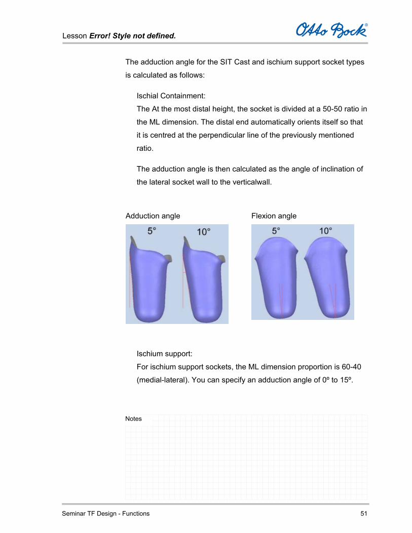
The adduction angle for the SIT Cast and ischium support socket types
is calculated as follows:
Ischial Containment:
The At the most distal height, the socket is divided at a 50-50 ratio in
the ML dimension. The distal end automatically orients itself so that
it is centred at the perpendicular line of the previously mentioned
ratio.
The adduction angle is then calculated as the angle of inclination of
the lateral socket wall to the verticalwall.
Adduction angle Flexion angle
Ischium support:
For ischium support sockets, the ML dimension proportion is 60-40
(medial-lateral). You can specify an adduction angle of 0º to 15º.
Lesson Error! Style not defined.
Seminar TF Design - Functions 52
Notes
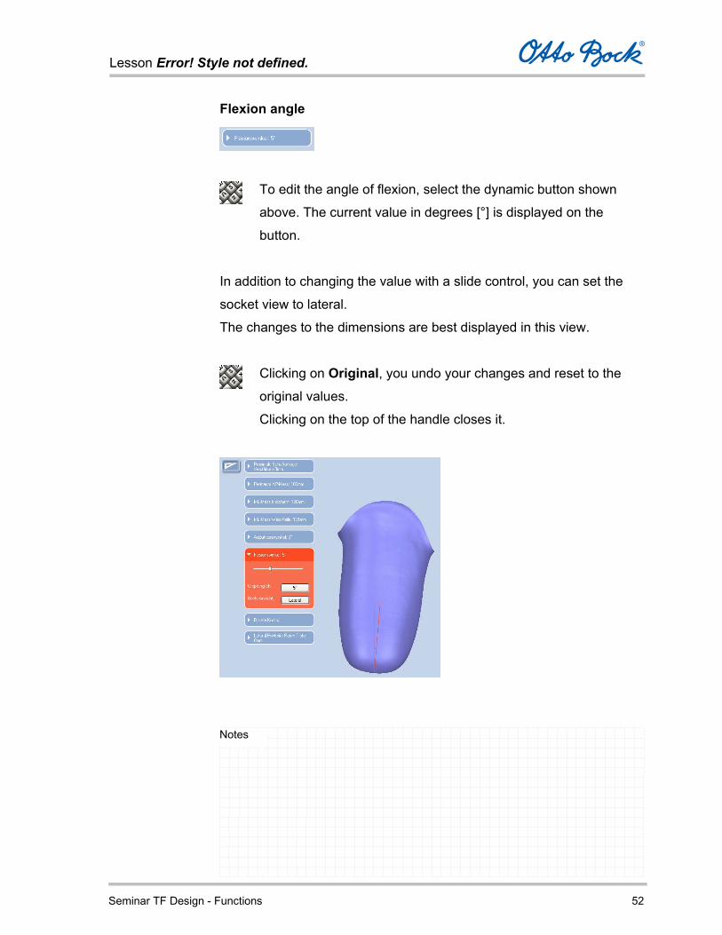
Flexion angle
To edit the angle of flexion, select the dynamic button shown
above. The current value in degrees [°] is displayed on the
button.
In addition to changing the value with a slide control, you can set the
socket view to lateral.
The changes to the dimensions are best displayed in this view.
Clicking on Original, you undo your changes and reset to the
original values.
Clicking on the top of the handle closes it.

Lesson Error! Style not defined.
Seminar TF Design - Functions 53
Notes
The sockets are designed with a default flexion angle of 5º. If no
other flexion angle is entered, the socket will be supplied with
this default.
You can specify a flexion angle of 0º to 15º.
The flexion angle is measured from the centre of the vertical
socket plumb line to the corresponding socket position.

Lesson Error! Style not defined.
Seminar TF Design - Functions 54
Notes
Distal Contour
To adjust the distal shape, click on the handle shown above. The
default setting places the slider in the centre between ‘pointed’
and ‘flat’ shapes. The slider can be moved change the distal
shape accordingly. The socket length is not affected in this
process.
In addition to changing the shape using the slider control, you can set
the socket view into an anterior orientation.
In this best view, the adjustment is most clearly seen.
Clicking on Original, you undo your changes and reset to the
original values.
Clicking on the top of the handle closes it.

Lesson Error! Style not defined.
Seminar TF Design - Functions 55
Notes
Lateral – Posterior Patch
To adjust the patch depth of the lateral channel, click on the
handle shown above. The currently set value in mm is shown on
the handle.
In addition to changing the shape using the slider control, you can set
the socket view into a posterior orientation.
Clicking on Original, you undo your changes and reset to the
original values.
Clicking on the top of the handle closes it.

Lesson Error! Style not defined.
Seminar TF Design - Functions 56
Notes
Display of socket dimensions
If you move the mouse cursor over the socket, an information field is
shown in the bottom right-hand corner of the screen. Here, the socket
dimensions are shown in at the respective cursor position.
Moving the cursor over the socket allows you to obtain the following
dimensions for the respective cursor position:
Distance to the ischial tuberosity (Z)
ML dimension
AP dimension
Socket circumference
Socket volume
Lesson Error! Style not defined.
Seminar TF Design - Functions 57
Notes
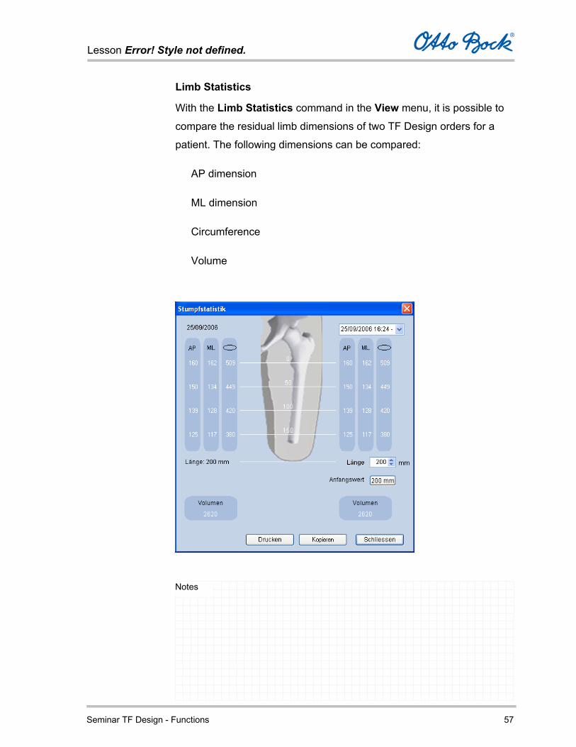
Limb Statistics
With the Limb Statistics command in the View menu, it is possible to
compare the residual limb dimensions of two TF Design orders for a
patient. The following dimensions can be compared:
AP dimension
ML dimension
Circumference
Volume
Lesson Error! Style not defined.
Seminar TF Design - Functions 58
Notes
After opening the residual limb statistics window, the left-hand side of
the window initially displays the values for the current job.
To compare these values with another job for the same patient,
you can select another job by date or reference in the selection
field at the top right.
The values for the comparative job are then displayed on the right-hand
side of the window.
Equalising the socket length
Prior to comparing two sets of measurements, it is necessary to
equalise the measured lengths to the same value so that a realistic
comparison is possible.
Differing length measurements result from unavoidable
measurement error in obtaining patient measurements.
Using a manual control it is possible to compare the volumes of
the two sets of measurements with comparable length.
Lesson Error! Style not defined.
Seminar TF Design - Functions 59
Notes
Read the corresponding length of the residual limb from the
current values on the left-hand side and enter the same value in
the Length field on the right-hand side. The button Original Value located below displays the original residual limb length of
the second job and resets it when the button is clicked.
In the two Volume areas, you can compare the volumes of the two sets
of measurements.
Print outputs the data of the limb statistics to the connected standard
Windows printer.
Copy saves the data of the limb statistics to the Windows
clipboard. Use Ctrl+V to enter the data into another program,
such as a text processor, for further use.
Lesson Error! Style not defined.
Seminar TF Design - Functions 60
Notes
Component Selection
In the Component Selection tab, TF Design guides you through all
phases of functional and constructive prosthesis configuration.
Since the initial calculation of the possible component combinations
demands a lot of computer processing power, you can monitor the
progress of this activity on the blue progress bar in the top of the
component selection tab.
The individual prosthesis components are then displayed for selection
based on the specified mobility grade and patient weight and the related
characteristics and criteria.
This configurator guides you through the component selection and
assembly process step by step, and continuously informs you about all
available options and the characteristics of the individual components.

Lesson Error! Style not defined.
Seminar TF Design - Functions 61
Notes
The functions in the Component Selection tab are only
available if you chose the Component Selection option in the
Job Type tab.
After component selection is complete, you move to the Order tab.
Lesson Error! Style not defined.
Seminar TF Design - Functions 62
Notes
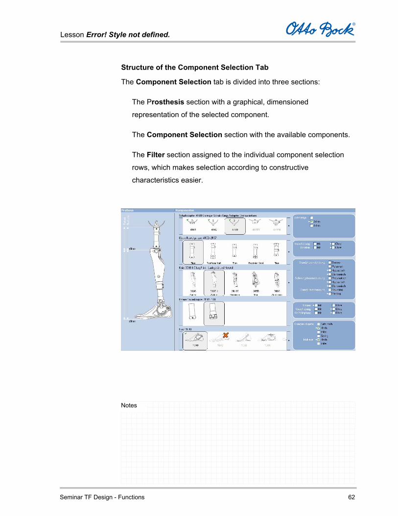
Structure of the Component Selection Tab
The Component Selection tab is divided into three sections:
The Prosthesis section with a graphical, dimensioned
representation of the selected component.
The Component Selection section with the available components.
The Filter section assigned to the individual component selection
rows, which makes selection according to constructive
characteristics easier.
Lesson Error! Style not defined.
Seminar TF Design - Functions 63
Notes
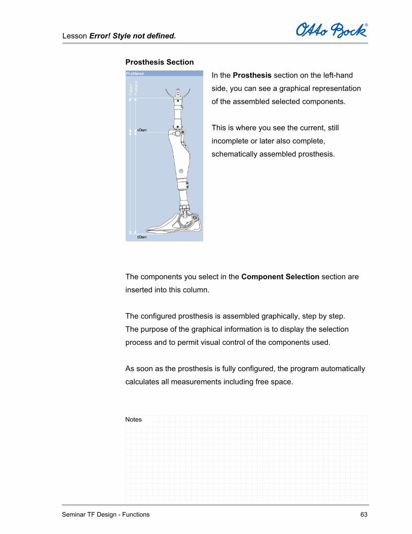
Prosthesis Section
In the Prosthesis section on the left-hand
side, you can see a graphical representation
of the assembled selected components.
This is where you see the current, still
incomplete or later also complete,
schematically assembled prosthesis.
The components you select in the Component Selection section are
inserted into this column.
The configured prosthesis is assembled graphically, step by step.
The purpose of the graphical information is to display the selection
process and to permit visual control of the components used.
As soon as the prosthesis is fully configured, the program automatically
calculates all measurements including free space.
Lesson Error! Style not defined.
Seminar TF Design - Functions 64
Notes
The lower dimension of ± 0 shows that the selected
components fit into the available free space and that an
adjustment to the required overall prosthesis length is possible.
The upper value provides information regarding the position of
the alignment reference point (for monocentric joints, the
alignment reference point is the rotation axis; for polycentric
joints, it is the anterior upper axis).
The ideal position of the alignment reference point is assumed to
be 20 mm above the medial tibial plateau of the sound leg.
This is the case as soon as the upper value is ± 0 mm.
If the upper value deviates in the negative range, the alignment
reference point is too high up and vice versa.

Lesson Error! Style not defined.
Seminar TF Design - Functions 65
Notes
Component Selection Section
In the Component Selection section in the centre, you select
the individual components - which are displayed graphically -
simply by clicking the illustration of the desired component.
Lesson Error! Style not defined.
Seminar TF Design - Functions 66
Notes
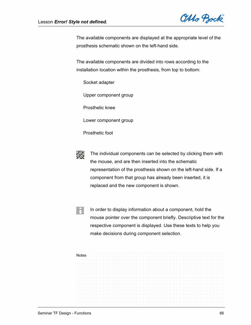
The available components are displayed at the appropriate level of the
prosthesis schematic shown on the left-hand side.
The available components are divided into rows according to the
installation location within the prosthesis, from top to bottom:
Socket adapter
Upper component group
Prosthetic knee
Lower component group
Prosthetic foot
The individual components can be selected by clicking them with
the mouse, and are then inserted into the schematic
representation of the prosthesis shown on the left-hand side. If a
component from that group has already been inserted, it is
replaced and the new component is shown.
In order to display information about a component, hold the
mouse pointer over the component briefly. Descriptive text for the
respective component is displayed. Use these texts to help you
make decisions during component selection.
Lesson Error! Style not defined.
Seminar TF Design - Functions 67
Notes
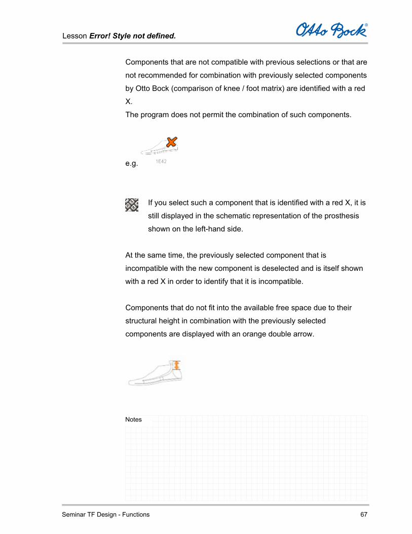
Components that are not compatible with previous selections or that are
not recommended for combination with previously selected components
by Otto Bock (comparison of knee / foot matrix) are identified with a red
X.
The program does not permit the combination of such components.
e.g.
If you select such a component that is identified with a red X, it is
still displayed in the schematic representation of the prosthesis
shown on the left-hand side.
At the same time, the previously selected component that is
incompatible with the new component is deselected and is itself shown
with a red X in order to identify that it is incompatible.
Components that do not fit into the available free space due to their
structural height in combination with the previously selected
components are displayed with an orange double arrow.
Lesson Error! Style not defined.
Seminar TF Design - Functions 68
Notes
If you select such a component that is identified with an orange
double arrow, it is still displayed in the schematic representation
of the prosthesis shown on the left-hand side.
At the same time, the previously selected component that requires too
much space in combination with the new component is deselected and
is itself shown with an orange double arrow in order to identify the
space issue.
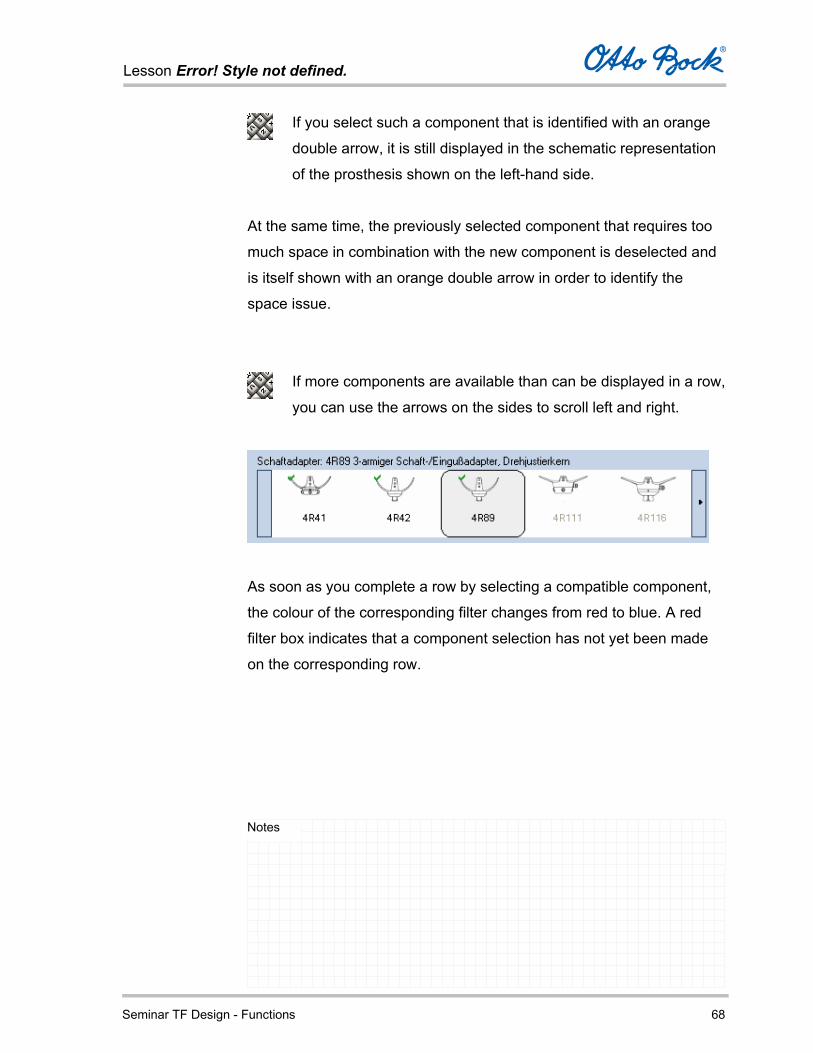
If more components are available than can be displayed in a row,
you can use the arrows on the sides to scroll left and right.
As soon as you complete a row by selecting a compatible component,
the colour of the corresponding filter changes from red to blue. A red
filter box indicates that a component selection has not yet been made
on the corresponding row.
Lesson Error! Style not defined.
Seminar TF Design - Functions 69
Notes
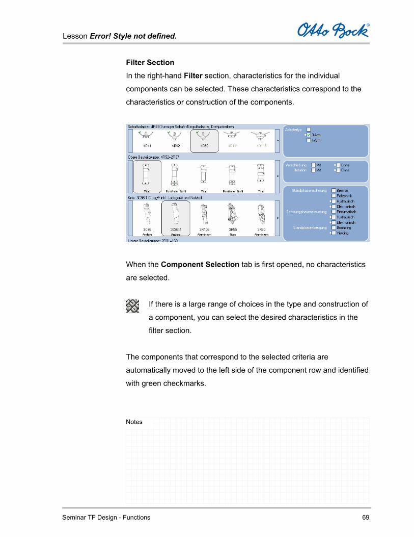
Filter Section In the right-hand Filter section, characteristics for the individual
components can be selected. These characteristics correspond to the
characteristics or construction of the components.
When the Component Selection tab is first opened, no characteristics
are selected.
If there is a large range of choices in the type and construction of
a component, you can select the desired characteristics in the
filter section.
The components that correspond to the selected criteria are
automatically moved to the left side of the component row and identified
with green checkmarks.
Lesson Error! Style not defined.
Seminar TF Design - Functions 70
Notes
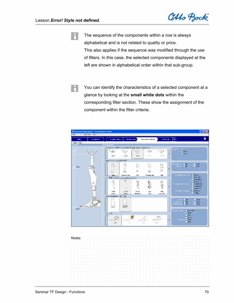
The sequence of the components within a row is always
alphabetical and is not related to quality or price.
This also applies if the sequence was modified through the use
of filters. In this case, the selected components displayed at the
left are shown in alphabetical order within that sub-group.
You can identify the characteristics of a selected component at a
glance by looking at the small white dots within the
corresponding filter section. These show the assignment of the
component within the filter criteria.

Lesson Error! Style not defined.
Seminar TF Design - Functions 71
Notes
Your work in the Component Selection tab is complete when:
You have selected a component from each of the five rows
according to your requirements.
The measurements are displayed in the schematic representation of
the prosthesis on the left-hand side and the values are acceptable to
you.
After component selection is complete, move to the Order tab by
clicking the corresponding button.
Ordering
In the Order tab, you can view a summary of the configured order as
well as summarized and detailed lists of all components.
Lesson Error! Style not defined.
Seminar TF Design - Functions 72
Notes
Lesson Error! Style not defined.
Seminar TF Design - Functions 73
Notes
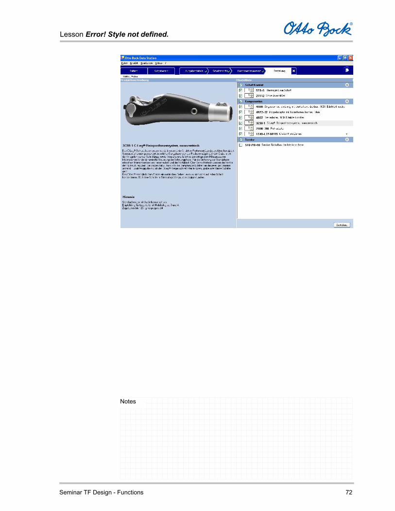
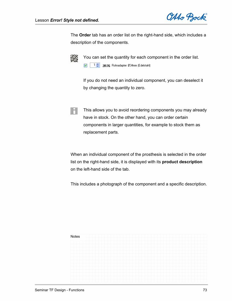
The Order tab has an order list on the right-hand side, which includes a
description of the components.
You can set the quantity for each component in the order list.
If you do not need an individual component, you can deselect it
by changing the quantity to zero.
This allows you to avoid reordering components you may already
have in stock. On the other hand, you can order certain
components in larger quantities, for example to stock them as
replacement parts.
When an individual component of the prosthesis is selected in the order
list on the right-hand side, it is displayed with its product description
on the left-hand side of the tab.
This includes a photograph of the component and a specific description.
Lesson Error! Style not defined.
Seminar TF Design - Functions 74
Notes
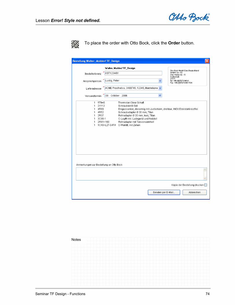
To place the order with Otto Bock, click the Order button.
Lesson Error! Style not defined.
Seminar TF Design - Functions 75
Notes
This opens the Order form, where you can complete the following
information:
Order reference
Enter an order reference. By default, the field displays the order
reference entered at the outset.
Contact person
You can select a contact person here.
The data for the list of contact persons can be maintained in the tab
Addresses/Personnel of the option dialog (menu command Tools – Options…).
Shipping address
You can select an alternative shipping address here.
The data for the list of shipping addresses can be maintained in the
Addresses/ Personnel tab (menu command Tools – Options).
Selection of the shipping date (depends on regional settings). With
the help of the calendar, you can select the desired shipping date.
No partial delivery – depends on regional settings. If you check this
field, the order will only be sent as a complete delivery. The order
will not be sent until all parts are available.
Notes to Otto Bock regarding the order
You can enter order notes here.

Lesson Error! Style not defined.
Seminar TF Design - Functions 76
Notes
Please note that deviations from the scope and content of the
order are not considered here.
Send by e-mail …
E-mail the order to Otto Bock.
Depending on the e-mail configuration settings, the e-mail program
is opened and ready to send the order.
Alternatively, if you have a non-MAPI e-mail application, you receive
a message that the order file has been generated successfully. The
corresponding folder, file name, e-mail address, and subject line are
also displayed.
You then have to send the order file to Otto Bock manually as an
attachment to an e-mail.
Please do not forget to copy the subject line into the e-mail message
before you send it.

Lesson Error! Style not defined.
Seminar TF Design - Functions 77
Notes
If you check this field, a copy of the order is automatically sent to the
default Windows printer when the order is placed.
Cancel
Cancels the order process.