ossie 0.8.2 user guide
TRANSCRIPT
OSSIE 0.8.2 Installation and User Guide
Matt Carrick, Drew Cormier, Christopher Covington, Carl B. Dietrich,Joseph Gaeddert, Benjamin Hilburn, C. Ian Phelps, Shereef Sayed,Deepan Seeralan, Jason Snyder, Haris Volos
April, 2011
OSSIE is an open source Software Defined Radio (SDR) development effort based at VirginiaTech. OSSIE is primarily intended to enable research and education in SDR and wireless com-munications. The software package includes an SDR core framework based on the JTRS SoftwareCommunications Architecture, tools for rapid development of SDR components and waveforms(applications), and an evolving library of pre-built components and waveforms. In addition, freelaboratory exercises for SDR education and training are being developed in cooperation with theNaval Postgraduate School.
OSSIE is the Open Source SCA Implementation::Embedded
Contents
1 Quick Start Guide 1
1.1 Using the OSSIE VMware Player Image . . . . . . . . . . . . . . . . . . . . . . . . . 1
1.2 Running the OSSIE Demonstration Waveform . . . . . . . . . . . . . . . . . . . . . . 1
2 Introduction 5
2.1 About this Guide . . . . . . . . . . . . . . . . . . . . . . . . . . . . . . . . . . . . . . 5
2.2 Further Help . . . . . . . . . . . . . . . . . . . . . . . . . . . . . . . . . . . . . . . . 5
2.2.1 Wiki . . . . . . . . . . . . . . . . . . . . . . . . . . . . . . . . . . . . . . . . . 5
2.2.2 Mailing Lists . . . . . . . . . . . . . . . . . . . . . . . . . . . . . . . . . . . . 5
2.2.3 Trac Bug Tracking System . . . . . . . . . . . . . . . . . . . . . . . . . . . . 6
2.2.4 The #ossie IRC Channel . . . . . . . . . . . . . . . . . . . . . . . . . . . . . 6
3 Installation 7
3.1 Installing OSSIE from Source . . . . . . . . . . . . . . . . . . . . . . . . . . . . . . . 7
3.1.1 Notes on OSSIE Installation from Source . . . . . . . . . . . . . . . . . . . . 7
3.1.2 Installing Dependencies on Fedora . . . . . . . . . . . . . . . . . . . . . . . . 7
3.1.3 Installing Dependencies on Ubuntu . . . . . . . . . . . . . . . . . . . . . . . . 8
3.1.4 Configure omniORB . . . . . . . . . . . . . . . . . . . . . . . . . . . . . . . . 9
3.1.5 Installing Portions of GNU Radio . . . . . . . . . . . . . . . . . . . . . . . . . 9
3.1.6 Install OSSIE . . . . . . . . . . . . . . . . . . . . . . . . . . . . . . . . . . . . 11
3.1.7 Using Autoconf . . . . . . . . . . . . . . . . . . . . . . . . . . . . . . . . . . . 11
3.1.8 Updating System Libraries . . . . . . . . . . . . . . . . . . . . . . . . . . . . 12
3.2 Installation of OSSIE Eclipse Feature . . . . . . . . . . . . . . . . . . . . . . . . . . . 12
3.2.1 Installing Java . . . . . . . . . . . . . . . . . . . . . . . . . . . . . . . . . . . 12
3.2.2 Installing Java on Older Versions of Fedora . . . . . . . . . . . . . . . . . . . 12
3.2.3 Installing Java on Ubuntu . . . . . . . . . . . . . . . . . . . . . . . . . . . . . 13
3.2.4 Installing Eclipse . . . . . . . . . . . . . . . . . . . . . . . . . . . . . . . . . . 13
3.2.5 Installing OEF . . . . . . . . . . . . . . . . . . . . . . . . . . . . . . . . . . . 13
ii
3.3 Using a VMware Image on Any Platform . . . . . . . . . . . . . . . . . . . . . . . . 14
4 Running Waveforms 15
4.1 Starting the CORBA Naming Service . . . . . . . . . . . . . . . . . . . . . . . . . . 15
4.2 Running nodeBooter . . . . . . . . . . . . . . . . . . . . . . . . . . . . . . . . . . . . 15
4.3 Nodebooter Clean-Up . . . . . . . . . . . . . . . . . . . . . . . . . . . . . . . . . . . 15
4.4 Loading a Waveform . . . . . . . . . . . . . . . . . . . . . . . . . . . . . . . . . . . . 16
5 Waveform Workshop 18
5.1 OSSIE Eclipse Feature . . . . . . . . . . . . . . . . . . . . . . . . . . . . . . . . . . . 18
5.2 OSSIE Waveform Developer . . . . . . . . . . . . . . . . . . . . . . . . . . . . . . . . 18
5.3 ALF Graphical Debugging . . . . . . . . . . . . . . . . . . . . . . . . . . . . . . . . . 19
5.4 WaveDash . . . . . . . . . . . . . . . . . . . . . . . . . . . . . . . . . . . . . . . . . . 19
6 OSSIE Eclipse Feature 22
6.1 Creating a New Waveform from Existing Components . . . . . . . . . . . . . . . . . 22
6.1.1 Adding Components to the Waveform . . . . . . . . . . . . . . . . . . . . . . 23
6.1.2 Connecting Components . . . . . . . . . . . . . . . . . . . . . . . . . . . . . . 25
6.1.3 Setting the Assembly Controller . . . . . . . . . . . . . . . . . . . . . . . . . 25
6.1.4 Editing Component Properties . . . . . . . . . . . . . . . . . . . . . . . . . . 25
6.1.5 Deploying Components to a Node . . . . . . . . . . . . . . . . . . . . . . . . 26
6.2 Creating a New Component . . . . . . . . . . . . . . . . . . . . . . . . . . . . . . . . 26
6.2.1 Adding Ports to the Component . . . . . . . . . . . . . . . . . . . . . . . . . 27
6.2.2 Adding Properties to the Component . . . . . . . . . . . . . . . . . . . . . . 30
6.2.3 Generating the Source Code . . . . . . . . . . . . . . . . . . . . . . . . . . . . 32
6.2.4 Editing C++ Components . . . . . . . . . . . . . . . . . . . . . . . . . . . . . 33
6.2.5 Editing Python Components . . . . . . . . . . . . . . . . . . . . . . . . . . . 33
6.2.6 Installing a Component . . . . . . . . . . . . . . . . . . . . . . . . . . . . . . 34
6.3 Creating a New Node . . . . . . . . . . . . . . . . . . . . . . . . . . . . . . . . . . . 34
6.4 Importing and Exporting Eclipse Projects . . . . . . . . . . . . . . . . . . . . . . . . 35
iii
6.4.1 Exporting a Project From Eclipse . . . . . . . . . . . . . . . . . . . . . . . . 35
6.4.2 Importing a Project into Eclipse . . . . . . . . . . . . . . . . . . . . . . . . . 36
6.5 OEF Preferences . . . . . . . . . . . . . . . . . . . . . . . . . . . . . . . . . . . . . . 36
6.6 Running External Programs . . . . . . . . . . . . . . . . . . . . . . . . . . . . . . . . 39
6.7 Additional OEF Instructions . . . . . . . . . . . . . . . . . . . . . . . . . . . . . . . 40
7 OSSIE Waveform Developer 41
7.1 Creating a New Waveform from Existing Components . . . . . . . . . . . . . . . . . 41
7.1.1 Adding an Existing Node to a Waveform . . . . . . . . . . . . . . . . . . . . 42
7.1.2 Adding an Existing Component to a Waveform . . . . . . . . . . . . . . . . . 42
7.1.3 Connecting Components . . . . . . . . . . . . . . . . . . . . . . . . . . . . . . 44
7.1.4 Deploying Components and Editing Component Properties . . . . . . . . . . 45
7.1.5 Setting the Assembly Controller . . . . . . . . . . . . . . . . . . . . . . . . . 46
7.1.6 Generating the Waveform . . . . . . . . . . . . . . . . . . . . . . . . . . . . . 48
7.1.7 Installing the Waveform . . . . . . . . . . . . . . . . . . . . . . . . . . . . . . 48
7.2 Creating a New Component . . . . . . . . . . . . . . . . . . . . . . . . . . . . . . . . 49
7.2.1 Adding Ports . . . . . . . . . . . . . . . . . . . . . . . . . . . . . . . . . . . . 50
7.2.2 Adding Properties . . . . . . . . . . . . . . . . . . . . . . . . . . . . . . . . . 50
7.2.3 Selecting Component Generation Options . . . . . . . . . . . . . . . . . . . . 51
7.2.4 Generating the Source . . . . . . . . . . . . . . . . . . . . . . . . . . . . . . . 51
7.2.5 Building a Working Python Component . . . . . . . . . . . . . . . . . . . . . 52
7.2.6 Editing the SPD File . . . . . . . . . . . . . . . . . . . . . . . . . . . . . . . . 53
7.2.7 Making Sure Files are Executable . . . . . . . . . . . . . . . . . . . . . . . . . 53
7.2.8 Building and Installing the Binaries . . . . . . . . . . . . . . . . . . . . . . . 53
7.3 Custom License Generation . . . . . . . . . . . . . . . . . . . . . . . . . . . . . . . . 54
7.4 Removing Components, Devices, Nodes and Waveforms . . . . . . . . . . . . . . . . 55
7.4.1 Removal Notes . . . . . . . . . . . . . . . . . . . . . . . . . . . . . . . . . . . 55
7.4.2 Component and Device Removal . . . . . . . . . . . . . . . . . . . . . . . . . 55
7.4.3 Node Removal . . . . . . . . . . . . . . . . . . . . . . . . . . . . . . . . . . . 56
iv

7.4.4 Waveform Removal . . . . . . . . . . . . . . . . . . . . . . . . . . . . . . . . . 56
8 ALF Graphical Debugging Environment 57
8.1 Running ALF . . . . . . . . . . . . . . . . . . . . . . . . . . . . . . . . . . . . . . . . 57
8.1.1 Specifying Naming Service IP address . . . . . . . . . . . . . . . . . . . . . . 57
8.2 Running Waveforms . . . . . . . . . . . . . . . . . . . . . . . . . . . . . . . . . . . . 60
8.2.1 Running components as Waveforms . . . . . . . . . . . . . . . . . . . . . . . 60
8.3 Managing Running Waveforms . . . . . . . . . . . . . . . . . . . . . . . . . . . . . . 60
8.3.1 Refreshing the ALF display . . . . . . . . . . . . . . . . . . . . . . . . . . . . 60
8.4 ALF Tools . . . . . . . . . . . . . . . . . . . . . . . . . . . . . . . . . . . . . . . . . . 60
8.4.1 The Plot Tool . . . . . . . . . . . . . . . . . . . . . . . . . . . . . . . . . . . . 63
8.4.2 The write to file Tool . . . . . . . . . . . . . . . . . . . . . . . . . . . . . . . 63
8.4.3 The Arbitrary Waveform Generator . . . . . . . . . . . . . . . . . . . . . . . 63
8.4.4 The Speaker Tool . . . . . . . . . . . . . . . . . . . . . . . . . . . . . . . . . . 63
8.4.5 The Timing Tool . . . . . . . . . . . . . . . . . . . . . . . . . . . . . . . . . . 64
8.4.6 The Connect Tool . . . . . . . . . . . . . . . . . . . . . . . . . . . . . . . . . 64
8.4.7 The Automation Tool . . . . . . . . . . . . . . . . . . . . . . . . . . . . . . . 64
8.4.8 Automation XML File . . . . . . . . . . . . . . . . . . . . . . . . . . . . . . . 65
9 WaveDash 66
9.1 Running Wavedash . . . . . . . . . . . . . . . . . . . . . . . . . . . . . . . . . . . . . 66
9.2 Specifying Naming Service IP address . . . . . . . . . . . . . . . . . . . . . . . . . . 67
9.3 Installing and Un-installing waveforms . . . . . . . . . . . . . . . . . . . . . . . . . 67
9.4 Selecting a Waveform . . . . . . . . . . . . . . . . . . . . . . . . . . . . . . . . . . . 68
9.5 Updating Property Values . . . . . . . . . . . . . . . . . . . . . . . . . . . . . . . . . 68
9.6 Refresh . . . . . . . . . . . . . . . . . . . . . . . . . . . . . . . . . . . . . . . . . . . 68
9.7 GUI Customization . . . . . . . . . . . . . . . . . . . . . . . . . . . . . . . . . . . . . 72
9.7.1 Show or Hide Components . . . . . . . . . . . . . . . . . . . . . . . . . . . . 72
9.7.2 Re-arrange components . . . . . . . . . . . . . . . . . . . . . . . . . . . . . . 72
v
9.7.3 Show or Hide Properties . . . . . . . . . . . . . . . . . . . . . . . . . . . . . . 74
9.7.4 Change Property Widget . . . . . . . . . . . . . . . . . . . . . . . . . . . . . 74
10 wavecli.py 78
10.1 Installation and Usage . . . . . . . . . . . . . . . . . . . . . . . . . . . . . . . . . . . 78
10.2 Non-interactive mode . . . . . . . . . . . . . . . . . . . . . . . . . . . . . . . . . . . . 78
10.3 Interactive Mode . . . . . . . . . . . . . . . . . . . . . . . . . . . . . . . . . . . . . . 79
11 WaveDash Server 80
12 Uninstallation 81
12.1 Uninstalling OSSIE . . . . . . . . . . . . . . . . . . . . . . . . . . . . . . . . . . . . . 81
12.2 Uninstalling Waveform Workshop . . . . . . . . . . . . . . . . . . . . . . . . . . . . . 81
13 Helping With Development 83
13.1 Giving Feedback and Submitting Bugs . . . . . . . . . . . . . . . . . . . . . . . . . . 83
13.2 Contributing Code . . . . . . . . . . . . . . . . . . . . . . . . . . . . . . . . . . . . . 83
14 Troubleshooting 84
14.1 nodeBooter Throws an Exception . . . . . . . . . . . . . . . . . . . . . . . . . . . . . 84
14.2 nodeBooter Fails to Resolve ‘TRANSIENT’ NameService . . . . . . . . . . . . . . . 84
14.3 OWD Component Editor Does Not Allow me to Select the Device . . . . . . . . . . 84
Appendices 86
A Managing Services on Fedora Core 9 86
B Creating omniNames.sh 86
C Configuring ossie.pth 88
D Data Source Component Creation 89
E Known Bugs 91
vi
E.1 OSSIE Core Framework . . . . . . . . . . . . . . . . . . . . . . . . . . . . . . . . . . 91
E.2 OWD . . . . . . . . . . . . . . . . . . . . . . . . . . . . . . . . . . . . . . . . . . . . 91
E.3 ALF . . . . . . . . . . . . . . . . . . . . . . . . . . . . . . . . . . . . . . . . . . . . . 91
E.4 WaveDash . . . . . . . . . . . . . . . . . . . . . . . . . . . . . . . . . . . . . . . . . . 91
E.5 c wavLoader . . . . . . . . . . . . . . . . . . . . . . . . . . . . . . . . . . . . . . . . . 92
F List of Abbreviations 93
G Change Log 95
G.1 OSSIE 0.8.2 . . . . . . . . . . . . . . . . . . . . . . . . . . . . . . . . . . . . . . . . . 95
G.2 OSSIE 0.8.1 . . . . . . . . . . . . . . . . . . . . . . . . . . . . . . . . . . . . . . . . . 95
G.3 OSSIE 0.8.0 . . . . . . . . . . . . . . . . . . . . . . . . . . . . . . . . . . . . . . . . . 96
G.4 OSSIE 0.7.4 . . . . . . . . . . . . . . . . . . . . . . . . . . . . . . . . . . . . . . . . . 96
G.5 OSSIE 0.7.3 . . . . . . . . . . . . . . . . . . . . . . . . . . . . . . . . . . . . . . . . . 96
G.6 OSSIE 0.7.2 . . . . . . . . . . . . . . . . . . . . . . . . . . . . . . . . . . . . . . . . . 96
G.7 OSSIE 0.7.1 . . . . . . . . . . . . . . . . . . . . . . . . . . . . . . . . . . . . . . . . . 97
G.8 OSSIE 0.7.0 . . . . . . . . . . . . . . . . . . . . . . . . . . . . . . . . . . . . . . . . . 97
Listings
1 omniNames.sh file . . . . . . . . . . . . . . . . . . . . . . . . . . . . . . . . . . . . . 86
vii
1 Quick Start Guide
The following is a quick start guide. It is meant to be a concise introduction to OSSIE. While itassumes general computer knowledge, it tries not to assume extensive knowledge of or familiaritywith Linux or OSSIE. The quick start guide is a compact version of much of the rest of the guide.If you are interested in more in-depth coverage, we recommend you fully read the pertinent sectionsof the guide. The rest of this document should be able answer more of the questions that may ariseduring installation and provide deeper insight into OSSIE. That said, here is a short walkthroughto get you experimenting with OSSIE in short order.
1.1 Using the OSSIE VMware Player Image
The VMware Player application is needed to run the OSSIE demonstration waveform using ourVMware image.
Unless VMware Player is already installed on your system, download it fromhttp://www.vmware.com/download/player/ and install it. For detailed instructions, consult theVMWare Player User Guide [9].
Next, download the OSSIE VMware image athttp://ossie.wireless.vt.edu/trac/wiki/Downloads. When the download is complete, unzip the im-age to another directory. We recommend you keep the original zip file. It can serve as a usefulbackup should you want or need to start from a fresh install and might save time and bandwidth.
Once the image is unpacked, boot it up in VMware Player. This quick start guide will walkyou though the process of running OSSIE and our demonstration waveform. The demonstrationwaveform simulates a very basic QPSK communication system. It consists of three components:a transmitter, a channel, and a receiver. The transmitter generates bursts of 512 QPSK symbolsthat are sent through an AWGN channel and decoded by the receiver. The number of errors perburst will be printed out on the screen while the waveform runs.
1.2 Running the OSSIE Demonstration Waveform
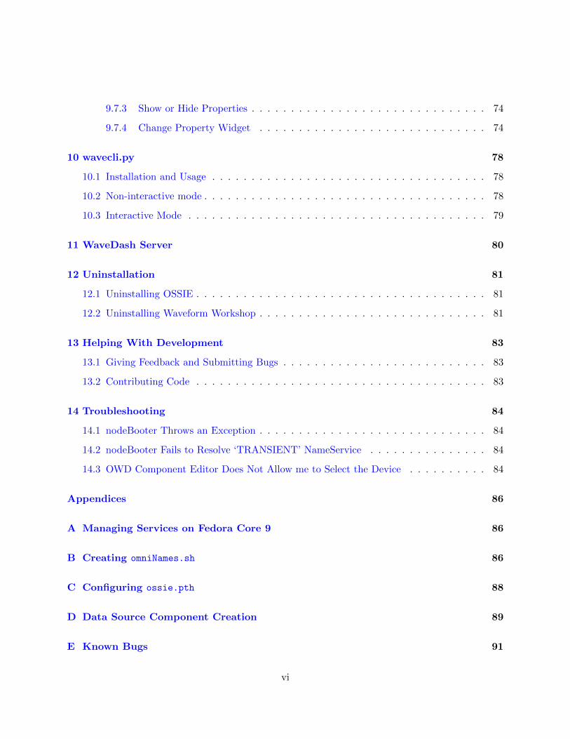
Once the OSSIE VMware image has booted up, open a terminal window by navigating to Appli-cations →System Tools→Terminal. The first thing that needs to be started is the naming service.Type as root:
# omniNames.sh
The terminal should look like figure 1.
The next service that needs to be started is nodeBooter. Open a new tab or a completely newterminal and type the commands in the listing below. You can press tab after the first couple ofletters of a command, directory or filename to have it automatically completed, saving time and
1
Figure 1: omniNames Loaded
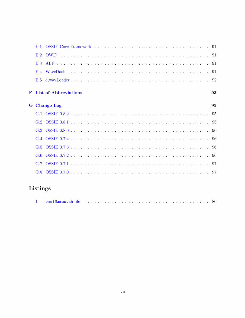
perhaps avoiding typos.
$ cd /sdr/
$ nodeBooter -D -d dev/nodes/default_GPP_node/DeviceManager.dcd.xml
The terminal should look like figure 2.
Figure 2: nodeBooter running
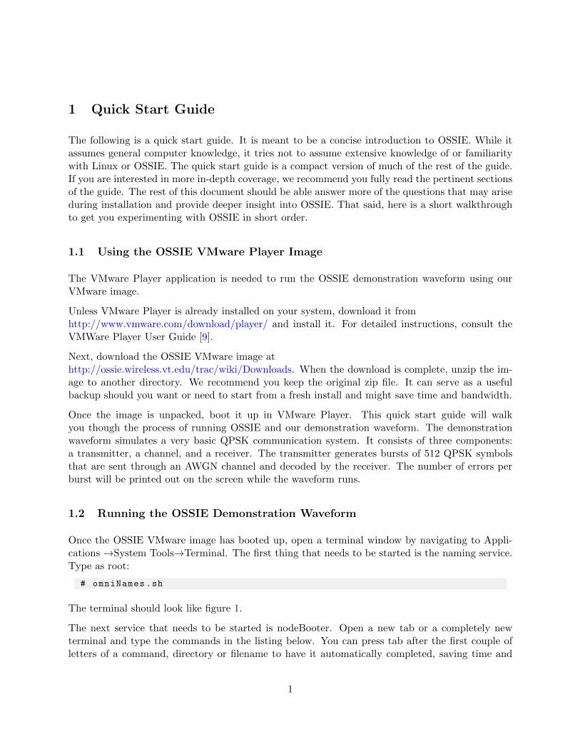
Now load the waveform using wavLoader. In a third tab or terminal, type in:
$ cd /sdr/waveforms/ossie_demo
$ wavLoader.py ossie_demo_DAS.xml
The terminal should look similar to figure 3.
The terminal will list all of the available waveforms to run. Although multiple waveforms may belisted, only the waveform that the wavLoader command was started with will work.
2
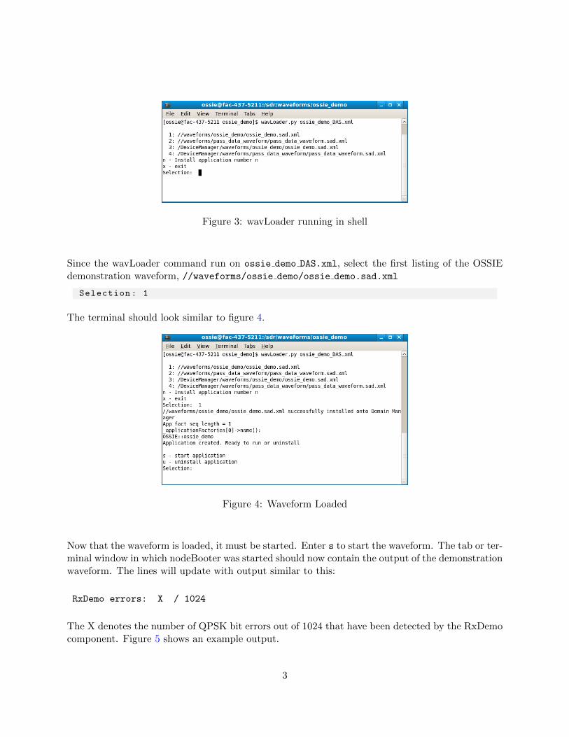
Figure 3: wavLoader running in shell
Since the wavLoader command run on ossie demo DAS.xml, select the first listing of the OSSIEdemonstration waveform, //waveforms/ossie demo/ossie demo.sad.xml
Selection: 1
The terminal should look similar to figure 4.
Figure 4: Waveform Loaded
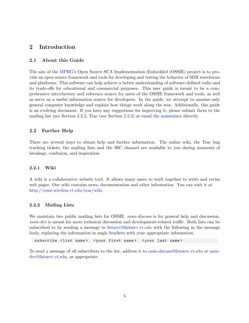
Now that the waveform is loaded, it must be started. Enter s to start the waveform. The tab or ter-minal window in which nodeBooter was started should now contain the output of the demonstrationwaveform. The lines will update with output similar to this:
RxDemo errors: X / 1024
The X denotes the number of QPSK bit errors out of 1024 that have been detected by the RxDemocomponent. Figure 5 shows an example output.
3
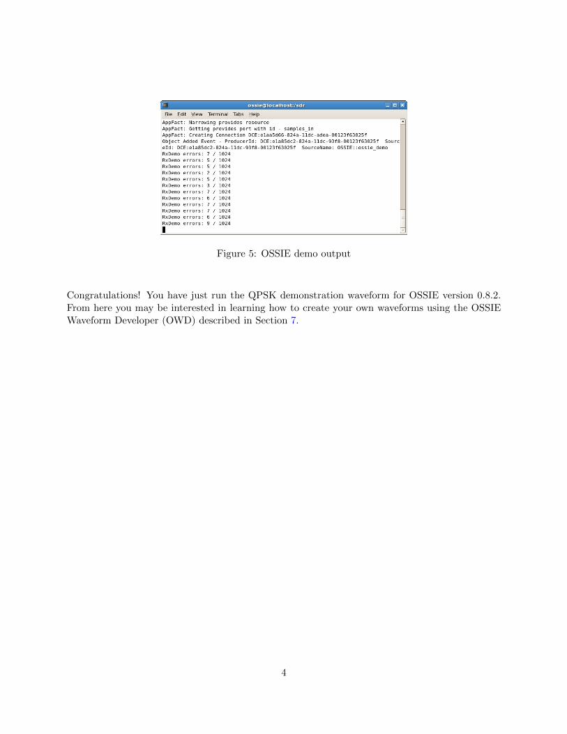
Figure 5: OSSIE demo output
Congratulations! You have just run the QPSK demonstration waveform for OSSIE version 0.8.2.From here you may be interested in learning how to create your own waveforms using the OSSIEWaveform Developer (OWD) described in Section 7.
4
2 Introduction
2.1 About this Guide
The aim of the MPRG’s Open Source SCA Implementation::Embedded (OSSIE) project is to pro-vide an open source framework and tools for developing and testing the behavior of SDR waveformsand platforms. This software can help achieve a better understanding of software-defined radio andits trade-offs for educational and commercial purposes. This user guide is meant to be a com-prehensive introductory and reference source for users of the OSSIE framework and tools, as wellas serve as a useful information source for developers. In the guide, we attempt to assume onlygeneral computer knowledge and explain how things work along the way. Additionally, this guideis an evolving document. If you have any suggestions for improving it, please submit them to themailing list (see Section 2.2.2, Trac (see Section 2.2.3) or email the maintainer directly.
2.2 Further Help
There are several ways to obtain help and further information. The online wiki, the Trac bugtracking tickets, the mailing lists and the IRC channel are available to you during moments ofbreakage, confusion, and inspiration.
2.2.1 Wiki
A wiki is a collaborative website tool. It allows many users to work together to write and reviseweb pages. Our wiki contains news, documentation and other information. You can visit it athttp://ossie.wireless.vt.edu/trac/wiki.
2.2.2 Mailing Lists
We maintain two public mailing lists for OSSIE. ossie-discuss is for general help and discussion.ossie-dev is meant for more technical discussion and development-related traffic. Both lists can besubscribed to by sending a message to [email protected] with the following in the messagebody, replacing the information in angle brackets with your appropriate information.
subscribe <list name > <your first name > <your last name >
To send a message of all subscribers to the list, address it to [email protected] or [email protected], as appropriate.
5
2.2.3 Trac Bug Tracking System
The Trac software provides a web-based interface to our bug tracking database. Reporting pre-viously unreported bugs is extremely helpful to the developers, allowing you to inform them ofproblems not encountered during their testing. Bug trackers are also good places to search forknown problems and work-arounds. You will need to register for an account on the website and login before being allowed to submit new bugs. Visit http://ossie.wireless.vt.edu/trac/newticket toinitiate the bug reporting process. Please be sure to tag the bug with version 0.8.2. We will striveto fix all bugs as soon as possible and incorporate usability and feature improvement suggestionsinto an appropriate future release. If you’re interested in crafting very helpful bug reports, considerreading Simon Tatham’s essay on the topic [13].
2.2.4 The #ossie IRC Channel
There is an OSSIE Internet Relay Chat to aid those interested in real-time communication. Wedo not monitor the channel continuously, but you can email us to set up a time to chat. Ourchannel, #ossie, is on the Freenode network. To visit it, try clicking on the channel name in theprevious sentence or fire up your favorite IRC client, log onto the Freenode servers and join the#ossie channel. If you have never used IRC before, irchelp.org’s IRC Tutorial is a good startingpoint.
6
3 Installation
For users that do not have access to a Linux system, or are unfamiliar with Linux, we recommendthat you use our pre-built VMWare images. These images have OSSIE pre-installed on them, andare ready to use out-of-the-box. Using an OSSIE VMware image is described in Section 3.3.
Although we do not yet provide and support binary installation packages for more Linux distribu-tions, compiling OSSIE from source on them should be possible.
To install OSSIE from source, follow the below instructions to install the OSSIE dependencies, andthen compile and install the source code.
3.1 Installing OSSIE from Source
3.1.1 Notes on OSSIE Installation from Source
This section assumes that the user is familiar with basic Linux commands such as cd and ls.Commands run with root permissions are prefixed with #, while others are prefixed with $.
OSSIE depends on the following software packages:
• Boost - a C++ library of common mechanisms
• omniORB - a CORBA implementation
• omniORBpy - a Python interface for omniORB, necessary for the OSSIE tools and compo-nents
• wxPython - a Python interface for the wxWidgets graphical library, used by the OSSIE tools
• numpy - a Python numerical library used by the OSSIE tools
If you have an older version of OSSIE installed, then you will need to delete the contents of /sdr/.
$ rm -rf /sdr/*
3.1.2 Installing Dependencies on Fedora
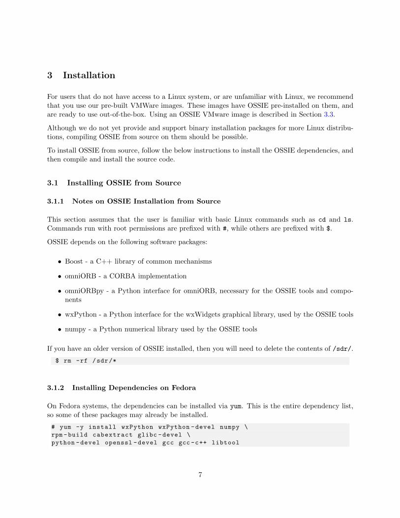
On Fedora systems, the dependencies can be installed via yum. This is the entire dependency list,so some of these packages may already be installed.
# yum -y install wxPython wxPython -devel numpy \
rpm -build cabextract glibc -devel \
python -devel openssl -devel gcc gcc -c++ libtool
7
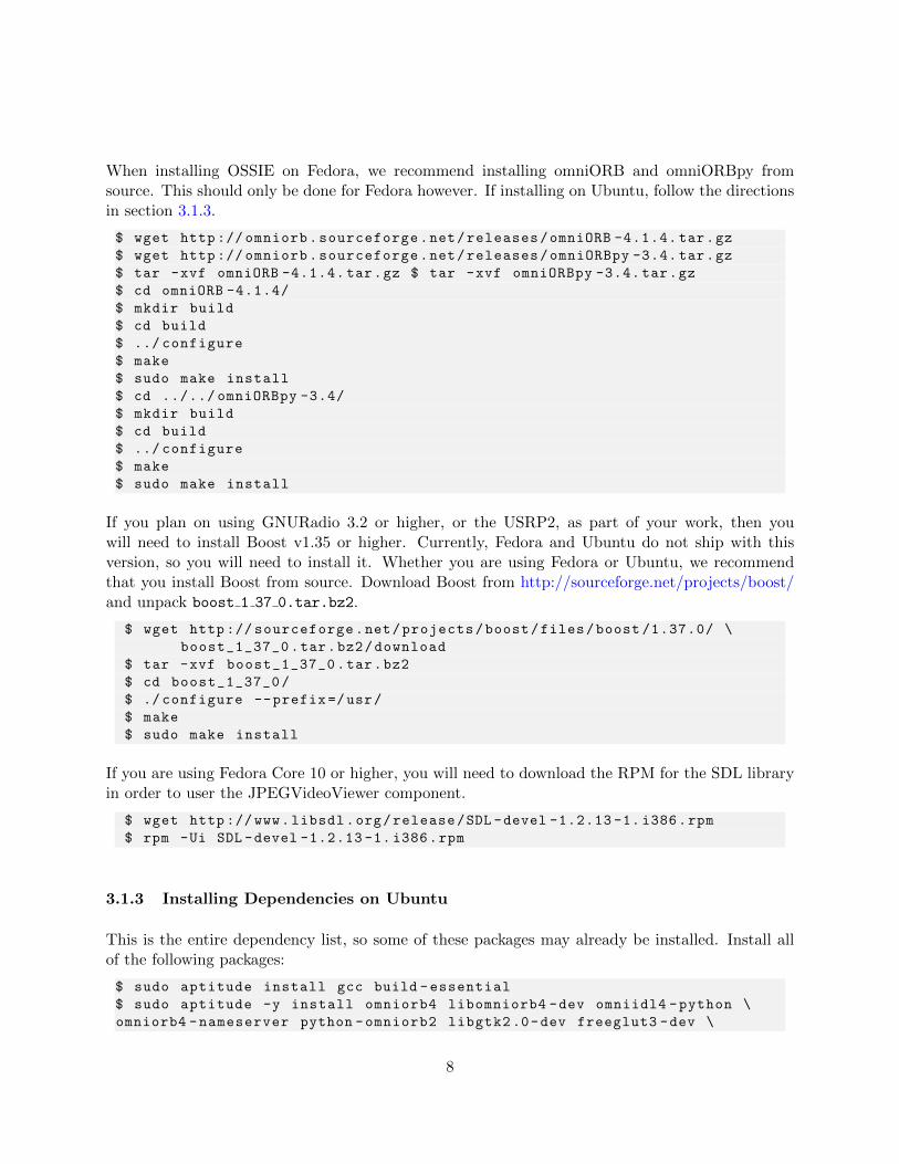
When installing OSSIE on Fedora, we recommend installing omniORB and omniORBpy fromsource. This should only be done for Fedora however. If installing on Ubuntu, follow the directionsin section 3.1.3.
$ wget http :// omniorb.sourceforge.net/releases/omniORB -4.1.4. tar.gz
$ wget http :// omniorb.sourceforge.net/releases/omniORBpy -3.4. tar.gz
$ tar -xvf omniORB -4.1.4. tar.gz $ tar -xvf omniORBpy -3.4. tar.gz
$ cd omniORB -4.1.4/
$ mkdir build
$ cd build
$ ../ configure
$ make
$ sudo make install
$ cd ../../ omniORBpy -3.4/
$ mkdir build
$ cd build
$ ../ configure
$ make
$ sudo make install
If you plan on using GNURadio 3.2 or higher, or the USRP2, as part of your work, then youwill need to install Boost v1.35 or higher. Currently, Fedora and Ubuntu do not ship with thisversion, so you will need to install it. Whether you are using Fedora or Ubuntu, we recommendthat you install Boost from source. Download Boost from http://sourceforge.net/projects/boost/and unpack boost 1 37 0.tar.bz2.
$ wget http :// sourceforge.net/projects/boost/files/boost /1.37.0/ \
boost_1_37_0.tar.bz2/download
$ tar -xvf boost_1_37_0.tar.bz2
$ cd boost_1_37_0/
$ ./ configure --prefix =/usr/
$ make
$ sudo make install
If you are using Fedora Core 10 or higher, you will need to download the RPM for the SDL libraryin order to user the JPEGVideoViewer component.
$ wget http ://www.libsdl.org/release/SDL -devel -1.2.13 -1. i386.rpm
$ rpm -Ui SDL -devel -1.2.13 -1. i386.rpm
3.1.3 Installing Dependencies on Ubuntu
This is the entire dependency list, so some of these packages may already be installed. Install allof the following packages:
$ sudo aptitude install gcc build -essential
$ sudo aptitude -y install omniorb4 libomniorb4 -dev omniidl4 -python \
omniorb4 -nameserver python -omniorb2 libgtk2.0-dev freeglut3 -dev \
8
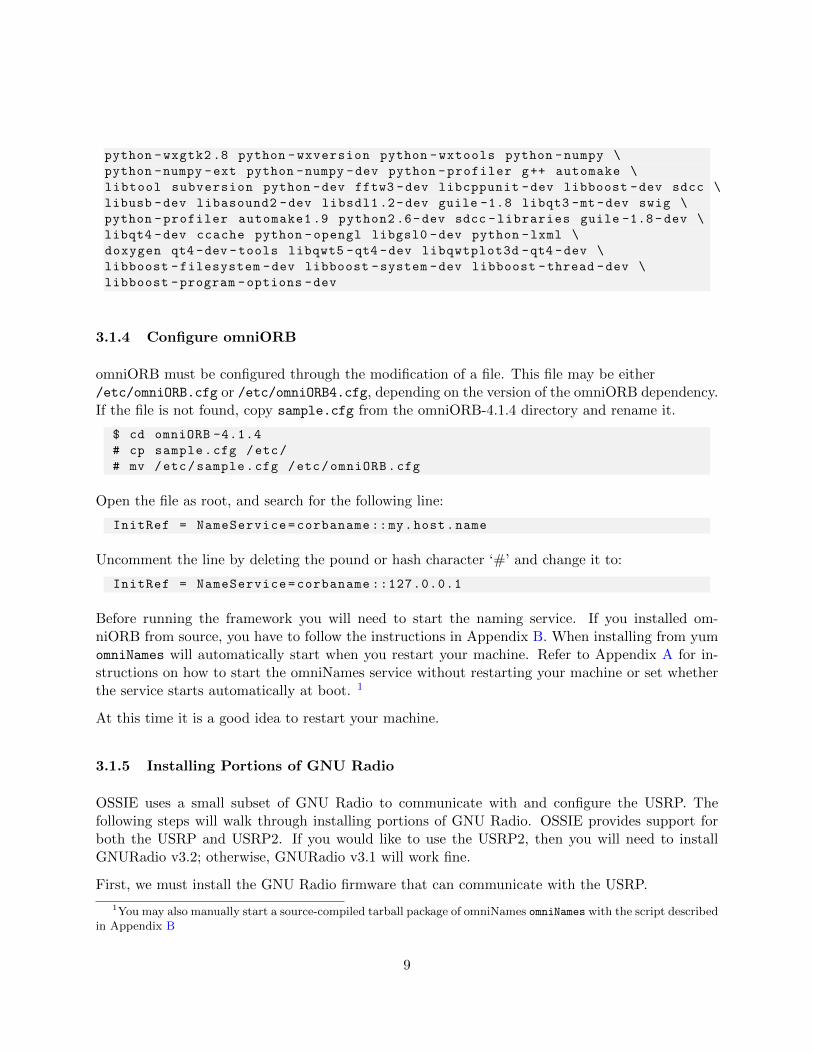
python -wxgtk2 .8 python -wxversion python -wxtools python -numpy \
python -numpy -ext python -numpy -dev python -profiler g++ automake \
libtool subversion python -dev fftw3 -dev libcppunit -dev libboost -dev sdcc \
libusb -dev libasound2 -dev libsdl1.2-dev guile -1.8 libqt3 -mt -dev swig \
python -profiler automake1 .9 python2.6-dev sdcc -libraries guile -1.8-dev \
libqt4 -dev ccache python -opengl libgsl0 -dev python -lxml \
doxygen qt4 -dev -tools libqwt5 -qt4 -dev libqwtplot3d -qt4 -dev \
libboost -filesystem -dev libboost -system -dev libboost -thread -dev \
libboost -program -options -dev
3.1.4 Configure omniORB
omniORB must be configured through the modification of a file. This file may be either/etc/omniORB.cfg or /etc/omniORB4.cfg, depending on the version of the omniORB dependency.If the file is not found, copy sample.cfg from the omniORB-4.1.4 directory and rename it.
$ cd omniORB -4.1.4
# cp sample.cfg /etc/
# mv /etc/sample.cfg /etc/omniORB.cfg
Open the file as root, and search for the following line:
InitRef = NameService=corbaname ::my.host.name
Uncomment the line by deleting the pound or hash character ‘#’ and change it to:
InitRef = NameService=corbaname ::127.0.0.1
Before running the framework you will need to start the naming service. If you installed om-niORB from source, you have to follow the instructions in Appendix B. When installing from yumomniNames will automatically start when you restart your machine. Refer to Appendix A for in-structions on how to start the omniNames service without restarting your machine or set whetherthe service starts automatically at boot. 1
At this time it is a good idea to restart your machine.
3.1.5 Installing Portions of GNU Radio
OSSIE uses a small subset of GNU Radio to communicate with and configure the USRP. Thefollowing steps will walk through installing portions of GNU Radio. OSSIE provides support forboth the USRP and USRP2. If you would like to use the USRP2, then you will need to installGNURadio v3.2; otherwise, GNURadio v3.1 will work fine.
First, we must install the GNU Radio firmware that can communicate with the USRP.
1You may also manually start a source-compiled tarball package of omniNames omniNames with the script describedin Appendix B
9
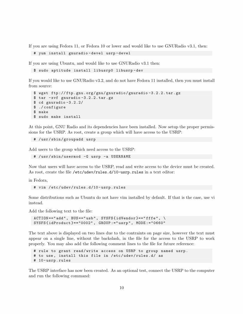
If you are using Fedora 11, or Fedora 10 or lower and would like to use GNURadio v3.1, then:
# yum install gnuradio -devel usrp -devel
If you are using Ubuntu, and would like to use GNURadio v3.1 then:
$ sudo aptitude install libusrp0 libusrp -dev
If you would like to use GNURadio v3.2, and do not have Fedora 11 installed, then you must installfrom source:
$ wget ftp://ftp.gnu.org/gnu/gnuradio/gnuradio -3.2.2. tar.gz
$ tar -xvf gnuradio -3.2.2. tar.gz
$ cd gnuradio -3.2.2/
$ ./ configure
$ make
$ sudo make install
At this point, GNU Radio and its dependencies have been installed. Now setup the proper permis-sions for the USRP. As root, create a group which will have access to the USRP:
# /usr/sbin/groupadd usrp
Add users to the group which need access to the USRP:
# /usr/sbin/usermod -G usrp -a USERNAME
Now that users will have access to the USRP, read and write access to the device must be created.As root, create the file /etc/udev/rules.d/10-usrp.rules in a text editor:
in Fedora,
# vim /etc/udev/rules.d/10-usrp.rules
Some distributions such as Ubuntu do not have vim installed by default. If that is the case, use viinstead.
Add the following text to the file:
ACTION ==" add", BUS ==" usb", SYSFS{idVendor }==" fffe", \
SYSFS{idProduct }=="0002" , GROUP :=" usrp", MODE :="0660"
The text above is displayed on two lines due to the contraints on page size, however the text mustappear on a single line, without the backslash, in the file for the access to the USRP to workproperly. You may also add the following comment lines to the file for future reference:
# rule to grant read/write access on USRP to group named usrp.
# to use , install this file in /etc/udev/rules.d/ as
# 10-usrp.rules
The USRP interface has now been created. As an optional test, connect the USRP to the computerand run the following command:
10
$ ls -lR /dev/bus/usb
The users root and usrp should now be listed under the user groups.
If you are using the USRP2, it is necessary to have a gigabit ethernet interface and intruct thekernel to allow raw socket access to the ethernet port:
# chmod u+s /usr/local/bin/usrp2_socket_opener
This step is necessary every time you reinstall GNU Radio.
3.1.6 Install OSSIE
You are now ready to build and install OSSIE. Note that installing by hand requires some knowledgeof OSSIE, Linux, and software development.
Download the latest tarball from http://ossie.wireless.vt.edu/download/tarballs/0.8.2/and unpack ossie-0.8.2.tar.gz.
$ wget http :// ossie.wireless.vt.edu/download/tarballs /0.8.1/ \
ossie -0.8.1. tar.gz
$ tar -xvf ossie -0.8.1. tar.gz
By default, the installation directory of the OSSIE platform is /sdr. In order to install new sourcecode and binaries into this directory without root permissions, you need to create and change theownership of /sdr.
# sudo mkdir /sdr
# chown -R username.username /sdr
where username is your user name.
3.1.7 Using Autoconf
$ cd ossie -0.8.1
$ ./ configure --prefix =/sdr --libdir =/usr/local/lib/ \
--includedir =/usr/local/include/ --with -boost --with -boost -filesystem
$ make
$ sudo make install
If you prefer, or require, a different root directory, then change the ’–prefix’ flag to your appropriateabsolute path. If you require the OSSIE libraries to be installed to a different location, then changethe ’–libdir’ flag to your appropriate absolute path. For further ’configure’ options, use configure
--help.
11
If configure fails, use aptitude search <dependency name>
3.1.8 Updating System Libraries
Once the OSSIE libraries are installed, they need to be linked. As root edit the file /etc/ld.so.conf,adding the line
/usr/local/lib
Now run:
# /sbin/ldconfig
OSSIE should now be successfully installed on your system. You can skip to Section 4 to learn howto run waveforms.
3.2 Installation of OSSIE Eclipse Feature
Installation of the OSSIE Eclipse Feature (OEF) requires the installation of OSSIE, Java, andEclipse.
3.2.1 Installing Java
Eclipse is written in Java, so you must have it installed to run Eclipse and OEF. We recommendusing Sun’s Java Development Kit. As of this writing, the GNU Compiler for Java (GCJ) will notwork.
Fedora Core 9 comes with the Sun JDK pre-installed but older versions require manual installation.On other distributions it is advisable to use the package manager to manage the installation, ifpossible.
3.2.2 Installing Java on Older Versions of Fedora
Go to http://java.sun.com/javase/downloads/index.jsp and click Download next to JDK 6 Update6. Choose Linux in the platform drop down menu, click the check-box agreeing to the license agree-ment, and click continue. Download the Linux rpm in self extracting file, jdk-6u6-linux-i586-rpm.bin.
Open a terminal and navigate to the file. As root, execute the following command:
# sh jdk -u6-linux -i586 -rpm.bin
Create java.sh in /etc/profile.d/ with the following contents:
export JAVA_HOME ="/ usr/java/latest"
export JAVA_PATH =" $JAVA_HOME"
export PATH=" $PATH:$JAVA_HOME/bin"
12
Log out and back in to allow the changes to update.
3.2.3 Installing Java on Ubuntu
Open /etc/apt/sources.list in an editor and add the following lines to the end of the file:
deb http :// archive.canonical.com/ubuntu lucid partner
deb -src http :// archive.canonical.com/ubuntu lucid partner
In a terminal, enter the following lines:
$ sudo apt -get update
$ sudo apt -get install sun -java6 -jdk
3.2.4 Installing Eclipse
Install the Eclipse IDE for Java Developers. Go to the Eclipse Download Center and download anEclipse distribution for your platform.
Eclipse is distributed as a tarball archive that you can unpack to location of your choice. Picka location that is appropriate for your platform and simply unpack the contents. There is noself-installer, just unpack the distribution. Do not install Eclipse in a directory that has spacesanywhere in its full path name.
3.2.5 Installing OEF
Now that the dependencies have been installed, OEF can be installed.
Move into the unpacked eclipse directory, and start eclipse:
$ cd /path/to/eclipse
$ ./ eclipse
After Eclipse starts, on the toolbar select Help, Install New Software. In the new window,select the “Work with” textbox and enter the URL: http://ossie.wireless.vt.edu/eclipse/and select Add. Give a name, e.g., “OEF”.
The window will then add the URL, OSSIE, OSSIE Waveform Developer Feature to the list ofavailable software. Place a check in the box next to OSSIE Waveform Developer Feature and clickNext. Eclipse will show a window with more details, select Finish to complete the installationprocess.
Allow Eclipse to restart when it prompts to do so. After it restarts, the OSSIE Eclipse Feature willbe installed.
13
Select the OSSIE perspective within Eclipse. On the toolbar, select Window, Open Perspective,Other. In the new window, select OSSIE which will then open the OSSIE perspective. On thetoolbar, select File, New, OSSIE Waveform, or OSSIE Component to start developing.
These same instructions used for installing OEF can be used later to update it to newer versions.
3.3 Using a VMware Image on Any Platform
A VMware image of a complete Fedora Core 9-based Linux system with all necessary dependenciesand a complete install of OSSIE 0.8.2 is available athttp://ossie.wireless.vt.edu/trac/wiki/Downloads. All that is needed to run the virtual image isthe VMWare Player, available for no fee fromhttp://www.vmware.com/download/player/. Versions of the player are available for both Windowsand Linux.
Install VMware Player on your system, unzip the virtual image and open it. For full instructionson installing and using VMware player, please consult the VMWare Player User Guide [9].
It is recommended that you keep a copy of the zipped virtual image so that you do not need todownload the image a second time to start with a fresh copy. Changes that you make from withinthe image will alter it, and in the event of drastic unwanted changes, starting afresh is easy if youhave an extra copy of the image on your hard drive.
14
4 Running Waveforms
4.1 Starting the CORBA Naming Service
If you installed omniORB using rpm or your system package manager and have since restartedyour machine chances are the naming service is running. Refer to Appendix A for how to manageservices under Fedora Core 9. If you chose to install omniNames from source, you will need to runomniNames.sh (see Appendix B).
If using Ubuntu, you can restart omninames using the command
$ sudo service omniorb4 -nameserver restart
4.2 Running nodeBooter
To run nodeBooter, open a terminal and execute the following:
$ cd /sdr
$ nodeBooter -D -d dev/nodes/default_GPP_node/DeviceManager.dcd.xml
It is important that nodeBooter be run from the /sdr directory because nodeBooter uses pathsthat are defined relatively to the directory in which it is run.
4.3 Nodebooter Clean-Up
If a waveform crashes or is uninstalled incorrectly, Nodebooter will not be able to shut down all ofthe processes that it starts. This is currently being addressed by the development team, howeverin the interim the processes must be stopped by hand. To find which processes were not stopped,enter the following command:
$ ps -e
This will list all of the currently running processes. Processes with the names of components ordevices that are in the waveform need to be shutdown. To stop a process, enter the followingcommand:
$ killall USRP GPP <MORE -DEVICES > TxDemo Decimator <MORE -COMPONENTS >
If the USRP node (default GPP USRP sound node) cannot be started, this is typically resolvedby killing the USRP, soundCardPlayback and soundCardCapture devices.
To make this process faster, create a script to kill all of the processes created by a certain waveform.For example, create a text file called killOSSIEprocesses.
$ cd ~
$ vim killOSSIEprocesses
15
or
$ vi killOSSIEprocesses
In this text file, press i to insert text and enter the following on a single line:
killall GPP TxDemo ChannelDemo RxDemo
Press <ESC>, :wq, and then <ENTER> to save the file and exit. Now change the permissions so thescript can be executed.
$ chmod +x killOSSIEprocesses
Now the script has been created and can be run by entering the command:
$ ./ killOSSIEprocesses
If not all processes within the script are running a warning will be printed stating that the processhas not been killed, which is fine.
4.4 Loading a Waveform
The 0.8.2 release supports two options for loading a waveform:
1. The command-line c wavLoader utility discussed below
2. The graphical tool ALF described in Section 8
Directions here are for running the OSSIE demonstration waveform, ossie demo. The demonstra-tion waveform simulates a very basic QPSK communication system. It consists of three components:a transmitter, a channel, and a receiver. The transmitter generates bursts of 512 QPSK symbolsthat are sent through an AWGN channel and decoded by the receiver. The number of errorsper burst will be printed out on the screen while the waveform runs. To run another waveform,substitute ossie demo with the name of your waveform.
Load the waveform using c wavLoader. In a terminal window, execute:
$ c_wavLoader
One or more SAD files (ending in .sad.xml) will be listed. To load the waveform, enter the numberthat corresponds to ossie demo.sad.xml. Finally, enter s to start the waveform.
The terminal window in which nodeBooter was started will now contain the output of the demon-stration waveform. The lines will update with output similar to this:
RxDemo errors: X / 1024
16
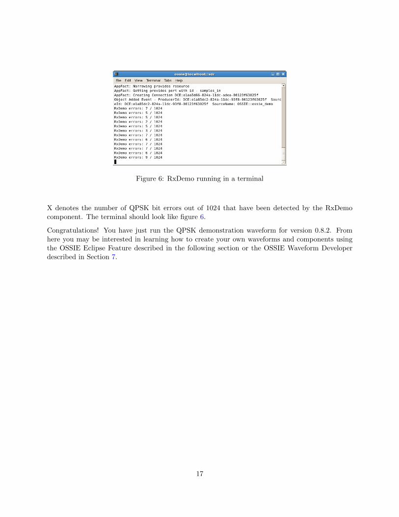
Figure 6: RxDemo running in a terminal
X denotes the number of QPSK bit errors out of 1024 that have been detected by the RxDemocomponent. The terminal should look like figure 6.
Congratulations! You have just run the QPSK demonstration waveform for version 0.8.2. Fromhere you may be interested in learning how to create your own waveforms and components usingthe OSSIE Eclipse Feature described in the following section or the OSSIE Waveform Developerdescribed in Section 7.
17
5 Waveform Workshop
The Waveform Workshop is the collection of development and debugging tools associated with theOSSIE Core Framework. The Waveform Workshop comprises the OSSIE Eclipse Feature (Section6), OSSIE Waveform Developer (Section 7), ALF Graphical Debugging (Section 8), and WaveDash(Section 9).
5.1 OSSIE Eclipse Feature
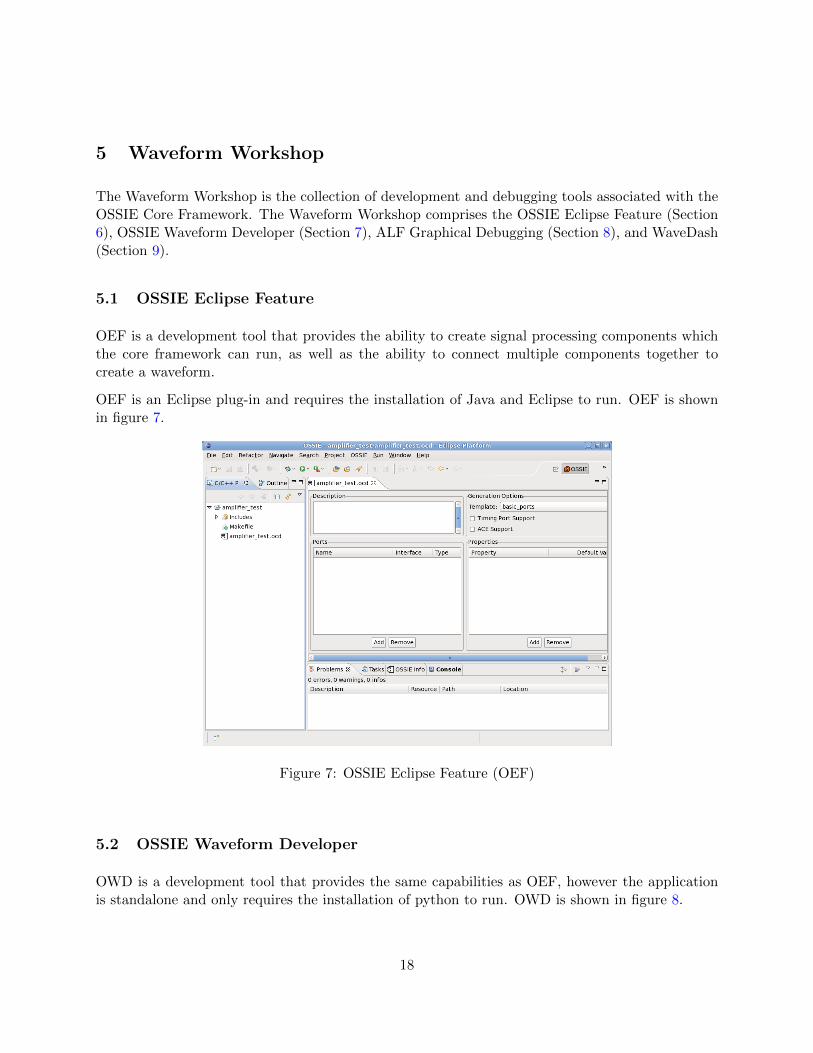
OEF is a development tool that provides the ability to create signal processing components whichthe core framework can run, as well as the ability to connect multiple components together tocreate a waveform.
OEF is an Eclipse plug-in and requires the installation of Java and Eclipse to run. OEF is shownin figure 7.
Figure 7: OSSIE Eclipse Feature (OEF)
5.2 OSSIE Waveform Developer
OWD is a development tool that provides the same capabilities as OEF, however the applicationis standalone and only requires the installation of python to run. OWD is shown in figure 8.
18
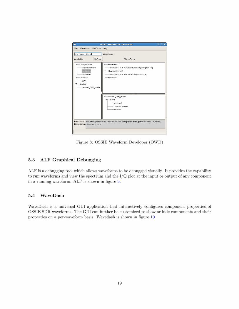
Figure 8: OSSIE Waveform Developer (OWD)
5.3 ALF Graphical Debugging
ALF is a debugging tool which allows waveforms to be debugged visually. It provides the capabilityto run waveforms and view the spectrum and the I/Q plot at the input or output of any componentin a running waveform. ALF is shown in figure 9.
5.4 WaveDash
WaveDash is a universal GUI application that interactively configures component properties ofOSSIE SDR waveforms. The GUI can further be customized to show or hide components and theirproperties on a per-waveform basis. Wavedash is shown in figure 10.
19
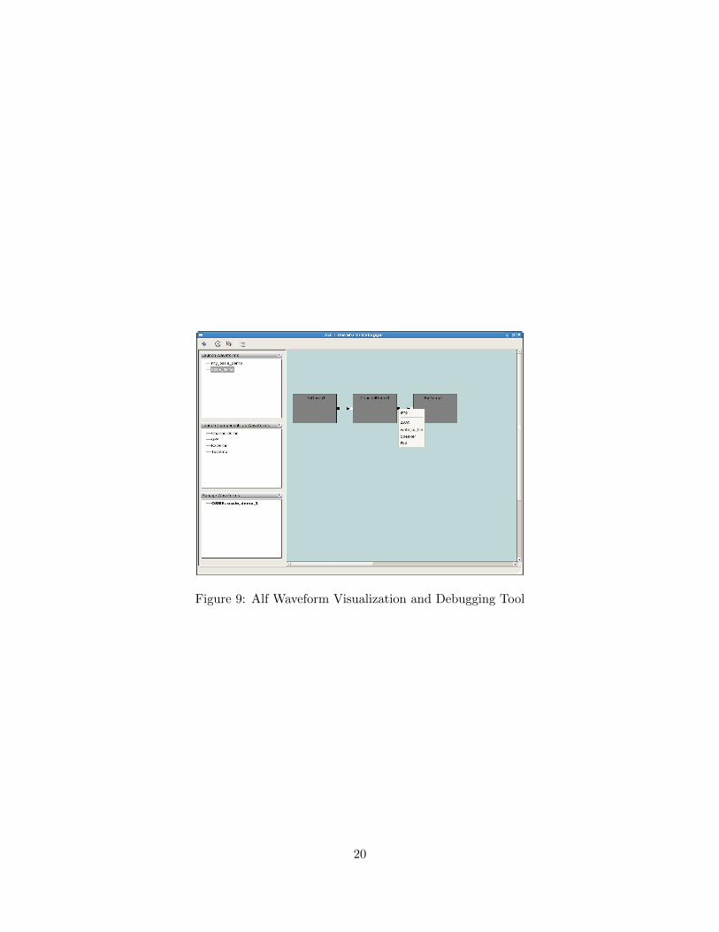
Figure 9: Alf Waveform Visualization and Debugging Tool
20
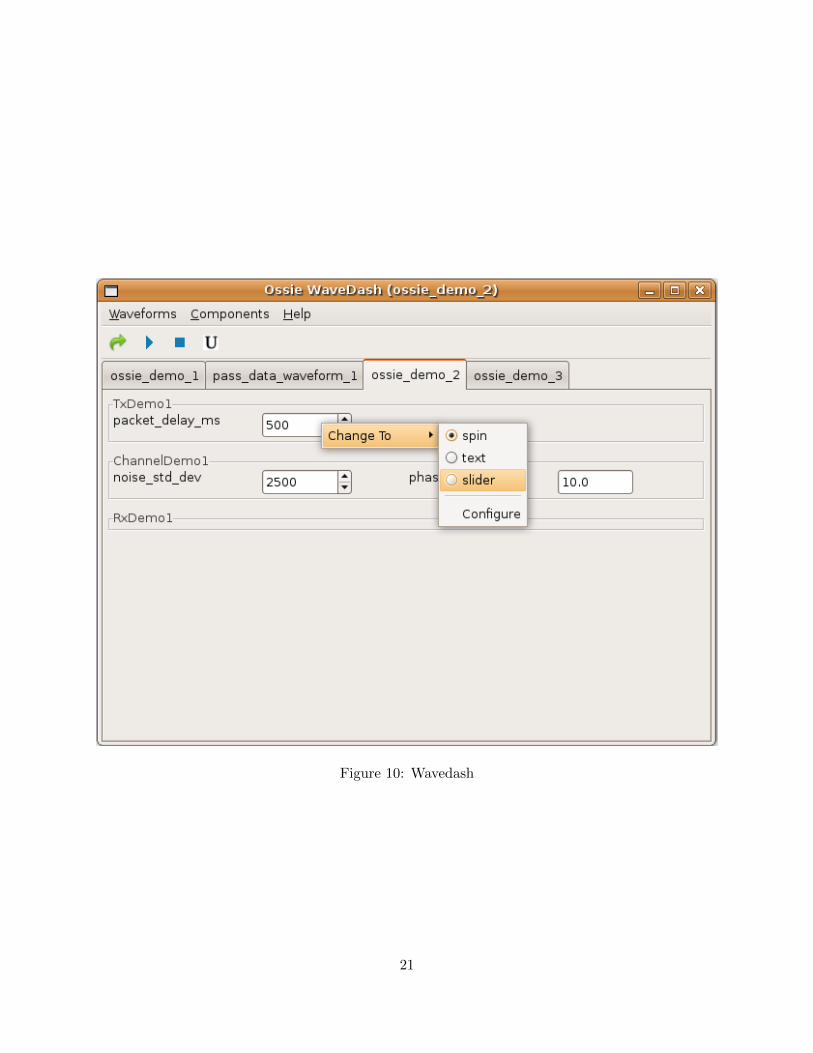
Figure 10: Wavedash
21
6 OSSIE Eclipse Feature
The OSSIE Eclipse Feature (OEF) is an interface for working with OSSIE tools and the coreframework. OEF provides a drag and drop interface for creating waveforms, as well as creatingcomponents and interfacing with the OSSIE core framework.
6.1 Creating a New Waveform from Existing Components
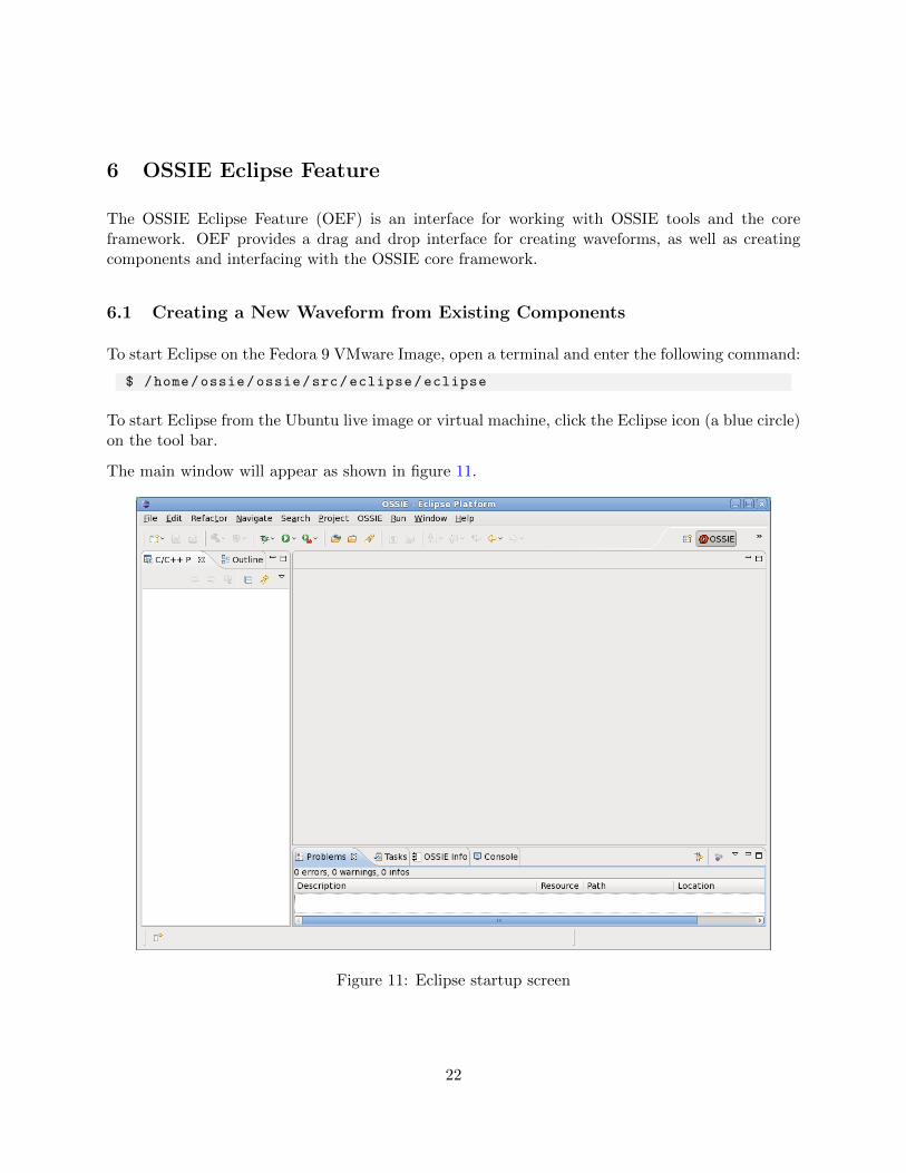
To start Eclipse on the Fedora 9 VMware Image, open a terminal and enter the following command:
$ /home/ossie/ossie/src/eclipse/eclipse
To start Eclipse from the Ubuntu live image or virtual machine, click the Eclipse icon (a blue circle)on the tool bar.
The main window will appear as shown in figure 11.
Figure 11: Eclipse startup screen
22
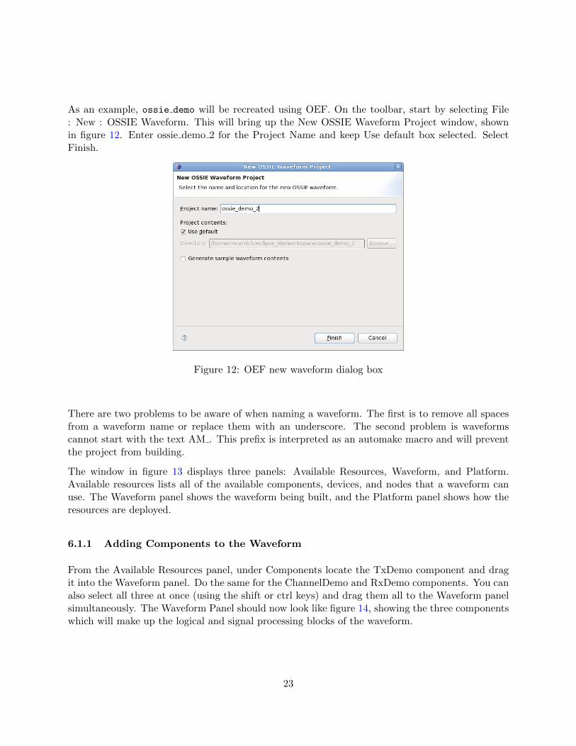
As an example, ossie demo will be recreated using OEF. On the toolbar, start by selecting File: New : OSSIE Waveform. This will bring up the New OSSIE Waveform Project window, shownin figure 12. Enter ossie demo 2 for the Project Name and keep Use default box selected. SelectFinish.
Figure 12: OEF new waveform dialog box
There are two problems to be aware of when naming a waveform. The first is to remove all spacesfrom a waveform name or replace them with an underscore. The second problem is waveformscannot start with the text AM . This prefix is interpreted as an automake macro and will preventthe project from building.
The window in figure 13 displays three panels: Available Resources, Waveform, and Platform.Available resources lists all of the available components, devices, and nodes that a waveform canuse. The Waveform panel shows the waveform being built, and the Platform panel shows how theresources are deployed.
6.1.1 Adding Components to the Waveform
From the Available Resources panel, under Components locate the TxDemo component and dragit into the Waveform panel. Do the same for the ChannelDemo and RxDemo components. You canalso select all three at once (using the shift or ctrl keys) and drag them all to the Waveform panelsimultaneously. The Waveform Panel should now look like figure 14, showing the three componentswhich will make up the logical and signal processing blocks of the waveform.
23
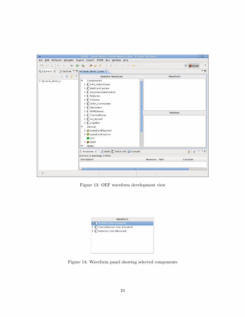
Figure 13: OEF waveform development view
Figure 14: Waveform panel showing selected components
24
6.1.2 Connecting Components
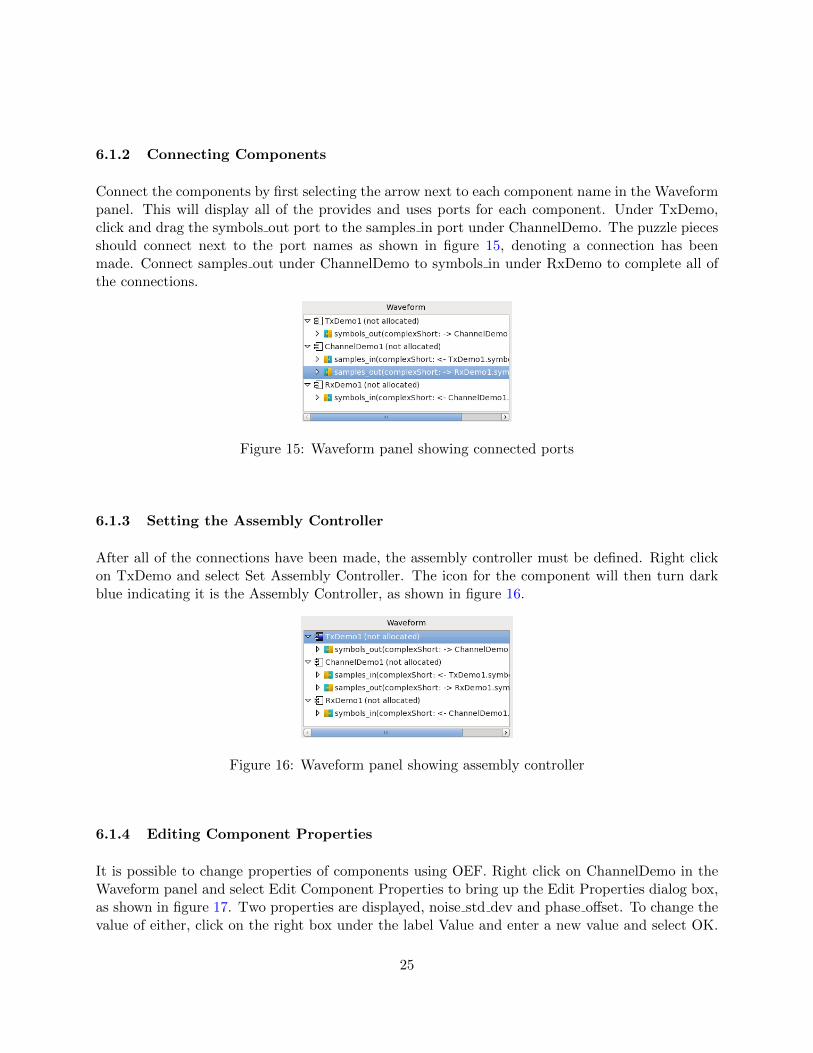
Connect the components by first selecting the arrow next to each component name in the Waveformpanel. This will display all of the provides and uses ports for each component. Under TxDemo,click and drag the symbols out port to the samples in port under ChannelDemo. The puzzle piecesshould connect next to the port names as shown in figure 15, denoting a connection has beenmade. Connect samples out under ChannelDemo to symbols in under RxDemo to complete all ofthe connections.
Figure 15: Waveform panel showing connected ports
6.1.3 Setting the Assembly Controller
After all of the connections have been made, the assembly controller must be defined. Right clickon TxDemo and select Set Assembly Controller. The icon for the component will then turn darkblue indicating it is the Assembly Controller, as shown in figure 16.
Figure 16: Waveform panel showing assembly controller
6.1.4 Editing Component Properties
It is possible to change properties of components using OEF. Right click on ChannelDemo in theWaveform panel and select Edit Component Properties to bring up the Edit Properties dialog box,as shown in figure 17. Two properties are displayed, noise std dev and phase offset. To change thevalue of either, click on the right box under the label Value and enter a new value and select OK.
25
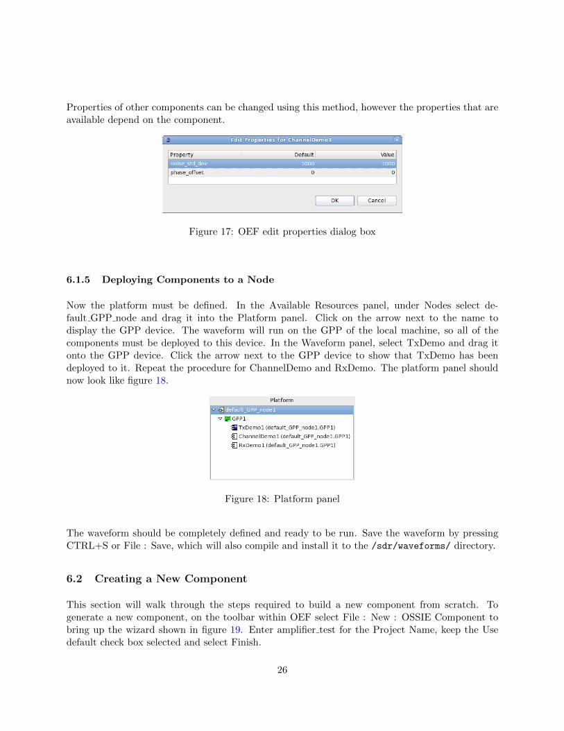
Properties of other components can be changed using this method, however the properties that areavailable depend on the component.
Figure 17: OEF edit properties dialog box
6.1.5 Deploying Components to a Node
Now the platform must be defined. In the Available Resources panel, under Nodes select de-fault GPP node and drag it into the Platform panel. Click on the arrow next to the name todisplay the GPP device. The waveform will run on the GPP of the local machine, so all of thecomponents must be deployed to this device. In the Waveform panel, select TxDemo and drag itonto the GPP device. Click the arrow next to the GPP device to show that TxDemo has beendeployed to it. Repeat the procedure for ChannelDemo and RxDemo. The platform panel shouldnow look like figure 18.
Figure 18: Platform panel
The waveform should be completely defined and ready to be run. Save the waveform by pressingCTRL+S or File : Save, which will also compile and install it to the /sdr/waveforms/ directory.
6.2 Creating a New Component
This section will walk through the steps required to build a new component from scratch. Togenerate a new component, on the toolbar within OEF select File : New : OSSIE Component tobring up the wizard shown in figure 19. Enter amplifier test for the Project Name, keep the Usedefault check box selected and select Finish.
26
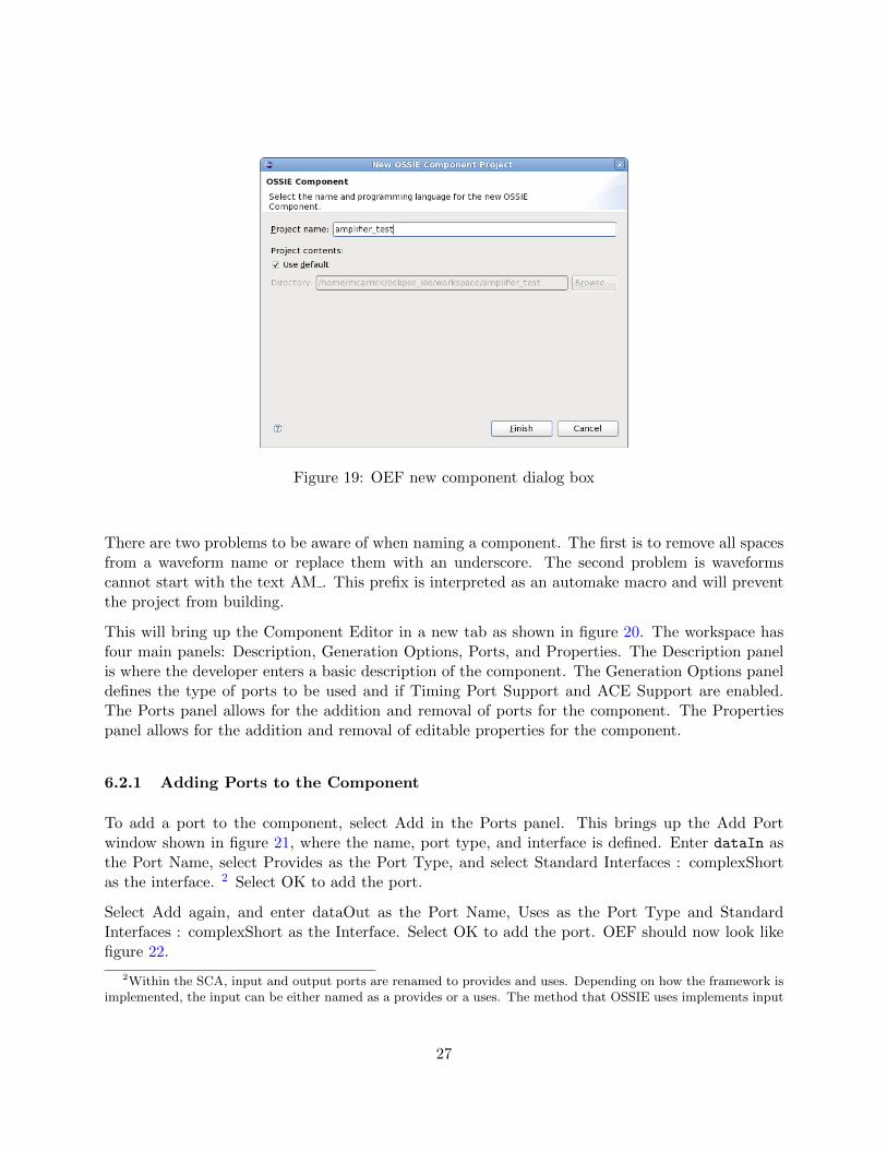
Figure 19: OEF new component dialog box
There are two problems to be aware of when naming a component. The first is to remove all spacesfrom a waveform name or replace them with an underscore. The second problem is waveformscannot start with the text AM . This prefix is interpreted as an automake macro and will preventthe project from building.
This will bring up the Component Editor in a new tab as shown in figure 20. The workspace hasfour main panels: Description, Generation Options, Ports, and Properties. The Description panelis where the developer enters a basic description of the component. The Generation Options paneldefines the type of ports to be used and if Timing Port Support and ACE Support are enabled.The Ports panel allows for the addition and removal of ports for the component. The Propertiespanel allows for the addition and removal of editable properties for the component.
6.2.1 Adding Ports to the Component
To add a port to the component, select Add in the Ports panel. This brings up the Add Portwindow shown in figure 21, where the name, port type, and interface is defined. Enter dataIn asthe Port Name, select Provides as the Port Type, and select Standard Interfaces : complexShortas the interface. 2 Select OK to add the port.
Select Add again, and enter dataOut as the Port Name, Uses as the Port Type and StandardInterfaces : complexShort as the Interface. Select OK to add the port. OEF should now look likefigure 22.
2Within the SCA, input and output ports are renamed to provides and uses. Depending on how the framework isimplemented, the input can be either named as a provides or a uses. The method that OSSIE uses implements input
27
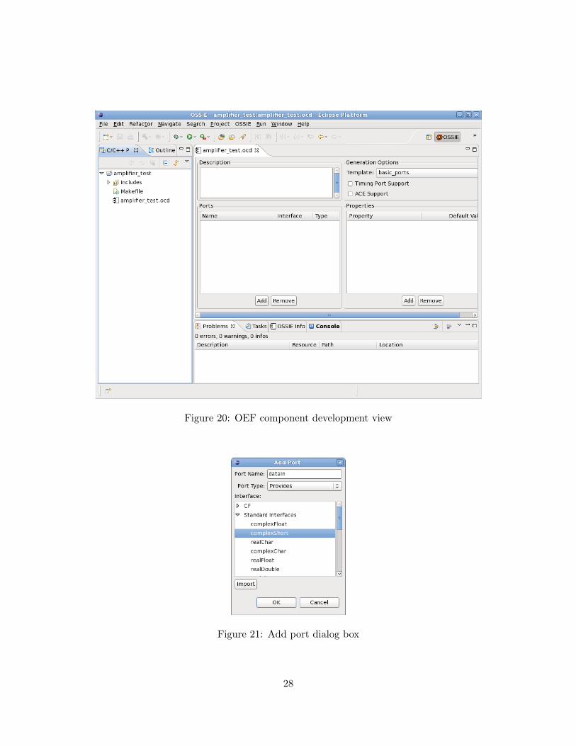
Figure 20: OEF component development view
Figure 21: Add port dialog box
28
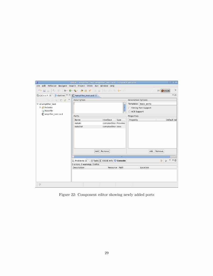
Figure 22: Component editor showing newly added ports
29
6.2.2 Adding Properties to the Component
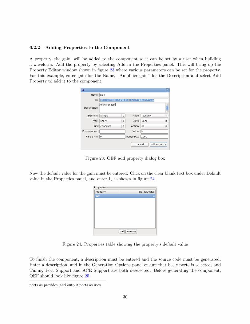
A property, the gain, will be added to the component so it can be set by a user when buildinga waveform. Add the property by selecting Add in the Properties panel. This will bring up theProperty Editor window shown in figure 23 where various parameters can be set for the property.For this example, enter gain for the Name, “Amplifier gain” for the Description and select AddProperty to add it to the component.
Figure 23: OEF add property dialog box
Now the default value for the gain must be entered. Click on the clear blank text box under Defaultvalue in the Properties panel, and enter 1, as shown in figure 24.
Figure 24: Properties table showing the property’s default value
To finish the component, a description must be entered and the source code must be generated.Enter a description, and in the Generation Options panel ensure that basic ports is selected, andTiming Port Support and ACE Support are both deselected. Before generating the component,OEF should look like figure 25.
ports as provides, and output ports as uses.
30
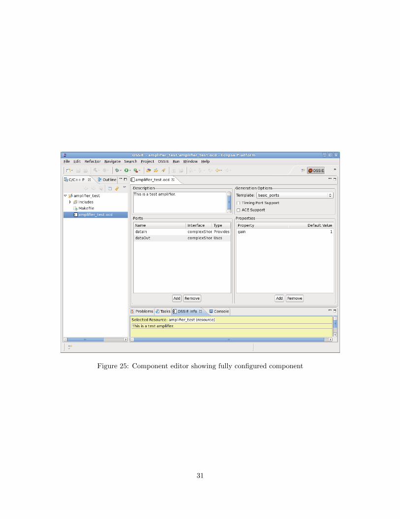
Figure 25: Component editor showing fully configured component
31
6.2.3 Generating the Source Code
On the OEF toolbar, select OSSIE : Generate Component. This generates all of the files for thecomponent in the local eclipse workspace directory.
Generating the component will produce multiple files along with the source code.
1. configure.ac: This is the script that autoconf uses to generate the configure file. It checksfor dependencies such as which compiler to use, as well as the presence of OSSIE libraries.
2. Makefile.am: This is the script that automake uses to generate the Makefile. It includes allthe source files for the component.
3. reconf: This is a script to run the automake tools.
4. component name.h: Component class header file.
5. component name.cpp: Component class implementation definition.
6. main.cpp: Contains the mandatory int main() definition.
7. component name.prf.xml: Component property file.
8. component name.scd.xml: Software component descriptor.
9. component name.spd.xml: Software package descriptor.
10. documentation.txt: File for documenting your component.
11. Doxyfile: Doxygen file for generating documentation.
Additional files are generated when using the py comp option:
1. component name.py: Python file with port implementations.
2. WorkModule.py: Python file where processing is done.
3. setup.py: Install script used to copy Python and XML files into the appropriate subdirec-tories under /sdr once the component is edited to provide functionality. This is executed bytyping python setup.py install.
At this point the signal processing or logical function of the component must be defined. Theprocess for doing so is different depending on whether the component is written in C++ or python.
32
6.2.4 Editing C++ Components
In this example, by selecting basic ports the component was generated as a C++ component. Toedit the component, open component name.cpp by double-clicking on it in the Project Explorerand find the ProcessData function.
Within the function, there will be a while loop and inside of it will be a line:
/* insert code here to do work*/
This is where the signal processing function should be implemented. The property that was gen-erated, gain will be available in the source code initially as simplei 0 value. Reassign this to anew variable named gain in the configure function in the same file.
6.2.5 Editing Python Components
Generated component template code must be modified to process data. The instructions here applyto a very basic Python component with one uses and one provides port and no properties. Propertyvalues can be used in the processing operations, but this will be the subject of a future exercise.
All data coming into a provides port will be loaded into the WorkModule buffer. The data goinginto this buffer will be loaded into variables called I and Q. See the generated WorkModule.py andlook for:
I = new_data [0]
Q = new_data [1]
This implies that if you try to run a component that is getting real data only, Q should be empty,and this may even cause an error. There are comments in various parts of the python files describinghow to adjust your code appropriately.
The next two lines initialize two arrays to store your new data:
newI = [0 for x in range(len(I)))]
newQ = [0 for x in range(len(Q)))]
Following these lines are comments with an example of how to process data. If you uncommentthe 3-line example, your component will pass the data received by the provides (input) port to theuses (output) port, assuming you have one uses port of type complexShort and one provides port,also of type complexShort. Code can be added to process the data.
The next set of lines following the comment “# Output the new data,” will send the newI andnewQ vectors to all of your output ports.
33
6.2.6 Installing a Component
After generating the component files, OEF automatically installs the component to /sdr for you.Every time the project is saved from then on, the component is reinstalled. Note however thatmaking any changes to the ports or properties of the component will require re-generating thecomponent from the OSSIE menu, which will overwrite the component source files. If you makechanges to the source files and later need to re-generate the component, be sure to make temporarycopies of your work so it is not lost.
6.3 Creating a New Node
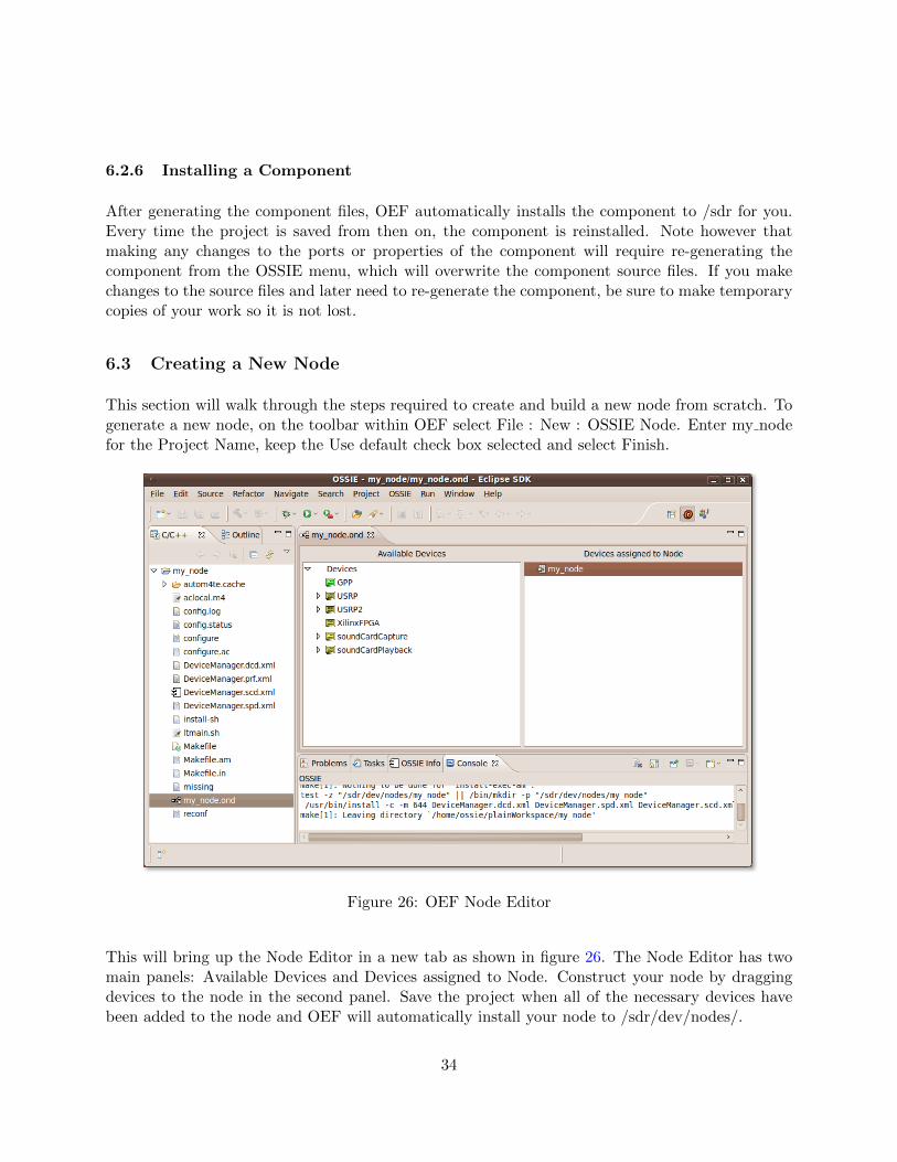
This section will walk through the steps required to create and build a new node from scratch. Togenerate a new node, on the toolbar within OEF select File : New : OSSIE Node. Enter my nodefor the Project Name, keep the Use default check box selected and select Finish.
Figure 26: OEF Node Editor
This will bring up the Node Editor in a new tab as shown in figure 26. The Node Editor has twomain panels: Available Devices and Devices assigned to Node. Construct your node by draggingdevices to the node in the second panel. Save the project when all of the necessary devices havebeen added to the node and OEF will automatically install your node to /sdr/dev/nodes/.
34
6.4 Importing and Exporting Eclipse Projects
Projects developed within Eclipse can be saved to be used as a backup, or to transport to anotherdevelopment platform. This is done by exporting and importing projects.
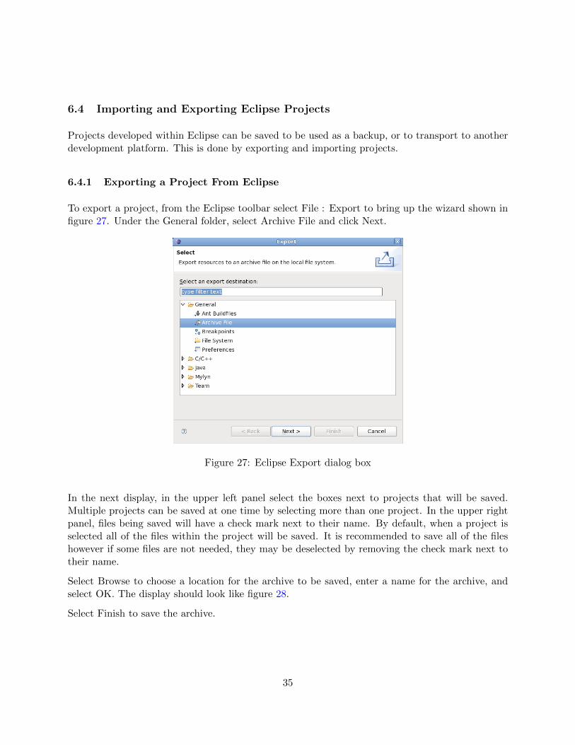
6.4.1 Exporting a Project From Eclipse
To export a project, from the Eclipse toolbar select File : Export to bring up the wizard shown infigure 27. Under the General folder, select Archive File and click Next.
Figure 27: Eclipse Export dialog box
In the next display, in the upper left panel select the boxes next to projects that will be saved.Multiple projects can be saved at one time by selecting more than one project. In the upper rightpanel, files being saved will have a check mark next to their name. By default, when a project isselected all of the files within the project will be saved. It is recommended to save all of the fileshowever if some files are not needed, they may be deselected by removing the check mark next totheir name.
Select Browse to choose a location for the archive to be saved, enter a name for the archive, andselect OK. The display should look like figure 28.
Select Finish to save the archive.
35
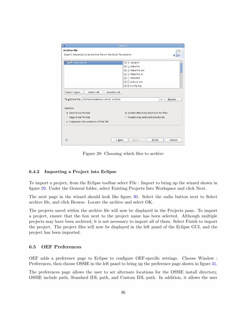
Figure 28: Choosing which files to archive
6.4.2 Importing a Project into Eclipse
To import a project, from the Eclipse toolbar select File : Import to bring up the wizard shown infigure 29. Under the General folder, select Existing Projects Into Workspace and click Next.
The next page in the wizard should look like figure 30. Select the radio button next to Selectarchive file, and click Browse. Locate the archive and select OK.
The projects saved within the archive file will now be displayed in the Projects pane. To importa project, ensure that the box next to the project name has been selected. Although multipleprojects may have been archived, it is not necessary to import all of them. Select Finish to importthe project. The project files will now be displayed in the left panel of the Eclipse GUI, and theproject has been imported.
6.5 OEF Preferences
OEF adds a preference page to Eclipse to configure OEF-specific settings. Choose Window :Preferences, then choose OSSIE in the left panel to bring up the preference page shown in figure 31.
The preferences page allows the user to set alternate locations for the OSSIE install directory,OSSIE include path, Standard IDL path, and Custom IDL path. In addition, it allows the user
36
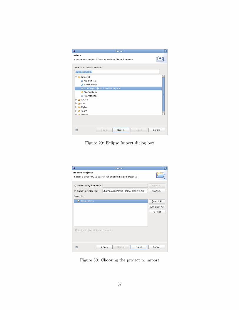
Figure 29: Eclipse Import dialog box
Figure 30: Choosing the project to import
37
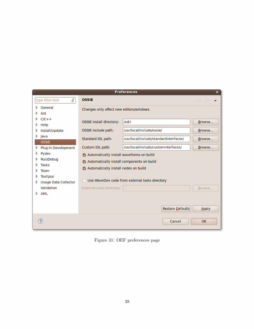
Figure 31: OEF preferences page
38
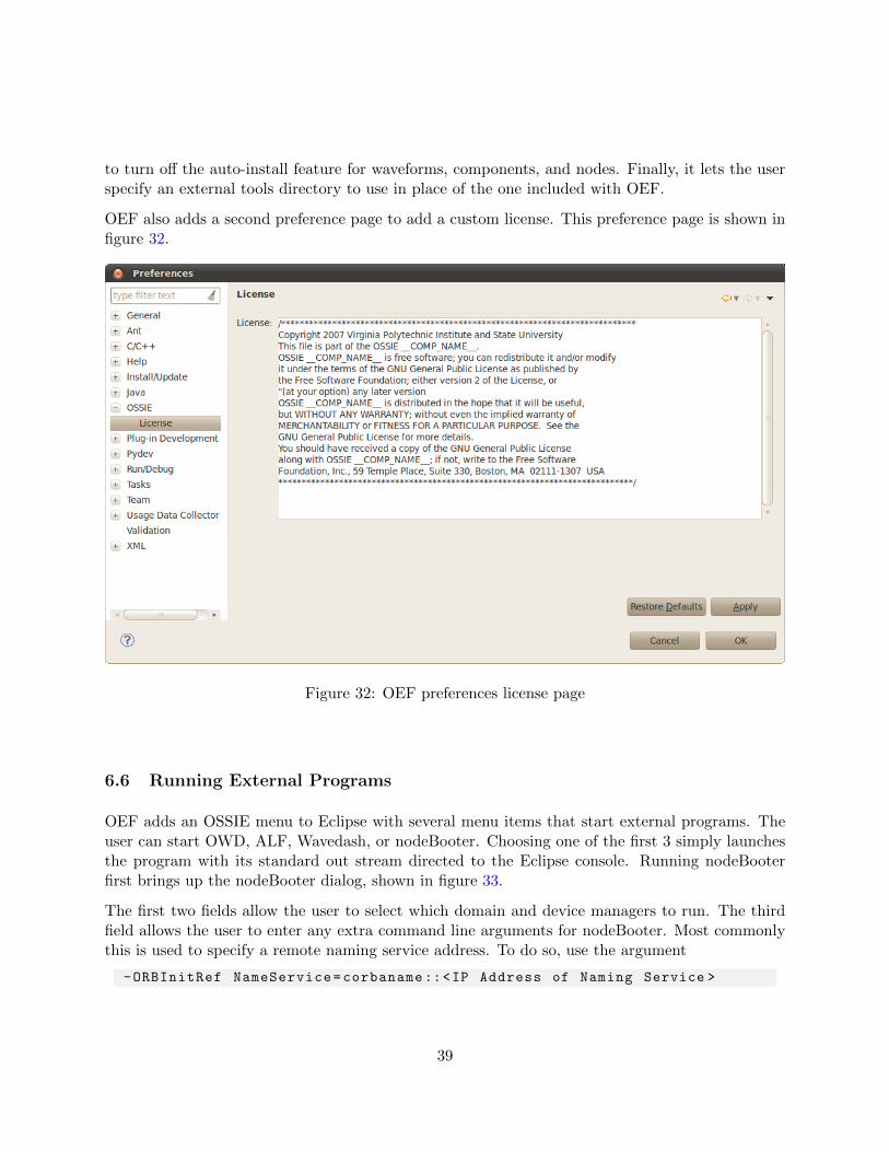
to turn off the auto-install feature for waveforms, components, and nodes. Finally, it lets the userspecify an external tools directory to use in place of the one included with OEF.
OEF also adds a second preference page to add a custom license. This preference page is shown infigure 32.
Figure 32: OEF preferences license page
6.6 Running External Programs
OEF adds an OSSIE menu to Eclipse with several menu items that start external programs. Theuser can start OWD, ALF, Wavedash, or nodeBooter. Choosing one of the first 3 simply launchesthe program with its standard out stream directed to the Eclipse console. Running nodeBooterfirst brings up the nodeBooter dialog, shown in figure 33.
The first two fields allow the user to select which domain and device managers to run. The thirdfield allows the user to enter any extra command line arguments for nodeBooter. Most commonlythis is used to specify a remote naming service address. To do so, use the argument
-ORBInitRef NameService=corbaname::<IP Address of Naming Service >
39
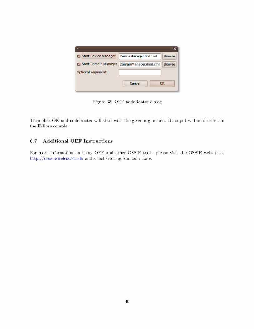
Figure 33: OEF nodeBooter dialog
Then click OK and nodeBooter will start with the given arguments. Its ouput will be directed tothe Eclipse console.
6.7 Additional OEF Instructions
For more information on using OEF and other OSSIE tools, please visit the OSSIE website athttp://ossie.wireless.vt.edu and select Getting Started : Labs.
40
7 OSSIE Waveform Developer
The OSSIE Waveform Developer (OWD) is available for constructing code for waveforms andcomponents based on JTRS’s Software Communications Architecture. A user does not need tohave detailed knowledge of the SCA or CORBA to use the tool. OWD allows you to draw from alibrary of available components to construct an SCA-based waveform or create the skeleton codefor custom-made C++ or Python components.
7.1 Creating a New Waveform from Existing Components
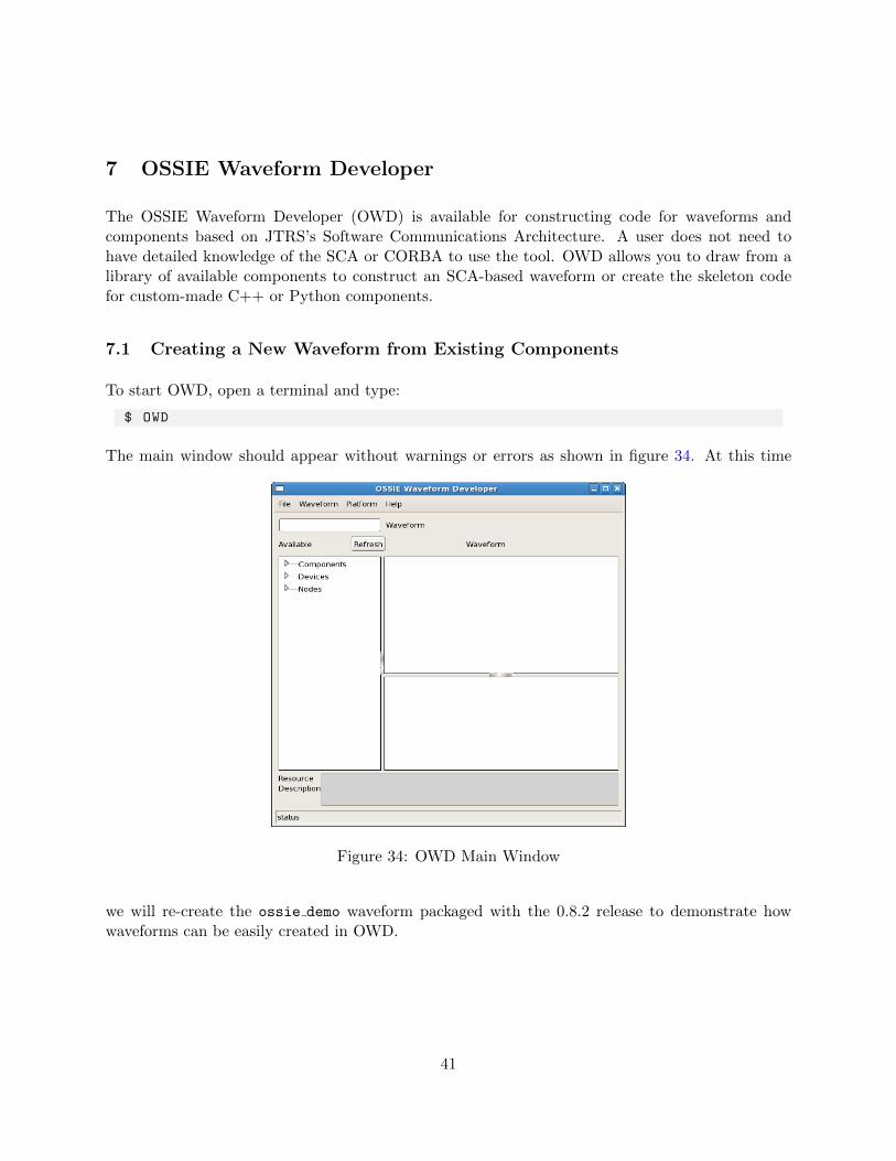
To start OWD, open a terminal and type:
$ OWD
The main window should appear without warnings or errors as shown in figure 34. At this time
Figure 34: OWD Main Window
we will re-create the ossie demo waveform packaged with the 0.8.2 release to demonstrate howwaveforms can be easily created in OWD.
41
7.1.1 Adding an Existing Node to a Waveform
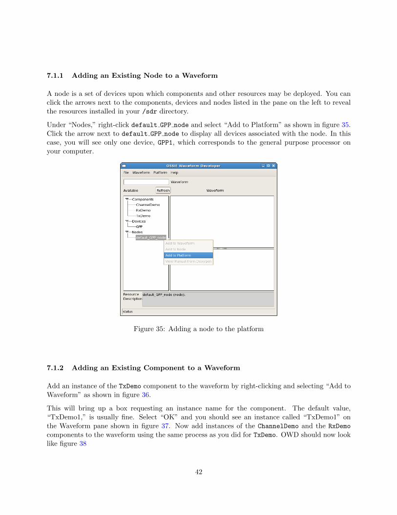
A node is a set of devices upon which components and other resources may be deployed. You canclick the arrows next to the components, devices and nodes listed in the pane on the left to revealthe resources installed in your /sdr directory.
Under “Nodes,” right-click default GPP node and select “Add to Platform” as shown in figure 35.Click the arrow next to default GPP node to display all devices associated with the node. In thiscase, you will see only one device, GPP1, which corresponds to the general purpose processor onyour computer.
Figure 35: Adding a node to the platform
7.1.2 Adding an Existing Component to a Waveform
Add an instance of the TxDemo component to the waveform by right-clicking and selecting “Add toWaveform” as shown in figure 36.
This will bring up a box requesting an instance name for the component. The default value,“TxDemo1,” is usually fine. Select “OK” and you should see an instance called “TxDemo1” onthe Waveform pane shown in figure 37. Now add instances of the ChannelDemo and the RxDemo
components to the waveform using the same process as you did for TxDemo. OWD should now looklike figure 38
42
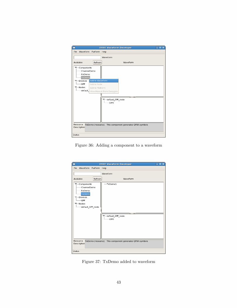
Figure 36: Adding a component to a waveform
Figure 37: TxDemo added to waveform
43
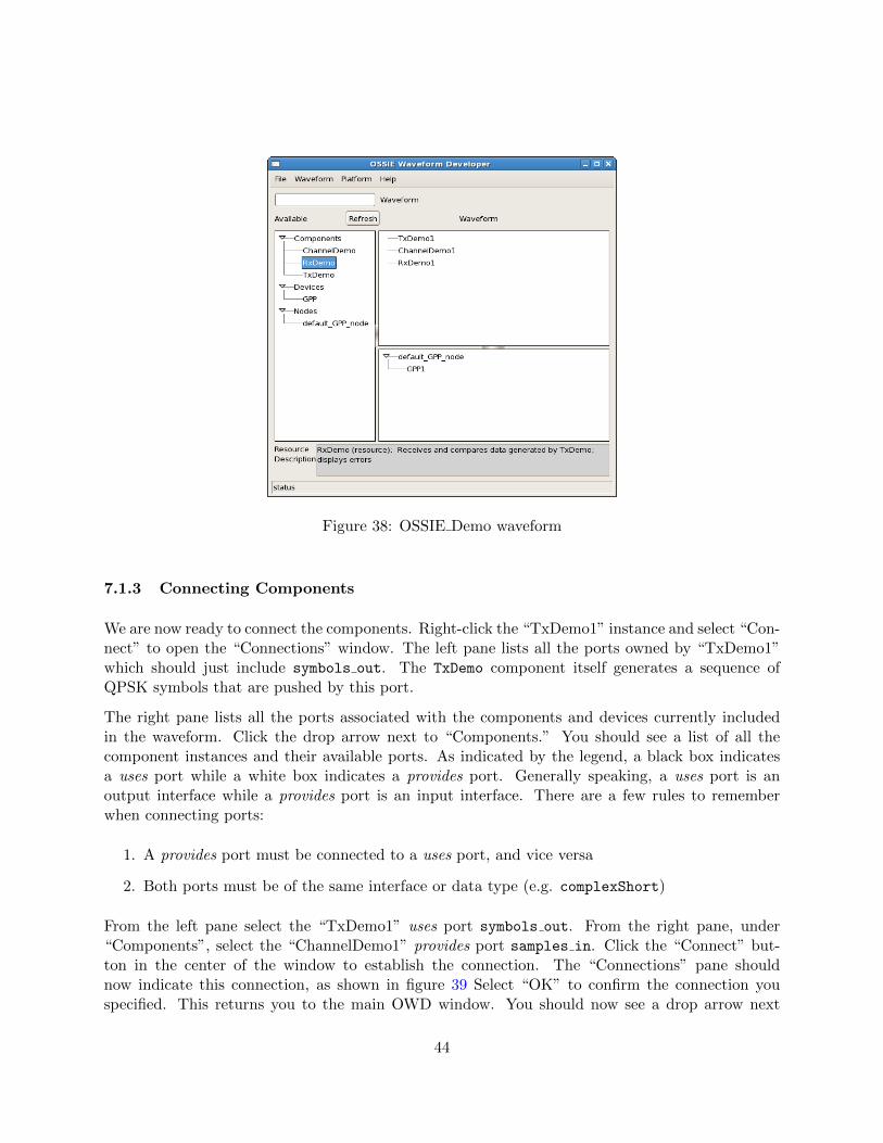
Figure 38: OSSIE Demo waveform
7.1.3 Connecting Components
We are now ready to connect the components. Right-click the “TxDemo1” instance and select “Con-nect” to open the “Connections” window. The left pane lists all the ports owned by “TxDemo1”which should just include symbols out. The TxDemo component itself generates a sequence ofQPSK symbols that are pushed by this port.
The right pane lists all the ports associated with the components and devices currently includedin the waveform. Click the drop arrow next to “Components.” You should see a list of all thecomponent instances and their available ports. As indicated by the legend, a black box indicatesa uses port while a white box indicates a provides port. Generally speaking, a uses port is anoutput interface while a provides port is an input interface. There are a few rules to rememberwhen connecting ports:
1. A provides port must be connected to a uses port, and vice versa
2. Both ports must be of the same interface or data type (e.g. complexShort)
From the left pane select the “TxDemo1” uses port symbols out. From the right pane, under“Components”, select the “ChannelDemo1” provides port samples in. Click the “Connect” but-ton in the center of the window to establish the connection. The “Connections” pane shouldnow indicate this connection, as shown in figure 39 Select “OK” to confirm the connection youspecified. This returns you to the main OWD window. You should now see a drop arrow next
44
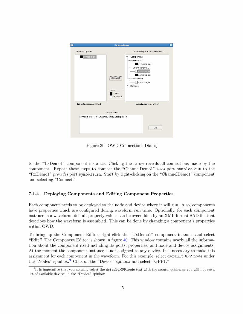
Figure 39: OWD Connections Dialog
to the “TxDemo1” component instance. Clicking the arrow reveals all connections made by thecomponent. Repeat these steps to connect the “ChannelDemo1” uses port samples out to the“RxDemo1” provides port symbols in. Start by right-clicking on the “ChannelDemo1” componentand selecting “Connect.”
7.1.4 Deploying Components and Editing Component Properties
Each component needs to be deployed to the node and device where it will run. Also, componentshave properties which are configured during waveform run time. Optionally, for each componentinstance in a waveform, default property values can be overridden by an XML-format SAD file thatdescribes how the waveform is assembled. This can be done by changing a component’s propertieswithin OWD.
To bring up the Component Editor, right-click the “TxDemo1” component instance and select“Edit.” The Component Editor is shown in figure 40. This window contains nearly all the informa-tion about the component itself including its ports, properties, and node and device assignments.At the moment the component instance is not assigned to any device. It is necessary to make thisassignment for each component in the waveform. For this example, select default GPP node underthe “Nodes” spinbox.3 Click on the “Device” spinbox and select “GPP1.”
3It is imperative that you actually select the default GPP node text with the mouse, otherwise you will not see alist of available devices in the “Device” spinbox
45
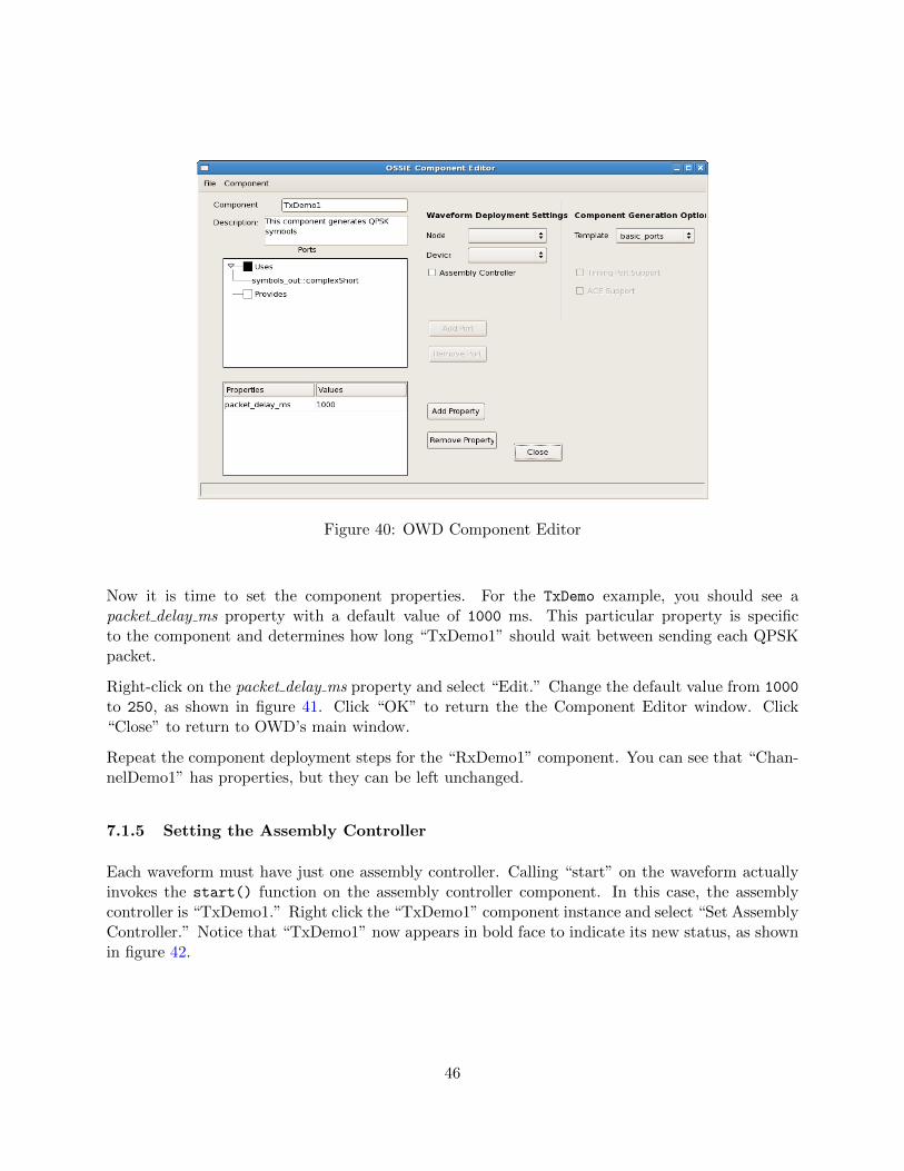
Figure 40: OWD Component Editor
Now it is time to set the component properties. For the TxDemo example, you should see apacket delay ms property with a default value of 1000 ms. This particular property is specificto the component and determines how long “TxDemo1” should wait between sending each QPSKpacket.
Right-click on the packet delay ms property and select “Edit.” Change the default value from 1000
to 250, as shown in figure 41. Click “OK” to return the the Component Editor window. Click“Close” to return to OWD’s main window.
Repeat the component deployment steps for the “RxDemo1” component. You can see that “Chan-nelDemo1” has properties, but they can be left unchanged.
7.1.5 Setting the Assembly Controller
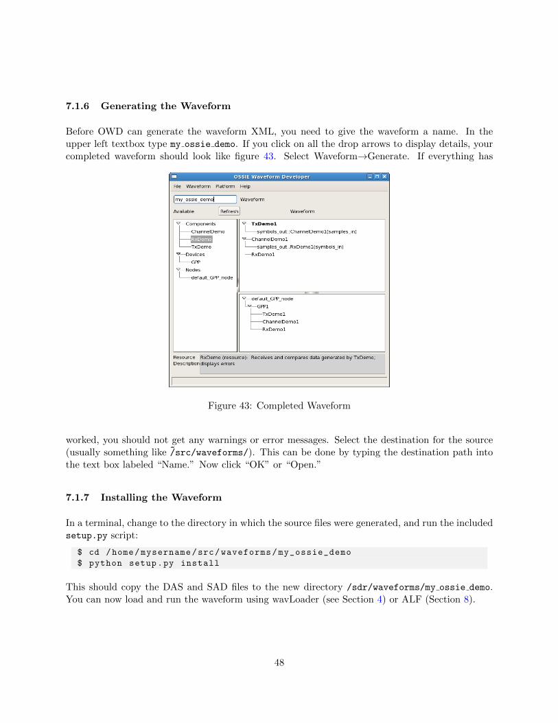
Each waveform must have just one assembly controller. Calling “start” on the waveform actuallyinvokes the start() function on the assembly controller component. In this case, the assemblycontroller is “TxDemo1.” Right click the “TxDemo1” component instance and select “Set AssemblyController.” Notice that “TxDemo1” now appears in bold face to indicate its new status, as shownin figure 42.
46
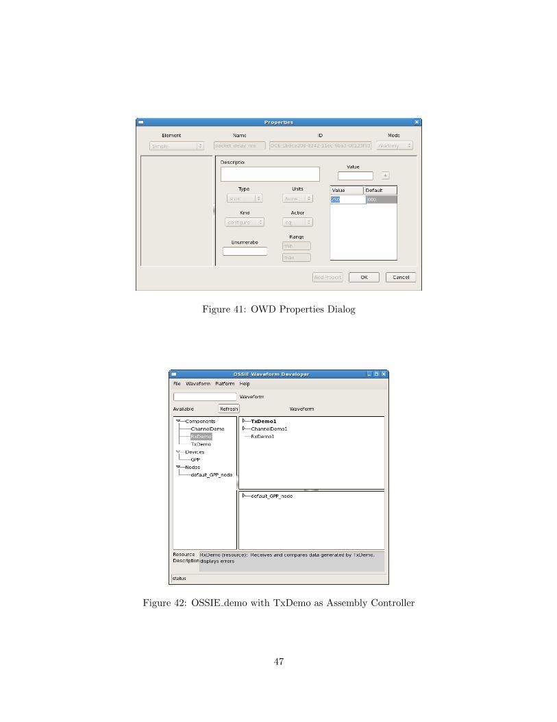
Figure 41: OWD Properties Dialog
Figure 42: OSSIE demo with TxDemo as Assembly Controller
47
7.1.6 Generating the Waveform
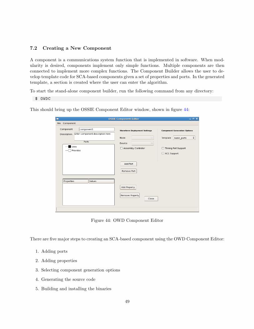
Before OWD can generate the waveform XML, you need to give the waveform a name. In theupper left textbox type my ossie demo. If you click on all the drop arrows to display details, yourcompleted waveform should look like figure 43. Select Waveform→Generate. If everything has
Figure 43: Completed Waveform
worked, you should not get any warnings or error messages. Select the destination for the source(usually something like ~/src/waveforms/). This can be done by typing the destination path intothe text box labeled “Name.” Now click “OK” or “Open.”
7.1.7 Installing the Waveform
In a terminal, change to the directory in which the source files were generated, and run the includedsetup.py script:
$ cd /home/mysername/src/waveforms/my_ossie_demo
$ python setup.py install
This should copy the DAS and SAD files to the new directory /sdr/waveforms/my ossie demo.You can now load and run the waveform using wavLoader (see Section 4) or ALF (Section 8).
48
7.2 Creating a New Component
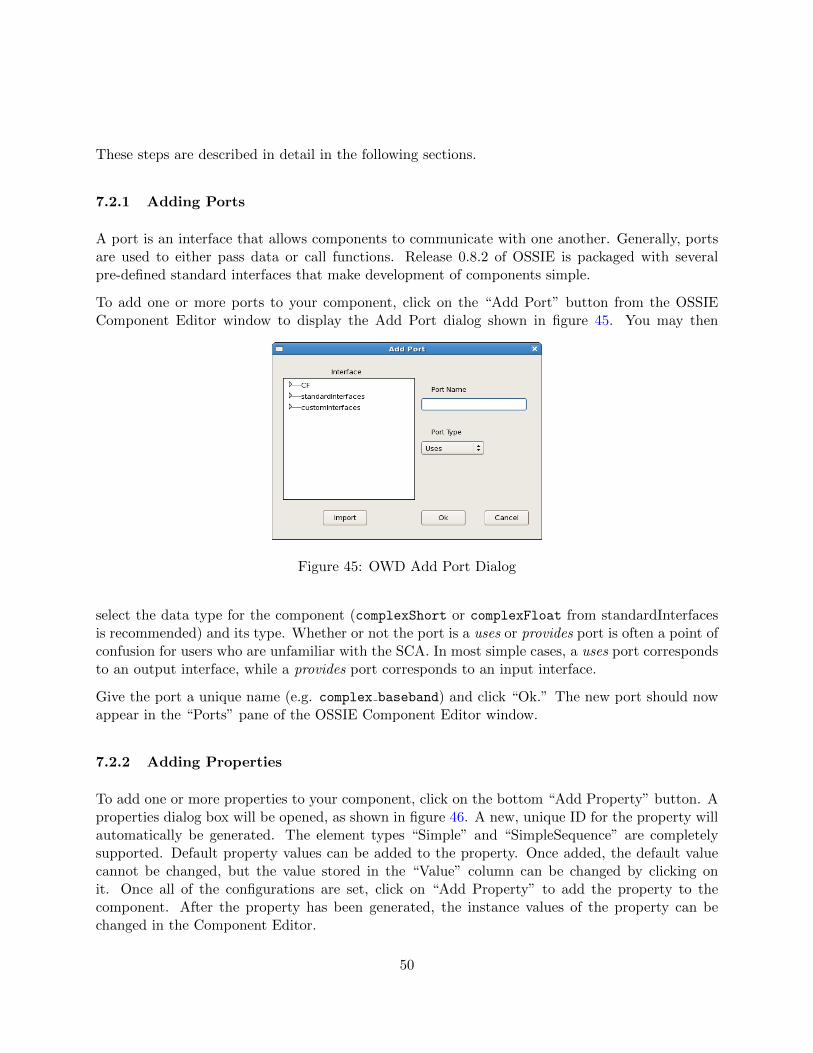
A component is a communications system function that is implemented in software. When mod-ularity is desired, components implement only simple functions. Multiple components are thenconnected to implement more complex functions. The Component Builder allows the user to de-velop template code for SCA-based components given a set of properties and ports. In the generatedtemplate, a section is created where the user can enter the algorithm.
To start the stand-alone component builder, run the following command from any directory:
$ OWDC
This should bring up the OSSIE Component Editor window, shown in figure 44:
Figure 44: OWD Component Editor
There are five major steps to creating an SCA-based component using the OWD Component Editor:
1. Adding ports
2. Adding properties
3. Selecting component generation options
4. Generating the source code
5. Building and installing the binaries
49
These steps are described in detail in the following sections.
7.2.1 Adding Ports
A port is an interface that allows components to communicate with one another. Generally, portsare used to either pass data or call functions. Release 0.8.2 of OSSIE is packaged with severalpre-defined standard interfaces that make development of components simple.
To add one or more ports to your component, click on the “Add Port” button from the OSSIEComponent Editor window to display the Add Port dialog shown in figure 45. You may then
Figure 45: OWD Add Port Dialog
select the data type for the component (complexShort or complexFloat from standardInterfacesis recommended) and its type. Whether or not the port is a uses or provides port is often a point ofconfusion for users who are unfamiliar with the SCA. In most simple cases, a uses port correspondsto an output interface, while a provides port corresponds to an input interface.
Give the port a unique name (e.g. complex baseband) and click “Ok.” The new port should nowappear in the “Ports” pane of the OSSIE Component Editor window.
7.2.2 Adding Properties
To add one or more properties to your component, click on the bottom “Add Property” button. Aproperties dialog box will be opened, as shown in figure 46. A new, unique ID for the property willautomatically be generated. The element types “Simple” and “SimpleSequence” are completelysupported. Default property values can be added to the property. Once added, the default valuecannot be changed, but the value stored in the “Value” column can be changed by clicking onit. Once all of the configurations are set, click on “Add Property” to add the property to thecomponent. After the property has been generated, the instance values of the property can bechanged in the Component Editor.
50
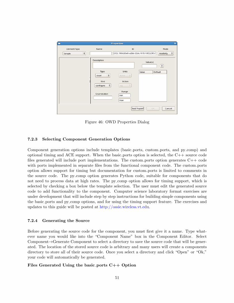
Figure 46: OWD Properties Dialog
7.2.3 Selecting Component Generation Options
Component generation options include templates (basic ports, custom ports, and py comp) andoptional timing and ACE support. When the basic ports option is selected, the C++ source codefiles generated will include port implementations. The custom ports option generates C++ codewith ports implemented in separate files from the functional component code. The custom portsoption allows support for timing but documentation for custom ports is limited to comments inthe source code. The py comp option generates Python code, suitable for components that donot need to process data at high rates. The py comp option allows for timing support, which isselected by checking a box below the template selection. The user must edit the generated sourcecode to add functionality to the component. Computer science laboratory format exercises areunder development that will include step by step instructions for building simple components usingthe basic ports and py comp options, and for using the timing support feature. The exercises andupdates to this guide will be posted at http://ossie.wireless.vt.edu.
7.2.4 Generating the Source
Before generating the source code for the component, you must first give it a name. Type what-ever name you would like into the “Component Name” box in the Component Editor. SelectComponent→Generate Component to select a directory to save the source code that will be gener-ated. The location of the stored source code is arbitrary and many users will create a componentsdirectory to store all of their source code. Once you select a directory and click “Open” or “Ok,”your code will automatically be generated.
Files Generated Using the basic ports C++ Option
51
configure.ac This is the script that autoconf [1] uses to generate the configure file. It checksfor dependencies such as which compiler to use, as well as the presence of OSSIE libraries.
Makefile.am This is the script that automake [2] uses to generate the Makefile. It includes allthe source files for the component.
reconf This is a script to run the automake tools.
MyComponent.h Component class header file
MyComponent.cpp Component class implementation definition
main.cpp Contains the mandatory int main() definition
MyComponent.prf.xml Component property file
MyComponent.scd.xml Software component descriptor
MyComponent.spd.xml Software package descriptor
documentation.txt File for documenting your component
Doxyfile Doxygen [3] file for generating documentation
Files Generated Using py comp Option
MyComponent.py Python file with port implementations
WorkModule.py Python file where processing is done
setup.py Install script used to copy Python and XML files into the appropriate subdirectoriesunder /sdr once the component is edited to provide functionality. This is executed by typingpython setup.py install
MyComponent.prf.xml, MyComponent.scd.xml, MyComponent.spd.xml Same as forC++ components
7.2.5 Building a Working Python Component
Generated component template code must be modified to process data. The instructions here applyto a very basic Python component with one uses and one provides port and no properties. Propertyvalues can be used in the processing operations, but this will be the subject of a future exercise.
All data coming into a provides port will be loaded into the WorkModule buffer. The data goinginto this buffer will be loaded into variables called I and Q. See the generated WorkModule.py andlook for:
I = new_data [0]
Q = new_data [1]
52
This implies that if you try to run a component that is getting real data only, Q should be empty,and this may even cause an error. There are comments in various parts of the python files describinghow to adjust your code appropriately.
The next two lines initialize two arrays to store your new data:
newI = [0 for x in range(len(I)))]
newQ = [0 for x in range(len(Q)))]
Following these lines are comments with an example of how to process data. If you uncommentthe 3-line example, your component will pass the data received by the provides (input) port to theuses (output) port, assuming you have one uses port of type complexShort and one provides port,also of type complexShort. Code can be added to process the data.
The next set of lines following the comment “# Output the new data,” will send the newI andnewQ vectors to all of your output ports.
7.2.6 Editing the SPD File
You will need to edit MyComponent.spd.xml before your Python component will work properly.Find the XML tag below the tag <code type="Executable". By default the next tag is:
<localfile name="bin/MyComponent "/>}
This needs to be changed to:
<localfile name="bin/MyComponent/MyComponent.py"/>
7.2.7 Making Sure Files are Executable
After you have installed the component (see below), you will need to make sure that you havepermission to execute the Python files. To do this, navigate to /sdr/bin/MyComponent and type:
$ chmod +x *.py
C++ components
For C++ components, within the generated your component name.cpp file you may enter thecode for processing data. Look for /*insert code here to do work*/ within the process datafunction. Editing the SPD file should not be necessary. The installed executable file,/sdr/bin/your component name, needs to be executable, but this should be done by default.
7.2.8 Building and Installing the Binaries
Once the component has been generated, use a terminal to navigate to the directory of the createdsource code (e.g. src/components). Four commands must be executed (in order) in order to
53
install a C++ component to the /sdr directory:
$ ./ reconf
$ ./ configure
$ make
$ make install
If you do not have ownership of your target install directory, (by default /sdr), you will need torun make install as root.
To install a Python component, from the directory that contains the generated and edited sourcecode, simply execute the following command:
$ python setup.py install
Just as with the C++ installation, if you do not have ownership of your target install directoryyou will need to run python setup.py install with root privileges.
7.3 Custom License Generation
OWD allows for customization of the license headers that proceed component or waveform sourcefiles. By changing some simple parameters, these licenses can be tailored to a specific need.
The configuration file that must be modified to customize the header istools/WaveDev/wavedev.cfg. There are multiple XML tags within this file, but the three thatneed to be considered are sourcepreamble, licensefile, and developer.
The user will need to configure this header, as a meaningful default header will not be used. Bydefault, the license header will display as:
Copyright $YEAR by __DEVELOPER__ , all rights reserved.
The developer option is simply the name of the person(s), company, or organization to whom thefile should be copywritten. The sourcepreamble option should contain an absolute path to a file(readable by the user) that contains the preamble to be placed at the top of all source files. Thesourcepreamble file is parsed as follows:
COMP NAME is replaced with the name of the component or waveform, YEAR is re-placed with the current year, and DEVELOPER is replaced with the developer value fromwavedev.cfg file. Finally, licensefile is an absolute path to a full license file (e.g. the GPL)that will accompany the generated component or waveform.
54
7.4 Removing Components, Devices, Nodes and Waveforms
7.4.1 Removal Notes
The files that need to be removed all exist within the /sdr directory. To remove a componentor device, the executable must be removed from /sdr/dom/bin/ (components) or /sdr/dev/bin
(devices) as well as the xml files in /sdr/dom/xml/ (components) or /sdr/dev/xml (devices). Toremove a node the xml files must be removed from /sdr/dev/nodes/, and to remove a waveformthe xml files must be removed from /sdr/dom/waveforms/. The following steps will walk throughthe procedure required to uninstall a component or device, a node and a waveform.
7.4.2 Component and Device Removal
Files in both bin and xml directories must be deleted to uninstall a component or a device. Moveinto the bin directory.
$ cd /sdr/dom/bin
or
$ cd /sdr/dev/bin
\end{listlisting}
Now delete the executable. The file is write protected , so the {\tt -f} option will
not ask you to verify that you want to delete the file.
\begin{lstlisting }[]
$ rm -f COMPONENT_OR_DEVICE_NAME
Now move into the xml/ directory.
$ cd ../xml/
Remove the directory containing all of the xml files. This command must be executed as root,however exit out of root after the folder has been removed.
# rm -rf COMPONENT_OR_DEVICE_NAME
# exit
The component has now been removed. Open OWD to verify the component is no longer available.
$ OWD
Within OWD, click the arrow next to Components if you are removing a component, or Devices
if you are removing a device, in the left pane. Verify that the component is no longer listed. IfOWD was running while the component or device was removed, click the Refresh button abovethe component list to refresh the list of available components and devices.
55
7.4.3 Node Removal
To remove a node only a single directory within /sdr/dev/nodes/ needs to be removed. Move intothe nodes/ directory.
$ cd /sdr/dev/nodes/
Remove the directory containing the xml files. This must be done as root, however exit out of rootafter entering the command.
# rm -rf NODE_NAME
# exit
The node has now been removed. Open OWD to verify the node is no longer available.
$ OWD
Within OWD, click the arrow next to Nodes in the left pane. Verify that the node is no longerlisted. If OWD was running while the node was removed, click the Refresh button above thecomponent list to refresh the list of available nodes.
7.4.4 Waveform Removal
To remove a waveform, only a single directory within /sdr/dom/waveforms/ needs to be removed.
To remove a waveform, first move into the waveforms/ directory.
$ cd /sdr/dom/waveforms/
Remove the directory containing the xml files. This should not be done as root.
$ rm -rf WAVEFORM_NAME
The waveform has now been removed.
56
8 ALF Graphical Debugging Environment
Our waveform application visualization and debugging environment, ALF, provides a graphical userinterface for waveform management and debugging. Not only is it useful for installing and startingwaveforms, but it also provides a selection of debugging tools. When a waveform is running, thedeveloper is able to monitor the throughput of components, plot data in real time, and input oroutput data to components in a waveform. ALF also gives the user the ability to run componentsthat are not part of a host waveform in the framework.
8.1 Running ALF
To start ALF, nodeBooter must be started as usual. In one tab or terminal type:
$ nodeBooter -D -d dev/nodes/default_GPP_node/DeviceManager.dcd.xml
default GPP node can be changed if your waveform requires it.
Once nodeBooter is running, open a second tab or terminal and type:
$ ALF
This should open the ALF main window without errors or warnings, as shown in figure 47. Youwill be presented with a dialog box to select the IP address hosting the NameService. If you arerunning the NameService locally (i.e. 127.0.0.1), then select ’OK’ and continue using ALF. Youcan also point ALF to a different IP address that is hosting the NameService, for example, anembedded platform.
8.1.1 Specifying Naming Service IP address
To specify a different address for the naming service, append the following to ALF on the commandline:-ORBInitRef NameService=corbaname::<IP Address of Naming Service>
$ ALF -ORBInitRef NameService=corbaname ::<IP Address of Naming Service >
Alternatively, once ALF is running, the IP address of the Naming Service can be changed by clickingthe Select Naming Service button in the toolbar, as shown in figure 48.
This will bring up the Target Naming Service Selector dialog, shown in figure 49. Then enter theaddress in the Network Host field and click Apply.
57
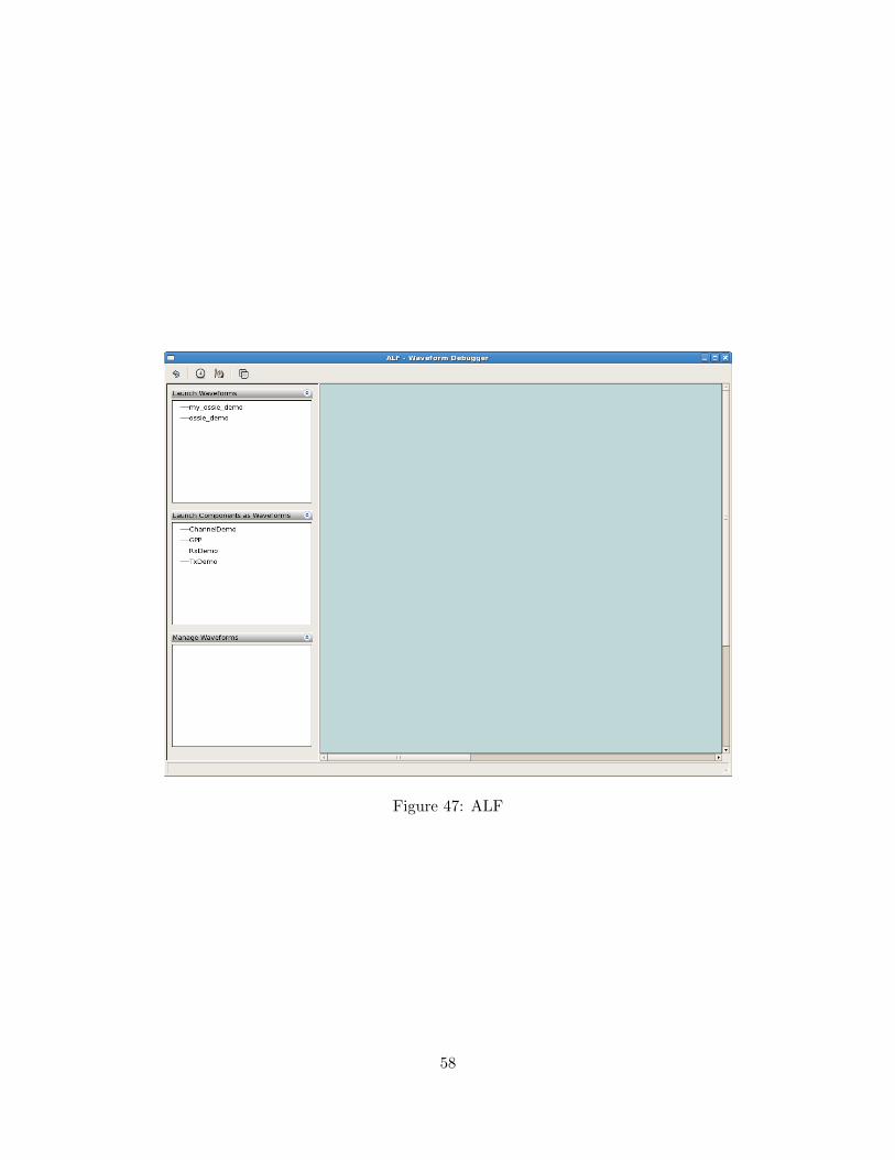
Figure 47: ALF
58
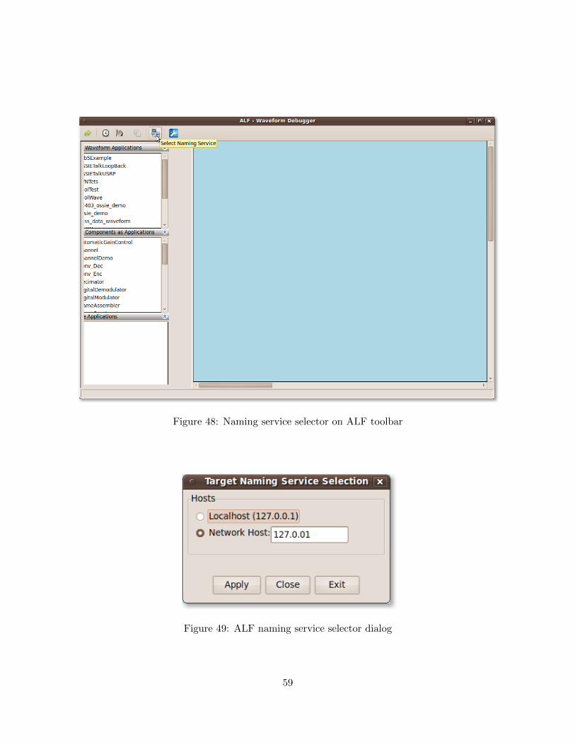
Figure 48: Naming service selector on ALF toolbar
Figure 49: ALF naming service selector dialog
59
8.2 Running Waveforms
The top left pane, Launch Waveform Applications, displays a list of installed waveforms. Toinstall and run an instance of the waveform, simply double-click on the waveform name.4 Theterminal in which nodeBooter was started should display the output of the OSSIE frameworksApplicationFactory as it installs the waveform. You may easily run multiple waveforms, or multipleinstances of the same waveform in this manner.
It is also possible to install a waveform and start it manually. In the Launch Waveform Applicationswindow, right click on a waveform to select Install or Install and Start. If Install is selected, thewaveform will be installed and will be visible in the Manage Applications window. To start theinstalled waveform, right click and select start. To stop the waveform, right click on stop.
8.2.1 Running components as Waveforms
ALF has the ability to run individual components as waveforms. Available components are listedin the second window on the left side of ALF and can be installed and started just like waveforms.Note however that this feature is only available if ALF was run on the same machine as the namingservice.
8.3 Managing Running Waveforms
The Manage Applications pane in the lower-left corner of the main ALF window displays a lists ofall instances of running waveforms. Try running the ossie demo waveform using the instructionsabove. You should see –OSSIE::ossie demo 1 listed in the Manage Waveforms pane. Double-click on–OSSIE::ossie demo 1 to display the waveform’s components in the main window, shown in figure50. Notice that –OSSIE::ossie demo 1 is now in bold face to indicate that this waveform instance isthe one currently being displayed.
8.3.1 Refreshing the ALF display
To reload the system waveforms and active waveforms available on the system, press the refreshbutton (green arrow) in the ALF toolbar.
8.4 ALF Tools
ALF uses a set of tools (or plugins) to assist in waveform and component development. To see alist of available tools, display a waveform and right-click on one of the ports. See figure 51.
4Note that for a waveform to run, you must have started the correct node for that particular waveform in node-Booter. For a resource to run, you must have started one of the default nodes in nodeBooter
60
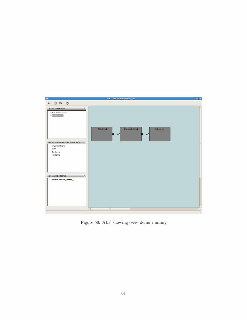
Figure 50: ALF showing ossie demo running
61
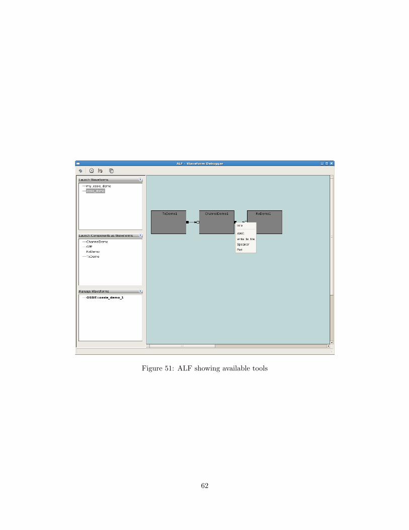
Figure 51: ALF showing available tools
62
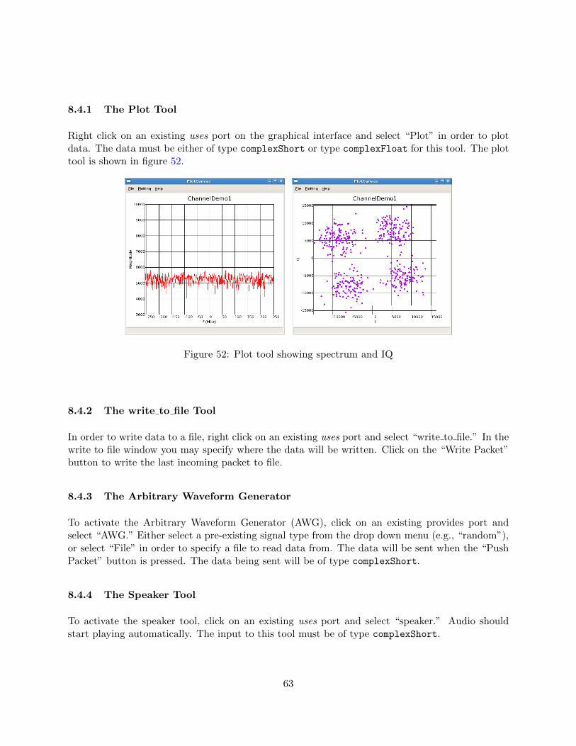
8.4.1 The Plot Tool
Right click on an existing uses port on the graphical interface and select “Plot” in order to plotdata. The data must be either of type complexShort or type complexFloat for this tool. The plottool is shown in figure 52.
Figure 52: Plot tool showing spectrum and IQ
8.4.2 The write to file Tool
In order to write data to a file, right click on an existing uses port and select “write to file.” In thewrite to file window you may specify where the data will be written. Click on the “Write Packet”button to write the last incoming packet to file.
8.4.3 The Arbitrary Waveform Generator
To activate the Arbitrary Waveform Generator (AWG), click on an existing provides port andselect “AWG.” Either select a pre-existing signal type from the drop down menu (e.g., “random”),or select “File” in order to specify a file to read data from. The data will be sent when the “PushPacket” button is pressed. The data being sent will be of type complexShort.
8.4.4 The Speaker Tool
To activate the speaker tool, click on an existing uses port and select “speaker.” Audio shouldstart playing automatically. The input to this tool must be of type complexShort.
63
8.4.5 The Timing Tool
The main toolbar of the ALF display contains buttons that allow you to toggle the timing displays.In order to view the throughput of a port, right click on the desired port and select “Get Info.”Note that the port must support timing. This feature can be added when creating the compo-nent. Timing support is available only for the custom ports and py comp component generationoptions. Currently no documentation exists for the custom ports option beyond the comments inthe generated source code, so it is recommended for advanced developers only.
8.4.6 The Connect Tool
On the main toolbar of the ALF display, to the right of the timing buttons, there is a button tostart the connect tool. To connect two ports, specify the uses port on the left half of the connecttool display and specify the provides port on the right side of the connect tool display. To specifya port, select the appropriate waveform from the first drop-down menu. Once the waveform isselected, the second drop-down menu will allow you to select a component. Once the componentis selected, select the name of the port you wish to connect in the drop-down men below thecomponent selected. Once both the uses and provides port have been selected, press the “Connect”button.
8.4.7 The Automation Tool
The Automation Tool is a feature which allows aggregate waveforms to be built. Through theuse of XML files, additional components can be added or removed while the waveform is run-ning. To start the tool, select the “Connect Tool” button on the main toolbar within ALF.This will display the Connect Tool window, which at the bottom has a path to an automationfile and a “Load Automation File” button. Double click on a waveform in the Launch Wave-form Applications panel in the main ALF window to start the waveform. Browse to the XMLfile and select“ Load Automation File.” For example, to run the pass data waveform, browse to/usr/lib/python2.5/site-packages/alf/config/example1.xml, then select “Load AutomationFile.”
This will bring up the Arbitrary Waveform Generator window. The AWG allows components tobe added to the waveform through the Packet Headers box, and determines which kind of datawill be sent to the components. In this example, the waveform has two consumers, labeled 1 and2. These are components which can be installed and uninstalled through setting the appropriatepacket headers. To send a packet to a consumer enter its number into the Packet Headers box,separated by commas. For example, to send two packets to consumer 1, and one to consumer 2,enter the following:
1, 1, 2
64
To uninstall a consumer, enter a negative sign before the consumer number. For example, to sendthree packets to consumer 1 and then uninstall it, enter:
1, 1, 1, -1
By selecting Push Packet at the bottom, a single packet will be pushed to the correspondingconsumer listed in the Packet Headers box. Each time the button is selected, it will advance tothe next consumer listed and when it reaches the end of the list it will loop back to the beginning.Selecting the Start button sends the sequence continually until the Stop button is selected.
8.4.8 Automation XML File
The Automation Tool determines which components are available to be installed. The XML filelists producers and consumers, which provide and consume packets, respectively. The XML filealso defines the names of the producers and consumers, what their number designation is, whenthey are installed, which waveform they are assigned to, the name of the component and the inputor output port. For example, in example1.xml:
<consumer >
<name >My first consumer </name >
<header >1</header >
<install_at_startup >True </ install_at_startup >
<waveform >pass_data_waveform </waveform >
<componentInstance >pass_data </ componentInstance >
<port >cshort_in </port >
The name of the consumer is “My first consumer” and it is designated 1, which means to send apacket to the consumer using the AWG the number 1 must be entered in the Packet Headers textbox. The consumer is set to be installed at start up, denoted by the install at startup tag. If thiswas set as False, the consumer would only be installed when the first packet is pushed to it. Thecomponent is pass data, and the input port is defined as cshort in.
65
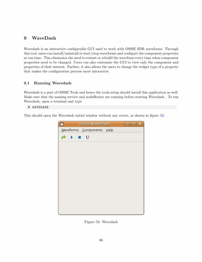
9 WaveDash
Wavedash is an interactive configurable GUI used to work with OSSIE SDR waveforms. Throughthis tool, users can install/uninstall or start/stop waveforms and configure the component propertiesat run time. This eliminates the need to restart or rebuild the waveform every time when componentproperties need to be changed. Users can also customize the GUI to view only the component andproperties of their interest. Further, it also allows the users to change the widget type of a propertythat makes the configuration process more interactive.
9.1 Running Wavedash
Wavedash is a part of OSSIE Tools and hence the tools setup should install this application as well.Make sure that the naming service and nodeBooter are running before starting Wavedash . To runWavedash, open a terminal and type
$ WAVEDASH
This should open the Wavedash initial window without any errors, as shown in figure 53.
Figure 53: Wavedash
66
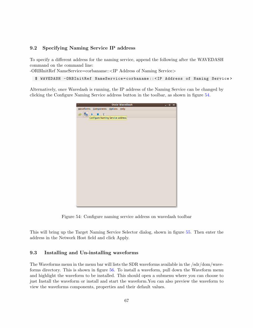
9.2 Specifying Naming Service IP address
To specify a different address for the naming service, append the following after the WAVEDASHcommand on the command line:-ORBInitRef NameService=corbaname::<IP Address of Naming Service>
$ WAVEDASH -ORBInitRef NameService=corbaname ::<IP Address of Naming Service >
Alternatively, once Wavedash is running, the IP address of the Naming Service can be changed byclicking the Configure Naming Service address button in the toolbar, as shown in figure 54.
Figure 54: Configure naming service address on wavedash toolbar
This will bring up the Target Naming Service Selector dialog, shown in figure 55. Then enter theaddress in the Network Host field and click Apply.
9.3 Installing and Un-installing waveforms
The Waveforms menu in the menu bar will lists the SDR waveforms available in the /sdr/dom/wave-forms directory. This is shown in figure 56. To install a waveform, pull down the Waveform menuand highlight the waveform to be installed. This should open a submenu where you can choose tojust Install the waveform or install and start the waveform.You can also preview the waveform toview the waveforms components, properties and their default values.
67
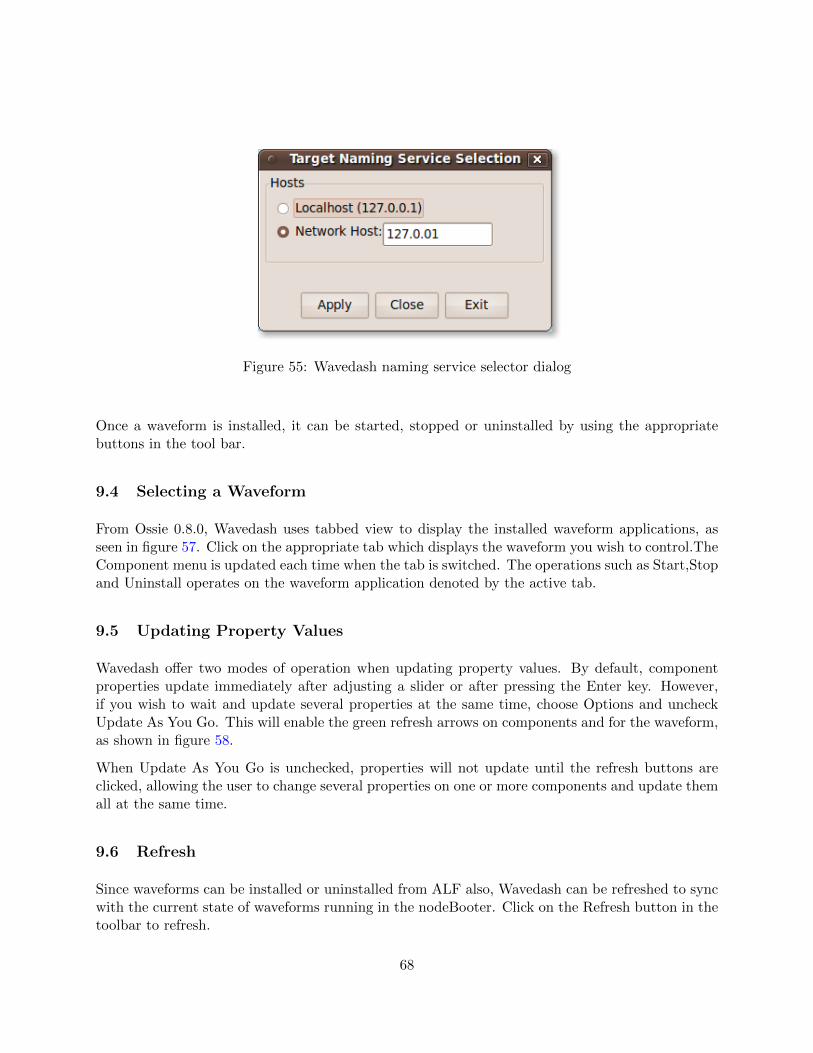
Figure 55: Wavedash naming service selector dialog
Once a waveform is installed, it can be started, stopped or uninstalled by using the appropriatebuttons in the tool bar.
9.4 Selecting a Waveform
From Ossie 0.8.0, Wavedash uses tabbed view to display the installed waveform applications, asseen in figure 57. Click on the appropriate tab which displays the waveform you wish to control.TheComponent menu is updated each time when the tab is switched. The operations such as Start,Stopand Uninstall operates on the waveform application denoted by the active tab.
9.5 Updating Property Values
Wavedash offer two modes of operation when updating property values. By default, componentproperties update immediately after adjusting a slider or after pressing the Enter key. However,if you wish to wait and update several properties at the same time, choose Options and uncheckUpdate As You Go. This will enable the green refresh arrows on components and for the waveform,as shown in figure 58.
When Update As You Go is unchecked, properties will not update until the refresh buttons areclicked, allowing the user to change several properties on one or more components and update themall at the same time.
9.6 Refresh
Since waveforms can be installed or uninstalled from ALF also, Wavedash can be refreshed to syncwith the current state of waveforms running in the nodeBooter. Click on the Refresh button in thetoolbar to refresh.
68
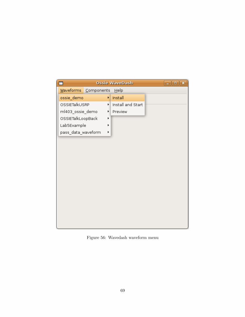
Figure 56: Wavedash waveform menu
69
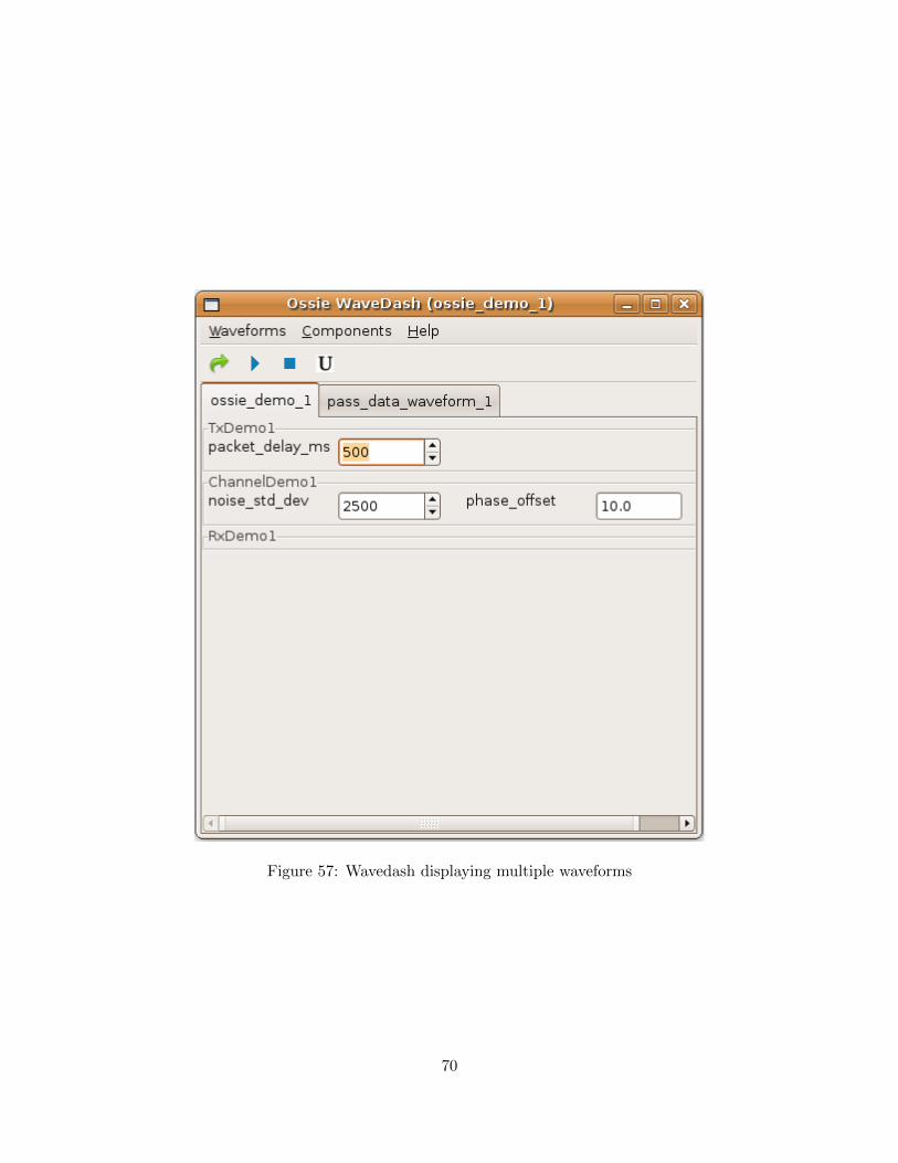
Figure 57: Wavedash displaying multiple waveforms
70
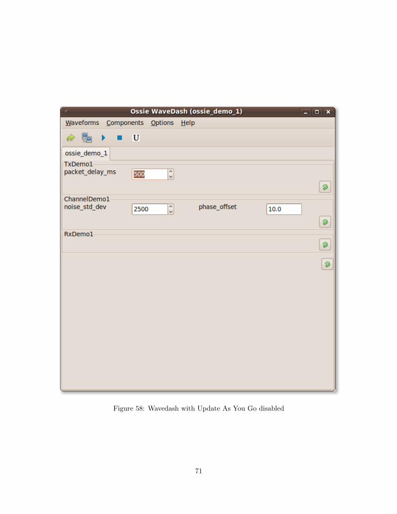
Figure 58: Wavedash with Update As You Go disabled
71
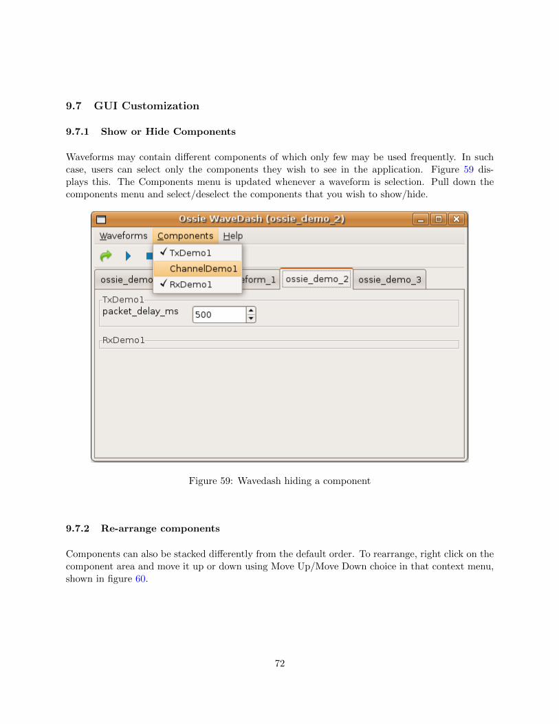
9.7 GUI Customization
9.7.1 Show or Hide Components
Waveforms may contain different components of which only few may be used frequently. In suchcase, users can select only the components they wish to see in the application. Figure 59 dis-plays this. The Components menu is updated whenever a waveform is selection. Pull down thecomponents menu and select/deselect the components that you wish to show/hide.
Figure 59: Wavedash hiding a component
9.7.2 Re-arrange components
Components can also be stacked differently from the default order. To rearrange, right click on thecomponent area and move it up or down using Move Up/Move Down choice in that context menu,shown in figure 60.
72
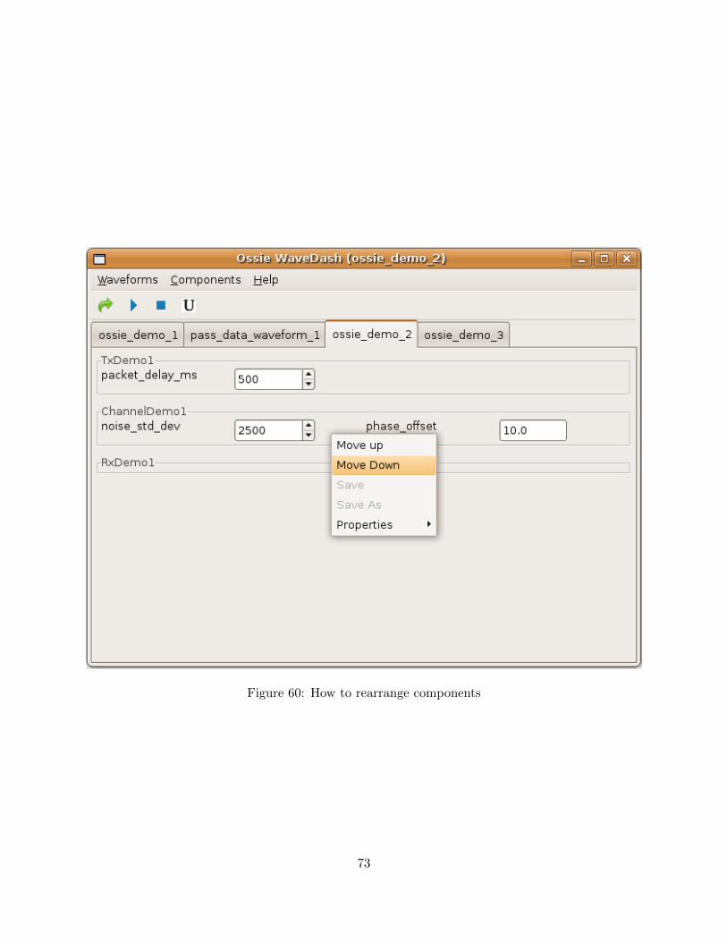
Figure 60: How to rearrange components
73
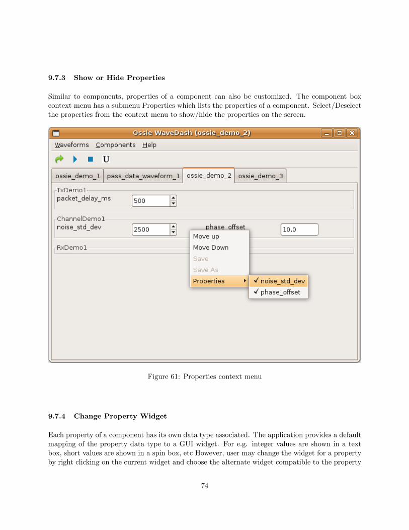
9.7.3 Show or Hide Properties
Similar to components, properties of a component can also be customized. The component boxcontext menu has a submenu Properties which lists the properties of a component. Select/Deselectthe properties from the context menu to show/hide the properties on the screen.
Figure 61: Properties context menu
9.7.4 Change Property Widget
Each property of a component has its own data type associated. The application provides a defaultmapping of the property data type to a GUI widget. For e.g. integer values are shown in a textbox, short values are shown in a spin box, etc However, user may change the widget for a propertyby right clicking on the current widget and choose the alternate widget compatible to the property
74
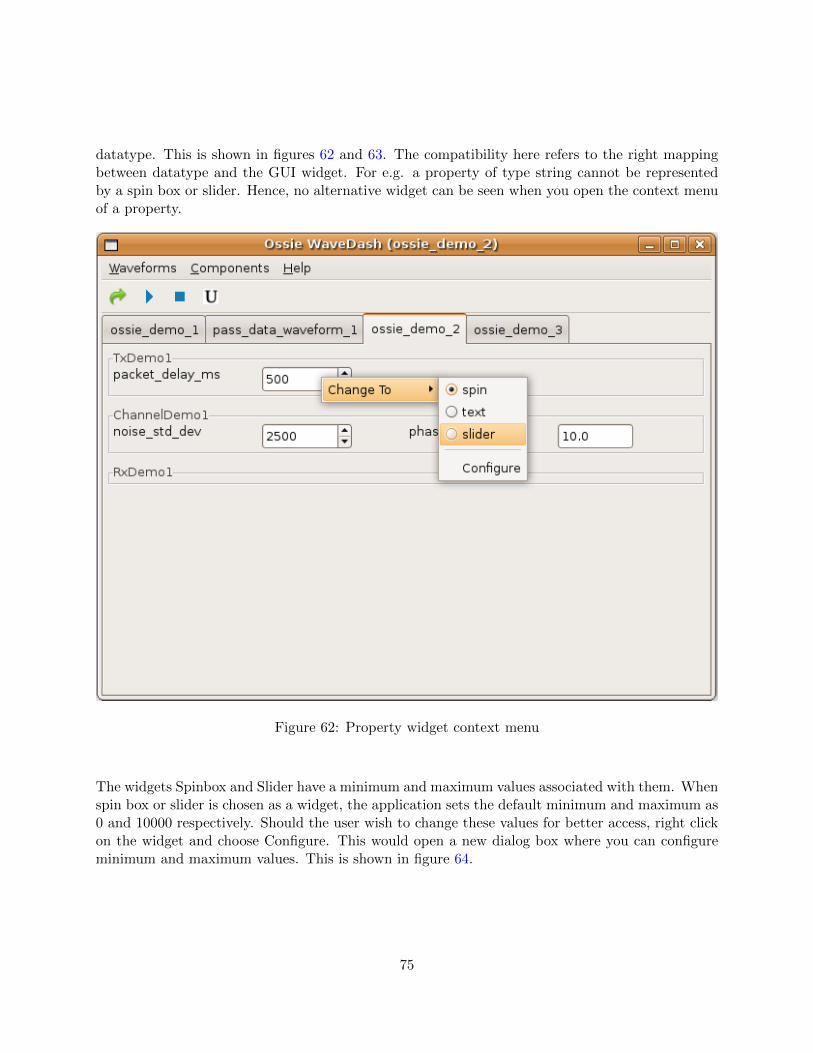
datatype. This is shown in figures 62 and 63. The compatibility here refers to the right mappingbetween datatype and the GUI widget. For e.g. a property of type string cannot be representedby a spin box or slider. Hence, no alternative widget can be seen when you open the context menuof a property.
Figure 62: Property widget context menu
The widgets Spinbox and Slider have a minimum and maximum values associated with them. Whenspin box or slider is chosen as a widget, the application sets the default minimum and maximum as0 and 10000 respectively. Should the user wish to change these values for better access, right clickon the widget and choose Configure. This would open a new dialog box where you can configureminimum and maximum values. This is shown in figure 64.
75
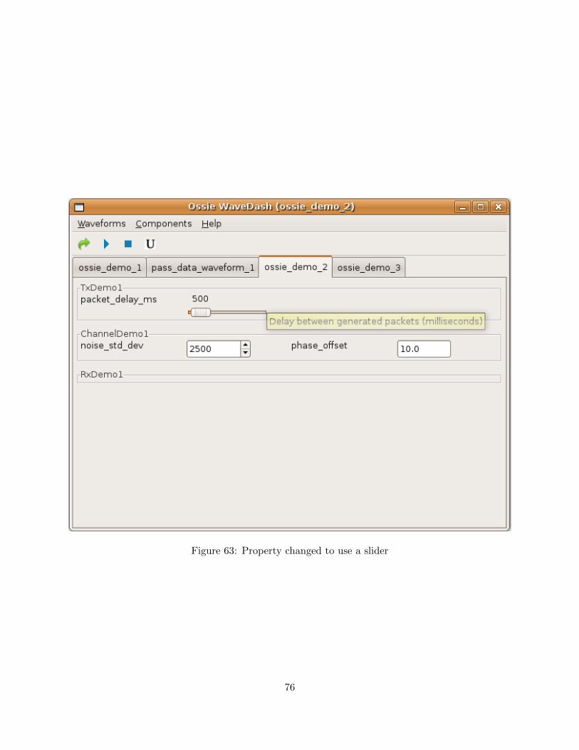
Figure 63: Property changed to use a slider
76
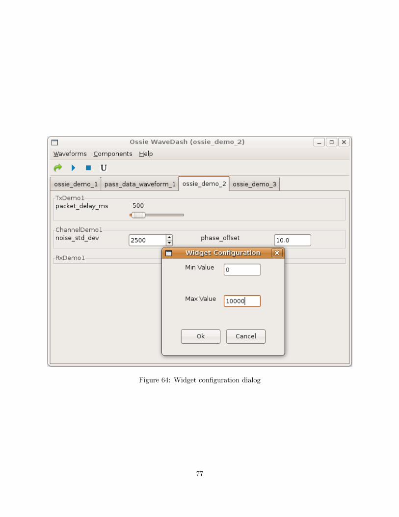
Figure 64: Widget configuration dialog
77
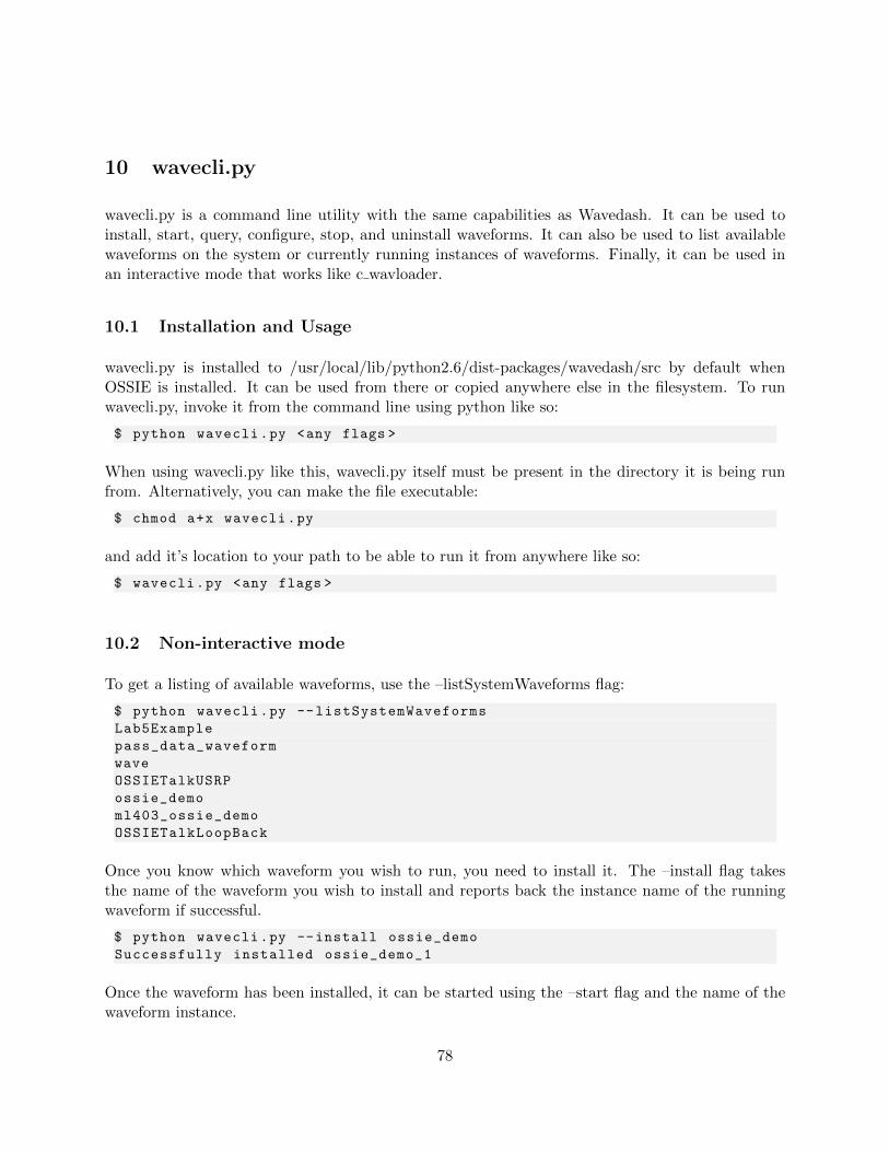
10 wavecli.py
wavecli.py is a command line utility with the same capabilities as Wavedash. It can be used toinstall, start, query, configure, stop, and uninstall waveforms. It can also be used to list availablewaveforms on the system or currently running instances of waveforms. Finally, it can be used inan interactive mode that works like c wavloader.
10.1 Installation and Usage
wavecli.py is installed to /usr/local/lib/python2.6/dist-packages/wavedash/src by default whenOSSIE is installed. It can be used from there or copied anywhere else in the filesystem. To runwavecli.py, invoke it from the command line using python like so:
$ python wavecli.py <any flags >
When using wavecli.py like this, wavecli.py itself must be present in the directory it is being runfrom. Alternatively, you can make the file executable:
$ chmod a+x wavecli.py
and add it’s location to your path to be able to run it from anywhere like so:
$ wavecli.py <any flags >
10.2 Non-interactive mode
To get a listing of available waveforms, use the –listSystemWaveforms flag:
$ python wavecli.py --listSystemWaveforms
Lab5Example
pass_data_waveform
wave
OSSIETalkUSRP
ossie_demo
ml403_ossie_demo
OSSIETalkLoopBack
Once you know which waveform you wish to run, you need to install it. The –install flag takesthe name of the waveform you wish to install and reports back the instance name of the runningwaveform if successful.
$ python wavecli.py --install ossie_demo
Successfully installed ossie_demo_1
Once the waveform has been installed, it can be started using the –start flag and the name of thewaveform instance.
78
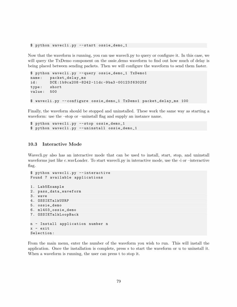
$ python wavecli.py --start ossie_demo_1
Now that the waveform is running, you can use wavecli.py to query or configure it. In this case, wewill query the TxDemo component on the ossie demo waveform to find out how much of delay isbeing placed between sending packets. Then we will configure the waveform to send them faster.
$ python wavecli.py --query ossie_demo_1 TxDemo1
name: packet_delay_ms
id: DCE:1b9ca208 -8242 -11dc -9ba3 -00123 f63025f
type: short
value: 500
$ wavecli.py --configure ossie_demo_1 TxDemo1 packet_delay_ms 100
Finally, the waveform should be stopped and uninstalled. These work the same way as starting awaveform: use the –stop or –uninstall flag and supply an instance name.
$ python wavecli.py --stop ossie_demo_1
$ python wavecli.py --uninstall ossie_demo_1
10.3 Interactive Mode
Wavecli.py also has an interactive mode that can be used to install, start, stop, and uninstallwaveforms just like c wavLoader. To start wavecli.py in interactive mode, use the -i or –interactiveflag.
$ python wavecli.py --interactive
Found 7 available applications
1. Lab5Example
2. pass_data_waveform
3. wave
4. OSSIETalkUSRP
5. ossie_demo
6. ml403_ossie_demo
7. OSSIETalkLoopBack
n - Install application number n
x - exit
Selection:
From the main menu, enter the number of the waveform you wish to run. This will install theapplication. Once the installation is complete, press s to start the waveform or u to uninstall it.When a waveform is running, the user can press t to stop it.
79
11 WaveDash Server
OSSIE comes with a simple HTTP server that enables controlling a software radio from anycomputer with an internet connection. The server is still under development and so detailedinstructions are not yet available, but intrepid users may find it useful. The pertinent files areWavedashServer.py and WavedashHander.py which are installed to /usr/local/lib/python2.6/dist-packages/wavedash/src. The Handler listens to a specific port and passes commands it receives tothe Server that runs in the background and maintains a connection to the local naming service.
80
12 Uninstallation
12.1 Uninstalling OSSIE
To uninstall OSSIE, open a terminal and change into the directory where the originial OSSIE sourceor tarball was saved. From that directory, run
$sudo make uninstall
This will remove everything from /sdr, along with libraries installed by OSSIE. In addition, deletethe ossie folder under /usr/local/lib/python2.x/dist-packages.
12.2 Uninstalling Waveform Workshop
OWD, ALF, and Wavedash are all python tools that get installed under /usr/local/. The binariescan be found in /usr/local/bin, and the python source can be found in/usr/local/lib/python2.x/dist-packages.To uninstall them, simply delete ALF, WAVEDASH, OWD, and OWDC from /usr/local/bin, andthe alf, alf plugins, wavedash, and Wavedev folders from /usr/local/lib/python2.x/dist-packages.
OEF is installed separately into Eclipse so it must be installed from within Eclipse. From themenubar, choose Help : About Eclipse, then click on Installation Details. This will bring up theInstallation Details window, shown in figure 65.
Choose OSSIE Waveform Developer Feature, then click on Uninstall. Then follow the prompts tocomplete the uninstall process.
81
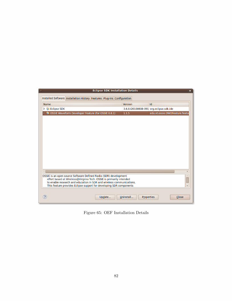
Figure 65: OEF Installation Details
82
13 Helping With Development
OSSIE is an open source project and we encourage everyone interested to contribute to the project.
13.1 Giving Feedback and Submitting Bugs
The ossie-discuss mailing list and the #ossie IRC channel on Freenode are probably the bestmethods of discussing and collaboratively solving end-user problems. For development-orientedissues, Trac tickets and the ossie-dev mailing list are probably best. See Section 2.2.4 for moreinformation on the IRC channel and Section 2.2.2 for details on the mailing lists.
13.2 Contributing Code
Contributions are heartily welcomed. The best way to get to know the developers and really getinvolved is submit patches that fix bugs or add features. Patches can generally be sent to us throughTrac or the mailing list. Write access to the subversion repository can be given to contributors whohave proved their reliability.
In order to make sure OSSIE stays open, we have licensed the source code under the GNU GeneralPublic License Version 2 and the Lesser General Public License. Contributions to the projectmust be made under these licenses. Also, the preferred coding style is that devised for the Linuxkernel [7]. See [4, 5] for more information about the licenses.
83
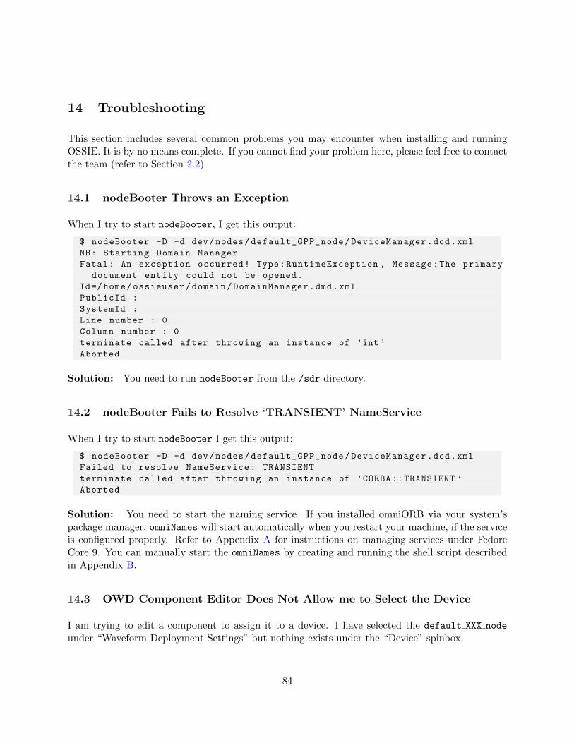
14 Troubleshooting
This section includes several common problems you may encounter when installing and runningOSSIE. It is by no means complete. If you cannot find your problem here, please feel free to contactthe team (refer to Section 2.2)
14.1 nodeBooter Throws an Exception
When I try to start nodeBooter, I get this output:
$ nodeBooter -D -d dev/nodes/default_GPP_node/DeviceManager.dcd.xml
NB: Starting Domain Manager
Fatal: An exception occurred! Type:RuntimeException , Message:The primary
document entity could not be opened.
Id=/home/ossieuser/domain/DomainManager.dmd.xml
PublicId :
SystemId :
Line number : 0
Column number : 0
terminate called after throwing an instance of ’int ’
Aborted
Solution: You need to run nodeBooter from the /sdr directory.
14.2 nodeBooter Fails to Resolve ‘TRANSIENT’ NameService
When I try to start nodeBooter I get this output:
$ nodeBooter -D -d dev/nodes/default_GPP_node/DeviceManager.dcd.xml
Failed to resolve NameService: TRANSIENT
terminate called after throwing an instance of ’CORBA ::TRANSIENT ’
Aborted
Solution: You need to start the naming service. If you installed omniORB via your system’spackage manager, omniNames will start automatically when you restart your machine, if the serviceis configured properly. Refer to Appendix A for instructions on managing services under FedoreCore 9. You can manually start the omniNames by creating and running the shell script describedin Appendix B.
14.3 OWD Component Editor Does Not Allow me to Select the Device
I am trying to edit a component to assign it to a device. I have selected the default XXX node
under “Waveform Deployment Settings” but nothing exists under the “Device” spinbox.
84

Solution: This is a bug in OWD. You have probably not selected default XXX node with themouse, even though it is visible on the screen. Click on the “Node” spinbox again and re-selectdefault XXX node, making sure that you actually click on the text. Now when you click on the“Device” spinbox you should see the device you want.
85
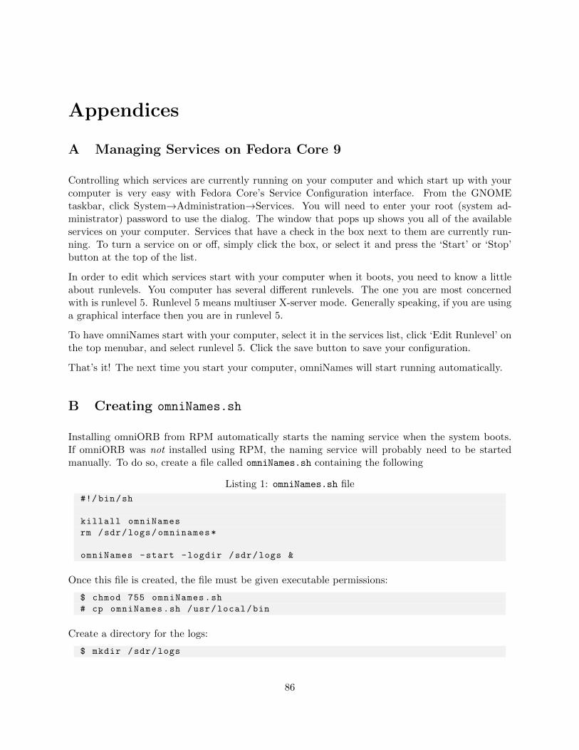
Appendices
A Managing Services on Fedora Core 9
Controlling which services are currently running on your computer and which start up with yourcomputer is very easy with Fedora Core’s Service Configuration interface. From the GNOMEtaskbar, click System→Administration→Services. You will need to enter your root (system ad-ministrator) password to use the dialog. The window that pops up shows you all of the availableservices on your computer. Services that have a check in the box next to them are currently run-ning. To turn a service on or off, simply click the box, or select it and press the ‘Start’ or ‘Stop’button at the top of the list.
In order to edit which services start with your computer when it boots, you need to know a littleabout runlevels. You computer has several different runlevels. The one you are most concernedwith is runlevel 5. Runlevel 5 means multiuser X-server mode. Generally speaking, if you are usinga graphical interface then you are in runlevel 5.
To have omniNames start with your computer, select it in the services list, click ‘Edit Runlevel’ onthe top menubar, and select runlevel 5. Click the save button to save your configuration.
That’s it! The next time you start your computer, omniNames will start running automatically.
B Creating omniNames.sh
Installing omniORB from RPM automatically starts the naming service when the system boots.If omniORB was not installed using RPM, the naming service will probably need to be startedmanually. To do so, create a file called omniNames.sh containing the following
Listing 1: omniNames.sh file
#!/ bin/sh
killall omniNames
rm /sdr/logs/omninames*
omniNames -start -logdir /sdr/logs &
Once this file is created, the file must be given executable permissions:
$ chmod 755 omniNames.sh
# cp omniNames.sh /usr/local/bin
Create a directory for the logs:
$ mkdir /sdr/logs
86
The script can now be run by executing omniNames.sh in any terminal. You can check to see ifomniNames is running by executing:
$ nameclt list
If the naming service is not running you will see an error like:
Unexpected error when trying to narrow the NamingContext.
87
C Configuring ossie.pth
In order for the Python tools to link properly, a Python path file must be created to point to theshared modules. The default ossie.pth file is located underossie-0.8.2/src/system/ossie/idl/python/ and is installed by default in/usr/lib/pythonX.X/site-packages when you install the ossie core framework libraries.
If you did not install omniORBpy using an RPM, you might need to add/usr/local/lib/pythonX.X/site-packages to ossie.pth, where X.X corresponds to the specificversion of Python installed on your system. Now reinstall by running python setup.py install
as root within theossie-0.8.2/system/ossie/idl/python/ directory:
# cd ossie -0.8.1/ system/ossie/idl/python/
# python setup.py install
88
D Data Source Component Creation
The component TxDemo will be used as an example on how to create a data source. Whencreating a component which is not a data source, typically only the function ProcessData needsto be modified to include the desired operation. This is not the case for a source component,however. The code that needs to be updated in this example resides in the start, stop, andProcessData functions. Locate the directory components/TxDemo and open the files TxDemo.hand TxDemo.cpp.
In TxDemo.h, near the end of the file the following code will be listed:
bool continue_processing(void);
volatile bool thread_started;
The flag thread started holds the state of the component; whether or not the component shouldcontinue sending data. A function continue processing is also declared which will be used tocheck thread started and determine if the component should continue sending packets.
In TxDemo.cpp, locate the start function and the following code will be listed:
omni_mutex_lock l(processing_mutex );
if (false == thread_started ){
thread_started = true; // initialize
// Create the thread for the writer ’s processing function
processing_thread = new omni_thread(Run , (void *) this);
//Start the thread containing the writer ’s processing function
processing_thread ->start ();
}
This code creates a new thread and starts processing when the thread started variable is set totrue.
Now locate the stop function, and the following code will be listed:
omni_mutex_lock l(processing_mutex );
thread_started=false;
This code stops the processing on the thread by setting thread started to false.
Now locate the ProcessData function, and the following code will be listed:
while(continue_processing ()) {
// push data to output
dataOutPort ->pushPacket(I_out , Q_out);
// wait
usleep(packet_delay *1000);
}
89
This code checks the function continue processing to determine if packets should continue tobe sent using pushPacket. The usleep function call is specific to TxDemo, and is not necessarilyrequired in other data sources.
The last section of code that must be created is the continue processing function. The code forthe function is listed as the following:
bool TxDemo_i :: continue_processing(void)
{
omni_mutex_lock l(processing_mutex );
return thread_started;
}
All of the code listings provided above are not created by default when a new component is gener-ated, since the code is only required for source components. Instead, all of the code must be addedby hand. The addition of the code will create the appropriate environment for the data source, andafterwards only the data creation must be added to the ProcessData function.
90
E Known Bugs
E.1 OSSIE Core Framework
1. After running a waveform, nodeBooter must be killed using Ctrl-C and does not exit grace-fully.
2. Running wavLoader.py results in two copies of each SAD file, for example:
1: //waveforms/ossie_demo/ossie_demo.sad.xml
2: /DeviceManager/waveforms/ossie_demo/ossie_demo.sad.xml
This is an artifact of the filesystem. You should always choose the first one and ignore thesecond.
E.2 OWD
1. Generating components with certain interfaces result in code that cannot be compiled directly.OWD generates the source, but will display a warning in the terminal:
Interfaces other than complex and real Short, Float, Char, long and Double
are not supported yet in the process data function generation!!
See writeProcessDataDeclaration in genStructure.
2. When trying to assign a component to a device in the “Waveform Deployment Settings”section in the OSSIE Component Editor window, if the “Node” is not properly selected, nodevices will appear in the spinbox.
3. When generating a waveform, the configure.ac file includes tests for source code instead ofjust installation.
4. After opening ComponentFrame from OWD for a new component, Python will not quit whenyou quit OWD.
E.3 ALF
1. Waveforms with more than about fifteen components will not display properly and are cutoff from view.
E.4 WaveDash
1. Display of dialog does not expand to support large words.
91

E.5 c wavLoader
1. c wavLoader can only be used to install one waveform per run of nodeBooter. To usec wavLoader to install another waveform, nodeBooter must first be restarted.
92
F List of Abbreviations
ALF (not an acronym) A waveform application visualization and debugging environment forOSSIE
DAS Device Assignment Sequence
JTRS Joint Tactical Radio System
OSSIE Open-source SCA Implementation::Embedded
OWD OSSIE Waveform Developer
QPSK Quadrature phase-shift keying
SAD Software Assembly Descriptor
SCA Software Communications Architecture
93
References
[1] Autoconf. http://www.gnu.org/software/autoconf/.
[2] Automake. http://www.gnu.org/software/automake/.
[3] Doxygen. http://www.stack.nl/~dimitri/doxygen/.
[4] GNU General Public License. http://www.gnu.org/licenses/old-licenses/gpl-2.0.
html#TOC1.
[5] GNU Lesser General Public License. http://www.gnu.org/licenses/old-licenses/
lgpl-2.1.html#TOC1.
[6] IRC Tutorial. http://www.irchelp.org/irchelp/irctutorial.html.
[7] Linux kernel coding style. http://pantransit.reptiles.org/prog/CodingStyle.html.
[8] The JTRS Software Communications Architecture. http://sca.jpeojtrs.mil/.
[9] VMWare Player User Manual. http://www.vmware.com/pdf/vmware_player200.pdf.
[10] E. Buracchini. The Software Radio Concept. IEEE Commun. Mag., 38(9):138–143, 2000.
[11] J. H. Reed. Software Radio: a Modern Approach to Radio Engineering. Prentice Hall, UpperSaddle River, 2002.
[12] John Bard and Vincent J Kovarik. Software Defined Radio: The Software CommunicationsArchitecture. Wiley, Hoboken, NJ, 2007.
[13] Simon Tatham. How to Report Bugs Effectively. http://www.chiark.greenend.org.uk/
~sgtatham/bugs.html.
94
G Change Log
G.1 OSSIE 0.8.2
All changes in 0.8.2 involve the tools
1. ALF tries to find a domain manager using a local naming service when ALF is first started.If a domain manager is not found using the local naming service, ALF pops up a dialogbox. The user can then specify an IP address for a remote naming service or start a domainmanager locally using icons in the ALF toolbar.
2. The nodeBooter can now be started from either ALF or WaveDash by clicking on the rightmost icon in the tool bar (monitor with triangle/arrow). This allows the user to choosea domain manager and a device manager. The domain manager is optional and can bedeselected.
3. OEF 1.1.7 supports multiple instances of a component in a waveform, on the same nodeor on different nodes. In previous versions multiple instances were all assigned the sameinstantiation ID.
4. OSSIE preferences file allows users the option to replace the default GPP license text witha license of their choice. From Eclipse menu bar: Window -> Preferences -> OSSIE ->
License, then paste in new license text.
5. OEF now supports creating python components that use long, bool, and string properties.
6. WaveDash now includes two new views: a command line interface and an HTTP server
7. WaveDash backend now can run without X11. (wasn’t included in 0.8.1 tarball, need to fixmakefile)
G.2 OSSIE 0.8.1
1. Components and Devices now accept standard command line parameters.
2. ALF and WaveDash now use the CF::FileSystem to query for available components andapplications.
3. Distribution of components across multiple nodes is significantly simpler.
4. Core Framework now supports boolean, char, and octal component property types.
5. OEF 1.1.5 now supports node generation.
6. WaveDash now supports updating property values immediately or on a per-component orper-waveform basis.
95
G.3 OSSIE 0.8.0
1. CF::FileSystem now encapsulates the Boost file system library
2. Xerces has been replaced by TinyXML
3. The install directory structure has changed to separate Domain management from Devicemanagement
4. The nodeBooter and c wavLoader utilities support ’-debug’ level flag and any compatibleORB flags (i.e. -ORBInitRef)
G.4 OSSIE 0.7.4
1. Addition of new waveform: Lab 5 example AM application.
2. AutomaticGainControl component will output ones when threshold is not met.
3. ALF ConnectTool has improved support for port connections.
4. WaveDash can now control single-component waveforms created and launched in ALF.
5. ALF allows user to specify IP address for CORBA naming service.
G.5 OSSIE 0.7.3
1. Introduction of Waveform Dashboard (WaveDash).
2. Addition of new waveforms: OSSIETalkLoopBack, OSSIETalkUSRP.
3. Addition of new components: Channel, Conv Dec, Conv Enc, DigitalModem, FrameAssem-bler, OSSIETalk, PacketResizer, SymbolSyncPoly.
4. Decimator has the ability to use either IIR or FIR.
5. OWD provides generation of custom license headers.
6. More removal of vestigial project files.
G.6 OSSIE 0.7.2
1. Improved start/stop capability within TxDemo component.
2. Corrected XML Template files for OWDC component generation.
3. Removal of incorrect entry point tags in default GPP node SPD.
4. Deletion of vestigial project files.
5. Addition of Interpolator component.
96
G.7 OSSIE 0.7.1
1. Removal of duplicate profile templates.
2. Added start, stop capability to TxDemo component.
3. Fixed USRP Commander rx freq property typo.
4. Fixed capability of components being run as waveforms.
G.8 OSSIE 0.7.0
1. Start of change log.
2. Allows for non /sdr install.
3. Installation through RPMs.
4. ALF can start and stop waveforms.
5. Reduced plot tool’s refresh rate.
6. Removed “sample waveform” option in OWD.
7. Removed duplicate DOCTYPE descriptors in generated XML files.
8. Fixed path in USRP’s SCD file.
9. Fixed soundCardCapture device name to prevent OWD error.
10. Added Ubuntu 8.04 as supported platform.
11. OWD default save directory is now home directory.
12. ALF’s plot tool has normalized frequency axis.
13. Debug statements use DEBUG macro instead of std::cout.
14. Tools now installed to site-packages.
15. ALF, OWD, and OWD Component Editor can be run from any directory.
16. More than two nodes can be run through a single domain manager.
17. Added webcam components.
18. Installation from source broken into two steps.
97