orv-ms45 - transnordic€¦ · 3 orv-ms45 working conditions. not: this catalogue shows technical...
TRANSCRIPT


2
ORV-MS45
Contents
Working Conditions _________________________________________________________ 3
Dimensional Data ___________________________________________________________ 4
Hydraulic Circuit ___________________________________________________________ 5
Performance Data And Curve _________________________________________________ 6
Inlet Relief Options _________________________________________________________ 7
Ordering Codes _____________________________________________________________ 8
Spool Options _____________________________________________________________ 10
Spool Positioners – Side of Return ____________________________________________ 13
Spool Positioners – Side of Lever Control _______________________________________ 15
Spool Positioners – Side of Lever Control _______________________________________ 16
Spool Positioners – Side of Lever Control _______________________________________ 17
Outlet Port Options _________________________________________________________ 18
Outlet Port Options _________________________________________________________ 19
Installation and Maintenance ________________________________________________ 20
Technical Data ____________________________________________________________ 21
Additional Informations
Note:This catalog shows the product in the most standard configurations. For Other Configurations, more detailed information or special request, Please contact Customer Service Dpt. Warning! :All specifications of this catalog refer to the standard product at this date (07/2014) . ORVAL, oriented to a continuous improvement, reserves the right to discontinue, modify or revise the specifications, without notice. ORVAL IS NOT RESPONSIBLE FOR ANY DAMAGE CAUSED BY AN INCORRECT USE OF THE PRODUCT.

3
ORV-MS45
Working Conditions
Not: This catalogue shows technical specifications measured with mineral oil of 46 mm2/s-46 cSt viscosity at 40 C˚ temparture.
Features
Simple, compact and heavy duty designed monoblock valves from 1 to 7 sections for open and closed center hydraulic systems.
Fitted with a main pressure relief valve and a load check valve.
Optionaly Carry-Over port only parallel circuit.
Interchangeable spool diameter is 16 mm – 0,63 in.
Available manual, pneumatic, hydraulic and electro-pneumatic spool control kits.
Nominal Flow Rating / Displacement 45 l/min 12 U.S.G.P.M
Maximum Working Pressure (Parallel Circuit) 315 Bar 4600 PSI
(Series Circuit) 250 Bar 3600 PSI
Max. Back Pressure 25 Bar 360 PSI
Oil Temperature with NBR Seals -20 to 80 C˚ -4 to 176 F ˚
with FPM (Viton) Seals -20 to 100 C˚ -4 to 212 F ˚
Oil Viskosity – Operating Range From 10 to 75 mm2/s From 10 to 75 cSt
Minumum / Maximum 10 / 400 mm2/s 10 / 400 cSt
Oil Filtration ≤30 µ
Ambiant Temperature Range -35 to 60 C˚ -31 to 140 F ˚
Number Of Spools 1 to 7
Internal Leakage (at 100 bar (1450 PSI), 40C˚ (110 F˚), 46 cSt – A(B)—T)
3 cm3/min 0,18 in3/min
Max. Level Of Contamination 19/16 - ISO 4406

4
ORV-MS45
Dimensional Data
TYPE A mm in
B mm in
Weight Kg lb
ORV-MS45-1P 97 4,25 116 4,56 4,00 8,18
ORV-MS45-2P 133 5,23 152 5,98 6,00 13,23
ORV-MS45-3P 169 6,65 188 7,40 7,40 16,31
ORV-MS45-4P 205 8,07 224 8,82 9,00 19,84
ORV-MS45-5P 241 9,49 260 10,23 10,60 23,37
ORV-MS45-6P 277 10,90 296 11,65 12,30 27,12
ORV-MS45-7P 313 12,32 332 13,07 14,00 30,86
Standard Threads
PORT BSP (Iso 228) 3/8” Series ½”Series
UN-UNF (Iso 11926-1) Metric (Iso 262)
P lnlet G 3/8 G 1/2 3/4-16 UNF M18x1.5
A-B Ports G 3/8 G 1/2 9/16-18 UNF M18x1.5
T Outlet G 1/2 G 1/2 3/4-16 UNF M18x1.5
Pneumatic G 1/4 G 1/4 NPTF 1/8 - 27 NPTF 1/8 - 27
Carry-Over G 1/2 G 1/2 3/4-16 UNF G 1/2

5
ORV-MS45
Hydraulic Circuit
Parallel - Standard Configurations With Side Inlet And Outlet Open Center
Code:ORV MS45-2P / SMR2-120 / 1A-SR-STL/1A-SR-STL/PA1/SGT

6
ORV-MS45
Performance Data And Curve
Note: Measured and chart value with spool type 1A.
Open Center - Pressure Drop (P-T)
Inlet to Work Port - Pressure Drop (P-A/B)
Work Port to Outlet - Pressure Drop (A/B-T)

7
ORV-MS45
Code:
SMR2 – 120 Pressure Setting Bar in (Standard 120 bar)
Standard Main Relief Spring Type -2
Performance Data:
Adjustment Type on Valve:
Inlet Relief Options
Direct Pressure Relief Valve
Relief Blanking Plug - WM
Spring Type Number : 1 Setting= 80 Bar -Range=63-125 Bar
Spring Type Number : 3 Setting= 220 Bar -Range=200-315 Bar
Spring Type Number : 2 Setting= 120 Bar -Range=100-165 Bar
8
ORV-MS45
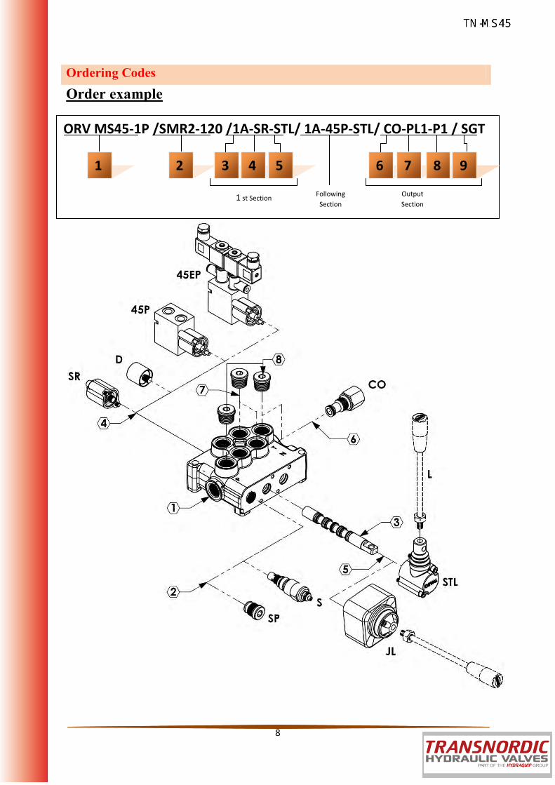
Ordering Codes
Order example
ORV MS45-1P /SMR2-120 /1A-SR-STL/ 1A-45P-STL/ CO-PL1-P1 / SGT
1 2 3 6 7 4 5 8
1 st Section Following
Section
Output
Section
9 9

9
ORV-MS45
Ordering Codes
1-Valve Type and Body
5-Lever Options
6- Output Options
2-Pressure Relief Options
7-Ports Plug Options "If Required"
3-Spool Options
8- Ports Input Plug Options
9- Ports Thread Options
HandLever
4- Spool Positioners
M45 =Valve Type - (MS) - Monoblok (45) - Max. Flow Rate
1P =Body for 1 Section - (1BMS145100)
2P =Body for 2 Sections - (1BMS245100)
3P =Body for 3 Sections - (1BMS345100)
4P =Body for 4 Sections - (1BMS445100)
5P =Body for 5 Sections - (1BMS545100)
6P =Body for 6 Sections - (1BMS645100)
SMR = Standard direct pressure relief valve SMR1-080 – (2SMR145080)–Range 0-80 bar
Setting 80 bar
SMR2-120 – (2SMR245120)–Range 60-200 bar
Setting 120 bar
SMR3-220 – (2SMR345220)–Range 160-315 bar
Setting 220 bar
SP =Standard relief plug – (2SP045100)
1A -(3SMS145110) – 3 Positions ,Double acting 2A -(3SMS145120) – 3 Positions ,Double acting A to tank B Blocked 3A -(3SMS145130) – 3 Positions ,Double acting B to tank A blocked 4A -(3SMS145140) – 3 Positions ,Double acting A and B tank 5A -(3SMS145150) – 3 Positions ,Single acting on A (A to tank) 6A -(3SMS145160) – 3 Positions ,Single acting on B (B to tank)
SR=Spring Return in neutral position – (4SR045100)
D =Detent in position 1, neutral and 2 -
(4D045100)
45P=ON/OFF Pneumatic – (445P045100)
45EP=12 VDC ON/OFF electro-pneumatic –
(445EP045112)
24 VDC ON/OFF electro-pneumatic –
(445EP045124)
STL=Standard Lever –(5STL045100)
JL=Joystick lever for two sections operation - (5JL 080100)
PL1(5A) =Plug for single action spool for 5A G1/2 –(6PL1040112)
PL1(6A) =Plug for single action spool for 6A G1/2 –(6PL1040112)
PL2(5A) =Plug for single action spool for 5A G3/8- (7PL2045138)
PL2(6A) =Plug for single action spool for 6A G3/8- (7PL2045138)
*Page 13 for detail spool options.
L =Standard HandLever (L=120mmxM10) - (7L040100)
PI1(T) = G1/2 Top input – (6PL1040112) PI1(S) = G1/2 Side input – (6PL1040112) PI2(T) = G3/8 Top input – (7PL2045138) PI2(S) = G3/8 Side input – (7PL2045138)
PA1(T) =G1/2” Top output plug- (6PL1040112) PA1(S) =G1/2” Side output plug- (6PL1040112) CO =G1/2” Carry–Over Connector –
(6CO045100)
SGT1 =1/2" Series Port Options - (9P045112) SGT2 =3/8" Series Port Options - (9P045138) UNF =UNF Series Port Options - (9U045138) M =Metric Series Port Options - (9M045138) *Page 4 for detail port information.
10
ORV-MS45
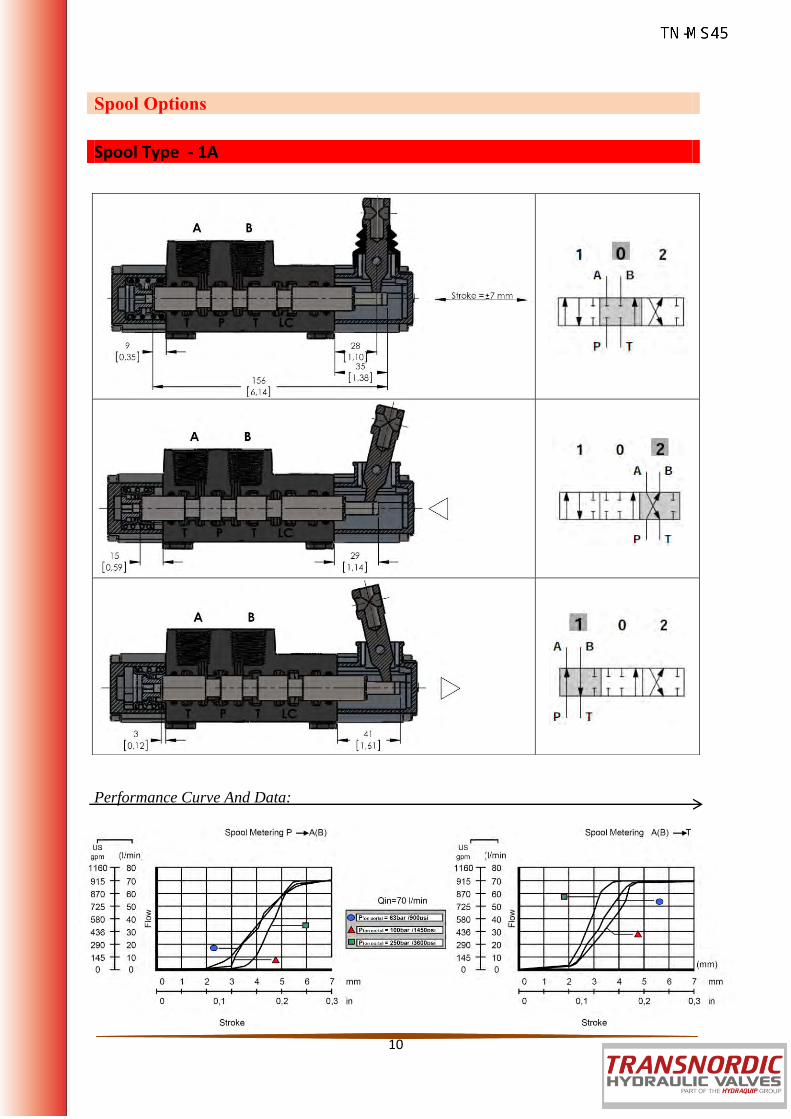
Spool Options
Performance Curve And Data:
Spool Type - 1A

11
ORV-MS45
Spool Options
Spool Type - 2A
Spool Type - 3A
Spool Type - 4A

12
ORV-MS45
Spool Options
Spool Type - 5A
Spool Type - 6A

13
ORV-MS45
Kit No: SR
Sectional Apperance Diagram
Kit No: D
Sectional Apperance Diagram
Spool Positioners – Side of Return
With Spring Return in Neutral Position
With Detent

14
ORV-MS45
Kit No: 80P
Sectional Appearance Diagram
Operatig Features Pilot Pressure ……………………..: 6 Bar (Max. 10) / 87 Psi (Max. 145)
Kit No: 80EP
Sectional Appearance Diagram
Operatig Features Pilot Pressure ……………………..: 6 Bar (Max. 10) / 87 Psi (Max. 145) Selonoid Operating Features Nominal Voltage…………..……..: 12VDC / 24 VDC Power Rating……………………….: 6 W
Spool Positioners – Side of Return
ON/OFF Pneumatic Control
ON/OFF Electro-Pneumatic Control

15
ORV-MS45
Spool Positioners – Side of Lever Control
Lever Controls
Kit No: STL - L0
Sectional Appearance Diagram
Kit No: STL - L180
Sectional Appearance Diagram
Note: Aluminium with protection arm lever pivot box, it can be rotated 180⁰.

16
ORV-MS45
Operation Angle:
Spool Positioners – Side of Lever Control
Lever Controls - Joystick
Kit No: JL
Explode Appearance Diagram
17
ORV-MS45
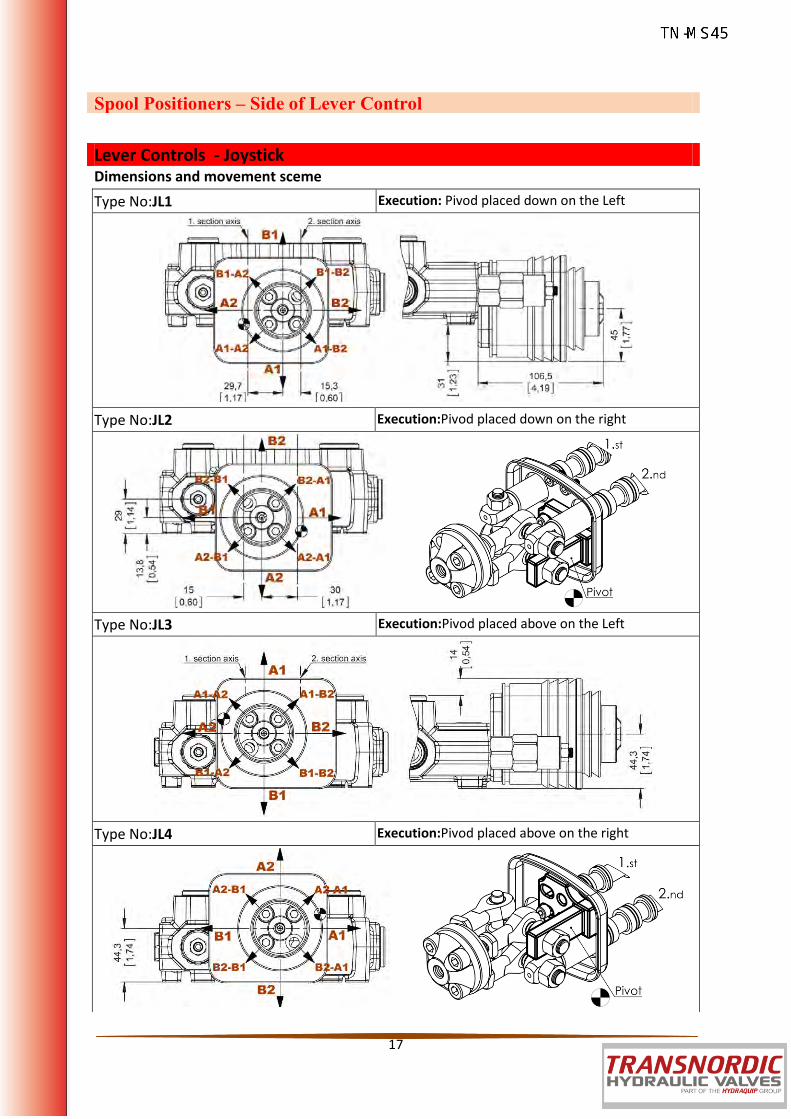
Dimensions and movement sceme
Spool Positioners – Side of Lever Control
Lever Controls - Joystick Type No:JL1 Execution: Pivod placed down on the Left
Type No:JL2 Execution:Pivod placed down on the right
Type No:JL3 Execution:Pivod placed above on the Left
Type No:JL4 Execution:Pivod placed above on the right
18
ORV-MS45
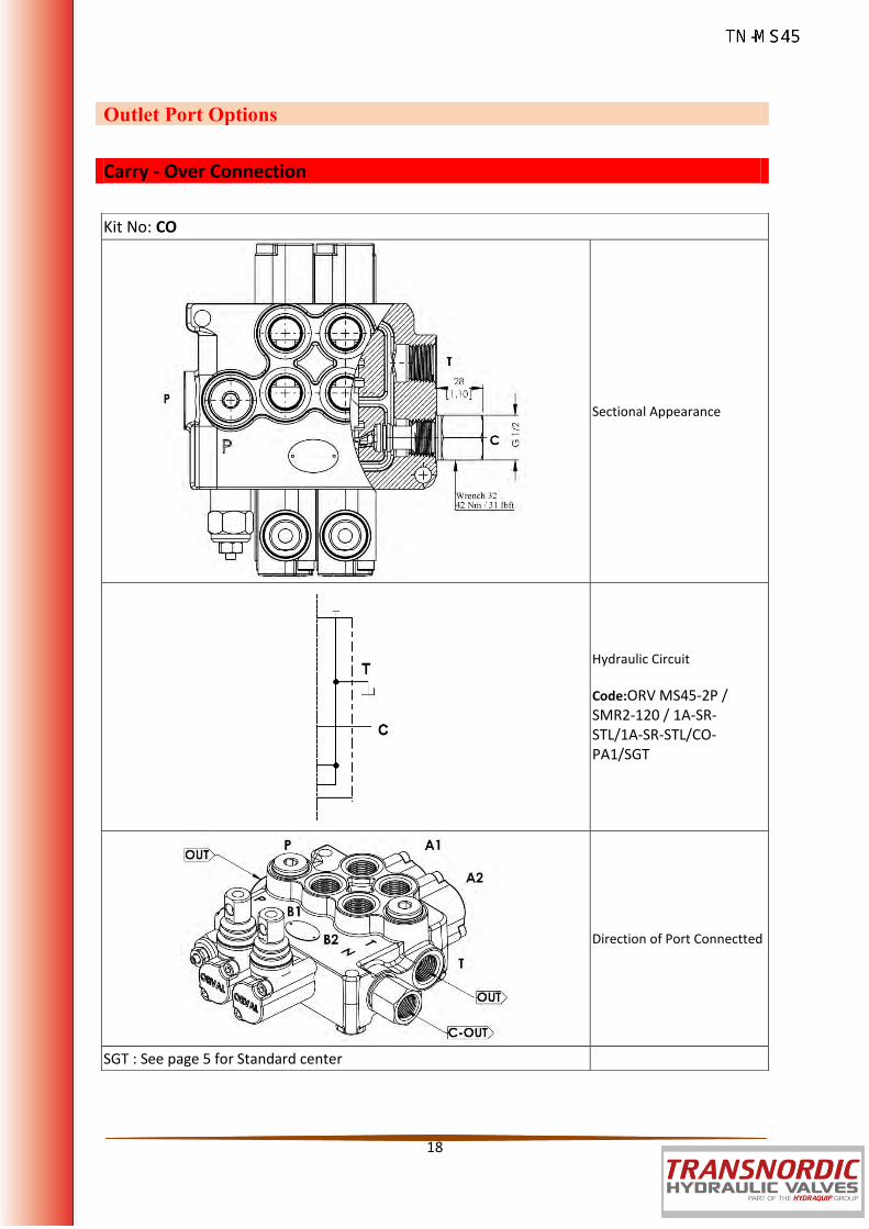
Outlet Port Options
Carry - Over Connection
Kit No: CO
Sectional Appearance
Hydraulic Circuit
Code:ORV MS45-2P / SMR2-120 / 1A-SR-STL/1A-SR-STL/CO-PA1/SGT
Direction of Port Connectted
SGT : See page 5 for Standard center

19
ORV-MS45
Outlet Port Options
Closed Center
Kit No: CS
Sectional Appearance
Hydraulic Circuit
Code:ORV MS45-2P / SMR2-120 / 1A-SR-STL/1A-SR-STL/CT-PA1/SGT

20
ORV-MS45
B2
Installation and Maintenance The ORV MS45 valve is assembled and tested as per the technical specification of this catalog. Before the final installation on your equipment, follow the below recommendation:
The valve can be assembled in any position, in order to prevent body deformation and spool sticking mount the product on a flat surface;
In order to prevent the possibility of water entering the lever box and spool control kit, do not use high pressure wash down directly on the valve;
Prior to painting, ensure plastic port plugs are tightly in place.
Threads Type (Nm / Ibft) P Port A and B Port T and CPort BSP (ISO 228/1) G 3/8 G 3/8 G 1/2 With O--Ring seal 35 / 25.8 35 / 25.8 50 / 36.9 With copper washer 40 / 29.5 40 / 29.5 60 / 44.3 With steel and rubber washer 30 / 22.1 30 / 22.1 60 / 44.3
BSP (ISO 228/1) G 1/2 G 1/2 G 1/2 With O--Ring seal 50 / 36.9 50 / 36.9 50 / 36.9 With copper washer 60 / 44.3 60 / 44.3 60 / 44.3 With steel and rubber washer 60 / 44.3 60 / 44.3 60 / 44.3
UN--UNF (ISO 11926--1) 3/4--16 UNF--2B 9/16--18 UNF--2B 3/4--16 UNF--2B With O--Ring seal 50 / 36.9 30 / 22.1 50 / 36.9
METRIC (ISO 262) M18 x 1.5 M18 x 1.5 M18 x 1.5 With O--Ring seal 35 / 25.8 35 / 25.8 35 / 25.8 With copper washer 40 / 29.5 40 / 29.5 40 / 29.5 With steel and rubber washer 40 / 29.5 40 / 29.5 40 / 29.5
C Port
T Port
P Port
B1 A1
A2

21
ORV-MS45
Technical Data
Ports Dimensional Data
SAE UN-UNF (ISO 725) Dimensions 9/16-18 UNF
SAE6 3/4-16 UNF
SAE8 7/8-14 UNF
SAE10 mm in
A 13 0,51 15 13 0,51 15
B 25 0,83 30 25 0,83 30
C 13,6 0,61 20,6 13,6 0,61 20,6
D 2,5 0,10 2,5 2,5 0,10 2,5
E 15˚ 15˚ 15˚
BSP (ISO 228) Dimensions
G1/4 G3/8 G1/2 mm
A 14 0,55 14 14 0,55 14
B 19 0,75 23 19 0,75 23
METRIC (ISO 262) Dimensions M18x1,5
ISO 262 M22x1,5 ISO 262 mm in
A 14 0,55 14 0,55
B 27,5 1,08 27,5 1,08
