orthopaedics gmrs distal femoral surgical protocol · curved; each type with or without...
TRANSCRIPT
Orthopaedics
GMRS™ Distal FemoralSurgical Protocol
Global Modular Replacement System

AcknowledgementsStryker® would like to thank the follow-ing surgeons for their contributions indeveloping the Global ModularReplacement System (GMRS™).
Jeffery Eckardt, M.D.
Rainer Kotz, M.D.
Martin Malawer, M.D.
Mario Mercuri, M.D.
Stryker® would also like to thank the following surgeons for their input inreviewing this surgical technique.
Francis Hornicek, M.D.
Lawrence Menendez, M.D.
Richard Lackman, M.D.
Franklin Sim, M.D.
H. Thomas Temple, M.D.
GMRS™ Distal Femoral components are marketed in the United States for use with bone cement.
Orthopaedics
GMRS™ Distal FemoralSurgical Protocol
Table of Contents
Introduction 2
Description of the Distal FemoralGlobal Modular Replacement System 4
Surgical Protocol 7
Measuring Resection Length 8Rotational Alignment 9Femoral Osteotomy 10Preparation of the Femur 11Proximal Tibial Resection 12Tibial Preparation for the Modular Rotating Hinge (MRH) Tibial Baseplate 13Establishing the depth of the tibial cut 14Proximal Tibial Resection 15Femoral and Tibial Trial Assembly 17Trial Reduction 18Assembly of the Tibial Stem Implant 20Titanium Tri-Fluted Stem Option 20Assembly of the Femoral Prosthesis 21Implantation and Orientation of the Tibial and Femoral Prosthesis 23Final Implant Assembly 24
Appendices
Appendix I – Establishing the Depth of the Tibial Cut
Option A: Femoral Referencing Method 28Option B: Extra-Medullary Referencing 30Option C: Intra-Medullary Referencing 34
Appendix II – Tibial Preparation for theAll-Poly Tibial Component 40
Appendix III – Taper Disassembly 46
Implant Listing and Resection Length Overview Chart 48, 49
1
2
GMRS™
Distal Femoral Surgical Protocol
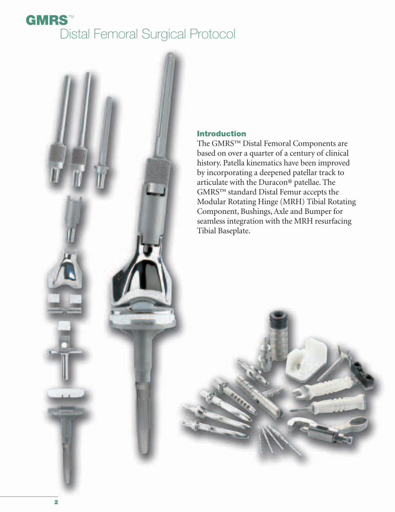
IntroductionThe GMRS™ Distal Femoral Components arebased on over a quarter of a century of clinicalhistory. Patella kinematics have been improved by incorporating a deepened patellar track toarticulate with the Duracon® patellae. TheGMRS™ standard Distal Femur accepts theModular Rotating Hinge (MRH) Tibial RotatingComponent, Bushings, Axle and Bumper forseamless integration with the MRH resurfacingTibial Baseplate.
3
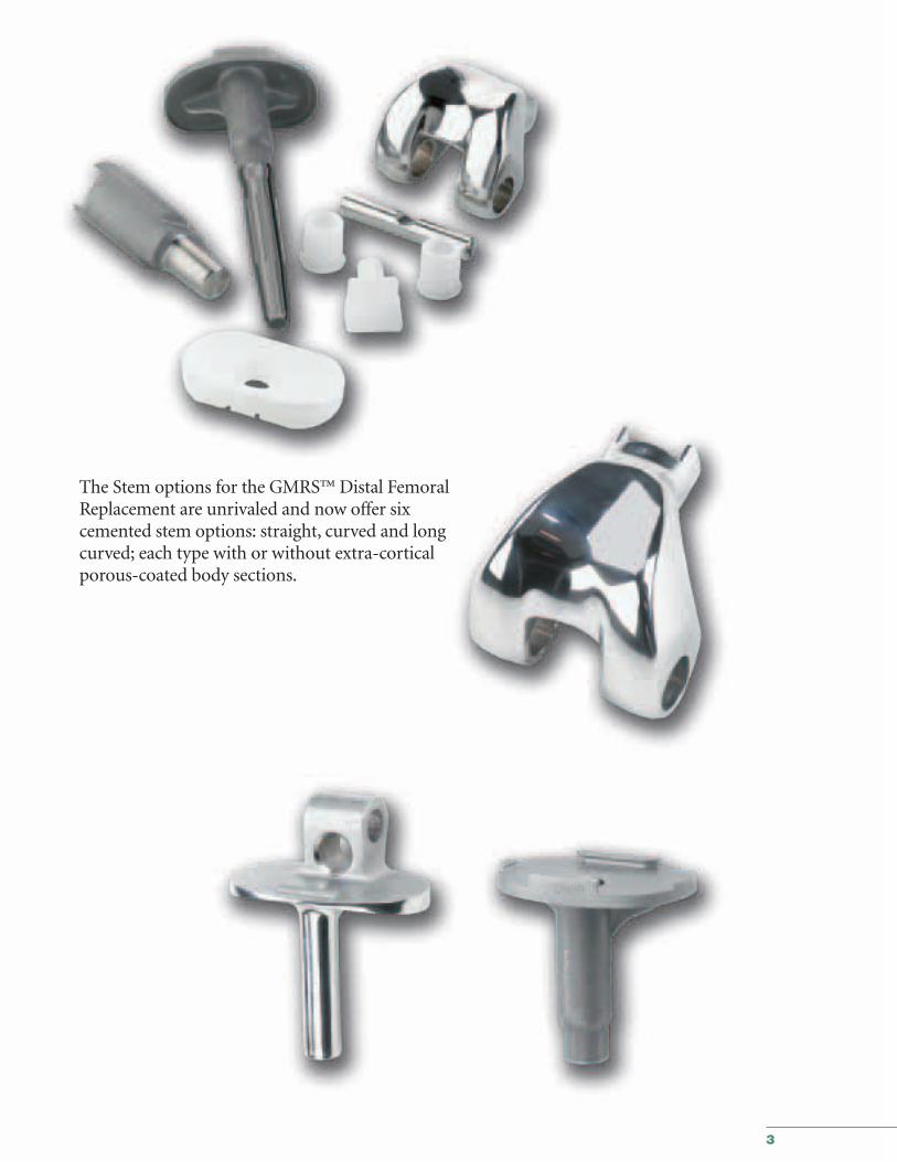
The Stem options for the GMRS™ Distal FemoralReplacement are unrivaled and now offer sixcemented stem options: straight, curved and longcurved; each type with or without extra-corticalporous-coated body sections.
4
GMRS™
Distal Femoral Surgical Protocol
Stem ComponentsCemented StemsThe GMRS™ cemented stems are available in six styles:straight, curved and long curved; each style with or withoutextra-cortical porous-coated body sections. The extra-corticalporous-coated body section has a 40mm replacement length.The stems are also available without the extra-cortical porous-coated body section, with an 11mm replacement length.
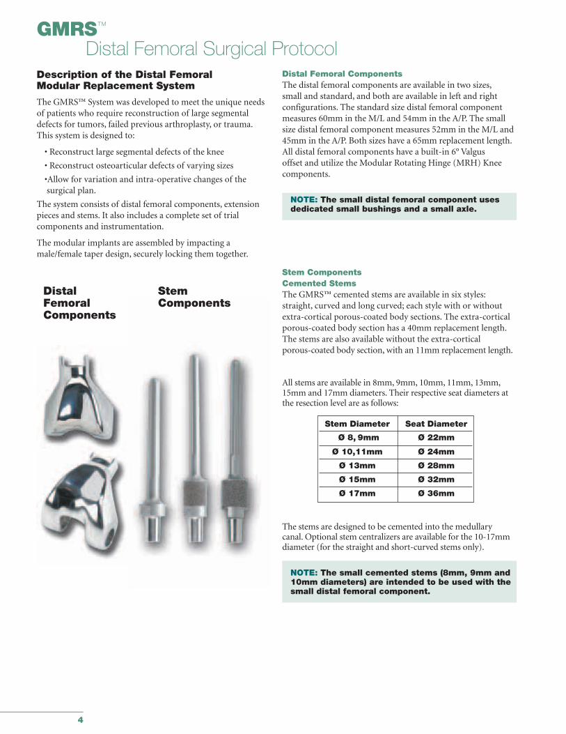
Description of the Distal Femoral Modular Replacement System
The GMRS™ System was developed to meet the unique needs of patients who require reconstruction of large segmentaldefects for tumors, failed previous arthroplasty, or trauma.This system is designed to:
• Reconstruct large segmental defects of the knee
• Reconstruct osteoarticular defects of varying sizes
•Allow for variation and intra-operative changes of the surgical plan.
The system consists of distal femoral components, extensionpieces and stems. It also includes a complete set of trial components and instrumentation.
The modular implants are assembled by impacting amale/female taper design, securely locking them together.
Distal Femoral ComponentsThe distal femoral components are available in two sizes,small and standard, and both are available in left and right configurations. The standard size distal femoral componentmeasures 60mm in the M/L and 54mm in the A/P. The small size distal femoral component measures 52mm in the M/L and45mm in the A/P. Both sizes have a 65mm replacement length.All distal femoral components have a built-in 6° Valgus offset and utilize the Modular Rotating Hinge (MRH) Kneecomponents.
NOTE: The small distal femoral component uses dedicated small bushings and a small axle.
DistalFemoralComponents
StemComponents
All stems are available in 8mm, 9mm, 10mm, 11mm, 13mm,15mm and 17mm diameters. Their respective seat diameters atthe resection level are as follows:
The stems are designed to be cemented into the medullary canal. Optional stem centralizers are available for the 10-17mmdiameter (for the straight and short-curved stems only).
NOTE: The small cemented stems (8mm, 9mm and 10mm diameters) are intended to be used with the small distal femoral component.
Stem Diameter Seat Diameter
Ø 8, 9mm Ø 22mm
Ø 10,11mm Ø 24mm
Ø 13mm Ø 28mm
Ø 15mm Ø 32mm
Ø 17mm Ø 36mm
5
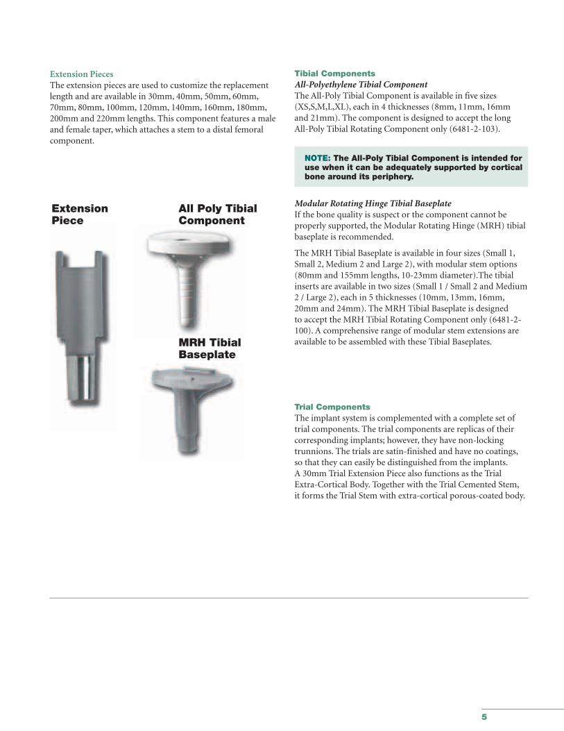
Tibial ComponentsAll-Polyethylene Tibial ComponentThe All-Poly Tibial Component is available in five sizes(XS,S,M,L,XL), each in 4 thicknesses (8mm, 11mm, 16mm and 21mm). The component is designed to accept the long All-Poly Tibial Rotating Component only (6481-2-103).
NOTE: The All-Poly Tibial Component is intended for use when it can be adequately supported by cortical bone around its periphery.
Modular Rotating Hinge Tibial BaseplateIf the bone quality is suspect or the component cannot be properly supported, the Modular Rotating Hinge (MRH) tibialbaseplate is recommended.
The MRH Tibial Baseplate is available in four sizes (Small 1,Small 2, Medium 2 and Large 2), with modular stem options(80mm and 155mm lengths, 10-23mm diameter).The tibialinserts are available in two sizes (Small 1 / Small 2 and Medium 2 / Large 2), each in 5 thicknesses (10mm, 13mm, 16mm,20mm and 24mm). The MRH Tibial Baseplate is designed to accept the MRH Tibial Rotating Component only (6481-2-100). A comprehensive range of modular stem extensions areavailable to be assembled with these Tibial Baseplates.
Trial ComponentsThe implant system is complemented with a complete set oftrial components. The trial components are replicas of their corresponding implants; however, they have non-locking trunnions. The trials are satin-finished and have no coatings,so that they can easily be distinguished from the implants.A 30mm Trial Extension Piece also functions as the Trial Extra-Cortical Body. Together with the Trial Cemented Stem,it forms the Trial Stem with extra-cortical porous-coated body.
ExtensionPiece
MRH TibialBaseplate
All Poly TibialComponent
Extension PiecesThe extension pieces are used to customize the replacementlength and are available in 30mm, 40mm, 50mm, 60mm,70mm, 80mm, 100mm, 120mm, 140mm, 160mm, 180mm,200mm and 220mm lengths. This component features a maleand female taper, which attaches a stem to a distal femoralcomponent.

6
7
Orthopaedics
GMRS™ Distal FemoralSurgical Protocol
This publication sets forth detailed recommended procedures for using Stryker® Orthopaedics devices and instruments. It offers guidance that you should heed, but,as with any such technical guide, each surgeon must consider the particular needs of each patient and make appropriate adjustments when and as required.
Global Modular Replacement System Distal Femoral Resection for Large Segmental Replacements Surgical Protocol
8
GMRS™
Distal Femoral Surgical Protocol
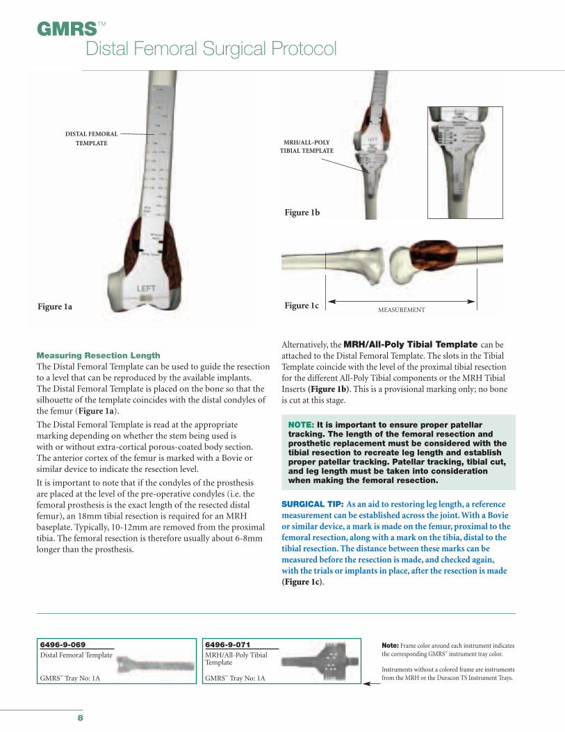
Alternatively, the MRH/All-Poly Tibial Template can beattached to the Distal Femoral Template. The slots in the TibialTemplate coincide with the level of the proximal tibial resectionfor the different All-Poly Tibial components or the MRH TibialInserts (Figure 1b). This is a provisional marking only; no boneis cut at this stage.
NOTE: It is important to ensure proper patellar tracking. The length of the femoral resection and prosthetic replacement must be considered with the tibial resection to recreate leg length and establish proper patellar tracking. Patellar tracking, tibial cut, and leg length must be taken into consideration when making the femoral resection.
SURGICAL TIP: As an aid to restoring leg length, a reference measurement can be established across the joint. With a Bovieor similar device, a mark is made on the femur, proximal to thefemoral resection, along with a mark on the tibia, distal to thetibial resection. The distance between these marks can be measured before the resection is made, and checked again,with the trials or implants in place, after the resection is made(Figure 1c).
Measuring Resection LengthThe Distal Femoral Template can be used to guide the resectionto a level that can be reproduced by the available implants.The Distal Femoral Template is placed on the bone so that thesilhouette of the template coincides with the distal condyles ofthe femur (Figure 1a).
The Distal Femoral Template is read at the appropriate marking depending on whether the stem being used is with or without extra-cortical porous-coated body section.The anterior cortex of the femur is marked with a Bovie orsimilar device to indicate the resection level.
It is important to note that if the condyles of the prosthesis are placed at the level of the pre-operative condyles (i.e. thefemoral prosthesis is the exact length of the resected distalfemur), an 18mm tibial resection is required for an MRH baseplate. Typically, 10-12mm are removed from the proximaltibia. The femoral resection is therefore usually about 6-8mmlonger than the prosthesis.
Figure 1a
DISTAL FEMORAL
TEMPLATE
Figure 1c
Figure 1b
MEASUREMENT
MRH/ALL-POLYTIBIAL TEMPLATE
6496-9-069Distal Femoral Template
GMRS™ Tray No: 1A
Note: Frame color around each instrument indicatesthe corresponding GMRS™ instrument tray color.
Instruments without a colored frame are instrumentsfrom the MRH or the Duracon TS Instrument Trays.
6496-9-071MRH/All-Poly TibialTemplate
GMRS™ Tray No: 1A
9
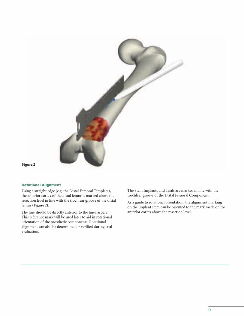
Rotational Alignment
Using a straight edge (e.g. the Distal Femoral Template),the anterior cortex of the distal femur is marked above theresection level in line with the trochlear groove of the distalfemur (Figure 2).
The line should be directly anterior to the linea aspera.This reference mark will be used later to aid in rotational orientation of the prosthetic components. Rotational alignment can also be determined or verified during trial evaluation.
The Stem Implants and Trials are marked in line with thetrochlear groove of the Distal Femoral Component.
As a guide to rotational orientation, the alignment marking on the implant stem can be oriented to the mark made on theanterior cortex above the resection level.
Figure 2
10
GMRS™
Distal Femoral Surgical Protocol
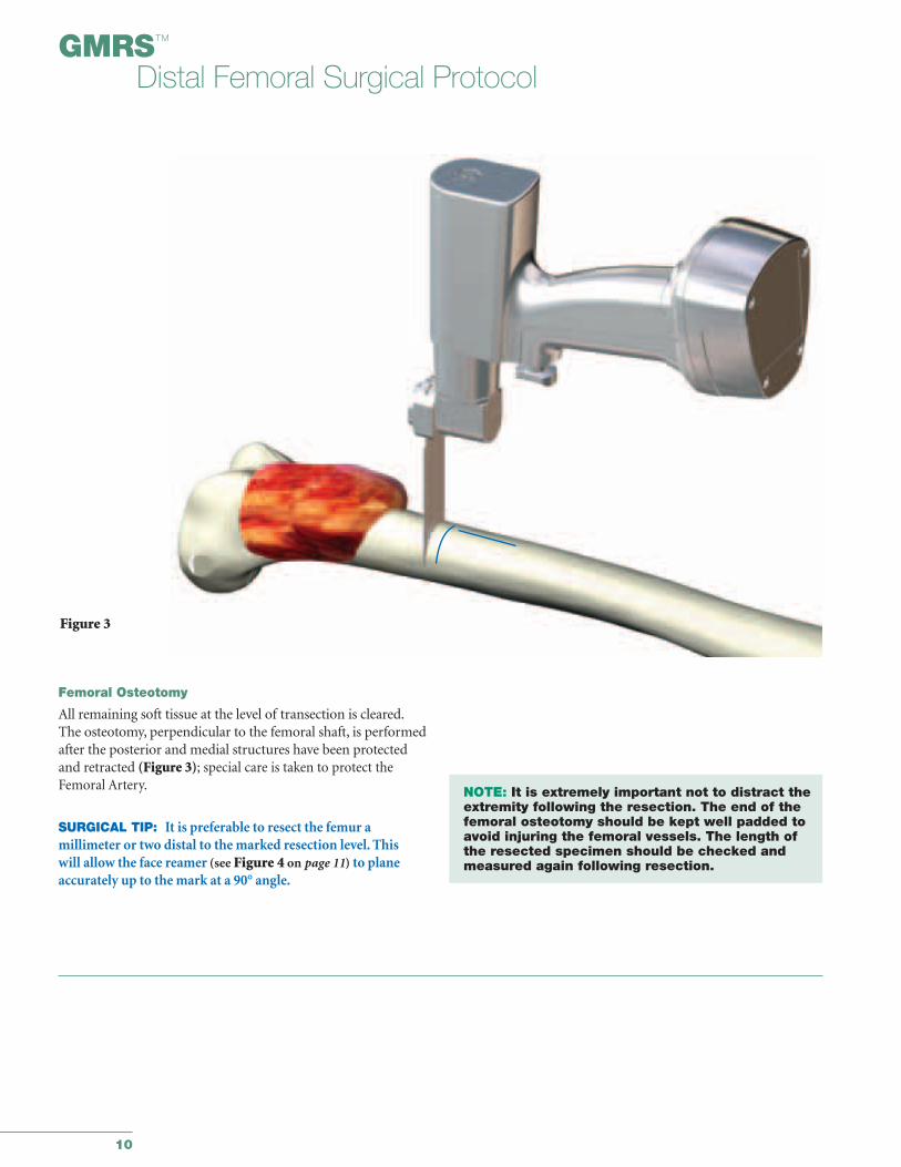
Femoral Osteotomy
All remaining soft tissue at the level of transection is cleared.The osteotomy, perpendicular to the femoral shaft, is performedafter the posterior and medial structures have been protectedand retracted (Figure 3); special care is taken to protect theFemoral Artery.
SURGICAL TIP: It is preferable to resect the femur a millimeter or two distal to the marked resection level. This will allow the face reamer (see Figure 4 on page 11) to planeaccurately up to the mark at a 90° angle.
NOTE: It is extremely important not to distract the extremity following the resection. The end of the femoral osteotomy should be kept well padded to avoid injuring the femoral vessels. The length of the resected specimen should be checked and measured again following resection.
Figure 3
11
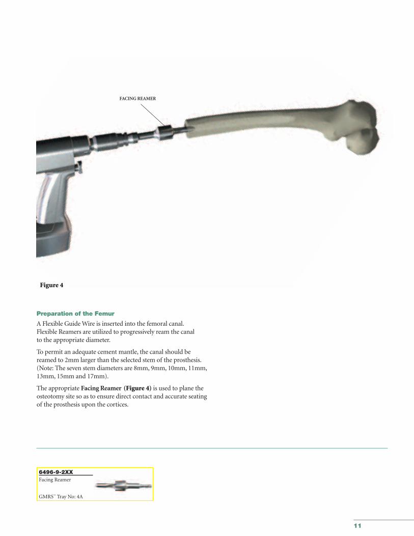
Preparation of the Femur
A Flexible Guide Wire is inserted into the femoral canal.Flexible Reamers are utilized to progressively ream the canal to the appropriate diameter.
To permit an adequate cement mantle, the canal should bereamed to 2mm larger than the selected stem of the prosthesis.(Note: The seven stem diameters are 8mm, 9mm, 10mm, 11mm,13mm, 15mm and 17mm).
The appropriate Facing Reamer (Figure 4) is used to plane theosteotomy site so as to ensure direct contact and accurate seatingof the prosthesis upon the cortices.
6496-9-2XXFacing Reamer
GMRS™ Tray No: 4A
Figure 4
FACING REAMER

GMRS™
Distal Femoral Surgical Protocol
12
The chosen Trial Stem is inserted to evaluate ease of insertionand an appropriate cement mantle. The trial cemented stems are exactly size for size as compared to the implant and do notinclude the cement mantle.
If there is any difficulty inserting the trial stem, continue reaming until the Trial Stem fits freely into the canal, or re-assessthe Trial Stem size. It is extremely important to verify the closeapposition of the seat of the Trial Stem to the cortex.
FLEXIBLE REAMER
15mm 15mm
PMMADISTAL CENTRALIZER
Stem Suggested SeatDiameter Flexible Reamer Diameter
Diameter
Ø 8mm Ø 10mm Ø 22mm
Ø 9mm Ø 11mm Ø 22mm
Ø 10mm Ø 12mm Ø 24mm
Ø 11mm Ø 13mm Ø 24mm
Ø 13mm Ø 15mm Ø 28mm
Ø 15mm Ø 17mm Ø 32mm
Ø 17mm Ø 19mm Ø 36mm
Optional stem centralizers are available for the 10-17mm diameter stems (for the 102mm and 127mm length stems only).The last size Flexible Reamer used corresponds to the diameterof the distal centralizer necessary for correct positioning of thestem tip (Figure 5).
Proximal Tibial Resection
This technique illustrates the preparation for the ModularRotating Hinge Tibial Baseplate which articulates with theGMRS™ Distal Femur. The technique for the Kinematic®
Rotating Hinge All-Poly Tibial Component which also articulates with the GMRS™ Distal Femur, is illustrated inAppendix II. The required proximal tibial cut is neutral to the tibial axis in all planes, i.e. cut in classic alignment with no posterior slope. The amount of bone to be removed, whentaken into consideration with the femoral resection, will reconstruct the pre-operative joint line and leg length.
The instrumentation provides four options for determiningthe resection level of the proximal tibia. The first option illustrates the method for establishing the depth of the tibialcut referenced from intra-medullary trial stem extenders.The other three options can be reviewed in Appendix I.
PMMAFLEXIBLE REAMER DISTAL CENTRALIZER
15mm 15mm
Figure 5
13
6633-9-4XXIM Reamer
IM Reamer Tray R2
6266-5-410T-Handle
IM Reamer Tray R2
6481-1-05XMRH Depth Gauge
IM Reamer Tray R2
6838-7-6733/8" IM Drill
IM Reamer Tray R2
TIBIAL REAMERDEPTHGAUGE
T-HANDLE
IM REAMER
Figure 6b
Figure 6a
DRILL
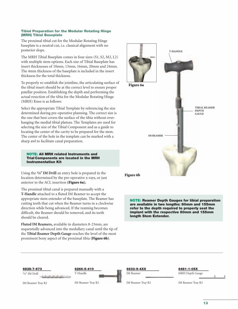
Tibial Preparation for the Modular Rotating Hinge(MRH) Tibial Baseplate
The proximal tibial cut for the Modular Rotating Hinge baseplate is a neutral cut, i.e. classical alignment with no posterior slope.
The MRH Tibial Baseplate comes in four sizes (S1, S2, M2, L2)with multiple stem options. Each size of Tibial Baseplate hasinsert thicknesses of 10mm, 13mm, 16mm, 20mm and 24mm.The 4mm thickness of the baseplate is included in the insertthickness for the total thickness.
To properly re-establish the jointline, the articulating surface ofthe tibial insert should be at the correct level to ensure properpatellar position. Establishing the depth and performing theactual resection of the tibia for the Modular Rotating Hinge(MRH) Knee is as follows:
Select the appropriate Tibial Template by referencing the sizedetermined during pre-operative planning. The correct size isthe one that best covers the surface of the tibia without over-hanging the medial tibial plateau. The Templates are used forselecting the size of the Tibial Component and as a guide tolocating the center of the cavity to be prepared for the stem.The center of the hole in the template can be marked with asharp awl to facilitate canal preparation.
NOTE: All MRH related Instruments and Trial Components are located in the MRH Instrumentation Kit
Using the 3/8" IM Drill an entry hole is prepared in the location determined by the pre-operative x-rays, or just anterior to the ACL insertion (Figure 6a).
The proximal tibial canal is prepared manually with aT-Handle attached to a fluted IM Reamer to accept the appropriate stem extender of the baseplate. The Reamer hascutting teeth that cut when the Reamer turns in a clockwisedirection while being advanced. If the reaming becomes difficult, the Reamer should be removed, and its teeth should be cleared.
Fluted IM Reamers, available in diameters 8-23mm, aresequentially advanced into the medullary canal until the tip ofthe Tibial Reamer Depth Gauge reaches the level of the mostprominent bony aspect of the proximal tibia (Figure 6b).
NOTE: Reamer Depth Gauges for tibial preparation are available in two lengths: 80mm and 155mm refer to the depth required to properly seat the implant with the respective 80mm and 155mm length Stem Extender.
14
GMRS™
Distal Femoral Surgical Protocol
6496-9-051/052Tibial Resection Guide
Trial StemTray R6
8200-0034Support Arm Bracket
Trial Stem Tray R6
6633-9-428Resection GuideTower
Extension GapPrep. Tray R3
6496-9-068Tibial Stylus
Trial StemTray R6
6778-6-XXXTrial Stem Extender
Trial Stem Tray R6
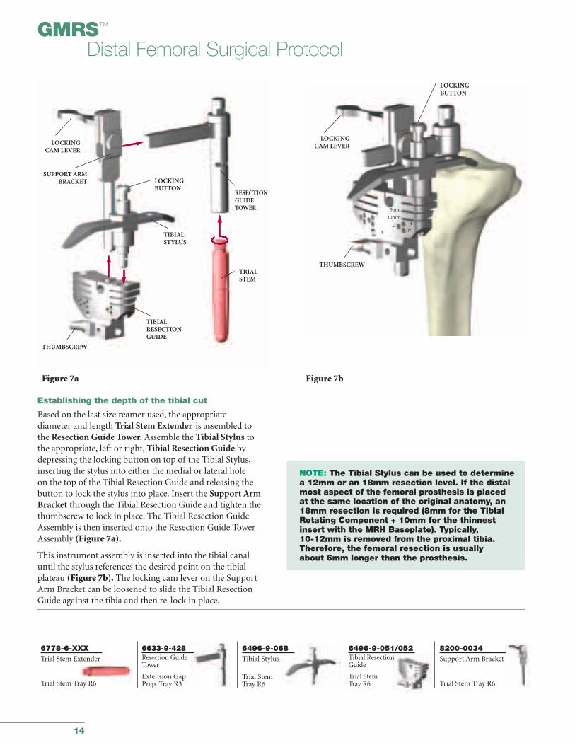
Establishing the depth of the tibial cut
Based on the last size reamer used, the appropriate diameter and length Trial Stem Extender is assembled to the Resection Guide Tower. Assemble the Tibial Stylus to the appropriate, left or right, Tibial Resection Guide bydepressing the locking button on top of the Tibial Stylus,inserting the stylus into either the medial or lateral hole on the top of the Tibial Resection Guide and releasing the button to lock the stylus into place. Insert the Support ArmBracket through the Tibial Resection Guide and tighten thethumbscrew to lock in place. The Tibial Resection GuideAssembly is then inserted onto the Resection Guide TowerAssembly (Figure 7a).
This instrument assembly is inserted into the tibial canaluntil the stylus references the desired point on the tibialplateau (Figure 7b). The locking cam lever on the SupportArm Bracket can be loosened to slide the Tibial ResectionGuide against the tibia and then re-lock in place.
NOTE: The Tibial Stylus can be used to determinea 12mm or an 18mm resection level. If the distalmost aspect of the femoral prosthesis is placedat the same location of the original anatomy, an18mm resection is required (8mm for the TibialRotating Component + 10mm for the thinnestinsert with the MRH Baseplate). Typically, 10-12mm is removed from the proximal tibia.Therefore, the femoral resection is usually about 6mm longer than the prosthesis.
Figure 7bFigure 7a
LOCKINGCAM LEVER
SUPPORT ARMBRACKET
THUMBSCREW
TIBIALRESECTIONGUIDE
TIBIALSTYLUS
LOCKINGCAM LEVER
THUMBSCREW
LOCKINGBUTTON
LOCKINGBUTTON
RESECTIONGUIDETOWER
TRIALSTEM
5mm
10mm
-2 -4
NX
15
6633-7-605Pin Puller
Extension GapPrep Tray R3
5800-4-1251/8" Drill Pin
Extension GapPrep Tray R3
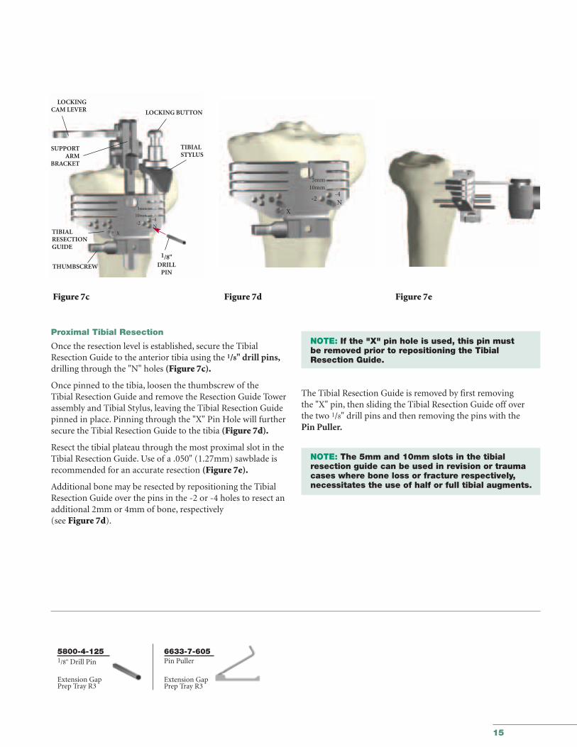
Proximal Tibial Resection
Once the resection level is established, secure the TibialResection Guide to the anterior tibia using the 1/8" drill pins,drilling through the "N" holes (Figure 7c).
Once pinned to the tibia, loosen the thumbscrew of the Tibial Resection Guide and remove the Resection Guide Towerassembly and Tibial Stylus, leaving the Tibial Resection Guidepinned in place. Pinning through the "X" Pin Hole will furthersecure the Tibial Resection Guide to the tibia (Figure 7d).
Resect the tibial plateau through the most proximal slot in theTibial Resection Guide. Use of a .050" (1.27mm) sawblade isrecommended for an accurate resection (Figure 7e).
Additional bone may be resected by repositioning the TibialResection Guide over the pins in the -2 or -4 holes to resect anadditional 2mm or 4mm of bone, respectively (see Figure 7d).
NOTE: If the "X" pin hole is used, this pin must be removed prior to repositioning the Tibial Resection Guide.
The Tibial Resection Guide is removed by first removing the "X" pin, then sliding the Tibial Resection Guide off overthe two 1/8" drill pins and then removing the pins with thePin Puller.
NOTE: The 5mm and 10mm slots in the tibial resection guide can be used in revision or trauma cases where bone loss or fracture respectively, necessitates the use of half or full tibial augments.
Figure 7c Figure 7d Figure 7e
LOCKINGCAM LEVER
SUPPORTARM
BRACKET
LOCKING BUTTON
TIBIALRESECTIONGUIDE
TIBIALSTYLUS
THUMBSCREW
5mm10mm
-2-4N
X
1/8"DRILL
PIN
5mm
10mm
-2-4
X
N
16
GMRS™
Distal Femoral Surgical Protocol
6481-8-520Tibial Stem Boss Reamer
6838-7-2XOAlignment RodExtension GapPreparationTray R3
6633-9-900Stem Boss ReamerBushing
6633-9-910Neutral Bushing
Tibial PreparationTray R8
6633-9-8XXTibial Template
Tibial PreparationTray R8
6778-6-XXXTrial StemExtender
6633-9-426Stem Extender Rod
Tibial PreparationTray R8 Trial Stem Tray R6
6633-9-861AlignmentReamer Guide
6633-7-250Alignment Handle
Extension GapPreparation Tray R3
MRH Instrument Tray H1
MRH Instrument Tray H1MRH Instrument Tray H1
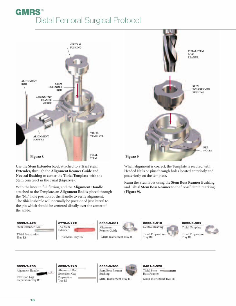
Use the Stem Extender Rod, attached to a Trial StemExtender, through the Alignment Reamer Guide and Neutral Bushing to center the Tibial Template with the Stem construct in the canal (Figure 8).
With the knee in full flexion, and the Alignment Handleattached to the Template, an Alignment Rod is placed throughthe "NT" hole position of the Handle to verify alignment.The tibial tubercle will normally be positioned just lateral tothe pin which should be centered distally over the center ofthe ankle.
When alignment is correct, the Template is secured withHeaded Nails or pins through holes located anteriorly andposteriorly on the template.
Ream the Stem Boss using the Stem Boss Reamer Bushingand Tibial Stem Boss Reamer to the "Boss" depth marking (Figure 9).
Figure 8
NEUTRALBUSHING
ALIGNMENTROD STEM
EXTENDERROD
ALIGNMENTREAMER
GUIDE
ALIGNMENTHANDLE
TIBIAL TEMPLATE
TRIALSTEM Figure 9
TIBIAL STEMBOSSREAMER
STEMBOSS REAMERBUSHING
PINHOLES
17
6633-7-3XXStem Punch
Tibial PrepTray R8
6633-9-86XStem Punch Guide
Tibial PrepTray R8
Figure 11
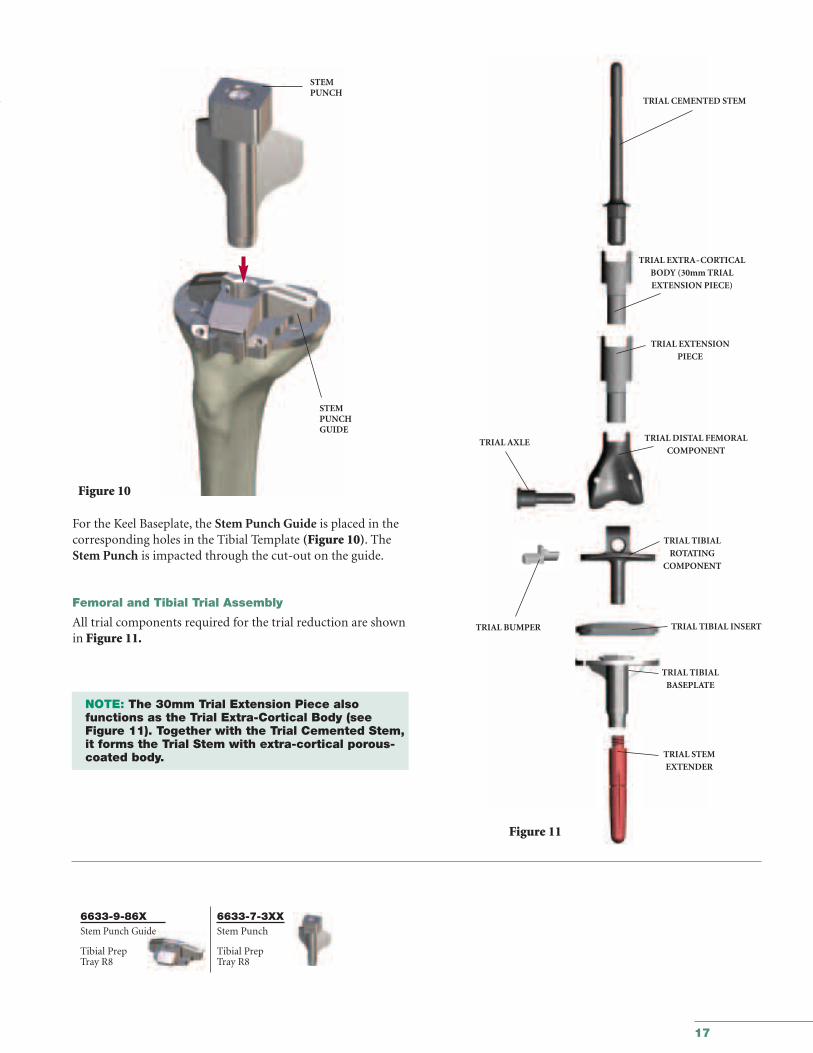
For the Keel Baseplate, the Stem Punch Guide is placed in thecorresponding holes in the Tibial Template (Figure 10). TheStem Punch is impacted through the cut-out on the guide.
Femoral and Tibial Trial Assembly
All trial components required for the trial reduction are shownin Figure 11.
NOTE: The 30mm Trial Extension Piece also functions as the Trial Extra-Cortical Body (see Figure 11). Together with the Trial Cemented Stem,it forms the Trial Stem with extra-cortical porous-coated body.
STEMPUNCH
STEMPUNCHGUIDE
Figure 10
TRIAL CEMENTED STEM
TRIAL EXTRA-CORTICAL
BODY (30mm TRIAL
EXTENSION PIECE)
TRIAL EXTENSION
PIECE
TRIAL DISTAL FEMORAL
COMPONENT
TRIAL TIBIAL
ROTATING
COMPONENT
TRIAL TIBIAL INSERT
TRIAL TIBIAL
BASEPLATE
TRIAL AXLE
TRIAL BUMPER
TRIAL STEM
EXTENDER
18
GMRS™
Distal Femoral Surgical Protocol
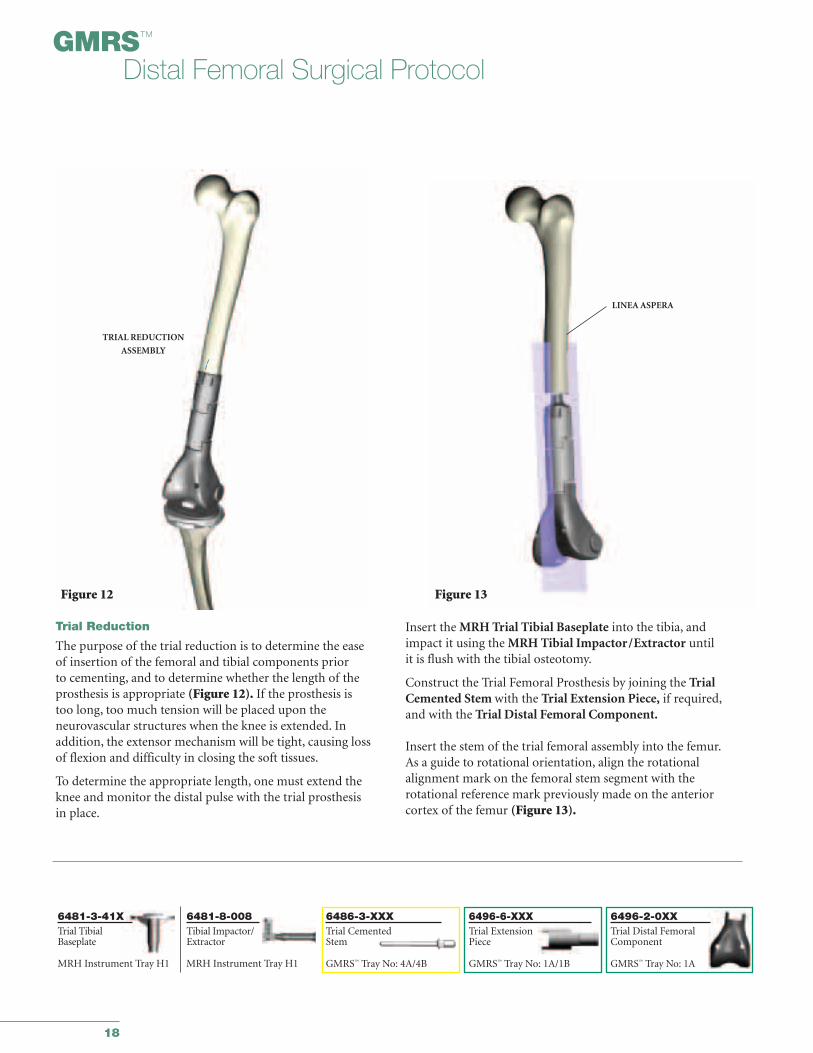
Trial Reduction
The purpose of the trial reduction is to determine the ease of insertion of the femoral and tibial components prior to cementing, and to determine whether the length of the prosthesis is appropriate (Figure 12). If the prosthesis is too long, too much tension will be placed upon the neurovascular structures when the knee is extended. In addition, the extensor mechanism will be tight, causing lossof flexion and difficulty in closing the soft tissues.
To determine the appropriate length, one must extend theknee and monitor the distal pulse with the trial prosthesis in place.
Insert the MRH Trial Tibial Baseplate into the tibia, andimpact it using the MRH Tibial Impactor/Extractor until it is flush with the tibial osteotomy.
Construct the Trial Femoral Prosthesis by joining the TrialCemented Stem with the Trial Extension Piece, if required,and with the Trial Distal Femoral Component.
Insert the stem of the trial femoral assembly into the femur.As a guide to rotational orientation, align the rotational alignment mark on the femoral stem segment with the rotational reference mark previously made on the anterior cortex of the femur (Figure 13).
TRIAL REDUCTION
ASSEMBLY
Figure 12
LINEA ASPERA
Figure 13
6481-3-41XTrial TibialBaseplate
MRH Instrument Tray H1
6481-8-008Tibial Impactor/Extractor
6496-6-XXXTrial ExtensionPiece
GMRS™ Tray No: 1A/1B
6496-2-0XXTrial Distal FemoralComponent
GMRS™ Tray No: 1A
6486-3-XXXTrial CementedStem
GMRS™ Tray No: 4A/4BMRH Instrument Tray H1
19
6496-2-115Trial Axle
GMRS™ Tray No: 1A
6496-3-602Trial Standard TibialRotating Component
GMRS™ Tray No: 1A
6496-2-130/133Trial Bumper
GMRS™ Tray No: 1A
6481-3-XXXTrial Tibial Insert
MRH Instrument Tray No: 2
SURGICAL TIP: As an aid in checking leg length, the distance between the leg-length reference marks on the tibiaand femur can now be rechecked (see Figure 1c, page 8)
If it is determined that the prosthetic construct is too long, thelength of the distal femoral bone resected should be recheckedagainst the length of the assembled prosthesis. If the prosthesisis too long, either additional bone can be removed from thefemur, the length of the prosthesis can be adjusted, or a thinnerinsert can be evaluated.
If the surgeon feels that removing additional bone from thefemur or shortening the femoral prosthesis will have a negativeeffect on patellar tracking, additional bone must be removedfrom the tibial side.
A final test of the range of motion of the knee with the patellatracking in place is then performed. If the patella will be resurfaced, this must be done with the patellar trial in place.A full range of motion should be obtained. Note whether the capsular mechanism can be closed. These factors, takentogether, will determine the adequacy of the length of theresection.
The two most important factors in accepting final length are:
1. Proper Patellar tracking
2. Distal pulses
The decision can now be made if a gastrocnemius flap or muscle transfer will be required, dependent upon the presenceor absence of the capsule or portions of the quadriceps.
TRIALTIBIAL
ROTATINGCOMPONENT
TRIALAXLE
TRIALTIBIALINSERT
TRIALBUMPER
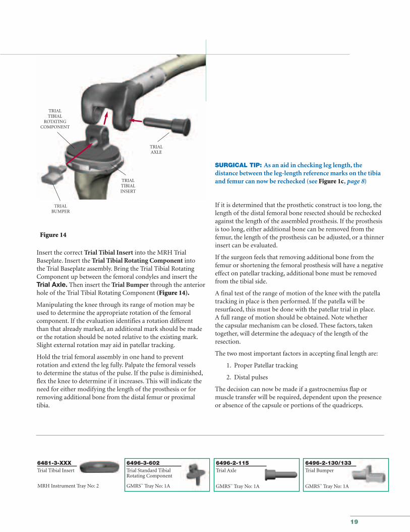
Insert the correct Trial Tibial Insert into the MRH TrialBaseplate. Insert the Trial Tibial Rotating Component into the Trial Baseplate assembly. Bring the Trial Tibial RotatingComponent up between the femoral condyles and insert theTrial Axle. Then insert the Trial Bumper through the anteriorhole of the Trial Tibial Rotating Component (Figure 14).
Manipulating the knee through its range of motion may beused to determine the appropriate rotation of the femoralcomponent. If the evaluation identifies a rotation differentthan that already marked, an additional mark should be madeor the rotation should be noted relative to the existing mark.Slight external rotation may aid in patellar tracking.
Hold the trial femoral assembly in one hand to prevent rotation and extend the leg fully. Palpate the femoral vessels to determine the status of the pulse. If the pulse is diminished,flex the knee to determine if it increases. This will indicate theneed for either modifying the length of the prosthesis or forremoving additional bone from the distal femur or proximaltibia.
Figure 14
20
GMRS™
Distal Femoral Surgical Protocol
8200-0105All-in-one Wrench
MRH InstrumentTray H2
6633-9-986Torque Wrench
MRH InstrumentTray H2
6632-7-010Counter Wrench
Tibial Prep Tray R8
Figure 15
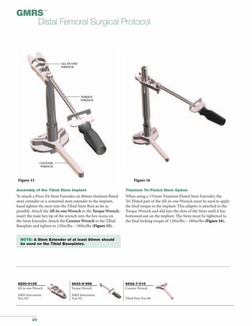
Assembly of the Tibial Stem Implant
To attach a Press-Fit Stem Extender, an 80mm titanium flutedstem extender or a cemented stem extender to the implant,hand tighten the stem into the Tibial Stem Boss as far as possible. Attach the All-in-one Wrench to the Torque Wrench,insert the male hex tip of the wrench into the hex recess on the Stem Extender. Attach the Counter Wrench to the TibialBaseplate and tighten to 120in/lbs – 180in/lbs (Figure 15).
NOTE: A Stem Extender of at least 80mm should be used on the Tibial Baseplates.
Figure 16
ALL-IN-ONEWRENCH
Titanium Tri-Fluted Stem Option
When using a 155mm Titanium Fluted Stem Extender, the Tri-Fluted part of the All-in-one Wrench must be used to applythe final torque to the implant. This adapter is attached to theTorque Wrench and slid into the slots of the Stem until it hasbottomed out on the implant. The Stem must be tightened tothe final locking torque of 120in/lbs – 180in/lbs (Figure 16).
TORQUEWRENCH
COUNTERWRENCH
21
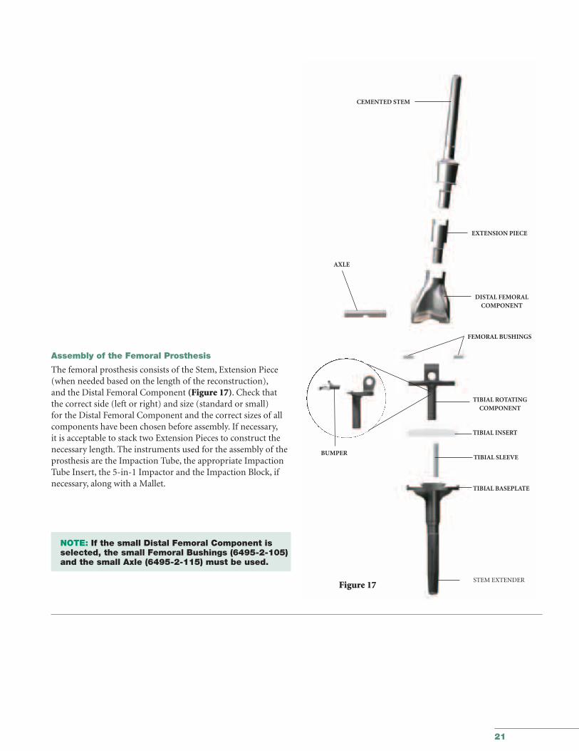
Assembly of the Femoral Prosthesis
The femoral prosthesis consists of the Stem, Extension Piece(when needed based on the length of the reconstruction),and the Distal Femoral Component (Figure 17). Check thatthe correct side (left or right) and size (standard or small) for the Distal Femoral Component and the correct sizes of allcomponents have been chosen before assembly. If necessary,it is acceptable to stack two Extension Pieces to construct thenecessary length. The instruments used for the assembly of theprosthesis are the Impaction Tube, the appropriate ImpactionTube Insert, the 5-in-1 Impactor and the Impaction Block, ifnecessary, along with a Mallet.
NOTE: If the small Distal Femoral Component is selected, the small Femoral Bushings (6495-2-105) and the small Axle (6495-2-115) must be used.
CEMENTED STEM
EXTENSION PIECE
DISTAL FEMORAL COMPONENT
FEMORAL BUSHINGS
TIBIAL ROTATINGCOMPONENT
TIBIAL SLEEVE
TIBIAL INSERT
TIBIAL BASEPLATE
STEM EXTENDER
AXLE
Figure 17
BUMPER
22
GMRS™
Distal Femoral Surgical Protocol
6496-9-065/066Impaction TubeInsert
GMRS™ TrayNo: 4A
6496-9-0635-in-1 Impactor
GMRS™ Tray No: 3
6496-9-053Impaction Tube
GMRS™ Tray No: 4A
6496-9-064ImpactionSupport Block
GMRS™ Tray No: 1A
5235-2-520Mallet
GMRS™ Tray No: 3
IMPACTION TUBE
INSERT
IMPACTIONTUBE
Figure 18a
Figure 18b
5-IN-1IMPACTOR/WRENCH
Figure 19b
Figure 19a
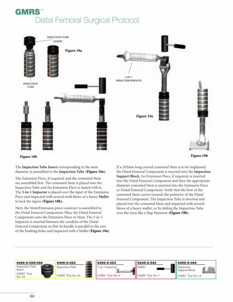
The Impaction Tube Insert corresponding to the stem diameter is assembled to the Impaction Tube (Figure 18a).
The Extension Piece, if required, and the cemented Stem are assembled first. The cemented Stem is placed into theImpaction Tube and the Extension Piece is mated with it.The 5-in-1 Impactor is placed over the taper of the ExtensionPiece and impacted with several swift blows of a heavy Malletto lock the tapers (Figure 18b).
Next, the Stem/Extension piece construct is assembled to the Distal Femoral Component. Place the Distal FemoralComponent onto the Extension Piece or Stem. The 5-in-1Impactor is inserted between the condyles of the DistalFemoral Component so that its handle is parallel to the axis of the bushing holes and impacted with a Mallet (Figure 19a).
If a 203mm long curved cemented Stem is to be implanted,the Distal Femoral Component is inserted into the ImpactionSupport Block. An Extension Piece, if required, is inserted into the Distal Femoral Component and then the appropriatediameter cemented Stem is inserted into the Extension Piece or Distal Femoral Component. Verify that the bow of thecemented Stem curves towards the posterior of the DistalFemoral Component. The Impaction Tube is inverted andplaced over the cemented Stem and impacted with severalblows of a heavy mallet, or by sliding the Impaction Tube over the stem like a Slap Hammer (Figure 19b).
23
SURGICAL TIP: If a stem centralizer is not being used,plug the hole in the stem with bone cement.
The prosthesis is then inserted into the femoral canal untilthe stem seat is flush with the host bone at the osteotomy site.Excess cement is removed from around the prosthesis. Care istaken to prevent cement from getting into the Extra-Medullary porous-coated section. It is firmly held in place atthe rotational orientation determined by the trial reductionwhile the cement cures.
Implantation and Orientation of the Tibial and Femoral Prostheses
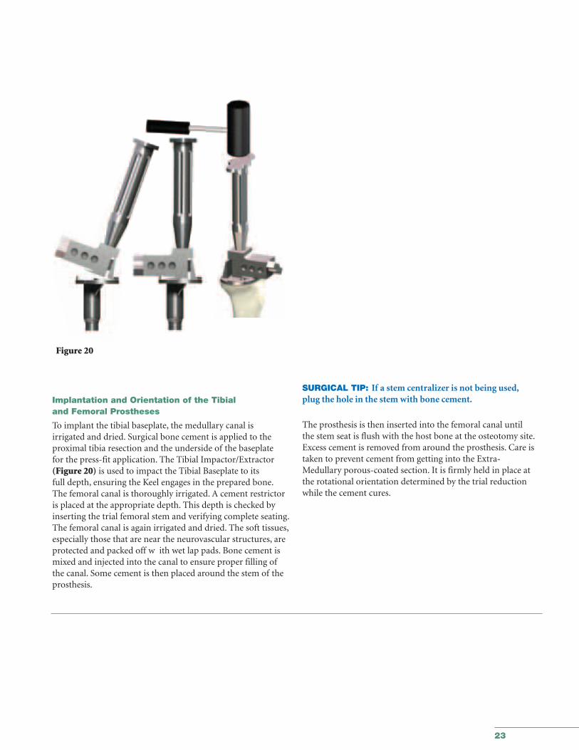
To implant the tibial baseplate, the medullary canal is irrigated and dried. Surgical bone cement is applied to theproximal tibia resection and the underside of the baseplate for the press-fit application. The Tibial Impactor/Extractor(Figure 20) is used to impact the Tibial Baseplate to its full depth, ensuring the Keel engages in the prepared bone.The femoral canal is thoroughly irrigated. A cement restrictoris placed at the appropriate depth. This depth is checked byinserting the trial femoral stem and verifying complete seating.The femoral canal is again irrigated and dried. The soft tissues,especially those that are near the neurovascular structures, areprotected and packed off w ith wet lap pads. Bone cement ismixed and injected into the canal to ensure proper filling ofthe canal. Some cement is then placed around the stem of theprosthesis.
Figure 20
24
GMRS™
Distal Femoral Surgical Protocol
Figure 21 Figure 22
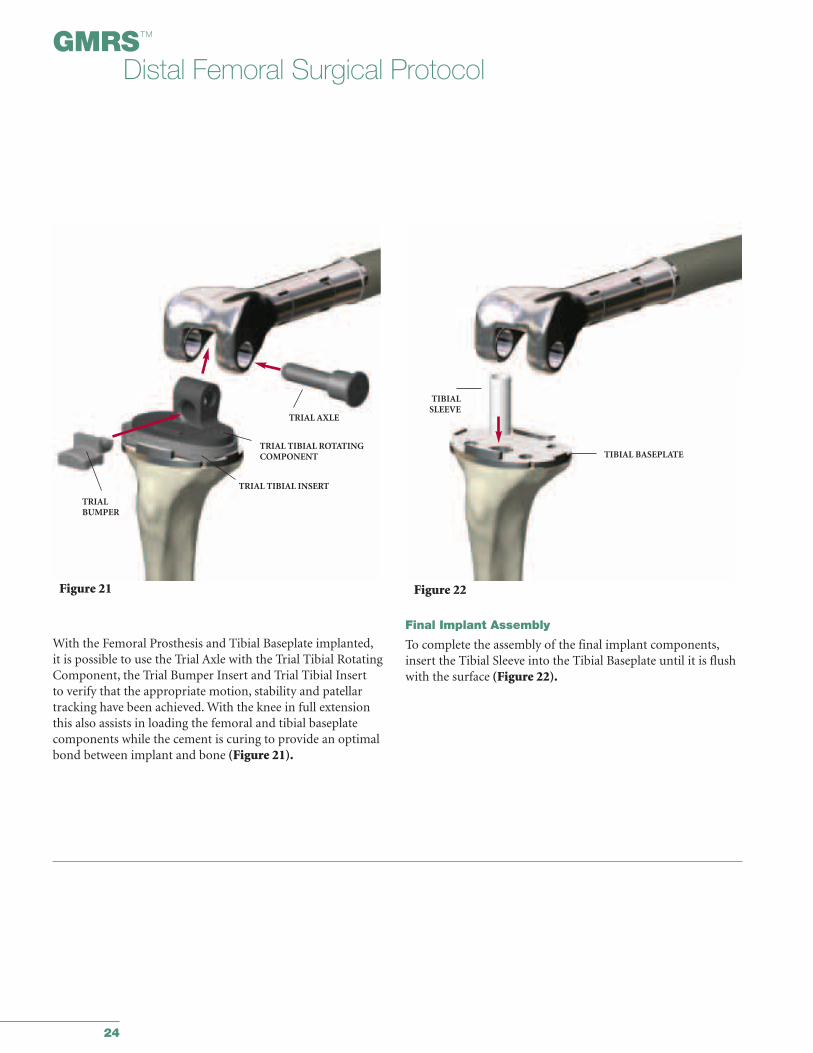
With the Femoral Prosthesis and Tibial Baseplate implanted,it is possible to use the Trial Axle with the Trial Tibial RotatingComponent, the Trial Bumper Insert and Trial Tibial Insert to verify that the appropriate motion, stability and patellartracking have been achieved. With the knee in full extensionthis also assists in loading the femoral and tibial baseplate components while the cement is curing to provide an optimalbond between implant and bone (Figure 21).
Final Implant Assembly
To complete the assembly of the final implant components,insert the Tibial Sleeve into the Tibial Baseplate until it is flushwith the surface (Figure 22).
TRIAL AXLE
TRIAL TIBIAL ROTATINGCOMPONENT
TRIAL TIBIAL INSERT
TRIALBUMPER
TIBIALSLEEVE
TIBIAL BASEPLATE
25
Figure 23a
TIBIALINSERT
Figure 23c
AXLE
BUMPER HOLE
BUMPER INSERT
Figure 23b
FEMORALBUSHINGS
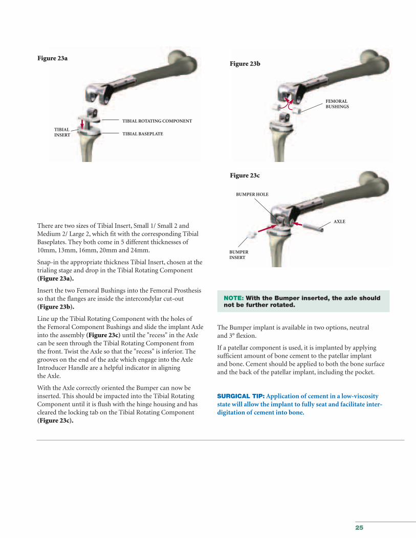
There are two sizes of Tibial Insert, Small 1/ Small 2 andMedium 2/ Large 2, which fit with the corresponding TibialBaseplates. They both come in 5 different thicknesses of10mm, 13mm, 16mm, 20mm and 24mm.
Snap-in the appropriate thickness Tibial Insert, chosen at thetrialing stage and drop in the Tibial Rotating Component(Figure 23a).
Insert the two Femoral Bushings into the Femoral Prosthesisso that the flanges are inside the intercondylar cut-out(Figure 23b).
Line up the Tibial Rotating Component with the holes ofthe Femoral Component Bushings and slide the implant Axleinto the assembly (Figure 23c) until the "recess" in the Axlecan be seen through the Tibial Rotating Component from the front. Twist the Axle so that the "recess" is inferior. Thegrooves on the end of the axle which engage into the AxleIntroducer Handle are a helpful indicator in aligning the Axle.
With the Axle correctly oriented the Bumper can now beinserted. This should be impacted into the Tibial RotatingComponent until it is flush with the hinge housing and hascleared the locking tab on the Tibial Rotating Component(Figure 23c).
NOTE: With the Bumper inserted, the axle should not be further rotated.
The Bumper implant is available in two options, neutral and 3° flexion.
If a patellar component is used, it is implanted by applyingsufficient amount of bone cement to the patellar implant and bone. Cement should be applied to both the bone surfaceand the back of the patellar implant, including the pocket.
SURGICAL TIP: Application of cement in a low-viscositystate will allow the implant to fully seat and facilitate inter-digitation of cement into bone.
TIBIAL BASEPLATE
TIBIAL ROTATING COMPONENT

26
27
Orthopaedics
GMRS™ Distal FemoralSurgical Protocol
Appendices
Appendix IEstablishing the Depth of the Tibial Cut 28
Appendix IITibial Preparation for the
All-Poly Tibial Component 40
Appendix IIITaper Disassembly 46
28
GMRS™
Distal Femoral Surgical Protocol
6496-9-057Tibial ResectionLevel Indicator
GMRS™ Tray No: 1A
6496-9-051/052TibialResectionGuideGMRS™ Tray No: 8A
8mm
11mm
21mm
16mm
6633-7-250AlignmentHandle
GMRS™ Tray No: 8B
6838-7-230Long Alignment Pin
GMRS™ Tray No: 8B
6496-2-0XXTrial DistalFemoralComponentGMRS™ Tray No: 1A
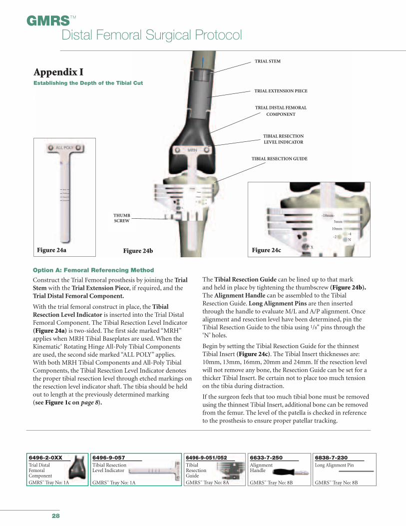
Option A: Femoral Referencing Method
Construct the Trial Femoral prosthesis by joining the TrialStem with the Trial Extension Piece, if required, and theTrial Distal Femoral Component.
With the trial femoral construct in place, the TibialResection Level Indicator is inserted into the Trial DistalFemoral Component. The Tibial Resection Level Indicator(Figure 24a) is two-sided. The first side marked “MRH”applies when MRH Tibial Baseplates are used. When theKinematic® Rotating Hinge All-Poly Tibial Components are used, the second side marked “ALL POLY” applies.With both MRH Tibial Components and All-Poly TibialComponents, the Tibial Resection Level Indicator denotesthe proper tibial resection level through etched markings onthe resection level indicator shaft. The tibia should be heldout to length at the previously determined marking (see Figure 1c on page 8).
The Tibial Resection Guide can be lined up to that mark and held in place by tightening the thumbscrew (Figure 24b).The Alignment Handle can be assembled to the TibialResection Guide. Long Alignment Pins are then insertedthrough the handle to evaluate M/L and A/P alignment. Oncealignment and resection level have been determined, pin theTibial Resection Guide to the tibia using 1/8" pins through the‘N’ holes.
Begin by setting the Tibial Resection Guide for the thinnestTibial Insert (Figure 24c). The Tibial Insert thicknesses are:10mm, 13mm, 16mm, 20mm and 24mm. If the resection levelwill not remove any bone, the Resection Guide can be set for athicker Tibial Insert. Be certain not to place too much tensionon the tibia during distraction.
If the surgeon feels that too much tibial bone must be removedusing the thinnest Tibial Insert, additional bone can be removedfrom the femur. The level of the patella is checked in referenceto the prosthesis to ensure proper patellar tracking.
Figure 24b
TRIAL STEM
TRIAL EXTENSION PIECE
TRIAL DISTAL FEMORAL
COMPONENT
TIBIAL RESECTION GUIDE
TIBIAL RESECTION LEVEL INDICATOR
10mm
5mm
10mm
X
-2-4
N
-10mm-
5mm
10mm
-2-4
N
XFigure 24c
THUMBSCREW
21mm
Figure 24a
8mm
11mm
16mm
Appendix IEstablishing the Depth of the Tibial Cut
29
Figure 25 Figure 26
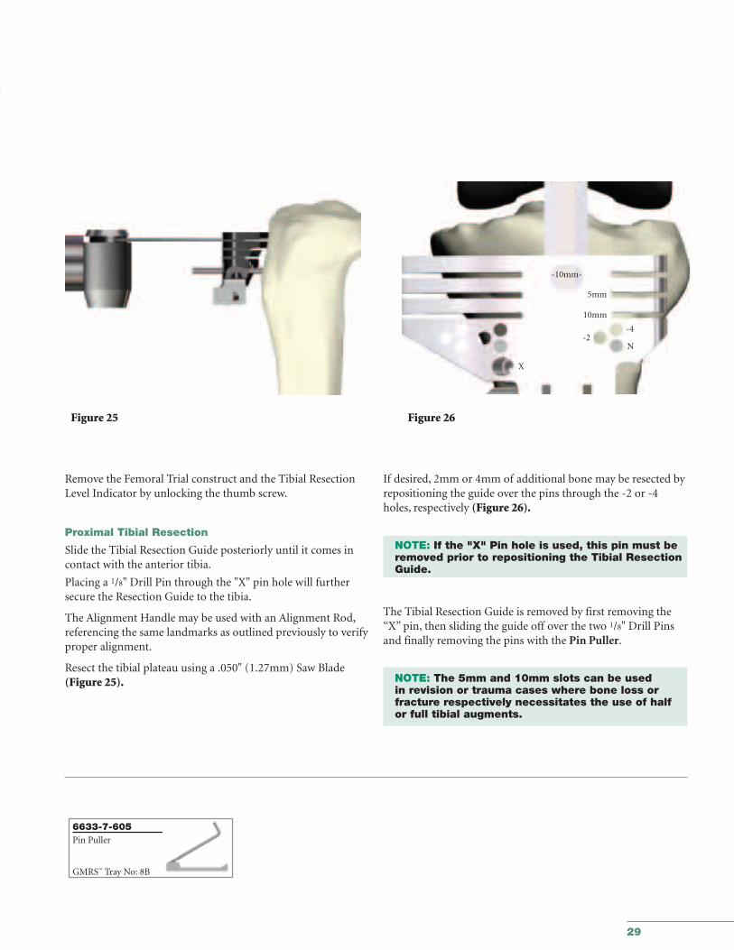
Remove the Femoral Trial construct and the Tibial ResectionLevel Indicator by unlocking the thumb screw.
Proximal Tibial Resection
Slide the Tibial Resection Guide posteriorly until it comes incontact with the anterior tibia.
Placing a 1/8" Drill Pin through the "X" pin hole will furthersecure the Resection Guide to the tibia.
The Alignment Handle may be used with an Alignment Rod,referencing the same landmarks as outlined previously to verifyproper alignment.
Resect the tibial plateau using a .050" (1.27mm) Saw Blade(Figure 25).
If desired, 2mm or 4mm of additional bone may be resected byrepositioning the guide over the pins through the -2 or -4holes, respectively (Figure 26).
NOTE: If the "X" Pin hole is used, this pin must be removed prior to repositioning the Tibial Resection Guide.
The Tibial Resection Guide is removed by first removing the“X” pin, then sliding the guide off over the two 1/8" Drill Pinsand finally removing the pins with the Pin Puller.
NOTE: The 5mm and 10mm slots can be used in revision or trauma cases where bone loss or fracture respectively necessitates the use of half or full tibial augments.
-10mm-
5mm
10mm
-2-4
N
X
6633-7-605Pin Puller
GMRS™ Tray No: 8B
30
GMRS™
Distal Femoral Surgical Protocol
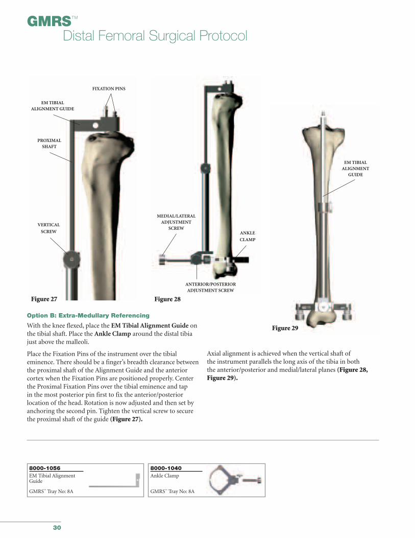
Option B: Extra-Medullary Referencing
With the knee flexed, place the EM Tibial Alignment Guide onthe tibial shaft. Place the Ankle Clamp around the distal tibiajust above the malleoli.
Place the Fixation Pins of the instrument over the tibial eminence. There should be a finger’s breadth clearance betweenthe proximal shaft of the Alignment Guide and the anteriorcortex when the Fixation Pins are positioned properly. Centerthe Proximal Fixation Pins over the tibial eminence and tap in the most posterior pin first to fix the anterior/posterior location of the head. Rotation is now adjusted and then set byanchoring the second pin. Tighten the vertical screw to securethe proximal shaft of the guide (Figure 27).
Axial alignment is achieved when the vertical shaft ofthe instrument parallels the long axis of the tibia in both the anterior/posterior and medial/lateral planes (Figure 28,Figure 29).
Figure 27
Figure 29
PROXIMALSHAFT
VERTICAL
SCREW
FIXATION PINS
EM TIBIALALIGNMENT GUIDE
MEDIAL/LATERALADJUSTMENT
SCREWANKLE
CLAMP
ANTERIOR/POSTERIORADJUSTMENT SCREW
EM TIBIALALIGNMENT
GUIDE
Figure 28
8000-1056EM Tibial AlignmentGuide
GMRS™ Tray No: 8A
8000-1040Ankle Clamp
GMRS™ Tray No: 8A
31
Figure 30 Figure 31
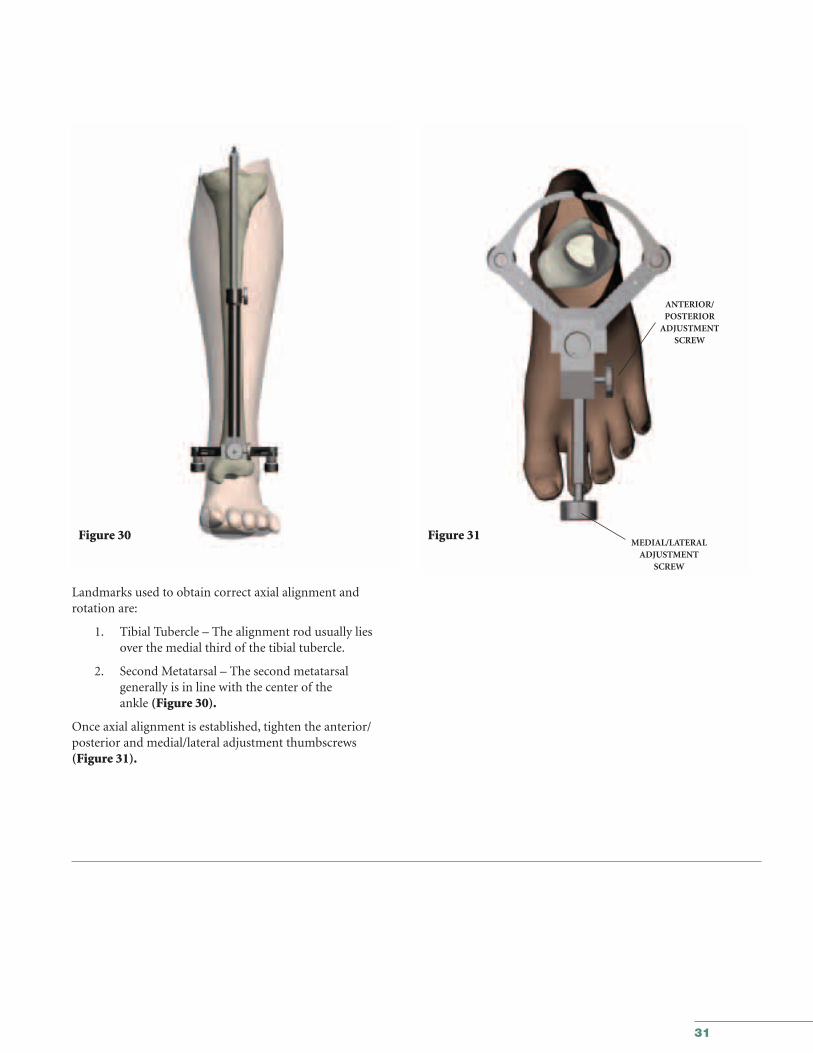
Landmarks used to obtain correct axial alignment and rotation are:
1. Tibial Tubercle – The alignment rod usually lies over the medial third of the tibial tubercle.
2. Second Metatarsal – The second metatarsalgenerally is in line with the center of theankle (Figure 30).
Once axial alignment is established, tighten the anterior/posterior and medial/lateral adjustment thumbscrews (Figure 31).
ANTERIOR/POSTERIOR
ADJUSTMENT SCREW
MEDIAL/LATERALADJUSTMENT
SCREW
32
GMRS™
Distal Femoral Surgical Protocol
Figure 32 Figure 33
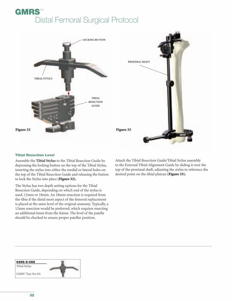
Tibial Resection Level
Assemble the Tibial Stylus to the Tibial Resection Guide bydepressing the locking button on the top of the Tibial Stylus,inserting the stylus into either the medial or lateral holes onthe top of the Tibial Resection Guide and releasing the buttonto lock the Stylus into place (Figure 32).
The Stylus has two depth setting options for the TibialResection Guide, depending on which end of the stylus is used, 12mm or 18mm. An 18mm resection is required fromthe tibia if the distal most aspect of the femoral replacement is placed at the same level of the original anatomy. Typically, a12mm resection would be preferred, which requires resectingan additional 6mm from the femur. The level of the patellashould be checked to ensure proper patellar position.
Attach the Tibial Resection Guide/Tibial Stylus assembly to the External Tibial Alignment Guide by sliding it over thetop of the proximal shaft, adjusting the stylus to reference thedesired point on the tibial plateau (Figure 33).
TIBIAL STYLUS
LOCKING BUTTON
TIBIAL
RESECTION
GUIDE
PROXIMAL SHAFT
6496-9-068Tibial Stylus
GMRS™ Tray No: 8A
33
Figure 34
PROXIMAL
SHAFT
TIBIAL RESECTION GUIDE
VERTICAL THUMB SCREW
Figure 35
Figure 36
TIBIAL RESECTION
GUIDE
10mm
-2-4
N
X
5mm
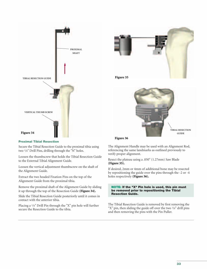
Proximal Tibial Resection
Secure the Tibial Resection Guide to the proximal tibia usingtwo 1/8" Drill Pins, drilling through the "N" holes.
Loosen the thumbscrew that holds the Tibial Resection Guideto the External Tibial Alignment Guide.
Loosen the vertical adjustment thumbscrew on the shaft ofthe Alignment Guide.
Extract the two headed Fixation Pins on the top of theAlignment Guide from the proximal tibia.
Remove the proximal shaft of the Alignment Guide by slidingit up through the top of the Resection Guide (Figure 34).
Slide the Tibial Resection Guide posteriorly until it comes incontact with the anterior tibia.
Placing a 1/8" Drill Pin through the "X" pin hole will furthersecure the Resection Guide to the tibia.
The Alignment Handle may be used with an Alignment Rod,referencing the same landmarks as outlined previously to verify proper alignment.
Resect the plateau using a .050" (1.27mm) Saw Blade (Figure 35).
If desired, 2mm or 4mm of additional bone may be resected by repositioning the guide over the pins through the -2 or -4holes respectively (Figure 36).
NOTE: If the "X" Pin hole is used, this pin must be removed prior to repositioning the Tibial Resection Guide.
The Tibial Resection Guide is removed by first removing the“X” pin, then sliding the guide off over the two 1/8" drill pinsand then removing the pins with the Pin Puller.
34
GMRS™
Distal Femoral Surgical Protocol
Figure 37 Figure 38
DRILL
T-HANDLE
DIAMETER
TRANSITION
POINTIM ROD
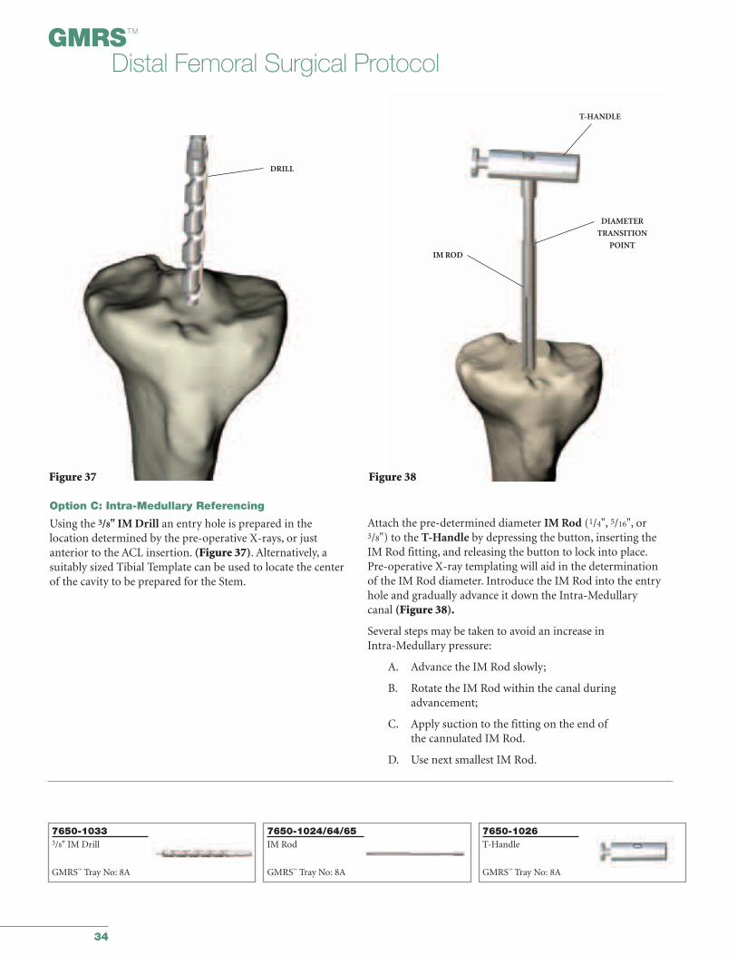
Option C: Intra-Medullary Referencing
Using the 3/8" IM Drill an entry hole is prepared in the location determined by the pre-operative X-rays, or just anterior to the ACL insertion. (Figure 37). Alternatively, a suitably sized Tibial Template can be used to locate the centerof the cavity to be prepared for the Stem.
Attach the pre-determined diameter IM Rod (1/4", 5/16", or3/8") to the T-Handle by depressing the button, inserting theIM Rod fitting, and releasing the button to lock into place.Pre-operative X-ray templating will aid in the determinationof the IM Rod diameter. Introduce the IM Rod into the entryhole and gradually advance it down the Intra-Medullarycanal (Figure 38).
Several steps may be taken to avoid an increase in Intra-Medullary pressure:
A. Advance the IM Rod slowly;
B. Rotate the IM Rod within the canal duringadvancement;
C. Apply suction to the fitting on the end ofthe cannulated IM Rod.
D. Use next smallest IM Rod.
7650-10333/8" IM Drill
GMRS™ Tray No: 8A
7650-1026T-Handle
GMRS™ Tray No: 8A
7650-1024/64/65IM Rod
GMRS™ Tray No: 8A
35
Figure 39
IM ROD
DIAMETER
TRANSITIONPOINT
Figure 40
IM RODHEADED NAIL
IM TIBIAL ALIGNMENTGUIDE
Figure 41
MOUNTING BAR
HEADED NAIL
Figure 42
THUMBSCREWTIBIAL RESECTION
GUIDE
IM TIBIAL ALIGNMENT
GUIDE
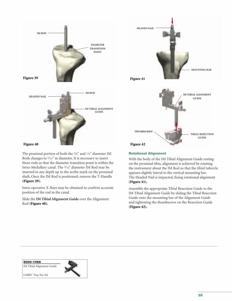
The proximal portion of both the 3/8" and 1/4" diameter IMRods changes to 5/16" in diameter. It is necessary to insertthose rods so that the diameter transition point is within theIntra-Medullary canal. The 5/16" diameter IM Rod may beinserted to any depth up to the scribe mark on the proximalshaft. Once the IM Rod is positioned, remove the T-Handle(Figure 39).
Intra-operative X-Rays may be obtained to confirm accurateposition of the rod in the canal.
Slide the IM Tibial Alignment Guide over the AlignmentRod (Figure 40).
Rotational Alignment
With the body of the IM Tibial Alignment Guide resting on the proximal tibia, alignment is achieved by rotating the instrument about the IM Rod so that the tibial tubercleappears slightly lateral to the vertical mounting bar.The Headed Nail is impacted, fixing rotational alignment(Figure 41).
Assemble the appropriate Tibial Resection Guide to the IM Tibial Alignment Guide by sliding the Tibial ResectionGuide onto the mounting bar of the Alignment Guide and tightening the thumbscrew on the Resection Guide (Figure 42).
8000-1066IM Tibial Alignment Guide
GMRS™ Tray No: 8A
36
GMRS™
Distal Femoral Surgical Protocol
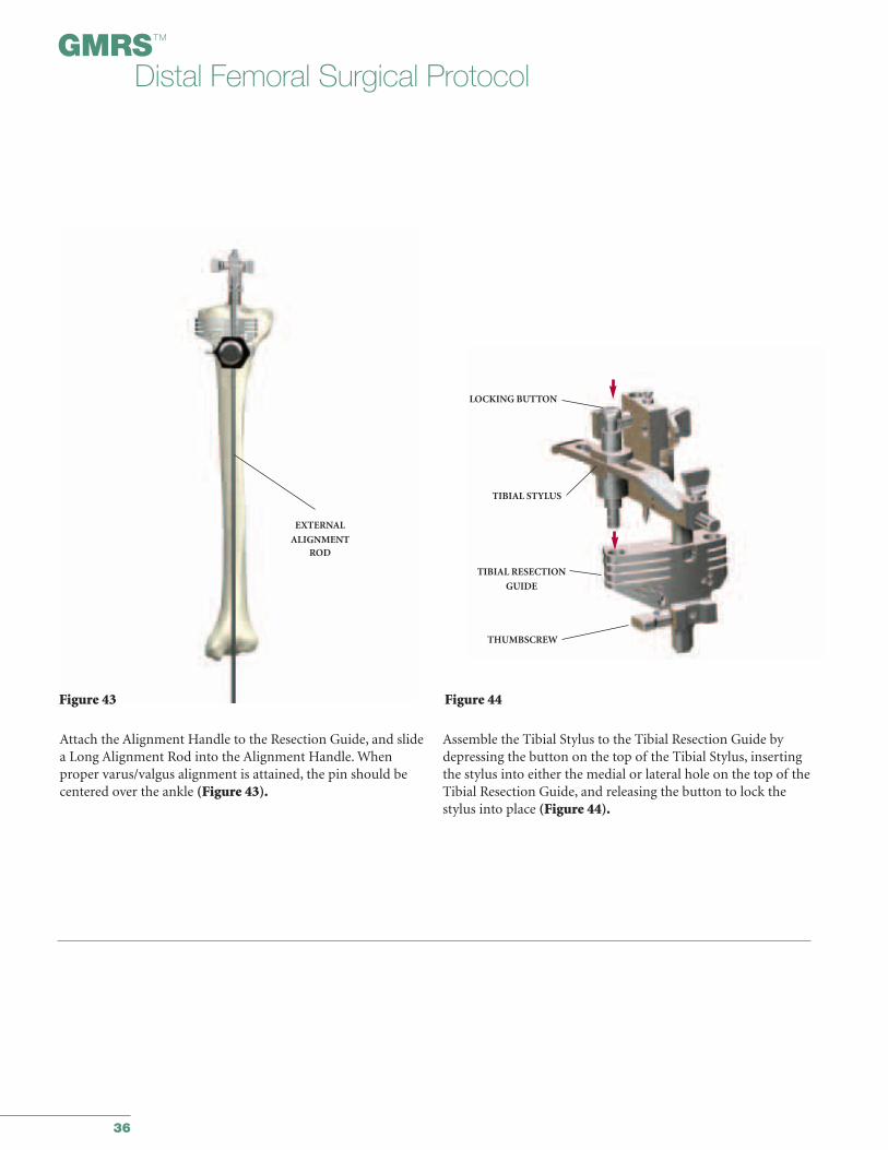
Attach the Alignment Handle to the Resection Guide, and slidea Long Alignment Rod into the Alignment Handle. Whenproper varus/valgus alignment is attained, the pin should becentered over the ankle (Figure 43).
Assemble the Tibial Stylus to the Tibial Resection Guide bydepressing the button on the top of the Tibial Stylus, insertingthe stylus into either the medial or lateral hole on the top of theTibial Resection Guide, and releasing the button to lock thestylus into place (Figure 44).
Figure 43
EXTERNAL
ALIGNMENTROD
Figure 44
LOCKING BUTTON
TIBIAL STYLUS
TIBIAL RESECTION
GUIDE
THUMBSCREW
37
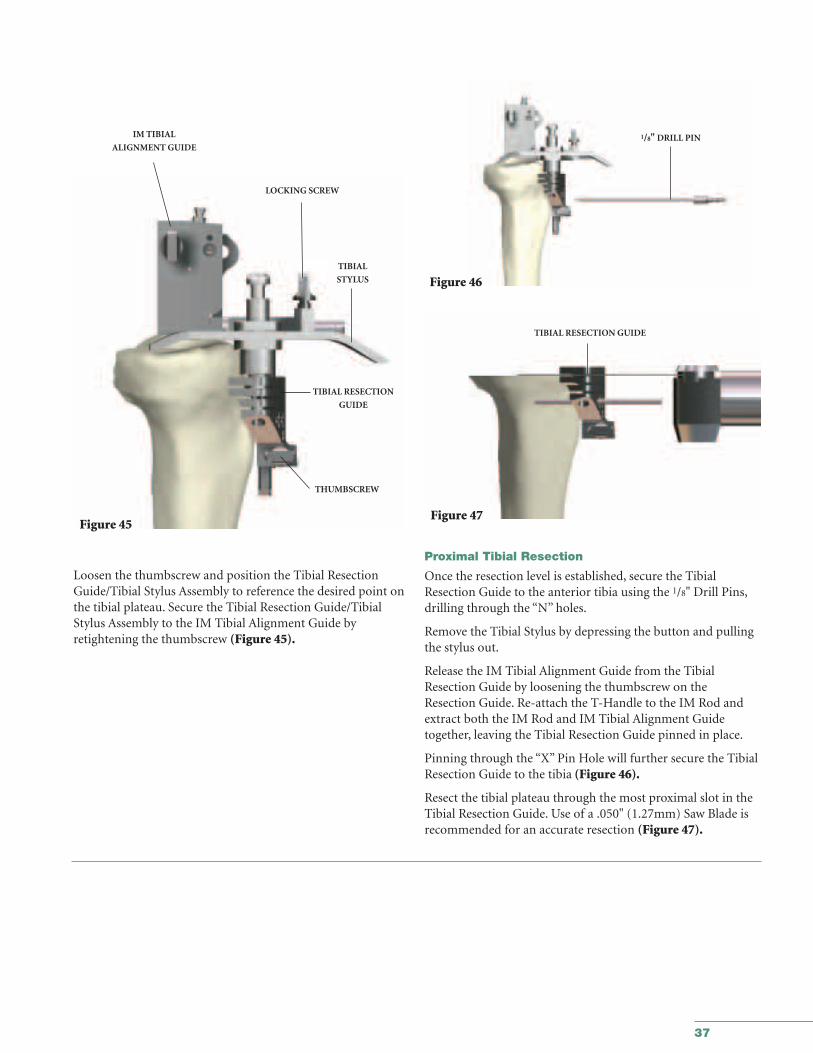
Loosen the thumbscrew and position the Tibial ResectionGuide/Tibial Stylus Assembly to reference the desired point onthe tibial plateau. Secure the Tibial Resection Guide/TibialStylus Assembly to the IM Tibial Alignment Guide by retightening the thumbscrew (Figure 45).
Figure 45
IM TIBIAL
ALIGNMENT GUIDE
LOCKING SCREW
TIBIAL
STYLUS
TIBIAL RESECTION
GUIDE
THUMBSCREW
Figure 46
Figure 47
1/8" DRILL PIN
TIBIAL RESECTION GUIDE
Proximal Tibial Resection
Once the resection level is established, secure the TibialResection Guide to the anterior tibia using the 1/8" Drill Pins,drilling through the “N” holes.
Remove the Tibial Stylus by depressing the button and pullingthe stylus out.
Release the IM Tibial Alignment Guide from the TibialResection Guide by loosening the thumbscrew on theResection Guide. Re-attach the T-Handle to the IM Rod andextract both the IM Rod and IM Tibial Alignment Guidetogether, leaving the Tibial Resection Guide pinned in place.
Pinning through the “X” Pin Hole will further secure the TibialResection Guide to the tibia (Figure 46).
Resect the tibial plateau through the most proximal slot in theTibial Resection Guide. Use of a .050" (1.27mm) Saw Blade isrecommended for an accurate resection (Figure 47).
38
GMRS™
Distal Femoral Surgical Protocol
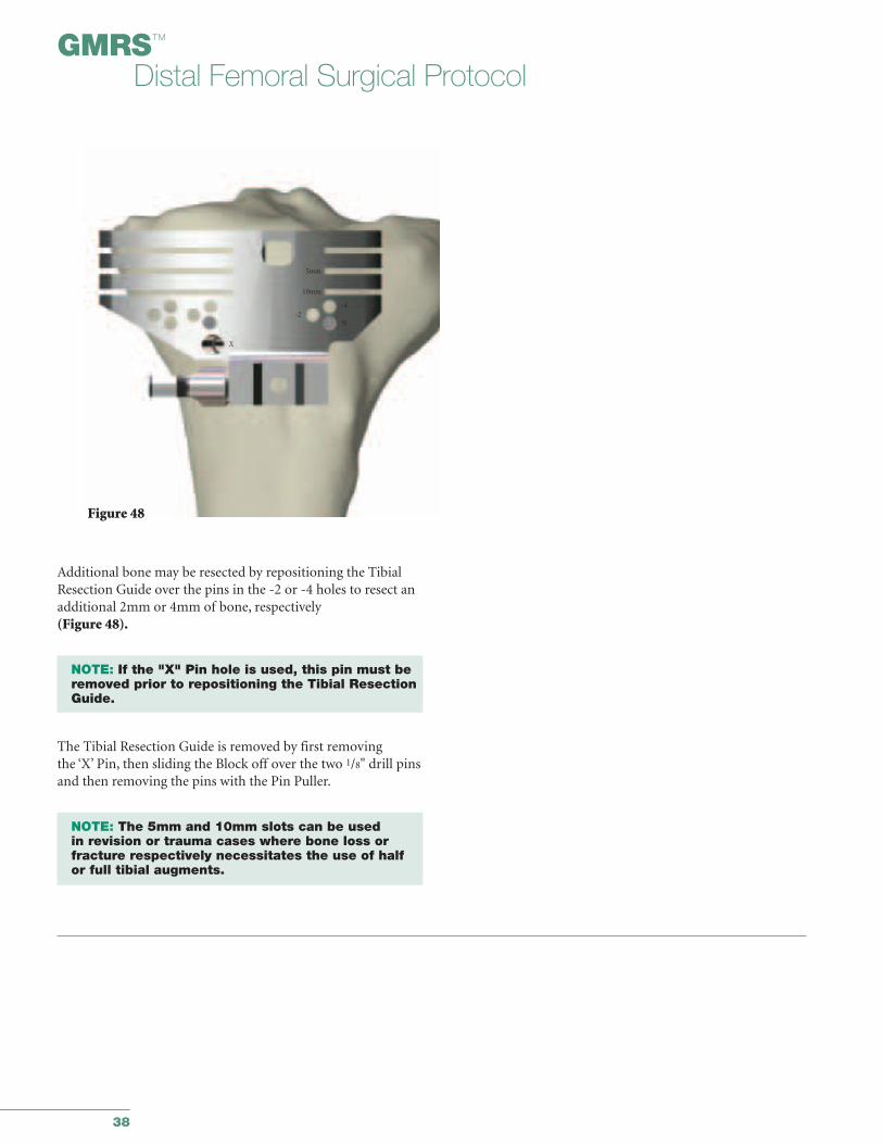
Additional bone may be resected by repositioning the TibialResection Guide over the pins in the -2 or -4 holes to resect anadditional 2mm or 4mm of bone, respectively (Figure 48).
NOTE: If the "X" Pin hole is used, this pin must beremoved prior to repositioning the Tibial Resection Guide.
The Tibial Resection Guide is removed by first removing the ‘X’ Pin, then sliding the Block off over the two 1/8" drill pinsand then removing the pins with the Pin Puller.
NOTE: The 5mm and 10mm slots can be used in revision or trauma cases where bone loss orfracture respectively necessitates the use of half or full tibial augments.
Figure 48
-4-2
N
X
5mm
10mm

39
APPENDIX IITibial Preparation for the All-Poly Tibial Component
40
GMRS™
Distal Femoral Surgical Protocol
ALIGNMENT HANDLE
1/8" DRILL
PIN
LONG ALIGNMENT
PIN
Figure 49
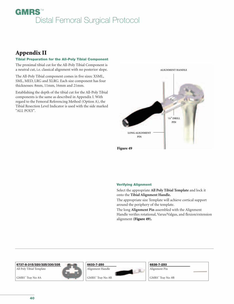
Verifying Alignment
Select the appropriate All Poly Tibial Template and lock itonto the Tibial Alignment Handle.The appropriate size Template will achieve cortical supportaround the periphery of the template.
The long Alignment Pin assembled with the AlignmentHandle verifies rotational, Varus/Valgus, and flexion/extensionalignment (Figure 49).
Appendix IITibial Preparation for the All-Poly Tibial Component
The proximal tibial cut for the All-Poly Tibial Component is a neutral cut, i.e. classical alignment with no posterior slope.
The All-Poly Tibial component comes in five sizes: XSML,SML, MED, LRG and XLRG. Each size component has fourthicknesses: 8mm, 11mm, 16mm and 21mm.
Establishing the depth of the tibial cut for the All-Poly Tibialcomponents is the same as described in Appendix I. Withregard to the Femoral Referencing Method (Option A), theTibial Resection Level Indicator is used with the side marked"ALL POLY".
6838-7-2X0Alignment Pin
GMRS™ Tray No: 8B
6737-8-315/320/325/330/335All Poly Tibial Template
GMRS™ Tray No: 8A
6633-7-250Alignment Handle
GMRS™ Tray No: 8B

41
Rotational alignment is correct when the drill bit placed in a hole from the tibial resection step is parallel to the handle(Figure 50). Varus/Valgus and flexion/extension is verified with a Long Alignment Pin.
Holes are located on the anterior face and posterior surface ofthe Template. Headed Nails or drills through these holes maybe used to temporarily fix the Template.
NOTE: It is important that the correct size be selected to fully support the All-Poly Tibial Component around the periphery with cortical bone.
Round Stem Punch
To begin preparation for the Kinematic® Rotating Hinge All-Poly Tibial Component, place the Stem Punch Guide(Figure 51a) on the Tibial Template. Insert the Stem Punchinto the guide and slowly impact the punch until it is flushwith the guide (Figure 51b).
TEMPORARY FIXATION
HOLES
TEMPORARY
FIXATION
HOLES
1/8“ DRILL PIN
ALIGNMENTHANDLE
Figure 50
Figure 51a
Figure 51b
ALIGNMENT HANDLE
TIBIALTEMPLATE
ALL-POLY TIBIAL STEMPUNCH GUIDE
ALL-POLY TIBIAL STEM PUNCH
6633-7-600/615Headed Nails
GMRS™ Tray No: 8A
6737-8-345Stem Punch
GMRS™ Tray No: 8B
6737-8-340Stem Punch Guide
GMRS™ Tray No: 8B
42
GMRS™
Distal Femoral Surgical Protocol
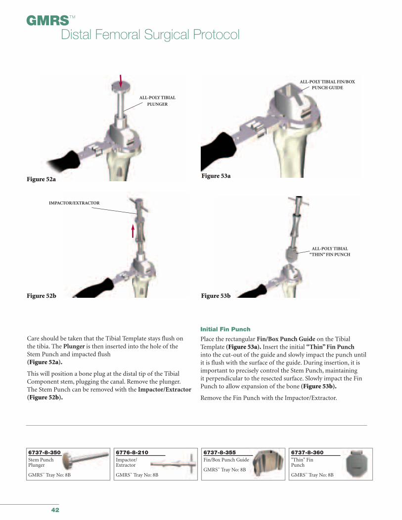
Care should be taken that the Tibial Template stays flush onthe tibia. The Plunger is then inserted into the hole of theStem Punch and impacted flush(Figure 52a).
This will position a bone plug at the distal tip of the TibialComponent stem, plugging the canal. Remove the plunger.The Stem Punch can be removed with the Impactor/Extractor(Figure 52b).
Initial Fin Punch
Place the rectangular Fin/Box Punch Guide on the TibialTemplate (Figure 53a). Insert the initial “Thin” Fin Punchinto the cut-out of the guide and slowly impact the punch untilit is flush with the surface of the guide. During insertion, it isimportant to precisely control the Stem Punch, maintaining it perpendicular to the resected surface. Slowly impact the FinPunch to allow expansion of the bone (Figure 53b).
Remove the Fin Punch with the Impactor/Extractor.
Figure 52a
Figure 52b
ALL-POLY TIBIAL
PLUNGER
IMPACTOR/EXTRACTOR
Figure 53a
Figure 53b
ALL-POLY TIBIAL FIN/BOXPUNCH GUIDE
ALL-POLY TIBIAL “THIN” FIN PUNCH
6776-8-210Impactor/Extractor
GMRS™ Tray No: 8B
6737-8-355Fin/Box Punch Guide
GMRS™ Tray No: 8B
6737-8-360"Thin" FinPunch
GMRS™ Tray No: 8B
6737-8-350Stem PunchPlunger
GMRS™ Tray No: 8B
43
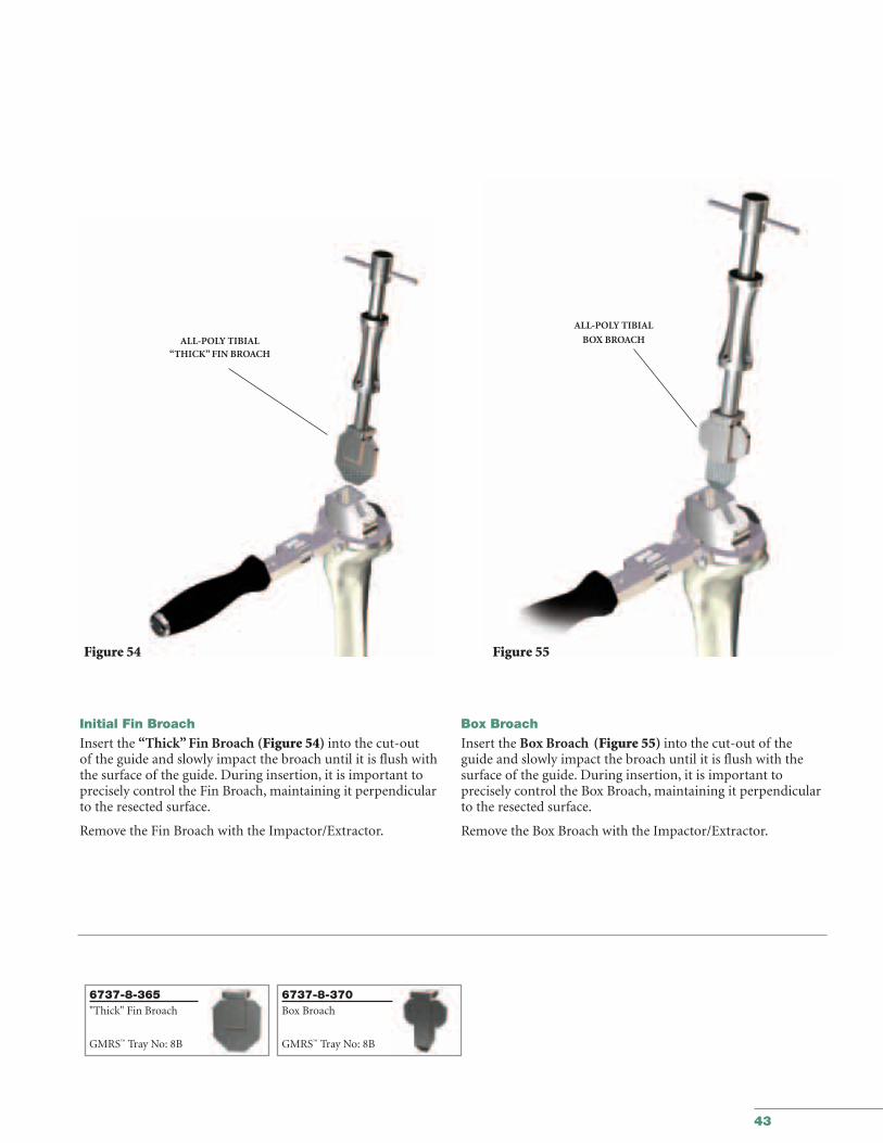
Initial Fin Broach
Insert the “Thick” Fin Broach (Figure 54) into the cut-out of the guide and slowly impact the broach until it is flush withthe surface of the guide. During insertion, it is important toprecisely control the Fin Broach, maintaining it perpendicularto the resected surface.
Remove the Fin Broach with the Impactor/Extractor.
Box Broach
Insert the Box Broach (Figure 55) into the cut-out of theguide and slowly impact the broach until it is flush with thesurface of the guide. During insertion, it is important to precisely control the Box Broach, maintaining it perpendicularto the resected surface.
Remove the Box Broach with the Impactor/Extractor.
ALL-POLY TIBIAL “THICK” FIN BROACH
Figure 54 Figure 55
ALL-POLY TIBIAL
BOX BROACH
6737-8-365"Thick" Fin Broach
GMRS™ Tray No: 8B
6737-8-370Box Broach
GMRS™ Tray No: 8B
44
GMRS™
Distal Femoral Surgical Protocol
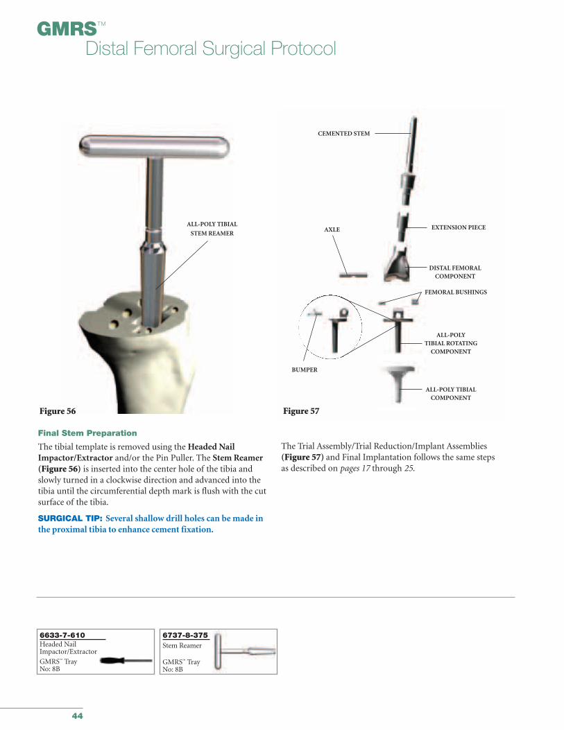
Final Stem Preparation
The tibial template is removed using the Headed NailImpactor/Extractor and/or the Pin Puller. The Stem Reamer(Figure 56) is inserted into the center hole of the tibia andslowly turned in a clockwise direction and advanced into thetibia until the circumferential depth mark is flush with the cutsurface of the tibia.
SURGICAL TIP: Several shallow drill holes can be made inthe proximal tibia to enhance cement fixation.
ALL-POLY TIBIAL
STEM REAMER
Figure 56
The Trial Assembly/Trial Reduction/Implant Assemblies(Figure 57) and Final Implantation follows the same steps as described on pages 17 through 25.
CEMENTED STEM
EXTENSION PIECE
DISTAL FEMORAL COMPONENT
FEMORAL BUSHINGS
AXLE
BUMPER
Figure 57
ALL-POLY TIBIALCOMPONENT
ALL-POLYTIBIAL ROTATING
COMPONENT
6633-7-610Headed NailImpactor/Extractor
GMRS™ TrayNo: 8B
6737-8-375Stem Reamer
GMRS™ TrayNo: 8B

APPENDIX IIITaper Disassembly
45
46
GMRS™
Distal Femoral Surgical Protocol
Figure 58a
CHISEL
NUT
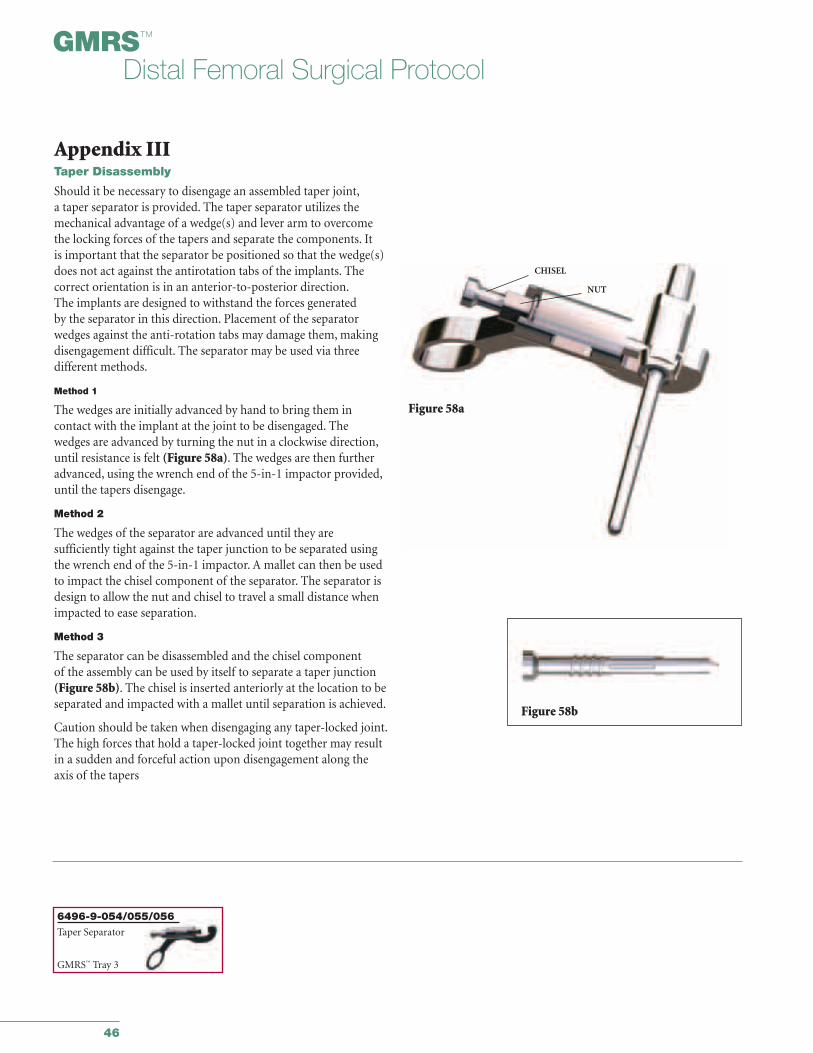
Appendix IIITaper Disassembly
Should it be necessary to disengage an assembled taper joint,a taper separator is provided. The taper separator utilizes themechanical advantage of a wedge(s) and lever arm to overcomethe locking forces of the tapers and separate the components. It is important that the separator be positioned so that the wedge(s)does not act against the antirotation tabs of the implants. The correct orientation is in an anterior-to-posterior direction.The implants are designed to withstand the forces generated by the separator in this direction. Placement of the separatorwedges against the anti-rotation tabs may damage them, makingdisengagement difficult. The separator may be used via three different methods.
Method 1
The wedges are initially advanced by hand to bring them in contact with the implant at the joint to be disengaged. The wedges are advanced by turning the nut in a clockwise direction,until resistance is felt (Figure 58a). The wedges are then furtheradvanced, using the wrench end of the 5-in-1 impactor provided,until the tapers disengage.
Method 2
The wedges of the separator are advanced until they are sufficiently tight against the taper junction to be separated usingthe wrench end of the 5-in-1 impactor. A mallet can then be usedto impact the chisel component of the separator. The separator isdesign to allow the nut and chisel to travel a small distance whenimpacted to ease separation.
Method 3
The separator can be disassembled and the chisel component of the assembly can be used by itself to separate a taper junction(Figure 58b). The chisel is inserted anteriorly at the location to beseparated and impacted with a mallet until separation is achieved.
Caution should be taken when disengaging any taper-locked joint.The high forces that hold a taper-locked joint together may resultin a sudden and forceful action upon disengagement along theaxis of the tapers
Figure 58b
6496-9-054/055/056Taper Separator
GMRS™ Tray 3
47
IMPLANT LISTING
and
RESECTION LENGTHOVERVIEW CHART

48
GMRS™
Distal Femoral Surgical Protocol
Description Size Cat. No. Left Cat. No. RightDistal Femoral Component Small 6495-2-010 6495-2-020Distal Femoral Component Standard 6495-2-030 6495-2-040
Description Size Cat. No. Description Size Cat. No.Extension Piece 30mm 6495-6-030 Extension Piece 120mm 6495-6-120Extension Piece 40mm 6495-6-040 Extension Piece 140mm 6495-6-140Extension Piece 50mm 6495-6-050 Extension Piece 160mm 6495-6-160Extension Piece 60mm 6495-6-060 Extension Piece 180mm 6495-6-180Extension Piece 70mm 6495-6-070 Extension Piece 200mm 6495-6-200Extension Piece 80mm 6495-6-080 Extension Piece 220mm 6495-6-220Extension Piece 100mm 6495-6-100
Straight Stem Curved Stem Long Curved StemDescription Size With porous W/O porous With porous W/O porous With porous W/O porous
coated body coated body coated body coated body coated body coated bodysection section section section section section
Cemented Stem 8mm 6485-3-008 6485-3-018 6485-3-308 6485-3-318 - -Cemented Stem 9mm 6485-3-009 6485-3-019 6485-3-309 6485-3-319 - -Cemented Stem 10mm 6485-3-000 6485-3-010 6485-3-300 6485-3-310 - -Cemented Stem 11mm 6485-3-011 6485-3-111 6485-3-711 6485-3-811 6485-3-311 6485-3-611Cemented Stem 13mm 6485-3-013 6485-3-113 6485-3-713 6485-3-813 6485-3-313 6485-3-613Cemented Stem 15mm 6485-3-015 6485-3-115 6485-3-715 6485-3-815 6485-3-315 6485-3-615Cemented Stem 17mm 6485-3-017 6485-3-117 6485-3-717 6485-3-817 6485-3-317 6485-3-617
Description Size Cat. No.MRH Axle Standard 6481-2-120GMRS™ Axle for Small Distal Femur Small 6495-2-115
MRH Femoral Bushing Standard 6481-2-110GMRS™ Bushing for Small Distal Femur Small 6495-2-105
Tibial Sleeve All Sizes 6481-2-140Bumper Insert Neutral 6481-2-130Bumper Insert 3 Degrees 6481-2-133
Description Size Cat. No.MRH Tibial Rotating Component All Sizes 6481-2-100
Description Thickness Cat. No. S1/S2 Cat. No. M2/L2MRH Tibial Insert 10mm 6481-3-210 6481-3-310MRH Tibial Insert 13mm 6481-3-213 6481-3-313MRH Tibial Insert 16mm 6481-3-216 6481-3-316MRH Tibial Insert 20mm 6481-3-220 6481-3-320MRH Tibial Insert 24mm 6481-3-224 6481-3-324
Description Size Cat. No.MRH Keel Tibial Baseplate S1 6481-3-110MRH Keel Tibial Baseplate S2 6481-3-111MRH Keel Tibial Baseplate M2 6481-3-112MRH Keel Tibial Baseplate L2 6481-3-113
Description Size Fluted (Titanium) Press-fit (Cobalt Chrome)80mm 155mm 80mm 155mm
Stem Extender 10mm 6478-6-600 6478-6-680 6478-6-395 6478-6-435Stem Extender 11mm 6478-6-605 6478-6-685 6478-6-396 6478-6-436Stem Extender 12mm 6478-6-610 6478-6-690 6478-6-397 6478-6-437Stem Extender 13mm 6478-6-615 6478-6-695 6478-6-398 6478-6-438Stem Extender 14mm 6478-6-620 6478-6-705 6478-6-399 6478-6-439Stem Extender 15mm 6478-6-625 6478-6-710 6478-6-400 6478-6-440Stem Extender 16mm 6478-6-630 6478-6-715 6478-6-405 6478-6-445Stem Extender 17mm 6478-6-635 6478-6-720 6478-6-410 6478-6-450Stem Extender 18mm 6478-6-640 6478-6-725 6478-6-415 6478-6-455Stem Extender 19mm 6478-6-645 6478-6-730 6478-6-420 6478-6-460Stem Extender 21mm 6478-6-655 6478-6-740 6478-6-425 6478-6-465Stem Extender 23mm 6478-6-665 6478-6-750 6478-6-430 6478-6-470
Implant Listing
49
Description Size Left Cat. No. Right Cat. No. Description Size Cat. No.Hemi Flat Wedge 5mm Small 1 6630-6-125 6630-6-105 Full Flat Block 10mm Small 1 6630-6-510Hemi Flat Wedge 5mm Small 2 6630-6-170 6630-6-150 Full Flat Block 10mm Small 2 6630-6-515Hemi Flat Wedge 5mm Medium 2 6630-6-270 6630-6-250 Full Flat Block 10mm Medium 2 6630-6-525Hemi Flat Wedge 5mm Large 2 6630-6-370 6630-6-350 Full Flat Block 10mm Large 2 6630-6-535
Hemi Flat Wedge 10mm Small 1 6630-6-130 6630-6-110Hemi Flat Wedge 10mm Small 2 6630-6-175 6630-6-155Hemi Flat Wedge 10mm Medium 2 6630-6-275 6630-6-255Hemi Flat Wedge 10mm Large 2 6630-6-375 6630-6-355
Description Cat. No.All Poly Tibial Rotating Component 6481-2-103
Description Size X-SML Cat. No. SMALL Cat. No. MEDIUM Cat. No. LARGE Cat. No. X-LG Cat. No.KRH All Poly Tibia 8mm 6485-2-008 6485-2-108 6485-2-208 6485-2-308 6485-2-408KRH All Poly Tibia 11mm 6485-2-011 6485-2-111 6485-2-211 6485-2-311 6485-2-411KRH All Poly Tibia 16mm 6485-2-016 6485-2-116 6485-2-216 6485-2-316 6485-2-416KRH All Poly Tibia 21mm 6485-2-021 6485-2-121 6485-2-221 6485-2-321 6485-2-421
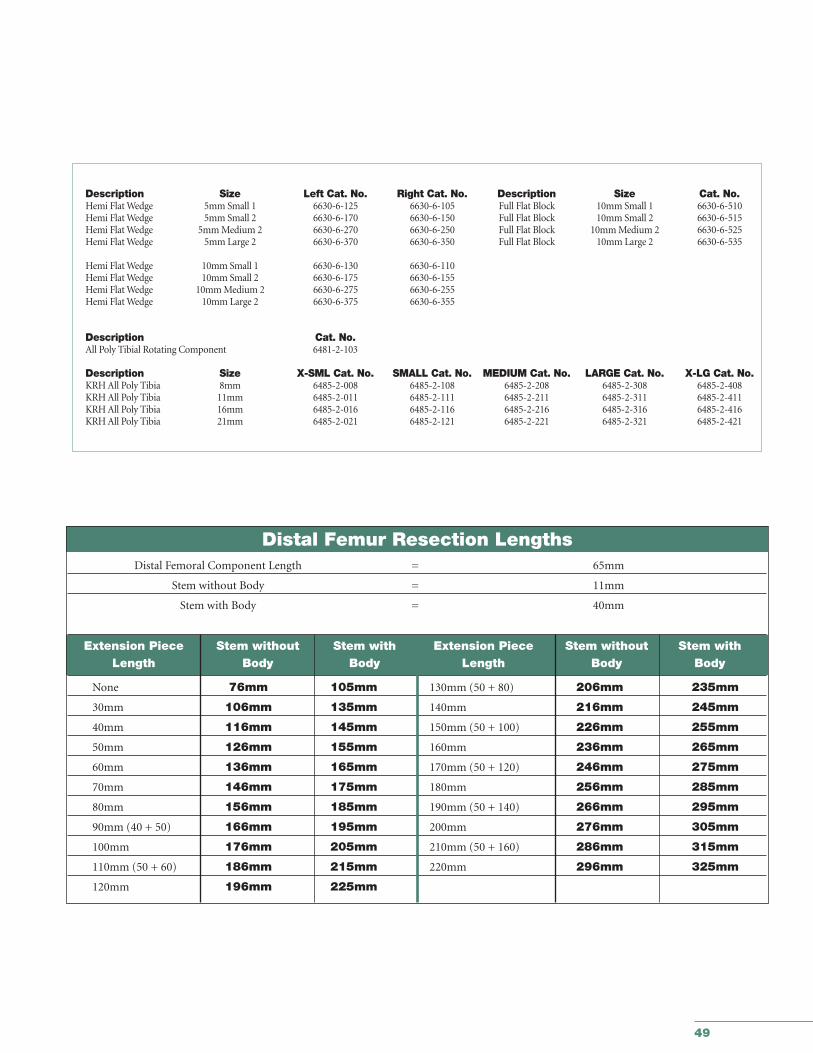
Distal Femur Resection LengthsDistal Femoral Component Length = 65mm
Stem without Body = 11mm
Stem with Body = 40mm
Extension Piece Stem without Stem with Extension Piece Stem without Stem withLength Body Body Length Body Body
None 76mm 105mm 130mm (50 + 80) 206mm 235mm
30mm 106mm 135mm 140mm 216mm 245mm
40mm 116mm 145mm 150mm (50 + 100) 226mm 255mm
50mm 126mm 155mm 160mm 236mm 265mm
60mm 136mm 165mm 170mm (50 + 120) 246mm 275mm
70mm 146mm 175mm 180mm 256mm 285mm
80mm 156mm 185mm 190mm (50 + 140) 266mm 295mm
90mm (40 + 50) 166mm 195mm 200mm 276mm 305mm
100mm 176mm 205mm 210mm (50 + 160) 286mm 315mm
110mm (50 + 60) 186mm 215mm 220mm 296mm 325mm
120mm 196mm 225mm

Joint Replacements
Trauma
Spine
Micro Implants
Orthobiologics
Instruments
Interventional Pain
Navigation
Endoscopy
Communications
Patient Handling Equipment
EMS Equipment
The information presented in this material is intended to demonstrate the breadth of Stryker product offerings. Always refer tothe package insert, product label and/or user instructions before using any Stryker product. Products may not be available inall markets. Product availability is subject to the regulatory or medical practices that govern individual markets. Please contactyour Stryker representative if you have questions about the availability of Stryker products in your area.
Products referenced with ™ designation are trademarks of Stryker.Products referenced with ® designation are registered trademarks of Stryker.
Literature Number: LSPK38GC/GS 1.5m 06/04
Copyright © Stryker 2004Printed in USA.
325 Corporate DriveMahwah, NJ 07430t: 201 831 5000
www.stryker.com