orthographic views & sectioning - city university …ra600/me1105/lectures/me1110-04.pdfahmed...
TRANSCRIPT

Ahmed Kovacevic, City University London
Design web
1
Orthographic Views & Sectioning
Prof Ahmed Kovacevic
Engineering Drawing and Design - Lecture 4
School of Engineering and Mathematical Sciences
Room C130, Phone: 8780, E-Mail: [email protected]
www.staff.city.ac.uk/~ra600/intro.htm
ME 1110 – Engineering Practice 1

Ahmed Kovacevic, City University London
Design web
2
Objectives for today
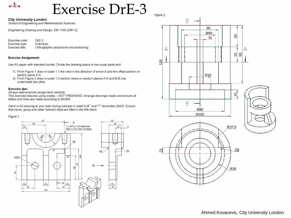
Prepare for DrE-3
Additional features in multiview drawings:
» Cutting plane, Section, hatching, hidden feature
Section views and Section drawings
» Ribs, webs, assemblies, threads

Ahmed Kovacevic, City University London
Design web
3
Orthographic Projections
Definition: Orthographic projections are
parallel projections that
Preserve true relationship between
features
Parallel lines are drawn parallel
The geometry is generally not distorted
Parallel projectors
Light from a point source at an infinite distance
View from a distance through a telescope

Ahmed Kovacevic, City University London
Design web
4
Orthographic Projection Properties
Projection planesHorizontal, frontal, and profile
Each projection plane is perpendicular to adjacent projection planes
Views top, front, and right side
Only use the views that are needed to represent the object
The most descriptive view should be the front view
Represented with dashed lines
Views should be selected to minimize the use of hidden lines

Ahmed Kovacevic, City University London
Design web
5
Angle projections
Third Angle Projection Associated with English units
If English units are used assume third angle projection unless otherwise specified
Include ANSI standard symbol
First Angle Projection
Associated with SI units (International System of units)
Ahmed Kovacevic, City University London
Design web
6
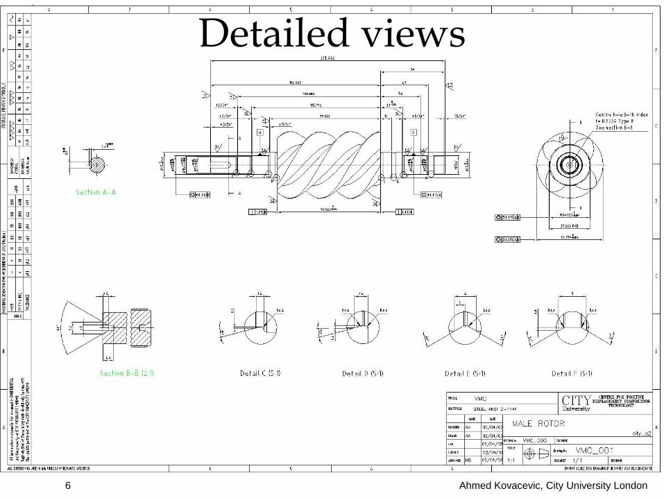
Detailed views
Ahmed Kovacevic, City University London
Design web
7
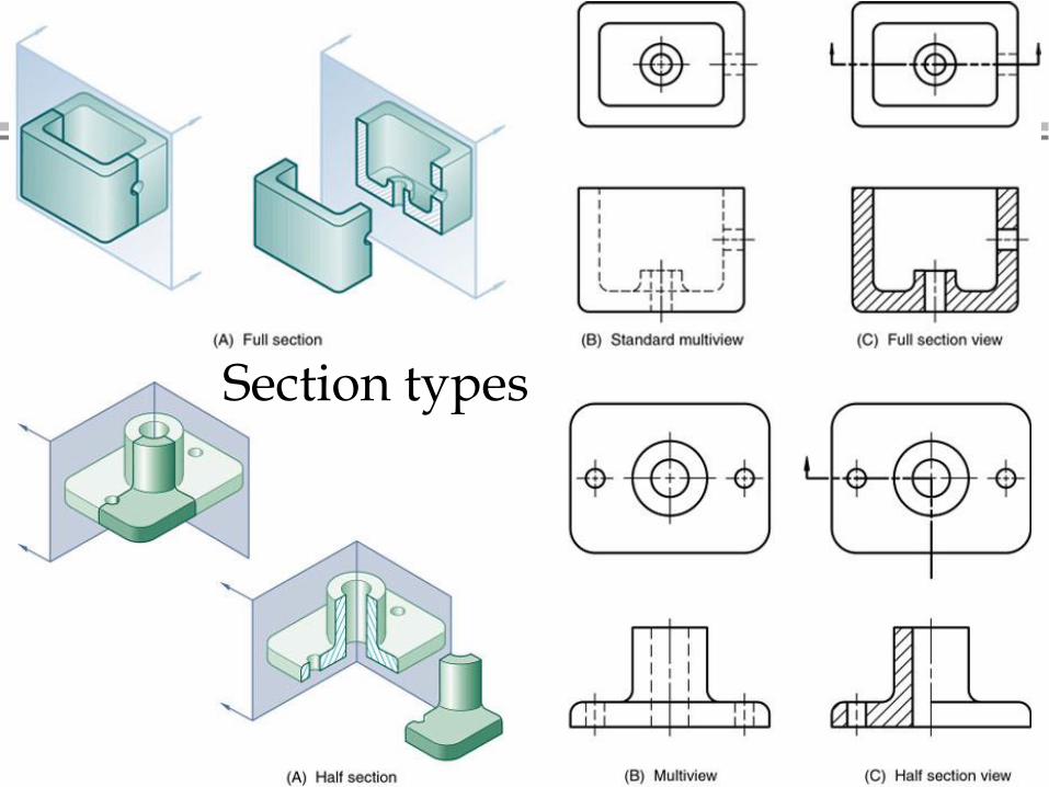
Sectioned Drawing
Definition: » A multiview technical drawing that reveals details
about internal features by displaying the part as if cut by an imaginary cutting plane
Objective: » To make the drawing more understandable,
especially the internal details of the part
Principles:» Since the sectioned drawing shows internal
features there is generally no need to show hidden lines
» Helpful for both, detailed and assembly drawings

Ahmed Kovacevic, City University London
Design web
8
How to reveal hidden feature
Ahmed Kovacevic, City University London
Design web
9
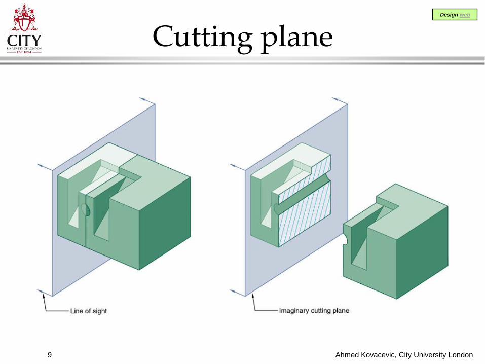
Cutting plane

Ahmed Kovacevic, City University London
Design web
10
Hidden lines

Ahmed Kovacevic, City University London
Design web
11
Surfaces and edges in section views

Ahmed Kovacevic, City University London
Design web
12
Positioning
Hatching of thin parts
Ahmed Kovacevic, City University London
Design web
13
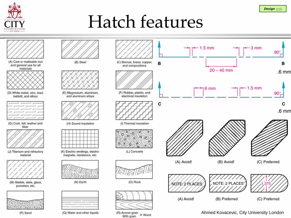
Hatch features
Ahmed Kovacevic, City University London
Design web
14
Section types
Ahmed Kovacevic, City University London
Design web
15
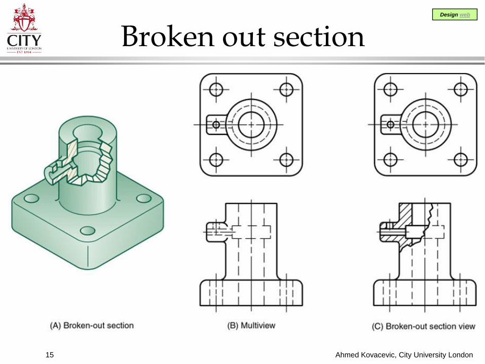
Broken out section

Ahmed Kovacevic, City University London
Design web
16
Revolved & Removed
Ahmed Kovacevic, City University London
Design web
17
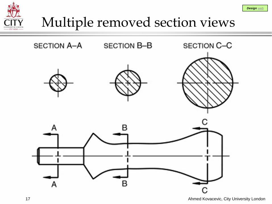
Multiple removed section views

Ahmed Kovacevic, City University London
Design web
18
Offset section

Ahmed Kovacevic, City University London
Design web
19
Assembly section

Ahmed Kovacevic, City University London
Design web
20
Convention for webs

Ahmed Kovacevic, City University London
Design web
21
Alternate methods for webs

Ahmed Kovacevic, City University London
Design web
22
Aligned
Aligned sectionsAligned spokes
Aligned ribs
Aligned lugs

Ahmed Kovacevic, City University London
Design web
23
Threads

Ahmed Kovacevic, City University London
Design web
24
Break symbols
Ahmed Kovacevic, City University London
Design web
25
Exercise DrE-3