orissa state road project - osrp culvert design report... · orissa state road project final...
TRANSCRIPT

GOVERNMENT OF ORISSA
WORKS DEPARTMENT
ORISSA STATE ROAD PROJECT
FINAL DETAILED ENGINEERING REPORT
FOR PHASE-I ROADS DESIGN REPORT OF CULVERTS
(BERHAMPUR TO BANGI JUNCTION) (0.0 TO 41.0)
C O N S U L T I N GC O N S U L T I N GC O N S U L T I N GC O N S U L T I N G
Engineers Group Ltd. Jaipur E-12, Moji Colony, Malviya Nagar , Jaipur, Raj. �+ 91-141-2520899, Telefax +91-141-2521348 E-mail : [email protected] URL : www.cegindia.com
Consulting Engineers Group Ltd., Jaipur Culvert Design Report
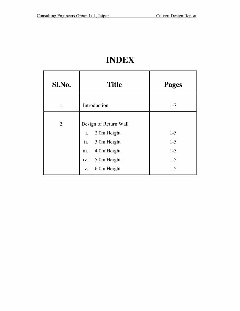
INDEX
Sl.No.
Title
Pages
1.
Introduction
1-7
2.
Design of Return Wall
i. 2.0m Height
ii. 3.0m Height
iii. 4.0m Height
iv. 5.0m Height
v. 6.0m Height
1-5
1-5
1-5
1-5
1-5

CEG.Ltd., Jaipur Culvert Design Report
Consultancy Services for Feasibility Study and Detailed
Project Preparation for Proposed Orissa State Road Project
INTRODUCTION

Consulting Engineers Group Ltd., Jaipur Culvert Design Report
INTRODUCTION
The culverts have been categorized on the basis of detailed inventory and condition
survey, hydrological study, horizontal & vertical profile of highway.
The following criterion has been taken while deciding the culverts :
i. The width of culvert shall be 12.0m
ii. NP-3/NP-4 pipe culverts in good condition and hydrologically adequate shall be
retained
iii. Slab culverts structurally in good condition and hydrologically adequate having width
less than 10.0m shall be widened as per approved alignment.
iv. All arch type culverts shall be reconstructed.
v. All new pipe culverts shall have minimum dia. of 1.0m and box culverts of minimum
span 2.0m and height 1.5m.
vi. RR stone masonry culverts shall be reconstructed.
vii. Additional culverts as per site investigation has been identified and included in this
report.
On the basis of above, all culverts lies in the following category :
i. Single Pipe Culverts of 1.0m dia
ii. Double Pipe Culverts of 1.0m dia
iii. Extension of Pipe Culverts with existing pipe dia
iv. Single Cell box Culverts upto span of 6.0m
v. Widening of Slab Culverts
On the basis of above, all culverts in this stretch lies the following category
Summary of Proposed Culverts
Type of Culvert Nos.
Culverts Retained Nil
Culverts Widened
Pipe extension 5
Slab widening 12
Culverts Replaced
New Single Pipe 51
New Double Pipe 9
New Single Box of 1/22/0 21
New Single Box of 1/22/1 1
New Single Box of 1/23/0 22
New Single Box of 1/33/0 12
New Single Box of 1/34/0 1
New Single Box of 1/43/0 2
New Single Box of 1/44/0 1
Total 137

Consulting Engineers Group Ltd., Jaipur Culvert Design Report
The drawings of Pipe Culverts for height of fill from 0.6 to 4.0m has been taken from
SP-13.For Box Culverts with different clear heights MOST Standard Drawings has been
taken.
Bed levels, Formation levels, Super-elevation/Camber has been taken from highway
plan & profile drawings and data has been analysed by using Microsoft Excel Sheet.
In Box Culverts, the retaining wall is kept along the road instead of splayed Wing
Wall mentioned in MOST Drawings. These Walls has been designed by using Microsoft
Excel Sheet for the height varying from 2.0 to 6.0m.
Reference codes:
IRC – 6 – 2000
IRC – 21 – 2000
IRC – 78 – 2000
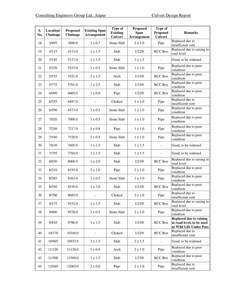
Proposed Culverts
S.
No.
Location/
Chainage
Proposed
Chainage
Existing Span
Arrangement
Type of
Existing
Culvert
Proposed
Span
Arrangement
Type of
Proposed
Culvert
Remarks
1 0/190 213.0 - Choked 2 x 1.0 Pipe Replaced due to
insufficient vent
2 0/350 369.0 1 x 1.75 Slab 1 x 1.75 - Good, to be widened
3 0/830 847.0 1 x 2.0 Slab 1 x 2.0 - Good, to be widened
4 0/950 975.0 - Choked 2 x 1.0 Pipe Replaced due to
insufficient vent
5 1/150 1146.0 1 x 1.5 Slab 1/23/0 RCC Box Replaced due to poor
condition
6 1/310 1310.0 1 x 1.5 Slab 1/22/0 RCC Box Replaced due to raising in
road level
7 1/785 1781.0 1 x 1.5 Slab 1/23/0 RCC Box Replaced due to poor
condition
8 2/140 2137.0 1 x 1.5 Slab 1/23/0 RCC Box Replaced due to poor
condition, to be used as
Wild Life Under Pass
9 2/285 2332.0 1 x 1.5 Slab 1/22/0 RCC Box Replaced due to
insufficient vent
10 2/515 2515.0 3 x 0.9 Slab 1/43/0 RCC Box Replaced due to poor
condition
11 2/630 2629.0 1 x 1.5 Slab 1 x 1.5 - Good, to be widened
12 2/745 2742.0 1 x 2.5 Slab 1/33/0 RCC Box Replaced due to raising in
road level
13 3/105 3095.0 1 x 0.5 Stone Slab 1 x 1.0 Pipe Replaced due to
insufficient vent
14 3/265 3259.0 1 x 0.8 Pipe 1 x 1.0 Pipe Replaced due to
insufficient vent
15 3/390 3382.0 1 x 1.4 Slab 1/23/0 RCC Box Replaced due to poor
condition
16 3/505 3498.0 1 x 2.5 Slab 1/33/0 RCC Box Replaced due to raising in
road level
17 3/775 3765.0 1 x 0.7 Stone Slab 1 x 1.0 Pipe Replaced due to poor
condition
Consulting Engineers Group Ltd., Jaipur Culvert Design Report
S.
No.
Location/
Chainage
Proposed
Chainage
Existing Span
Arrangement
Type of
Existing
Culvert
Proposed
Span
Arrangement
Type of
Proposed
Culvert
Remarks
18 3/895 3890.0 1 x 0.7 Stone Slab 2 x 1.0 Pipe Replaced due to
insufficient vent
19 4/115 4115.0 1 x 1.5 Slab 1/22/0 RCC Box Replaced due to raising in
road level
20 5/145 5127.0 1 x 1.5 Slab 1 x 1.5 - Good, to be widened
21 5/230 5215.0 1 x 0.5 Stone Slab 1 x 1.0 Pipe Replaced due to poor
condition
22 5/535 5521.0 2 x 1.5 Arch 1/33/0 RCC Box Replaced due to poor
condition
23 5/775 5761.0 1 x 2.5 Slab 1/33/0 RCC Box Replaced due to poor
condition
24 6/090 6069.0 1 x 0.8 Pipe 1/22/0 RCC Box Replaced due to poor
condition
25 6/555 6497.0 - Choked 1 x 1.0 Pipe Replaced due to
insufficient vent
26 6/590 6573.0 1 x 0.5 Stone Slab 1 x 1.0 Pipe Replaced due to poor
condition
27 7/020 7000.0 1 x 0.5 Stone Slab 1 x 1.0 Pipe Replaced due to poor
condition
28 7/240 7217.0 1 x 0.8 Pipe 1 x 1.0 Pipe Replaced due to poor
condition
29 7/540 7520.0 1 x 0.5 Stone Slab 1 x 1.0 Pipe Replaced due to poor
condition
30 7/630 7605.0 1 x 1.5 Slab 1 x 1.5 - Good, to be widened
31 7/795 7769.0 1 x 1.5 Slab 1 x 1.5 - Good, to be widened
32 8/030 8008.0 1 x 2.0 Slab 1/23/0 RCC Box Replaced due to raising in
road level
33 8/210 8193.0 2 x 1.0 Pipe 2 x 1.0 Pipe Replaced due to poor
condition
34 8/385 8363.0 1 x 0.5 Stone Slab 1 x 1.0 Pipe Replaced due to poor
condition
35 8/550 8530.0 1 x 3.0 Slab 1/33/0 RCC Box Replaced due to poor
condition
36 8/700 8685.0 - Choked 2 x 1.0 Pipe Replaced due to
insufficient vent
37 9/175 9152.0 1 x 1.5 Slab 1/23/0 RCC Box Replaced due to raising in
road level
38 9/600 9538.0 1 x 0.5 Stone Slab 2 x 1.0 Pipe Replaced due to poor
condition
39 9/810 9786.0 1 x 1.5 Slab 1/23/0 RCC Box Replaced due to raising
in road level, to be used
as Wild Life Under Pass
40 10/370 10340.0 - Choked 1/22/0 RCC Box Replaced due to
insufficient vent
41 10/965 10933.0 2 x 1.5 Slab 2 x 1.5 - Good, to be widened
42 11/120 11120.0 1 x 0.9 Arch 2 x 1.0 Pipe Replaced due to poor
condition
43 11/500 11500.0 1 x 1.5 Slab 1/23/0 RCC Box Replaced due to poor
condition
44 12/040 12065.0 2 x 0.8 Pipe 2 x 1.0 Pipe Replaced due to
insufficient vent

Consulting Engineers Group Ltd., Jaipur Culvert Design Report
S.
No.
Location/
Chainage
Proposed
Chainage
Existing Span
Arrangement
Type of
Existing
Culvert
Proposed
Span
Arrangement
Type of
Proposed
Culvert
Remarks
45 12/380 12407.0 1 x 1.0 Pipe 1 x 1.0 Pipe Replaced due to poor
condition
46 12/585 12611.0 1 x 0.8 Pipe 1 x 1.0 Pipe Replaced due to poor
condition
47 12/810 12836.0 3 x 1.2 Pipe 1/33/0 RCC Box Replaced due to poor
condition
48 12/880 12907.0 1 x 0.9 Pipe 1 x 0.9 - Good, to be extended
49 13/110 13132.0 1 x 0.5 Stone Slab 1 x 1.0 Pipe Replaced due to poor
condition
50 13/265 13288.0 1 x 1.5 Slab 1/23/0 RCC Box Replaced due to poor
condition
51 13/450 13470.0 1 x 3.0 Slab 1/33/0 RCC Box Replaced due to raising in
road level
52 13/600 13619.0 1 x 0.8 Pipe 1 x 1.0 Pipe Replaced due to poor
condition
53 13/790 13809.0 1 x 1.2 Pipe 1/22/0 RCC Box Replaced due to poor
condition
54 13/895 13916.0 1 x 1.0 Pipe 1 x 1.0 - Good, to be extended
55 14/135 14157.0 1 x 3.0 Slab 1 x 3.0 - Good, to be widened
56 14/510 14531.0 1 x 0.6 Pipe 1 x 1.0 Pipe Replaced due to
insufficient vent
57 14/855 14877.0 1 x 1.5 Slab 1/22/0 RCC Box Replaced due to poor
condition
58 15/430 15440.0 1 x 0.6 Pipe 1 x 1.0 Pipe Replaced due to
insufficient vent
59 15/880 15897.0 NV Pipe 1 x 1.0 Pipe Replaced due to
insufficient vent
60 16/050 16068.0 1 x 0.8 Pipe 1 x 1.0 Pipe Replaced due to
insufficient vent
61 16/400 16417.0 1 x 2.3 Slab 1/33/0 RCC Box Replaced due to poor
condition
62 16/505 16521.0 1 x 0.8 Pipe 1 x 1.0 Pipe Replaced due to poor
condition
63 16/750 16770.0 NV Pipe 1 x 1.0 Pipe Replaced due to
insufficient vent
64 16/950 16970.0 1 x 0.6 Pipe 1 x 1.0 Pipe Replaced due to
submergence
65 17/650 17666.0 1 x 0.9 Pipe 1 x 1.0 Pipe Replaced due to poor
condition
66 18/020 18028.0 2 x 1.7 Slab 1/43/0 RCC Box Replaced due to raising in
road level
67 18/105 18115.0 1 x 1.0 Slab 1/22/0 RCC Box Replaced due to poor
condition
68 18/470 18480.0 1 x 0.6 Stone Slab 1 x 1.0 Pipe Replaced due to poor
condition
69 19/240 19192.0 1 x 0.9 Slab 2 x 1.0 Pipe Replaced due to poor
condition
70 19/430 19382.0 1 x 0.6 Slab 1 x 1.0 Pipe Replaced due to poor
condition
71 19/570 19530.0 1 x 1.5 Slab 1/22/0 RCC Box Replaced due to raising in
road level
72 19/845 19799.0 1 x 1.0 Pipe 1 x 1.0 - Good, to be extended
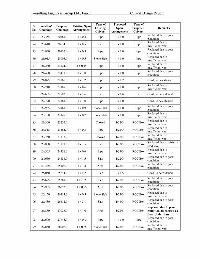
Consulting Engineers Group Ltd., Jaipur Culvert Design Report
S.
No.
Location/
Chainage
Proposed
Chainage
Existing Span
Arrangement
Type of
Existing
Culvert
Proposed
Span
Arrangement
Type of
Proposed
Culvert
Remarks
73 20/355 20361.0 1 x 0.8 Pipe 1 x 1.0 Pipe Replaced due to poor
condition
74 20/610 20614.0 1 x 0.5 Slab 1 x 1.0 Pipe Replaced due to
insufficient vent
75 20/930 20935.0 1 x 0.8 Pipe 1 x 1.0 Pipe Replaced due to poor
condition
76 21/015 21005.0 1 x 0.5 Stone Slab 1 x 1.0 Pipe Replaced due to
insufficient vent
77 21/230 21224.0 1 x 0.45 Pipe 1 x 1.0 Pipe Replaced due to
insufficient vent
78 21/420 21411.0 1 x 1.0 Pipe 1 x 1.0 Pipe Replaced due to poor
condition
79 21/875 21865.0 1 x 1.2 Pipe 1 x 1.2 - Good, to be extended
80 22/210 22189.0 1 x 0.6 Pipe 1 x 1.0 Pipe Replaced due to
insufficient vent
81 22/605 22582.0 1 x 1.6 Slab 1 x 1.6 - Good, to be widened
82 22/790 22761.0 1 x 1.0 Pipe 1 x 1.0 - Good, to be extended
83 22/985 22961.0 1 x 0.9 Stone Slab 1 x 1.0 Pipe Replaced due to poor
condition
84 23/180 23147.0 1 x 0.7 Stone Slab 1 x 1.0 Pipe Replaced due to
insufficient vent
85 23/300 23255.0 Choked 1/22/0 RCC Box Replaced due to
insufficient vent
86 23/515 23484.0 1 x 0.3 Pipe 1/22/0 RCC Box Replaced due to
insufficient vent
87 23/750 23713.0 Choked 1/22/0 RCC Box Replaced due to
insufficient vent
88 23/850 23821.0 1 x 1.5 Slab 1/23/0 RCC Box Replaced due to raising in
road level
89 24/365 24351.0 1 x 0.6 Pipe 1/34/0 RCC Box Replaced due to
insufficient vent
90 24/650 24636.0 1 x 1.5 Slab 1/22/0 RCC Box Replaced due to poor
condition
91 24/1020 25106.0 1 x 1.8 Arch 1/23/0 RCC Box Replaced due to poor
condition
92 25/050 25214.0 1 x 4.7 Slab 1 x 1.5 - Good, to be widened
93 25/695 25861.0 1 x 1.85 Slab 1/22/0 RCC Box Replaced due to poor
condition
94 25/905 26072.0 1 x 0.95 Arch 1/22/0 RCC Box Replaced due to poor
condition
95 26/150 26314.0 1 x 0.5 Stone Slab 1/23/0 RCC Box Replaced due to
insufficient vent
96 26/430 26612.0 1 x 3.1 Slab 1/44/0 RCC Box Replaced due to poor
condition
97 26/850 27026.0 1 x 1.0 Arch 1/22/1 RCC Box Replaced due to poor
condition, to be used as
Bear Under Pass
98 27/600 27743.0 1 x 0.8 Pipe 1 x 1.0 Pipe Replaced due to poor
condition
99 27/850 28008.0 1 x 0.65 Stone Slab 1/23/0 RCC Box Replaced due to
insufficient vent

Consulting Engineers Group Ltd., Jaipur Culvert Design Report
S.
No.
Location/
Chainage
Proposed
Chainage
Existing Span
Arrangement
Type of
Existing
Culvert
Proposed
Span
Arrangement
Type of
Proposed
Culvert
Remarks
100 28/375 28547.0 Choked 1 x 1.0 Pipe Replaced due to
insufficient vent
101 28/800 28954.0 3 x 1.2 Pipe 1/33/0 RCC Box Replaced due to poor
condition
102 30/060 30241.0 1 x 3.0 Slab 1/33/0 RCC Box Replaced due to raising in
road level
103 30/460 30637.0 1 x 0.8 Pipe 1 x 1.0 Pipe Replaced due to poor
condition
104 30/720 30889.0 1 x 1.8 Slab 1/23/0 RCC Box Replaced due to raising in
road level
105 31/960 32128.0 1 x 0.8 Stone Slab 1/22/0 RCC Box Replaced due to poor
condition
106 32/300 32465.0 NV Pipe 1 x 1.0 Pipe Replaced due to
insufficient vent
107 33/220 33402.0 1 x 1.5 Slab 1/22/0 RCC Box Replaced due to poor
condition
108 33/310 33476.0 1 x 1.6 Slab 1/22/0 RCC Box Replaced due to poor
condition
109 33/806 33976.0 NV Pipe 1 x 1.0 Pipe Replaced due to
insufficient vent
110 33/900 34069.0 1 x 0.8 Pipe 1 x 1.0 Pipe Replaced due to
insufficient vent
111 34/250 34463.0 1 x 0.8 Pipe 1 x 1.0 Pipe Replaced due to
insufficient vent
112 34/525 34670.0 1 x 2.9 Slab 1/33/0 RCC Box Replaced due to poor
condition
113 34/640 34813.0 2 x 0.9 Pipe 1/23/0 RCC Box Replaced due to
insufficient vent
114 34/675 34858.0 1 x 2.1 Arch 1/33/0 RCC Box Replaced due to poor
condition
115 35/204 35378.0 1 x 0.5 Stone Slab 1 x 1.0 Pipe Replaced due to
insufficient vent
116 35/350 35533.0 1 x 0.5 Stone Slab 1 x 1.0 Pipe Replaced due to
insufficient vent
117 35/825 36003.0 1 x 0.5 Stone Slab 1 x 1.0 Pipe Replaced due to
insufficient vent
118 36/060 36238.0 1 x 0.5 Stone Slab 1 x 1.0 Pipe Replaced due to
insufficient vent
119 36/220 36358.0 - Choked 1 x 1.0 Pipe Replaced due to
insufficient vent
120 36/500 36594.0 1 x 0.6 Pipe 1 x 1.0 Pipe Replaced due to poor
condition
121 36/575 36758.0 1 x 0.8 Pipe 1 x 1.0 Pipe Replaced due to poor
condition
122 36/800 36961.0 NV Pipe 1 x 1.0 Pipe Replaced due to
insufficient vent
123 36/990 37164.0 1 x 0.5 Stone Slab 1 x 1.0 Pipe Replaced due to
insufficient vent
124 37/440 37619.0 1 x 0.8 Arch 1/23/0 RCC Box Replaced due to poor
condition
125 37/985 38157.0 1 x 0.5 Stone Slab 1 x 1.0 Pipe Replaced due to
insufficient vent
126 38/450 38483.0 1 x 1.5 Slab 1 x 1.5 - Good, to be widened
127 38/600 38746.0 1 x 1.5 Slab 1/22/0 RCC Box Replaced due to poor
condition

Consulting Engineers Group Ltd., Jaipur Culvert Design Report
S.
No.
Location/
Chainage
Proposed
Chainage
Existing Span
Arrangement
Type of
Existing
Culvert
Proposed
Span
Arrangement
Type of
Proposed
Culvert
Remarks
128 38/810 39002.0 NV Choked 1 x 1.0 Pipe Replaced due to
insufficient vent
129 38/960 39118.0 1 x 0.8 Arch 1/23/0 RCC Box Replaced due to poor
condition
130 39/195 39375.0 1 x 1.8 Arch 1/23/0 RCC Box Replaced due to poor
condition
131 39/340 39517.0 1 x 3.2 Slab 1 x 3.2 - Good, to be widened
132 39/455 39671.0 1 x 0.8 Arch 1/23/0 RCC Box Replaced due to poor
condition
133 39/900 40090.0 1 x 0.85 Arch 1/23/0 RCC Box Replaced due to poor
condition
134 40/100 40280.0 1 x 1.35 Slab 1/22/0 RCC Box Replaced due to poor
condition
135 40/240 40437.0 2 x 0.45 Stone Slab 1/22/0 RCC Box Replaced due to
insufficient vent
136 40/420 40610.0 1 x 1.5 Slab 1/23/0 RCC Box Replaced due to poor
condition
137 40/815 41000.0 1 x 1.5 Slab 1/23/0 RCC Box Replaced due to poor
condition

CEG.Ltd., Jaipur Culvert Design Report
Consultancy Services for Feasibility Study and Detailed
Project Preparation for Proposed Orissa State Road Project
DESIGN OF RETURN WALL

Consulting Engineers Group Ltd., Jaipur
_________________________________________________________________________________
Culvert Design Report
_________________________________________________________
Top of Earth fill
Top level of wall
0.30
1.700
Earth Fill
2.000
Ground level
Heel Toe0.300 0.300 0.300
1.300 0.300 0.400
2.000
Str
aig
ht port
ion o
f ste
m =
9
13
2
3
4 6
5711 14
1
8
10
12
9
13
2
3
4 6
5711 14
1
8
10
12

Consulting Engineers Group Ltd., Jaipur
_________________________________________________________________________________
Culvert Design Report
_________________________________________________________
DESIGN OF RETAINING WALL FOR 2.000 m HEIGHT
DESIGN DATA:
Top level of retaining wall = 2.000 m
Ground level = 1.000 m
Founding Level = 0.000 m
Total Height from top of wall to founding level = 2.000 m
Density of earth = 1.8 t/m3
Density of concrete = 2.4 t/m3
Clear cover to Reinforcement = 0.05 m
Clear cover to Reinforcement for foundations = 0.075 m
Grade of concrete = 20
Allowable stress in steel = 20380
Safe bearing capacity = 20 t/m2
Safety factor against overturning = 2.0
Safety factor against sliding = 1.5
Depth of L.L.Surcharge = 1.2 m
L.L.Surcharge on wall = 0 t/m^2
ActiveEarthPressure
For Grade of concrete = M 20 & HYSD reinf. with Fe 415
Lever arm factor j = 0.916
Moment of resistance factor Q = 78.54
DIMENSIONS :Length of Base of Retaining wall = 2.000 m
Section modulus = 0.667 m3
Length of Toe = 0.400 m
Length of Heel = 1.300 m
Thickness of Stem at base = 0.300 m
Thickness of straight portion of stem = 0.300 m
Ht. of straight portion of stem = 1.700 m
Minimum thickness of Toe slab = 0.300 m
Thickness of Toe slab at junction with stem = 0.300 m
Minimum thickness of heel slab = 0.300 m
Thickness of heel slab at junction with stem = 0.300 m
Angle of inclined stem with vertical = 0.000
Ht.of inclined potion of stem to base of footing = 0.300 m
Ht.of inclined potion of stem to top of footing = 0.000 m
Calculation of Earth pressure coefficients =
Angle of internal friction of soil φ = 30 deg = 0.524 rad
Angle of wall friction δ = 20 deg = 0.349 rad
Angle of incli . of soil at back i = 0 deg = 0.000 rad
Angle of incli . of stem at back α = 90 deg = 1.571 rad
Coefficient of active earth pressure ka = 0.297
Coefficient of horz.active earth pressure Kah = 0.279

Consulting Engineers Group Ltd., Jaipur
_________________________________________________________________________________
Culvert Design Report
_________________________________________________________
Calculation of Forces & moments due to Vertical Forces
S.No. Description Area Factor width Depth Density Weight
C.G.
from
Toe
Moment
about toe
1 1.0 0.300 1.7 2.4 1.224 0.550 0.673
2 0.5 0.000 0 2.4 0.000 0.700 0.000
3 0.5 1.300 0 2.4 0.000 1.133 0.0004 1.0 1.300 0.3 2.4 0.936 1.350 1.264
5 0.5 0.400 0 2.4 0.000 0.267 0.0006 1.0 0.400 0.3 2.4 0.288 0.200 0.058
7 Wt.of intmdt.portion 1.0 0.300 0.3 2.4 0.216 0.550 0.119
8 1.0 1.300 1.7 1.8 3.978 1.35 5.370
9 0.5 0.000 0 1.8 0.000 0.700 0.000
10 1.0 1.300 0 1.8 0.000 1.350 0.000
11 0.5 1.300 0 1.8 0.000 1.567 0.000
12 0.0 1.300 0.65 1.8 0.000 1.567 0.000
13 0.0 0.4 0.7 1.8 0.000 0.200 0.000
14 0.0 0.4 0 1.8 0.000 0.133 0.000
15 L.L.Surcharge 0.0 1.3 1.2 1.8 0.000 1.350 0.000
Total forces = 6.642 7.48
Total Vertical load = 6.64 Total Restoring moment = 7.48
Horz. components of Earth Pressure
S.No.Area
factor
Pressure
kahγhHeight
Horz.
Force
C.G.
from
Toe
Moment
about toe
1 0.5 1.006 2 1.006 0.840 0.84
2 1 0.603 2 1.207 1.000 1.21
Total forces = 2.213 2.05
2.05 tm Total vertical load V = 6.642 t
7.48 tm Total Horz. Force = 2.213 t
3.65 OK > 2
Check for sliding :
Coefficient of base friction = 0.500
Total vertical force = 6.642 t
Resisting force = 3.32 t
F.O.S 1.501 OK > 1.5
1.127 m
0.127 m
Moment about c/l raft = 0.842 t-m
Net moment about base Mn = 1.210 t-m
Calculation of Base Pressure
Base pressure due to vertical load V/A = 3.32 Pressure at toe = 5.14 t/m2
Base pressure due to moment Mn/Z = 1.815 Pressure at heel= 1.51 t/m2
Total overturning moment Mo =
Eccentricity of loads w.r.t. c/l raft =
Wt. of soil above toe slab
Factor of safety against overturning Mr/Mo =
C.G. of loads from toe = Mr/V =
Total restoring moment Mr =
L.L.Surcharge
Wt. of soil above heel
slab
Active Earth Pressure
Horz. Press due to
Wt of stem
Wt of heel slab
Wt of toe slab

Consulting Engineers Group Ltd., Jaipur
_________________________________________________________________________________
Culvert Design Report
_________________________________________________________
CALCULATION OF DESIGN PRESSURES
1-1 2-2 3-3 4-4 5-5
5.136 4.410 3.866 1.506 4.742
0.720 0.720 3.780 3.780 0.720
4.416 3.690 0.086 -2.274 4.022
** Positive net pressure means upward pressure & negative net pressure means downward pressure
4 3 2 5 1
d
Heel Toe
1.300 0.400
Point of zero press. from stem = 0.00 m
Point of zero press. from end of heel = 1.30 m
2.000
4 3 2 5 1
DESIGN OF TOE SLAB
Bending Moment at face of stem = 0.33 t-m
Effective depth required = 0.065 m
= 0.217 > reqd 0.065
Area of Reinforcement reqd.at bottom = 0.82 cm2 HENCE SAFE
= 0.77 t
Bending moment at sec 5-5 = 0.07 t-m
Net shear force at sec 5-5=S-Ms*tanβ/d1 = 0.77 t
Depth of slab at section 5-5 = 0.300
Effective
depth d1
=
0.215 m
Nominal Shear stress = 2.57 t/m2
Permissible shear strsss is calculated as per cl.304.7.1.3 of IRC:21-2000
100As/bd = 0.038 %
Therefore Permissible shear strsss = 18.36 t/m2 HENCE SAFE
DESIGN OF HEEL SLAB1.26 t-m
Effective depth required = 0.127 m
0.215 m
Reinforcement reqd.at top = 3.13 cm2
1.42 t
Bending moment at face Ms = 1.26 t-m
Net shear force =S-Ms*tanβ/d1 = 1.42 t
Nominal Shear stress = 6.62 t/m2
Permissible shear strsss is calculated as per cl.304.7.1.3 of IRC:21-2000
100As/bd = 0.146 %
Therefore Permissible shear strsss = 18.36 t/m2 HENCE SAFE
Section
Upward pressure
Downward Pressure
Net pressure
Reinforcement calculation
Effective depth of slab at face of stem =
Shear force at face of stem S =
Effective depth provided at face of stem
Shear force at distance d from stem
Shear check:
Shear check:
Bending Moment at face of stem =
Consulting Engineers Group Ltd., Jaipur
______________________________________________________________________
Culvert Design Report
__________________________________________________________________
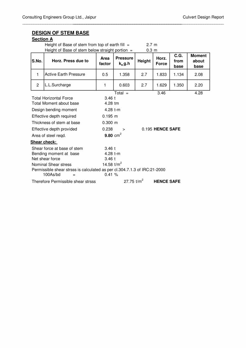
DESIGN OF STEM BASE
Section A
Height of Base of stem from top of earth fill = 2.7 m
Height of Base of stem below straight portion = 0.3 m
S.No.Area
factor
Pressure
ka.g.hHeight
Horz.
Force
C.G.
from
base
Moment
about
base
1 0.5 1.358 2.7 1.833 1.134 2.08
2 1 0.603 2.7 1.629 1.350 2.20
Total = 3.46 4.28
Total Horizontal Force 3.46 t
Total Moment about base 4.28 tm
Design bending moment 4.28 t-m
Effective depth required 0.195 m
Thickness of stem at base 0.300 m
Effective depth provided 0.238 > 0.195 HENCE SAFE
Area of steel reqd. 9.80 cm2
Shear force at base of stem 3.46 t
Bending moment at base 4.28 t-m
Net shear force 3.46 t
Nominal Shear stress 14.58 t/m2
Permissible shear strsss is calculated as per cl.304.7.1.3 of IRC:21-2000= 0.41 %
Therefore Permissible shear strsss 27.75 t/m2
HENCE SAFE
L.L.Surcharge
Shear check:
100As/bd
Horz. Press due to
Active Earth Pressure
Consulting Engineers Group Ltd., Jaipur
______________________________________________________________________
Culvert Design Report
__________________________________________________________________
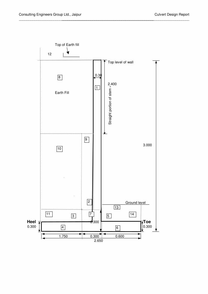
Top of Earth fill
Top level of wall
0.30
2.400
Earth Fill
3.000
Ground level
Heel 0.300 Toe0.300 0.300
1.750 0.300 0.600
2.650
Str
aig
ht
port
ion o
f ste
m =
9
13
2
3
4 6
5711 14
1
8
10
12

Consulting Engineers Group Ltd., Jaipur
______________________________________________________________________
Culvert Design Report
__________________________________________________________________
DESIGN OF RETAINING WALL FOR 3.000 m HEIGHTDESIGN DATA:
Top level of retaining wall = 3.000 m
Ground level = 1.200 m
Founding Level = 0.000 m
Total Height from top of wall to founding level = 3.000 m
Density of earth = 1.8 t/m3
Density of concrete = 2.4 t/m3
Clear cover to Reinforcement = 0.05 m
Clear cover to Reinforcement for foundations = 0.075 m
Grade of concrete = 25
Allowable stress in steel = 20380
Safe bearing capacity = 20 t/m2
Safety factor against overturning = 2.0
Safety factor against sliding = 1.5
Depth of L.L.Surcharge = 1.2 m
L.L.Surcharge on wall = 0 t/m^2
DESIGN CONSTANTS:
For Grade of concrete = M 25 & HYSD reinf. with Fe 415
Lever arm factor j = 0.902
Moment of resistance factor Q = 111.996
DIMENSIONS :
Length of Base of Retaining wall = 2.650 m
Section modulus = 1.170 m3
Length of Toe = 0.600 m
Length of Heel = 1.750 m
Thickness of Stem at base = 0.300 m
Thickness of straight portion of stem = 0.300 m
Ht. of straight portion of stem = 2.400 m
Minimum thickness of Toe slab = 0.300 m
Thickness of Toe slab at junction with stem = 0.300 m
Minimum thickness of heel slab = 0.300 m
Thickness of heel slab at junction with stem = 0.300 m
Angle of inclined stem with vertical = 0.000
Ht.of inclined potion of stem to base of footing = 0.600 m
Ht.of inclined potion of stem to top of footing = 0.300 m
Calculation of Earth pressure coefficients =
Angle of internal friction of soil φ = 30 deg = 0.5236 rad
Angle of wall friction δ = 20 deg = 0.3491 rad
Angle of incli . of soil at back i = 0 deg = 0.0000 rad
Angle of incli . of stem at back α = 90 deg = 1.570796 rad
Coefficient of active earth pressure ka = 0.297
Coefficient of horz.active earth pressure Kah = 0.279
Consulting Engineers Group Ltd., Jaipur
______________________________________________________________________
Culvert Design Report
__________________________________________________________________
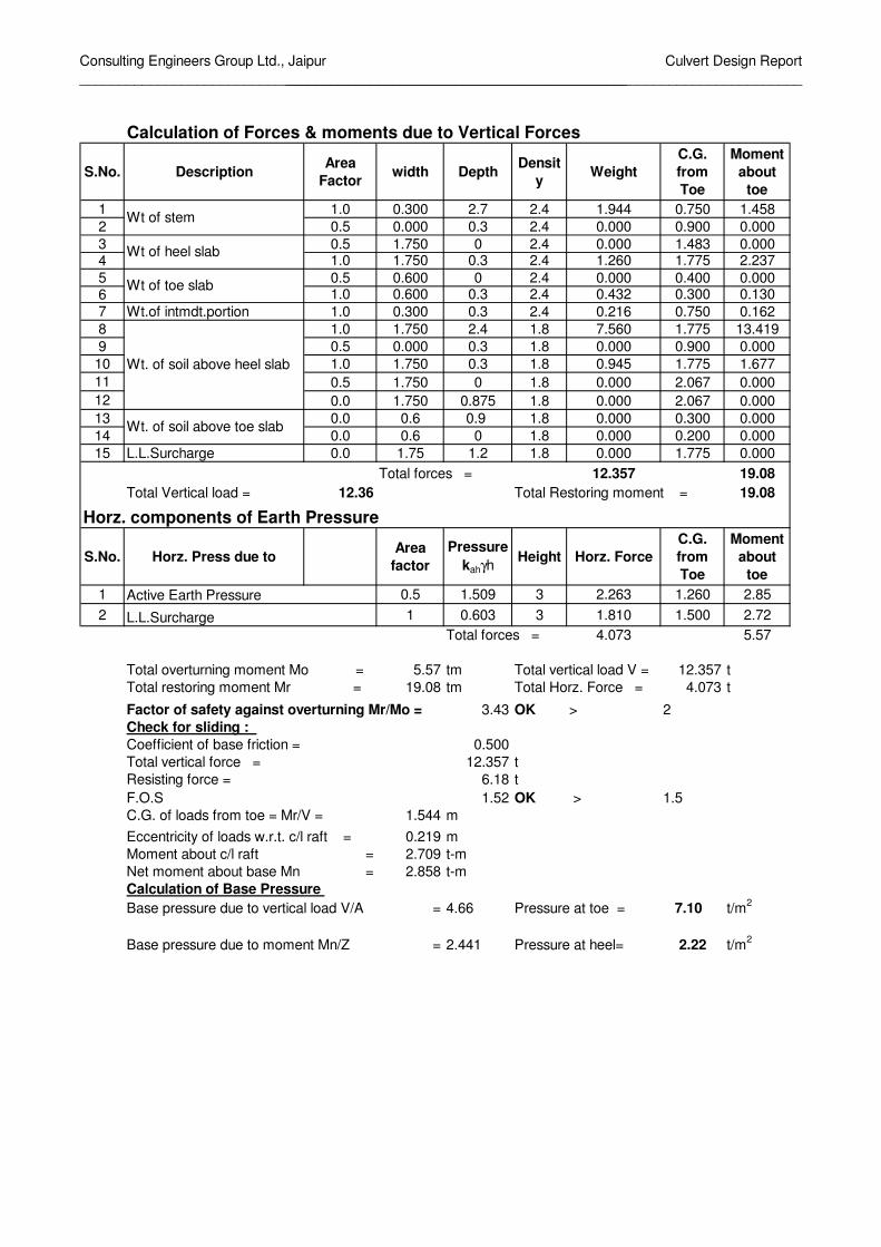
Calculation of Forces & moments due to Vertical Forces
S.No. DescriptionArea
Factorwidth Depth
Densit
yWeight
C.G.
from
Toe
Moment
about
toe
1 1.0 0.300 2.7 2.4 1.944 0.750 1.458
2 0.5 0.000 0.3 2.4 0.000 0.900 0.000
3 0.5 1.750 0 2.4 0.000 1.483 0.0004 1.0 1.750 0.3 2.4 1.260 1.775 2.237
5 0.5 0.600 0 2.4 0.000 0.400 0.0006 1.0 0.600 0.3 2.4 0.432 0.300 0.130
7 Wt.of intmdt.portion 1.0 0.300 0.3 2.4 0.216 0.750 0.162
8 1.0 1.750 2.4 1.8 7.560 1.775 13.419
9 0.5 0.000 0.3 1.8 0.000 0.900 0.000
10 1.0 1.750 0.3 1.8 0.945 1.775 1.677
11 0.5 1.750 0 1.8 0.000 2.067 0.000
12 0.0 1.750 0.875 1.8 0.000 2.067 0.000
13 0.0 0.6 0.9 1.8 0.000 0.300 0.000
14 0.0 0.6 0 1.8 0.000 0.200 0.000
15 L.L.Surcharge 0.0 1.75 1.2 1.8 0.000 1.775 0.000
Total forces = 12.357 19.08
Total Vertical load = 12.36 Total Restoring moment = 19.08
Horz. components of Earth Pressure
S.No. Horz. Press due to Area
factor
Pressure
kahγhHeight Horz. Force
C.G.
from
Toe
Moment
about
toe
1 0.5 1.509 3 2.263 1.260 2.85
2 1 0.603 3 1.810 1.500 2.72
Total forces = 4.073 5.57
5.57 tm Total vertical load V = 12.357 t
19.08 tm Total Horz. Force = 4.073 t
3.43 OK > 2
Check for sliding :
Coefficient of base friction = 0.500
Total vertical force = 12.357 t
Resisting force = 6.18 t
F.O.S 1.52 OK > 1.5
1.544 m
0.219 m
Moment about c/l raft = 2.709 t-m
Net moment about base Mn = 2.858 t-m
Calculation of Base Pressure
Base pressure due to vertical load V/A = 4.66 Pressure at toe = 7.10 t/m2
Base pressure due to moment Mn/Z = 2.441 Pressure at heel= 2.22 t/m2
Wt. of soil above heel slab
Active Earth Pressure
Wt of stem
Wt of heel slab
Wt of toe slab
Total overturning moment Mo =
Eccentricity of loads w.r.t. c/l raft =
Wt. of soil above toe slab
Factor of safety against overturning Mr/Mo =
C.G. of loads from toe = Mr/V =
Total restoring moment Mr =
L.L.Surcharge

Consulting Engineers Group Ltd., Jaipur
______________________________________________________________________
Culvert Design Report
__________________________________________________________________
CALCULATION OF DESIGN PRESSURES
1-1 2-2 3-3 4-4 5-5
7.104 5.999 5.446 2.222 6.705
0.720 0.720 5.580 5.580 0.720
6.384 5.279 -0.134 -3.358 5.985
** Positive net pressure means upward pressure & negative net pressure means downward pressure
4 3 2 5 1
d
Heel Toe
1.750 0.600
2.650
4 3 2 5 1
DESIGN OF TOE SLAB
Bending Moment at face of stem = 1.08 t-m
Effective depth required = 0.098 m
= 0.217 > reqd 0.098
Area of Reinforcement reqd.at bottom = 2.71 cm2
HENCE SAFE
= 2.37 t
Bending moment at sec 5-5 = 0.46 t-m
Net shear force at sec 5-5=S-Ms*tanβ/d1 = 2.37 t
Depth of slab at section 5-5 = 0.300 Effective depth d1 = 0.215 m
Nominal Shear stress = 7.90 t/m2
Permissible shear strsss is calculated as per cl.304.7.1.3 of IRC:21-2000
100As/bd = 0.126 %
Therefore Permissible shear strsss = 18.36 t/m2
HENCE SAFE
DESIGN OF HEEL SLAB3.50 t-m
Effective depth required = 0.177 m
0.215 m
Reinforcement reqd.at top = 8.85 cm2
3.06 t
Bending moment at face Ms = 3.50 t-m
Net shear force =S-Ms*tanβ/d1 = 3.06 t
Nominal Shear stress = 14.21 t/m2
Permissible shear strsss is calculated as per cl.304.7.1.3 of IRC:21-2000
100As/bd = 0.412 %
Therefore Permissible shear strsss = 27.71 t/m2
HENCE SAFE
Reinforcement calculation
Effective depth of slab at face of stem =
Shear force at face of stem S =
Effective depth provided at face of stem
Shear force at distance d from stem
Shear check:
Shear check:
Bending Moment at face of stem =
Section
Upward pressure
Downward Pressure
Net pressure

Consulting Engineers Group Ltd., Jaipur
______________________________________________________________________
Culvert Design Report
__________________________________________________________________
DESIGN OF STEM BASE
Section A
Height of Base of stem from top of earth fill = 2.7 m
Height of Base of stem below straight portion = 0.3 m
S.No.Area
factor
Pressure
ka.g.hHeight
Horz.
Force
C.G.
from
base
Moment
about
base
1 0.5 1.358 2.7 1.833 1.134 2.08
2 1 0.603 2.7 1.629 1.350 2.20
Total = 3.46 4.28
Total Horizontal Force 3.46 t
Total Moment about base 4.28 tm
Design bending moment 4.28 t-m
Effective depth required 0.195 m
Thickness of stem at base 0.300 m
Effective depth provided 0.238 > 0.195 HENCE SAFE
Area of steel reqd. 9.80 cm2
Shear force at base of stem 3.46 t
Bending moment at base 4.28 t-m
Net shear force 3.46 t
Nominal Shear stress 14.58 t/m2
Permissible shear strsss is calculated as per cl.304.7.1.3 of IRC:21-2000= 0.41 %
Therefore Permissible shear strsss 27.75 t/m2
HENCE SAFE
L.L.Surcharge
Shear check:
100As/bd
Horz. Press due to
Active Earth Pressure

Consulting Engineers Group Ltd., Jaipur
___________________________________________________________________________
Culvert Design Report
____________________________________________________
Top of Earth fill
Top level of wall
0.30
2.400
Earth Fill
4.000
Ground level
Heel 0.450 Toe0.300 0.300
2.040 0.410 0.700
3.150
Str
aig
ht
port
ion o
f ste
m =
9
13
2
3
4 6
5711 14
1
8
10
12

Consulting Engineers Group Ltd., Jaipur
___________________________________________________________________________
Culvert Design Report
____________________________________________________
DESIGN OF RETAINING WALL FOR 4.000 m HEIGHTDESIGN DATA:
Top level of retaining wall = 4.000 m
Ground level = 1.500 m
Founding Level = 0.000 m
Total Height from top of wall to founding level = 4.000 m
Density of earth = 1.8 t/m3
Density of concrete = 2.4 t/m3
Clear cover to Reinforcement = 0.05 m
Clear cover to Reinforcement for foundations = 0.075 m
Grade of concrete = 20
Allowable stress in steel = 20380
Safe bearing capacity = 20 t/m2
Safety factor against overturning = 2.0
Safety factor against sliding = 1.5
Depth of L.L.Surcharge = 1.2 m
L.L.Surcharge on wall = 0 t/m^2
DESIGN CONSTANTS:
For Grade of concrete = M 20 & HYSD reinf. with Fe 415
Lever arm factor j = 0.916
Moment of resistance factor Q = 78.54
DIMENSIONS :
Length of Base of Retaining wall = 3.150 m
Section modulus = 1.654 m3
Length of Toe = 0.700 m
Length of Heel = 2.040 m
Thickness of Stem at base = 0.410 m
Thickness of straight portion of stem = 0.300 m
Ht. of straight portion of stem = 2.400 m
Minimum thickness of Toe slab = 0.300 m
Thickness of Toe slab at junction with stem = 0.450 m
Minimum thickness of heel slab = 0.300 m
Thickness of heel slab at junction with stem = 0.450 m
Angle of inclined stem with vertical = 0.096
Ht.of inclined potion of stem to base of footing = 1.600 m
Ht.of inclined potion of stem to top of footing = 1.150 m
Calculation of Earth pressure coefficients =
Angle of internal friction of soil φ = 30 deg = 0.524 rad
Angle of wall friction δ = 20 deg = 0.349 rad
Angle of incli . of soil at back i = 0 deg = 0.000 rad
Angle of incli . of stem at back α = 90 deg = 1.57080 rad
Coefficient of active earth pressure ka = 0.297
Coefficient of horz.active earth pressure Kah = 0.279

Consulting Engineers Group Ltd., Jaipur
___________________________________________________________________________
Culvert Design Report
____________________________________________________
Calculation of Forces & moments due to Vertical Forces
S.N
o.Description
Area
Factorwidth Depth Density Weight
C.G.
from
Toe
Moment
about
toe1 1.0 0.300 3.55 2.4 2.556 0.850 2.173
2 0.5 0.110 1.15 2.4 0.152 1.037 0.157
3 0.5 2.040 0.15 2.4 0.367 1.790 0.6574 1.0 2.040 0.3 2.4 1.469 2.130 3.129
5 0.5 0.700 0.15 2.4 0.126 0.467 0.0596 1.0 0.700 0.3 2.4 0.504 0.350 0.176
7 Wt.of intmdt.portion 1.0 0.410 0.45 2.4 0.443 0.905 0.401
8 1.0 2.150 2.4 1.8 9.288 2.075 19.273
9 0.5 0.110 1.15 1.8 0.114 1.073 0.122
10 1.0 2.040 1.15 1.8 4.223 2.130 8.995
11 0.5 2.040 0.15 1.8 0.275 2.470 0.680
12 0.0 2.150 1.075 1.8 0.000 2.434 0.000
13 0.0 0.7 1.1 1.8 0.000 0.350 0.000
14 0.0 0.7 0.15 1.8 0.000 0.233 0.000
15 L.L.Surcharge 0.0 2.15 1.2 1.8 0.000 2.075 0.000
Total forces = 19.517 35.82
Total Vertical load = 19.52 Total Restoring moment = 35.82
Horz. components of Earth Pressure
S.N
o.Horz. Press due to
Area
factor
Pressure
kahγhHeight Horz. Force
C.G.
from
Toe
Moment
about
toe
1 0.5 2.012 4 4.023 1.680 6.76
2 1 0.603 4 2.414 2.000 4.83
Total forces = 6.437 11.59
11.59 tm Total vertical load V = 19.517 t
35.82 tm Total Horz. Force = 6.437 t
3.09 OK > 2
Check for sliding :
Coefficient of base friction = 0.500
Total vertical force = 19.517 t
Resisting force = 9.76 t
F.O.S 1.52 OK > 1.5
1.835 m
0.260 m
Moment about c/l raft = 5.083 t-m
Net moment about base Mn = 6.504 t-m
Calculation of Base Pressure
Base pressure due to vertical load V/A = 6.20 Pressure at toe = 10.13 t/m2
Base pressure due to moment Mn/Z = 3.933 Pressure at heel= 2.26 t/m2
Wt. of soil above heel slab
Active Earth Pressure
Wt of stem
Wt of heel slab
Wt of toe slab
Total overturning moment Mo =
Eccentricity of loads w.r.t. c/l raft =
Wt. of soil above toe slab
Factor of safety against overturning Mr/Mo =
C.G. of loads from toe = Mr/V =
Total restoring moment Mr =
L.L.Surcharge

Consulting Engineers Group Ltd., Jaipur
___________________________________________________________________________
Culvert Design Report
____________________________________________________
CALCULATION OF DESIGN PRESSURES
1-1 2-2 3-3 4-4 5-5
10.129 8.381 7.357 2.263 9.212
0.720 1.080 7.470 7.380 0.891
9.409 7.301 -0.113 -5.117 8.321
** Positive net pressure means upward pressure & negative net pressure means downward pressure
4 3 2 5 1
d
Heel Toe
2.040 0.700
3.150
4 3 2 5 1
DESIGN OF TOE SLAB
Bending Moment at face of stem = 2.13 t-m
Effective depth required = 0.165 m
= 0.367 > reqd 0.165
Area of Reinforcement reqd.at bottom = 3.11 cm2 HENCE SAFE
= 2.95 t
Bending moment at sec 5-5 = 0.50 t-m
Net shear force at sec 5-5=S-Ms*tanβ/d1 = 2.58 t
Depth of slab at section 5-5 = 0.371 Effective depth d1 = 0.286 m
Nominal Shear stress = 6.94 t/m2
Permissible shear strsss is calculated as per cl.304.7.1.3 of IRC:21-2000
100As/bd = 0.109 %
Therefore Permissible shear strsss = 18.36 t/m2 HENCE SAFE
DESIGN OF HEEL SLAB7.18 t-m
Effective depth required = 0.302 m
0.365 m
Reinforcement reqd.at top = 10.53 cm2
5.33 t
Bending moment at face Ms = 7.18 t-m
Net shear force =S-Ms*tanβ/d1 = 3.89 t
Nominal Shear stress = 10.65 t/m2
Permissible shear strsss is calculated as per cl.304.7.1.3 of IRC:21-2000
100As/bd = 0.289 %
Therefore Permissible shear strsss = 23.70 t/m2 HENCE SAFE
FOR CURTAILMENT
Shear Force at distance from stem = 123.873
Bending Moment at distance 2.000 m from face of stem = 0.00
Effective depth required = 0.007 m
Effective depth provided = 0.220 > reqd 0.007
Curtailment Length = 2.220
Area of Reinforcement reqd.at bottom = 0.01 cm2
Reinforcement calculation
Effective depth of slab at face of stem =
Shear force at face of stem S =
Effective depth provided at face of stem
Shear force at distance d from stem
Shear check:
Shear check:
Bending Moment at face of stem =
Section
Upward pressure
Downward Pressure
Net pressure
Consulting Engineers Group Ltd., Jaipur
___________________________________________________________________________
Culvert Design Report
____________________________________________________
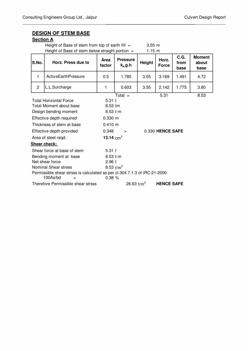
DESIGN OF STEM BASE
Section A
Height of Base of stem from top of earth fill = 3.55 m
Height of Base of stem below straight portion = 1.15 m
S.No.Area
factor
Pressure
ka.g.hHeight
Horz.
Force
C.G.
from
base
Moment
about
base
1 0.5 1.785 3.55 3.169 1.491 4.72
2 1 0.603 3.55 2.142 1.775 3.80
Total = 5.31 8.53
Total Horizontal Force 5.31 t
Total Moment about base 8.53 tm
Design bending moment 8.53 t-m
Effective depth required 0.330 m
Thickness of stem at base 0.410 m
Effective depth provided 0.348 > 0.330 HENCE SAFE
Area of steel reqd. 13.14 cm2
Shear force at base of stem 5.31 t
Bending moment at base 8.53 t-m
Net shear force 2.96 t
Nominal Shear stress 8.53 t/m2
Permissible shear strsss is calculated as per cl.304.7.1.3 of IRC:21-2000= 0.38 %
Therefore Permissible shear strsss 26.63 t/m2 HENCE SAFE
L.L.Surcharge
Shear check:
100As/bd
Horz. Press due to
ActiveEarthPressure

Consulting Engineerts Group Ltd., Jaipur
________________________________________________________________________
Culvert Design Report
______________________________________________________
Top of Earth fill
Top level of wall
0.30
2.400
Earth Fill
5.000
Ground level
Heel 0.500 Toe0.300 0.300
2.680 0.550 1.000
4.230
Str
aig
ht
port
ion o
f ste
m =
9
13
2
3
4 6
5711 14
1
8
10
12

Consulting Engineerts Group Ltd., Jaipur
________________________________________________________________________
Culvert Design Report
______________________________________________________
DESIGN OF RETAINING WALL FOR 5.000 m HEIGHTDESIGN DATA:
Top level of retaining wall = 5.000 m
Ground level = 1.500 m
Founding Level = 0.000 m
Total Height from top of wall to founding level = 5.000 m
Density of earth = 1.8 t/m3
Density of concrete = 2.4 t/m3
Clear cover to Reinforcement = 0.05 m
Clear cover to Reinforcement for foundations = 0.075 m
Grade of concrete = 20
Allowable stress in steel = 20380
Safe bearing capacity = 20 t/m2
Safety factor against overturning = 2.0
Safety factor against sliding = 1.5
Depth of L.L.Surcharge = 1.2 m
L.L.Surcharge on wall = 0 t/m^2
DESIGN CONSTANTS:
For Grade of concrete = M 20 & HYSD reinf. with Fe 415
Lever arm factor j = 0.916
Moment of resistance factor Q = 78.54
DIMENSIONS :Length of Base of Retaining wall = 4.230 m
Section modulus = 2.982 m3
Length of Toe = 1.000 m
Length of Heel = 2.680 m
Thickness of Stem at base = 0.550 m
Thickness of straight portion of stem = 0.300 m
Ht. of straight portion of stem = 2.400 m
Minimum thickness of Toe slab = 0.300 m
Thickness of Toe slab at junction with stem = 0.500 m
Minimum thickness of heel slab = 0.300 m
Thickness of heel slab at junction with stem = 0.500 m
Angle of inclined stem with vertical = 0.119
Ht.of inclined potion of stem to base of footing = 2.600 m
Ht.of inclined potion of stem to top of footing = 2.100 m
Calculation of Earth pressure coefficients =
Angle of internal friction of soil φ = 30 deg = 0.524 rad
Angle of wall friction δ = 20 deg = 0.349 rad
Angle of incli . of soil at back i = 0 deg = 0.000 rad
Angle of incli . of stem at back α = 90 deg = 1.571 rad
Coefficient of active earth pressure ka = 0.297
Coefficient of horz.active earth pressure Kah = 0.279
Consulting Engineerts Group Ltd., Jaipur
________________________________________________________________________
Culvert Design Report
______________________________________________________
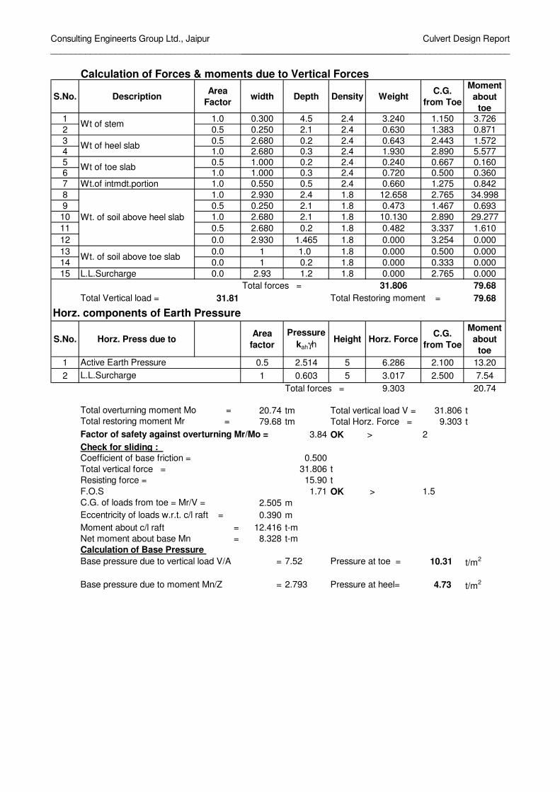
Calculation of Forces & moments due to Vertical Forces
S.No. DescriptionArea
Factorwidth Depth Density Weight
C.G.
from Toe
Moment
about
toe1 1.0 0.300 4.5 2.4 3.240 1.150 3.726
2 0.5 0.250 2.1 2.4 0.630 1.383 0.871
3 0.5 2.680 0.2 2.4 0.643 2.443 1.5724 1.0 2.680 0.3 2.4 1.930 2.890 5.577
5 0.5 1.000 0.2 2.4 0.240 0.667 0.1606 1.0 1.000 0.3 2.4 0.720 0.500 0.360
7 Wt.of intmdt.portion 1.0 0.550 0.5 2.4 0.660 1.275 0.842
8 1.0 2.930 2.4 1.8 12.658 2.765 34.998
9 0.5 0.250 2.1 1.8 0.473 1.467 0.693
10 1.0 2.680 2.1 1.8 10.130 2.890 29.277
11 0.5 2.680 0.2 1.8 0.482 3.337 1.610
12 0.0 2.930 1.465 1.8 0.000 3.254 0.000
13 0.0 1 1.0 1.8 0.000 0.500 0.000
14 0.0 1 0.2 1.8 0.000 0.333 0.000
15 L.L.Surcharge 0.0 2.93 1.2 1.8 0.000 2.765 0.000
Total forces = 31.806 79.68
Total Vertical load = 31.81 Total Restoring moment = 79.68
Horz. components of Earth Pressure
S.No. Horz. Press due to Area
factor
Pressure
kahγhHeight Horz. Force
C.G.
from Toe
Moment
about
toe
1 0.5 2.514 5 6.286 2.100 13.20
2 1 0.603 5 3.017 2.500 7.54
Total forces = 9.303 20.74
20.74 tm Total vertical load V = 31.806 t
79.68 tm Total Horz. Force = 9.303 t
3.84 OK > 2
Check for sliding :
Coefficient of base friction = 0.500
Total vertical force = 31.806 t
Resisting force = 15.90 t
F.O.S 1.71 OK > 1.5
2.505 m
0.390 m
Moment about c/l raft = 12.416 t-m
Net moment about base Mn = 8.328 t-m
Calculation of Base Pressure
Base pressure due to vertical load V/A = 7.52 Pressure at toe = 10.31 t/m2
Base pressure due to moment Mn/Z = 2.793 Pressure at heel= 4.73 t/m2
Wt. of soil above heel slab
Active Earth Pressure
Wt of stem
Wt of heel slab
Wt of toe slab
Total overturning moment Mo =
Eccentricity of loads w.r.t. c/l raft =
Wt. of soil above toe slab
Factor of safety against overturning Mr/Mo =
C.G. of loads from toe = Mr/V =
Total restoring moment Mr =
L.L.Surcharge

Consulting Engineerts Group Ltd., Jaipur
________________________________________________________________________
Culvert Design Report
______________________________________________________
CALCULATION OF DESIGN PRESSURES
1-1 2-2 3-3 4-4 5-5
10.312 8.991 8.265 4.726 9.761
0.720 1.200 9.300 9.180 1.000
9.592 7.791 -1.035 -4.454 8.761
** Positive net pressure means upward pressure & negative net pressure means downward pressure
4 3 2 5 1
d
Heel Toe
2.680 1.000
4.230
4 3 2 5 1
DESIGN OF TOE SLAB
Bending Moment at face of stem = 4.50 t-m
Effective depth required = 0.239 m
= 0.417 > reqd 0.239
Area of Reinforcement reqd.at bottom = 5.78 cm2 HENCE SAFE
= 5.35 t
Bending moment at sec 5-5 = 1.58 t-m
Net shear force at sec 5-5=S-Ms*tanβ/d1 = 4.40 t
Depth of slab at section 5-5 = 0.417 Effective depth d1 = 0.332 m
Nominal Shear stress = 10.55 t/m2
Permissible shear strsss is calculated as per cl.304.7.1.3 of IRC:21-2000
100As/bd = 0.174 %
Therefore Permissible shear strsss = 19.35 t/m2 HENCE SAFE
DESIGN OF HEEL SLAB11.90 t-m
Effective depth required = 0.389 m
0.415 m
Reinforcement reqd.at top = 15.36 cm2
7.35 t
Bending moment at face Ms = 11.90 t-m
Net shear force =S-Ms*tanβ/d1 = 5.21 t
Nominal Shear stress = 12.57 t/m2
Permissible shear strsss is calculated as per cl.304.7.1.3 of IRC:21-2000
100As/bd = 0.370 %
Therefore Permissible shear strsss = 26.36 t/m2 HENCE SAFE
FOR CURTAILMENT
Shear Force at distance from stem = 2.259
Bending Moment at distance 1.500 m from face of stem = 2.27
Effective depth required = 0.170 m
Effective depth provided = 0.305 > reqd 0.170
Curtailment Length = 1.805
Area of Reinforcement reqd.at bottom = 3.99 cm2
Reinforcement calculation
Effective depth of slab at face of stem =
Shear force at face of stem S =
Effective depth provided at face of stem
Shear force at distance d from stem
Shear check:
Shear check:
Bending Moment at face of stem =
Section
Upward pressure
Downward Pressure
Net pressure

Consulting Engineerts Group Ltd., Jaipur
________________________________________________________________________
Culvert Design Report
______________________________________________________
DESIGN OF STEM BASE
Section A
Height of Base of stem from top of earth fill = 4.5 m
Height of Base of stem below straight portion = 2.1 m
S.No.Area
factor
Pressure
ka.g.hHeight
Horz.
Force
C.G.
from
base
Moment
about
base
1 0.5 2.263 4.5 5.092 1.890 9.62
2 1 0.603 4.5 2.716 2.250 6.11
Total = 7.81 15.73
Total Horizontal Force 7.81 t
Total Moment about base 15.73 tm
Design bending moment 15.73 t-m
Effective depth required 0.448 m
Thickness of stem at base 0.550 m
Effective depth provided 0.488 > 0.448 HENCE SAFE
Area of steel reqd. 17.29 cm2
Shear force at base of stem 7.81 t
Bending moment at base 15.73 t-m
Net shear force 3.97 t
Nominal Shear stress 8.13 t/m2
Permissible shear strsss is calculated as per cl.304.7.1.3 of IRC:21-2000= 0.35 %
Therefore Permissible shear strsss 25.86 t/m2 HENCE SAFE
L.L.Surcharge
Shear check:
100As/bd
Horz. Press due to
ActiveEarthPressure

Consulting Engineers Group Ltd., Jaipur
_______________________________________________________________
Culvert Design Report
_______________________________________________________
Top of Earth fill
Top level of wall
0.30
2.400
Earth Fill
6.000
Ground level
Heel 0.600 Toe0.300 0.300
3.06 0.700 1.175
4.935
Str
aig
ht
port
ion o
f ste
m =
9
13
2
3
4 6
5711 14
1
8
10
12

Consulting Engineers Group Ltd., Jaipur
_______________________________________________________________
Culvert Design Report
_______________________________________________________
DESIGN OF RETAINING WALL FOR 6.000 m HEIGHT
DESIGN DATA:
Top level of retaining wall = 6.000 m
Ground level = 1.500 m
Founding Level = 0.000 m
Total Height from top of wall to founding level = 6.000 m
Density of earth = 1.8 t/m3
Density of concrete = 2.4 t/m3
Clear cover to Reinforcement = 0.05 m
Clear cover to Reinforcement for foundations = 0.075 m
Grade of concrete = 20
Allowable stress in steel = 20380
Safe bearing capacity = 20 t/m2
Safety factor against overturning = 2.0
Safety factor against sliding = 1.5
Depth of L.L.Surcharge = 1.2 m
L.L.Surcharge on wall = 0 t/m^2
DESIGN CONSTANTS:
For Grade of concrete = M 20 & HYSD reinf. with Fe 415
Lever arm factor j = 0.916
Moment of resistance factor Q = 78.54
DIMENSIONS :Length of Base of Retaining wall = 4.935 m
Section modulus = 4.059 m3
Length of Toe = 1.175 m
Length of Heel = 3.060 m
Thickness of Stem at base = 0.700 m
Thickness of straight portion of stem = 0.300 m
Ht. of straight portion of stem = 2.400 m
Minimum thickness of Toe slab = 0.300 m
Thickness of Toe slab at junction with stem = 0.600 m
Minimum thickness of heel slab = 0.300 m
Thickness of heel slab at junction with stem = 0.600 m
Angle of inclined stem with vertical = 0.133
Ht.of inclined potion of stem to base of footing = 3.600 m
Ht.of inclined potion of stem to top of footing = 3.000 m
Calculation of Earth pressure coefficients =
Angle of internal friction of soil φ = 30 deg = 0.524 rad
Angle of wall friction δ = 20 deg = 0.349 rad
Angle of incli . of soil at back i = 0 deg = 0.000 rad
Angle of incli . of stem at back α = 90 deg = 1.571 rad
Coefficient of active earth pressure ka = 0.297
Coefficient of horz.active earth pressure Kah = 0.279

Consulting Engineers Group Ltd., Jaipur
_______________________________________________________________
Culvert Design Report
_______________________________________________________
Calculation of Forces & moments due to Vertical Forces
S.No. DescriptionArea
Factorwidth Depth Density Weight
C.G.
from
Toe
Moment
about
toe1 1.0 0.300 5.4 2.4 3.888 1.325 5.152
2 0.5 0.400 3 2.4 1.440 1.608 2.316
3 0.5 3.060 0.3 2.4 1.102 2.895 3.1894 1.0 3.060 0.3 2.4 2.203 3.405 7.502
5 0.5 1.175 0.3 2.4 0.423 0.783 0.3316 1.0 1.175 0.3 2.4 0.846 0.588 0.497
7 Wt.of intmdt.portion 1.0 0.700 0.6 2.4 1.008 1.525 1.537
8 1.0 3.460 2.4 1.8 14.947 3.205 47.906
9 0.5 0.400 3 1.8 1.080 1.742 1.881
10 1.0 3.060 3 1.8 16.524 3.405 56.264
11 0.5 3.060 0.3 1.8 0.826 3.915 3.235
12 0.0 3.460 1.73 1.8 0.000 3.783 0.000
13 0.0 1.175 0.9 1.8 0.000 0.588 0.000
14 0.0 1.175 0.3 1.8 0.000 0.392 0.000
15 L.L.Surcharge 0.0 3.46 1.2 1.8 0.000 3.205 0.000
Total forces = 44.287 129.81
Total Vertical load = 44.29 Total Restoring moment = 129.81
Horz. components of Earth Pressure
S.No.Area
factor
Pressure
kahγhHeight Horz. Force
C.G.
from
Toe
Moment
about
toe
1 0.5 3.017 6 9.052 2.520 22.81
2 1 0.603 6 3.621 3.000 10.86
Total forces = 12.673 33.67
33.67 tm Total vertical load V = 44.287 t
129.81 tm Total Horz. Force = 12.673 t
3.85 OK > 2
Check for sliding :
Coefficient of base friction = 0.500
Total vertical force = 44.287 t
Resisting force = 22.14 t
F.O.S 1.75 OK > 1.5
2.931 m
0.464 m
Moment about c/l raft = 20.531 t-m
Net moment about base Mn = 13.142 t-m
Calculation of Base Pressure
Base pressure due to vertical load V/A = 8.97 Pressure at toe = 12.21 t/m2
Base pressure due to moment Mn/Z = 3.238 Pressure at heel= 5.74 t/m2
Total overturning moment Mo =
Eccentricity of loads w.r.t. c/l raft =
Wt. of soil above toe slab
Factor of safety against overturning Mr/Mo =
C.G. of loads from toe = Mr/V =
Total restoring moment Mr =
L.L.Surcharge
Wt. of soil above heel slab
Active Earth Pressure
Horz. Press due to
Wt of stem
Wt of heel slab
Wt of toe slab
Consulting Engineers Group Ltd., Jaipur
_______________________________________________________________
Culvert Design Report
_______________________________________________________
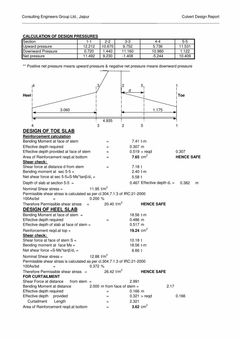
CALCULATION OF DESIGN PRESSURES
1-1 2-2 3-3 4-4 5-5
12.212 10.670 9.752 5.736 11.531
0.720 1.440 11.160 10.980 1.122
11.492 9.230 -1.408 -5.244 10.409
** Positive net pressure means upward pressure & negative net pressure means downward pressure
4 3 2 5 1
d
Heel Toe
3.060 1.175
4.935
4 3 2 5 1
DESIGN OF TOE SLAB
Bending Moment at face of stem = 7.41 t-m
Effective depth required = 0.307 m
= 0.519 > reqd 0.307
Area of Reinforcement reqd.at bottom = 7.65 cm2
HENCE SAFE
= 7.18 t
Bending moment at sec 5-5 = 2.40 t-m
Net shear force at sec 5-5=S-Ms*tanβ/d1 = 5.58 t
Depth of slab at section 5-5 = 0.467 Effective depth d1 = 0.382 m
Nominal Shear stress = 11.95 t/m2
Permissible shear strsss is calculated as per cl.304.7.1.3 of IRC:21-2000
100As/bd = 0.200 %
Therefore Permissible shear strsss = 20.40 t/m2
HENCE SAFE
DESIGN OF HEEL SLAB18.56 t-m
Effective depth required = 0.486 m
0.517 m
Reinforcement reqd.at top = 19.24 cm2
10.18 t
Bending moment at face Ms = 18.56 t-m
Net shear force =S-Ms*tanβ/d1 = 6.66 t
Nominal Shear stress = 12.88 t/m2
Permissible shear strsss is calculated as per cl.304.7.1.3 of IRC:21-2000
100As/bd = 0.372 %
Therefore Permissible shear strsss = 26.42 t/m2
HENCE SAFE
FOR CURTAILMENT
Shear Force at distance from stem = 2.991
Bending Moment at distance 2.000 m from face of stem = 2.17
Effective depth required = 0.166 m
Effective depth provided = 0.321 > reqd 0.166
Curtailment Length = 2.321
Area of Reinforcement reqd.at bottom = 3.62 cm2
Section
Upward pressure
Downward Pressure
Net pressure
Reinforcement calculation
Effective depth of slab at face of stem =
Shear force at face of stem S =
Effective depth provided at face of stem
Shear force at distance d from stem
Shear check:
Shear check:
Bending Moment at face of stem =

Consulting Engineers Group Ltd., Jaipur
_______________________________________________________________
Culvert Design Report
_______________________________________________________
DESIGN OF STEM BASE
Section A
Height of Base of stem from top of earth fill = 5.4 m
Height of Base of stem below straight portion = 3 m
S.No.Area
factor
Pressure
ka.g.hHeight
Horz.
Force
C.G.
from
base
Moment
about
base
1 0.5 2.716 5.4 7.332 2.268 16.63
2 1 0.603 5.4 3.259 2.700 8.80
Total = 10.59 25.43
Total Horizontal Force 10.59 t
Total Moment about base 25.43 tm
Design bending moment 25.43 t-m
Effective depth required 0.569 m
Thickness of stem at base 0.700 m
Effective depth provided 0.640 > 0.569 HENCE SAFE
Area of steel reqd. 21.28 cm2
Shear force at base of stem 10.59 t
Bending moment at base 25.43 t-m
Net shear force 5.29 t
Nominal Shear stress 8.27 t/m2
Permissible shear strsss is calculated as per cl.304.7.1.3 of IRC:21-2000= 0.33 %
Therefore Permissible shear strsss 25.13 t/m2
HENCE SAFE
L.L.Surcharge
Horz. Press due to
ActiveEarthPressure
Shear check:
100As/bd