orion proposal january 25, 2001 executive summary ... · orion proposal january 25, 2001 executive...
TRANSCRIPT

ORION Proposal January 25, 2001 Executive Summary
Executive Summary Page 1 of 3
Executive Summary: The ORION Center for Advanced Accelerator and Beam Physics Particle physics is addressing fundamental questions of the origin of mass and the
observed symmetries in nature. Historically, these types of questions have been answered at the energy frontier, and exponential growth of center-of-mass energy and discoveries have gone hand-in-hand. Advanced accelerator research, with its goal of understanding the physics and developing the technologies for reaching higher energies, is essential for the future of particle physics. There are advanced accelerator concepts based on plasmas, lasers, high-gradient radio frequency structures, and novel technologies. They have significant promise of continuing the growth in available energy and, with it, profound new insights into nature. These concepts cover physics and engineering well beyond traditional accelerator physics, and they appeal to a broad spectrum of faculty, scientists and students who bring diverse intellectual inquiry to bear.
This is a proposal from a Stanford/UCLA/USC collaboration for a Physics Frontiers Center, called the ORION Center, devoted to advanced accelerator and beam physics research. It includes performing a wide range of experiments, building a shared, user-oriented facility, and developing and using supercomputing expertise and resources that are the equivalent of the experimental facilities. This Center directly addresses crucially important new accelerator ideas written about in a January 2001 PHYSICS TODAY article where it says�� more new ideas are needed, for which we need more intellectual resources and support for them.� The Principal Investigators are recognized leaders in conventional accelerators, lasers, plasmas, particle source physics, and computer simulation, and this breadth is a key attribute of the Center. The ORION Center will bring them together in a research program that holds promise for significant advances through rapid assessment and development of new acceleration concepts.
The foundation of the ORION Center will be specialized accelerators and infrastructure at the Stanford Linear Accelerator Center (SLAC) that will be available to the Center and will highly leverage the NSF investment in it. The Stanford Synchrotron Radiation Laboratory (SSRL) provides a precedent for a center-like initiative funded by the NSF, operated by a university, and taking advantage of unique SLAC facilities. SSRL was a singular success, and subsequently it made a transition from NSF to DOE funding.
Research will begin, at inception of the Center, with experiments at the Final Focus Test Beam (FFTB), which is an extensively instrumented beamline at the end of the SLAC main linac that can deliver 30 GeV electron and positron beams. The FFTB will be available for two or three more years until it is needed for synchrotron radiation research. It is an exceptional facility for experiments in non-linear positron/matter and electron/matter interactions. Understanding these interactions is crucial for plasma based high-energy colliders, and these experiments are an integral part of the ORION Center.
In the longer-term, the experimental activities will be concentrated at the ORION Facility for advanced accelerator research funded through the Center. The ORION Facility will be based on the Next Linear Collider Test Accelerator (NLCTA), an operating linac at SLAC capable of providing beams from 50 up to a nominal 350 MeV energy. The ORION Facility will include experimental halls, beam lines, lasers, laser rooms, and a new electron source. It will be a user-oriented facility for advanced accelerator research that will be open to experimenters studying all aspects of advanced accelerator science and technology. It will be a focus of the Principal Investigator�s research programs, and, in addition, it will be available to other researchers through proposal solicitation and peer review. Experiments will be provided beams, instrumentation, and other resources, and experimenters will be able to concentrate on new and novel physics and technology. By providing these resources and making rapid progress possible,

ORION Proposal January 25, 2001 Executive Summary
Executive Summary Page 2 of 3
ORION will bring together a critical-mass from a diverse scientific community with a passion for advanced accelerator research.
Scientific research progresses most efficiently with close contact between experiment and theory through either calculations or numerical simulation. Supercomputing has proven to be an extremely powerful research method for advanced accelerator physics. We are proposing to develop a hierarchy of codes, from fully explicit to quasi-static reduced-description ones for understanding many physics issues from first principles. In addition, numerical models with a user-friendly interface will be developed to run on inexpensive parallel computers. This research will require major advances in reduced-description physics models, parallel algorithms, user-friendly interfaces, visualization, and the basic physics of GeV class beams. Supercomputing activities will take place at the experiments on a small cluster at SLAC and also remotely at UCLA/USC.
Advanced accelerator research is attractive to young scientists because of the combination of forefront computer-based research, state-of-the-art technologies, the many opportunities for creativity, and the potential of contribution to particle physics. For similar reasons, undergraduate and graduate research and education programs have proven quite attractive. The groups involved with this proposal have traditions of high-quality education as integral parts of their activities, and the American Physical Society and the Institute of Electrical and Electronics Engineers have recognized their students� accomplishments.
The education outreach program will go beyond these traditional educational activities through partnerships with interested, local community colleges that involve their faculty and students in the Center. The major goal of these partnerships will be to increase the number of students in physics and engineering that transfer to four-year colleges and universities. Community college faculty will be invited to work together with members of the Center to develop a plan that would best serve their students and integrate the Center�s science into their teaching programs. Students will be offered support and opportunities that will then allow them to develop working relationships with expert partners that sponsor meaningful contributions to the Center. In addition, we will develop an ORION website and all ORION research projects will provide web-based descriptions and content that is targeted at high school and community college students. This website, together with public lectures, tours and exhibits, also provides a complementary community outreach program that is described in more detail in the proposal.
The Center will be a major facility for advanced accelerator research. Substantial interest has been expressed by several laboratories in addition to SLAC and by users interested in collaboration and/or independent experiments. ORION will be managed in a way that reflects the objectives of the Center and the crucial investments being made in it by the NSF, the Principal Investigators (PI�s), SLAC, and the other laboratories. A Board, consisting of the PI�s and representatives from SLAC and other participating laboratories, will function like the leadership of a major scientific collaboration and, in addition, have reporting responsibilities to the Stanford Dean of Research. Beam time allocation will be modeled after common practices in the synchrotron radiation community: the Center�s developers will have 75% of the time for their research, and the remainder will be available to a general user community and allocated based upon proposal review by an external Program Committee.
ORION has potential impacts at different levels. The physics will be diverse with
scientists pursuing research in an evolving program as results indicate new avenues. Possible results include the study of non-linear positron/matter interactions, beam physics of ultra-short

ORION Proposal January 25, 2001 Executive Summary
Executive Summary Page 3 of 3
pulse electron sources, direct laser acceleration, x-ray generation via beam-plasma interactions, and simulation and visualization integrated with experiments. These results are interesting in themselves, and, in addition, they could be valuable for a variety of sciences. The ion-channel laser, the laser driven Free Electron Laser, and the astrophysics implications of the positron-plasma interaction results are examples.
However, the overriding ambition is to perform research that will extend the energy available for particle physics. The user-orientation, breadth and complementary facilities offered by the ORION Center are crucial to realize this ambition. The plasma �Afterburner�, discussed in Major Research Component 1, and a lithographically fabricated, laser driven accelerator, discussed in Major Research Component 4, are examples from the proposal. Exploring the first of these ideas involves experiments at the FFTB, plasma experiments at the ORION Facility, and extensive computer modeling. The second relies on the beams and diagnostics that will be available at ORION for exploring the impact of the dynamic and rapidly growing optoelectronics industry on acceleration. These ideas and others that will arise are speculative, and which, if any, could be a breakthrough cannot be known. But, ORION is needed to explore them.

ORION Proposal January 25, 2001 Achievements
Achievements Page 1 of 3
Achievements under Prior NSF Support In 1995, Prof. R. Byer initiated a research program based on laser acceleration in a
dielectric structure. Stanford internal funding supported the research for the first two years, and then this program, which has come to be called LEAP, was funded by the DOE in 1997 and renewed in 2000. The LEAP program, which is discussed in MRC-4, is planning to become part of the Center when the facilities are available.
In related work Professor Byer has been supported by the LIGO program through a project, GALILEO, and funded by the NSF under NSF 96-30172 and continued under NSF 99-00793. The Stanford NSF research program has made significant contributions to LIGO in the areas of advanced solid state lasers, advanced interferometer configurations for advanced LIGO, and in isolation, suspension and control of test masses for LIGO. Specifically, the Stanford group proposed, developed and assisted with the delivery of the laser diode pumped Nd:YAG solid state laser that has been installed by LIGO. The laser was designed to have a soft failure mode, to be repaired while in operation and to operate reliably for more than 8000 hours. The installed lasers, engineered and constructed by a private laser company, have met the goals of the LIGO research program and have been in operation on the LIGO facility for more than two years.
The laser technology invented for LIGO is a key element for advanced laser accelerators. The laser diode pumped solid-state laser based upon the edge pumped slab concept, patented by Byer, Rutherford and Tulloch at Stanford, allows average power scaling to greater than 100 kW.1 Further, the conduction-cooled laser is very reliable and highly efficient. These are essential properties for future laser based particle accelerators.
The Stanford group, in collaboration with MIT, the University of Colorado, and LIGO, have designed and demonstrated an isolation system for LIGO that isolates the test mass mirror suspension system from ground motion and ground noise. The �stiff� suspension system uses feedback and feed-forward control to provide up to 20 dB of isolation from ground disturbances. This isolation technology is not only critical for LIGO, but it is essential for advanced accelerators also. A laser accelerator is best described as a series of lithographically produced optical cells each about 1 mm long and with a few micron-wide slits through which the electron beam must pass. Each meter or ~1000 cells accelerates the electron beam by several hundred MeV. Now as we relate this to 1000 one-meter accelerator sections that comprise the 1 km length laser accelerator of the future we clearly see that isolation and alignment control of exquisite precision is required, and that the LIGO developed isolation system is essential for advanced laser accelerator performance. The challenging problems of precision measurement for gravitational wave detection have direct relevance to the equally challenging task of designing and implementing TeV scale laser accelerators for particle physics.
Dr. C. Clayton of Prof. C. Joshi�s group, and a senior investigator on this proposal, was
the PI on an NSF grant ECS-9617089. The topic of that award was beam-plasma interactions with picosecond relativistic electron bunches. One aspect was related to a plasma focusing experiment at UCLA. A discharge plasma source with approximately uniform density both longitudinally and transversely was developed for this purpose and fully characterized. In addition, plasma focusing was simulated.
The major effort under this grant, however was the participation of Dr. Clayton and two graduate students from UCLA in experiment E-157 at SLAC. That plasma wakefield acceleration experiment has produced significant results beam-plasma interaction physics.

ORION Proposal January 25, 2001 Achievements
Achievements Page 2 of 3
E-157 is discussed in detail in the sections devoted to the Major Research Components because it has close relationship to this Physics Frontiers Center proposal. First, many of the beam-plasma interaction experiments have been inspired by the rich physics seen in E-157. Second, this experiment is a model for the ORION Center and the advances that are possible through the collaboration of scientists and students with wide ranging specialties.
Experimental and theoretical investigation of a novel light source was performed under a
recently completed NSF grant to Prof. T. Katsouleas (NSF Award No. ECS-9632735). A new grant is beginning this Fall (NSF Award # PHY 0078715) on Cerenkov wakes in a Magnetized Plasma. The two major activities under the first grant were (1) the investigation of radiation from a new waveguide pin structure geometry, and (2) the exploration of a new plasma mode that is parasitically excited in the light source - the so-called free streaming mode. Long predicted but never demonstrated experimentally, the observation of this mode has been submitted for publication to Physical Review Letters. This program has enjoyed considerable success in demonstrating experimentally the rich new physics of a novel radiation mechanism, generated several Physical Review and Applied Physics Letters, and was highlighted in Science Research News. Prof. Katsouleas� new NSF grant is designed to exploit the large plasma wakes in plasma wakefield accelerators as a radiation source as well as to explore such wakes in a magnetized medium experimentally for the first time. This work has significance as a diagnostic for wakefield accelerators and complements the goals of the PFC.
Prof. W. Mori has been partially supported by NSF grants since 1997 (starting with NSF
Award No. DMS-9722121). During this period his group has published six Physical Review Letters, plus over ten other refereed articles. In addition, some of this work was highlighted in Science magazine. Of direct relevance to this proposal the group developed several state-of-the-art parallel particle codes for modeling advanced accelerators including OSIRIS, turboWave and P3arsec.
OSIRIS is a state-of-the-art, fully explicit, fully parallelized, fully relativistic, and fully object-oriented PIC code. The code breaks up the large problem of a simulation into a set of essentially independent smaller problems that can be solved separately from each other, handling different aspects of the problem in different modules (classes) that communicate through well-defined interfaces. This code also has a moving window that makes it ideal for modeling high-intensity beam plasma interactions where the beam is typically much shorter than the interaction length. In its current state, the code contains algorithms for 1D, 2D, and 3D simulations. This code also has an extensive array of visualization and diagnostic packages. OSIRIS has been used to carry out full-scale simulations of ongoing beam plasma experiments, including E-157 as described in the main body of the proposal. The high resolution, 2D cylindrical symmetric simulations were done on 10 nodes of a Cray T3E and took about 2 1/2 days of turnaround time for the required 136,000 time steps (in some cases we ran for 400,000 timesteps). By comparison, using a serial version of the algorithm, it took about 19 days to finish the same simulation on a workstation. OSIRIS has also been used to study intense laser-plasma interactions, such as the mutual attraction of laser beams. There it was found that such an interaction leads to braided patterns.
For problems involving ponderomotive guiding centers originating from lasers propagating in plasmas, the code turboWAVE was developed. This is a novel parallelized simulation code that separates the fields into plasma fields and laser fields. The plasma fields are

ORION Proposal January 25, 2001 Achievements
Achievements Page 3 of 3
solved explicitly and the time averaged laser field is solved using the envelope or paraxial type equation. The plasma particles are pushed using the plasma fields and the ponderomotive force from the laser�s envelope. The particles are weighted onto the grid in the standard way to evolve the plasma fields and are used to calculate an index of refraction term for the laser�s envelope equation.
Finally, for numerically intensive physics calculations, a parallel cluster of Apple Macintosh computers, called Project Appleseed, was constructed. An 8-node Macintosh G3/266 cluster has similar computational power to 8 nodes of other large Massively Parallel Processors (MPPs), such as the IBM SP2 and the Cray T3E. In order to run parallel programs on the Macintosh cluster, a subset of the industry standard message-passing library called MPI was implemented, which is called MacMPI. In addition, a utility was written, called Launch Den Mother, to automate the process of launching jobs and retrieving output. We have made this software freely available at the web site, http://exodus.physics.ucla.edu/appleseed, which contains further details about Project Appleseed.
Prof. J. Rosenzweig is supported by the DOE, ONR and NIH but has not had NSF
support. Prof. R. Siemann was a faculty member in the Cornell University Physics Department
from 1972 � 1992, and his research was supported by an NSF grant to the Cornell Laboratory of Nuclear Studies. His early work included experiments in deep inelastic electron scattering and then in B-meson physics with the CLEO collaboration. He started his work in accelerator physics with the CESR storage ring construction, and accelerator physics and accelerator operation became his major research activity in the early 1980�s. He served as the Director of Operations at Wilson Laboratory for two years, from 1984 � 1986. He published over seventy papers in the areas of particle physics, accelerator physics, and instrumentation during the time he was support by the NSF. His research at Stanford has been supported by the DOE.
1 Todd S. Rutherford, William M. Tulloch, Eric K. Gustafson, and Robert L. Byer, �Edge-Pumped Quasi-Three Level Slab Lasers, Design and Power Scaling�, IEEE J. Quant. Electr. 36, 205-219 (February 2000)

ORION Proposal January 25, 2001 MRC Introduction
MRC Introduction Page 1 of 2
Major Research Components - Introduction The unifying theme of the ORION Center for Advanced Accelerator and Beam Physics is
research that will open up new opportunities for high-energy physics. Significant issues for realizing this vision will be addressed at a user-oriented facility through various experiments involving laser-driven and beam-driven acceleration concepts. Although various proof-of-principle experiments around the world have demonstrated the promise of new techniques for ultra-high gradient acceleration, the PFC will be the first to bring together a critical-mass of scientists with diverse expertise in lasers, plasmas, supercomputing, and conventional accelerators.
E-157 was a UCLA/USC/SLAC collaboration that is a model for the ORION Center and the accomplishments made possible through interactions between scientists with different know-how and backgrounds. People brought complementary strengths to that experiment. The ingredients for success were (1) the plasma source and expertise in experimental plasma physics from the UCLA/USC group, (2) the electron beam from the SLAC linac and the experienced physicists and operators who helped meet the stringent demands of the experiment, (3) extensive simulations of the experiment by USC and UCLA physicists, and (4) development of new diagnostics and data taking procedures during the course of the experiment. If any one of these had been missing, the experiment would have failed. In the future the Center would be responsible for providing support, infrastructure, and the electron beam, and the users would concentrate on their specialties, i.e. aspects analogous to (1) and (3). The development of new experimental techniques could have contributions from both users and the Center, and, once developed, these techniques would become available to the broader user community.
Each of the MRC�s can make important contributions to reaching the energy frontier. Those devoted to laser and plasma acceleration will directly explore promising research
3
5Plasma
Experimentsat ORION
6 4
1FFTB PlasmaExperiments
2ORIONFacility
LaserAcceleration
3
AdvancedSimulations
ElectronSources
Spa
ceC
harg
e Dominated Beams
BeamDiagnostics
Inten
seB
eam–Plasma Interaction
Lasers
Education&
Outreach
Plasma AfterBurner
Lithographic Accel.
Plasma Final Focus
...Other Possibilities
Energy Frontier
New opportunities for high-energy physics are the objective of the six Major Research Components making up the Center. These MRC�s are linked together by shared science and technology in the areas of space charge dominated beams, beam-plasma interactions, lasers, and beam diagnostics.

ORION Proposal January 25, 2001 MRC Introduction
MRC Introduction Page 2 of 2
directions. Electron source development is critical to the success of those activities and as a research topic in and of its own. Simulations are an entirely different approach to physics research, and we are proposing a close connection between simulation and experiment through coordinated studies and real-time feedback.
The ORION Facility will bring these MRC�s and a critical-mass of scientists together. Experiments almost always have conventional aspects that are essential for success and often require substantial effort even though they are not of direct scientific interest in and of themselves. These can include beams, diagnostics, timing information and signals, safety systems, etc. They will be available and working at the ORION Facility along with new modes of operation, techniques, specialized equipment, and diagnostics as they are developed. Physicists will be able to concentrate on the science of their own experiment and hopefully have the insights that will open new opportunities for high-energy physics.

ORION Proposal January 25, 2001 MRC-1
MRC-1 Page 1 of 7
Major Research Component 1 � Experiments at the FFTB Personnel: Profs. Thomas Katsouleas (USC Electrical Engineering and Electrophysics Dept.) and Chandrashekhar Joshi (UCLA Electrical Engineering Dept.) are the co-PI�s who will provide the overall leadership for MRC-1. Primary experimentalists will include Prof. Patrick Muggli (USC), Prof. Robert Siemann (Stanford), Dr. Christopher Clayton (UCLA) and Dr. Mark Hogan (Stanford). They will be building on the teamwork and expertise in their areas of specialization that include plasma sources, beam tuning, diagnostics, data analysis, and visualization. It is anticipated that a postdoctoral fellow, three graduate students and one or two undergraduates will be involved in this MRC.
The overriding vision for the Physics Frontiers Center is to develop advanced accelerator concepts that can extend the frontiers of high-energy physics. Beam � plasma interactions have that potential because of the extraordinarily high fields that are generated. As examples, by replacing the metallic walls of a conventional accelerator with �plasma walls� many limitations preventing high gradients are eliminated and gradients in excess of 100 GeV/m have been obtained.1 Plasma focusing devices can be compact and have focusing gradients well in excess of 1 MT/m.2
The SLAC Final Focus Test Beam (FFTB), which is described below, is uniquely suited for studying fundamental physics issues of plasma accelerators including the propagation dynamics of ultra-relativistic beams in meter-scale plasmas, positron acceleration and electron acceleration. The FFTB3 is an extensively instrumented beamline at the end of the SLAC main linac. It has facilities for making both chromatic and geometric corrections, and recently it has been operating at ~30 GeV for plasma wakefield and plasma lens experiments. The repetition rate for plasma experiments is 1 � 10 Hz, and the operation is parasitic to the PEP-II program at SLAC. Typical beam characteristics (Table 1.1) are 2×10¹⁰ particles in a single 0.7 mm long bunch that can be focused to either 50 µm or 5 µm depending on the location of the experiment. With its high energy and high-energy density the FFTB affords the opportunity to explore conditions most closely approximating a high-energy collider based on plasma wakefields. The stiffness of the ultra-relativistic beam avoids phase slippage and other effects that can complicate the interpretation of results. The ability to deliver positron as well as electron beams provides a unique opportunity to explore the as yet untested acceleration of positrons in plasma wakefield accelerators.
The focused intensity of the FFTB beam is of order 1021 W/cm2, comparable to the intensity of TeraWatt to PetaWatt lasers. Although there are numerous laboratories around the world with lasers in this class, there is only one particle beam in the world with this intensity. The availability of high laser intensities has led to new discoveries in non-linear science
Table 1.1: Beam parameters in the FFTB Energy E, γ 28.5 GeV, 56,000 Energy Spread ∆E/E ≈ 0.3% Number of Particles, Charge N, Q ≤ 4×10¹⁰ e-/bunch, ≤ 6.5 nC/bunch Spot Size σx, σy ≥ 5 µm Bunch Length σz ≥ 0.4 mm Normalized Emittance εNx, εNy 5, 0.3×10⁻⁵ m rad, or 2.5,2.5×10-5 m rad Peak Current I < 1000 A Repetition Rate 1-10 Hz

ORION Proposal January 25, 2001 MRC-1
MRC-1 Page 2 of 7
including non-linear Thomson scattering4, X-ray generation5, relativistic self-focusing6 and hosing. We expect the interaction of intense particle beams with matter to prove equally rich in collective phenomena, and we intend to exploit the FFTB as a unique tool for exploring basic physics of beam-matter interactions.
The opportunity to use the FFTB for this research is unique not only for its capabilities, but also for its availability for a limited length of time in the future. For its first two years, the Center will have primary access to the FFTB. At some point after that, it will be removed to make the housing available for the undulator of the LCLS (Linear Coherent Light Source). The exact time for this change is uncertain. We plan to exploit the FFTB and the existing infrastructure described below while it is available. In the later years of the Center, beam-plasma research will shift to the ORION beam lines as described in MRC-5. This approach has the advantage that the Center can begin performing new physics experiments from day 1 of its existence at FFTB, while at the same time developing the new infrastructure with the flexibility required to perform the next generation of advanced accelerator experiments at ORION. Previous Wakefield Research at the FFTB
MRC-1 will capitalize on recently developed infrastructure for an experiment known as the E-157 Plasma Wakefield Accelerator. The goal of that experiment, completed this summer, was to demonstrate high-gradient plasma wakefield acceleration over meter-scale distances. Parasitic observations indicated a tremendous untapped physics potential of this experimental set-up, which includes a UV ionizing laser, plasma/gas cell, the 30 GeV FFTB beam, spectrometer, and extensive beam and plasma diagnostics some of which were time-resolved.7
The experiment has studied electron acceleration and deceleration, focusing effects,8 hosing instabilities,9 plasma diagnostics,10 and refraction in a long plasma.11 Some results have been submitted for publication; others are the subjects of ongoing analyses. The observation of refraction of the electron beam as it exits the plasma/gas boundary, illustrated in Figure 1.1, was among the unanticipated results.11 This refraction is analogous to the bending of light exiting a water/air interface; however, the associated Snell�s law is time-dependent and non-linear. Three-
Laser off Laser on
PIC Simulation
Experiment
(a) (b)
(c) (d)
Figure 1.1: Images of the electron beam showing refraction of a portion of the beam: a) E-157 experiment, laser off, b) experiment, laser on at an angle of 1mrad to the beam, c) PIC simulation of electron beam, side view with plasma shown (blue), and d) PIC simulation, head on view corresponding to (b). Cross hairs show undeflected beam location. From ref. 11.

ORION Proposal January 25, 2001 MRC-1
MRC-1 Page 3 of 7
dimensional plasma simulations have been crucial for understanding and interpreting all of these measurements, and MRC-6 describes an initiative for full-scale computer modeling of advanced accelerators that is part of the Center. Proposed Experiments
We propose as MRC-1 to perform plasma wakefield experiments on the FFTB to address issues critical for plasma accelerators, and to perform basic beam physics experiment of interest for astrophysics and nonlinear science. Specifically we will perform experiments to (i) demonstrate high-gradient positron acceleration in plasma wakefields for the first time, (ii) demonstrate preservation of beam quality (emittance) by matching of the beam and plasma beta functions, (iii) demonstrate improved acceleration in hollow plasma channels, and (iv) study basic physics of intense beam-plasma interactions. These four thrusts are briefly described next.
Positron Plasma Wakefield Accelerator. There are a number of plasma wakefield accelerator (PWFA) experiments aiming at accelerating electrons. However, accelerating both electrons and positrons is necessary for the application of plasma acceleration to future high-energy colliders. For low charge positron beams such that the beam density is lower than the plasma density, linear theory applies, and the plasma and positron beam behavior is identical to that of a plasma and an electron beam except for a sign change. However, the situation is very different when the positron beam density is larger than the plasma density, and the wake excitation is in the non-linear regime. In the electron beam case, all the plasma electrons are expelled from the beam volume and then synchronously rush back to the axis to create a large density compression and associated accelerating field. For the positron case, the plasma electrons are somewhat continuously attracted toward the beam axis, producing a density compression and a following wake of density oscillations. We propose to use the apparatus developed for E-157, and a recently designed imaging magnetic spectrograph to measure particle energy, to perform an experimental test of the use of plasma wakes to accelerate positrons.
Three-dimensional numerical simulations of the positron wakes expected at FFTB have been performed. The accelerating gradient for a positron bunch in a homogeneous plasma is compared to that of an electron bunch with similar beam and plasma parameters in Figure 1.2.
POSITRON
1.54 1.56 1.58 1.6 1.62 1.64 1.66 1.68 1.75.99945.99965.9998
66.00026.00046.00066.00086.001
x 104
ave
rag
e <
p z>
00.511.522.533.54
x 108
nu
mb
er(
#)/
2.1
74
7e
15
se
c b
in
z (cm)
Pz = 192 MeV/m (268.8MV/1.4m)
1.5 1.55 1.6 1.65 1.7 1.75 1.8 1.85 1.95.998
5.999
6
6.001
6.002x 10
4
aver
age
<p z>
1.5 1.55 1.6 1.65 1.7 1.75 1.8 1.85 1.90
1
2
3
4x 10
8
num
ber(
#)/2
.174
7e15
sec
bin
z (cm)
340 MeV/m
Relative Position Along Electron Bunch [mm]
Relative Position Along Positron Bunch [mm]
0 0.2 0.4 0.6 0.8 1.0 1.2 1.4 1.6
Num
ber o
f Ele
ctro
nspe
r 35µ
m b
in (1
08 )
0
1
2
3
4
0 0.5 1.0 1.5 2.0 2.5 3.0 3.5 4.0 4.5
Num
ber o
f Ele
ctro
nspe
r 35µ
m b
in (1
08 )
0
1
2
3
4
Aver
age
Ener
gype
r 35µ
m b
in (G
eV) 30.450
30.270
30.090
29.910
29.730
Positrons
Electrons
Aver
age
Ener
gype
r 35µ
m b
in (G
eV)
30.870
30.435
30.000
29.565
29.130
Figure 1.2: Tri-dimensionalsimulation results for the bin-averaged accelerating wake (inblue) for an electron and a positronbunch (bunch length 0.4 mm) in ahomogeneous plasma with a densityof 4.4×1014 cm-3.

ORION Proposal January 25, 2001 MRC-1
MRC-1 Page 4 of 7
The maximum energy gain for positrons is 192 MeV/m, while for electrons it is 340 MeV/m. The gradient is lower for positrons than for electrons because the plasma electrons are attracted toward the axis from all radii and continuously by the positron bunch. As described below, using a hollow plasma channel can increase the positron wake.12 Emittance Preservation. The realization of the promise of plasma wakefield accelerators for high energy physics requires that issues of beam quality and not just acceleration gradient be addressed. In MRC-1 we propose to investigate one aspect of beam quality � transverse beam quality or emittance preservation in long (meter-scale) plasmas. This work will complement longitudinal beam quality and beam loading studies to be carried out using ORION as described in MRC-5.
The transverse dynamics of particle beams in plasmas is determined by a competition between the focusing force of the plasma on the beam (the plasma lens effect) and the thermal pressure of the beam (proportional to its emittance ε). When these two are not in balance, the beam undergoes periodic focusing known as betatron oscillations. This was the case in the E-157 experiment as shown in Figure 1.3. For an electron beam, after many such oscillations, small non-linearities in the focusing force cause the transverse phase space of the beam to become convoluted, effectively increasing its spot size and emittance. For positrons, the non-linearities are larger and the emittance degradation is more rapid. In previous simulations12 we have shown that judicious matching of the beam conditions at the plasma entrance can eliminate the betatron oscillations, allowing the beam to propagate with constant radius. In this case the primary source of emittance growth is eliminated and the remaining growth is due to scattering.
In MRC-1 we will study emittance growth in a long plasma cell and investigate beam matching as a mechanism to eliminate emittance growth. Quantitatively beam matching will be effected by choosing the spot size (σ) at the plasma entrance such that the condition β=1/K is satisfied, where β=σ2/ε is the beam beta function, and K is the plasma focusing strength (K=(4πnpe2/m2γc2)1/2). For the parameters typical of FFTB and our plasmas, this requires the spot size to be approximately 5µ. Parametric studies will be performed by varying the plasma density and by using thin foils to affect the emittance at the plasma entrance. Both electron and positron cases will be investigated.
Hollow Channels. Plasma wakefield acceleration in plasma channels has been a holy grail for plasma accelerators for some time now for several reasons. For laser wakefields the channel
0
50
100
150
200
250
0 π 2π 3π
X-P
lane
Bea
m S
pot S
ize
(µm
)
Beam Phase Advance in Plasma
Figure 1.3: Betatron oscillations of an unmatched beam in experiment E-157. From ref. 8. The phase advance in the plasma is proportional to the square root of the plasma density.

ORION Proposal January 25, 2001 MRC-1
MRC-1 Page 5 of 7
guides the laser overcoming diffraction limits. For electron beam-driven wakefields, channels and particularly hollow channels, have been shown to offer potentially higher beam quality.13 Numerical simulations show that plasma wakes generated by positron beams can be maximized by using a hollow plasma channel with a radius equal to one plasma skin depth. The channel provides a timing mechanism for the �sucked-in� plasma electrons, preventing phase mixing that reduces the positron wake. Since there are no charges in the hollow plasma channel, the transverse oscillations are suppressed. The beam spot size can be larger than would be necessary to match the beam to the plasma, allowing for a higher beam current, and for a tighter focusing of the beam after the plasma exit. Plasma channels can thus be used to maximize both the center of mass energy and the luminosity of an electron-positron plasma based collider. Recently we have developed and demonstrated a simple technique for generating hollow channels over one meter-long in our laser-ionized Li oven plasma source. By placing a circular block in the final turning mirror that brings the ionizing laser into the gas, we create a hollow ring profile for the laser and hence a similar profile for the plasma. We propose to test hollow channel wakefield acceleration for the first time for both electrons and positrons by using this technique at the FFTB. Depending on the results of these tests, the hollow channel source may become standard in the later experiments at the ORION beam lines (MRC-5).
Basic Physics of Intense Beam-Plasma Interactions. Due to the limited availability of high-intensity particle beams, there has been relatively little work on the non-linear collective effects that may occur when such beams interact with a long section of gas or plasma. From observations made during E-157, there appears to be a vast and untapped richness of behavior. We propose to investigate some of these new phenomena as part of MRC-1. Possible experiments include refraction of positron beams at plasma/gas boundaries, self-ionized and self-modulated plasma wakefield acceleration, and hose instabilities. Figure 1.4 below illustrates some of the richness we expect to study � this is a PIC simulation of the plasma flow around the FFTB electron beam in the self-modulated regime (i.e., high plasma density). It is interesting that all of the highest energy laser wakefield experiments that have been performed to date have been in the self-ionized and self-modulated regime. We propose to perform the first such experiment for particle-driven wakefields.
The collective refraction of positrons, corresponding to that discovered in E-157 for electrons, can be expected to be stronger albeit more complex. As the positron beam passes at a small angle from plasma to gas, the plasma electrons will be drawn to the boundary by their attraction to the positron space charge. This will produce an impulse on the positrons that deflects them toward the boundary. In contrast to electron refraction, positron refraction is
Figure 1.4: Plasma flow (leftward) around an FFTB beam in the self-modulated wake regime. (PIC simulation). Rippling of the blowout boundary at the plasma frequency is apparent.

ORION Proposal January 25, 2001 MRC-1
MRC-1 Page 6 of 7
caused by a plasma space charge compression and can be much larger than the space charge rarefaction that causes electrons to refract. The full characterization of this phenomenon will be performed in MRC-1. If this work is successful, the application of this beam refraction to an ultra-fast, laser switched plasma beam kicker both for electron and positron beams can be studied at ORION. Kickers with MGauss effective dipole fields that switch on ps timescales are possible in principle
Some of this basic beam-plasma physics will lead naturally to follow-on experiments at ORION. For example, hose instability growth rates are sensitive to bunch length, and since there is limited control of bunch length at the FFTB, parametric studies of this instability may best be performed at ORION. ORION would be particularly well suited for demonstrating the kicker application if a second, pre-cursor bunch could be made available since whole beam kicking requires a second bunch. Plasma Afterburner Concept
One of the long term possible outcomes of the research at the Center for Advanced Accelerator and Beam Physics is a Plasma Afterburner � a short plasma section added to the end of a high-energy collider that doubles (or more) its energy in a few meters. In this concept the colliding bunch in each of the positron and electron beam lines is split into two � a driver and a trailer. The drive beam generates a wake while the trailer accelerates on the wake. Plasma lenses that halve the spot sizes make up for the loss in luminosity from halving the beams. Preliminary simulations have supported a remarkable scaling of the acceleration gradient with the inverse square of the drive beam bunch length. Thus reducing the bunch length by a factor of ten from FFTB parameters could yield loaded accelerating gradients of several tens of GeV/m.
Although the afterburner concept is simple, its realization requires pioneering research in a number of areas. The critical issues have been identified as follows:
1) Acceleration of positrons 2) Beam quality � emittance preservation 3) Plasma source development � several meters long , 2×1016 cm-3 density, hollow 4) Beam loading � requires production and phasing of ultra-short bunches 5) Hose instability 6) Modeling
MRC-1 addresses items (1) and (2) above and begins to address item (3). The short pulse beam production required in item (3) is addressed in MRC-3. Beam loading and hose instability are issues that can best be addressed by MRC-5 at ORION. Finally, the need for accurate simulation models will be addressed in MRC-6 where reduced approximation simulation tools will be benchmarked against experimental data from MRC-1 and MRC-5. 1 A. Modena et al, Nature, vol 37, 606 (1995), C.I. Moore et al, "Electron trapping in self-
modulated laser wakefields by Raman backscatter. Physical Review Letters, vol.79, 3909 (1997), D. Gordon et al, Physical Review Letters, vol. 80, 2133 (1998), R. Wagner et al, Physical Review Letters, vol 78, 3125 (1997).
2 P. Chen, "A Possible Final Focusing Mechanism for Linear Colliders," Particle Accelerators, vol. 20, 171 (1987).
3 M. Berndt et al, �Final Focus Test Beam: Project Design Report�, SLAC-R-376 (1991). V. A. Alexandrof et al, Proc. 1995 Part. Accel. Conf. (IEEE, edited by L. T. Gennari), 2742
(1995).

ORION Proposal January 25, 2001 MRC-1
MRC-1 Page 7 of 7
4 S.-Y. Chen et al, �Experimental observation of relatvisitic nonlinear Thomson scattering�,
Nature, 396 (1998). 5 S.-Y. Chen et al, Physical review Letters, vol 84, 5528 (2000) and references therein. 6 E. Esarey et al, Journal of Quantum Electronics 33, 1879 (1997) and references therein. 7 M. J. Hogan et al, Physics of Plasmas 7, 2241 (2000). 8 Physics Today 53(12), p. 9 (December, 2000); C. Clayton et al., submitted for publication. 9 B. E. Blue, �Hosing Instability of the Drive Electron Beam in the E157 Plasma-Wakefield
Experiment at the Stanford Linear Accelerator�, M.S. Thesis, UCLA (2000). 10 P. Catravas et al, �Measurements of radiation near an atomic spectral line from the interaction
of a 30 GeV electron beam and a long plasma�, submitted for publication. 11 P. Muggli et al, �Collective Refraction of a Beam of Electrons at a Plasma-Gas Interface�,
accepted for publication in Nature. 12 S. Lee, T. Katsouleas, R. Hemker, and W. B. Mori, �Simulations of a meter-long plasma
wakefield accelerator,� Phys. Rev. E, June 2000. 13 T. C. Chiou and T. Katsouleas, �High Beam Quality and Efficiency in Plasma Accelerators,�
Phys. Rev. Lett. 81 (16), 3411 (1998).

ORION Proposal January 25, 2001 MRC-2
MRC-2 Page 1 of 8
Major Research Component 2 Construction and Operation of the ORION Advanced Accelerator Research Facility
Personnel: Prof. Robert Siemann of SLAC and the Stanford Applied Physics Department will be the PI with responsibility for this MRC. Dr. Dieter Walz, a senior SLAC engineering physicist, will serve as the Project Engineer, and Dr. Robert Noble of Fermilab is the Acting ORION Project Physicist. They will be responsible for the overall technical aspects of this MRC. Prof. James Rosenzweig of the UCLA Physics and Astronomy Department will be responsible for the ORION electron source as described in MRC-3. ORION construction and operation will be a collaborative effort involving all of the Center�s PI�s and senior staff in contributory and advisory roles. This is discussed in the Management section. Various scientists and engineers will be hired for ORION operation. Students and post-doctoral scientists will also participate in many aspects of ORION construction and operation, contributing to their broader education and professional growth.
The Center�s activities will begin at the FFTB and move to a new facility called the
ORION Facility once it is available in 2003. ORION will be based on the NLCTA, which is part of the Next Linear Collider (NLC) development program (Figure 2.1). A substantial fraction of the NLCTA will be devoted to this Physics Frontiers Center. The NLCTA is approximately a $20M investment, and its use for the Center represents a major commitment by SLAC to advanced accelerator research. ORION will utilize NLCTA beams up to the nominal maximum energy of 350 MeV, based on a conservative gradient of 40 MeV/m. Higher gradients and/or additional accelerating structures offer the possibility of a higher maximum energy in the future.
The NLCTA is located in End Station B of the SLAC Research Yard, immediately south of the FFTB line. The existing NLCTA enclosure is 56 meters long. The accelerator consists of
NLCTA
HIGH ENERGYEXPERIMENTAL HALL
LASER ROOM 2
LASER ROOM 1
LOW ENERGYEXPERIMENTAL HALL
INJECTOR
100 ft
Figure 2.1. Plan view of the ORION Advanced Accelerator Research Facility at the NLCTA.

ORION Proposal January 25, 2001 MRC-2
MRC-2 Page 2 of 8
an injector followed by a magnetic dipole chicane for bunch length variation (see MRC-3) and the main linac that has four 1.8 m long, X-band accelerating structures. The as-built injector produces a 100 nsec long train of X-band (11.424 GHz) bunches each with about 109 electrons. Nominal beam energies available at the end of the injector and the end of the linac are approximately 60 MeV and 350 MeV, respectively, as determined by the available rf power and acceleration sections.
The primary role of the NLCTA is support of Next Linear Collider (NLC) development. The ORION experimental program will use beams over the entire NLCTA energy range. The injector will be largely unused for NLC development, and 60 MeV beam will be available on demand for ORION. NLC development plans for the period 2000 to 2003 call for extensive use of the RF equipment associated with the main linac for prototype testing, and the 350 MeV beam will be available at scheduled intervals consistent with the NLC use of the RF equipment. After 2003, multi-hundred MeV beams are expected to be regularly available. The NLCTA radiation shielding is designed for beam energies up to about 1 GeV, providing ORION with the potential for an expanded science program in the future. Achieving these higher energies at the NLCTA, however, is dependent on the installation of more rf power and either more accelerating sections or higher gradient sections.
The anticipated experimental beam requirements determine the general design parameters for ORION and hence the modifications needed to the NLCTA. Initial beam requirements for many classes of experiments were compiled at the February 2000 ORION Workshop. The workshop summary is available at a link from the ORION home page http://www-project.slac.stanford.edu/orion.1 The experimental program has evolved since then to the one in this proposal, and this had led to requirements that are summarized in Table 2.1. Both low energy (tens of MeV) and high energy (hundreds of MeV) beams are desired as well as a wide range of bunch charges (pC to nC) and normalized emittances (~10-6 to 10-5 m-rad, rms).
Table 2.1: Anticipated Experimental Beam Requirements Experiment Bunch Structure Energy
(MeV) Comments/Critical Parameters
Plasma Wakefield Acceleration
Drive bunch, 1 nC Witness bunch, 0.1 to 0.2 nC
30 - 350 Drive bunch length ≤ 2 psec, rms Time interval between bunches adjustable over 0.1 to 1 psec
Plasma Focusing of Beams
Single bunch, Variable charge
50 - 350 Emittance ≈ 4 to 40×10-6 m, rms
Laser Acceleration (λ = 1.6 - 2.5 µm)
Single bunch, 2 - 20 pC
50 - 350 Emittance ≤ 10-5 m, rms Bunch length ≤ 2 psec, rms Energy spread ≤ 10-3
Ion Channel Laser Single bunch, 1 nC 50 - 350 Bunch length ≤ 2 psec, rms Electron Beam Hose Instability
Single bunch, Variable charge
50 Bunch length ≈ 2 psec
Amplified Cherenkov Wakefield Acceleration
Drive bunch, 1 to 3 nC
350 Low-charge witness bunch follows at a variable time behind drive bunch.
High Brightness Electron Sources and Emittance Compensation
Single bunch, 1 nC goal
20 - 350 Emittance ≤ 2×10⁻⁶ m, rms goal

ORION Proposal January 25, 2001 MRC-2
MRC-2 Page 3 of 8
The changes and additions to the NLCTA necessary to create an advanced accelerator facility satisfying the requirements in Table 2.1 are described in the ORION Technical Design Study at http://www-project.slac.stanford.edu/orion/facilities/TDS.pdf.2 The changes and additions include: • A low-emittance, single (or few) electron-bunch photoinjector to replace the present
thermionic source. The thermionic source will be stored for possible future experiments. • A laser facility to drive the photoinjector (Laser Room 1 in Fig. 2.1). • A radio-frequency system to power the photoinjector accelerating cells. • Modern diagnostics, data acquisition system and control system. • An 800 square-foot room to house lasers used by the experiments (Laser Room 2 in Fig. 2.1). • A 1600 square-foot experimental hall for beams up to about 60 MeV supplied from the
NLCTA injector. The hall can accommodate three experimental beam lines. • A 1000 square-foot, experimental hall for beams up to about 350 MeV beams supplied from
the NLCTA X-band linac sections. The hall can accommodate one experimental beam line, but there is space for expansion of the hall and additional beam lines in the future.
Beam physics analyses, simulations and initial engineering design, which are ongoing for the ORION Technical Design Study,2 have resulted in the general design parameters for the facility shown in Table 2.2. These values are compatible with the anticipated experimental needs of the initial science program.
ORION experiments need a high-brightness electron source capable of single or few-pulse operation. A laser-driven RF photoinjector is the conventional approach today for high-brightness electron beams. An S-band photoinjector design optimized for minimum emittance at a bunch charge of 0.25 nC (1.5×10⁹ electrons), and adjustable up to a nominal maximum of 1 nC, was chosen as the baseline design for ORION. A schematic diagram of the ORION photoinjector is shown in Figure 2.2, and its design is discussed in MRC-3. The drive laser for the source will be configured to supply up to two bunches for pump-probe and wakefield experiments. The laser-pulse energy will be split to achieve this, and hence the sum of the bunch populations would not be expected to exceed the maximum single-bunch population. Although the quantum efficiency should be such that only 10-4 J is needed to yield 1 nC of charge from a copper cathode, the drive laser for the ORION photoinjector is conservatively specified at 10-3 J
Table 2.2: General Design Parameters of the ORION Facility Beam Energies 7 MeV (Source); 7-67 MeV (LE Hall); 67-350 MeV (HE Hall) Charge per Bunch 0.25 nC optimum, adjustable up to a nominal maximum of 1 nC Number of Bunches 1 or 2 (split charge) Transverse Emittance ≤ 2×10⁻⁶ m , normalized rms (0.25 nC) Bunch Length 1.8 psec, rms (0.25 nC) Charge Stability ±2.5% pulse-to-pulse Bunch Timing Jitter 0.25 picosec, rms Repetition Rate 10 Hz Average Beam Power 0.67 W at 67 MeV; 3.5 W at 350 MeV (1 nC bunches) Electron Source 1.6 cell, S-band (2.856 GHz) Photoinjector Drive Laser Commercial Ti:Sapphire, 266 nm wavelength, 1 mJ output Source RF System SLAC 5045 Klystron; Solid-State, NLC-type Modulator Injector Linac Two X-band (11.4 GHz), 0.9 m, 30 MV, NLC structures High-Energy Linac Four X-band, 1.8 m, 72 MV, NLC structures

ORION Proposal January 25, 2001 MRC-2
MRC-2 Page 4 of 8
of UV light per pulse to allow for various transmission inefficiencies. With improved efficiencies, upgrades to higher quantum efficiency cathodes, such as magnesium, or higher laser energies, bunch charges of several nano-Coulombs may be achievable. The essential photoinjector and drive laser parameters are given in Table 2.3.
The ORION photoinjector requires a single, high-power S-band klystron and modulator system to power its 1.6 accelerating cells. To operate at the accelerating gradient of 140 MV/m, the photo-injector requires about 15 MW of peak RF power. The standard and proven SLAC 5045 klystron is immediately available on site and is the baseline choice. Its 65 MW output capability is more than adequate, and reliable operation is expected. RF power from the klystron will be split with up to 50 MW of excess power available for a separate RF test station. The modulator will be a new solid-state design, consisting of twenty insulated-gate bipolar transistor (IGBT) drivers arranged in a pulse-forming network. This modulator was designed at SLAC for
Figure 2.2. Diagram of the ORION S-band, 1.6 cell photoinjector with emittance-compensation solenoid and diagnostics section. The design is described in MRC-3 and is based on the Next Generation Photoinjector for light-source applications.
Table 2.3. ORION Photoinjector and Drive Laser Parameters 1.6 Cell RF Photoinjector Drive Laser System
Design Charge 0.25 nC, optimum Laser Type Ti:Sapphire Beam Energy 7 MeV UV Energy 1 mJ Energy Spread 0.8%, rms UV Amplitude Jitter ±2.5% pulse-to-pulse Bunch Length 1.8 psec, rms Pulse Number 1 or 2 (split energy) Normalized Emittance ≤ 2×10⁻⁶ m, rms Longit. Pulse Shape Flat-top Cathode Copper Pulse Length 6.3 psec Quantum Efficiency 5×10⁻⁵ Timing Jitter 0.25 psec, rms Repetition Rate 10 Hz Transv. Pulse Shape Flat-top RF Input Power 15 MW Cathode Spot Diameter 0.63 mm

ORION Proposal January 25, 2001 MRC-2
MRC-2 Page 5 of 8
the Next Linear Collider project, and a prototype has been successfully tested at full power with a SLAC 5045 klystron.
Beam must be extracted from the NLCTA linac to supply the Low-Energy (LE) and High-Energy (HE) Halls. A natural point to extract low-energy beam is after the magnetic dipole chicane (Figure 2.3). At the high-energy end, the present concept is to extract beam after the spectrometer magnet via a hole bored through the NLCTA terminating beam stop. Two redundant, moveable beam stops will be placed there to permit personnel access to the HE Hall. A new terminating beam stop will be installed at the end of the HE beam line. The photoinjector beam energy is about 7 MeV, and the transfer line to the LE Hall is designed for beam energies from 7 MeV to 67 MeV, limited by the acceleration fields in the injector sections. The available RF power and the four NLCTA linac sections determine that the nominal maximum beam energy supplied to the HE Hall is about 350 MeV. The transfer line to the HE Hall will be designed for beam energies from 67 to 1170 MeV, the upper design limit of the NLCTA radiation shielding. This permits the ORION science program to take advantage of future high-gradient, NLC accelerator sections.
ORION operations and experiments will require modern diagnostic instrumentation for measuring beam properties. There are special beam diagnostics for the photoinjector (Fig. 2.2) that will measure on a single-pulse basis the beam charge, energy, spot size, bunch length, position and emittance. Some of these are described in MRC-3. There are also some special beam diagnostics in the final transfer lines leading to the experimental halls, which are required to resolve the ultra-short and/or low-charge bunches prior to delivery to the users. Diagnostics for bunch charge, position, spot size, emittance, temporal length and energy spectrum will all be required to configure the machine for each user's needs. Diagnostic design is complicated by the
Figure 2.3. Detailed plan view of the ORION Facility at the NLCTA showing the transfer line to the Low-Energy Hall (center) and the NLCTA spectrometer and terminating steel/concrete beam stop, which mark the entrance to the High-Energy Hall (right).

ORION Proposal January 25, 2001 MRC-2
MRC-2 Page 6 of 8
desire to measure beam properties in two distinct ranges: (1) "Nominal charge, single bunch" mode with 0.25 to 4 nC charge, and (2) "Low charge, single bunch" mode with 2 to 20 pC charge. As such, some of the existing diagnostics at the NLCTA will need either modifications made to increase sensitivity, decrease response time, or both. Table 2.4 summarizes the diagnostics anticipated for ORION by type and section of beamline. The diagnostics in the LE and HE Hall beamlines will be fabricated and installed once the ORION operational phase begins.
To efficiently utilize the ORION beams, well-organized experimental and staging areas are needed. The present concept is that the LE Hall will accommodate three experimental lines and the HE Hall one line initially. Laboratory workspace is planned for up to four experimental user groups. The conventional facilities for ORION will consist of three major areas situated around the NLCTA: 1) Operations Area, 2) Experimental Area, and 3) Staging Area. The Operations Area consists of the existing NLCTA enclosure, its operator control room, and the new Laser Room #1 (800 ft2), which houses the drive laser for the photoinjector. The Experimental Area includes the Low-Energy Hall (1600 ft2), High-Energy Hall (1000 ft2) and Laser Room #2 (800 ft2) housing lasers specific to the experiments. The present concept for the Staging Area is that it will occupy roughly 3500 square feet of space in the new SLAC Research Support Building to be constructed adjacent to and northeast of the NLCTA. The civil construction cost of this new building is to be covered by SLAC as part of its infrastructure improvements for earthquake safety. The Staging Area will consist of a high-bay assembly area with overhead crane coverage for experimental module preparation, a technician room and machine shop, four separate user work/storage rooms, a clean room, and a data acquisition room for users to monitor and run their experiments.
The Low-Energy Hall (34' wide × 48' long × 10' high) is presently envisioned to have three separate beam lines split off from the primary transfer line by means of DC dipole magnets. Each beam line terminates in its own beam stop. The separation between adjacent beam line centers is about 8 feet to facilitate experimental installation and maintenance. The High-Energy Hall (15' wide × 65' long × 10' high) is sized for one experimental beam line. There is space available for a future expansion of the HE Hall if the experimental program requires it.
Table 2.4. Presently installed and [anticipated] diagnostics for ORION by beamline section.
Source
to Injector
Injector to LE
Hall Line
Low-Energy Hall
Beamlines
LEH Line to HE Hall
High-Energy Hall
Beamlines BEAM ENERGY 7 MeV 7-67 MeV 7-67 MeV 67-350 MeV 67-350 MeV Integrating Current Transformer 0/[1] [3] [11] 3 [6]
Faraday Cup 0/[2] 0 0 1 0 NLCTA Fluorescent Screen 0/[2] 1/[2] [15] 4 [6]
NLCTA Wire Scanner 0 1 0 2 0 OTR Screen [2] [1] [4] 0/[1] [2] NLCTA BPM [1] 19 [18] 17 [8] Pepper Pot 0/[1] 0/[1] 0 0 0 Bunch Length Monitor [1] 1 0 0/[1] 0 Spectrometer [1] 0/[1] [6] 1 [1]

ORION Proposal January 25, 2001 MRC-2
MRC-2 Page 7 of 8
Experimental modules will be assembled and surveyed onto standard girders in the Staging Area. These units are then moved to the appropriate experimental hall during scheduled change-overs. Experimental equipment installation and removal is via special removable, concrete-wall shielding blocks. Floor rails and linear bearings will be used on the beamlines to eliminate much of the final in-situ surveys.
Maximizing the utility and flexibility of the facility for users while ensuring personnel safety will be designed into the ORION Facility from the start. The ORION safety interlock system will be integrated into the existing NLCTA interlock chain. The present concept is to design the system to permit access to an experimental hall when its two redundant, moveable beam stops are in place. This facilitates hall access by staff and users without interrupting NLCTA beam operations. Beam can only enter an experimental hall when the hall doors are shut, and the moveable beam stops are actively maintained in the open state. Since the laser rooms are separately interlocked and outside the radiation areas, access to them will be allowed when beam is enabled in the NLCTA and experimental halls. Finally, for laser set-up and calibration, it is necessary to have access to the NLCTA enclosure and experimental halls when a laser is operating provided that the appropriate personal protective equipment is in use.
The ORION Facility will require LCW water, compressed house air, 120V and 208V AC circuits, air-conditioning, specialty-gas lines, fire-suppression and lighting. The LCW is needed for cooling the small dipole switcher magnets, spectrometer dipole magnets, the photoinjector, its laser and RF system, and user components. All the quadrupole magnets and corrector magnets have air-cooled, solid conductor coils. End Station B and specifically NLCTA have enough AC and LCW capacity to satisfy all the envisioned ORION Facility requirements. Water headers will have to be brought into the LE and HE Halls originating at the NLCTA main headers. The AC circuits will come from a spare breaker in the 3 MW electric substation south of ESB, which also serves NLCTA. Air-conditioning of Laser Rooms #1 and #2 will have to be procured and will be located outside ESB. A more detailed discussion of the above topics can be found in the ORION Technical Design Study at http://www-project.slac.stanford.edu/orion/facilities/TDS.pdf.2
The estimated cost of building ORION is 4 to 5M$. A substantial fraction of this funding will come from the first two years of the Center�s funding. This will be supplemented to a significant degree by in-kind contributions from Stanford and other universities, SLAC and other US laboratories, and foreign laboratories.
Once the two-year construction of the ORION Facility has been completed, there will be a shift to operations. SLAC has committed to operating and maintaining the ORION Facility, representing significant financial and technical contributions. This will enable the $1.4M (including cost sharing) of annual funds from the Center during the three out-years to be highly leveraged and directly support the ORION science program. Center funds will maintain the shared experimental equipment, purchase and develop new instrumentation, and pay for building and modifying experimental beam lines. Even if purchased for a specific experiment, that instrumentation will eventually become part of a pool available to all. Scientists, engineers and technicians who support experimenters will be paid from the Center�s funds. This will include the preparation of experimental modules and the installation and removal of experiments in the halls. Presently it is estimated that the dedicated ORION staff (in units of Full-Time Equivalents) during the operational phase will consist of a project physicist (0.5 FTE), laser physicist (0.5 FTE), beam physicist (0.5 FTE), project engineer (0.5 FTE), designer/drafter (1 FTE), controls/software engineer (0.5 FTE), technician supervisor (0.5 FTE), electronics technician (1 FTE) and mechanical technicians (2 FTE). Labor costs for this staff represents about half the

ORION Proposal January 25, 2001 MRC-2
MRC-2 Page 8 of 8
ORION annual budget, leaving the other half for material, services, equipment, seed funding and overhead. Seed funding will be provided to new user groups with innovative ideas but in need of start-up funds. All ORION operating, utility and routine maintenance costs will be borne by SLAC. 1 �The ORION Workshop�, http://www-project.slac.stanford.edu/orion/conf/orionsummary.pdf. 2 �The ORION Technical Design Study� is a living document describing the ORION facility. It can be found at http://www-project.slac.stanford.edu/orion/facilities/TDS.pdf.

ORION Proposal January 25, 2001 MRC-3
MRC-3 Page 1 of 10
Major Research Component 3 - Electron Sources Personnel: Prof. James Rosenzweig of the UCLA Physics and Astronomy Department will be the PI responsible for this MRC. Prof. Rosenzweig�s group presently has 4 postdoctoral associates, 6 graduate students, and 3 dedicated engineers. Dr. L. Serafini (INFN-Milan), an expert in computational modeling of beams, and Drs. D. T. Palmer, M. Hogan, E. Colby, R. Siemann, D. Walz (SLAC) and R. Noble (FNAL) will collaborate on this MRC. Two postdoctoral associates and one graduate student will be involved in this research.
The advanced electron source research proposed in this PFC is critical to the success of the ORION program, as extremely high quality beams must be produced, manipulated and diagnosed in successful advanced accelerator research. Thus this MRC, while it is a research program which uses the ORION facility, is also intertwined with the construction of the ORION facility. In this section, we discuss some details of the design philosophy of the ORION photoinjector, related techniques in high brightness beam production and diagnosis, and fundamental beam physics experiments. We also examine the production of specialized beams that meet the demands of advanced accelerator experiments. Two examples illustrate this point: 1) photoinjectors and compressors can produce high charge, ultra-short pulse beams optimized for driving wakefield accelerators; 2) photoinjectors have also produced low charge, ultra-low emittance beams needed for precision injection into laser accelerators. We then review plans for advanced injector development using novel structures, cathodes and high frequencies. Finally, we discuss the role of state-of-the-art computational methods in the modeling of physical processes in high brightness beams, and the relationship of these techniques to theory and experiment in this field. ORION Photoinjector
Prof. James Rosenzweig (UCLA) and his group will lead the task of converting the NLCTA injector to an advanced photoinjector. This will be done in collaboration with SLAC personnel, notably Dr. Dennis Palmer a postdoctoral associate in Prof. Siemann�s group. This program is matched to the expertise of Rosenzweig�s group, which has recently commissioned two advanced photoinjector laboratories at UCLA, the Neptune and PEGASUS injectors. Fundamental beam physics topics investigated at these labs include photocathodes, space-charge dominated beams, magnetic pulse compression, and advanced instrumentation, all of which are present in this MRC. Thus much of the proposed ORION work in this area is based on the experience in photoinjectors at UCLA.
There is abundant X-band power available at the NLCTA, and, therefore, there was a consideration of making 11.424 GHz the operating frequency of the ORION injector. However, X-band photoinjectors are not yet a mature technology, and to eliminate as much R&D from ORION construction as possible, we have adopted a design based on the S-band Next Generation Photoinjector (NGP) shown in Figure 2.2,1 which is now employed in the majority of photoinjector labs now in existence. 2,3,4,5 The NGP, which was developed originally as an ultra-low emittance injector for advanced light sources, is comprised of a 2.856 GHz, 1.6 cell RF gun along with a single emittance compensation solenoid magnet.
The optimum conditions for obtaining best emittance performance out of this gun, run at 140 MV/m peak field, while employing an S-band travelling wave section has been studied intensively by the LCLS collaboration.6 The implementation of the RF gun and linacs at the NLCTA can be made strikingly similar to that of the LCLS with the same linac gradient and external solenoid focusing. In injecting a beam created in an S-band RF gun into an X-band accelerator, we must pay attention to which parameters may be sensitive to the change in rf

ORION Proposal January 25, 2001 MRC-3
MRC-3 Page 2 of 10
environment. The invariant envelope is dependent on beam current, accelerating gradient and external solenoid focusing.7 The last two of these can be made to approximate the LCLS injector case, and we do not need to worry about these parameters. On the other hand, X-band sections are much smaller in iris dimension, which means that beam scraping, energy spread, and wake effects are more severe in these linacs. Beam dimensions in an emittance compensated photoinjector can be scaled with the beam charge as σ ∝ Q1/ 3 while maintaining optimized performance without altering the accelerator or beam optics settings.8 This insight is critical to the injector mission, as the ORION program will demand both high charge beams for wakefield acceleration experiments, and very low charge, low emittance beams for direct laser acceleration experiments. A reference design value of the charge, Q = 0.25 nC, has been chosen, but the injector will perform well over the required charge range, both above and below this reference.
The optics design for the ORION injector reference case has been preliminarily optimized by HOMDYN simulation. HOMDYN6 is a code which calculates the self-consistent linear optics of the photoelectron bunch by slicing it into many longitudinal slices, and allowing these slices� envelopes to evolve under their different RF (phase) and space-charge environments. These simulations have been benchmarked against multi-particle codes such as PARMELA,9 and have been shown to predict correctly the conditions where emittance compensation is obtained. The relevant parameters describing the conditions found in this optimization process are given in Table 3.1. These simulation parameters produce a beam of over 60 MeV in final energy. The results of this simulation are summarized in the figures below. In Figure 3.1, the radial rms size and normalized transverse emittance are given as a function of distance along the beam line. The radial beam size in the linac sections is 0.25 mm. This corresponds to 1 mm full beam diameter, which is much smaller than the aperture ID of 7.5 mm, thus allowing a scaling of the single bunch charge of above 4 nC without beam loss. The emittance compensation performance in the reference 0.25 nC case is impressive, with a final value after acceleration of εx ,n = 0.1 mm-mrad. As HOMDYN only includes the linear component of the emittance induced by space-charge and RF, nonlinear contributions to the emittance,10,11 must be calculated using a particle code such as PARMELA. From previous experience, we expect the emittance to be larger in PARMELA by a factor of 2 to 3 as compared to the HOMDYN predictions, and that the measured experimental values are an additional factor of 1 to 2 higher. We thus expect that this working point will provide emittances at or below the mm-mrad level. These considerations indicate that we should achieve the excellent beam transverse phase space density needed for the ORION experimental program.
On the other hand, the rms bunch length, shown in Figure 3.2, is only a bit shorter than 2 psec, which is not appropriately short for some experiments. The bunch length can be changed by use of magnetic compression after the linac (discussed below), but the minimum energy
Table 3.1. HOMDYN simulation parameters for ORION injector reference design. Gun RF gradient 140 MV/m
Peak gun solenoid magnetic field 3.09 kG Launch phase (centroid) 33 degrees
Bunch charge 0.25 nC Injected bunch length (hard edge, T) 6.3 psec
Injected beam radius (hard edge) 0.63 mm Initial accelerating gradient in X-band linacs 33.6 MV/m
Solenoid field in X-band linacs 0.7 kG

ORION Proposal January 25, 2001 MRC-3
MRC-3 Page 3 of 10
spread (σδp / p ≅ 12 σφ
2 =0.8%) due to the phase spread in the linac, cannot. Ways of shortening the bunch before the X-band linac sections must thus be considered in some cases, such as direct laser acceleration experiments, where low energy spreads are required.
Pulse compression is now a standard technique in many RF photoinjector labs around the world with achieved pulse lengths measured well below the picosecond level. Recently, the UCLA/FNAL collaboration at the A0 photoinjector has used compressed beams to obtain very large plasma wake-fields. At ORION, we plan to push these techniques further, to create pulses
0
0.5
1
1.5
2
0 1 2 3 4 5
rms beam radiusnormalized emittance
σ r [mm
], ε x,
n [m
m-m
rad]
z [m]
Figure 3.1. Evolution of the rms beam size and normalized transverse emittance as a function of distance along injector axis for ORION reference design case, from HOMDYN simulation.
0
0.5
1
1.5
2
0 1 2 3 4 5
rms bunch lengthrms energy spread
σz (m
m),
δp/p
(%)
z [m]
Figure 3.2. Evolution of the rms bunch length and relative energy spread as a function of distance along injector axis for ORION reference design case, from HOMDYN simulation.

ORION Proposal January 25, 2001 MRC-3
MRC-3 Page 4 of 10
which are not only short, but have optimized profiles, and ultra-short trailing pulses. Recent work at UCLA has shown that instead of using a chicane-like transformation to remove the momentum-chirp imparted by running the linac off crest, if one uses a negative R56 (ratio of final longitudinal position change to initial fractional momentum error) transport line, then a ramped pulse can be obtained, as shown in Figs. 3.3 and 3.4. In this case, because R56 < 0 the beam is behind the RF crest, and effects such as wake-fields and longitudinal space-charge aid the compression process, making it even more powerful. The phase space associated with this process displayed in Figure 3.3 creates a projected current distribution with a ramped rise and a very sharp fall, that is nearly ideal for driving wake-fields with a high transformer ratio (ratio of acceleration provided after the bunch to deceleration inside of the bunch). This current distribution, along with the theoretically predicted optimum pulse shape,12,13 and simulated plasma wake-fields driven in a no = 2 × 1016 cm -3 plasma, are shown in Figure 3.4. This type of pulse shaping is unique to the ORION program because the existing chicane and (naturally negative R56 transport to the experimental halls) allows fine tuning of this type of compression. Figure 3.3. False-color plot of simulated longitudinal phase space after compression using a negative R56 compression system at ORION, to obtain ramped beam profile seen in Figure 3.4.
Creation of such a tailored electron beam pulse is representative of the central mission for this MRC, which is to provide enabling techniques in advanced accelerator experiments. Another related topic would be the generation of a slightly delayed �witness� pulse for probing the accelerating wake-fields downstream of the drive beam. While this has been accomplished in a single photoinjector gun,14 and propagated through a chicane compressor in UCLA/ANL/FNAL plasma wake-field acceleration (PWFA) experiments, it has not been envisioned for a negative R56 compression line. This situation presents particular difficulties, as when the compression is optimum, no particles exist behind the falling edge of the current profile (see Figs. 3.3 and 3.4). By slightly further under-compressing (2% smaller R56), a larger trailing tail in the current profile can be created. Further, if a collimator is introduced at a high dispersion point in the compressor line to "notch" the momentum distribution, the end of the trailing tail can be separated from the majority of the drive beam, as illustrated in Figure 3.5. This will allow introduction of a witness beam into the stable (phase focusing) region of the plasma wave excited by the drive beam (see Figure 3.4). This notching can be accomplished using the capabilities of the photocathode drive laser system, by introducing appropriate masking in the longitudinal Fourier plane found in the grating compressor after amplification. Application of this technique for pulse shaping in
δp / p (a.u.)
δz (a.u.)
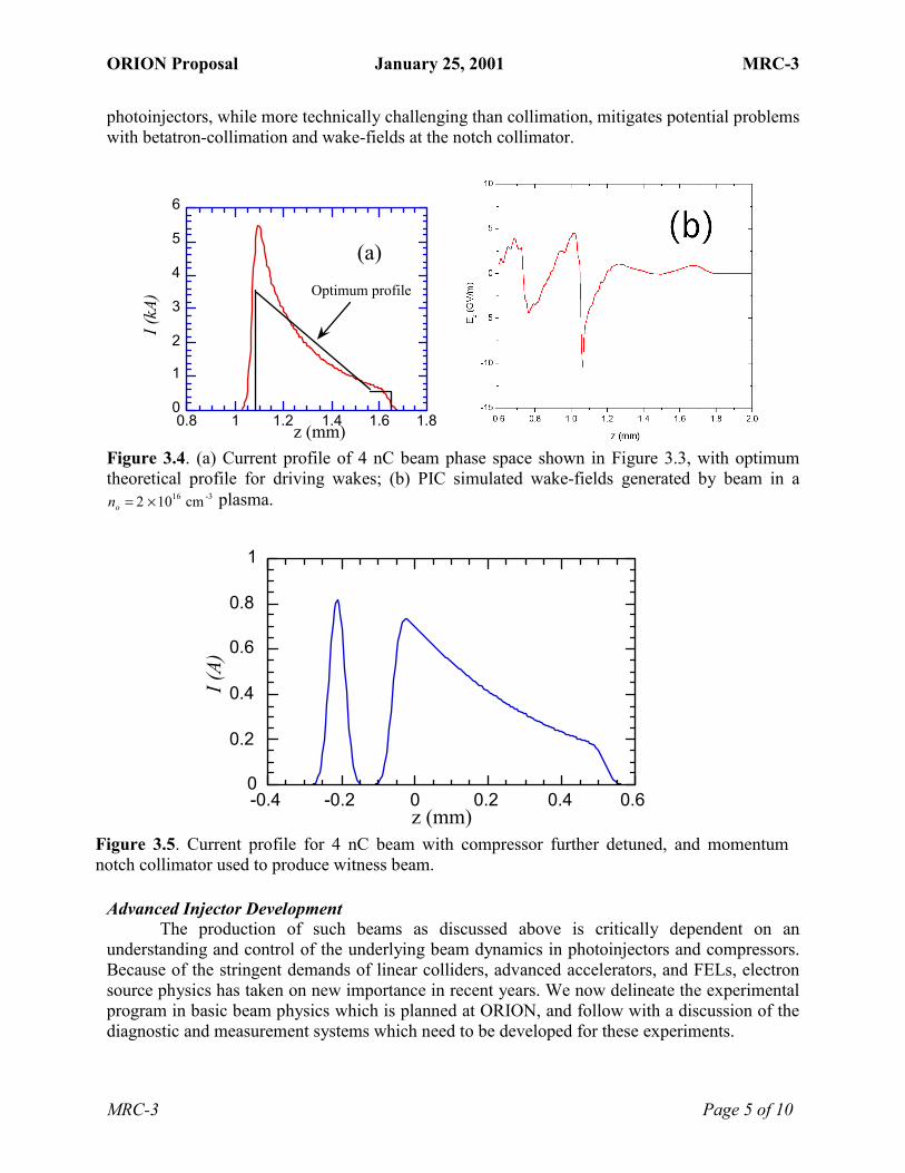
ORION Proposal January 25, 2001 MRC-3
MRC-3 Page 5 of 10
photoinjectors, while more technically challenging than collimation, mitigates potential problems with betatron-collimation and wake-fields at the notch collimator.
0
1
2
3
4
5
6
0.8 1 1.2 1.4 1.6 1.8
I (kA
)
z (mm)
(a)Optimum profile
Figure 3.4. (a) Current profile of 4 nC beam phase space shown in Figure 3.3, with optimum theoretical profile for driving wakes; (b) PIC simulated wake-fields generated by beam in a no = 2 ×1016 cm -3 plasma.
Advanced Injector Development
The production of such beams as discussed above is critically dependent on an understanding and control of the underlying beam dynamics in photoinjectors and compressors. Because of the stringent demands of linear colliders, advanced accelerators, and FELs, electron source physics has taken on new importance in recent years. We now delineate the experimental program in basic beam physics which is planned at ORION, and follow with a discussion of the diagnostic and measurement systems which need to be developed for these experiments.
0
0.2
0.4
0.6
0.8
1
-0.4 -0.2 0 0.2 0.4 0.6
I (A)
z (mm)
Figure 3.5. Current profile for 4 nC beam with compressor further detuned, and momentum notch collimator used to produce witness beam.

ORION Proposal January 25, 2001 MRC-3
MRC-3 Page 6 of 10
The space-charge dominated beam dynamics of photoinjectors has been described in terms of a scalable theory.8 This scaling of beam dimensions with charge to preserve emittance compensated performance, has not been experimentally verified. At ORION, we plan to do so, motivated in part by the fact that compression systems and wake-fields (plasma and otherwise) obey similar scaling laws.15,16 Thus we can tie one of the major concerns of MRC-5, that of the scaling of plasma wake-fields with respect to charge, in with the MRC-3 program. Technically, we are able to plan these experiments because of the pulse-length flexibility in the photocathode drive laser. The expected scaled performance of compression systems at ORION as a function of charge, and the impact of this scaling on parametric studies of plasma wakefield excitation, are discussed further in the section on MRC-5.
As the existing theory of emittance compensation is essentially based on viewing the beam as a cold plasma, the understanding of thermal effects, and their interplay with nonlinear-ities in the space-charge field, is not yet mature. The unfolding of these effects through ORION experiments is expected to play a prominent role during the commissioning of the injector.
Once the emittance compensation process has ended, the beam must then be compressed for many of the experiments listed in the PFC agenda. The collective effects which can significantly change the beam dynamics of compressing bunches are just now beginning to be measured at high brightness beam labs.17 Previously unexplored effects during compression arise from coherent synchrotron radiation (CSR) emission. When the beam electrons emit coherent radiation during bending, the electrons change energy, producing a dispersion mismatch at the end of the compressor. This phenomenon, along with other near-field forces termed non-inertial space charge cause beam quality degradation. A full exploration of these effects at ORION will entail measurement of the CSR spectrum, and correlating the emitted radiation properties to the induced energy spread and related emittance growth. As noted above, the double-bend, dispersion-free dogleg transport lines which deliver beam to the experimental halls have negative R56 Additionally, the chicane in the NLCTA beamline is nominally tuned for R56 = 0, and thus it will allow the positive and negative tuning of the total R56 about its nominal value set by the doglegs. As collective effects produce enhanced bunching with R56 < 0, the effects of CSR on the beam phase space are expected to be more pronounced in this case.
In order to avoid some of the deleterious effect of magnetic compression, it has been proposed that velocity based bunching be used on high brightness beam systems. This idea has additional resonance in the case of the ORION injector due to the need in some cases (e.g. high resolution laser acceleration experiments) to shorten the beam before acceleration in the linac, to avoid excessive energy spread by both inherent phase spread or, worse, the magnetic compression process. Two recent proposals for velocity based bunching will be evaluated for implementation at ORION: use of a buncher cavity before the first linac,18 and use of a non-speed of light linac structure for initial acceleration. In the second case, recently analyzed by L. Serafini (ORION collaborator from INFN-Milano), the beam undergoes one quarter of a synchrotron oscillation during capture in the "slow-wave" bucket.19 Bunching factors of nearly a factor of ten are reported from simulation studies.
In order to pursue the agenda of advanced beam source and basic beam physics studies, we must develop powerful beam diagnostics. It will not be possible to push the state-of-the-art in beam production and manipulation without this. In the area of transverse diagnostics, we will build upon expertise developed at both SLAC and UCLA. Because of beam fluctuations, it is important also to be able to make measurements on a shot-by-shot basis. For emittance measurements at ORION, this is problematic, because the slit-based phase space reconstruction

ORION Proposal January 25, 2001 MRC-3
MRC-3 Page 7 of 10
technique pioneered at UCLA20 is no longer feasible with the higher energies and lower geometrical emittances we expect. A single shot measurement based on transition radiation can be employed in this case,21 but it is a destructive technique. A single-shot nondestructive emittance diagnostic based on quadrupolar signals from beam position monitors will also be evaluated for possible implementation at ORION.22 In verifying the microscopic model of emittance compensation, it is necessary to unfold the slice (longitudinal position within the bunch) dependent behavior of the transverse phase space. In particular, we wish to examine not only the slice dependent orientation of phase space distributions, but also the contribution to the emittance by nonlinear effects within a slice (slice emittance). To do this, we plan to extend the time-resolved streak camera quad scan measurements recently developed at LANL to time-resolved tomography based on imaging information. In this regard, it should be noted that we will be utilizing expertise in both the UCLA, MRC-4 and MRC-5 members of the collaboration in use of streak camera and ultra-precise transverse beam profile measurements.
While the measurement of uncompressed beams at the ORION injector is handled well by the streak camera, magnetically and/or velocity bunched beams are beyond their experimental reach. The measurement of longitudinal beam structures at very short time scales is a severe challenge at ORION, as can be seen by the example of Figure 3.5, where important artifacts of distribution change in much less than a picosecond. At UCLA, two types of coherent radiation measurements of ultra-short bunch lengths have been employed. In the case of macrobunch (> 0.5 psec) measurements, a coherent transition radiation (CTR) interferometer technique was developed, and used with good success.23 This is a multi-shot autocorrelation measurement, however, and suffers from a long data taking time, and issues of signal reconstruction. In addition, a multi-shot (scanned monochromator) frequency domain CTR measurement of the microbunching of an electron beam (period of 13 microns) due to the SASE FEL process was shown to give insight into the beam microstructure.24 A variant of this technique, using a THz polychromator, has been developed by a Tokyo-Tohoku collaboration, shows great promise in measurement of < 500 fsec beams. UCLA has begun a collaborative effort with Tokyo-Tohoku to implement this technique at the Neptune Lab,25 and this effort will undoubtedly carry over into the ORION program.
While CTR (or CSR) based-schemes can give meaningful information in the sub-picosecond domain, they have an inherent ambiguity where it matters most to ORION � in the direct measurement of the time-domain structure, as opposed to frequency domain, or autocorrelation derived information. It has been recently proposed by X. Wang to use a dipole mode RF cavity to make direct beam structure measurements at fsec resolution in the LCLS case.26 This technique will be seriously evaluated, as it is the most promising from the viewpoint of measuring the beam structures exemplified by those in Figure 3.5. As one struggles with resolution due to large betatron beam size at lower energies (< 10 MeV), it is more robust at energies available in the ORION High Energy Hall.
Even though we have seen that the ORION injector complex in its initially envisioned configuration is a versatile and powerful experimental tool, further research and development in the areas of photoinjector physics and technology is planned. One of the most problematic topics in photoelectron production at present is the level and uniformity of the photocathode quantum efficiency (QE). At ORION we plan to address this issue with a program that extends the existing successful UCLA/SLAC collaboration on single-crystal Cu100 cathode development to other metals such as Mg100, which promise higher QE. We will also continue the development of

ORION Proposal January 25, 2001 MRC-3
MRC-3 Page 8 of 10
new cathode cleaning techniques, such as the DC e-beam-cleaning experiment now underway at Neptune.
In order to proceed to study more sophisticated cathodes, we will extend the col-laboration between UCLA and INFN-Milano on load-lock cathode systems appropriate for use in the 1.6 cell S-band gun and other S-band devices. This system is initially being designed for creation of high QE (1-10%) Cs2Te cathodes. With such a high QE, it would be possible to create pulse trains at ORION by splitting and delaying the laser pulse in a number of stages. It should also be noted that this technology would also open the door to possible study of other semiconductor cathodes in situ performance in high gradient RF photoinjectors.
Beam brightness scales as the inverse square of the RF wavelength because the acceleration fields are naturally higher and all of the beam dimensions are smaller.8 This is strong motivation to pursue higher frequency injector development, but there are several stumbling blocks. These include strong solenoids and reflected power from a standing wave photoinjector that must be handled without an isolator. The first issue can be addressed by use of a combined permanent magnet/current carrying solenoid. The second requires a fundamental change in RF design philosophy - the standing wave/travelling wave hybrid injector illustrated in Figure 3.6. In this device, the usual transient reflection of the standing wave portion of the structure is not present, as the travelling wave portion acts as a matched load. The beam dyn-amics in this new type of injector have undergone preliminary modeling using HOMDYN and PARMELA, and the RF design has begun. This project has drawn interest from industrial partners, and will be proposed as an SBIR funded collaboration with UCLA. Successful development of this device may eventually lead to an even higher brightness source for ORION.
One of the themes of this Physics Frontiers Center is that we may be forced to abandon RF based systems in order to progress in high energy accelerator development. This holds true as well for injection systems as well. Recent ideas for using plasmas as "cathodeless" electron sources have centered on use of lasers to induce local wave-breaking to inject background electrons into the plasma wave. Variations on this scheme, termed LILAC,27 are now under investigation at a number of laboratories. A new, simpler concept which uses only a density transition in a large amplitude plasma wakefield accelerator has been proposed and analyzed at UCLA28. This work, which will be conducted in collaboration with MRC-5, is discussed further in the MRC-5 section of this proposal.
π-mode standing wave section
π/2-mode travelling wave section
input coupling slotoutput coupling slot (to load)
Figure 3.6. Standing wave/travelling wave hybrid photoinjector concept.

ORION Proposal January 25, 2001 MRC-3
MRC-3 Page 9 of 10
Computer Modeling The experimental work of MRC-3, and indeed throughout the Center, is heavily
dependent on use of computer modeling to predict intense beam and plasma behavior. A number of codes are under continuous development by the Rosenzweig group and by L. Serafini and M. Ferrario who are collaborators in Italy. While these codes use a variety of approaches, from the quasi-electrostatic models of HOMDYN and UCLA PARMELA, to the fully self-consistent 2D particle-in-cell (PIC) code ITACA.29 While these efforts are some of the most ambitious in the field, they will be improved in this PFC by interaction with Mori's group in MRC-6.
In tandem with MRC-6, we hope to accomplish two important tasks. The first is to implement code input and output with a common data standard for describing beams. We are now looking at using the SDDS standard developed by M. Borland,30 which is presently used in LCLS design work for passing particle distributions from UCLA PARMELA to ELEGANT,31 and to the 3D FEL code GENESIS. This standard will allow us to more efficiently develop "end-to-end" simulations, where we begin with electrons at the photocathode, and follow them through the injector, through manipulations such as the compressor and, finally, simulate the physics of an ORION experiment.
The second goal of MRC-3/MRC-6 collaboration is the introduction of the parallelization and 3D PIC techniques, which have been developed to a sophisticated level by plasma modelers, into basic beam physics modeling. While 2D simulations provide a partial model of the relevant beam, plasma and radiation effects of concern to MRC-3, they are quite slow, due to the spatial and temporal resolution required. The expertise of MRC-6 will be used to parallelize ITACA, to bring it to full potential for exploring electron beam physics. In addition, even detailed 2D simulations are not complete. Use of 3D PIC modeling can give insight into such fundamental phenomena as three-dimensional space-charge, non-inertial space-charge, CSR, CTR, and the FEL instability. It is necessary to understand many of these effects, using the most powerful computational tools available, in order to optimize the experimental approach of this MRC. 1 D. T. Palmer, �The next generation photoinjector�, PhD. Thesis, Stanford University, 1998. 2 M. Babzien et al, Phys. Rev. Lett. 76, 3723 (1996). 3 J.B. Rosenzweig et al, Nucl. Instr. Meth. A, 410, (1998). 4 J.F. Schmerge et al, �Photocathode rf gun emittance measurements using variable length laser pulses,� SPIE 3614 (1999) 22. 5 G. Travish et al, "High-Brightness Beams from a Light Source Injector: The Advanced Photon Source Low-Energy Undulator Test Line LINAC", Proc. XX Linac Conference (2000). 6 M. Ferrario et al, Proc. ICFA Advanced Accelerator Workshop on the Physics of High Brightness Beams, Los Angeles, (2000). 7 L. Serafini and J.B. Rosenzweig, �Envelope analysis of intense relativistic quasilaminar beams in rf photoinjectors: A theory of emittance compensation,� Phys. Rev. E 55 (1997) 7565. 8 J.B. Rosenzweig and E. Colby, "Charge and Wavelength Scaling of RF Photoinjector Designs", Advanced Accelerator Concepts p. 724 (AIP Conf. Proc. 335, 1995). 9 L. Young et al, PARMELA ver 3, LA-UR-96-1835, Revised December 4, 2000. 10 K. J. Kim, Nucl. Instrum. Methods Phys. Res., Sect. A 275, 201 (1989). 11 S. G. Anderson, J. B. Rosenzweig, "Nonequilibrium transverse motion and emittance growth in ultrarelativistic space-charge dominated beams" Phys.Rev.ST Accel. Beams 3, 094201 (2000). 12 T. Katsouleas, Phys. Rev. A 33, 2056�2064 (1986)

ORION Proposal January 25, 2001 MRC-3
MRC-3 Page 10 of 10
13 J. B. Rosenzweig, B. Breizman, T. Katsouleas, and J. J. Su, "Acceleration and focusing of electrons in two-dimensional nonlinear plasma wake fields", Phys. Rev. A 44, R6189 (1991). 14 N. Barov et al, "Observation of plasma wakefield acceleration in the underdense regime", Phys. Rev. ST Accel. Beams 3, 011301 (2000). 15 J.B. Rosenzweig, N. Barov and E. Colby, "Pulse Compression of RF Photoinjector Beams: Advanced Accelerator Applications", IEEE Trans. Plasma Sci. 24, 409 (1996). 16 J. Rosenzweig et al, "Towards a Plasma Wake-field Acceleration-based Linear Collider", Nuclear Instruments and Methods A 410 532 (1998). 17 H. H. Braun et al, "Emittance growth and energy loss due to coherent synchrotron radiation in a bunch compressor", Phys. Rev. ST Accel. Beams 3, 124402 (2000). 18 G. Travish, private communication. 19 L. Serafini and M. Ferrario, to appear in Proc. ICFA Workshop on Physics and Applications of X-ray SASE FEL, Arcidosso (2001). 20 S. Hartman et al,"Initial Measurements of the UCLA RF Photoinjector" Nucl. Instr. Methods A 340, 219 (1994). 21 G. Lesage, et al, "Transverse phase space mapping of relativistic electron beams using optical transition radiation Phys. Rev. ST Accel. Beams 2, 122802 (1999). 22 Roger H. Miller et al,."Nonintercepting beam monitor", in Proc.12th Int. Conf. on High Energy Accelerators, Batavia, IL (1983). 23 A. Murokh et al, "Bunch length measurement of picosecond electron beam from a photoinjector using coherent transition radiation" Nucl. Instr. Methods A 410, 549 (1998). 24 A. Tremaine et al "Observation of Self-Amplified Spontaneous Emission-induced Electron Beam Microbunching Using Coherent Transition Radiation", Phys. Rev. Lett., 81 5816 (1998). 25 M. Uesaka et al, to appear in Proc. ICFA Workshop on Physics and Applications of X-ray SASE FEL, Arcidosso (2001). 26 X.Wang, "Producing and measuring short bunches", Proc. 1999 Part. Accel. Conf., 2018 (2000). 27 D. Umstadter, J. K. Kim, and E. Dodd, �Laser Injection of Ultrashort Electron Pulses into Wakefield Plasma Waves�, Phys. Rev. Lett., 76, 2073(1996). 28 H. Suk, N. Barov, J.B. Rosenzweig and E. Esarey, " Plasma Electron Trapping and Acceleration in a Plasma Wake Field Using a Density Transition", to be published in PRL. 29 L.Serafini, C.Pagani, Proc. 1st EPAC, Rome, June 1988, Ed. World Sci., p.866 30 M. Borland, "Doing Accelerator Physics Using SDDS, UNIX, and EPICS", Proc. International Conf. on Accelerator and Large Experimental Physics Control Systems, 382-391 (1995). 31 M. Borland, "elegant: A Flexible SDDS-Compliant Code for Accelerator Simulation", ANL Light Source Note LS-287, 08/2000.

ORION Proposal January 25, 2001 MRC-4
MRC-4 Page 1 of 7
Major Research Component 4 - Laser Acceleration Personnel: Prof. Robert Byer of the Stanford Applied Physics Department will be the PI responsible for this MRC. Prof. Robert Siemann of SLAC and the Stanford Applied Physics Department will be an active participant in laser acceleration research. Senior staff will include Roger Route, a Stanford Senior Research Engineer, James Spencer, a SLAC Research Physicist, and Eric Colby who is a W. K. H. Panofsky Fellow at SLAC. Two postdoctoral researchers, four graduate students, and one or two undergraduates will be involved. Prof. Levi Schächter of the Technion Electrical Engineering Department will be a collaborator, and he will have one or two students working on these experiments or providing theoretical support.
Motivation
Demands of high-energy physics are such that achieving the highest possible energy gain in a given distance is of paramount importance if a linear collider is to be economically feasible. This in turn requires coherent radiation sources capable of very high peak power for short pulses, traditionally a role played by klystrons in microwave accelerators. Lasers possess two advantages over microwave tubes as power sources for a linear collider, namely: (1) considerably higher peak powers are possible (10 GW at 0.8 micron from commercially available Ti:Sapphire lasers versus 75 MW at 11.4 GHz from the SLAC X-band klystron) and (2) significant industry interest in developing higher power laser sources and power handling devices at a time when industry interest in vacuum power tubes is declining.
The extraordinary growth in use of the Internet has driven the telecommunications industry to what analysts predict will this year be a trillion-dollar-a-year market. Explosive growth of fiber optic networks for long-haul data transmission is driving the development of inexpensive lasers and associated technologies, including lithographically produced optical components. As an example, phase locking of two separate mode-locked femtosecond lasers has been recently accomplished,1 and is being actively pursued at NIST in efforts to develop an optical frequency comb for use as a measurement standard.2 This represents a critical step toward powering multiple accelerator structures. Developing acceleration methods that will capitalize on inexpensive power sources and components is therefore very attractive economically, and is rapidly becoming feasible technically.
The key difficulty in developing accelerator technologies suited to laser sources derives from the short wavelengths at which the most efficient, commercially viable lasers operate. Traditional metallic accelerating structures composed of disk-loaded circular waveguides operated in the lowest passband simply become too difficult to fabricate at optical wavelengths due to prohibitively tight tolerances, and they would not survive the intense surface heating when powered. Consequently, new concepts capable of efficiently coupling coherent radiation to a passing particle beam must be sought out and tested. Introduction
Laser acceleration experiments share the need for a powerful drive laser and specialized diagnostics for probing the properties of the very low-charge, low-emittance beams required. These will be developed and available at the Center, making it possible to perform a wide range of sophisticated laser acceleration experiments.
For each of the following research projects, the experimental setup is quite similar. A medium energy electron beam (50-350 MeV) will be produced in an RF photoinjector and linac, focused to a spot size of some tens of microns and passed through the test accelerator. A high resolution charged particle beam spectrometer, located immediately downstream of the test

ORION Proposal January 25, 2001 MRC-4
MRC-4 Page 2 of 7
accelerator, will be the primary diagnostic for understanding the electron beam interaction with the test accelerator. Profile monitors and timing monitors will also be required to establish that synchronism and alignment conditions will be met. The primary instrumentation challenge for laser acceleration experiments arises from the very small dimensions of the accelerator structures which in turn require electron bunches with: (1) very low charge (typically 5-10 pC), (2) short temporal extent (less than 2 ps), and (3) good quality (typically under 10-5 m normalized emittance, and less than 10-20 keV energy spread). Instruments capable of diagnosing these low charge bunches require additional development effort and in some cases different detection methods altogether than are used for the higher charge beams discussed elsewhere in this proposal.
Laser acceleration experiments also require a versatile, well-diagnosed laser system to power the test structures. The laser pulses must be precisely synchronized (to better than a picosecond) to the electron beam. The development of such a laser system, which must be carefully linked to the photocathode drive laser, represents a substantial infrastructure investment and for many laser acceleration experiments, the dominant cost element.
The laser system, high sensitivity diagnostics, and experience in manipulating low charge beams will form a shared resource that a broad range of laser acceleration experiments can effectively capitalize on. Experimentalists can focus substantially more of their efforts on the details of their own experiment with many of the ancillary components needed to integrate the experiment into the ORION accelerator having already been developed. Laser Electron Acceleration Project
The Laser Electron Acceleration Project (LEAP)3,4,5 is an experiment to accelerate electrons in the fields of two crossed Gaussian laser beams. Profs. Robert Byer and Robert Siemann conceived and have led the experiment from inception to the present and will continue to lead it at ORION. James Spencer and Eric Colby have provided and will continue to provide support for beam optics and diagnosis, experimental design, data collection and analysis, and accelerator operation. Professor Levi Schächter and a graduate student of his have supported and will continue to support the experiment with detailed theoretical calculations of wakefield and interaction effects. Two postdoctoral associates will participate, and at least two graduate students will perform their dissertation research on this project, with each phase of the LEAP experiment envisioned to be roughly the work of a single dissertation.
Measurements to verify the dependence of the strength of the interaction on the laser pulse length, interaction length, laser divergence at the focus, relative phase of the two Gaussian laser pulses (shown in Figure 4.1 below), and polarization of the pulses will form the core of the initial physics program. Operating at half the damage fluence for the fused silica optics used, the expected energy gain from a length-optimized interaction cell is ±334 keV, implying an average accelerating gradient of over 0.3 GeV/m. Examination of engineering questions that impact the viability of this method for large-scale development, such as stability of the acceleration with respect to dimensional and timing errors, and modal purity of the laser mode used for acceleration will also be addressed. This first phase was initiated in 1997 and was initially funded from Stanford University patent income and later joined by money from DOE/HEP. Constructed at the Hansen Experimental Physics Laboratory (HEPL) on the Stanford campus, this phase of the experiment has suffered from poor beam quality and very limited beam time from the superconducting accelerator. It is expected that this phase will reach completion by April of 2002, at which time a natural transition to the ORION facility can take place.

ORION Proposal January 25, 2001 MRC-4
MRC-4 Page 3 of 7
The second phase of the LEAP experiment will involve staging two successive laser accelerators. Two interaction cells will be used in succession, with the first serving to optically bunch the low-energy (50 MeV) electron beam, and the second, suitably phased, serving to accelerate it. This experiment will demonstrate two essential points: first, that an optical pulse train can be made in a straightforward manner by optically bunching a conventionally-produced beam, and second, that phase coherence between two accelerator sections a macroscopic distance apart can be maintained at the attosecond (10-18 s) scale. This has been demonstrated at an order of magnitude longer timescale, using inverse free electron lasers and a 10 micron laser by Kimura et al6. We seek to demonstrate this at 1 micron. As difficult as the first phase of the LEAP project is, the greater difficulty of the second phase will require beam of significantly greater stability and availability. Conducting the second phase at an accelerator test facility specifically engineered for the purpose and at which beam time is available in short, frequent increments will have significant impact on the progress of this critical phase.
The third phase of LEAP will be to examine large-scale inexpensive fabrication methods for making the structures. Any reasonable energy accelerator built from laser acceleration cells will have to combine many cells for increased energy gain and power efficiency. It is therefore important to develop methods for fabricating the high precision surfaces that form the accelerator cells. Fortunately, integrated circuit development has progressed to such an extent that highly complex, highly precise structures can be fabricated very inexpensively in a variety of materials by lithographic techniques. This phase will involve fabricating and testing multi-cell accelerator structures from quartz or silicon using lithographic techniques and then testing these structures with high power lasers and ultimately with electron beam. Physics issues of laser mode shaping
Figure 4.1: The LEAP acceleration cell geometry (left) and computed field intensity both inside and downstream of the accelerating cell (right) are shown.

ORION Proposal January 25, 2001 MRC-4
MRC-4 Page 4 of 7
and preservation through many optical elements as well as focusing and preserving an electron beam through the many small structure openings will have to be addressed. Material science issues relating to structure damage from the laser and electron beams will also be addressed. Development of lasers suitable for powering microstructures made from silicon or quartz is a research area that not only lies at the edge of present telecommunications research, but is specifically included in this years DOE SBIR solicitation. Professor Byer�s group plans to aggressively pursue an industrial partner to develop efficient lasers operating in the 1.6-2.5 micron range.
With optoelectronic technology advancing rapidly, producing the drive lasers, optical transport elements, focusing elements, and accelerator structures on a single substrate by lithography alone is becoming a very real possibility. The result would be an integrated accelerator that is more self-contained, inexpensive, and broadly usable than any vacuum tube based accelerator today. Propitiously, strong market forces are driving virtually every aspect of the required research. Amplified Cherenkov Wakefield Accelerator
The second major laser acceleration experiment planned for ORION is to experimentally demonstrate an entirely new mechanism for acceleration: wakefield amplification in an active medium. Professor Levi Schächter of Technion IIT, Israel, has proposed7 that the Cherenkov wakefield generated by a charged particle moving close to a dielectric can be amplified if the atoms of the dielectric medium can be placed in an excited state (for example with a flashlamp) at the time the electron bunch passes. Modern laser systems make frequent use of an analogous process: an oscillator laser produces low energy photon pulses whose passage through a subsequent laser amplifier triggers the release of photons which are in phase with the trigger pulse and add coherently to its field. In this case, however, the virtual photons associated with the space-charge field of a �trigger� electron bunch provide the stimulus for release of energy from the amplifier medium. The amplitude of the wakefield grows exponentially behind the trigger electron bunch, and at some point saturates when the absorption and stimulated emission processes are in equilibrium. At this location a large amplitude wakefield is expected, and a suitably timed �witness� electron bunch will experience strong accelerating fields, in excess of 1 GeV/m for Nd:YAG or Ti: Sapphire8. This mechanism for charged particle acceleration is entirely new and enjoys the distinct advantage over more conventional schemes that the power source and accelerator structure are one, eliminating power transmission losses and providing some unique capabilities, to be discussed below.
The first phase of the experiment will be to demonstrate Cherenkov radiation amplification in an active medium. Professor Robert Siemann and Dr. Eric Colby will collaborate closely with Professor Levi Schächter to design the beam optics, diagnostics, and accelerator itself. This initial phase is expected to become the thesis subject of a graduate student.
The evanescent nature of the beam space charge fields implies that the Cherenkov wakefield induced in the active medium will decrease exponentially with distance away from the medium. The characteristic damping distance is inversely proportional to beam energy, so that higher energy beams induce larger Cherenkov wakefields. Consequently, the higher energy (350 MeV) beam planned at the ORION facility will be propagated through a small hole in an annular laser medium, (e.g. Nd:YAG or Ti:Sapphire) which has been suitably pumped to produce a population inversion, and designed to guide the Cherenkov radiation. In the absence of the bunch, amplified spontaneous emission (ASE) is expected in equal amount at both ends of

ORION Proposal January 25, 2001 MRC-4
MRC-4 Page 5 of 7
the active medium. When the bunch is injected, this symmetry is broken and Cherenkov radiation is emitted by the bunch and further amplified by the medium in the direction of the bunch velocity. A 3 nC electron bunch of 75 micron radius traversing a Nd:YAG rod with a 1 mm hole will produce 2 µW of Cerenkov radiation, which calculations show will amplify to become a 3 MW pulse in a saturated medium. The amplified spontaneous emission from each end of the medium is expected to be an order of magnitude9 less than the pump power, or on the order of 10 kW. Therefore, ignoring reflections from both ends, the difference between the number of photons at both ends of the slab is directly related to the amplified Cherenkov radiation. Based on this result the second phase of the experiment will begin.
The second phase will use a mode-selecting geometry, depicted in figure 4.2, to produce amplified Cherenkov fields in the beam hole suitable for accelerating high-quality electron beams. A planar geometry for the active medium and enclosing high reflector is envisioned for this phase. The planar geometry permits the use of a multi-layer frequency-selective reflector on the outside of the active medium permitting unwanted higher order modes to escape, improving beam quality. Additionally, the experiment will be performed with two electron bunches, the first acting as the �trigger�, and the second bunch being deployed behind the first (as a �witness� bunch) at a varying distance to directly measure the exponentially growing wakefield strength. Charged particle beam spectrometry of the witness pulse will form the primary diagnostic for this measurement. Measurement of the acceleration and transverse effects on the witness pulse will allow detailed diagnosis of the quality of the wakefield for acceleration. SBIR funding and an industrial participant are being sought for the design and manufacture of the pumped laser media for both phases of the experiment. The design of the first phase draws heavily on existing laser amplifier design, but with the added optical complication of a hollow gain media. The second phase explores the assembly of gain media into novel, mode-selecting optical resonators and as such represents basic laser research. Summary
With the founding of a versatile physics center having beam quality and diagnostic capabilities well suited to conducting laser accelerator physics experiments comes the possibility to examine many other proposed laser acceleration schemes. Examples include the examination of a photonic band gap fiber accelerator10, which exploits the nearly higher-order mode-free properties of photonic band gap structures in an easy-to-fabricate structure made from materials
Figure 4.2: Active medium accelerator cell geometry, showing the mode-selecting multilayer dielectric mirrors and active medium.

ORION Proposal January 25, 2001 MRC-4
MRC-4 Page 6 of 7
and techniques in wide use in the telecommunications industry today. Overmoded, oversized circular waveguides11 have long been proposed as guides for optical modes with desirable field properties for particle acceleration, but have yet to be experimentally demonstrated. Extension of the LEAP experiment to examine the benefits of using higher order laser modes to provide simultaneous acceleration and focusing can also be explored.
Beyond high-energy physics, the development of the laser accelerator will drive other applications. A laser accelerator will produce extremely short electron bunches (less than 10 attoseconds) which opens the possibility of performing pump/probe experiments at the attosecond time scale. Furthermore, the attosecond-bunched electrons can be used to pump a free electron laser (FEL) that would operate in the hard X-ray wavelength region. These electron pulses allow the FEL radiation to grow by Self Amplification of Stimulated Emission (SASE) in a single pass12. This presents the possibility of a laboratory-scale laser accelerator followed by an FEL that generates coherent X-rays of unprecedented brightness and coherence.
Both the LEAP experiment and the Cherenkov wakefield amplification experiments draw heavily on technical knowledge of lasers and associated diagnostics and the manufacture of optical devices, both of which are key to the rapidly developing telecommunications industry. The doctoral students who perform research in these topics will acquire skills and knowledge that will be valuable in developing the next generation of technologies for communications. Lithographic fabrication of the LEAP laser acceleration structures will borrow directly from the vast expertise in the Silicon Valley and applying it to an entirely new endeavor, the development of silicon or quartz microstructures which can perform highly specific laser mode shaping at high powers, a capability with potential applications in optical computing and adaptive optics. Development of these acceleration methods not only will establish at least two novel physical mechanisms of electron acceleration but will also potentially make possible the construction of the next generation of high energy physics machines. 1 M. Bellini, T. Hänsch, �Phase-locked white-light continuum pulses: toward a universal optical frequency-comb synthesizer�, Opt. Lett. 25, 1049 (2000). 2 Diddams et al, �Direct link between Microwave and Optical Frequencies with a 300 THz Femtosecond Laser Comb�, Phys. Rev. Lett., 84 (22) 5102, (2000). 3 Y.C. Huang, D. Zheng, W. Tulloch, R.L. Byer, �Proposed structure for a crossed-laser beam, GeV per meter gradient, vacuum electron linear accelerator�, Applied Physics Letters 68, p. 753 (1996). 4 Y.C. Huang, R. L. Byer, �A proposed high-gradient laser-driven electron accelerator using crossed cylindrical laser focusing�, Applied Physics Letters 69, p.2175 (1996). 5 R. Byer et al, �The Laser-Driven Electron Accelerator Experiment at Stanford University�, in Proc. IEEE Particle Accelerator Conference, New York, NY, p321-324, (1999). 6 Kimura, W et al, �Demonstration of a Laser-Driven Prebuncher Staged with a Laser Accelerator�The Stella Program�, in Proc. Adv. Accel. Conf., Santa Fe, NM, June (2000). 7 L. Schächter; Physical Review Letters 83, p.92 (1999). 8 L. Schächter et al, �Wake-Amplification by a Solid State Active Medium�, in Proc. Advanced Acceleration Concepts Conference, Santa Fe, NM, (2000). 9 W. Koechner, �Solid-State Laser Engineering�, 3rd Ed., Springer-Verlag, Berlin, p. 182, (1992). 10 X. Lin, �Photonic Band Gap Fiber Accelerator�, SLAC-PUB-8633, submitted to Physical Review Letters (2000).

ORION Proposal January 25, 2001 MRC-4
MRC-4 Page 7 of 7
11 N. Kroll, �General Features of the Accelerating Modes of Open Structures�, in AIP Conf. Proc. V. 130, p.253ff, (1985). 12 Y. C. Huang, R. L. Byer, �Ultra-Compact, High-Gain, High-Power Free Electron Lasers Pumped by Future Laser-Driven Accelerators�, in Free Electron Lasers, G. Dattoli and A. Reneiri, eds., (Elsevier Science B, v. 1), pp II-37ff, (1997).

ORION Proposal January 25, 2001 MRC-5
MRC-5 Page 1 of 9
Major Research Component 5 � Plasma-Beam Physics Personnel: Professors Chandrashekar Joshi of the UCLA Electrical Engineering Department and Thomas Katsouleas of USC will be co-PI�s who will provide the overall leadership for this MRC. Dr. Christopher Clayton is a senior research physicist, and Dr. Kenneth Marsh is a staff engineer in Prof. Joshi�s group, which also has a postdoctoral associate and six graduate students. Additional personnel working on this MRC include Profs. Warren Mori and James Rosenzweig, and Dr. Chris Clayton from UCLA, Dr. Patrick Muggli of USC, and Prof. Robert Siemann, Dr. Robert Noble, Dr. Mark Hogan, as well as 1 postdoctoral fellow and two graduate students from SLAC.
This MRC addresses key issues for realizing novel concepts based on plasma
acceleration, focusing and radiation production via the interaction of relativistic electrons with self-induced electromagnetic fields in a plasma. Many ideas for accelerating, focusing and generating radiation have been proposed using the relativistic electron beam-plasma system. These have yet to be realized in systems or components that are mature enough to be part of an operating accelerator. MRC-5 proposes to explore some of the key physics issues necessary for their realization. It also extends the work on plasma-based concepts begun in MRC-1 in the FFTB. The research exploits the flexibility offered by ORION: variable bunch length, witness/trailing bunches, variable currents and beam densities, and low emittance.
Table 5.1 shows a list of some of the ideas that can be explored at ORION. These are subdivided into four categories: acceleration, focusing/steering, radiation production, and basic science. The most effective approach to bringing these ideas to fruition involves experimentation
Table 5.1: Electron Beam�Plasma Interaction Experiments Experiment Physics
Acceleration High Transformer PWFA Chicane optimized drive bunch shape gives large wake amplitudes
(> GeV/m). Witness bunch maps amplitude. Focusing/Steering Hi Demagnification Plasma Lens
400µm to 4µm spot with M=1/100 to test geometric and chromatic aberrations.
Steering & Slicing at a Gas-Plasma Interface
Deflected e-beam. Fast switching via laser plasma. Energy modulation on intra-bunch timescale + bend = slicer
Laser Guiding
Laser Guided over 100 Rayleigh Lengths. Extended interaction for Laser Wakefield Accelerator.
Radiation Production Ion Channel Laser (ICL) Short plasma cell replaces a long undulator magnet in an FEL.
Could be demonstrated in visible (50 MeV beam) and ultraviolet (300 MeV)
Basic Physics Electron Hose Instability Parametric study of the onset and saturation. Blowup of beam. Beam Loading Adjust charge and delay of witness bunch to beam load the plasma
wake and minimize energy spread of accelerated particles. Self-trapping Sharp downward transition in plasma density traps plasma electrons
in accelerating wake for �injector-less� accelerator.

ORION Proposal January 25, 2001 MRC-5
MRC-5 Page 2 of 9
performed in concert with theory and advanced numerical simulation. Having a stable and well diagnosed electron beam is critical for these experiments, and a long-term investment in instrumentation and operational techniques, possible only with a center is crucial. We discuss one experiment from each of these categories in some detail below and make brief comments on other ideas listed in Table 5.1. Acceleration
By replacing the metallic walls of conventional structures with �plasma-walls� many limitations are avoided and very high gradients can be achieved. The experiments proposed here will assess the viability and limitations of electron beam-driven plasma wakefield accelerators (PWFA�s). By capitalizing on resources unique to the PFC such as long, high-density plasma sources suitable for PWFA, and utilizing the magnetic chicane to manipulate the drive bunch length and distribution (see MRC-3), we will be able to explore some of the most important phenomena in PWFA. Specifically, we can measure the transformer ratio (the ratio of accelerating field after the bunch to the decelerating field within the bunch), transverse focusing fields, and the dependence of the gradient on plasma density, bunch length, beam and plasma radius.
High Transformer Ratio Plasma Wakefield Acceleration. This experiment is primarily a study of the dependence of the PWFA transformer ratio on bunch shape. The optimization of the transformer ratio is accomplished by using ramped beams in a dense plasma with the pulse length much greater than the plasma wavelength. The first critical experimental issue is shaping the bunch, and as seen in MRC-3, the use of negative R56 in the magnetic chicane can provide electron beam drivers with longitudinal profiles suitable for maximizing the accelerating wake � a current distribution with a ramped rise and a very sharp fall. Such a distribution is nearly ideal for driving wakefields with a high transformer ratio. The experimental demonstration of this effect is a focus of this MRC.
The two-bunch configuration (discussed in MRC-3) with a driving bunch and separate trailing bunch is required for this experiment. The slightly delayed �witness� pulse can probe the accelerating wakefields downstream of the ramped drive bunch. Specifically, the leading electron bunch enters the plasma, and due to nearly linear increase or ramp in beam density, adiabatically expels the plasma electrons, with an induced electric field that is relatively small. Half a plasma period later the plasma electrons rush back in behind the drive bunch to form a large density spike on axis (Figure 3.4). This spike creates a large amplitude electric field that accelerates the trailing or witness bunch. This scheme offers several advantages over single bunch experiments, in that the accelerating wake is determined entirely by the drive bunch. Changing the relative delay of the witness distribution can then be used to map out the accelerating wake behind the drive beam.
To perform such an experiment, one must not only prepare a beam with slow ramp and fast fall times, but also provide matching optics so that the beam can be injected with the appropriate transverse equilibrium in the ion-rich plasma channel.1,2,3 For a plasma density n0 = 2 ×1016 cm−3 , this implies a very short depth of focus of 2.1 mm at 350 MeV. Thus the likely site for this experiment is the ORION High Energy Hall. This choice is also wise from the related standpoint of beam density (nb), which we would like to be larger than the plasma density. Using a conservative normalized emittance of 8 mm-mrad to account for dilution during transport and compression, the ratio nb/n0 = 3.6 at 350 MeV, and it scales with energy as γ½. Again we find that the higher energy is favored.

ORION Proposal January 25, 2001 MRC-5
MRC-5 Page 3 of 9
Another critical experimental issue involves creating uniform plasmas with densities greater than 1016 e-/cm3. Professor Joshi�s group has a history of successful development of plasma sources for PWFA. Photo-ionized lithium plasmas have been developed with lengths of up to 1.4 meters and densities up to 1015 e-/cm3 for SLAC experiments E-157 and E-162. The low atomic number of Li (and correspondingly low impact ionization cross section), variable density, and low accoustic noise of such plasmas are well suited for PWFA. To achieve the high density plasmas called for here, we will use a photo-pumping scheme4 that fully ionizes the Lithium vapor in a two-stage process. Although the plasma densities required for this experiment are higher than in the existing E-157/E-162 sources, the length required is relatively short, as the beam is predicted to lose most of its energy (at nearly a 1 GeV/m deceleration rate) within 40 cm of propagation.
While the optimization of the plasma wake-field accelerator transformer ratio is accomplished by using ramped beams in a dense plasma, the wake amplitude is optimized by shock exciting the system using a beam with an rms length roughly three times the plasma wavelength. In this case one obtains a transformer ratio less than two, but a higher accelerating field behind the beam. It has been noted that from linear plasma wake-field theory, and computational investigations of nonlinear wake-fields,5,6 the scaling of beam energy loss rate with pulse length follows that of coherent Cherenkov radiation in a high impedance environment, approximately
2 21decel. 2 2b p b zE eN k eN σ −≅ ≅
where Nb is the number of beam particles, kp is the plasma wavenumber, and σz is the rms bunch length. This relation indicates two things: that the pulse length should be made smaller, and further, that a short pulse should be injected into a dense plasma. This scaling has been noted, and proposed to lead to a compact design for the "Afterburner" plasma wake-field accelerator.6 The effect of shortening the beam at constant charge has been observed dramatically in compressed beam UCLA/FNAL PWFA experiments in the FNAL A0 lab, where a portion of a 4 nC, 15 MeV beam has been decelerated nearly completely in less than 9 cm plasma.7 To make the beam shorter, as seen in MRC-3, we intend to compress the beam after it is accelerated in the photoinjector, using the linac phase choice, and tunability of R56 in the chicane as well as the transport system to the experimental halls. At the most extreme case of bunch compression, the predicted wake amplitude approaches 100 GeV/m.
This set of experiments is challenging from the point of view of beam compression, witness beam generation (difficult near optimum compression) and transverse matching. It is also very demanding on the flexibility of the plasma sources that need to be produced. The wide range of beam properties encountered in this important study also provides great challenges for beam diagnosis. Finally, much of the physics is intractable with strictly analytic techniques and numerical models are needed. Such next generation experiments are critical to address the viability and limitations of PWFA and how such devices might one day be employed for concepts like the Plasma Afterburner discussed in MRC-1. Focusing & Steering
The length of conventional final focus systems of known high-energy collider designs increases proportional to the beam energy raised to either the 2 or 3/2 power8. Further, the length is mainly determined by the natural chromaticity that depends on both the strength of the final quads and their proximity to the Interaction Point. For future colliders this can lead to a final focus system that is many kilometers long. Strong lenses very close to the Interaction Point would allow a significant reduction of the system length.8

ORION Proposal January 25, 2001 MRC-5
MRC-5 Page 4 of 9
Plasma focusing devices are compact, simple and very strong focusing elements. Focusing gradients in excess of a MT/m are possible. Recent plasma lens experiments have demonstrated plasma focusing of both 30 GeV electron and positron beams.9,10 Despite the large focusing strength demonstrated in these previous experiments, there has yet to be an experimental demonstration of high demagnification of beam size (i.e. > 4) with a plasma lens. In this MRC we propose to test the limits to spot size reduction in a high demagnification plasma lens. Such a lens, if achievable, would overcome many of the limitations of conventional quadrupole focusing. High Demagnification Plasma Lens. There are three limitations to the demagnification that can be achieved with a plasma lens: beam emittance, geometric aberrations, and chromatic aberrations,11 and these effects need to be investigated. For a plasma lens with a focal length equal to the length of the plasma, the demagnification is proportional to the beam energy, the square of the beam size at the lens, and inversely proportional to the normalized emittance. One caveat to the large initial beam size is that the initial size must be small enough such that the initial beam density is much greater than the plasma density to achieve full expulsion of the plasma electrons. For a 350 MeV beam, a 400 µm initial spot and an invariant emittance of 8 mm-mrad, the demagnification is approximately 50. The plasma would be 15 cm long, the density n0=1012 cm-3 and the focal length about 30 cm.
Geometric aberrations arise from non-uniformities in the plasma/ion density and motion of the ions due to the space charge electric field of the beam. This serves to set bounds for the initial beam size. If the beam density is too low the majority, if not all, of the beam will not see a preformed ion channel and will experience a time dependent focusing force. If the beam density is too high, the space charge electric field may be large enough the move the plasma ions on the timescale of the passage of the electron bunch, again giving rise to a time dependent focusing along the bunch. Non-uniformities in the ionization laser can produce transverse density gradients in the plasma. For a 400µm spot size we might expect these values to be on the order of 1%, in which case this will limit the demagnification to 200 for the parameters above. As an experimental check, a wedge in the path of the ionization laser could create a transverse density gradient of 10%. That would limit the demagnification to 20 thereby increasing this deleterious effect from a negligible to a dominant one.
Chromatic aberrations limit the demagnification due to the fractional energy spread of the beam. For the parameters above and the energy spread of 0.8% shown in Figure 3.4, the limit would be ~125, making this important but not dominant. Effects such as the longitudinal wakefield in the plasma lens may increase the energy spread and make chromatic aberrations more important. This induced energy spread is an important factor we must consider in the design of this experiment at ORION.
A high demagnification plasma lens experiment would systematically study the focused spot size as a function of initial beam size, plasma density-length product, plasma uniformity, and energy spread. Experiments thus far have involved sampling techniques that average over many shots. High resolution, single-shot OTR, which has been developed for E-157 and MRC-1, and deployed in previous plasma focusing experiments involving UCLA elsewhere3,9, is critical to distinguish the effects of the plasma lens from fluctuations in the electron beam.
Steering and Slicing of Electron Beams Using Plasma Gas Interfaces. It has been observed in E-157 that during alignment procedures the electron beam tends to follow the laser beam used to create the plasma due to a type of off-axis plasma lensing. This simple demonstration intimates the possibility of powerful new tools for manipulating beams, including magnet-less

ORION Proposal January 25, 2001 MRC-5
MRC-5 Page 5 of 9
kickers and beam slicers that could turn on and off on unprecedented time scales. The basic physics of this mechanism was described in MRC-1. In MRC-5 we would extend this work by employing a second bunch from the ORION beamline to pre-form the plasma channel. The two beams will travel through neutral gas unaffected, yet when a laser is fired to ionize the gas and create a neutral plasma, the initial beam pre-forms a plasma channel causing the second beam to be steered or switched as it crosses the plasma-gas interface.
Electron Beam Guiding of Lasers. This is a potential mechanism for extending laser-wakefield accelerators from the current length scale of millimeters to the meter scale. An electron beam creates a plasma channel that guides a laser roughly 100 times the Rayleigh length. The threshold for guiding can be estimated to be ~ 2 kA from the linear dispersion relation for light in a plasma. We propose to test electron beam guiding at ORION by measuring the propagation length of the laser as a function of beam parameters. At beam currents up to 2 kA we will be able to partially guide the portion of the laser pulse that overlaps the e-beam in time. Above 2 kA it may be possible to reach the threshold current and demonstrate guided laser propagation over 15 cm. Radiation Production
A recent report by the Basic Energy Sciences Advisory Committee (BESAC) Panel on Novel Coherent Light Sources stated that accelerator-based synchrotron light sources play a pivotal role in the U.S. scientific community.12 Free-electron lasers (FEL�s) can provide coherent radiation at wavelengths across the electromagnetic spectrum, and recently there has been growing interest in extending FEL�s down into the X-rays to provide researchers tools to understand the nature of proteins and chromosomes. The BESAC panel concluded that there is exciting potential for innovative science in the range of 8-20 keV, especially if a light source can be built with a high degree of coherence, temporal brevity, and high pulse energy. To date, the most promising candidate for such a source is a linac-driven X-ray FEL. It would be a unique instrument capable of opening new areas of research in physics, materials, chemistry and biology.
Ion Channel Laser. The high-energy electron beams used in such FEL�s require undulators up to 100m in length.13 In an ion channel laser the incoming electron beam expels the plasma electrons and an ion-focusing channel is formed.14 The betatron motion of the individual electrons in the channel leads to synchrotron radiation, and potentially, to Self-Amplified Spontaneous Emission. Plasmas provide stronger radial fields and shorter periods than conventional undulators, in principle enabling an ion channel laser to operate at a given wavelength with a comparatively short plasma and lower energy electron beam.
In a first step, E-157 has measured spontaneous emission in the X-ray region15 (6.4kV) due to the betatron motion of 30 GeV electrons in a plasma of density ~ 2 x 1014 cm-3. The spontaneous emission is expected to increase quadratically with plasma density. This has been measured and is shown in Figure 5.1. Moving beyond spontaneous emission to stimulated emission requires more oscillations using a smaller energy, higher plasma density or longer plasma column. Demonstration experiments with many oscillations and several radiation gain lengths (>10) could be performed in the visible spectrum with a 60 MeV beam and a 20 cm long plasma of density 6×1015 cm-3. Ultraviolet radiation at 80 nm could be demonstrated with the 300 MeV beam and a 1.5 m long plasma of density 4×1014 cm-3.
Future experiments would investigate the onset and saturation of the FEL instability as well as using longitudinal density gradients (analogous to a tapered undulator) to improve

ORION Proposal January 25, 2001 MRC-5
MRC-5 Page 6 of 9
extraction efficiency. Stimulated emission relies upon the coherent interaction between elections in the beam and the radiation field. Phase-mixing effects on the electron bunching such as finite electron beam spot size, electron hose instability, and self-space-charge de-acceleration need to be studied through numerical simulations. In fact, a combination of PIC and modified FEL algorithms are needed for high-fidelity simulations of the ion channel laser, an effort already begun by collaborators in MRC-6.
Demonstration of a short wavelength ion channel laser would be groundbreaking work with the potential to impact many areas outside of high-energy physics. Such an experiment is well suited to this PFC, as it requires a high-quality electron beam with state-of-the-art diagnostics, a plasma source and as yet undeveloped computational tools for success. Basic Physics
Thus far we have seen there are potentially many ways to apply large amplitude plasma waves towards accelerating and focusing relativistic particle beams. In addition to understanding what scaling laws come into play, some attention will now be given to potentially fundamental limitations imposed by instabilities, as well as less straightforward applications of plasmas to accelerators. Electron-Hose Instability. As stated earlier, plasmas are attractive candidates for advanced accelerators due to the large focusing and accelerating fields they can support. Under appropriate conditions, these large fields can lead to beam deflection and break-up via a transverse or two-stream hose instability.16 This so-termed electron-hose instability is a potentially serious limit to plasma accelerators. Numerical simulations and experimental results, in the context of E-157 where the effects seem to be marginal, show that electron beams can be propagated without instability over longer distances than predicted by the linear theory for a short bunch in a preformed ion channel.17,18
200
400
600
800
1000
1200
-200 0 200 400 600 800 1000 1200
ARRY CB02 320 Bkgnd X-Ray
ARR
Y C
B02
320
Bkg
nd X
-Ray
ARRY CB02 320 Incident UV
Figure 5.1: X-ray spontaneous emission from 30GeV electrons undergoing betatron motion in a 1.4 m long Li plasma of variable density in SLAC experiment E-157. The horizontal axis is proportional to the plasma density and the vertical to the X-ray signal. The line is a fit to a quadratic plus background.

ORION Proposal January 25, 2001 MRC-5
MRC-5 Page 7 of 9
One may look at the onset of the electron-hose instability in experiments with ramped beams without the complication of a witness pulse because this single bunch instability is expected to be a limiting effect in the case of a long beam with bunch length much greater than the plasma wavelength. For a 60 MeV beam and a 1.4 m long plasma with n0 = 3×10¹⁴ /cm3 we find that a transverse displacement of the head of the beam is amplified by roughly 100 at the tail.
With very strong de-acceleration, one may also expect some Landau (or BNS) damping of this effect, which has yet to be investigated in this regime of the beam-plasma interaction. ORION offers the possibility of a systematic study of this instability including its onset and saturation.
Beam Loading. While previous PWFA experiments have demonstrated large accelerating gradients. all of these have produced beams with 100% energy spread. For plasmas to be useful in future colliders, they must provide not only high gradients, but also a high energy transfer efficiency and small energy spreads. We propose in this section to address the latter two issues for the first time.
Figure 5.2: PIC simulations for the plasma afterburner showing a witness bunch beginning to load the plasma wake.
Figure 5.2 illustrates the concepts of beam loading for the case of the plasma Afterburner discussed in MRC-1. By comparison of the left- and right-hand panels one can see that the witness beam has loaded the driver�s wakefield in the region of the witness pulse. We will take advantage of the ORION Facility witness bunch to provide a number of particles to beam load the plasma wake sufficiently to make the wake amplitude constant over the witness bunch length, and minimize the bunch energy spread. Experiments at ORION will systematically study the physics of the beam loading of plasma wakes. We will vary the witness bunch delay and charge and measure the corresponding energy gain and energy spread. These two parameters will be optimized for the maximum energy gain with the minimum energy spread. Simulations have been performed with a non-linear fluid code for ORION parameters that indicate a witness bunch could be accelerated from 300 MeV to 500 MeV with a total energy spread of 40 MeV and an extraction efficiency of 12%.
0.23 0.24 0.25 0.26 0.27 0.28 0.29 0.3
-30
-20
-10
0
10
20
z(cm)
E z (
GV
/m)
0.13 0.14 0.15 0.16 0.17 0.18 0.19 0.2
-30
-20
-10
0
10
20
z(cm)
E z (
GV
/m)
Driving bunch N=3××××1010 σσσσz=0.063mm N(trailing)=N/3 σσσσz(trailing) = σσσσz/2
τ

ORION Proposal January 25, 2001 MRC-5
MRC-5 Page 8 of 9
Injection by Self-trapping. Short, intense laser or electron beam pulses may be used to drive large amplitude plasma waves in plasma accelerators. The maximum accelerating gradient scales as the non-relativistic plasma frequency, and, therefore, high gradients require short plasma wavelengths. Thus high gradient operation implies use of short period waves, and in order to obtain a beam with small energy spread, an ultra-short (<< 1 psec) accelerating pulse must be injected into such a system. This requirement, however, is difficult to meet with an external injector, especially in the case of the laser wakefield accelerator (LWFA). The challenge of injection in the LWFA has led to proposals of all-optical plasma electron injection schemes using two 19 or three laser pulses.20 However, these optical methods require extremely accurate laser spatial and temporal overlap, which again leads to technical difficulties.
A new concept for plasma electron injection into an acceleration phase of a plasma wake-field has been proposed.21 To achieve self-trapping in the PWFA, it has been shown that one should introduce a sharp localized downward density gradient into an underdense plasma. When a single short electron beam pulse passes from the denser upstream region into the less dense downstream one the plasma wavelength changes rapidly. In this situation, the plasma electrons that originate just inside the downstream region spend much of their oscillation in the upstream region before returning to near their initial longitudinal position. They have advanced in wave phase compared to the nominal (uniform, lower density plasma) oscillation. Normally for a uniform plasma an electron at this position is phased in the wake such that the electric field is zero. However, in the case we now consider, the faster oscillation of the electron in dense upstream region places it at an accelerating phase. This proposed de-phasing mechanism allows
Figure 5.3: PIC simulation of plasma electron trapping due to density transition in plasma wakefield accelerator, for UCLA Neptune lab parameters.

ORION Proposal January 25, 2001 MRC-5
MRC-5 Page 9 of 9
trapping and acceleration of plasma electrons in the downstream region (see Figure 5.3). The energy spread of the trapped particles can be made quite small by tailoring the plasma density.
This type of experiment, which is presently under development for the Neptune Laboratory at UCLA, may be performed more straightforwardly in the high energy line at ORION. In such a case one may keep the drive and trapped beam energy spectra separate, instead of overlapping. Diagnosis of the witness beam quality will be aided by this separation. Examination of the full phase space of such a trapped beam, which under optimum conditions is predicted to have brightness much higher than the state-of-the-art injector, will be a key element of this type of experiment at ORION. 1 M. J. Hogan, et al, �E-157: A 1.4-m-long plasma wake field acceleration experiment using the
30 GeV beam from the Stanford Linear Accelerator Linac�, Physics of Plasmas 7, 2241 (2000).
2 N. Barov and J.B. Rosenzweig, Phys. Rev. E 49 4407 (1994). 3 N. Barov, M.E. Conde, W. Gai, and J.B. Rosenzweig, Phys. Rev. Lett. 80, 81 (1998). 4 T. B. Lucatorto and T. J. Mcllrath, �Laser excitation and ionization of dense atomic vapors�,
Applied Optics 19 3948 (1980). 5 J. Rosenzweig, et al., "Towards a Plasma Wake-field Acceleration-based Linear Collider",
Nuclear Instruments and Methods A 410 532 (1998). 6 S. Lee at al, �Simulations of a meter-long plasma wakefield accelerator�, Phys. Rev. E, June
2000. 7 N. Barov, et al, "High gradient deceleration of compressed electron beams in plasma",
submitted to Phys. Rev. Lett. (2001). 8 T.O. Raubenheimer and F. Zimmermann, �Operation of Final Focus Systems in Linear
Colliders�, Handbook of Accelerator Physics and Engineering, A. Wu Chao and M. Tigner, World Scientific. Singapore 1998.
9 G. Hairapetian et al, Phys. Rev. Lett. 72 2403 (1994). 10 J. S. T. Ng et al, �Plasma Focusing of High Energy Density Electron and Positron Beams�,
SLAC-PUB-8565 (2000). 11 J.J. Su et al, Phys. Rev. A 41 3321 (1990). 12 Report of The Basic Energy Sciences Advisory Committee Panel on Novel Coherent Light
Sources, Workshop at Gaithersburg Maryland, January 1999. http://www.er.doe.gov/production/bes/BESAC/NCLS_rep.PDF
13 LCLS Design Study Report, SLAC PUB SLAC-R-521 (1998). 14 D. H. Whittum and A. M. Sessler, �Ion Channel Laser�, Phys. Rev. Lett. 64 2511 (1990). 15 S. Q. Wang et al, in preparation 2001. 16 D. H. Whittum, �Transverse two-stream instability of a beam with a Bennett Profile�,
Physics of Plamas 4 1154 (1997). 17 B. E. Blue et al, in preparation 2001. 18 E. S. Dodd et al, in preparation for submission Phys. Rev. Lett. (2001). 19 D. Umstadter, J. Kim, and E. Dodd, Phys. Rev. Lett. 76, 2073 (1996). 20 E. Esarey, et al., Phys. Rev. Lett. 79, 2682 (1997); E. Esarey et al., Phys. Plasmas 6, 2262 (1999). 21 H. Suk et al, �Plasma Electron Trapping and Acceleration in a Plasma Wake Field Using a
Density Transition�, Phys. Rev. Lett., 86, 6 (2001).

ORION Proposal January 25, 2001 MRC-6
MRC-6 Page 1 of 9
Major Research Component 6 Full-Scale Computer Modeling Of Advanced Accelerator Experiments And Designs
Personnel: Prof. Warren Mori of the Physics & Astronomy and Electrical Engineering Departments at UCLA will be the PI with responsibility for this MRC. Drs. Viktor Decyk , Jean-Noel Lebouf, Chuang Ren, and Frank Tsung, Adjunct Research Faculty at UCLA, and Prof. Thomas Katsouleas (USC) will be senior research personnel working on this MRC. One to two postdoctoral researchers, two graduate students, and one undergraduate student will be involved. Motivation:
It is now universally recognized that massively parallel supercomputing provides a revolutionary research tool and a new paradigm for the scientific method. However, to realize the full potential of this tool requires expertise in many diverse disciplines. Just as a sophisticated experimental laboratory involves expertise in hardware, diagnostics, and theory, so too does today�s modern parallel computing laboratories. To carry out large scale simulation experiments requires expertise in parallel computing, in software engineering, in developing efficient algorithms, in visualization and data reduction, and in the physics being studied. Furthermore, it is not just enough to have this separate expertise, it is also necessary to have experience on how to use and integrate all of these disciplines towards solving and understanding a particular physics problem.
Advanced accelerator physics is one area where supercomputing has already proven to be extremely powerful. The UCLA computer simulation of plasmas group has over 25 years of experience in high-performance computing and visualization techniques,1 and the UCLA and USC advanced accelerator groups have successfully used these techniques to model in full-scale key plasma-based accelerator experiments such as E-157 at SLAC.2 These simulations have already shed light on the physics of acceleration, beam loading, self-modulation, hosing, particle beam refraction, lensing, and positron beam wake excitation to name of few. Specific results have already been presented in MRC-1.
As described in the previous sections the physics to be studied in this Center is broad, highly nonlinear, and cutting edge. Therefore, supercomputing is an important component for MRC-1, MRC-3, and MRC-5. Having strong experimental and computational efforts side by side will greatly accelerate the advances of the Center. Furthermore, if the simulation tools are validated from the results of the Center, they can be used with confidence to push advanced accelerator research to new frontiers.
While our infrastructure of codes and visualization tools are an excellent starting point, there are many challenges that need to be overcome in order to model stages of a collider that is based on advanced accelerator concepts. For example, using the largest parallel computers available it still takes 10,000�s of hours of total CPU time to model a GeV stage with full high resolution in three dimensions. Therefore, new parallel algorithms and new reduced description physics algorithms will be required. It should be stressed that when developing new reduced description algorithms, having a hierarchy of computer models is invaluable to benchmark against.
Furthermore, since ORION and FFTB are multi-user facilities, experimentalists will typically have a limited amount of beam time. Without runtime feedback from the simulation modeling there are obviously limits on opportunities to explore interesting new avenues that may present themselves. We believe the technology exists to propose developing the following
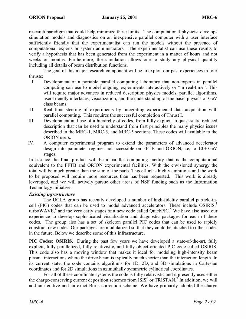
ORION Proposal January 25, 2001 MRC-6
MRC-6 Page 2 of 9
research paradigm that could help minimize these limits. The computational physicist develops simulation models and diagnostics on an inexpensive parallel computer with a user interface sufficiently friendly that the experimentalist can run the models without the presence of computational experts or system administrators. The experimentalist can use these results to verify a hypothesis that has been generated from the experiment in a matter of hours and not weeks or months. Furthermore, the simulation allows one to study any physical quantity including all details of beam distribution functions.
The goal of this major research component will be to exploit our past experiences in four thrusts:
I. Development of a portable parallel computing laboratory that non-experts in parallel computing can use to model ongoing experiments interactively or �in real-time�. This will require major advances in reduced description physics models, parallel algorithms, user-friendly interfaces, visualization, and the understanding of the basic physics of GeV class beams.
II. Real time steering of experiments by integrating experimental data acquisition with parallel computing. This requires the successful completion of Thrust I.
III. Development and use of a hierarchy of codes, from fully explicit to quasi-static reduced description that can be used to understand from first principles the many physics issues described in the MRC-1, MRC-3, and MRC-5 sections. These codes will available to the ORION users.
IV. A computer experimental program to extend the parameters of advanced accelerator design into parameter regimes not accessible on FFTB and ORION, i.e, to 10 + GeV stages.
In essence the final product will be a parallel computing facility that is the computational equivalent to the FFTB and ORION experimental facilities. With the envisioned synergy the total will be much greater than the sum of the parts. This effort is highly ambitious and the work to be proposed will require more resources than has been requested. This work is already leveraged, and we will actively pursue other areas of NSF funding such as the Information Technology initiative. Existing infrastructure
The UCLA group has recently developed a number of high-fidelity parallel particle-in-cell (PIC) codes that can be used to model advanced accelerators. These include OSIRIS,3 turboWAVE,4 and the very early stages of a new code called QuickPIC.5 We have also used our experience to develop sophisticated visualization and diagnostic packages for each of these codes. The group also has a set of skeleton parallel PIC codes that can be used to rapidly construct new codes. Our packages are modularized so that they could be attached to other codes in the future. Below we describe some of this infrastructure. PIC Codes: OSIRIS. During the past few years we have developed a state-of-the-art, fully explicit, fully parallelized, fully relativistic, and fully object-oriented PIC code called OSIRIS. This code also has a moving window that makes it ideal for modeling high-intensity beam plasma interactions where the drive beam is typically much shorter than the interaction length. In its current state, the code contains algorithms for 1D, 2D, and 3D simulations in Cartesian coordinates and for 2D simulations in azimuthally symmetric cylindrical coordinates.
For all of these coordinate systems the code is fully relativistic and it presently uses either the charge-conserving current deposition schemes from ISIS6 or TRISTAN.7 In addition, we will add an iterative and an exact Boris correction scheme. We have primarily adopted the charge

ORION Proposal January 25, 2001 MRC-6
MRC-6 Page 3 of 9
conserving current because they allow the field solve to be done locally, i.e., there is no need for a Poisson solve that requires global communication. The code uses the Boris scheme to push the particles, and the field solve is done locally using a finite difference solve for the E and B fields in both space and time. The code has the moving window as an option and it allows for domain decomposition for any number of dimensions. Benchmarking of the code has indicated that the additional overhead from using an object oriented framework in Fortran 90 leads to only a 15% slowdown in speed.
Visualization. We have spent considerable time developing diagnostic and visualization routines for understanding the output from our parallel PIC codes. It is not an exaggeration to say that visualization is a major part of a parallel-computing lab. The data sets from current simulations are both large and complex. To deal with this, we have adopted the use of HDF format. This format is rapidly becoming the standard for scientific output. Its implementation has made data output very flexible and platform independent.
Using the IDL language, we developed a large set of data-analysis tools, which range from simply interfacing the simulation data with the visualization routines, to advanced spectral, envelope and centroid analysis. In addition, we have isosurface generation, volume rendering, streamline generation, and slice and projection routines. The analysis is done locally: relevant data is downloaded from the supercomputers used and processed in the machines in our group. One of the advantages of this procedure is that it allows us to save on supercomputer usage, especially storage space, also allowing for a higher degree of interactivity. We have also used IDL for connecting simulation results to the experimental results, by using it to transport our simulated particles to virtual detectors on the experiment.
Skeleton parallel PIC codes. Besides having written large and complicated production codes such as OSIRIS, we also have developed a set of skeleton Parallel PIC codes. These were originally designed for developing new algorithms and exploring new parallel computer architectures.8 They are deliberately simple, containing only the critical pieces needed for depositing charge, advancing particles, and solving the field, with limited diagnostics. The algorithms developed with the skeleton codes were then incorporated into a parallel PIC library called PLIB, which is used in a number of grand challenge calculations including the one on modeling accelerators. PLIB was designed to hide the internal details of parallel programming from scientific programmers, and consisted largely of data management routines specialized for parallel PIC codes. These codes have also been extensively benchmarked, providing data that was useful for benchmarking the performance of other parallel PIC codes.
Recently, this group of skeleton codes is evolving into a Parallel PIC Framework. A Framework is a unified environment containing all the components needed for writing code for a specific problem domain. The PIC Framework contains a skeleton main program, along with a number of useful subroutines from UCLA's 25-year history of PIC codes. The goal is the rapid construction of new PIC codes from available parts. It makes use of classes and wrapper functions written in Fortran90 to provide simple interfaces and encapsulate complex Fortran77 legacy subroutines,9 ensuring plug and play compatibility of the parts. The framework is designed to support multiple numerical methods, optimization strategies, different machine architectures, and so forth. Thrust I: Code Development A new 3D quasi-static parallelized PIC code. For many situations of interest the drive beam evolves on a much longer time scale than the plasma frequency. In these cases the beam appears

ORION Proposal January 25, 2001 MRC-6
MRC-6 Page 4 of 9
static or frozen for long periods of time, and one can make the quasi-static or frozen field approximation. We believe it should be possible to develop a parallelized quasi-static PIC code for modeling particle beam drivers. This code would combine all the best features from WAKE10 and the work of Whittum.11 We have already begun to put a prototype version together by using the skeleton parallel PIC codes. Basically we have imbedded the 2D parallel PIC code inside of the 3D parallel PIC. Our fully explicit PIC codes such as OSIRIS are important tools for verifying reduced models such as quasi-static PIC codes. Over time we will add more physics into the reduced description code depending on the problem being studied. Results from this code will also allow us to determine a set of parameters to use in our more accurate codes.
Continuing the development of OSIRIS and its visualization/diagnostic packages. While OSIRIS is currently running in a production mode on several parallel platforms and it has a wide range of visualization options, we propose to improve and maintain it. In particular, an initial project is to ensure that it scales to new parallel computing architectures such as multi-node multi-processor machines. We will also optimize its speed and add a Boris field solve using a parallel FFT routine which we already use in other codes for the Poisson solve. We will also add additional physics packages such as tunneling and impact ionization, and new types of boundary conditions. We also plan on adding a dynamic load balancing routine and static mesh refinement. In regards to visualization we will further automate the making of movies and utilize IDL to make some runtime diagnostics for parallel computation.
Project Appleseed (User friendly parallel computing). An important part of Thrust I that is necessary for Thrust II is the development of a portable user friendly parallel computing facility. One possibility that we have already found to be extremely useful is what we call Project Appleseed.12 Project Appleseed is a parallel cluster based on the Apple Macintosh, similar to Beowulf type systems based on Linux. The standard Macintoshes have high-end processors, which include a 4 GFlop vector co-processor, and gigabit networking. Furthermore, scientific codes can be directly coupled to professionally written, high quality visualization software, such as IDL. While this work will initially be directed towards Macintosh clusters many of the concepts could be incorporated into other platforms because we will use standard tools such as MPI. Even a small cluster can have a dramatic impact on the computational abilities of small groups. For example, we have performed 3D PIC calculations with 50 million particles at 13 seconds/time step. Such a calculation could only be done on the world�s largest machines only 5 years ago.
To build a Macintosh cluster, we wrote an MPI library (based on Apple�s Open Transport), as well as a utility called Launch Den Mother (LDM) for discovering available machines and launching jobs on them. This software is freely available on our web site,13 and more than 15 Macintosh clusters have been built around the world using it. Because of its ease of use, high school students have built a number of parallel clusters. Since we are targeting non-expert programmers, we have made special efforts to make MPI friendly, with visual monitors and extensive logging facilities.
Soon Apple will migrate to MacOS X, which is based on Unix. As part of our migration to MacOS X, we plan to rewrite LDM to be TCP/IP based, and thus enlarge its scope to wide area networks. With MacOS X, one can migrate complete public domain versions of MPI to the Macintosh, and no longer needs to rely on MacMPI. However, because we have added many features to MacMPI to make it easier for students to debug and monitor their parallel programs, we plan to continue to support it. Furthermore, by controlling our own version of MPI, we can add new, user-friendly and useful features in the future.

ORION Proposal January 25, 2001 MRC-6
MRC-6 Page 5 of 9
We want to better integrate parallel computing with commercial visualization programs, such as IDL. Since one typically does not have access to the source code of such programs, one has to control such activity via other means, such as scripting languages. We have already had some success with a test AppleScript program that observed when a new data file was generated by a running parallel program, and then sent a request to IDL to display it, so this approach appears promising. Thrust II: Real-Time Computing
Carrying out experimental research at state-of-the-art facilities such as the FFTB and ORION is expensive in both man-hours and operational costs. Modern information technology and high performance computing can have a major impact of research efficiency. While high power computing involving massively parallel production runs played a major role in the successful interpretation of these experiments, the simulation effort and the experimental effort were not coupled in real time. The data was taken at a furious pace � 5 Mbytes on each event at a rate of 1 Hz for 24 hours/day; and the simulations were performed over a period of weeks on up to 64 nodes of the Cray T3E at the NERSC facility. The goal of this thrust is to synchronize the experimental and simulation data taking.
Real-time feedback. An important task of Thrust II is to provide efficient post-processing of experimental data on a time scale short enough (ten minutes or less) to provide useful feedback on experimental conditions. The first stage involves determination of basic experimental conditions to ensure they are correct. Currently, this is done by manually transferring several measurements from the experiment to a PC running MatLab. A calculation up to an hour in length is then carried out. We propose to develop algorithms to enable this calculation to be done 10 - 50 times faster. There are several possible approaches. One is to have a master node partition the work and assign pieces to a local cluster consisting of the PC�s running MatLab and collecting data. The challenge here is to determine how to communicate effectively across heterogeneous platforms with foreign programs to which one does not have access to the source. If this does not give the required speedup, then we will experiment with grid techniques such as high-throughput computing and parallel processing on heterogeneous, remote compute resources.
Integration of Simulation and Experiments via Computational Grid Technology. An ambitious aspect of Thrust II is integrating our existing simulation and analysis methods with experiments. Using simulation results to guide experiments is likely to prove more effective than using the results of experimental analyses, since simulation results often provide additional physics insights beyond merely the state of the experiment. This will take place in two phases. First we will bring parallel computing into the laboratory using the reduced description PIC code. Care will be taken to design this code such that it will run on a parallel cluster local to the experiment with a user-friendly interface and real time visualization. In this way the experimenters can obtain insight in a short enough time to influence the experiment (i.e., minutes to hours).
Second, we will fully integrate our experimental analysis and simulation tools in a computational grid infrastructure. Grid integration enables local processing on a cluster, or reaching out for larger resources on demand when required. Two PI�s of the IT proposal (Prof.Carl Kesselman and Dr. Ann Chervenak from USC) have developed a grid computing environment called Globus.14

ORION Proposal January 25, 2001 MRC-6
MRC-6 Page 6 of 9
Several features of computational grids will be used in our application. For example, grid environments include services for discovering computational and storage resources at remote locations. Once these resources are identified, grids will allow us to reserve the use of these resources for later computation and to schedule a collection of resources to cooperate on a computation. Data management services in computational grid environments will provide efficient data transfers as well as management of multiple replicas or cached copies of files. Finally, grid environments will provide capabilities for tele-observation and control of the experimental apparatus, allowing researchers at remote sites to monitor the experiments and interactively change parameter settings. Thrust III: Development and Use of a Hierarchy of Codes
We will use the hierarchy of computational tools to simulate many of the proposed experiments of the ORION PFC center. The modeling efforts of MRC-1 and MRC-5 are already clearly integrated into the simulation effort. Part of this thrust is to integrate the modeling for MRC-3 into this main effort. This will initially be done in several ways. The MRC-3 beamline simulations will produce the model predictions of the actual beams in the ORION experiments. As these beams have intricate phase space correlations, this effort is needed to accurately understand the details of the beam-plasma interaction experiments. Thus, we plan to use the results of the beam physics modeling codes as inputs into the plasma codes to produce end-to-end simulations from the cathode of the photoinjector to the output from the plasma.
The parallel PIC codes described above will also be applied to study basic beam physics issues related to intense relativistic beams, with an emphasis on 3D effects. In this way, simulations of fundamental phenomena involving non-inertial (bending) systems, and collective radiation effects (coherent transition and synchrotron radiation) can be undertaken. As an example of recent relevant radiation studies, the UCLA simulation group has recently been studying ion-channel lasing. Currently, such efforts are limited by the disparity in scale between the output radiation and the betatron wavelength. Therefore, our present algorithms can be used to study the coherent radiation from low gamma beams. Alternative algorithms will be investigated for high gamma beams. Furthermore, a major effort will be made to parallelize the 2D PIC photoinjector code ITACA15 using some of the skeleton PIC code libraries from the UCLA PIC group. In these ways, we will bring state-of-the-art computational tools developed primarily for plasma physics to bear on pressing, and as yet unresolved, issues in beam physics.
The MRC-1 and MRC-5 experiments are ideally suited for full-scale modeling because the physics is highly nonlinear, and our hierarchy of parallel PIC codes will be essential for proper understanding. In fact, simulations have already proven essential in interpreting E-157, the initial experiment at the FFTB. Furthermore, they have already been used extensively for preliminary studies of positron wakes, self-trapping, lensing, hosing, diffraction of particle beams, ion-channel radiation, beam loading and the effects of bunch shaping on transformer ratios. Examples have already been presented in previous MRC�s, e.g., see Figures 1.1, 1.2, and 1.4 in MRC-1 and Figures 5.2 and 5.3 in MRC-5.
The richness of the physics and our simulation capability is further illustrated in Figure 6.1 where we show results from a plasma wakefield simulation using OSIRIS. The images are multiple isosurfaces of the accelerating fields; the parameters correspond to those in E-157. The simulation followed 6×10⁷ particles on 1.4×10⁷ grids. In the plots on the left the drive beam had a symmetric cross section, while on the right it was asymmetric. The colors correspond to a particular value of the accelerating field. The figure illustrates that asymmetric drive beams lead

ORION Proposal January 25, 2001 MRC-6
MRC-6 Page 7 of 9
to smaller regions of accelerating fields than symmetric ones. This figure also illustrates the sophisticated visualization techniques that are available.
Another example of the physics is shown in Figure 6.2 that shows the amount of hosing one might expect for three cases. On the left we show the initial beam and the final beam for E-157, i.e., a GeV class stage. In the middle we show hosing for a wedge shaped beam, which is
Figure 6.1. Isosurface plots for symmetric and asymmetric drivers for parameter close to those in E-157.
s = 0.0 m
s = 1.4 m
s = 0.0 m
s = 0.21 m
s = 0.0 m
s = 4.8 m
AfterburnerWedge beamE-157
Figure 6.2. Color contour plots of a beam with an initial linear tilt, with 1.8×10¹⁰ particles, and (left-hand panel) a bunch length of 0.63mm (one c/ωp long) and spot size of 70 µm, (middle panel) a wedge shaped beam c/ωp long, and (right-hand panel) a bunch length of 0.063mm (one c/ωp long) and a spot size of 7 µm.

ORION Proposal January 25, 2001 MRC-6
MRC-6 Page 8 of 9
longer in normalized units. The amount of hosing is larger as is expected. Finally, on the right we show the beam for a 10 to 100 GeV class stage which might be possible if the E-157 bunch were shortened by a factor of ~10. In this case hosing is dramatic and it erodes away the back half of the beam. Importantly, the amount of hosing in the simulations using short Gaussian shaped beams (the left and right) was considerably less than the is theoretically predicted. Thrust IV: Advanced Accelerator Design
The final component of our research program is the design and evaluation of a collider based on advanced accelerator concepts. This is a major challenge. The experimental parameters, both beam and plasma, currently available at FFTB and ORION cannot directly study 10+ GeV stages. The simulation of such a virtual collider is challenging since the largest parallel computers currently available require tens of thousands of hours of total CPU time to model even a single GeV stage with full resolution in three dimensions. We will take advantage of the results from the first three Thrusts that will provide comparisons between experiments and the hierarchy of simulation models, thereby elucidating the subtle physics issues associated with each level of approximation in our hierarchy. If the reduced models are successful in predicting experimental results, we will apply them to the challenge of simulating a full-scale collider based on plasma wakefields. Furthermore, these codes will be the major tools for studying the key physics of afterburners that were outlined at the end of MRC-1. The results will provide the community with a blueprint for realizing a compact collider that can extend the frontier of high-energy physics.
There is much interesting physics to be explored in order for such a collider to become a reality. Some of the key physics were already delineated in MRC-1. 1 J. M. Dawson, �Particle simulation of plasmas�, Scientific American 260, 34 (1989); Review of Modern Physics 55, 403 (1983); J. M. Dawson, �Plasma particle accelerators, J. M. Dawson et al, Physics Today 46, 64 (1993); V.K. Decyk, Supercomputer 27 v5, 33 (1988). 2S. Lee, T. Katsouleas, R.G. Hemker, and W.B. Mori, "Simulations of a meter long plasma wakefield accelerator," Phys. Rev. E. 61, 7014 (2000); R.G. Hemker, W.B. Mori, S. Lee and T. Katsouleas, "Dynamic Effects in Plasma Wakefield Excitation," Phys. Rev. Spec. Top.-Acc. & Beams, 3 061301(2000). 3 R. G. Hemker et al, �Development of a parallel code for modeling plasma based accelerators,� Proceedings of the 1999 Particle Accelerator Conference, New York, NY, 5, 3672 (1999). 4 D.F. Gordon, W.B. Mori and T. Antonsen, Jr., "A Ponderomotive Guiding Center Particle-in-Cell Code for Efficient Modeling of Laser-Plasma Interactions," Submitted to IEEE. 5 Chungkun Huang et al., to be presented at PAC 2001. 6 R.L.Morse and C.W.Neilson, Phys. Fluids 14, 830 (1971), see Appendix B. 7 J.Villasenor and O.Buneman, �Rigorous charge conservation for local electromagnetic field solvers,� Computer Physics Communication, 69, 306 (1992). 8 V. K. Decyk, "Skeleton PIC codes for parallel computers," Computer Physics Communications 87, 87 (1995). 9 V. K. Decyk and C. D. Norton, "Modernizing Fortran77 Legacy Codes," Proc. Conference on Computational Physics (CCP2000), Gold Coast, Australia, Dec., 2000, p. 104. Submitted to Computer Physics Communications. 10 P.Mora and T.A.Antonsen Jr Phys. Plasmas 4, 217 (1997). 11 David H.Whittum, Phys. Plasmas 4, 1154 (1997).

ORION Proposal January 25, 2001 MRC-6
MRC-6 Page 9 of 9
12 V. K. Decyk, D. E. Dauger, and P. R. Kokelaar, "Plasma Physics Calculations on a Parallel Macintosh Cluster," Physica Scripta T84, 85 (2000). 13 http://exodus.physics.ucla.edu/appleseed/ 14Andy Eddy, �Computational grid taps network power (Globus Ubiquitous Supercomputing Testbed,�, Network World 14, 29 (1997). 15 L.Serafini, C.Pagani, Proc. 1st EPAC, Rome, June 1988, Ed. World Sci., p.866.

ORION Proposal January 25, 2001 Education and Outreach
Education and Outreach Page 1 of 3
Education and Human Resource Development Introduction and Overview
The education outreach program of the Center has four complementary, interrelated components designed to leverage existing programs at SLAC and the California Community Colleges. First, we would develop partnership programs with local community colleges located in the Los Angeles and Bay Areas that involve their faculty and students in the development and research activities of the Center. To enhance and sponsor these programs as well as the many research programs at the Center, an interactive, state-of-the-art website related to the Virtual Visitor Center (VVC) at SLAC will be developed. This site can then be used to support other components, including an �expert partners� program that is subject-based and involves interested engineers, scientists and technicians (both active and retired) as well as the community outreach program that includes tours, lectures and classes for the general public.
The mechanics of how these components will be implemented to maximize their overall impact is outlined below. The synergy between them is such that each benefits the others. For instance, students may use the website to gain background before coming to the lab, while student project reports, done with expert partners, may be used to augment site content. Segments from videotapes of courses and talks will provide a growing resource of additional web-material. Costs, quality and efficiency should be improved by integrating these efforts with the ongoing education and outreach programs at Stanford, UCLA, USC and SLAC. These include active tour programs, summer internships for undergraduates with emphasis on groups that are under-represented in science, a well-traveled public outreach website, and high quality exhibits on the physics and technology of accelerators.
O u t r e a c h w i l l u s e t h e w e b t o s c h e d u l e a n d p u b l i c i z e p r o g r a m s w h i l e t h e w e b w i l l i n c l u d e Q & A , F A Q s , c o u r s e s a n d c o n t e n t .
O R I O N
W e b S i t e ( V V C )
O u t r e a c h
E x p e r tP a r t n e r s
C o m m u n i t yC o l l e g e s
S i t e D e v e l o p m e n tC o n t e n t / Q & A R e s o u r c e
O u t r e a c h P r o j e c t s T o u r s a n d T a l k s
S i t e D e v e l o p m e n t C o u r s e M a t � l / P r e p .
E x h i b i t s T o u r s
Community College Partnerships
Community colleges are the education sector that receives the least share of federal funding and yet serves the largest proportion of students from minority or financially disadvantaged backgrounds. There are more than 100 community colleges in California with 23 in the Bay Area near Stanford and Berkeley with 58 more in southern California concentrated close to Los Angeles and San Diego. Thus, any University user group in California is quite likely to have a potential community college partner in its vicinity.
The Center�s program will begin by developing partnership programs with selected, local community colleges. The major goal of these partnerships would be to increase the number of students in physics and engineering that transfer to four-year colleges. In the first summer, one or more physics or engineering faculty from each partner community college would be invited to spend a month or more as paid research interns at the Center. Working in concert with members

ORION Proposal January 25, 2001 Education and Outreach
Education and Outreach Page 2 of 3
of the various research teams, who would give tutorials on their programs, they would then have the responsibility to develop a plan for the ongoing partnerships that would best serve their students and integrate the science of the Center into their teaching programs.
While the details of the on-going partnership program will be determined in response to the plans developed in the first summer, we believe that it is possible to design courses that provide first-hand knowledge and experience of forefront research and technology to students but also facilitates their making meaningful contributions to the Center. We think this is a reasonable expectation because the students will have taken (or will be taking) courses in computers, calculus and electromagnetism while advanced accelerator research in many respects is synonymous with research in electromagnetism.
Students selected for the laboratory partnership program could develop relationships with several expert partners and other students while working over variable periods of not less than one quarter on specific research projects. Stipends would allow them to dedicate regular and significant time in an educational environment and also receive course credit. (We have received commitments on this already.) Most research projects have a number of specific problems that can be done in one quarter at the kind of facility envisioned here. Diagnostics, computational modeling and visualization problems are ideal examples of hands-on problems that can be done in a single quarter but stimulate a lifetime of rewarding work.
Community college faculty would benefit from the linkage to working scientists and would supplement what the students receive in the workplace, link course material and tools to the research, and provide crucial perspective and motivation. Stipends for teachers working with Center members would allow them the time and resources to develop the courses and materials that best augment the research programs that benefit their students and the Center. ORION Website
Teachers and students both state that the Web is a major teaching and learning tool. To capitalize on this, the Center�s website will include interactive activities and events designed for use by teachers from high school and community college physics and engineering programs. One advantage we can offer is real time data for student projects - something not generally available to most community college classrooms.
We intend to use an award-winning site, developed at SLAC, called the "Virtual Visitor Center" (VVC) http://www2.slac.stanford.edu/vvc/home.html as a starting point for the Center�s outreach site. The VVC provides basic information to students and the public on many aspects of SLAC�s research. The ORION site could be built directly on this base and in concert with other upcoming laboratory efforts to expand and enhance the VVC site. New features will include web access to experimental and engineering data, simulation tools for students and a question and answer service. New elements that we will include are interactive course elements and teaching modules developed with community college faculty and expert partners. These could be significant extensions to FAQs and Q&A services.
We would expect every project that uses the facility for any significant period of time to provide a web-based description of their research that is targeted at high school and community college students that would be reviewed and modified in collaboration with CC faculty and students. Such material, when posted, would provide a growing library of information on the Center�s work and achievements. Community Outreach Opportunities
SLAC and the ORION collaboration have a wealth of human resources in their current and recently retired technical people. The Center will work as a focal point to gather and

ORION Proposal January 25, 2001 Education and Outreach
Education and Outreach Page 3 of 3
mobilize this pool of talent to participate in specific activities with students, teachers and the general public. For example, some of these people will act as expert partners to community college faculty and interns. They would also participate in the interactive website by providing feedback in the Q&A section as indicated in the diagram.
Expert partners who are experienced communicators and educators will provide courses or public lectures for lay people with an interest in accelerator physics and associated ES&H issues. The Center�s program and its leaders commit to providing several, well publicized lectures each year.
Specialized and in-depth tours of research areas will be conducted for students as part of an ongoing and active tour program at SLAC. In all of these activities, there is a circularity, in that the target audience is instructed by scientists and then are able to explore further using the web as well as to spread this information themselves e.g. from the interns to their classmates. Measuring Program Impact
While we have reserved the site http://www.PhysicsFrontiers.org, we suggest using it, or an existing NSF site, for links to other Centers and for administrative requirements of common interest to all Centers. One common element is the need to measure and monitor progress and obtain feedback in a uniform, unbiased way. While monitoring such things as the number of times a site is accessed, its rate of change and the mean dwell time are important measures, the measure of a program�s impact is more complicated. For such purposes, it is useful to query individuals, in some way, both before they enter and before they leave a site or a program. For student interns, it is important to require, at a minimum, an application and an exit evaluation from them (and their instructors and partners) at an independent website. Some goals of this process would be to compare what they expected to what they achieved and to assess whether their expectations or motivation for professional careers improved. Because this is an ongoing program, intern fellowships could be awarded to previous interns to participate in the current summer session and to perform follow-up on the interns from their year. Final Comments and Acknowledgements
We studied many programs to see where we might use them directly or augment them in meaningful ways. As noted, existing university undergraduate and graduate research programs in advanced accelerator physics are attractive to young people. Such students provide an important and ongoing peer group for prospective students from community colleges.
The proposal benefited greatly from many conversations, phone calls and email from people involved in virtually every phase of such programs � including expressions of interest in participation from several community college faculty members from Los Angeles to San Francisco (corroborating letters and email are available). At SLAC, Dr. Helen Quinn provided many suggestions and has promised support for the resulting program that should gain good leverage from existing programs and resources such as the VVC. Dr. Kenneth Kase, Associate Director in charge of ES&H at SLAC, has also expressed an interest in working with the Center on community outreach and education at the community college level.
From such considerations, we can construct a very effective program for an annual budget of 3% of the Center�s total yearly budget. In addition, the USC group will use some of their university matching funds to develop an exhibit and live presentations at the California Science Center highlighting the physics of accelerators with Dr. Diane Perlov, Deputy Director of Exhibits. Since this is of general interest, we are also pursuing additional funds for this from the American Physical Society since it provides such good public outreach and broad range of student projects.

ORION Proposal January 25, 2001 Shared Facilities
Shared Facilities Page 1 of 1
Shared Experimental Facilities At inception, the Center�s physics program will be located at the FFTB which is an
operational 30 GeV e+/e- beam line located North of and in the vicinity of the ORION Facility. Various laser facilities and user control rooms are located in and around the FFTB complex. The FFTB has two fully diagnosed interaction regions, which will be used for plasma acceleration experiments. The FFTB is a shared SLAC facility that is available through proposal submission to SLAC and peer review by the SLAC Experimental Program Advisory Committee.*
The ORION Facility described in detail in MRC-2 is a shared facility that is a major part
of this proposal. The reader is referred to that MRC for a description of the facility, staffing and operations plans. Allocation of time at the facility is discussed in the Management section and is repeated here for clarity.
�The allocation of the ORION Facility experimental time will be modeled after the �Participating Research Teams� of the synchrotron light community. The developers of the facility will have 75% of the available time for their research. It is anticipated that some of this time will be used for research performed by collaborations between ORION scientists and others who are not part of this proposal. These collaborations will form in the usual, informal ways by scientists with shared interests. The remaining 25% of the time will be available to the general user community with the allocation of that time based on the recommendations of a Program Committee, which will discussed in detail below.� (That discussion is in the Management section.) There are resources at the collaborating institutions that are not part of the Center but
could be available for Center related research. These include: • At UCLA
1. Prototyping facilities of the Electrical Engineering and Physics Departments. 2. The Center for High Frequency Electronics. 3. The NEPTUNE and PEGASUS Laboratories. 4. The existing Appleseed cluster and the enhancements to that are funded through
this proposal. • At USC
1. The National Center for Integrated Photonic Technology. 2. The Keck Photonic Center.
• At Stanford 1. The Center for Nonlinear Optical Materials 2. The Center for Integrated Systems
• At SLAC 1. Physical Electronics facilities. 2. Mechanical prototyping at the Light Fabrication Facility. 3. The Stanford Synchrotron Radiation Laboratory
* The ORION Board and Program Committee discussed in the Management section will review the MRC-1 experiments, but they do not allocate time on the FFTB.

ORION Proposal January 25, 2001 Other Sectors
Other Sectors Page 1 of 2
Collaboration with Other Sectors Collaboration between universities and national laboratories will be central to the ORION
Center�s activities. The Center is designed to stimulate interactions between physicists and new collaborations will arise through these interchanges.
In addition, working with industry has been a hallmark of the research activities of four of the six PI�s in this proposal, and it will continue as a facet of the program. Many of the Center�s research topics have the potential of industrial interest since the process of turning new accelerator concepts into experimental tests at ORION will place a premium on the use of cutting-edge technologies. These include precision fabrication of micro- and nano-electro-mechanical devices, electron sources, high-frequency, high peak power lasers, ultra-fast diagnostics, and high-speed advanced computing.
The PI�s will collaborate with industry through the Small Business Innovative Research (SBIR) program. This program has proven to be mutually beneficial to industrial and academic participants and has traditionally fostered rapid exchanges of knowledge. The industrial participants benefit from the forefront knowledge and unique instrumentation available at the universities and laboratories, and the academic participants gain access to state-of-the-art fabrication methods and, in some cases, end products.
The close relationships with industry will continue, and new ones will develop through the work and associations taking place at the Center. Possible SBIR collaborations related to the Center�s activities include • Development of an 11.4 GHz standing wave/traveling wave hybrid photoinjector, as
discussed in MRC-3 • Efficient lasers in the 1.6 to 2.5 micron wavelength range for powering microstructures
made from silicon or quartz, as discussed in MRC-4 • Silicon microcircuit-based charged particle optical elements for particle beam focusing in
lithographically based accelerators • A laser-driven �matrix-cathode� source for producing parallel electron-beam bundles to
avoid the space-charge limits in high-energy collider beams.1 Past Collaborations with Industry
Prof. R. Byer has extensive involvement with the laser and optics industries. He is the co-founder of Quanta Ray, Inc. and Lightwave Electronics Corp. and has served on the Board of Directors of General Lasertronics Corp.
Other PI�s are presently or have participated in seven SBIR collaborations in lasers and optics, electron sources, micro-machining, and RF structures. These are given in the Table on the next page. Some of these have direct impact on the ORION Center. For example, the existing DOE Phase I SBIR with Betadot, Inc. will lead to a new high-density plasma source for plasma acceleration experiments.

ORION Proposal January 25, 2001 Other Sectors
Other Sectors Page 2 of 2
Table: Recent Small Business Innovative Research Collaborations Topic Small Business Firm
Electrical Discharge Machining Application to the Development of MM-Wave Accelerating Structures (DOE Phases I & II)1
Ron Witherspoon, Inc
Mass Production of Millimeter-Wave Accelerating Structures Using Precision Metal Forming Technology (DOE Phase I)1
Dayton Reliable Tool & Mfg. Co
Design of a 10 MW, 91 GHz Gyroklystron for Linear Accelerators (DOE Phase II) 2
Calabazas Creek Research
Development of a Plane-Wave Transformer Integrated Photoinjector (DOE Phase II) 3
DULY Research, Inc.
Ultra-High Brightness X-band Integrated Photoinjector (DOE Phase II) 4
DULY Research, Inc.
A One-Meter, 300 GHz to 1 THz, Plasma Accelerating Structure for Advanced Accelerator Applications (DOE Phase I) 5
Betadot, Inc
Table-Top, Two-Frequency, Terawatt Laser System for Plasma Beat-Wave Acceleration Experiments (DOE Phase II) 6
Positive Light, Inc.
Notes regarding affiliations with the ORION Center: 1) R. Siemann and D. Palmer are collaborators. 2) Work leading to a 91 GHz power source that has been specified in part by R. Siemann, E.
Colby and D. Palmer. It will be available for their research. 3) Work leading to a Photoinjector that has been specified in part by J. Rosenzweig. It will be
available for his research. 4) J. Rosenzweig is a collaborator. 5) C. Joshi is a partner in Betadot, Inc. 6) Work leading to a laser that has been specified in part by C. Joshi. It will be available for
his research. 1 J.E. Spencer, �Limitations Imposed by Beam-Beam Effects and Their Remedies�, Int. J. Mod. Phys., Vol A13, p.2479 (1998) and �Limitations Imposed by Beam-Beam Effects and Their Remedies-II�, Int. J. Mod. Phys., Vol A15, p.2543 (2000)).

ORION Proposal January 25, 2001 Internation Collaboration
International Collaboration Page 1 of 1
International Collaboration There will be two aspects of international collaboration at the ORION Center. Substantial
interest has been expressed by international laboratories in addition to SLAC and by users outside the U.S. interested in collaboration and/or independent experiments.
Dr. Hirotaka Sugawara, Director-General of KEK, the Japanese high-energy accelerator laboratory, and Dr. Albrecht Wagner, Chairman of the Board of Directors of DESY, the German synchrotron laboratory, have both expressed the opinion that ORION is an important project for the worldwide program of accelerator development. They have expressed their interest in having their laboratories join ORION in letters that have been submitted in support of this proposal.
Dr. S. Kurokawa has been named as the contact person from KEK, and he is planning to propose a collaboration on ORION to the Japan/U.S. Cooperation in High-Energy Physics program. DESY will nominate one of its accelerator scientists as ORION contact early this year, and will begin to explore possible contributions to the Center. Each of these laboratories will have a representative on the ORION Board.
Both KEK and DESY have a long history of accelerator research and development, and their participation in the Center�s activities will broaden its base of experience and creativity. KEK has a demonstrated capability of fabricating prototypical devices for accelerator research, and DESY a notable record of achievement in adapting new technologies to accelerator applications. Scientists and students from these laboratories are expected to participate in experiments of mutual interest at ORION, and a strong current of intellectual cross-fertilization will connect the global participants, making ORION a truly international Center.
The other aspect of international collaboration will involve individual scientists who will interact with the PI�s and join or originate new experiments. Two examples were mentioned in MRC-3 and MRC-4. Dr. Luca Serafini of the University of Milan has written a letter, which is on file, expressing the interest of his group to collaborate on various photoinjector research topics at ORION and also on advanced computational techniques. His group has many years of experience in high-brightness electron source design in collaboration with Prof. J. Rosenzweig and Dr. D. Palmer of this proposal. Dr. Levi Schächter of Technion, the Israel Institute of Technology, has also written in support of the ORION concept and has initiated discussions with Prof. R. Siemann and Dr. E. Colby of this proposal to investigate the Amplified Cherenkov Wakefield Accelerator at ORION.
An added benefit of the participation of enthusiastic, creative scientists from the international academic community will be the attraction of first-rate students to ORION. The education and experience gained by these students will in many cases be taken back to their home institutions overseas, expanding the Center�s influence in education.

ORION Proposal January 25, 2001 Seed Funding
Seed Funding Page 1 of 1
Seed Funding Advanced accelerator research is characterized by innovative thinking that leads to lively
discussions at conferences and a steady stream of publications in prestigious journals. Many of the ideas are conceptual in nature, and a necessary next step in the development is often experimental. Proof-of-principle must be demonstrated, strengths and weaknesses discovered, and, almost always, new insights and directions will arise. Experimentation can be difficult for the reasons discussed in the body of this proposal: conventional aspects are often essential but require substantial effort; special resources, such as a state-of-the-art electron source may be needed; sophisticated diagnostics may be necessary, etc.
The underlying philosophy of the ORION Center is to provide support, resources and flexibility that will allow quick response to new opportunities. This philosophy shares much in common with that intended for seed funding, and this aspect of seed funding cannot be separated in a budgetary sense from the body of the proposal.
There is increasing realization of the importance of accelerator research for the future of particle physics, and this is leading to new interest from scientists trained in high-energy physics and young faculty who see accelerator research as a significant, promising field. We will encourage these people to come and work at the ORION Center in collaboration with an ongoing experiment. In that way they will be immersed in a dynamic research environment, receive hands-on experience, and develop initial contacts in the field. The budget includes seed funding to support sabbatical visits of these scientists.
The computer modeling aspect of this proposal offers other opportunities. A portion of the UCLA matching funds will be used to establish a Center For Particle-In-Cell Computing. One goal of that Center is to give the UCLA plasma simulation group the flexibility to explore innovative and high-risk research concepts at an early stage before they are mature enough to obtain outside funding. These funds will also be used to support students and post doctoral researchers on new problems that will arise as a result of the ORION Center�s activities.

ORION Proposal January 25, 2001 Management
Management Page 1 of 3
Management This proposal to the NSF is the keystone of a research center devoted to advanced
accelerator physics and technology. The analogy with a keystone is apt because there are several important elements making up the whole of the Center. All of them must be represented in the management plan. The underlying goals of that plan are
• To build and operate user-oriented experimental facilities that will make rapid progress possible,
• To bring together and support the research of a core group of physicists who will form a critical mass,
• Make those facilities available to other scientists in the realization that advances will come from insights and creative sparks from a diverse scientific community. The Center will be supported predominantly by the funds realized by this proposal.
These funds will be used to build and support the experimental program at ORION, and to support research at the Center of five of the PI�s (R. Byer, C. Joshi, T. Katsouleas, W. Mori and J. Rosenzweig).* A second important element is that the Center will be located predominantly at SLAC and will rely on SLAC accelerators and personnel for support. SLAC will be making significant financial and technical contributions to the Center, and the SLAC Director has designated the Associate Director of the Technical Division to have responsibility for SLAC aspects of the ORION Facility. A third element is that other laboratories in the US, Europe and Asia will be asked to become part of the Center, to help support it, and to utilize the facilities that will be available. To date KEK, the Japanese National High-Energy Physics Laboratory, and DESY, the Deutsches Elektronen-Synchrotron, have agreed to join. Laboratories that join the Center will have a role in administration and management.
There will be two different phases for the Center during the five-year period covered by this proposal. The components of the first one, lasting two to three years, will be experimentation at the FFTB, the construction and early operation of ORION, and computer modeling. In the second phase, the computer modeling will continue, ORION will be operating, and the experimental program will be concentrated there.
The allocation of the ORION Facility experimental time will be modeled after the �Participating Research Teams� of the synchrotron light community. The developers of the facility will have 75% of the available time for their research. It is anticipated that some of this time will be used for research performed by collaborations between ORION scientists and others who are not part of this proposal. These collaborations will form in the usual, informal ways by scientists with shared interests. The remaining 25% of the time will be available to the general user community with the allocation of that time based on the recommendations of a Program Committee, which will discussed in detail below. As mentioned above, five of the six PI�s will use funds from this proposal for personnel, materials and supplies, and capital equipment etc. for their research at the Center. The portion of the Center�s budget allocated to ORION operation will support all of the experimental activities as discussed in MRC-2. Consequently, collaborators and general users will have to secure support for their research through separate proposals.
Management of the Center is summarized in the Figure below. A Board, chaired by R. Siemann who will be Director of the Center, will manage the Center. It many ways it will
* R. Siemann�s research will remain part of the SLAC scientific program and continue to be supported through it.

ORION Proposal January 25, 2001 Management
Management Page 2 of 3
function like the leadership in a major scientific collaboration, but it will have some reporting responsibilities, also. The management and reporting functions of the Board are given in the Table 1. The Board membership will be
• The PI�s of this proposal - R. Byer, C. Joshi, T. Katsouleas, W. Mori, J. Rosenzweig, and R. Siemann.
• The ORION Project Engineer, D. Walz, and Project Physicist, R. Noble (acting). • The SLAC Associate Director of the Technical Division, Ewan Paterson. • Designees from contributing laboratories � S.-I. Kurokawa from KEK (others to be added
as they join the Center). Reporting will be to the Stanford University Dean of Research, and he will forward the reports to the UCLA Vice-Chancellor for Research, the USC Vice-Provost for Research, and the SLAC Director. The Board will meet bi-annually at a minimum.
Stanford UnivDean of Research
ORION BoardR. Siemann (Chair and ORION Director)
co-PI's - R. Byer, C. Joshi, W. Mori, J. Rosenzweig, T. KatsouleasProject Physicist - R. Noble, Project Engin.- D. Walz
SLAC Tech. Div. AD - J. PatersonLab. Reps. - S.-I. Kurokawa (KEK), TDB (DESY) ...
Program Committee
Education & OutreachCoordinator
MRC-1
MRC-2
MRC-3
MRC-5
MRC-4
MRC-6
SLAC TechnicalDivision
SLAC Support& Services
Table 1: Management and Reporting by the ORION Board Collaboration Management Oversee progress, review, and endorse major technical decisions related to the ORION Facility. (Primarily during facility construction) Provide guidelines for the operation and scheduling of the ORION Facility. (During facility operation) Act on recommendations from the Program Committee for general user experiments at the ORION Facility. Oversee the education and outreach activities. Receive and act on requests for seed money.
Report to the Stanford Dean of Research Status and health of the ORION Center. Status and accomplishments of each of the MRC�s. Status of the general user program including results, status of active experiments, a summary of Program Committee evaluations, and the subsequent allocation of time.
Figure: The ORION Center Management

ORION Proposal January 25, 2001 Management
Management Page 3 of 3
A Program Committee will provide the Board with independent scientific advice. This committee will be composed of scientists with an interest in advanced accelerators who are not part of ORION. Their functions are outlined in Table 2, and they meet at least once per year.
The Project Physicist and Project Engineer will handle day-to-day activities associated with ORION Facility construction, and the Project Physicist will manage facility operations once that phase is entered. This individual will implement the guidelines of the Board and be responsible for maintaining the operational schedule and budget taking into account readiness, beam requirements, and availability of unique instruments. The project Physicist will regularly prepare an operations summary for the Board and the Program Committee.
Based on aggregating 3% of the funds from participating institutions and the proposed education and outreach program, there will be a half-time staff member responsible for implementing the program and coordinating efforts in both Northern and Southern California where the Center has significant presence. This person will be an integral part of the Center who will be (1) encouraged to bring their own creativity to develop new programs, (2) responsible for fostering the interaction between Center researchers, teachers and students, and (3) overseeing the website development and operation.
The ORION Center will operate in accordance with the SLAC Environment, Safety and Health policies and requirements. It will receive support from the resident ES&H staff.
Table 2: Program Committee Evaluate proposals and make recommendations to the Board for general user experiments at the ORION Facility.* Criteria will include scientific importance, proponent�s track record, and suitability for ORION Review ORION operation and the progress of active experiments and provide advice to the Board on improving the program. Note: * The SLAC Experimental Program Advisory Committee makes recommendations about FFTB experiments to the SLAC Director

ORION Proposal January 25, 2001 Commitments
Commitments Page 1 of 1
Institutional and Other Commitments to the ORION Center The ORION Center has commitments from USC, UCLA, Stanford University, and SLAC
and expressions of interest and support from other institutions. Letters range from those from University Deans and Laboratory Directors, to those from Community College teachers. The letters demonstrate the breadth of impact that ORION will bring to all levels of the physics community. Letters Included in the Proposal
The following letters are included with the proposal. They all express strong support for the ORION Center and they make significant commitments to it. • Leonard Silverman, Dean of the USC School of Engineering. • Roberto Peccei, Vice Chancellor, Research, at UCLA. • Charles Kruger, Vice Provost and Dean of Research at Stanford University. • Jonathan Dorfan, Director of the Stanford Linear Accelerator Center. • Hirotaka Sugawara, Director-General of the KEK High Energy Accelerator Research
Organization. • Albrecht Wagner, Chairman of the Board of Directors of the Deutsches Elektronen-
Synchrotron DESY. Letters on File
There are letters on file that express support of the Center and interest in research there. • Adrian Melissinos, Prof. at Univ. of Rochester, in writing to describe a laser acceleration
experiment he proposes, notes �ORION is well-suited for this experiment because of the beam energy, beam emittance, and time structure. The availability of diagnostic and support facilities is equally important for the timely completion of the experiment.� And further, he notes, �I believe that a facility such as ORION is necessary to foster new developments in accelerator physics and to train doctoral and post-doctoral students in this field.�
• Levi Schächter, Associate Prof. at the Technion, indicates his strongest support for this proposal and writes, �As envisioned today, ORION will provide an excellent environment that combines the advantages associated with leading edge scientific research of a world-class academic institution like Stanford University, and the vast scientific expertise of a National Laboratory like SLAC. There is no other place in the world that beyond providing a 5�300 MeV beam, may also a deliver a 30 GeV beam from the main linac.�
• Luca Serafini of the University of Milan and INFN writes about the importance of the Center, �This is because it will gather a wide community working on advanced acceleration techniques (relevant to high energy colliders) from many Universities at a National Lab offering top scale facilities and a solid expertise in commissioning accelerators.� He also states his interest in working on MRC-3 and MRC-6.
From those teaching physics at the Community College level we are pleased to have notes from Annette Rappieyea, City College of San Francisco, who states, �it sounds like an excellent project�, while Joan Fu, Los Angeles Harbor College, tells us,��that would make it possible for team teaching (SLAC scientists and community college faculty), and for students here to learn from/communicate with expert scientists,� and , �to locate information from the web site.� Eric Harpess, Professor of Physics and Astronomy, Las Positas College, notes, �I applaud your ideas for the use of the world wide web to facilitate training and interaction between students and expert partners as well as making educational resources available to other interested students and faculty.�


