originalbetriebsanleitung translation of the original ... · originalbetriebsanleitung translation...
TRANSCRIPT

Originalbetriebsanleitung
Translation of the original Operating Instruction
KMD 188
2/2 Wege-Membranventil
2/2 Way Diaphragm Valve

Original-Betriebsanleitung Translation of the original operating instructions
Antrieb Typ KMD 188 Aseptik Actuator Type KMD 188 Aseptik
© 1996 - 2019 SED Flow Control GmbH I BA140001; Version b vom 25.10.2019
Vo
rlag
e d
ok2
92
; R
ev.
g
Inhalt
1. Einleitung ........................................................................................................................................................ 1
1.1. Hinweise zur Betriebsanleitung ............................................................................................................. 2
2. Sicherheit ........................................................................................................................................................ 3
2.1. Sicherheitshinweise ............................................................................................................................... 3
2.2. Gefahrenklassifikationen ....................................................................................................................... 3
2.3. Bestimmungsgemäße Verwendung ....................................................................................................... 4
2.4. Missbrauch ............................................................................................................................................ 4
2.5. Allgemeine Sicherheitsbestimmungen .................................................................................................. 4
2.6. Restrisiken ............................................................................................................................................. 5
2.7. Pflichten des Betreibers ......................................................................................................................... 5
2.7.1. Verantwortliche Personen bestimmen und unterweisen ............................................................. 5
2.7.2. Informationspflicht ....................................................................................................................... 5
2.8. Zielgruppenbeschreibung ...................................................................................................................... 6
3. Transport / Lagerung / Entsorgung ................................................................................................................ 6
3.1. Anlieferung ............................................................................................................................................ 6
3.1.1. Lieferumfang ................................................................................................................................. 6
3.1.2. Schäden melden............................................................................................................................ 6
3.2. Transport ............................................................................................................................................... 6
3.3. Lagerung ................................................................................................................................................ 7
3.4. Entsorgung ............................................................................................................................................. 7
4. Technische Daten ........................................................................................................................................... 8
4.1. Allgemeine technische Daten ................................................................................................................ 8
4.2. Betriebsbedingungen ............................................................................................................................ 9
4.2.1. Betriebstemperaturen .................................................................................................................. 9
4.2.2. Betriebsdruck ................................................................................................................................ 9
4.2.3. Steuerdruck ................................................................................................................................. 10
4.3. Sicherheitstechnische Daten ............................................................................................................... 10
4.4. Maße .................................................................................................................................................... 11
4.5. Typenschild .......................................................................................................................................... 11
5. Installation .................................................................................................................................................... 12
5.1. Benötigtes Werkzeug ........................................................................................................................... 12
Original-Betriebsanleitung Translation of the original operating instructions
Antrieb Typ KMD 188 Aseptik Actuator Type KMD 188 Aseptik
© 1996 - 2019 SED Flow Control GmbH II BA140001; Version b vom 25.10.2019
Vo
rlag
e d
ok2
92
; R
ev.
g
5.2. Aufbau ................................................................................................................................................. 13
5.3. Montage & Demontage des Antriebs .................................................................................................. 13
5.3.1. Montage ...................................................................................................................................... 13
5.3.2. Demontage ................................................................................................................................. 14
5.4 Einbau .................................................................................................................................................. 14
5.4.1. Selbstentleerung 2/2 Wege Ventile für aseptische Anwendungen ............................................ 15
5.4.2. Anschluss Schweißstutzen .......................................................................................................... 15
5.5. Inbetriebnahme ................................................................................................................................... 15
5.6 Bedienung des Zubehörs ..................................................................................................................... 16
6. Wartung........................................................................................................................................................ 16
6.1. Verschleißteile ..................................................................................................................................... 17
6.2. Membranwechsel ................................................................................................................................ 18
6.2.1. Membranwechsel einteilige Membrane ..................................................................................... 18
6.3. Reinigung ............................................................................................................................................. 19
7. Zubehör ........................................................................................................................................................ 19
8. Fehlerbehebung ........................................................................................................................................... 20
9. EG Konformitätserklärung ................................................................................................................................. 21
Original-Betriebsanleitung Translation of the original operating instructions
Antrieb Typ KMD 188 Aseptik Actuator Type KMD 188 Aseptik
© 1996 - 2019 SED Flow Control GmbH III BA140001; Version b vom 25.10.2019
Vo
rlag
e d
ok2
92
; R
ev.
g
Content
1. Introduction .................................................................................................................................................. 22
1.1. Information about the operating instructions ..................................................................................... 23
2. Safety ............................................................................................................................................................ 24
2.1. Safety Information ............................................................................................................................... 24
2.2. Hazard classification ............................................................................................................................ 24
2.3. Intended use ........................................................................................................................................ 25
2.4. Misuse ................................................................................................................................................. 25
2.5. General safety provisions .................................................................................................................... 25
2.6. Residual risks ....................................................................................................................................... 26
2.7. Responsibilities of the operator .......................................................................................................... 26
2.7.1 Appointment and instruction of responsible persons..................................................................... 26
2.7.2. Information obligation ................................................................................................................ 26
2.8. Description of target groups ................................................................................................................ 27
3. Transport / Storage / Disposal ..................................................................................................................... 27
3.1. Delivery ................................................................................................................................................ 27
3.1.1. Scope of delivery ......................................................................................................................... 27
3.1.2. Notification about damage ......................................................................................................... 27
3.2. Transport ............................................................................................................................................. 27
3.3. Storage ................................................................................................................................................. 28
3.4. Disposal................................................................................................................................................ 28
4. Technical Data .............................................................................................................................................. 29
4.1. General technical data ......................................................................................................................... 29
4.2. Operating conditions ........................................................................................................................... 30
4.2.1. Operating temperatures ............................................................................................................. 30
4.2.2. Operating pressure ..................................................................................................................... 30
4.2.3. Control pressure ......................................................................................................................... 31
4.3. Safety related data .............................................................................................................................. 31
4.4. Dimensions .......................................................................................................................................... 32
4.5. Type plate ............................................................................................................................................ 32
5. Installation .................................................................................................................................................... 33
5.1. Tools required ...................................................................................................................................... 33
5.2. Structure .............................................................................................................................................. 34
Original-Betriebsanleitung Translation of the original operating instructions
Antrieb Typ KMD 188 Aseptik Actuator Type KMD 188 Aseptik
© 1996 - 2019 SED Flow Control GmbH IV BA140001; Version b vom 25.10.2019
Vo
rlag
e d
ok2
92
; R
ev.
g
5.3. Assembly & disassembly of the actuator............................................................................................. 34
5.3.1. Assembly ..................................................................................................................................... 34
5.3.2. Disassembly ................................................................................................................................ 35
5.4 Installation ........................................................................................................................................... 35
5.4.1. Self-draining of 2/2 way valves for aseptic applications ............................................................. 36
(inch) ................................................................................................................................................................. 36
5.4.2. Connection butt weld ends ......................................................................................................... 36
5.5. Implementation ................................................................................................................................... 36
5.6. Handling of the accessories ....................................................................................................................... 37
6. Maintenance ................................................................................................................................................ 37
6.1. Wear parts ........................................................................................................................................... 38
6.2. Diaphragm change ............................................................................................................................... 39
6.2.1. Change of one-piece diaphragms ............................................................................................... 39
6.3. Cleaning ............................................................................................................................................... 40
7. Accessories ............................................................................................................................................... 40
8. Troubleshooting ........................................................................................................................................... 41
9. EC Declaration of Conformity ............................................................................................................................ 42
Original-Betriebsanleitung Translation of the original operating instructions
Antrieb Typ KMD 188 Aseptik Actuator Type KMD 188 Aseptik
© 1996 - 2019 SED Flow Control GmbH 1 BA140001; Version b vom 25.10.2019
Vo
rlag
e d
ok2
92
; R
ev.
g
1. Einleitung
Wenn Sie Fragen zum Gerät haben, wenden Sie sich bitte unter Angabe der Seriennummer an den
Kundenservice von:
SED Flow Control GmbH Am Schafbaum 2
D-74906 Bad Rappenau
Postfach 1306
D-74900 Bad Rappenau
Telefon: +49(0)7264/921-0
Fax-Zentrale: +49(0)7264/921-21
E-Mail: [email protected]
Internet: www.sed-flowcontrol.com
Diese Betriebsanleitung beschreibt den technischen Stand des Geräts bei der Auslieferung.
Sie bezieht sich auf Standardausführungen. Bei Sonderausführungen wenden Sie sich bitte an den
Kundenservice.
Spätere Änderungen am Gerät sind in dieser Betriebsanleitung nicht berücksichtigt.
© 2019
Diese Betriebsanleitung ist urheberrechtlich geschützt. Sie darf ohne schriftliche Genehmigung des Herstellers
weder als Ganzes noch in Teilen übersetzt, vervielfältigt (mechanisch oder elektronisch) oder Dritten
überlassen werden.
Im Zweifelsfall, Missverständnissen oder Übersetzungsfehlern ist die deutsche Version dieser Betriebsanleitung
ausschlaggebend!
Erstellungsdatum: 25.10.2019
Revision b
Printed in Germany

Original-Betriebsanleitung Translation of the original operating instructions
Antrieb Typ KMD 188 Aseptik Actuator Type KMD 188 Aseptik
© 1996 - 2019 SED Flow Control GmbH 2 BA140001; Version b vom 25.10.2019
Vo
rlag
e d
ok2
92
; R
ev.
g
1.1. Hinweise zur Betriebsanleitung
Sicheres Betreiben Die Betriebsanleitung enthält wichtige Hinweise, das Gerät sicher und sachgerecht zu installieren.
Ihre Beachtung hilft, Gefahren zu vermeiden, Reparaturkosten und Ausfallzeiten zu vermindern und die
Zuverlässigkeit und die Lebensdauer des Geräts zu erhöhen.
Zielgruppen Der Inhalt der Betriebsanleitung richtet sich an das Installations- und Instandhaltungspersonal.
Lesen der Betriebsanleitung Alle Personen, die am Gerät arbeiten, müssen diese Betriebsanleitung lesen, damit sie mit der richtigen
Handhabung vertraut sind.
Die Betriebsanleitung enthält wichtige Informationen zur Sicherheit! Das Nichtbeachten dieser Hinweise kann
zu gefährlichen Situationen führen. Die Betriebsanleitung muss gelesen und verstanden werden.
Bewahren Sie die Betriebsanleitung so auf, dass jeder Benutzer sie einsehen kann.
Urheberrecht Diese Betriebsanleitung ist urheberrechtlich geschützt. Sie darf ohne vorherige schriftliche Erlaubnis durch SED
Flow Control GmbH weder vollständig noch auszugsweise vervielfältigt, verbreitet oder zu Zwecken des
Wettbewerbes unbefugt verwendet werden.
Alle Rechte an Zeichnungen und anderen Unterlagen, sowie jede Verfügungsbefugnis liegt bei SED Flow Control
GmbH, auch für den Fall von Schutzrechtsanmeldungen.
Konformitätserklärung Das Gerät entspricht den grundlegenden Anforderungen der zutreffenden europäischen Richtlinien. Die
Konformität wurde nachgewiesen.
Technische Änderungen
Unsere Geräte werden ständig weiterentwickelt und verbessert. Die in dieser Ausgabe enthaltenen Daten
entsprechen dem Stand der Technik zum Zeitpunkt des Drucks.
Änderungen von technischen Details gegenüber den Angaben und Abbildungen der Betriebsanleitung sind
vorbehalten.
Gewährleistung Diese Druckschrift enthält keine Garantiezusagen. Wir verweisen hierzu auf unsere allgemeinen Verkaufs- und
Lieferbedingungen.
Voraussetzung für die gesetzliche Gewährleistung ist die bestimmungsgemäße Verwendung des Geräts unter
Beachtung der spezifizierten Einsatzbedingungen.
Die Gewährleistung erstreckt sich nur auf die Fehlerfreiheit des Geräts und ihrer Bauteile. Für Folgeschäden
jeglicher Art, die durch Ausfall oder Fehlfunktion des Gerätes entstehen könnten, wird keine Haftung
übernommen.
Informationen im Internet
Anleitungen und Datenblätter zum Gerät finden Sie im Internet unter:
www.sed-flowcontrol.com

Original-Betriebsanleitung Translation of the original operating instructions
Antrieb Typ KMD 188 Aseptik Actuator Type KMD 188 Aseptik
© 1996 - 2019 SED Flow Control GmbH 3 BA140001; Version b vom 25.10.2019
Vo
rlag
e d
ok2
92
; R
ev.
g
2. Sicherheit
2.1. Sicherheitshinweise
Warnung!
Die Betriebsanleitung enthält wichtige Informationen zur Sicherheit! Das Nichtbeachten dieser Hinweise kann zu gefährlichen Situationen führen.
Die Betriebsanleitung muss gelesen und verstanden werden.
2.2. Gefahrenklassifikationen
Gefahr!
Warnt vor einer unmittelbaren Gefahr! Bei Nichtbeachtung sind Tod oder schwere Verletzungen die Folge.
Warnung!
Warnt vor einer möglicherweise gefährlichen Situation! Bei Nichtbeachtung drohen schwere Verletzungen.
Vorsicht!
Warnt vor einer möglichen Gefährdung! Nichtbeachtung kann mittelschwere oder leichte Verletzungen zur Folge haben.
Hinweis!
Warnt vor einer möglichen Beschädigung!
Bei Nichtbeachtung kann das Gerät oder die Anlage beschädigt werden.
Bezeichnet wichtige Zusatzinformationen, Tipps und Empfehlungen
Verweist auf Informationen in dieser Bedienungsanleitung oder in anderen Dokumentationen
→ Markiert einen Arbeitsschritt, der auszuführen ist.

Original-Betriebsanleitung Translation of the original operating instructions
Antrieb Typ KMD 188 Aseptik Actuator Type KMD 188 Aseptik
© 1996 - 2019 SED Flow Control GmbH 4 BA140001; Version b vom 25.10.2019
Vo
rlag
e d
ok2
92
; R
ev.
g
2.3. Bestimmungsgemäße Verwendung
Membranventile sind zum Einbau in Rohrleitungen konzipiert und werden zur Steuerung von hochreinen bis
hin zu verschmutzten und abrasiven Medien verwendet.
Setzen Sie die Geräte nur Medien aus, gegen welche das Gehäuse und die Dichtungen beständig sind.
Zur bestimmungsgemäßen Verwendung gehört auch die Einhaltung der vom Hersteller vorgeschriebenen
Installations- und Instandhaltungsbedingungen sowie die allgemeinen Regeln der Technik.
Jeder darüberhinausgehende Gebrauch gilt als nicht bestimmungsgemäß. Für hieraus resultierende Schäden
haftet der Hersteller nicht; das Risiko hierfür trägt der Benutzer.
2.4. Missbrauch
• Leiten Sie keine brennbaren oder aggressiven (nicht beständigen) Medien in das System ein.
• Gehäuse nicht mechanisch belasten (z. B. durch Ablage von Gegenständen oder als Trittstufe).
• Keine äußerlichen Veränderungen an den Gerätegehäusen vornehmen. Gehäuseteile nicht lackieren.
• Verwenden Sie das Gerät ausschließlich mit von SED Flow Control GmbH freigegebenen Komponenten
oder Ersatzteilen.
• Die Standardversion des Sitzventils darf nicht in explosionsgefährdeten Bereichen eingesetzt werden.
Hierzu bitte entsprechende Ausführung nutzen sowie nur in ausdrücklich zugelassenen Bereichen
einsetzen!
2.5. Allgemeine Sicherheitsbestimmungen
• Die Betriebsanleitung berücksichtigt keine Zufälligkeiten und Ereignisse, welche während der Montage,
dem Betrieb oder der Wartung der Geräte auftreten können.
• Der Betreiber muss Sicherheitsvorschriften, soweit erforderlich, durch besondere, den örtlichen
Einsatzverhältnissen angepasste Anweisungen, ergänzen.
• Betriebsanleitung und sicherheitsrelevante Anweisungen müssen sorgfältig aufbewahrt werden.
• Die Betriebsanleitung und die Sicherheitshinweise müssen vollständig und in lesbarem Zustand vorhanden
sein.
Regeln zur Unfallverhütung
Neben der Betriebsanleitung und den im Verwenderland und an der Einsatzstelle geltenden verbindlichen
Regelungen zur Unfallverhütung sind auch die anerkannten fachtechnischen Regeln für sicherheits- und
fachgerechtes Arbeiten zu beachten.
Vor Beginn der Arbeit Informieren Sie sich vor Beginn der Arbeiten über Erste Hilfe- und Rettungsmöglichkeiten (Notarzt, Feuerwehr,
Rettungsdienste).
Informieren Sie sich über den Standort und die Bedienung von Feuerlöschern, sowie über die örtlichen
Brandmeldungs- und Brandbekämpfungsmöglichkeiten.
Sichern Sie die Anlage gegen unbeabsichtigte Betätigung.
Bei der Arbeit Tragen Sie beim Betrieb fachgerechte Arbeitskleidung.
Unterlassen Sie jede Arbeitsweise, die die Sicherheit einschränkt.
Betreiben Sie das Gerät nur in sicherem und funktionsfähigem Zustand.
Umweltschutzvorschriften Halten Sie bei allen Arbeiten an und mit dem Gerät die geltenden Umweltschutzbestimmungen ein.

Original-Betriebsanleitung Translation of the original operating instructions
Antrieb Typ KMD 188 Aseptik Actuator Type KMD 188 Aseptik
© 1996 - 2019 SED Flow Control GmbH 5 BA140001; Version b vom 25.10.2019
Vo
rlag
e d
ok2
92
; R
ev.
g
2.6. Restrisiken
Gefahr!
Verletzungsgefahr durch hohen Druck! Druck auf Leitungen und Ventilen kann schwere Verletzungen verursachen! Vor dem Lösen von Leitungen und Ventilen den Druck abschalten und Leitungen entleeren. Überschreiten Sie niemals den maximal zulässigen Betriebs- oder Steuerdruck! Gefahr durch elektrische Spannung! Elektrische Spannung kann schwere Verletzungen oder Tod verursachen! Vor Eingriffen in das System Spannung abschalten und gegen ungewollte Wiedereinschaltung sichern! Beachten Sie die geltenden Unfallverhütungs- sowie Sicherheitsbestimmungen elektrischer Geräte!
Warnung!
Anlage gegen ungewollte Wiedereinschaltung sichern! Nach Abschaltung der Anlage muss ein kontrollierter Wiederanlauf sichergestellt sein!
Vorsicht!
Gefahr durch heiße Geräteoberfläche! Heiße Geräteoberfläche kann zu Verbrennungs- oder Brandgefahr führen! Halten Sie das Gerät von leicht brennbaren Materialien fern und berühren es nicht mit bloßen Händen!
2.7. Pflichten des Betreibers
Geräte in nicht einwandfreiem Zustand können zu Personen- und Sachschäden führen.
Der Betreiber ist verpflichtet, das Gerät nur in einwandfreiem Zustand zu betreiben.
Gefahrenstellen, die zwischen dem Gerät und kundenseitigen Einrichtungen entstehen, sind vom Betreiber zu
sichern.
Bei Arbeiten am Gerät muss der Betreiber für ausreichende Beleuchtung sorgen.
2.7.1. Verantwortliche Personen bestimmen und unterweisen
• Nur sicherheitstechnisch unterwiesenes Personal einsetzen.
• Zuständigkeiten des Personals für Installation, Inbetriebnahme und Instandsetzung klar festlegen.
• Regelmäßig das sicherheits- und gefahrenbewusste Arbeiten des Personals unter Beachtung der
Betriebsanleitung kontrollieren.
2.7.2. Informationspflicht
Der Betreiber des Geräts muss diese Betriebsanleitung allen Personen, die mit dem Gerät arbeiten, jederzeit
zugänglich machen.
Alle Personen müssen vor Gebrauch des Geräts die Betriebsanleitung gelesen und verstanden haben.

Original-Betriebsanleitung Translation of the original operating instructions
Antrieb Typ KMD 188 Aseptik Actuator Type KMD 188 Aseptik
© 1996 - 2019 SED Flow Control GmbH 6 BA140001; Version b vom 25.10.2019
Vo
rlag
e d
ok2
92
; R
ev.
g
2.8. Zielgruppenbeschreibung
Die Inhalte dieser Betriebsanleitung sind für unterschiedliche Zielgruppen bestimmt. Welchen Kenntnisstand
die jeweilige Zielgruppe haben muss, ist hier definiert.
Alle Zielgruppen müssen diese Betriebsanleitung gelesen und die Inhalte verstanden haben.
Installations- und Instandsetzungspersonal muss,
• das 18. Lebensjahr vollendet haben.
• eine fundierte Schul- und Berufsausbildung besitzen.
• in den Verhaltensregeln im Störungsfall geschult sein.
3. Transport / Lagerung / Entsorgung
3.1. Anlieferung
3.1.1. Lieferumfang
Überzeugen Sie sich unmittelbar nach Erhalt der Sendung, dass der Inhalt nicht beschädigt ist und in Art und
Umfang mit dem Lieferschein übereinstimmt.
Bitte stellen Sie anhand der Bestellnummern fest, ob die Ware Ihrer bestellten Ausführung entspricht.
Bei Unstimmigkeiten wenden Sie sich bitte umgehend an uns.
3.1.2. Schäden melden
Schäden infolge mangelhafter Verpackung oder durch Transport sofort nach Anlieferung der Sendung dem
Spediteur, der Versicherung und dem Lieferanten melden.
3.2. Transport
Hinweis!
Bei Nichtbeachtung kann das Gerät beschädigt werden.
Das Gerät muss in einer stoßfesten Verpackung transportiert werden.
Das Gerät muss beim Transport gegen Nässe und Schmutz geschützt werden.
Die zulässige Umgebungstemperatur von - 10°C und + 55°C darf nicht durch Hitze- oder Kälteeinwirkung
überschritten werden.

Original-Betriebsanleitung Translation of the original operating instructions
Antrieb Typ KMD 188 Aseptik Actuator Type KMD 188 Aseptik
© 1996 - 2019 SED Flow Control GmbH 7 BA140001; Version b vom 25.10.2019
Vo
rlag
e d
ok2
92
; R
ev.
g
3.3. Lagerung
Hinweis!
Bei Nichtbeachtung kann das Gerät beschädigt werden!
Gefahr!
Verletzungsgefahr nach Wiedereinbau! Prüfen Sie das Gerät auf etwaige Beschädigungen und auf eine korrekt durchgeführte Montage,
insbesondere auf gelockerte Montageschrauben
Um ein nicht genutztes Gerät auch über einen längeren Zeitraum funktionsfähig zu halten, müssen einige
Punkte beachtet werden:
• Das Gerät in Originalverpackung lagern.Der Lagerraum muss trocken und sauber sein.
• Die Lagertemperatur muss zwischen - 10°C und + 55°C liegen.
• Steuerluftanschlüsse mit Schutzkappen verschließen
• Das Gerät gegen unbefugtes Benutzen sichern.
• Gerät nicht in aggressiver Umgebung lagern
3.4. Entsorgung
Schützen Sie die Umwelt! Die Einzelkomponenten und die Verpackung müssen ordnungsgemäß und entsprechend der Materialien
entsorgt werden. Beachten Sie die gültigen Abfallbeseitigungsvorschriften!
Hinweis!
Prüfen Sie medienberührende Geräteteile auf Kontaminierung und entsorgen Sie diese gegebenenfalls nach geltenden Entsorgungsvorschriften und Umweltbestimmungen!

Original-Betriebsanleitung Translation of the original operating instructions
Antrieb Typ KMD 188 Aseptik Actuator Type KMD 188 Aseptik
© 1996 - 2019 SED Flow Control GmbH 8 BA140001; Version b vom 25.10.2019
Vo
rlag
e d
ok2
92
; R
ev.
g
4. Technische Daten
4.1. Allgemeine technische Daten
Nennweite DN 8 – DN 20
Membranabmessung MA MA 10
Verfügbare Steuerfunktionen (Stf.) Ruhestellung zu, Stf.1 & 4
Ruhestellung offen, Stf.2 & 5
Doppelt wirkend, Stf. 3
Ausrichtung Steuerluftanschluss bei Stf. 4, 5 in Durchflussrichtung,
bei Stf. 1, 2, 3, 90° zur Durchflussrichtung
montierbare Ventilkörper Durchgangskörper
Schweißkonfigurationen
Anschlussart Ventilkörper Schweißstutzen nach DIN 11866
Reihe A (ehemals DIN 11850 Reihe 1 & 2)
Reihe B (ehemals ISO 1127)
Reihe C (ehemals ASME BPE / ASTM 269)
BS O.D: 4825; SMS 3008, JIS G 3447
Clamps, Flansche und Verschraubungen gem. Kundenvorgaben
bzw. Auftrag
Anschluss Druckluftversorgung Gewindemuffe G1/4“
Steuermedien gefilterte, geölte oder ölfreie Druckluft
neutrale, gasförmige Fluide
Staub- und Ölgehalt nach DIN ISO 85731 Klasse 4
Max. zulässige Temperatur des Steuermediums 40°C
Werkstoff Antriebsgehäuse Ausführung S: PP GF
Ausführung HS: IXEF
Werkstoff Ventilkörper 1.4435 / 316L Feinguss,
1.4435 / 316L Schmiede
1.4435 / 316L Schmiede Fe < 0,5%
Werkstoff Membrane EPDM, PTFETM / EPDM
Einbaulage Beliebig, Anrieb bevorzugt nach oben (außer Tankventile)
Füllvolumen Antrieb:
Membranabmessung MA Steuerfunktion 1&4 Steuerfunktion 2&5
10 0,027 Nl 0,027 Nl
Nl: Normliter, Volumen bei atmosphärischem Druck
Für Stf. 3 siehe Füllvolumen Stf. 1&4 für Öffnung und Stf.2&5 für Schließung.

Original-Betriebsanleitung Translation of the original operating instructions
Antrieb Typ KMD 188 Aseptik Actuator Type KMD 188 Aseptik
© 1996 - 2019 SED Flow Control GmbH 9 BA140001; Version b vom 25.10.2019
Vo
rlag
e d
ok2
92
; R
ev.
g
4.2. Betriebsbedingungen
4.2.1. Betriebstemperaturen
Warnung!
Über- oder Unterschreiten Sie nie die zulässigen Temperaturen!
Die jeweils zulässigen Temperaturen sind von den eingesetzten Werkstoffen abhängig! Zu beachten ist die
jeweils niedrigste zulässige Temperatur! Bei erhöhten Temperaturen kann sich der maximal zulässige
Betriebsdruck reduzieren!
Zulässige Mediumstemperaturen für Antriebe
Ausführung S: PP GF bis max. 80°C
Ausführung HS: IXEF bis max. 150°C
Zulässige Temperaturen für Membranen
Membranmaterial Code Mediumstemperatur
Sterilisationstemperatur Min. Max.
EPDM 18 -10 °C 90 °C 150 °C, 60 min
EPDM 18R -10 °C 90 °C 150 °C, 60 min
FPM 2 -10 °C 90 °C Nicht geeignet
NBR 4 -10 °C 90 °C Nicht geeignet
PTFE-TM / EPDM 30 -10 °C 90 °C 150 °C, 60 min
PTFE-TM / EPDM 50 -10 °C 90 °C 150 °C, 60 min
PTFE-TM / EPDM 51 -10 °C 90 °C 150 °C, 60 min
Zulässige Temperaturen für Ventilkörper
Werkstoff Mediumstemperatur
Min. Max.
Edelstahl -10°C 150°C
4.2.2. Betriebsdruck
Warnung!
Berstgefahr bei Überdruck! Überschreiten Sie nie die zulässigen Betriebsdrücke!
Maximal zulässiger Betriebsdruck, einseitig, statisch anstehend
Membrane MA 10
DN 8 - 20
EPDM, FPM, NBR 8 bar
PTFE-TM / EPDM 7 bar
Original-Betriebsanleitung Translation of the original operating instructions
Antrieb Typ KMD 188 Aseptik Actuator Type KMD 188 Aseptik
© 1996 - 2019 SED Flow Control GmbH 10 BA140001; Version b vom 25.10.2019
Vo
rlag
e d
ok2
92
; R
ev.
g
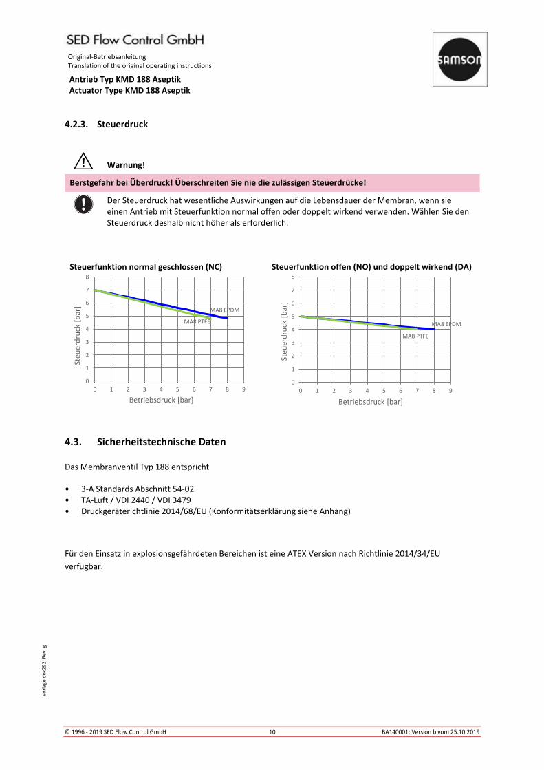
4.2.3. Steuerdruck
Warnung!
Berstgefahr bei Überdruck! Überschreiten Sie nie die zulässigen Steuerdrücke!
Der Steuerdruck hat wesentliche Auswirkungen auf die Lebensdauer der Membran, wenn sie
einen Antrieb mit Steuerfunktion normal offen oder doppelt wirkend verwenden. Wählen Sie den
Steuerdruck deshalb nicht höher als erforderlich.
Steuerfunktion normal geschlossen (NC) Steuerfunktion offen (NO) und doppelt wirkend (DA)
4.3. Sicherheitstechnische Daten
Das Membranventil Typ 188 entspricht
• 3-A Standards Abschnitt 54-02
• TA-Luft / VDI 2440 / VDI 3479
• Druckgeräterichtlinie 2014/68/EU (Konformitätserklärung siehe Anhang)
Für den Einsatz in explosionsgefährdeten Bereichen ist eine ATEX Version nach Richtlinie 2014/34/EU
verfügbar.
MA8 EPDM
MA8 PTFE
0
1
2
3
4
5
6
7
8
0 1 2 3 4 5 6 7 8 9
Ste
ue
rdru
ck [
bar
]
Betriebsdruck [bar]
MA8 EPDM
MA8 PTFE
0
1
2
3
4
5
6
7
8
0 1 2 3 4 5 6 7 8 9
Ste
ue
rdru
ck [
bar
]
Betriebsdruck [bar]
Original-Betriebsanleitung Translation of the original operating instructions
Antrieb Typ KMD 188 Aseptik Actuator Type KMD 188 Aseptik
© 1996 - 2019 SED Flow Control GmbH 11 BA140001; Version b vom 25.10.2019
Vo
rlag
e d
ok2
92
; R
ev.
g
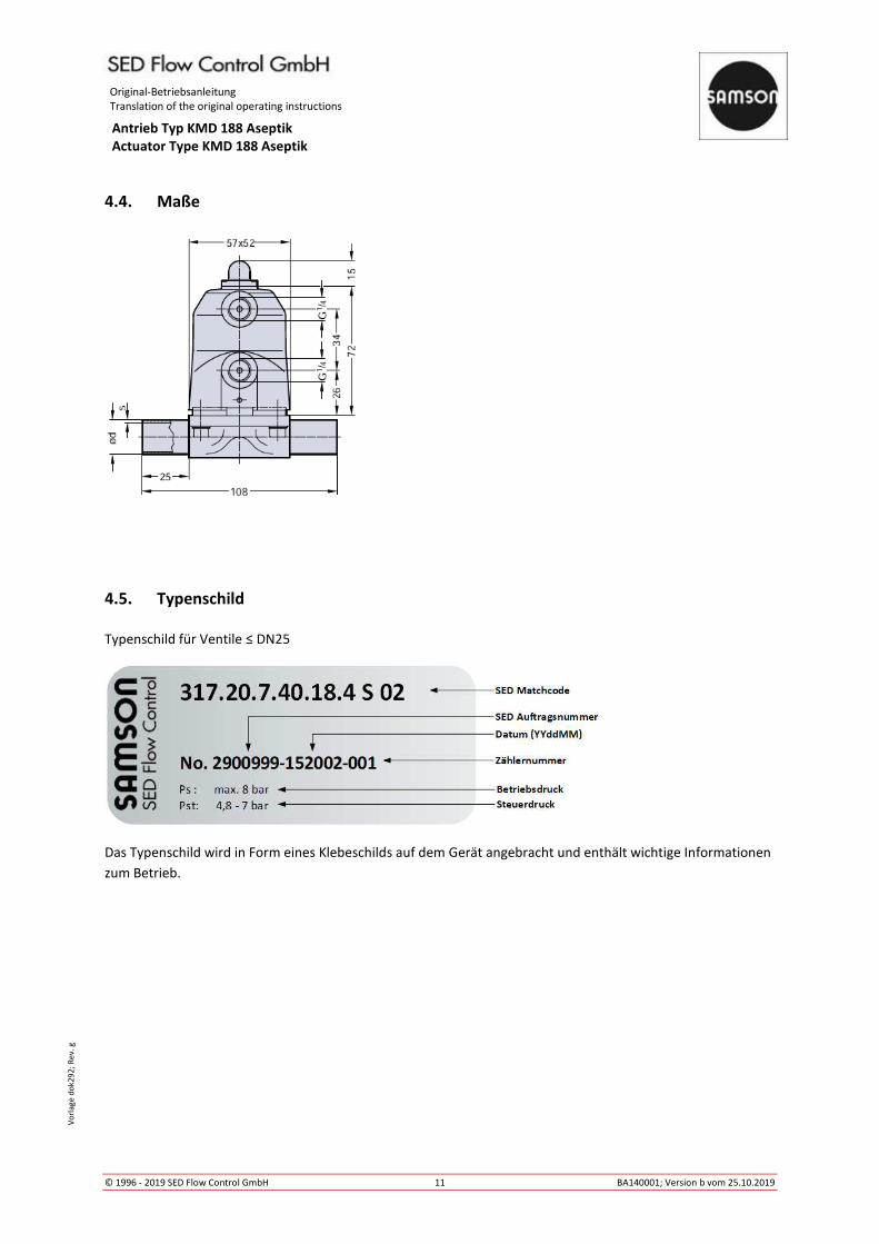
4.4. Maße
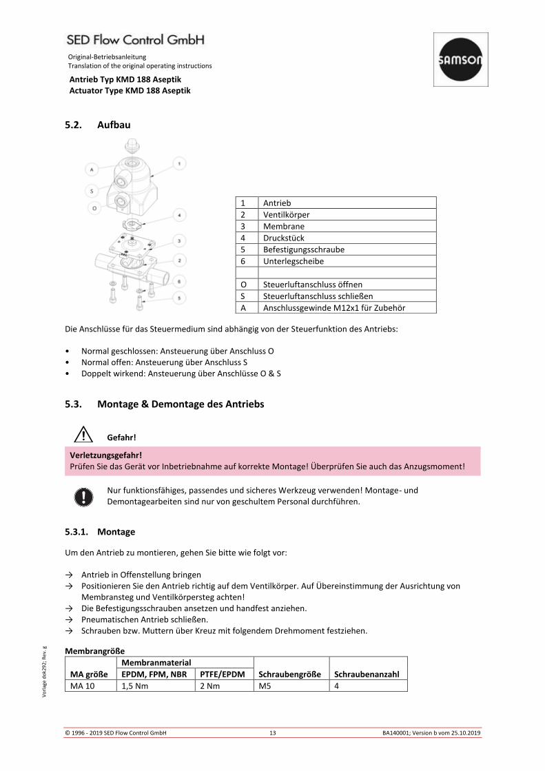
4.5. Typenschild
Typenschild für Ventile ≤ DN25
Das Typenschild wird in Form eines Klebeschilds auf dem Gerät angebracht und enthält wichtige Informationen
zum Betrieb.

Original-Betriebsanleitung Translation of the original operating instructions
Antrieb Typ KMD 188 Aseptik Actuator Type KMD 188 Aseptik
© 1996 - 2019 SED Flow Control GmbH 12 BA140001; Version b vom 25.10.2019
Vo
rlag
e d
ok2
92
; R
ev.
g
5. Installation
Gefahr!
Verletzungsgefahr durch hohen Druck! Druck auf Leitungen und Ventilen kann schwere Verletzungen verursachen! Vor dem Lösen von Leitungen und Ventilen den Druck abschalten und Leitungen entleeren.
Verletzungsgefahr durch Stromschlag! Spannung abschalten und gegen ungewolltes Wiedereinschalten sichern.
Warnung!
Verletzungsgefahr bei unsachgemäßer Montage! Unsachgemäße Montage kann schwere Verletzungen verursachen. Montage darf nur durch autorisiertes Fachpersonal ausgeführt werden.
Geeignetes Werkzeug verwenden.
Anlage gegen ungewolltes Wiedereinschalten sichern! Kontrollierten Anlauf nach Abschaltung gewährleisten!
5.1. Benötigtes Werkzeug
Die benötigten Werkzeuge für die Montage und den Einbau des Geräts sind nicht im Lieferumfang enthalten:
Nur funktionsfähiges, passendes und sicheres Werkzeug verwenden!
Original-Betriebsanleitung Translation of the original operating instructions
Antrieb Typ KMD 188 Aseptik Actuator Type KMD 188 Aseptik
© 1996 - 2019 SED Flow Control GmbH 13 BA140001; Version b vom 25.10.2019
Vo
rlag
e d
ok2
92
; R
ev.
g
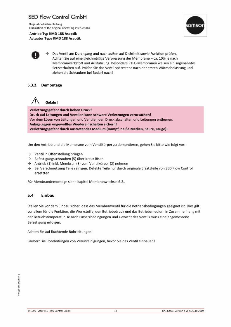
5.2. Aufbau
Die Anschlüsse für das Steuermedium sind abhängig von der Steuerfunktion des Antriebs:
• Normal geschlossen: Ansteuerung über Anschluss O
• Normal offen: Ansteuerung über Anschluss S
• Doppelt wirkend: Ansteuerung über Anschlüsse O & S
5.3. Montage & Demontage des Antriebs
Gefahr!
Verletzungsgefahr! Prüfen Sie das Gerät vor Inbetriebnahme auf korrekte Montage! Überprüfen Sie auch das Anzugsmoment!
Nur funktionsfähiges, passendes und sicheres Werkzeug verwenden! Montage- und
Demontagearbeiten sind nur von geschultem Personal durchführen.
5.3.1. Montage
Um den Antrieb zu montieren, gehen Sie bitte wie folgt vor:
→ Antrieb in Offenstellung bringen
→ Positionieren Sie den Antrieb richtig auf dem Ventilkörper. Auf Übereinstimmung der Ausrichtung von
Membransteg und Ventilkörpersteg achten!
→ Die Befestigungsschrauben ansetzen und handfest anziehen.
→ Pneumatischen Antrieb schließen.
→ Schrauben bzw. Muttern über Kreuz mit folgendem Drehmoment festziehen.
Membrangröße
MA größe
Membranmaterial
Schraubengröße Schraubenanzahl EPDM, FPM, NBR PTFE/EPDM
MA 10 1,5 Nm 2 Nm M5 4
1 Antrieb
2 Ventilkörper
3 Membrane
4 Druckstück
5 Befestigungsschraube
6 Unterlegscheibe
O Steuerluftanschluss öffnen
S Steuerluftanschluss schließen
A Anschlussgewinde M12x1 für Zubehör
O
S
Original-Betriebsanleitung Translation of the original operating instructions
Antrieb Typ KMD 188 Aseptik Actuator Type KMD 188 Aseptik
© 1996 - 2019 SED Flow Control GmbH 14 BA140001; Version b vom 25.10.2019
Vo
rlag
e d
ok2
92
; R
ev.
g
→ Das Ventil am Durchgang und nach außen auf Dichtheit sowie Funktion prüfen.
Achten Sie auf eine gleichmäßige Verpressung der Membrane – ca. 10% je nach
Membranwerkstoff und Ausführung. Besonders PTFE-Membranen weisen ein sogenanntes
Setzverhalten auf. Prüfen Sie das Ventil spätestens nach der ersten Wärmebelastung und
ziehen die Schrauben bei Bedarf nach!
5.3.2. Demontage
Gefahr!
Verletzungsgefahr durch hohen Druck! Druck auf Leitungen und Ventilen kann schwere Verletzungen verursachen! Vor dem Lösen von Leitungen und Ventilen den Druck abschalten und Leitungen entleeren.
Anlage gegen ungewolltes Wiedereinschalten sichern! Verletzungsgefahr durch austretendes Medium (Dampf, heiße Medien, Säure, Lauge)!
Um den Antrieb und die Membrane vom Ventilkörper zu demontieren, gehen Sie bitte wie folgt vor:
→ Ventil in Offenstellung bringen
→ Befestigungsschrauben (5) über Kreuz lösen
→ Antrieb (1) inkl. Membran (3) vom Ventilkörper (2) nehmen
→ Bei Verschmutzung Teile reinigen. Defekte Teile nur durch originale Ersatzteile von SED Flow Control
ersetzten
Für Membrandemontage siehe Kapitel Membranwechsel 6.2..
5.4 Einbau
Stellen Sie vor dem Einbau sicher, dass das Membranventil für die Betriebsbedingungen geeignet ist. Dies gilt
vor allem für die Funktion, die Werkstoffe, den Betriebsdruck und das Betriebsmedium in Zusammenhang mit
der Betriebstemperatur. Je nach Einsatzbedingungen und Gewicht des Ventils muss eine angemessene
Befestigung erfolgen.
Achten Sie auf fluchtende Rohrleitungen!
Säubern sie Rohrleitungen von Verunreinigungen, bevor Sie das Ventil einbauen!

Original-Betriebsanleitung Translation of the original operating instructions
Antrieb Typ KMD 188 Aseptik Actuator Type KMD 188 Aseptik
© 1996 - 2019 SED Flow Control GmbH 15 BA140001; Version b vom 25.10.2019
Vo
rlag
e d
ok2
92
; R
ev.
g
5.4.1. Selbstentleerung 2/2 Wege Ventile für aseptische Anwendungen
Das 2/2 Wege Membranventil kann unabhängig von Lage und Durchflussrichtung eingebaut werden. Bei
horizontalem Einbau in Selbstentleerungsposition ist der Einbauwinkel für das Ventil zu befolgen:
VENTILGRÖSSE SELBSTENTLEERUNGSWINKEL α (Grad) GESCHMIEDET FEINGUSS ISO 1127 DIN 11850 ASME BPE ISO 1127 DIN 11850 ASME BPE
Code 40 Code 41+42 Code 45 Code 40 Code 41+42 Code 45
(mm) (inch) MA DIN11866 DIN11866
DN NPS Code 42 Code 42
8 - 10 26,6 - - 31 - -
10 3/8 10 20,6 - 31,4 20 32 -
15 1/2 10 12,8 17,3 28,8 10,5 16 33
20 - 10 - - 17,4 - 19(*4) 16,5
5.4.2. Anschluss Schweißstutzen
Beachten Sie die in Ihrem Land gültigen Gesetze, Normen und Regelwerke zum Schweißen!
→ Das Ventil muss vor Schweißarbeiten komplett demontiert werden! Siehe Kapitel 5.3.2.
→ Ventilkörper einschweißen und abkühlen lassen. Bei Bedarf auf Selbstentleerungsposition
achten, siehe Kapitel 5.4.1. Oberfläche bei Bedarf durch Schleifen glätten.
→ Antrieb und Membrane auf Ventilkörper montieren, siehe Kapitel 5.3.1.
5.5. Inbetriebnahme
Versichern Sie sich vor Inbetriebnahme von der korrekten Installation. Überprüfen Sie auch die
Dichtheit im Einspannbereich Antrieb – Membrane – Ventilkörper sowie die Funktion. Die
Leitungen für das Steuermedium müssen knickfrei und spannungslos verlegt werden. Achten Sie
auch auf den korrekten Anschluss des Steuermediums, siehe auch Kapitel 5.2.

Original-Betriebsanleitung Translation of the original operating instructions
Antrieb Typ KMD 188 Aseptik Actuator Type KMD 188 Aseptik
© 1996 - 2019 SED Flow Control GmbH 16 BA140001; Version b vom 25.10.2019
Vo
rlag
e d
ok2
92
; R
ev.
g
5.6 Bedienung des Zubehörs
Das Membranventil verfügt serienmäßig über eine optische Stellungsanzeige.
Optische Stellungsanzeige
Die optische Stellungsanzeige gibt die Ventilstellung wieder. So kann erkannt werden, ob das Ventil geöffnet
oder geschlossen ist.
Ventil geschlossen Ventil offen
6. Wartung
Wartungsarbeiten dürfen nur von geschultem Personal durchgeführt werden!
Membranventile sind grundsätzlich wartungsarm. Sie müssen in regelmäßigen Abständen geprüft und gewartet
werden.
Die Abstände der Prüfungen müssen entsprechend der Einsatzbelastungen und der geltenden Regelwerke
festgelegt und entsprechend durchgeführt werden.
Original-Betriebsanleitung Translation of the original operating instructions
Antrieb Typ KMD 188 Aseptik Actuator Type KMD 188 Aseptik
© 1996 - 2019 SED Flow Control GmbH 17 BA140001; Version b vom 25.10.2019
Vo
rlag
e d
ok2
92
; R
ev.
g
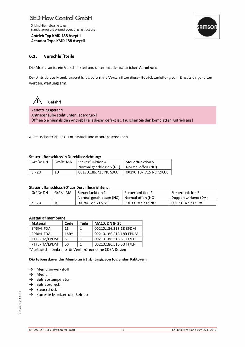
6.1. Verschleißteile
Die Membran ist ein Verschleißteil und unterliegt der natürlichen Abnutzung.
Der Antrieb des Membranventils ist, sofern die Vorschriften dieser Betriebsanleitung zum Einsatz eingehalten
werden, wartungsarm.
Gefahr!
Verletzungsgefahr!
Antriebshaube steht unter Federdruck!
Öffnen Sie niemals den Antrieb! Falls dieser defekt ist, tauschen Sie den kompletten Antrieb aus!
Austauschantrieb, inkl. Druckstück und Montageschrauben
Steuerluftanschluss in Durchflussrichtung:
Größe DN Größe MA Steuerfunktion 4
Normal geschlossen (NC)
Steuerfunktion 5
Normal offen (NO)
8 - 20 10 00190.186.715 NC S900 00190.187.715 NO S9000
Steuerluftanschluss 90° zur Durchflussrichtung:
Größe DN Größe MA Steuerfunktion 1
Normal geschlossen (NC)
Steuerfunktion 2
Normal offen (NO)
Steuerfunktion 3
Doppelt wirkend (DA)
8 - 20 10 00190.186.715 NC 00190.187.715 NO 00190.187.715 DA
Austauschmembrane
Material Code Teile MA10, DN 8- 20
EPDM, FDA 18 1 00210.186.515.18 EPDM
EPDM, FDA 18R* 1 00210.186.515.18R EPDM
PTFE-TM/EPDM 51 1 00210.186.515.51 TF/EP
PTFE-TM/EPDM 50 1 00210.186.515.50 TF/EP
*Austauschmembrane für Ventilkörper ohne CDSA Design
Die Lebensdauer der Membran ist abhängig von folgenden Faktoren:
→ Membranwerkstoff
→ Medium
→ Betriebstemperatur
→ Betriebsdruck
→ Steuerdruck
→ Korrekte Montage und Betrieb
Original-Betriebsanleitung Translation of the original operating instructions
Antrieb Typ KMD 188 Aseptik Actuator Type KMD 188 Aseptik
© 1996 - 2019 SED Flow Control GmbH 18 BA140001; Version b vom 25.10.2019
Vo
rlag
e d
ok2
92
; R
ev.
g
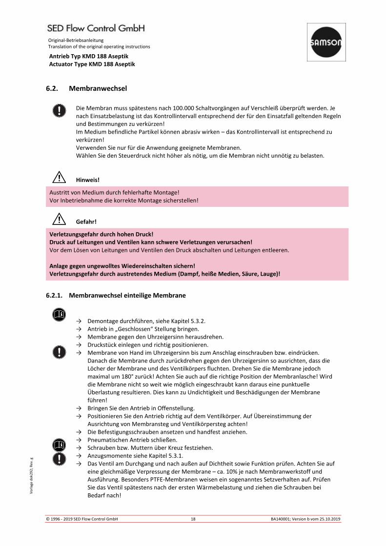
6.2. Membranwechsel
Die Membran muss spätestens nach 100.000 Schaltvorgängen auf Verschleiß überprüft werden. Je
nach Einsatzbelastung ist das Kontrollintervall entsprechend der für den Einsatzfall geltenden Regeln
und Bestimmungen zu verkürzen!
Im Medium befindliche Partikel können abrasiv wirken – das Kontrollintervall ist entsprechend zu
verkürzen!
Verwenden Sie nur für die Anwendung geeignete Membranen.
Wählen Sie den Steuerdruck nicht höher als nötig, um die Membran nicht unnötig zu belasten.
Hinweis!
Austritt von Medium durch fehlerhafte Montage!
Vor Inbetriebnahme die korrekte Montage sicherstellen!
Gefahr!
Verletzungsgefahr durch hohen Druck! Druck auf Leitungen und Ventilen kann schwere Verletzungen verursachen! Vor dem Lösen von Leitungen und Ventilen den Druck abschalten und Leitungen entleeren.
Anlage gegen ungewolltes Wiedereinschalten sichern! Verletzungsgefahr durch austretendes Medium (Dampf, heiße Medien, Säure, Lauge)!
6.2.1. Membranwechsel einteilige Membrane
→ Demontage durchführen, siehe Kapitel 5.3.2.
→ Antrieb in „Geschlossen“ Stellung bringen. → Membrane gegen den Uhrzeigersinn herausdrehen.
→ Druckstück einlegen und richtig positionieren.
→ Membrane von Hand im Uhrzeigersinn bis zum Anschlag einschrauben bzw. eindrücken.
Danach die Membrane durch zurückdrehen gegen den Uhrzeigersinn so ausrichten, dass die
Löcher der Membrane und des Ventilkörpers fluchten. Drehen Sie die Membrane jedoch
maximal um 180° zurück! Achten Sie auch auf die richtige Position der Membranlasche! Wird
die Membrane nicht so weit wie möglich eingeschraubt kann daraus eine punktuelle
Überlastung resultieren. Dies kann zu Undichtigkeit und Beschädigungen der Membrane
führen!
→ Bringen Sie den Antrieb in Offenstellung.
→ Positionieren Sie den Antrieb richtig auf dem Ventilkörper. Auf Übereinstimmung der
Ausrichtung von Membransteg und Ventilkörpersteg achten!
→ Die Befestigungsschrauben ansetzen und handfest anziehen.
→ Pneumatischen Antrieb schließen.
→ Schrauben bzw. Muttern über Kreuz festziehen.
→ Anzugsmomente siehe Kapitel 5.3.1.
→ Das Ventil am Durchgang und nach außen auf Dichtheit sowie Funktion prüfen. Achten Sie auf
eine gleichmäßige Verpressung der Membrane – ca. 10% je nach Membranwerkstoff und
Ausführung. Besonders PTFE-Membranen weisen ein sogenanntes Setzverhalten auf. Prüfen
Sie das Ventil spätestens nach der ersten Wärmebelastung und ziehen die Schrauben bei
Bedarf nach!

Original-Betriebsanleitung Translation of the original operating instructions
Antrieb Typ KMD 188 Aseptik Actuator Type KMD 188 Aseptik
© 1996 - 2019 SED Flow Control GmbH 19 BA140001; Version b vom 25.10.2019
Vo
rlag
e d
ok2
92
; R
ev.
g
6.3. Reinigung
Zur äußeren Reinigung können handelsübliche Reinigungsmittel verwendet werden. Prüfen Sie vor dem Einsatz
die Chemische Beständigkeit aller im Ventil verwendeten Materialien, die mit dem Reinigungsmittel in Kontakt
kommen.
Prüfen Sie vor einem Sterilisationsvorgang, ob das Ventil für das jeweilige Verfahren geeignet ist.
7. Zubehör
Passendes, funktionales Zubehör finden Sie unter www.sed-flowcontrol.com oder kontaktieren Sie uns.

Original-Betriebsanleitung Translation of the original operating instructions
Antrieb Typ KMD 188 Aseptik Actuator Type KMD 188 Aseptik
© 1996 - 2019 SED Flow Control GmbH 20 BA140001; Version b vom 25.10.2019
Vo
rlag
e d
ok2
92
; R
ev.
g
8. Fehlerbehebung
Störungsbild Mögliche Ursache Behebung
Ventil schließt nicht oder nicht
vollständig
Steuerdruck zu gering (Bei
Steuerfunktion NO & DA)
Ventil mit Druck gemäß Spezifikation
betreiben, siehe Kapitel 4.2.3.
Mediumsdruck zu hoch Maximalen Betriebsdruck beachten, siehe
Kapitel 4.2.2.
Steuerluftanschluss vertauscht Steuerluftanschluss prüfen, siehe Kapitel
5.2.
Steuerluft nicht angeschlossen Steuerluft anschließen
Pilotventil defekt Pilotventil auf Funktion prüfen
Fremdkörper zwischen Membran
und Ventilsteg
Ventil demontieren, Fremdkörper entfernen
und Bauteile auf Beschädigung prüfen.
Siehe Kapitel 5.3.ff
Membrane defekt Membran austauschen, siehe Kapitel 6.2.ff
Feder im Antrieb defekt (Bei
Steuerfunktion NC)
Antrieb austauschen, siehe Kapitel 5.3.ff
Ventil öffnet nicht oder nicht
vollständig
Steuerdruck zu gering (Bei
Steuerfunktion NC)
Ventil mit Druck gemäß Spezifikation
betreiben, siehe Kapitel 4.2.3.
Steuerluftanschluss vertauscht Steuerluftanschluss prüfen, siehe Kapitel
5.2.
Steuerluft nicht angeschlossen Steuerluft anschließen
Pilotventil defekt Pilotventil auf Funktion prüfen
Membrane falsch montiert Antrieb demontieren und Membrane
korrekt montieren, siehe Kapitel 6.2.ff
Feder im Antrieb defekt (Bei
Steuerfunktion NO)
Antrieb austauschen, siehe Kapitel 5.3.ff
Betriebsmedium entweicht am
Membranflansch
Membrane falsch montiert Antrieb demontieren und Membrane
korrekt montieren, siehe Kapitel 6.2.ff
Anzugsmoment der
Verschraubung von Antrieb und
Ventilkörper zu niedrig
Verschraubung von Antrieb und
Ventilkörper prüfen, siehe Kapitel 5.3.1.
Membrane defekt Membran austauschen, siehe Kapitel 6.2.ff
Antrieb defekt Antrieb austauschen, siehe Kapitel 5.3.ff
Ventilkörper defekt Ventilkörper austauschen
Mediumsdruck zu hoch Maximalen Betriebsdruck beachten, siehe
Kapitel 4.2.2.
Betriebstemperatur zu hoch Maximale Betriebstemperatur beachten,
siehe Kapitel 4.2.1.
Betriebsmedium entweicht am
Rohranschluss
Dichtung / Dichtmittel defekt Dichtung / Dichtmittel austauschen
Unsachgemäßer Einbau Ventilkörper korrekt einbauen
Verschraubung oder
Gewindeanschluss lose
Verschraubung oder Gewindeanschluss
nachziehen
Betriebsmedium entweicht
durch Ventilkörper
Ventilkörper defekt Ventilkörper austauschen
Steuermedium entweicht an
Leckagebohrung
Spindelabdichtung defekt Antrieb austauschen, siehe Kapitel 5.3.ff
und Steuerluft auf Verschmutzung prüfen
Steuermedium entweicht aus
Steuerluftanschluss öffnen (bei
Steuerfunktion NC) bzw.
schließen (bei Steuerfunktion
NO)
Steuermembrane bzw.
Kolbennutring defekt
Antrieb austauschen, siehe Kapitel 5.3.ff

Original-Betriebsanleitung Translation of the original operating instructions
Antrieb Typ KMD 188 Aseptik Actuator Type KMD 188 Aseptik
© 1996 - 2019 SED Flow Control GmbH 21 BA140001; Version b vom 25.10.2019
Vo
rlag
e d
ok2
92
; R
ev.
g
9. EG Konformitätserklärung
Original-Betriebsanleitung Translation of the original operating instructions
Antrieb Typ KMD 188 Aseptik Actuator Type KMD 188 Aseptik
© 1996 - 2019 SED Flow Control GmbH 22 BA140001; Version b vom 25.10.2019
Vo
rlag
e d
ok2
92
; R
ev.
g
1. Introduction
In case you have any queries about the device, please contact our customer services stating the serial number:
SED Flow Control GmbH Am Schafbaum 2
D-74906 Bad Rappenau
PO-Box 1306
D-74900 Bad Rappenau
Phone: +49(0)7264/921-0
Fax: +49(0)7264/921-21
E-Mail: [email protected]
Web: www.sed-flowcontrol.com
These operating instructions describe the technical status of the device at delivery.
It is valid for standard versions. For special versions please contact our customer services.
Any subsequent changes at the device are not considered in these operating instructions.
© 2019
The present operating instructions document is protected by copyright. Without written approval by the
manufacturer it may not be translated, reproduced (mechanically or electronically) or disclosed to third parties,
either in full or in parts.
The German version of these operating instructions is deciding in case of doubt, misunderstandings or
translation mistakes!
Creation date: 25.10.2019
Revision: b
Printed in Germany
Original-Betriebsanleitung Translation of the original operating instructions
Antrieb Typ KMD 188 Aseptik Actuator Type KMD 188 Aseptik
© 1996 - 2019 SED Flow Control GmbH 23 BA140001; Version b vom 25.10.2019
Vo
rlag
e d
ok2
92
; R
ev.
g
1.1. Information about the operating instructions
Safe operation The operating instructions contain important information for safe and correct installation of the device.
Compliance with that helps preventing hazards, avoiding repair costs and downtime, and increasing reliability
and operating life of the device.
Target groups
The contents of these operating instructions are intended for installation and maintenance staff.
Reading the operating instructions All persons who work at the device must read the operating instructions in order to be familiar with correct
handling and operation. The operating instructions contain important safety information! Non-compliance with
such information may cause hazardous situations. The operating instructions must be read and understood.
Copyright The present operating instructions document is protected by copyright. Without written approval by SED Flow
Control GmbH it must not be reproduced, distributed, or unauthorizedly used for competitive purposes, either
in full or in parts.
All rights for drawings and other documents and any power of disposal are solely with SED Flow Control GmbH;
this also applies for cases of application for intellectual property rights.
Declaration of conformity The device complies with the basic requirements of the applicable European directives. Conformity was
proved.
Technical changes We constantly strive for further development and improvement of our devices. The data contained in this
edition correspond to the state of the art at the time of printing. All technical details with regard to information
and figures within the operating instructions are subject to change.
Warranty The present printed document does not contain any guarantee commitments. For that purpose, please see our
general terms and conditions of delivery and payment. The prerequisite for statutory warranty is the intended
use of the device in compliance with the specified operating conditions.
The warranty only applies to absence of defectiveness of the device and its components. No liability will be
assumed for consequential damage occurring through failure or malfunction of the device, irrespective of their
nature.
Information on the internet Instructions and data sheets for the device are provided on the internet at:
www.sed-flowcontrol.com

Original-Betriebsanleitung Translation of the original operating instructions
Antrieb Typ KMD 188 Aseptik Actuator Type KMD 188 Aseptik
© 1996 - 2019 SED Flow Control GmbH 24 BA140001; Version b vom 25.10.2019
Vo
rlag
e d
ok2
92
; R
ev.
g
2. Safety
2.1. Safety Information
Warning!
The operating instructions contain important safety information! Non-compliance with such information may cause hazardous situations.
The operating instructions must be read and understood.
2.2. Hazard classification
Danger!
Indicates imminent danger! Non-compliance will result in death or severe injuries.
Warning!
Indicates a potentially hazardous situation! Non-compliance may result in severe injuries.
Attention!
Indicates a possible hazard! Non-compliance may result in moderate or slight injuries.
Notice!
Warning from property damage! Non-compliance may cause damage to the device or the facility.
Indicates important additional information, tips and recommendations
Indicates important reference to information in these operating instructions and in other
documentation.
→ Indicates an operating step that must be performed.

Original-Betriebsanleitung Translation of the original operating instructions
Antrieb Typ KMD 188 Aseptik Actuator Type KMD 188 Aseptik
© 1996 - 2019 SED Flow Control GmbH 25 BA140001; Version b vom 25.10.2019
Vo
rlag
e d
ok2
92
; R
ev.
g
2.3. Intended use
Diaphragm valves are made to be assembled in pipelines and are used to regulate media from high purity to
the point of contaminated or even abrasive.
Use these devices only with media, the body and the sealing is consistent for.
Intended use also includes compliance with the installation and maintenance conditions prescribed by the
manufacturer and the state of art.
Any other use beyond the stated purpose is regarded as not as intended. The manufacturer is not liable for
any damage resulting thereof; the entire risk shall be with the user.
2.4. Misuse
• Do not supply the system with flammable or aggressive medias.
• Do not apply mechanical loads on the housing (e.g. positioning of objects on the device, using it as a step).
• Do not carry out any external modifications on the housings of devices. Do not paint any parts of the
housing.
• Use the device only with components or spare parts, which are approved from SED Flow Control GmbH.
• The standard version of the Seat valve must not be used in potentially explosive areas. For this purpose
please use the suitable version and use it only in approved regions!
2.5. General safety provisions
• The operating instructions by the manufacturer are binding for installation, programming, maintenance
and transport.
• It is the operator‘s responsibility to complement the safety provisions by special instructions specific for
local operating conditions, if required.
• The operating instructions and all safety-relevant rules and regulations must be kept in a safe place.
• The operating instructions and safety information must be available in full and in easily legible condition.
Accident prevention rules In addition to the operating instructions and the binding rules and regulations for accident prevention
applicable in the country of use and the place of operation, the approved technical rules for safe and
professional working must be observed.
Before beginning with your work Before beginning with your work, please obtain information about first-aid and rescue options (emergency,
doctor, fire- and rescue services). Please obtain information about locations and operation of fire extinguishers
and about fire alarm and firefighting options on site. Retain the unit against inadvertent operation.
During work During operation, wear suitable work clothes.
Do not carry out activities that may impair safety.
Only operate the device in safe and functional condition.
Provisions for protection of the environment For any work at or with the device, the provisions for environmental protection must be complied with.

Original-Betriebsanleitung Translation of the original operating instructions
Antrieb Typ KMD 188 Aseptik Actuator Type KMD 188 Aseptik
© 1996 - 2019 SED Flow Control GmbH 26 BA140001; Version b vom 25.10.2019
Vo
rlag
e d
ok2
92
; R
ev.
g
2.6. Residual risks
Danger!
Danger of injury through high pressure! Pressure acting on lines and valves may cause severe injuries! Before disconnecting any lines and valves, the pressure must be switched off and the lines must be vented. At no time overstep the maximum operation or control pressure! Danger through electric voltage! Electrical voltage may cause severe injuries or death! Before working at the facility, voltage must be switched off and secured against unauthorized activation! Attend to valid accident prevention and safety guidelines for electrical devices!
Warning!
Protect the facility from inadvertent operation! After shutdown the facility a controlled restart must be guaranteed!
Attention!
Danger trough hot device surface while continuous operation! Hot device surface may cause burning - or danger of fire!
Keep the device away from easy burning materials and do not touch with bare hands!
2.7. Responsibilities of the operator
Devices that are not in unobjectionable condition may cause personal injury and property damage.
It is the operator’s responsibility to only operate the device in unobjectionable condition. Hazard zones that occur between the device and any equipment on the customer’s site must be secured by the operator. The operator must ensure sufficient illumination during work at the device.
2.7.1 Appointment and instruction of responsible persons
• Only employ staff who has received safety instructions.
• Responsibilities and competencies of staff with regard to installation, programming and maintenance must
be clearly defined.
• Regularly monitor the staff for safe and responsible working methods and compliance with the operating
instructions
2.7.2. Information obligation
It is the obligation of the operator of the device to make these operating instructions available to all persons
who work with the device at any time.
Before use of the device, all persons must have read and fully understood the operating instructions.
Original-Betriebsanleitung Translation of the original operating instructions
Antrieb Typ KMD 188 Aseptik Actuator Type KMD 188 Aseptik
© 1996 - 2019 SED Flow Control GmbH 27 BA140001; Version b vom 25.10.2019
Vo
rlag
e d
ok2
92
; R
ev.
g
2.8. Description of target groups
The contents of these operating instructions are intended for various target groups. The level of
knowledge/information the respective target group must have is defined below.
All target groups must have read and fully understood the contents of these operating instructions.
Installation, programming and maintenance staff must
• Be 18 years of age;
• Have profound education and professional training;
• Be trained with regard to conduct in case of a fault.
3. Transport / Storage / Disposal
3.1. Delivery
3.1.1. Scope of delivery
Immediately after receipt of the delivery, please verify that the contents are not damaged and the type and
scope of the delivery complies with the data stated on the delivery note.
By checking the order number, please verify that the goods received comply with the versions you ordered.
In case of irregularities, please contact us immediately.
3.1.2. Notification about damage
Damage resulting from inadequate packaging or during transport must be communicated to the shipping
company, the insurance, and the supplier immediately after delivery of the consignment.
3.2. Transport
Notice!
If the guidelines are not reserved, the device may be damaged!
The device must be transported in impact-resistant packaging.
During transport, the device must be protected against humidity and dirt.
The approved ambient temperature of –10 °C to +55 °C must not be exceeded through the impact of heat or
cold.

Original-Betriebsanleitung Translation of the original operating instructions
Antrieb Typ KMD 188 Aseptik Actuator Type KMD 188 Aseptik
© 1996 - 2019 SED Flow Control GmbH 28 BA140001; Version b vom 25.10.2019
Vo
rlag
e d
ok2
92
; R
ev.
g
3.3. Storage
Notice!
If the guidelines are not reserved, the device may be damaged.
Danger!
Danger of injury after reassembly! Please check, if there are any damages and ensure, that the mounting is correct, especially loosened
erection screws!
In order to keep a device that is not used over a longer period functional, a few items must be considered:
• Please store the device in its original packaging.
• The storage location must be dry and clean.
• Storage temperature must be between –10 °C and +55 °C
• Lock up the control air ports with protecting caps.
• Secure the device against unauthorized operation.
• Please do not store in abrasive surrounding area.
3.4. Disposal
Protect the environment! The individual components and the packaging must be properly disposed of according to the types of materials.
Please note the current rules for waste disposal!
Notice!
Please check all media contacting parts, if they are contaminated and dispose these if necessary according to the current rules of waste disposal and environmental regulations!

Original-Betriebsanleitung Translation of the original operating instructions
Antrieb Typ KMD 188 Aseptik Actuator Type KMD 188 Aseptik
© 1996 - 2019 SED Flow Control GmbH 29 BA140001; Version b vom 25.10.2019
Vo
rlag
e d
ok2
92
; R
ev.
g
4. Technical Data
4.1. General technical data
Size DN 8 – DN 20
Diaphragm Size MA MA 10
Available control functions (Cf.) Normally closed, Cf.1 & 4
Normally open, Cf.2 & 5
Double acting, Cf. 3
Orientation control air connection Cf. 4, 5, in flow direction,
Cf. 1, 2, 3, 90° to flow direction
Actuator suitable for valve bodies Two-Way bodies
Welded valve configuration
End connection valve body Butt weld ends acc. DIN 11866
Row A (formerly DIN 11850 Row1 & 2)
Row B (formerly ISO 1127)
Row C (formerly ASME BPE / ASTM 269)
BS O.D: 4825; SMS 3008, JIS G 3447
Clamps, flanges and threads acc. Customer specifications or
customer order
Control air connection Threaded socket G1/4“
Control media Filtered, lubricated or non-lubricated air
Neutral, gaseous fluids
Dust- and oil content acc. DIN ISO 85731 class 4
Max. temperature 40°C
Material actuator housing Version S: PP GF
Version HS: IXEF
Material valve body 1.4435 / 316L Investment cast
1.4435 / 316L forged
1.4435 / 316L forged Fe < 0,5% (Basler Norm)
Material diaphragm EPDM, PTFE-TM / EPDM, FPM, NBR,
Installation position Any, actuator up preferred (except tank valve)
Actuator capacity
Diaphragm Size MA Control function 1&4: Control function 2&5
10 0,027 Nl 0,027 Nl
Nl: Norm litre, volume at atmospherically pressure
For Cf. 3&6 see actuator capacity of Cf.1&4 for opening and Cf.2&5 for closing.

Original-Betriebsanleitung Translation of the original operating instructions
Antrieb Typ KMD 188 Aseptik Actuator Type KMD 188 Aseptik
© 1996 - 2019 SED Flow Control GmbH 30 BA140001; Version b vom 25.10.2019
Vo
rlag
e d
ok2
92
; R
ev.
g
4.2. Operating conditions
4.2.1. Operating temperatures
Warning!
Do not exceed or undershoot the permitted temperatures!
The permissible temperatures are dependent on the used materials. Please pay attention to the lowest
permissible temperature. For high temperatures, the maximum possible operating pressure can decrease!
Permissible media temperature for actuators
Version S: PP GF up to max. 80°C
Version HS: IXEF up to max. 150°C
Permissible temperature for diaphragms
Diaphragm material Code Media temperature
Sterilizations temperature Min. Max.
EPDM 18 -10 °C 90 °C 150 °C, 60 min
EPDM 18R -10 °C 90 °C 150 °C, 60 min
FPM 2 -10 °C 90 °C Not suitable
NBR 4 -10 °C 90 °C Not suitable
PTFE-TM / EPDM 30 -10 °C 90 °C 150 °C, 60 min
PTFE-TM / EPDM 50 -10 °C 90 °C 150 °C, 60 min
PTFE-TM / EPDM 51 -10 °C 90 °C 150 °C, 60 min
Permissible temperature for valve bodies
Material Media temperature
Min. Max.
Stainless Steel -10°C 150°C
4.2.2. Operating pressure
Warning!
Danger of bursting at excess pressure! Do not exceed the permitted operating pressure!
Maximal permissible pressure, unidirectional, static pressure
Membrane MA 10
DN 8 - 20
EPDM, FPM, NBR 8 bar
PTFE-TM / EPDM 7 bar

Original-Betriebsanleitung Translation of the original operating instructions
Antrieb Typ KMD 188 Aseptik Actuator Type KMD 188 Aseptik
© 1996 - 2019 SED Flow Control GmbH 31 BA140001; Version b vom 25.10.2019
Vo
rlag
e d
ok2
92
; R
ev.
g
4.2.3. Control pressure
Warning!
Danger of bursting at excess pressure! Do not exceed the permitted operating pressure!
The control pressure has a significant impact on the lifetime of the diaphragm if you use an
actuator with control function normally open or double-acting. Therefore do not use a higher
control pressure as necessary.
Control function normally closed (NC) Control function open (NO) and double acting (DA)
4.3. Safety related data
The diaphragm valve type 188 is conforming to:
• 3-A Standard Section 54-02
• TA-Luft / VDI 2440 / VDI 3479
• Pressure Equipment Directive 2014/68/EU (see attachment for declaration of conformity)
For use in explosion-risk areas a special ATEX version acc. guideline 2014/34/EU is available
MA8 EPDM
MA8 PTFE
0
1
2
3
4
5
6
7
8
0 1 2 3 4 5 6 7 8 9
Co
ntr
ol p
ress
ure
[b
ar]
Working pressure [bar]
MA8 EPDM
MA8 PTFE
0
1
2
3
4
5
6
7
8
0 1 2 3 4 5 6 7 8 9
Co
ntr
ol p
ress
ure
[b
ar]
Working pressure [bar]
Original-Betriebsanleitung Translation of the original operating instructions
Antrieb Typ KMD 188 Aseptik Actuator Type KMD 188 Aseptik
© 1996 - 2019 SED Flow Control GmbH 32 BA140001; Version b vom 25.10.2019
Vo
rlag
e d
ok2
92
; R
ev.
g
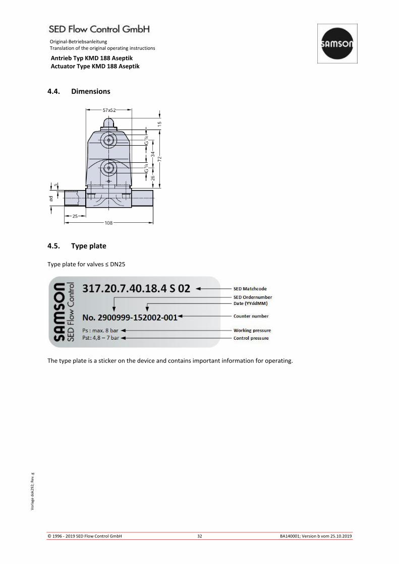
4.4. Dimensions
4.5. Type plate
Type plate for valves ≤ DN25
The type plate is a sticker on the device and contains important information for operating.

Original-Betriebsanleitung Translation of the original operating instructions
Antrieb Typ KMD 188 Aseptik Actuator Type KMD 188 Aseptik
© 1996 - 2019 SED Flow Control GmbH 33 BA140001; Version b vom 25.10.2019
Vo
rlag
e d
ok2
92
; R
ev.
g
5. Installation
Danger!
Danger of injury through high pressure! Pressure acting on lines and valves may cause severe injuries! Before disconnecting any lines and valves, the pressure must be switched off and the lines must be vented.
Danger of injury through electric shock! Shut off current and secure against unauthorized activation.
Warning!
Danger of injury in case of incorrect assembly! Incorrect assembly may cause severe injuries. Assembly and installation must only be performed by authorized expert staff.
Secure plant against unauthorized activation! Guarantee controlled restart after shut down!
5.1. Tools required
The tools required for mounting and installation of the device are not included in the scope of delivery:
Only use functional, suitable and safe tools!

Original-Betriebsanleitung Translation of the original operating instructions
Antrieb Typ KMD 188 Aseptik Actuator Type KMD 188 Aseptik
© 1996 - 2019 SED Flow Control GmbH 34 BA140001; Version b vom 25.10.2019
Vo
rlag
e d
ok2
92
; R
ev.
g
5.2. Structure
The control air connections are dependent on the control function of the actuator.
• Normally closed: Actuated by port O
• Normally open: Actuated by port S
• Double acting: Actuated by port O & S
5.3. Assembly & disassembly of the actuator
Danger!
Danger of injury! Check the device for correct assembly before implementation! Also check the tightening torque!
Only use functional, suitable and safe tools! Assembly and disassembly must only be performed by
authorized expert staff.
5.3.1. Assembly
For assembly of the actuator, proceed as described following:
→ Open the actuator.
→ Place the actuator properly on the valve body. Take care for correct orientation of the diaphragm weir and
valve body weir.
→ Place bolts and screw in hand-tight.
→ Close pneumatic operated actuator or respectively close manual actuator by 80%.
→ Fasten bolts or nuts crosswise with following tightening torque:
Diaphragm size
MA size
Diaphragm material
Bolt size Quantity bolt EPDM, FPM, NBR PTFE/EPDM
MA 10 1,5 Nm 2 Nm M5 4
1 Actuator
2 Valve body
3 Diaphragm
4 Compressor
5 Bolt
6 Washer
O Control air connection open
S Control air connection close
A Assembly thread M12x1 for accessories
O
S

Original-Betriebsanleitung Translation of the original operating instructions
Antrieb Typ KMD 188 Aseptik Actuator Type KMD 188 Aseptik
© 1996 - 2019 SED Flow Control GmbH 35 BA140001; Version b vom 25.10.2019
Vo
rlag
e d
ok2
92
; R
ev.
g
→ Check the valve for function and tightness
Take care for simultaneous compression of the diaphragm – about 10%, depending on
diaphragm material and version. Especially PTFE-diaphragms have a setting behaviour. Check
the valve after the first thermal load latest and re-tighten the bolts if necessary.
5.3.2. Disassembly
Danger!
Danger of injury trough high pressure! Pressure acting on lines and valves may cause severe injuries! Before disconnection any lines and valves, the pressure must be switched off and the lines must be vented.
Secure plant against unauthorized activation! Danger of injury trough media leakage (steam, hot medias, acid, lye)!
For disassembly of the actuator and diaphragm from the valve body proceed as following:
→ Open the valve
→ Loosen screw (5) crosswise
→ Remove actuator (1) incl. diaphragm (3) from valve body (2)
→ If parts are dirty, clean them. Defect parts have to be replaced by original spare parts from SED Flow
Control.
For diaphragm disassembly, see chapter Diaphragm change 6.2.
5.4 Installation
Before installation, ensure that the diaphragm valve is suitable for the operating conditions.
These include function, materials, operating pressure und working media in connection with operating
temperature. Depending on the operating conditions and weight of the valve a suitable fixture has to be
applied.
Take also care for aligning pipes.
Clean pipes before installation.

Original-Betriebsanleitung Translation of the original operating instructions
Antrieb Typ KMD 188 Aseptik Actuator Type KMD 188 Aseptik
© 1996 - 2019 SED Flow Control GmbH 36 BA140001; Version b vom 25.10.2019
Vo
rlag
e d
ok2
92
; R
ev.
g
5.4.1. Self-draining of 2/2 way valves for aseptic applications
The 2/2 way diaphragm valve can be installed independent of position and flow direction. For horizontal
installation in self-draining position, the self-draining angle has to be followed:
VALVE SIZE SELF DRAINING ANGLE α (Degree) FORGED BODIES INVESTMENT CAST BODIES ISO 1127 DIN 11850 ASME BPE ISO 1127 DIN 11850 ASME BPE
Code 40 Code 41+42 Code 45 Code 40 Code 41+42 Code 45
(mm) (inch) MA DIN11866 DIN11866
DN NPS Code 42 Code 42
8 - 10 26,6 - - 31 - -
10 3/8 10 20,6 - 31,4 20 32 -
15 1/2 10 12,8 17,3 28,8 10,5 16 33
20 - 10 - - 17,4 - 19(*4) 16,5
5.4.2. Connection butt weld ends
Follow the laws, directives and regulations for welding which are valid in your country.
→ Disassemble the valve before welding. See chapter 5.3.2.
→ Weld in valve body and cool down. If necessary, weld in in self-draining position, see chapter
5.4.1. Polish surface if needed.
→ Assemble actuator and diaphragm on valve body, see chapter 5.3.1.
5.5. Implementation
Ensure correct installation before implementation. Check tightness in clamping area of actuator,
diaphragm and valve body. Also check the valve for function. Control air lines have to be installed
without kinks and stress less. Take care for correct connection of control air, see chapter 5.2.

Original-Betriebsanleitung Translation of the original operating instructions
Antrieb Typ KMD 188 Aseptik Actuator Type KMD 188 Aseptik
© 1996 - 2019 SED Flow Control GmbH 37 BA140001; Version b vom 25.10.2019
Vo
rlag
e d
ok2
92
; R
ev.
g
5.6. Handling of the accessories
The diaphragm valve features an optical position indicator as standard.
Optical position indicator
The optical position indicator shows the actual valve position. Thus, it can be recognized whether the valve is
open- or closed.
Valve closed Valve open
6. Maintenance
Maintenance is only allowed to be carried out by trained staff.
Diaphragm valves are low-maintenance parts. They have to be checked and maintained periodically. These
periods are depending on working load and have to be defined according to valid rules.
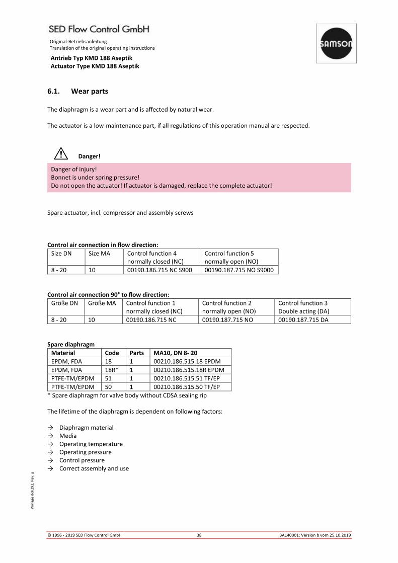
Original-Betriebsanleitung Translation of the original operating instructions
Antrieb Typ KMD 188 Aseptik Actuator Type KMD 188 Aseptik
© 1996 - 2019 SED Flow Control GmbH 38 BA140001; Version b vom 25.10.2019
Vo
rlag
e d
ok2
92
; R
ev.
g
6.1. Wear parts
The diaphragm is a wear part and is affected by natural wear.
The actuator is a low-maintenance part, if all regulations of this operation manual are respected.
Danger!
Danger of injury!
Bonnet is under spring pressure!
Do not open the actuator! If actuator is damaged, replace the complete actuator!
Spare actuator, incl. compressor and assembly screws
Control air connection in flow direction:
Size DN Size MA Control function 4
normally closed (NC)
Control function 5
normally open (NO)
8 - 20 10 00190.186.715 NC S900 00190.187.715 NO S9000
Control air connection 90° to flow direction:
Größe DN Größe MA Control function 1
normally closed (NC)
Control function 2
normally open (NO)
Control function 3
Double acting (DA)
8 - 20 10 00190.186.715 NC 00190.187.715 NO 00190.187.715 DA
Spare diaphragm
Material Code Parts MA10, DN 8- 20
EPDM, FDA 18 1 00210.186.515.18 EPDM
EPDM, FDA 18R* 1 00210.186.515.18R EPDM
PTFE-TM/EPDM 51 1 00210.186.515.51 TF/EP
PTFE-TM/EPDM 50 1 00210.186.515.50 TF/EP
* Spare diaphragm for valve body without CDSA sealing rip
The lifetime of the diaphragm is dependent on following factors:
→ Diaphragm material
→ Media
→ Operating temperature
→ Operating pressure
→ Control pressure
→ Correct assembly and use

Original-Betriebsanleitung Translation of the original operating instructions
Antrieb Typ KMD 188 Aseptik Actuator Type KMD 188 Aseptik
© 1996 - 2019 SED Flow Control GmbH 39 BA140001; Version b vom 25.10.2019
Vo
rlag
e d
ok2
92
; R
ev.
g
6.2. Diaphragm change
The diaphragm has to be controlled for wear after max. 100.000 switching operations. Depending
on working load, the control period has to be reduced according to valid regulations and rules.
Particles in the working media can be abrasive – reduce control period accordingly.
Only use diaphragms which are suitable for your application.
Don’t use higher control pressure than necessary. This helps to save the diaphragm.
Note!
Media leakage by wrong assembly!
Ensure correct assembly before start up!
Danger!
Danger of injury through high pressure! Pressure acting on lines and valves may cause severe injuries! Before disconnecting any lines and valves, the pressure must be switched off and the lines must be vented.
Protect the facility from inadvertent operation! Danger through media leakage (steam, hot media, acid, lye)
6.2.1. Change of one-piece diaphragms
→ Disassemble valve, see chapter 5.3.2.
→ Bring valve in close position.
→ Screw out diaphragm anticlockwise.
→ Insert compressor and position it correctly.
→ Screw in diaphragm by hand up to the stop or respectively plug it in. Then position diaphragm
by turning it back anticlockwise in a way that the wholes of the diaphragm and valve body fit
together. Attention! Do not turn back more than 180°! Also take care for correct position of
the diaphragm flap. If the diaphragm isn’t assembled correctly, point loading can occur! This
can lead to leakage and damage of the diaphragm.
→ Bring valve in open position.
→ Place actuator on the valve body. Take care for correct orientation of diaphragm and weir.
→ Position screws and fasten hand-tight.
→ Close pneumatic actuator .
→ Fasten screws or nuts crosswise.
→ Tightening torques see chapter 5.3.1.
→ Check the valve at the pass and to the outside for tightness and function. Take care for equal
compression of the diaphragm – about 10% depending on material and version. Especially
PTFE diaphragms show a setting behaviour. Check the valve after the first thermal load latest
and re-fasten screws if necessary.
Original-Betriebsanleitung Translation of the original operating instructions
Antrieb Typ KMD 188 Aseptik Actuator Type KMD 188 Aseptik
© 1996 - 2019 SED Flow Control GmbH 40 BA140001; Version b vom 25.10.2019
Vo
rlag
e d
ok2
92
; R
ev.
g
6.3. Cleaning
For external cleaning, commercially available cleaning agents can be used. Check the chemical resistance of all
materials used in the valve, which could come in contact with the cleaning agent, before applying
For sterilization processes, check if the valve is suitable for the applied process.
7. Accessories
Fitting and functional accessories are available via www.sed-flowcontrol.com or contact us.

Original-Betriebsanleitung Translation of the original operating instructions
Antrieb Typ KMD 188 Aseptik Actuator Type KMD 188 Aseptik
© 1996 - 2019 SED Flow Control GmbH 41 BA140001; Version b vom 25.10.2019
Vo
rlag
e d
ok2
92
; R
ev.
g
8. Troubleshooting
8 Potential cause Solution
Valve doesn’t close or close fully
Control pressure too low (for NO
& DA valves)
Use pressure as specified, see chapter 4.2.3.
Media pressure too high Do not exceed maximum control pressure,
see chapter 4.2.2.
Control media connection mixed
up
Check control air connection, see chapter
5.2.
Control media not applied Apply control media
Defect pilot valve Check pilot valve for function
Foreign matters between weir
and diaphragm
Disassemble valve, remove foreign matters
and check parts for damage. See Chapter
5.3.
Defect diaphragm Change diaphragm, see chapter 6.2.ff
Defect actuator spring (For NC
valves)
Change actuator, see chapter 5.3.ff
Valve doesn’t open or open fully
Control pressure too low (for NC
valves)
Use pressure as specified, see chapter 4.2.3.
Control media connection mixed
up
Check control air connection, see chapter
5.2.
Control media not applied Apply control media
Defect pilot valve Check pilot valve for function
Wrong assembled diaphragm Disassemble actuator and assemble
diaphragm correctly. See chapter 6.2.ff
Defect actuator spring (For NO
valves)
Change actuator, see chapter 5.3.ff
Media leakage at diaphragm
flange
Wrong assembled diaphragm Disassemble actuator and assemble
diaphragm correctly. See chapter 6.2.ff
Tightening torque of screw
connection actuator -diaphragm
too low
Check connection of actuator and valve
body, see chapter 5.3.1.
Defect diaphragm Change diaphragm, see chapter 6.2.ff
Defect actuator Change actuator, see chapter 5.3.ff
Defect valve body Change valve body
Media pressure too high Do not exceed maximum control pressure,
see chapter 4.2.2.
Operating temperature too high Do not exceed maximum operating
pressure, see chapter 4.2.1.
Media leakage at pipe
connection
Defect sealing / sealing material Change sealing / sealing material
Improper installation Install valve body proper
Threaded ends loose Re-tighten connection
Media leakage at valve body Defect valve body Change valve body
Control media leakage at
leakage control hole
Defect stem sealing Change actuator, see chapter 5.3.ff and
check control media for pollution
Control media leakage at
control air connection „open“ (for NC valves) or respectively
Defect control diaphragm or
piston lip seal
Change actuator, see chapter 5.3.ff

Original-Betriebsanleitung Translation of the original operating instructions
Antrieb Typ KMD 188 Aseptik Actuator Type KMD 188 Aseptik
© 1996 - 2019 SED Flow Control GmbH 42 BA140001; Version b vom 25.10.2019
Vo
rlag
e d
ok2
92
; R
ev.
g
9. EC Declaration of Conformity

SED Flow Control GmbHAm Schafbaum 2 · 74906 Bad RappenauTelefon: +49 7264 921 0 · Telefax: +49 7264 921 21E-Mail: [email protected] · Internet: www.sed-flowcontrol.com
SAMSON AT A GLANCE
STAFF– Worldwide 4,000– Europe 3,300– Asia 500– Americas 200– Frankfurt am Main, Germany 1,600
MARKETS– Chemicals and petrochemicals– Power and energy– District heating and cooling,
building automation– General industry– Industrial gases– Food and beverages– Metallurgy and mining– Oil and gas– Pharmaceuticals and biotechnology– Marine equipment– Water and wastewater– Pulp and paper
PRODUCTS– Valves– Self-operated regulators– Actuators– Valve accessories– Signal converters– Controllers and automation systems– Sensors and thermostats– Digital solutions
SALES SITES– More than 50 subsidiaries
in over 40 countries– More than 200 representatives
PRODUCTION SITES– SAMSON Germany, Frankfurt, established 1916
Total plot and production area: 150,000 m²– SAMSON France, Lyon, established 1962
Total plot and production area: 23,400 m²– SAMSON Turkey, Istanbul established 1984
Total plot and production area: 11,053 m²– SAMSON USA, Baytown, TX, established 1992
Total plot and production area: 9,200 m²– SAMSON China, Beijing, established 1998
Total plot and production area: 10,138 m²– SAMSON India, Pune district, established 1999
Total plot and production area: 18,000 m²– SAMSON Russia, Rostov-on-Don, established 2015
Total plot and production area: 5,000 m²– SAMSON AIR TORQUE, Bergamo, Italy
Total plot and production area: 27,684 m²– SAMSON CERA SYSTEM, Hermsdorf, Germany
Total plot and production area: 14,700 m²– SAMSON KT-ELEKTRONIK, Berlin, Germany
Total plot and production area: 1,060 m²– SAMSON LEUSCH, Neuss, Germany
Total plot and production area: 18,400 m²– SAMSON PFEIFFER, Kempen, Germany
Total plot and production area: 35,400 m²– SAMSON RINGO, Zaragoza, Spain
Total plot and production area: 18,270 m²– SAMSON SED, Bad Rappenau, Germany
Total plot and production area: 10,370 m²– SAMSON STARLINE, Bergamo, Italy
Total plot and production area: 26,409 m²– SAMSON VETEC, Speyer, Germany
Total plot and production area: 27,090 m²