original research open access evaluating the … · evaluating the displacement amplification...
TRANSCRIPT

Mahmoudi and Zaree International Journal of AdvancedStructural Engineering 2013, 5:13http://www.advancedstructeng.com/content/5/1/13
ORIGINAL RESEARCH Open Access
Evaluating the displacement amplification factorsof concentrically braced steel framesMussa Mahmoudi* and Mahdi Zaree
Abstract
According to seismic design codes, nonlinear performance of structures is considered during strong earthquakes.Seismic design provisions estimate the maximum roof and story drifts occurring during major earthquakes byamplifying the drifts computed from elastic analysis at the prescribed seismic force level with a displacementamplification factor. The present study tries to evaluate the displacement amplification factors of conventionalconcentric braced frames (CBFs) and buckling restrained braced frames (BRBFs). As such, static nonlinear (pushover)analysis and nonlinear dynamic time history analysis have been performed on the model buildings with single anddouble bracing bays, and different stories and brace configurations (chevron V, invert V, and X bracing). It isobserved that the displacement amplification factors for BRBFs are higher than that of CBFs. Also, the number ofbracing bays and height of buildings have a profound effect on the displacement amplification factors. Theevaluated ratios between displacement amplification factors and response modification factors are from 1 to 1.12for CBFs and from 1 to 1.4 for BRBFs.
Keywords: Buckling restrained braced frame, Concentrically steel braced frame, Displacement amplification factor,Ductility factor, Overstrength factor
IntroductionIt is well recognized that most disasters due to moderateor severe earthquake ground motions are caused by thefailure of civil engineering facilities, many of which werepresumed to have been designed and constructed to pro-vide protection against natural hazards. Much of thedamages and collapse of structures during severe earth-quakes primarily occurred due to excessive displacementin stories. In force-based seismic design, the force de-mand is generally determined on the basis of the struc-tural linear response. Studies show that structuresdesigned by modern seismic code procedures are likelyto undergo large cyclic deformations in the inelasticrange when subjected to a severe tremor. In currentseismic codes, design base shears are calculated by redu-cing the elastic to the inelastic strength demands usingthe response modification factor (R) (Lee et al. 2004).Similarly, the displacement demand of a structure isestimated by multiplying a linear displacement responseby the displacement amplification factor (Cd). The
* Correspondence: [email protected] of Civil Engineering, Shahid Rajaee Teacher Training University,Tehran, Iran
© 2013 Mahmoudi and Zaree; licensee SpringeCommons Attribution License (http://creativecoreproduction in any medium, provided the orig
displacement amplification factor is the structural re-sponse parameter most widely employed for evaluatingthe inelastic performance of structures. Cd is also theparameter explicitly or implicitly used in most commondesign procedures.There are several systems that can be used effectively
to provide resistance to seismic lateral forces. Conven-tional concentric braced frame (CBF) and buckling re-strained braced frame (BRBF) are the most efficient andcommon structural systems in steel construction to re-sist lateral forces, especially for structures in highly seis-mic regions. The use of concentric braces in framedstructures offers an attractive system for seismic resist-ance, primarily due to their efficiency in providing lateralstiffness, hence limiting inter-story as well as overalllateral deformations (Goggins et al. 2006). In otherwords, because of complete truss action, steel braces im-prove the lateral strength and stiffness of the structuralsystem and participate in seismic energy dissipation bydeforming inelastically during an earthquake (Davaranand Hoveidae 2009).Lateral displacements on structural buildings have
been of great concern for engineers. Several researchers
r. This is an Open Access article distributed under the terms of the Creativemmons.org/licenses/by/2.0), which permits unrestricted use, distribution, andinal work is properly cited.

Mahmoudi and Zaree International Journal of Advanced Structural Engineering 2013, 5:13 Page 2 of 12http://www.advancedstructeng.com/content/5/1/13
have tried to investigate the displacement amplificationfactors of structural systems. Uang and Maarouf (1994)have discussed the effects of building and predominantearthquake ratios, types of yield mechanisms, and struc-tural overstrength on the displacement amplification fac-tor. Kim and Choi (2004) showed that the structuraldisplacements decrease with the increase in BRB stiff-ness. They also found that the story-wise distribution ofBRB, in proportion to the story drifts and story shears,results in better structural performance. Mahmoudi(2004) evaluated the displacement amplification factorand proposed a value to estimate the maximum lateralstructural displacement, without using the nonlinearanalysis. He also calculated the ratio of displacementamplification factor and response modification factor. Intheir study, Kiggins and Uang (2006) found that the useof BRB with steel moment frames will reduce residualstory drifts and permanent deformations which can con-versely lead to obtaining larger value of response modifi-cation factor.Studies show various behavior factors for concentric
braced frames (Mahmoudi and Zaree 2010). Further-more, based on the previous design provisions, codesgive constant value of displacement amplification factorfor conventional CBFs and BRBFs, which do not con-sider the structure characteristic (number of stories andbracing bays). To overcome this inadequacy, the presentpaper has also focused on the evaluation of displacementamplification factor and its relation to the responsemodification factor of both CBFs and BRBFs. Here, thenonlinear static pushover analysis and nonlinear dy-namic time history analysis were conducted by consider-ing the behavior of members in life safety structuralperformance level as suggested by the Federal Emer-gency Management Agency (FEMA)-356 (2000).
Concentric braced framesBracings as lateral load-resistant system are one of themost commonly used methods to resist lateral loadssuch as earthquake. The braced frame response to earth-quake loading depends mainly on the asymmetric axialresistance of the bracing members (Broderick et al.2008). Conventional steel bracings dissipate considerableenergy yielded under tension, but buckle without muchenergy dissipation in the compression range of cyclicloading (Kumar et al. 2007). If buckling of steel brace isrestrained and the same strength is ensured both intension and compression, the energy absorption of thebrace will be markedly increased, and the hystereticproperty will be simplified. Considering limited ductilityand energy dissipation capacity of conventional CBF sys-tems, efforts were made to develop new systems withstable hysteretic behavior, significant ductility, and largeenergy dissipation capacity. One such system with an
improved seismic behavior is the BRBF. A typical BRBconsists of a yielding steel core encased in a mortar-filled steel hollow section to restrain buckling, non-yielding and buckling restrained transition segments,and non-yielding and unrestrained end zones (Figure 1)(Sahoo and Chao 2010). Axial forces in BRBs are primar-ily resisted by steel cores which are laterally bracedcontinuously by the surrounding mortar and steel en-casement to avoid their buckling under compressiveloads. This allows the steel core to yield in tension andcompression, thereby significantly increasing the energydissipation capacities of BRBs as compared to conven-tional steel braces (Figure 2) (Sahoo and Chao 2010).
MethodsStructural model and designTo evaluate the displacement amplification factor and itsrelation to response modification factor, 30 conventionalCBFs and 20 BRBFs with 3, 5, 7, 10, and 12 stories aswell as a bay length of 5 m were designed. Three differ-ent bracing types (i.e., X, chevron V, and chevroninverted V) for conventional CBFs and two bracing types(chevron V and chevron inverted V) for BRBFs wereconsidered. The height of every model structure was fixedat 3.2 m. Figure 3 shows the plan of the model structureswith the braces located in single and double bays. Themodel buildings were designed to take into account theIranian Earthquake Resistance Design Code (Standard No.2800) (BHRC 2005) and Iranian National Building Code,part 10, steel structures design (MHUD 2009). The buck-ling restrained brace members were designed according tothe seismic provision of AISC (2005). The beam-columnconnections were assumed to be pinned so that the seis-mic load was resisted mainly by braces.For brace designs, the double channel sections and the
plate sections were used for CBFs and BRBFs, respectively.The effective length factor (K) considered for brace designis 0.5 for X braces, 1 for V and inverted V conventionalconcentric braces, and 0 for buckling restrained braces.Meanwhile, the IPB sections were used for the column in3- and 5-story buildings, and the box sections were pre-ferred in 7-, 10-, and 12-story buildings. Table 1 presentsdetails about the structural members selected for theseven-story model frame with inverted V braces.
Displacement amplification factorBoth structural and nonstructural damages observed dur-ing earthquake ground motions are primarily produced bylateral displacements. Thus, the estimation of lateraldisplacement demands is of significant importance inperformance-based design methods (Hajirasouliha andDoostan 2010). According to modern seismic design pro-visions, building structures undergo inelastic deformationduring severe earthquakes. Therefore, these provisions

Figure 1 Typical BRB element. From Hussain et al. (2006).
Mahmoudi and Zaree International Journal of Advanced Structural Engineering 2013, 5:13 Page 3 of 12http://www.advancedstructeng.com/content/5/1/13
permit a designer to reduce the elastic seismic forcedemand through a response modification factor. The re-sponse modification factor is the ratio required to main-tain the structure from elastic to the inelastic designstrength. Since reduced seismic force is used in the design,computed displacements from an elastic analysis areamplified in order to estimate the actual deformations fol-lowing a severe earthquake. The displacement (or drifts),calculated through structural analysis, is not the real one;rather, it is less than the maximum structural displace-ment during strong tremors. The seismic design provi-sions estimate the maximum roof displacement and storydrifts by augmenting the elastic analysis of displacementamplification factor (Cd) (Uang and Maarouf 1994):
Δmax ¼ ΔW � Cd ð1Þ
where Δmax is the maximum inelastic displacement (roofor story drifts), ΔW is the displacement calculated by elas-tic analysis, and Cd is the displacement amplificationfactor.Figure 4 represents the structural relations of a base
shear and roof displacement, which can be developed by
Figure 2 Axial force displacement behavior of braces.From AISC (2005).
a nonlinear analysis. In this figure, real nonlinear behav-ior is idealized by a bilinear elasto-plastic relation.Displacement amplification factor (Cd) and responsemodification factor (R) are determined as follows (Uangand Maarouf 1994):
Cd ¼ μ � RS ð2Þ
R ¼ Rμ � RS ð3Þwhere Rμ is a reduction factor due to ductility, RS is theoverstrength factor, and μ is the structural ductility fac-tor defined as follows:
μ ¼ Δmax
Δyð4Þ
where, according to Figure 4, Δmax is the maximum dis-placement for the first life safety performance in thestructure, and Δy is the yield displacement observed inthe structure.Several formulas of reduction factor due to ductility
have been proposed by previous researchers such asRiddell (1989), Nassar and Krawinkler (1992), Miranda(1993), and Fajfar (2002). In the simple version of theN2 method proposed by Fajfar (2002), Rμ is written asfollows:
Rμ ¼ μ−1ð Þ TTC
þ 1 T < TCð ÞRμ ¼ μ T≥TCð Þ
ð5Þ
where TC is the characteristic period of the ground mo-tion, and T is the fundamental period.The strength revealed during the formation of plastic
hinges is called overstrength, which is one of the import-ant parameters in seismic design of structures. Theoverstrength factor RS is defined by Mahmoudi andZaree (2011) as follows:
RS ¼ Vu
VW� R1 � R2 ð6Þ
According to Figure 4, VW is the design base shear ofthe building, and Vu is the base shear with relevance to

Figure 3 Plan views of buildings and brace locations in the frames.
Table 1 Sectional properties of seven-story model structures with inverted V bracesBraced type Number of story Interior column Exterior column Braces Beam
Conventional CBFs
Single bay brace frame 1 Box 150 × 150 × 10 Box150×150×10 2UNP120 IPE360
2 Box 150 × 150 × 10 Box150×150×10 2UNP160 IPE360
3 Box 150 × 150 × 10 Box 150 × 150 × 10 2UNP180 IPE360
4 Box 250 × 250 × 15 Box 150 × 150 × 10 2UNP200 IPE360
5 Box 250 × 250 × 15 Box 150 × 150 × 10 2UNP200 IPE360
6 Box 300 × 300 × 20 Box 150 × 150 × 10 2UNP220 IPE360
7 Box 300 × 300 × 20 Box 150 × 150 × 10 2UNP220 IPE360
Double bays brace frame 1 Box 150 × 150 × 10 Box 150 × 150 × 10 2UNP100 IPE360
2 Box 150 × 150 × 10 Box 150 × 150 × 10 2UNP120 IPE360
3 Box150 × 150 × 10 Box 150 × 150 × 10 2UNP120 IPE360
4 Box150 × 150 × 10 Box 150 × 150 × 10 2UNP140 IPE360
5 Box 200 × 200 × 15 Box 200 × 200 × 15 2UNP160 IPE360
6 Box 200 × 200 × 15 Box 200 × 200 × 15 2UNP160 IPE360
7 Box 250 × 250 × 15 Box 250 × 250 × 15 2UNP160 IPE360
BRBFs
Single bay brace frame 1 Box 150 × 150 × 10 Box 150 × 150 × 10 PL50×15 IPE360
2 Box 150 × 150 × 10 Box 150 × 150 × 10 PL50×15 IPE360
3 Box 150 × 150 × 10 Box 150 × 150 × 10 PL50×18 IPE360
4 Box 150 × 150 × 10 Box 150 × 150 × 10 PL50×20 IPE360
5 Box 200 × 200 × 15 Box 150 × 150 × 10 PL50×20 IPE360
6 Box 200 × 200 × 15 Box 150 × 150 × 10 PL50×20 IPE360
7 Box 200 × 200 × 15 Box 150 × 150 × 10 PL60×20 IPE360
Double bays brace frame 1 Box 150 × 150 × 10 Box 150 × 150 × 10 PL50×10 IPE360
2 Box 150 × 150 × 10 Box 150 × 150 × 10 PL50×10 IPE360
3 Box 150 × 150 × 10 Box 150 × 150 × 10 PL50×10 IPE360
4 Box 150 × 150 × 10 Box 150 × 150 × 10 PL50×10 IPE360
5 Box 150 × 150 × 10 Box150 × 150 × 10 PL50×12 IPE360
6 Box 200 × 200 × 15 Box 200 × 200 × 15 PL50×12 IPE360
7 Box 200 × 200 × 15 Box 200 × 200 × 15 PL50×12 IPE360
Mahmoudi and Zaree International Journal of Advanced Structural Engineering 2013, 5:13 Page 4 of 12http://www.advancedstructeng.com/content/5/1/13

Figure 4 General structure response.
Table 2 Characteristics of earthquake ground motions
Record Year Peak ground acceleration(g) Duration(s)
El Centro 1940 0.348 53.7
Naghan 1977 0.723 5
Tabas 1978 0.915 25
Figure 5 Generalized force-deformation relation for steel braceelements (FEMA-356). From Hajirasouliha and Doostan (2010).
Mahmoudi and Zaree International Journal of Advanced Structural Engineering 2013, 5:13 Page 5 of 12http://www.advancedstructeng.com/content/5/1/13
the first life safety performance of the structural mem-bers. R1 accounts the difference between actual andnominal static yield strengths. For structural steel, a stat-istical study shows that the value of R1 may be taken as1.05 (Schmidt and Bartlett 2002). The parameter R2 maybe used to consider an increase in yield stress as a resultof strain rate effect during an earthquake. For the strainrate effect, a value of 1.10 or a 10% increase could beused (Uang 1991).To confirm displacement amplification factor (Cd)
obtained from pushover analysis, Equation 7 was usedfor dynamic analysis:
Cd ¼ Δmax
ΔW� R1 � R2 � RSP ð7Þ
where ΔW is the design displacement, and RSP is thepost-buckling overstrength factor for CBFs. The post-buckling factors for CBFs in type V, inverted V, and Xwith single and two bracing bays are 1.11, 1.08, and 1.28,respectively (Mahmoudi and Zaree 2011).Considering Equations 2 and 3, the ratio of Cd and R
is thus:
Cd
R¼ μ � RS
Rμ � RS¼ μ
Rμð8Þ
According to Equation 8, it is feasible to evaluate theratio of μ/Rμ instead of Cd/R. For building frame sys-tems, various codes present the numerical values of theratio between Cd and R. For instance, this ratio for con-centrically steel braced frames is from 0.5 to 1 inNEHRP (1994) and IBC (2000) and is equal to 0.7 in theIranian Earthquake Resistance Design Code (StandardNo. 2800) (BHRC 2005).
Nonlinear analysisMost structures experience inelastic deformations whensubjected to severe earthquake ground motions. There-fore, the nonlinear behavior of structures should betaken into account to have accurate estimation of de-formation demands. The extensive set of nonlinear ana-lyses of the model buildings presented opportunities forthe investigation of a large number of different responsecharacteristics. Different performance criteria were alsodefined to verify structural or nonstructural elementsunder various performance levels. Structural perform-ance level life safety (LS) is considered for the Cd assess-ment carried out in the present study. In the LSperformance, the structure, or any part of it, does notcollapse, retaining integrity and residual load capacityafter the earthquake. The structure is significantly dam-aged and may have moderate permanent drifts but re-tains its full vertical load bearing capacity and sufficientresidual lateral strength and stiffness to protect life evenduring strong aftershocks. Thus, nonlinear static (push-over) analysis and nonlinear time history analysis wereused at life safety structural performance level. To do so,the SNAP-2DX (Rai et al. 1996) program was used.
Nonlinear static (pushover) analysisPushover analyses provide information on many re-sponse characteristics that cannot be obtained from anelastic static or elastic dynamic analysis. Furthermore,the ability of nonlinear static procedures to predictthe maximum roof displacement caused by ground
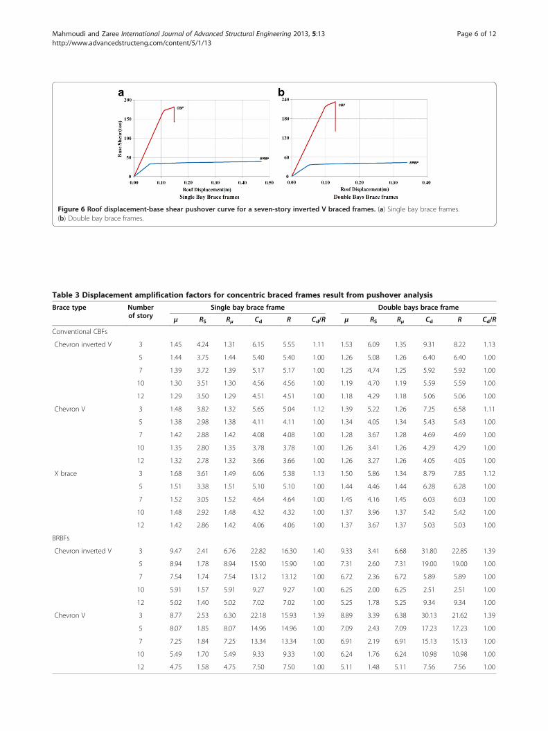
Figure 6 Roof displacement-base shear pushover curve for a seven-story inverted V braced frames. (a) Single bay brace frames.(b) Double bay brace frames.
Table 3 Displacement amplification factors for concentric braced frames result from pushover analysis
Brace type Numberof story
Single bay brace frame Double bays brace frame
μ RS Rμ Cd R Cd/R μ RS Rμ Cd R Cd/R
Conventional CBFs
Chevron inverted V 3 1.45 4.24 1.31 6.15 5.55 1.11 1.53 6.09 1.35 9.31 8.22 1.13
5 1.44 3.75 1.44 5.40 5.40 1.00 1.26 5.08 1.26 6.40 6.40 1.00
7 1.39 3.72 1.39 5.17 5.17 1.00 1.25 4.74 1.25 5.92 5.92 1.00
10 1.30 3.51 1.30 4.56 4.56 1.00 1.19 4.70 1.19 5.59 5.59 1.00
12 1.29 3.50 1.29 4.51 4.51 1.00 1.18 4.29 1.18 5.06 5.06 1.00
Chevron V 3 1.48 3.82 1.32 5.65 5.04 1.12 1.39 5.22 1.26 7.25 6.58 1.11
5 1.38 2.98 1.38 4.11 4.11 1.00 1.34 4.05 1.34 5.43 5.43 1.00
7 1.42 2.88 1.42 4.08 4.08 1.00 1.28 3.67 1.28 4.69 4.69 1.00
10 1.35 2.80 1.35 3.78 3.78 1.00 1.26 3.41 1.26 4.29 4.29 1.00
12 1.32 2.78 1.32 3.66 3.66 1.00 1.26 3.27 1.26 4.05 4.05 1.00
X brace 3 1.68 3.61 1.49 6.06 5.38 1.13 1.50 5.86 1.34 8.79 7.85 1.12
5 1.51 3.38 1.51 5.10 5.10 1.00 1.44 4.46 1.44 6.28 6.28 1.00
7 1.52 3.05 1.52 4.64 4.64 1.00 1.45 4.16 1.45 6.03 6.03 1.00
10 1.48 2.92 1.48 4.32 4.32 1.00 1.37 3.96 1.37 5.42 5.42 1.00
12 1.42 2.86 1.42 4.06 4.06 1.00 1.37 3.67 1.37 5.03 5.03 1.00
BRBFs
Chevron inverted V 3 9.47 2.41 6.76 22.82 16.30 1.40 9.33 3.41 6.68 31.80 22.85 1.39
5 8.94 1.78 8.94 15.90 15.90 1.00 7.31 2.60 7.31 19.00 19.00 1.00
7 7.54 1.74 7.54 13.12 13.12 1.00 6.72 2.36 6.72 5.89 5.89 1.00
10 5.91 1.57 5.91 9.27 9.27 1.00 6.25 2.00 6.25 2.51 2.51 1.00
12 5.02 1.40 5.02 7.02 7.02 1.00 5.25 1.78 5.25 9.34 9.34 1.00
Chevron V 3 8.77 2.53 6.30 22.18 15.93 1.39 8.89 3.39 6.38 30.13 21.62 1.39
5 8.07 1.85 8.07 14.96 14.96 1.00 7.09 2.43 7.09 17.23 17.23 1.00
7 7.25 1.84 7.25 13.34 13.34 1.00 6.91 2.19 6.91 15.13 15.13 1.00
10 5.49 1.70 5.49 9.33 9.33 1.00 6.24 1.76 6.24 10.98 10.98 1.00
12 4.75 1.58 4.75 7.50 7.50 1.00 5.11 1.48 5.11 7.56 7.56 1.00
Mahmoudi and Zaree International Journal of Advanced Structural Engineering 2013, 5:13 Page 6 of 12http://www.advancedstructeng.com/content/5/1/13

Figure 7 Nonlinear time history curves for seven-story conventional inverted V CBFs. (a) Naghan, (b) Tabas, and (c) El Centro earthquakes.
Mahmoudi and Zaree International Journal of Advanced Structural Engineering 2013, 5:13 Page 7 of 12http://www.advancedstructeng.com/content/5/1/13

Figure 8 Nonlinear time history curves for seven-story inverted V BRBFs. (a) Naghan, (b) Tabas, and (c) El Centro earthquakes.
Mahmoudi and Zaree International Journal of Advanced Structural Engineering 2013, 5:13 Page 8 of 12http://www.advancedstructeng.com/content/5/1/13

Table 4 Displacement amplification factors for concentric braced frame results from dynamic analysisBrace type Number
of storySingle bay brace frame Double bay brace frame
ΔW(mm) Δmax(mm) Cd ΔW(mm) Δmax(mm) Cd
Conventional CBFs
Chevron inverted V 3 10 48 6.03 4 31 9.27
5 20 82 5.24 14 72 6.55
7 36 134 4.84 27 127 6.03
10 77 279 4.64 60 247 5.29
12 113 370 4.21 89 330 4.75
Chevron V 3 11 47 5.45 6 35 7.32
5 25 87 4.26 19 78 5.21
7 45 139 3.87 32 123 4.86
10 86 255 3.70 73 231 3.97
12 125 346 3.46 101 314 3.86
X brace 3 8 34 6.21 6 34 8.95
5 20 75 5.54 15 67 6.60
7 37 121 4.83 28 117 6.18
10 77 230 4.39 62 216 5.17
12 125 333 3.93 90 298 4.90
BRBFs
Chevron inverted V 3 13 248 21.87 7 199 32.36
5 31 420 15.40 19 340 20.14
7 42 460 12.57 32 406 14.69
10 91 708 8.99 71 691 11.26
12 154 956 7.15 117 915 9.06
Chevron V 3 13 229 20.98 8 208 29.3
5 33 407 14.34 21 327 17.96
7 42 506 13.98 40 491 15.13
10 91 991 8.82 74 725 10.28
12 152 943 7.14 128 840 7.56
Figure 9 Displacement amplification factors for concentric braced frames. (a) CBFs and (b) BRBFs.
Mahmoudi and Zaree International Journal of Advanced Structural Engineering 2013, 5:13 Page 9 of 12http://www.advancedstructeng.com/content/5/1/13

Mahmoudi and Zaree International Journal of Advanced Structural Engineering 2013, 5:13 Page 10 of 12http://www.advancedstructeng.com/content/5/1/13
motion for CBFs was emphasized (Moghaddam andHajirasouliha 2006). To achieve overstrength factor (RS),ductility factor (μ), reduction factor due to ductility (Rμ),and finally displacement amplification factor (Cd) and itsrelation to response modification factor (R), the push-over analysis was carried out by subjecting a structure tomonotonically increasing lateral forces with an invariantheight-wise distribution.
Nonlinear time history analysisNonlinear time history analysis of a detailed analyticalmodel is perhaps the best option to estimate deform-ation demands (Hajirasouliha and Doostan 2010). Al-though pushover analysis has advantages over elasticanalysis procedures, underlying assumptions, the accur-acy of pushover predictions, and limitations of currentpushover procedures must be identified. Thus, nonlineartime history analyses have been performed to confirm
Table 5 Comparison of displacement amplification factors for
Brace type Numberof story
Single bay brace fr
Pushover analysis Time
Conventional CBFs
Chevron inverted V 3 6.15
5 5.40
7 5.17
10 4.56
12 4.51
Chevron V 3 5.65
5 4.11
7 4.08
10 3.78
12 3.66
X brace 3 6.06
5 5.10
7 4.64
10 4.32
12 4.06
BRBFs
Chevron inverted V 3 22.82
5 15.90
7 13.12
10 9.27
12 7.02
Chevron V 3 22.18
5 14.96
7 13.34
10 9.33
12 7.50
the adequacy of static (pushover) analyses. Nonlineardynamic analyses were carried out by employing suitesof time history of the El Centro, Naghan, and Tabasearthquake matching with the design spectrum. Theproperties of the records used for this study are summa-rized in Table 2.Modeling nonlinear behavior of braces, a generalized
force-deformation relation was used for steel brace elem-ent as suggested by FEMA-356 (2000) (Figure 5). Forbuckling restrained braces, the model presented in Tablesfive, six, and seven in FEMA-356 (2000) were consideredfor both tension and compression behavior (Figure 5). Thepost-yield stiffness of beams, columns, and braces was ini-tially assumed to be 2%. In Figure 5, Q, Qy, and Δ are thegeneralized component load, expected strength, and com-ponent displacement, respectively. For conventional bracein compression, the residual strength after degradation is20% of the buckling strength, and life safety plastic
concentric braced frames
ame Double bay brace frame
history analysis Pushover analysis Time history analysis
6.03 9.31 9.27
5.24 6.40 6.55
4.84 5.92 6.03
4.64 5.59 5.29
4.21 5.06 4.75
5.45 7.25 7.32
4.26 5.43 5.21
3.87 4.69 4.86
3.70 4.29 3.97
3.46 4.05 3.86
6.21 8.79 8.95
5.54 6.28 6.60
4.83 6.03 6.18
4.39 5.42 5.17
3.93 5.03 4.90
21.87 31.80 32.36
15.40 19.00 20.14
12.57 5.89 14.69
8.99 2.51 11.26
7.15 9.34 9.06
20.98 30.13 29.3
14.34 17.23 17.96
13.98 15.13 15.13
8.82 10.98 10.28
7.14 7.56 7.56

Mahmoudi and Zaree International Journal of Advanced Structural Engineering 2013, 5:13 Page 11 of 12http://www.advancedstructeng.com/content/5/1/13
deformation ΔLS is equal to 5ΔC (ΔC is the axial deform-ation at expected buckling load). On the other hand, forconventional brace in tension and buckling restrainedbrace, the life safety plastic deformation ΔLS is equal to7ΔT (ΔT is the axial deformation at expected tensile yield-ing load). Based on earlier tests, the compression strengthof BRB was assumed to be 10% larger than the strength intension (Clark 2000). In this paper, the compressionstrength for BRB is considered equal to the tensionstrength. To capture the greatest demands on braces andbeams, flexible beams were used.
Results and discussionBase shear vs. maximum roof displacement nonlinearpushover analysis for a seven-story inverted V CBF andBRBF with single and double bracing bays are shown inFigure 6. As it is shown, the stiffness of CBF is higherthan BRBF, whereas the ductility for BRBF is highercompared to CBF. Table 3 shows the displacement amp-lification factors (Cd) and its relations to response modi-fication factors (R) for both CBFs and BRBFs. Figures 7and 8 show nonlinear dynamic time history analysis re-sults of the El Centro, Naghan, and Tabas earthquakes fora seven-story inverted V CBF and BRBF with single anddouble bracing bays. Table 4 shows the displacement amp-lification factors (Cd) for both CBFs and BRBFs assessedfrom nonlinear dynamic time history analysis.The ductility in CBFs has lower values due to deterior-
ation in strength and degradation of stiffness due tobrace buckling in cyclic loading. Thus, it can be said thatthe overstrength factors have main effects on displace-ment amplification factors for CBFs. The number ofbracing bays and structure height have an effect onoverstrength and thus on Cd. On the other hand, thesefactors as such have no obvious result on ductility, sochanging the structure height and the number of bracingbay has no effect on the ratio Cd/R.In BRBFs, because of brace energy dissipation capacity
in tension and compression, the ductility has high valuesand becomes the main parameter to determine displace-ment amplification factors. Also, structure height has aprofound effect on ductility, so for BRBFs, variation in thenumber of stories has obvious impression on displacementamplification factors and the ratio Cd/R. On the otherhand, structure characteristic cause little variation inoverstrength factors and so in Cd and the ratio Cd/R.Variation in displacement amplification factors for dif-
ferent types of concentric braced frames are shown inFigure 9. The comparison of pushover and nonlineardynamic analysis displacement amplification factors areshown in Table 5. According to the results, pushoveranalysis provides good predictions of seismic demandsfor concentrically braced steel frames.
ConclusionsThis paper assesses the displacement amplification factor(Cd) and the ratio between Cd and R factor of 30 conven-tional CBFs and 20 BRBFs in life safety structural perform-ance level. For this purpose, the nonlinear static (pushover)analysis and nonlinear dynamic time history analysis havebeen performed on the buildings with single and two bra-cing bays, various stories, and different buckling restrainedbrace and conventional brace configurations. The beam-column connections were assumed to be pinned so thatthe seismic load was resisted mainly by braces. The resultsof this study can be summarized as follows:
� The displacement amplification factors increase withthe decrease of structure height and the increase inthe number of bracing bays. However, the numberof bracing bays has no effect on the ratio Cd/R inboth CBFs and BRBFs. The ratio between Cd and Rfactor is from 1 to 1.12 and 1 to 1.4 for CBFs andBRBFs, respectively.
� The displacement amplification factors for CBFs intype V, inverted V, and X are evaluated as 4.40, 5.20,and 4.90 for single bracing bay and as 5.40, 6.80, and6.60, respectively, for double bracing bays.
� The obtained displacement amplification factors fordifferent types of BRBFs with single bracing bay varyfrom 7 to 22.50, and for double bracing bays, theseare from 8 to 31.
� The structure height in CBFs has no effect on ratioCd/R, but in BRBFs, this has an effect on the ratioCd/R because of ductility variation. Thus, in ductilebrace frame systems (high ductility) and stiffbuildings (low fundamental period), the ratio Cd/R ishigher than 1 when the fundamental period (T) islower than the period of the ground motion (TC).
Competing interestsThe authors declare that they have no competing interests.
Authors' contributionsMM proposed the subject of the research and participated in the sequencealignment. He also controlled the results. ZM carried out the structuralanalysis (linear and nonlinear) and data processing and participated in thesequence alignment. All authors read and approved the final manuscript.
AcknowledgmentThis work was supported financially by the Shahid Rajaee Teacher TrainingUniversity. We would like to thank for this support.
Received: 27 November 2012 Accepted: 8 April 2013Published: 26 April 2013
ReferencesAISC (2005) Seismic provisions for structural steel buildings. American Institute of
Steel Constructions, IllinoisBHRC (2005) Iranian code of practice for seismic resistance design of buildings:
standard no.2800, 3rd edn. Building and Housing Research Center, TehranBroderick BM, Elghazouli AY, Goggins JM (2008) Earthquake testing and response
analysis of concentrically-braced sub-frames. J Constructional Steel Res 64(9):997–1007

Mahmoudi and Zaree International Journal of Advanced Structural Engineering 2013, 5:13 Page 12 of 12http://www.advancedstructeng.com/content/5/1/13
Clark P (2000) Evaluation of design methodologies for structures incorporatingsteel unbonded braces for energy dissipation. In: 12th World Conference onEarthquake Engineering Proceedings. New Zealand Society for EarthquakeEngineering, paper no. 2240. NZSEE, Wellington
Davaran A, Hoveidae N (2009) Effect of mid-connection detail on the behavior ofX-bracing systems. J Constructional Steel Res 65(4):985–990
Fajfar P (2002) Structural analysis in earthquake engineering—a breakthrough ofsimplified nonlinear methods. 12th European Conference on EarthquakeEngineering, London, 9–13 September 2002
FEMA (2000) Prestandard and commentary for the seismic rehabilitation of building,FEMA-356. Federal Emergency Management Agency, Washington, DC
Goggins JM, Broderick BM, Elghazouli AY, Lucas AS (2006) Behaviour of tubular steelmembers under cyclic axial loading. J Constructional Steel Res 62(2):121–131
Hajirasouliha I, Doostan A (2010) A simplified model for seismic responseprediction of concentrically braced frames. Adv Eng Softw 41(3):497–505
Hussain S, Benschoten PV, Satari MA, Lin S (2006) Buckling restrained bracedframe (BRBF) structures: analysis, design and approvals issues. Proceedings ofthe 75th SEAOC Annual Convention, Long Beach, 13–16 September 2006
IBC (2000) International building code. International Code Council, Washington, DCKiggins S, Uang CM (2006) Reducing residual drift of buckling-restrained braced
frames as a dual system. J Eng Struct 28(11):1525–1532Kim J, Choi H (2004) Behavior and design of structures with buckling-restrained
braces. J Eng Struct 26(6):693–706Kumar GR, Kumar SRS, Kalyanaraman V (2007) Behaviour of frames with
non-buckling bracings under earthquake loading. J Constructional Steel Res63(2):254–262
Lee SS, Goel SC, Chao SH (2004) Performance-based seismic design of steelmoment frames using target drift and yield mechanism. 13th WorldConference on Earthquake Engineering, Vancouver, B.C. Canada,1–6 August 2004. Paper No 266
Mahmoudi M (2004) The ratio of displacement amplification factor to forcereduction factor. 13th World Conference on Earthquake Engineering,Vancouver, B.C. Canada, 1–6 August 2004. Paper No. 1917
Mahmoudi M, Zaree M (2010) Evaluating response modification factors ofconcentrically braced steel frames. J Constructional Steel Res66(10):1196–1204
Mahmoudi M, Zaree M (2011) Evaluating the overstrength of concentricallybraced steel frame systems considering members post-buckling strength.J Constructional Steel Res 9(1):57–62
MHUD (2009) Iranian national building code (part 10): steel structure design.Ministry of Housing and Urban Development, Tehran
Miranda E (1993) Site-dependent strength-reduction factors. Struct Eng 119(12):3503–3519
Moghaddam H, Hajirasouliha I (2006) An investigation on the accuracy ofpushover analysis for estimating the seismic deformation of braced steelframes. J Constructional Steel Res 62(4):343–351
Nassar A, Osteraas J, Krawinkler H (1992) Seismic design based on strength andductility demands. In: Proceedings of the Earthquake Engineering TenthWorld Conference. Balkema, Rotterdam, pp 5861–5866
NEHRP (1994) Recommended provisions for the development of seismicregulations for new building. Seismic Safety Council, Washington, DC
Rai DC, Goel SC, Firmansjah G (1996) User's guide: structural nonlinear analysisprogram (SNAP-2DX). , Department of Civil and Environmental Engineering,University of Michigan, Ann Arbor
Riddell R, Hidalgo P, Cruz E (1989) Response modification factors for earthquakeresistant design of short period buildings. Earthquake Spectra 5(3):571–589
Sahoo DR, Chao SH (2010) Performance-based plastic design method forbuckling restrained braced frames. J Eng Struct 32(9):2950–2958
Schmidt BJ, Bartlett FM (2002) Review of resistance factor for steel: resistancedistributions and resistance factor calibration. Can J Civ Eng 29:109–118
Uang CM (1991) Establishing R (or Rw) and Cd factor for building seismicprovision. J Struct Eng 117(1):19–28
Uang CM, Maarouf A (1994) Deflection amplification factor for seismic designprovisions. J Struct Eng 120(8):2423–243
doi:10.1186/2008-6695-5-13Cite this article as: Mahmoudi and Zaree: Evaluating the displacementamplification factors of concentrically braced steel frames. InternationalJournal of Advanced Structural Engineering 2013 5:13.
Submit your manuscript to a journal and benefi t from:
7 Convenient online submission
7 Rigorous peer review
7 Immediate publication on acceptance
7 Open access: articles freely available online
7 High visibility within the fi eld
7 Retaining the copyright to your article
Submit your next manuscript at 7 springeropen.com