original minimess test points
TRANSCRIPT

Test point Screw cap thread Nominal diameter
Max. operating pressure¹
Material selection Seal materials
MINIMESS® 1620 M16x2 DN2 630 bar
1.0718 free cutting steel
1.4571 stainless steel
NBR (Perbunan)
FKM (Viton)
MINIMESS® 1620 p/T M16x2 DN2 630 bar
MINIMESS® 1615 M16x1,5 DN2 630 bar
MINIMESS® 1215 Buttress thread 12 DN2 630 bar
MINIMESS® 1604 Buttress thread 16 DN4 400 bar
MINIMESS®
Original MINIMESS® test pointsThe benchmark for test couplings
MINIMESS® test points serve as system access points for analyses and tests in fluid circuits, and can be used to make a leak-tight connection under pressure. This makes it possible to connect sensors or pressure gauges or draw samples as necessary without any downtimes. Moreover, the test points can be used to fill, vent, and empty systems.
Original MINIMESS® test points I Are an integral part of measuring and testing equipment
I Can be used to make leak-tight connections under pressure
I Open and close automatically when a hose or sensor is connected / disconnected
I Save time and money by making diagnostics and maintenance faster, improving machine availability as
a result
I Save money by ensuring that expensive sensors do not have to be permanently installed for servicing
purposes
I Conform to ISO 15171-2 (MINIMESS® 1620)
I Have a four-fold safety factor in regard to bursting
I Are certified with 1,000,000 pressure pulses at 1.3 times the operating pressure
I Can also be used at low temperatures
I Are highly resistant to corrosion (salt spray test longer than 1,000 hours)
I Are suitable, without restrictions, for HL, HLP, HVLP hydraulic fluids in conformity with DIN 51524
The original MINIMESS® 1620 p/T test point is a multipurpose test point that can be used to simultaneously
measure pressure and temperature at a single measuring point. As a result, the number of required measuring
points can be reduced by up to 50%.
The temperature is measured directly in the flowing fluid, resulting in extremely short response times.
For information on compatible HySense® p/T combo sensors, please refer to page 144.
Additional materials and seal materials available upon request.
¹ Depends on the size of the stud end.
10 | 11

Thread Seal type1 Technical specifications Material: 1.0718free cutting steel
Material: 1.4571Stainless steel
G M²Nm
pn³bar
Hmm
imm
AFmm
Part No.with metal cap &
NBR seals
Part No.with metal cap &
FKM seals
Metric ISO thread
M10 x 1 E 20 630 37.5 9.5 17 2103-01-94.00N –
M10 x 1 F 20 400 37.6 8 17 2103-01-12.00N 2703-01-12.10
M10 x 1 G 15 630 37.5 8.5 17 2103-01-33.00N 2703-01-33.10
M12 x 1.5 B 45 630 36 10 17 2103-01-48.00N –
M12 x 1.5 E 35 630 35.1 11 17 2103-01-95.00N –
M12 x 1.5 F 45 630 36 10 17 2103-01-13.00N 2703-01-13.10
M14 x 1.5 B 60 630 36 10 19 2103-01-49.00N –
M14 x 1.5 E 45 630 35.5 11 19 2103-01-96.00N –
M14 x 1.5 F 60 630 36 10 19 2103-01-14.00N 2703-01-14.10
M16 x 1.5 F 80 630 36 10 22 2103-01-15.00N –
Whitworth thread
ISO 228-G 1/8 F 20 400 38 8 17 2103-01-17.00N 2703-01-17.10
ISO 228-G 1/4 B 60 630 36 10 19 2103-01-51.00N 2703-01-51.10
ISO 228-G 1/4 F 60 630 36 10 19 2103-01-18.00N 2703-01-18.10
ISO 228-G 3/8 F 90 630 36 10 22 2103-01-16.00N 2703-01-16.10
UNF thread
7/16-20 UNF E 20 630 37 11 17 2103-01-B5.00N 2703-01-B5.10
9/16-18 UNF E 35 630 36 12 17 2103-01-B6.00N 2703-01-B6.10
Tapered thread
ISO 7/I-R 1/8 C – 400 33 13 17 2103-01-40.00N –
ISO 7/I-R 1/4 C – 630 33 13 17 2103-01-41.00N 2703-01-41.10
NPTF thread
1/8 NPTF H – 400 33 9.5 17 2103-01-46.00N –
1/4 NPTF H – 630 33 16.5 17 2103-01-47.00N 2703-01-47.10
Options
Part No. with FKM seals XXXX-XX-XX.10N –
Part No. with plastic cap XXXX-30-XX.XXN XXXX-30-XX.XX
Operating temperature ranges:With NBR seals: -25 °C … 100 °C / With FKM seals: -20 °C … 200 °C / With plastic cap: Max. 100 °C
Additional versions, materials, and seal materials available upon request.
- HYDROTECHNIK GmbH Holzheimer Str. 94-96 D-65549 Limburg Tel.: +49 6431 4004-0 www.hydrotechnik.com
- - - Zeichnungsnummer/drawing no.
Z 1620_Minimess_Kupplung_Kunststoffkappe Datum/date Revision Dokumentenart/
document type Dokumentenstatus/ document state
Name Freigabe-Nr./ release-no.
Blatt/sheet
- 0 Kundenzeichnung In Bearbeitung - - 1/1
H +
3 m
m 19
- HYDROTECHNIK GmbH Holzheimer Str. 94-96 D-65549 Limburg Tel.: +49 6431 4004-0 www.hydrotechnik.com
- - - Zeichnungsnummer/drawing no.
Z 1620_Minimess_Kupplung Datum/date Revision Dokumentenart/
document type Dokumentenstatus/ document state
Name Freigabe-Nr./ release-no.
Blatt/sheet
- 0 Kundenzeichnung In Bearbeitung - - 1/1
20
Hi
G
SWAF
Type B Type C Type E Type F Type G Type H
- HYDROTECHNIK GmbH Holzheimer Str. 94-96 D-65549 Limburg Tel.: +49 6431 4004-0 www.hydrotechnik.com
- - - Zeichnungsnummer/drawing no.
Z 1620_Minimess_Kupplung_Kunststoffkappe Datum/date Revision Dokumentenart/
document type Dokumentenstatus/ document state
Name Freigabe-Nr./ release-no.
Blatt/sheet
- 0 Kundenzeichnung In Bearbeitung - - 1/1
H +
3 m
m 19
- HYDROTECHNIK GmbH Holzheimer Str. 94-96 D-65549 Limburg Tel.: +49 6431 4004-0 www.hydrotechnik.com
- - - Zeichnungsnummer/drawing no.
Z 1620_Minimess_Kupplung Datum/date Revision Dokumentenart/
document type Dokumentenstatus/ document state
Name Freigabe-Nr./ release-no.
Blatt/sheet
- 0 Kundenzeichnung In Bearbeitung - - 1/1
20
Hi
G
SWAF
Type B Type C Type E Type F Type G Type H
MINIMESSMINIMESS®
Type B Type C Type E Type F Type G Type H
Original MINIMESS® 1620 test point
The MINIMESS® 1620 test point with an M16 x 2 thread is the top seller among test couplings and is used for
most standard applications. It can be used with operating pressures of up to 630 bar and is available in a wide
variety of versions with various international threads and seal types.
Version with metal cap
Seal types
Version with plastic cap
¹ For detailed specifications regarding the seal types, please refer to pages 62 – 64
² M = Tightening torque for stud end in conformity with the applicable standards. It is the user’s own responsibility to determine the appropriate installation torque for their specific installation situation.
³ pn = Maximum operating pressure
12 | 13

Thread Seal type1 Technical specifications Material: 1.0718free cutting steel
Material: 1.4571Stainless steel
G M²Nm
pn³bar
Hmm
imm
AFmm
Part No.with metal cap &
NBR seals
Part No.with metal cap &
FKM seals
Metric ISO thread
M10 x 1 G 15 630 37.5 8.5 17 2102-01-33.00N 2702-01-33.10
M12 x 1.5 F 45 630 36 10 17 2102-01-13.00N 2702-01-13.10
M14 x 1.5 B 60 630 36 10 19 2102-01-49.00N –
M14 x 1.5 F 60 630 36 10 19 2102-01-14.00N 2702-01-14.10
Whitworth thread
ISO 228-G 1/8 F 20 400 38 8 17 2102-01-17.00N –
ISO 228-G 1/4 B 60 630 36 10 19 2102-01-51.00N –
ISO 228-G 1/4 F 60 630 36 10 19 2102-01-18.00N 2702-01-18.10
Options
Part No. with FKM seals XXXX-XX-XX.10N –
Operating temperature ranges: With NBR seals: -25 °C … 100 °C / With FKM seals: -20 °C … 200 °C
Additional versions, materials, and seal materials available upon request.
Thread Seal type1 Technical specifications Material: 1.0718free cutting steel
Material: 1.4571Stainless steel
G M²Nm
pn³bar
Hmm
imm
Lmm
AFmm
Part No.with metal cap &
NBR seals
Part No.with metal cap &
FKM seals
Metric ISO thread
M10 x 1 G 15 630 38 8.5 16 17 2149-04-19.13N 2749-04-19.53
Whitworth thread
ISO 228-G 1/4 F 60 630 36.5 10 16 19 2149-04-15.13N 2749-04-15.53
Options
Part No. with FKM seals XXXX-XX-XX.53N –
Part No. with EPDM seals XXXX-XX-XX.43N –
Operating temperature ranges:With NBR seals: -25 °C … 100 °C / With FKM seals: -20 °C … 200 °C / With EPDM seal: -40 °C … 125 °C
Additional versions, materials, and seal materials available upon request.
MINIMESS®
- HYDROTECHNIK GmbH Holzheimer Str. 94-96 D-65549 Limburg Tel.: +49 6431 4004-0 www.hydrotechnik.com
- - - Zeichnungsnummer/drawing no.
Z 1615_Minimess_Kupplung Datum/date Revision Dokumentenart/
document type Dokumentenstatus/ document state
Name Freigabe-Nr./ release-no.
Blatt/sheet
- 0 Kundenzeichnung In Bearbeitung - - 1/1
Hi
G
20
SWAF
Type B Type C Type E Type F Type G Type HType B Type C Type E Type F Type G Type HType B Type C Type E Type F Type G Type HType B Type C Type E Type F Type G Type H
Seal types
HYDROTECHNIK GmbH Holzheimer Str. 94-96 D-65549 Limburg Tel.: +49 6431 4004-0 www.hydrotechnik.com
- - - Zeichnungsnummer/drawing no.
Z 1620_p_t_kupplung Datum/date Revision Dokumentenart/
document type Dokumentenstatus/ document state
Name Freigabe-Nr./ release-no.
Blatt/sheet
- 0 Kundenzeichnung In Bearbeitung - - 1/1
Li
H
G
20
SWAF
Type B Type C Type E Type F Type G Type HType B Type C Type E Type F Type G Type H
Seal types
1 For detailed specifications regarding the seal types, please refer to pages 62 – 64
² M = Tightening torque for stud end in conformity with the applicable standards. It is the user’s own responsibility to determine the appropriate installation torque for their specific installation situation.
³ pn = Maximum operating pressure
Original MINIMESS® 1620 p/T test point Original MINIMESS® 1615 test point
The MINIMESS® 1620 p/T test point can be used to simultaneously
measure pressure and temperature with only one single test
coupling by using a p/T multipurpose sensor. This results in fewer
measuring points and sensors being required.
The p/T test point can be used with operating pressures of up to
630 bar.
The MINIMESS® 1615 test point was developed primarily
for military applications and has an alternative M16 x 1.5
coupling thread available. It can be used with operating
pressures of up to 630 bar and is available with various
threads.
¹ For detailed specifications regarding the seal types, please refer to pages 62 – 64
² M = Tightening torque for stud end in conformity with the applicable standards. It is the user’s own responsibility to determine the appropriate installation torque for their specific installation situation.
³ pn = Maximum operating pressure
14 | 15

Thread Seal type1 Technical specifications Material: 1.0718free cutting steel
Material: 1.4571Stainless steel
G M²Nm
pn³bar
Hmm
imm
AFmm
Part No.with metal cap &
NBR seals
Part No.with metal cap &
FKM seals
Metric ISO thread
M10 x 1 G 15 630 30 8.5 14 2101-06-33.00N 2701-06-33.10
M12 x 1.5 E 35 630 29 11 17 2101-06-76.00N –
M12 x 1.5 F 45 630 29 10 17 2101-06-13.00N –
M14 x 1.5 E 45 630 29 11 19 2101-06-96.00N –
M14 x 1.5 F 60 630 29 10 19 2101-06-14.00N –
Whitworth thread
ISO 228-G 1/8 F 20 400 30 8 14 2101-06-17.00N 2701-06-17.10
ISO 228-G 1/4 F 60 630 29 10 19 2101-06-18.00N 2701-06-18.10
UNF thread
7/16-20 UNF E 20 630 29 11 17 2103-06-B5.00N 2701-06-B5.10
9/16-18 UNF E 35 630 28 12 17 2103-06-B6.00N –
Tapered thread
1/8 NPTF H – 400 26 12 14 2101-06-46.00N 2701-06-46.10
1/4 NPTF H – 630 26 15 14 2101-06-47.00N 2701-06-47.10
Options
Part No. with FKM seals XXXX-XX-XX.10N –
Part No. with plastic cap XXXX-01-XX.XXN XXXX-01-XX.XX
Operating temperature ranges:With NBR seals: -25 °C … 100 °C / With FKM seals: -20 °C … 200 °C / With plastic cap: Max. 100 °C
Additional versions, materials, and seal materials available upon request.
Version with metal cap Version with plastic cap
MINIMESS®
- HYDROTECHNIK GmbH Holzheimer Str. 94-96 D-65549 Limburg Tel.: +49 6431 4004-0 www.hydrotechnik.com
- - - Zeichnungsnummer/drawing no.
Z 1215_Minimess_Kupplung_Kunststoffkappe Datum/date Revision Dokumentenart/
document type Dokumentenstatus/ document state
Name Freigabe-Nr./ release-no.
Blatt/sheet
- 0 Kundenzeichnung In Bearbeitung - - 1/1
H +
3 m
m
20
- HYDROTECHNIK GmbH Holzheimer Str. 94-96 D-65549 Limburg Tel.: +49 6431 4004-0 www.hydrotechnik.com
- - - Zeichnungsnummer/drawing no.
Z 1215_Minimess_Kupplung Datum/date Revision Dokumentenart/
document type Dokumentenstatus/ document state
Name Freigabe-Nr./ release-no.
Blatt/sheet
- 0 Kundenzeichnung In Bearbeitung - - 1/1
Hi
17
G
SWAF
Type B Type C Type E Type F Type G Type HType B Type C Type E Type F Type G Type H
Seal types¹ For detailed specifications regarding the seal types, please refer to pages 62 – 64
² M = Tightening torque for stud end in conformity with the applicable standards. It is the user’s own responsibility to determine the appropriate installation torque for their specific installation situation.
³ pn = Maximum operating pressure
Original MINIMESS® 1215 test point
The MINIMESS® 1215 test point is characterized by a small coupling thread, resulting in a very compact design. It was
originally developed as an alternative test point for metrological applications in places where space is tight. The test point
can be used with operating pressures of up to 630 bar and is available with various international threads and seal types.
16 | 17

Thread Seal type1 Technical specifications Material: 1.0718free cutting steel
Material: 1.4571Stainless steel
G M²Nm
pn³bar
Hmm
imm
AFmm
Part No.with metal cap &
NBR seals
Part No.with metal cap &
FKM seals
Metric ISO thread
M10 x 1 G 15 400 43 8.5 17 2106-01-33.00N –
M12 x 1.5 F 45 400 40 10 17 2106-01-13.00N –
M14 x 1.5 F 60 400 40 10 19 2106-01-14.00N –
Whitworth thread
ISO 228-G 1/4 F 60 400 40 10 19 2106-01-18.00N 2706-01-18.10
Options
Part No. with FKM seals XXXX-XX-XX.10N –
Operating temperature ranges:With NBR seals: -25 °C … 100 °C / With FKM seals: -20 °C … 200 °C
Additional versions, materials, and seal materials available upon request.
MINIMESS®
- HYDROTECHNIK GmbH Holzheimer Str. 94-96 D-65549 Limburg Tel.: +49 6431 4004-0 www.hydrotechnik.com
- - - Zeichnungsnummer/drawing no.
Z 1604_Minimess_Kupplung Datum/date Revision Dokumentenart/
document type Dokumentenstatus/ document state
Name Freigabe-Nr./ release-no.
Blatt/sheet
- 0 Kundenzeichnung In Bearbeitung - - 1/1
H
G
22
i
SWAF
Type B Type C Type E Type F Type G Type HType B Type C Type E Type F Type G Type H
¹ For detailed specifications regarding the seal types, please refer to pages 62 – 64
² M = Tightening torque for stud end in conformity with the applicable standards. It is the user’s own responsibility to determine the appropriate installation torque for their specific installation situation.
³ pn = Maximum operating pressure
Original MINIMESS® 1604 test point
The MINIMESS® 1604 test point is particularly suitable for
quickly filling or emptying systems as a result of its nominal
diameter of DN4.
The test point can be used with operating pressures of up to
400 bar and is available with various threads.
Seal types
18 | 19
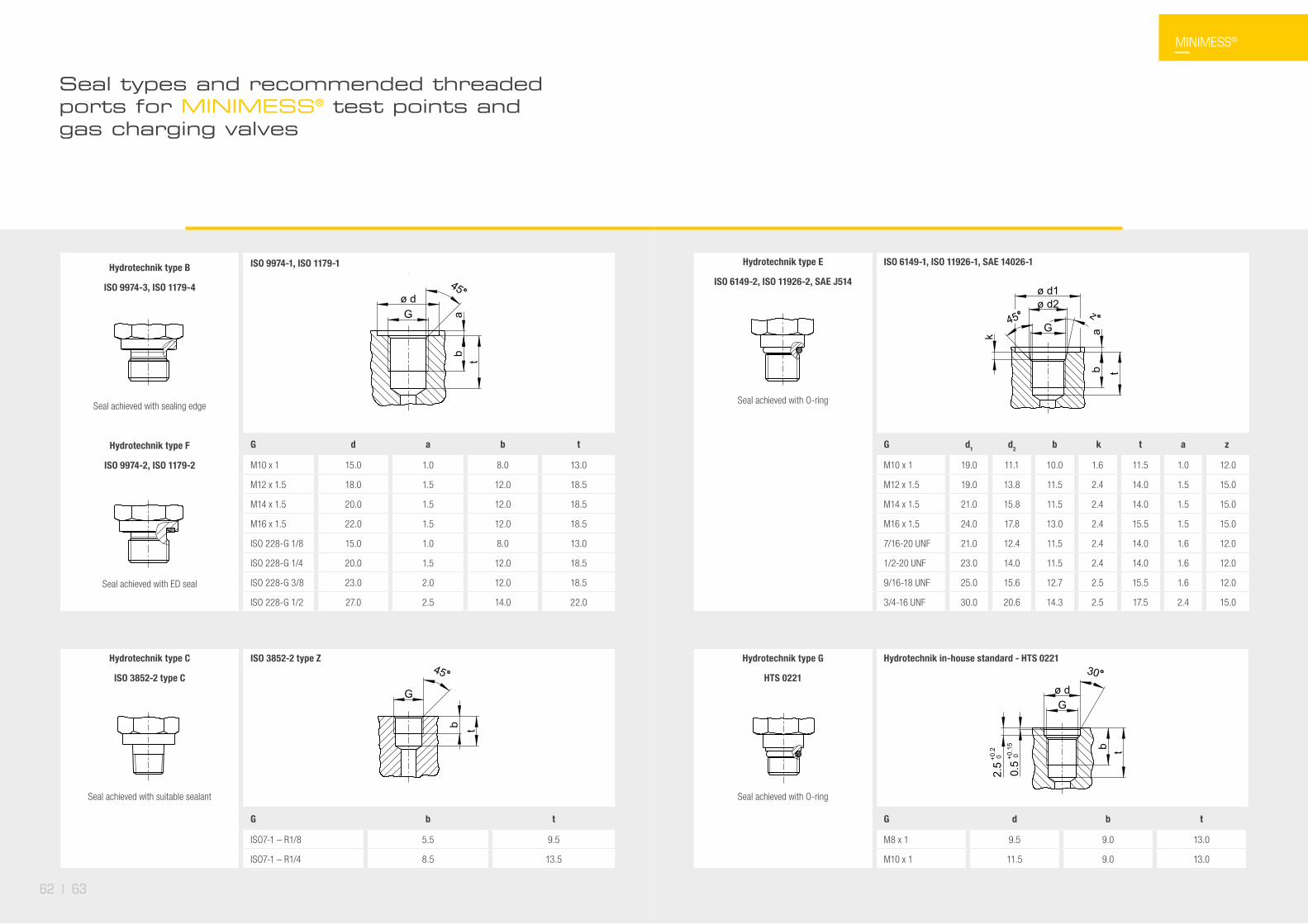
Hydrotechnik type B
ISO 9974-3, ISO 1179-4
Seal achieved with sealing edge
Hydrotechnik type F
ISO 9974-2, ISO 1179-2
Seal achieved with ED seal
ISO 9974-1, ISO 1179-1
G d a b t
M10 x 1 15.0 1.0 8.0 13.0
M12 x 1.5 18.0 1.5 12.0 18.5
M14 x 1.5 20.0 1.5 12.0 18.5
M16 x 1.5 22.0 1.5 12.0 18.5
ISO 228-G 1/8 15.0 1.0 8.0 13.0
ISO 228-G 1/4 20.0 1.5 12.0 18.5
ISO 228-G 3/8 23.0 2.0 12.0 18.5
ISO 228-G 1/2 27.0 2.5 14.0 22.0 - HYDROTECHNIK GmbH
Holzheimer Str. 94-96 D-65549 Limburg Tel.: +49 6431 4004-0 www.hydrotechnik.com
- - - Zeichnungsnummer/drawing no.
Z Einschraubzapfen Form B Datum/date Revision Dokumentenart/
document type Dokumentenstatus/ document state
Name Freigabe-Nr./ release-no.
Blatt/sheet
- 0 Kundenzeichnung In Bearbeitung - - 1/1
ø dG a
b t
45
- HYDROTECHNIK GmbH Holzheimer Str. 94-96 D-65549 Limburg Tel.: +49 6431 4004-0 www.hydrotechnik.com
- - - Zeichnungsnummer/drawing no.
Z Einschraubzapfen Form F Datum/date Revision Dokumentenart/
document type Dokumentenstatus/ document state
Name Freigabe-Nr./ release-no.
Blatt/sheet
- 0 Kundenzeichnung In Bearbeitung - - 1/1
45ø dG a
b t
- HYDROTECHNIK GmbH Holzheimer Str. 94-96 D-65549 Limburg Tel.: +49 6431 4004-0 www.hydrotechnik.com
- - - Zeichnungsnummer/drawing no.
Z Einschraubzapfen Form B Datum/date Revision Dokumentenart/
document type Dokumentenstatus/ document state
Name Freigabe-Nr./ release-no.
Blatt/sheet
- 0 Kundenzeichnung In Bearbeitung - - 1/1
ø dG a
b t
45
Hydrotechnik type C
ISO 3852-2 type C
Seal achieved with suitable sealant
ISO 3852-2 type Z
G b t
ISO7-1 – R1/8 5.5 9.5
ISO7-1 – R1/4 8.5 13.5
- HYDROTECHNIK GmbH Holzheimer Str. 94-96 D-65549 Limburg Tel.: +49 6431 4004-0 www.hydrotechnik.com
- - - Zeichnungsnummer/drawing no.
Z Einschraubzapfen_Form_C Datum/date Revision Dokumentenart/
document type Dokumentenstatus/ document state
Name Freigabe-Nr./ release-no.
Blatt/sheet
- 0 Kundenzeichnung In Bearbeitung - - 1/1
b t
G
45
Hydrotechnik type E
ISO 6149-2, ISO 11926-2, SAE J514
Seal achieved with O-ring
ISO 6149-1, ISO 11926-1, SAE 14026-1
G d1 d2 b k t a z
M10 x 1 19.0 11.1 10.0 1.6 11.5 1.0 12.0
M12 x 1.5 19.0 13.8 11.5 2.4 14.0 1.5 15.0
M14 x 1.5 21.0 15.8 11.5 2.4 14.0 1.5 15.0
M16 x 1.5 24.0 17.8 13.0 2.4 15.5 1.5 15.0
7/16-20 UNF 21.0 12.4 11.5 2.4 14.0 1.6 12.0
1/2-20 UNF 23.0 14.0 11.5 2.4 14.0 1.6 12.0
9/16-18 UNF 25.0 15.6 12.7 2.5 15.5 1.6 12.0
3/4-16 UNF 30.0 20.6 14.3 2.5 17.5 2.4 15.0
- HYDROTECHNIK GmbH Holzheimer Str. 94-96 D-65549 Limburg Tel.: +49 6431 4004-0 www.hydrotechnik.com
- - - Zeichnungsnummer/drawing no.
Z Einschraubzapfen Form E Datum/date Revision Dokumentenart/
document type Dokumentenstatus/ document state
Name Freigabe-Nr./ release-no.
Blatt/sheet
- 0 Kundenzeichnung In Bearbeitung - - 1/1
ø d1ø d2
Gz45
ab t
k
Hydrotechnik type G
HTS 0221
Seal achieved with O-ring
Hydrotechnik in-house standard - HTS 0221
G d b t
M8 x 1 9.5 9.0 13.0
M10 x 1 11.5 9.0 13.0
- HYDROTECHNIK GmbH Holzheimer Str. 94-96 D-65549 Limburg Tel.: +49 6431 4004-0 www.hydrotechnik.com
- - - Zeichnungsnummer/drawing no.
Z Einschraubzapfen_Form_G Datum/date Revision Dokumentenart/
document type Dokumentenstatus/ document state
Name Freigabe-Nr./ release-no.
Blatt/sheet
- 0 Kundenzeichnung In Bearbeitung - - 1/1
30
Gø d
0.5 +
0.15
0
2.5 +
0.2
0
b t
MINIMESS®
Seal types and recommended threaded ports for MINIMESS® test points and gas charging valves
62 | 63

Hydrotechnik type H
ANSI/ASME B1.20.2 type H
Self-sealing thread
ANSI / ASME B1.20.2 type H
G t
1/8 NPTF 12.0
1/4 NPTF 17.5
G
- HYDROTECHNIK GmbH Holzheimer Str. 94-96 D-65549 Limburg Tel.: +49 6431 4004-0 www.hydrotechnik.com
- - - Zeichnungsnummer/drawing no.
Z Einschraubzapfen Form H Datum/date Revision Dokumentenart/
document type Dokumentenstatus/ document state
Name Freigabe-Nr./ release-no.
Blatt/sheet
- 0 Kundenzeichnung In Bearbeitung - - 1/1
45
t
Hydrotechnik type F
*) Recommended minimum drilled depth
Hydrotechnik type G
*) Recommended minimum drilled depth
1.5
20
HYDROTECHNIK GmbH Holzheimer Str. 94-96 D-65549 Limburg Tel.: +49 6431 4004-0 www.hydrotechnik.com
- - Zeichnungsnummer/drawing no.
Z Einschraubbohrung für p/T Form F Datum/date Revision Dokumentenart/
document type Dokumentenstatus/ document state
Name Freigabe-Nr./ release-no.
Blatt/sheet
- 0 Kundenzeichnung In Bearbeitung - - 1/1
12
G1/4
45
27 *
)
- HYDROTECHNIK GmbH Holzheimer Str. 94-96 D-65549 Limburg Tel.: +49 6431 4004-0 www.hydrotechnik.com
- - - Zeichnungsnummer/drawing no.
Z Einschraubbohrung für p/T Form G Datum/date Revision Dokumentenart/
document type Dokumentenstatus/ document state
Name Freigabe-Nr./ release-no.
Blatt/sheet
- 0 Kundenzeichnung In Bearbeitung - - 1/1
30
0.5 +
0.15
0
11.5
2.5 +
0.2
0
M10x1
925
.5 *
)
Druckverlustkurven Minimess® Schläuche und Schlauchleitungen
In beiden Diagrammen zeigt Graph 1 den Druckverlust des Schlauchs ohne Armaturen. Graph 2 zeigt den Druckverlust der Schlauchleitung mit beidseitig angeschlossenen MINIMESS® Armaturen. Die Öl-Viskosität beträgt jeweils 30 mm2s-1.
0.0
0.5
1.0
1.5
2.0
2.5
3.0
3.5
4.0
4.5
0.2 0.4 0.6 1 1.2 1.4
Pres
sure
loss
Δp
[MPa
/m]
0.8Flow rate Q [L/min]
Pressure loss curve for DN2 hose and hose line
Pressure loss curve for DN2 hose Pressure loss curve for DN2 hose line
0.0
0.5
1.0
1.5
2.0
2.5
3.0
3.5
4.0
4.5
1 2 3 6 7 84 5
Flow rate Q [L/min]
Pressure loss curve for DN4 hose and hose line
Pressure loss curve for DN4 hose Pressure loss curve for DN4 hose line
Pres
sure
loss
Δp
[MPa
/m]
MINIMESS®
Seal types and recommended threaded ports for MINIMESS® test points and gas charging valves
Pressure loss curves for MINIMESS® hoses and hose lines
In both diagrams, curve 1 shows the pressure loss of the hose without fittings. Meanwhile, curve 2 shows the pressure loss of the hose line with MINIMESS® fittings on both ends.
The oil viscosity is 30 mm²·s¯¹ in both.
Recommended threaded ports for MINIMESS® p/T test points
64 | 65