origami lithium-ion batteries - arizona state university(shown in supplementary fig. 1c) was folded...
TRANSCRIPT

ARTICLE
Received 25 Sep 2013 | Accepted 17 Dec 2013 | Published 28 Jan 2014
Origami lithium-ion batteriesZeming Song1, Teng Ma1, Rui Tang2, Qian Cheng1, Xu Wang1, Deepakshyam Krishnaraju1, Rahul Panat1,
Candace K. Chan1, Hongyu Yu2 & Hanqing Jiang1
There are significant challenges in developing deformable devices at the system level that
contain integrated, deformable energy storage devices. Here we demonstrate an origami
lithium-ion battery that can be deformed at an unprecedented high level, including folding,
bending and twisting. Deformability at the system level is enabled using rigid origami, which
prescribes a crease pattern such that the materials making the origami pattern do not
experience large strain. The origami battery is fabricated through slurry coating of electrodes
onto paper current collectors and packaging in standard materials, followed by folding using
the Miura pattern. The resulting origami battery achieves significant linear and areal
deformability, large twistability and bendability. The strategy described here represents the
fusion of the art of origami, materials science and functional energy storage devices, and
could provide a paradigm shift for architecture and design of flexible and curvilinear elec-
tronics with exceptional mechanical characteristics and functionalities.
DOI: 10.1038/ncomms4140
1 School for Engineering of Matter, Transport and Energy, Arizona State University, Tempe, Arizona 85287, USA. 2 School of Earth and Space Exploration,School of Electrical, Computer and Energy Engineering, Arizona State University, Tempe, Arizona 85287, USA. Correspondence and requests for materialsshould be addressed to H.J. (email: [email protected]).
NATURE COMMUNICATIONS | 5:3140 | DOI: 10.1038/ncomms4140 | www.nature.com/naturecommunications 1
& 2014 Macmillan Publishers Limited. All rights reserved.
Deformable energy storage devices are emerging asindispensable components for unconventional electronicdevices that are able to survive significant degrees of
deformation, mainly bending and stretching, with strain levelsmuch greater than 1%. Examples include flexible displays1–4,stretchable circuits5, hemispherical electronic eyes6 and therecently developed epidermal electronics7. The energy storagedevices present a significant challenge for developing a robustdeformable system since they must be seamlessly integrated withdeformable functional devices and energy supplies with similarmechanical characteristics, including linear deformability (that is,stretchability and compressibility), bendability and twistability.For bending deformation, many thin-film-based energy solutionssuch as supercapacitors8–11 and batteries10,12–16 have beendeveloped that take advantage of the inherently small strains(usually less than 1%) near the mechanical neutral planes17.Recently, a handful of efforts have been undertaken to developstretchable energy sources. Stretchable supercapacitors usingbuckled carbon nanotube (CNT) macrofilms as electrodes18,19
and CNT-coated porous conductive textiles20 have beendeveloped with over 30% stretchability. Stretchable lithium-ionbatteries (LIBs) with over 100% stretchability and 50% arealcoverage have been demonstrated that used serpentineinterconnects and that were packaged by elastomericmaterials21. To date, approaches that simultaneously achieve ahigh level of deformability (including linear stretching andcompression, bending, twisting and their combinations in anyorder) with large areal coverage that are compatible withcommercially available manufacturing technologies have notbeen demonstrated. These attributes represent desiredrequirements to fully integrate energy storage devices withdeformable electronics to reach system-level deformability inrealistic applications.
Origami-based approaches represent a potentially game-changing alternative to enable deformability over existingmethods that use elastomeric materials and mechanicallydesigned structures such as buckling and serpentine shapes.Using origami, the ancient art of paper folding, compactdeformable three-dimensional structures can be created fromtwo-dimensional sheets through high degrees of folding alongpredefined creases. Origami-based approaches have recently beenpursued in several practical applications, including a foldabletelescope lens22 for space exploration and in heart stents23.
In this paper, we report an approach to enable origami LIBswith the attributes of extreme mechanical deformability, includ-ing significant system-level linear and areal deformability, largetwistability and bendability, and up to 74% areal coverage.Furthermore, commercially standard packaging technologies areused in the origami LIBs, which when combined with otherdeformable electronic devices may lead to direct practicalapplications.
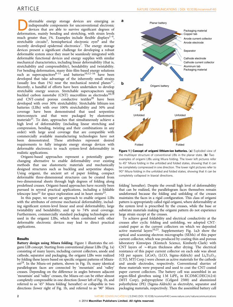
ResultsBattery design using Miura folding. Figure 1 illustrates the ori-gami LIB concept. Starting from conventional planar LIBs (Fig. 1a)consisting of many layers, including current collectors, anode andcathode, separator and packaging, the origami LIBs were realizedby folding these layers based on specific origami patterns of Miura-ori24. In the Miura-ori pattern, shown in Fig. 1b, many identicalparallelogram faces are connected by ‘mountain’ and ‘valley’creases. Depending on the difference in angles between adjacent‘mountain’ and ‘valley’ creases, the Miura-ori can be either almostcompletely compressible in one direction (lower left of Fig. 1b, andreferred to as ‘45� Miura folding’ hereafter) or collapsible in twodirections (lower right of Fig. 1b, and referred to as ‘90� Miura
folding’ hereafter). Despite the overall high level of deformabilitythat can be realized, the parallelogram faces themselves remainundeformed because the folding and unfolding of the creasesmaintains the faces in a rigid configuration. This class of origamipattern is appropriately called rigid origami, where deformability atthe system level is prescribed by the creases, while the base orsubstrate materials making the origami pattern do not experiencelarge strain except at the creases.
To achieve good foldability and electrical conductivity at thecreases after cyclic folding and unfolding, we adopted CNT-coated paper as the current collectors on which we depositedactive material layers10,25. Supplementary Fig. 1a,b show theoptical and scanning electron micrographs (SEMs) of this papercurrent collector, which was produced by coating thin and porouslaboratory Kimwipes (Kimtech Science, Kimberly-Clark) withCNT layers of B40 mm thickness after drying. The electricalresistance of this paper current collector on each side was about5O per square. LiCoO2 (LCO, Sigma-Aldrich) and Li4Ti5O12
(LTO, MTI Corp.) were chosen as active materials for the cathodeand anode electrodes, respectively. Conventional slurries ofthese materials were prepared and used to coat the CNT-coatedpaper current collectors. The battery cell was assembled in anargon-filled glovebox using 1 M LiPF6 in EC:DMC:DEC(4:2:4)(MTI Corp), polypropylene (Celgard 2500) and aluminizedpolyethylene (PE) (Sigma-Aldrich) as electrolyte, separator andpackaging materials, respectively. Then the assembled battery cell
Packaging materialCopper tab
Anode current collectorAnode electrode
Separator
Cathode electrodeCathode current collectorAluminum tabPackaging material
~90°45°
FoldedFolded
Unfolded Unfolded
Planar battery
Origami battery
Figure 1 | Concept of origami lithium-ion batteries. (a) Exploded view of
the multilayer structure of conventional LIBs in the planar state. (b) Two
examples of origami LIBs using Miura folding. The lower left pictures refer
to 45� Miura folding in the unfolded and folded states, showing that it can
be completely compressed in one direction. The lower right pictures refer to
90� Miura folding in the unfolded and folded states, showing that it can be
completely collapsed in biaxial directions.
ARTICLE NATURE COMMUNICATIONS | DOI: 10.1038/ncomms4140
2 NATURE COMMUNICATIONS | 5:3140 | DOI: 10.1038/ncomms4140 | www.nature.com/naturecommunications
& 2014 Macmillan Publishers Limited. All rights reserved.

(shown in Supplementary Fig. 1c) was folded using the desiredorigami patterns (Fig. 1) in an ambient environment. Thethickness of the assembled LIB cell was 380 mm. SupplementaryFig. 1d–g provides optical and SEM images of as-coated anodeand cathode electrodes in the regions of a crease, showing thatthere were no apparent cracks or delamination of active materialsfrom the electrodes, as compared with the planar regions.Moreover, it was verified that the electrical resistance of theelectrodes before and after folding in the origami pattern (withoutpackaging) remained unchanged. Galvanostatic charge anddischarge tests were performed using a battery testing unit(Arbin Instruments). Details appear in the Methods section.
Electrochemical and mechanical characteristics. Figure 2 showsthe results for the LIBs using 45� Miura folding. Figure 2a,bshows the pictures of the planar and completely compressedconfigurations, respectively. The dotted black lines highlight thearea of anode and cathode electrodes, which provides over 74%areal coverage. Electrochemical properties of the LIB in its planarstate (for the 1st, 5th and 10th cycles) and completely compressedstate (for the 30th, 50th, 100th and 150th cycles) under a currentdensity of 20 mA g� 1 are shown in Supplementary Fig. 2a. Theareal capacity for the planar and completely compressed states asa function of charge rate was examined by performing galvano-static cycling under two current densities (Fig. 2c). At a currentrate of 20 mA g� 1, the areal capacity was about 0.2 mAh cm� 2
for the first 11 cycles when the origami battery was in its planarunfolded state, and increased to 1.4–2.0 mAh cm� 2 for the next10 cycles when the origami battery was completely compressed.When the current rate was increased to 40 mA g� 1 for the nextfive cycles, the areal capacity remained at 0.8–1.0 mAh cm� 2.When the current density was reduced back to the initial level of20 mA g� 1, the areal capacity nearly recovered to 1.3–1.4 mAh cm� 2 and remained at 41.0 mAh cm� 2 for up to 110cycles, which indicates reasonably good areal capacity. Theobserved decrease in the capacity after many cycles (that is, twomonths of continuous charging/discharging) may be attributed tothe factors related to leakage in the present aluminized PEpackaging, which can be improved with better seals. The presentareal capacity for the completely compressed state of 1.0–2.0 mAh cm� 2 could be further increased by adding more activematerials (for example, LTO and LCO) to obtain thicker elec-trodes. However, such a modification might reduce the ratecapacity and could also lead to difficulty in folding, and higherlocalized strain at the creases.
The mechanical characteristics of the fully charged LIBs using45� Miura folding were examined. As shown in Fig. 2d, underfolding and unfolding, the output voltage remained steady at 2.65 V(same as the highest voltage shown in Supplementary Fig. 2a forthe fully charged LIB), even up to 1,340% linear deformability withrespect to its completely compressed state. Supplementary Movie 1shows the dynamic process of the linear deformation.
Electrochemical impedance spectroscopy (EIS) studies wereperformed during the first discharge cycle before and after themechanical deformation, and no significant changes in theimpedance were found before and after mechanical deformation(Supplementary Fig. 2b,c). The linear deformability Edeformability isdefined by using the dimensions marked in Fig. 2a,b as,ex
deformability ¼ Lx � lxð Þ=lx for the x direction, and eydeformability ¼
Ly � ly� �
=ly for the y direction. lx and ly are the dimensions for thecompletely compressed state (Fig. 2b), and Lx and Ly are thedimensions for the unfolded states, with the extreme case beingthe planar state shown in Fig. 2a. In other words, thedeformability is defined for the unfolded states using thecompletely compressed state as the reference. This definition
allows for the quantification of the extreme capacity fordeformation in Miura folding, namely, from the completelycompressed state to the planar state through unfolding, and viceversa, from the planar state to the completely compressed statethrough folding. Using the measured dimensions shown inFig. 2a,b, the origami LIB with 45� Miura folding demonstratedup to 1,340% linear deformability in the x direction, going fromthe completely compressed state to the planar state. The arealdeformability eAreal can be correspondingly defined aseAreal ¼ LxLy � lxly
� ��lxly , and was found to reach, 1,670%. These
levels of linear and areal deformability significantly surpass thosepreviously reported in stretchable interconnects, devices, super-capacitors and batteries.
Figure 2e shows the maximum output power of theorigami battery as a function of linear deformability,ex
deformability ¼ Lx � lxð Þ=lx, under different cycles of linear defor-mation. Here the internal resistance of the battery was about79O. Up to a linear deformability ex
deformability of 1,340% and over50 linear deformation cycles, the output power was quite stableand showed no noticeable decay. This stable performance isattributed to good bonding quality between the electrodes andCNT-coated paper current collectors, the unchanged electricalresistance of the CNT-coated paper current collectors on lineardeformation and the vanishing deformation at the parallelogramfaces for rigid origami. The output power of 17.5 mW is sufficientto operate commercial light-emitting diodes (LEDs). As shown inthe supporting information (Supplementary Fig. 3a–c andSupplementary Movie 2), LEDs driven by this LIB do not shownoticeable dimming on cyclic linear deformation, even for ahigher deformation rate (B0.2 m s� 1).
Figure 2f shows the optical photograph of the same origamibattery subjected to torsion after tension; the dynamic process isshown in the Supplementary Movie 1. It is clear that the origamibattery using 45� Miura folding can bear large torsions of up to10.8�cm� 1 twisting angle without degradation of the outputvoltage. Supplementary Fig. 4 shows the maximum output powerof the battery as a function of twisting angle for various twistingcycles in which a similar stability to that for tension wasrepeatedly observed.
It is relevant to note that for a rigid origami there are (n� 3)degrees of freedom with n as the number of edges at onevertex26,27, which gives only one degree of freedom for the Miurapattern (n¼ 4). Therefore, an ideally rigid Miura-folded devicecan only bear linear deformation, and torsion will cause strain onthose parallelogram faces. Finite element analysis (FEA) wasconducted by using a recently developed approach, and the straincontour is shown in Fig. 2g for 10� per unit cell twisting angle,where the size of a unit cell is the shortest length of oneparallelogram face. It is clear that the strain for most of the areawas vanishingly small with strain levels on the order of 0.001%.FEA is briefly provided in the supporting information and thedetails will be reported in a separate paper.
After tension and torsion, the same device was subjected tobending, as shown in Fig. 2h. Similar mechanical robustness wasobserved as for tension and torsion: the origami battery could bewrapped around an index finger (with bending radius of about0.83 cm) without a large change in the output voltage.Supplementary Fig. 5 shows the maximum output power versusbending radius under different bending cycles, and the powerstability was repeatedly observed. Bending is similar to twisting asit causes strain on the parallelogram faces. Figure 2 (i) shows thestrain contour of a bent Miura folding pattern with a bendingradius of two unit cells, showing that the strain was again quitesmall—on the order of 0.1%.
In addition to the 45� Miura folding pattern that can achievesignificant linear deformability and bear tension, torsion and
NATURE COMMUNICATIONS | DOI: 10.1038/ncomms4140 ARTICLE
NATURE COMMUNICATIONS | 5:3140 | DOI: 10.1038/ncomms4140 | www.nature.com/naturecommunications 3
& 2014 Macmillan Publishers Limited. All rights reserved.

bending, a Miura folding pattern with 90� angle (lower rightpanel of Fig. 1) was also utilized. This folding can be completelycollapsed in biaxial directions and thus can reach very high arealdeformability. As shown in the supporting information(Supplementary Fig. 6 and Supplementary Movies 3,4), for a90� Miura pattern with 5� 5 parallelogram faces, the arealdeformability EAreal can be as high as 1,600%, which can befurther increased using a denser Miura pattern such as 10� 10
pattern. It is thus believed that this approach can achieveunprecedented areal deformability compared with all otherfabrication methods, to the best of our knowledge.
Comparison of origami and conventional LIBs. The superiordeformability of origami LIBs is mainly due to two mechanisms,namely, the use of rigid origami that can achieve deformability
Lx= 9.467 cm
L y=
9.6
19cm
Lxact= 8.205 cm
L yac
t= 8
.187
cm45°
lx= 0.657 cm
l y=
7.8
11cm
0 20 40 60 80 100 120 140 1600.1
1
10Discharge specific capacity
Are
al c
apac
ity (
mA
h cm
–2)
Cycle number
0
20
40
60
80
100
Completely compressed state
Planar state
20 mA g−1
20 mA g−1
40 mA g−1
Coulumbic efficiency
Cou
lum
bic
effic
ienc
y (%
)
20 mA g−1
1,300%Linear deformability=200% 400%
0 200 400 600 800 1,000 1,200 1,40015.0
15.5
16.0
16.5
17.0
17.5
18.0
Max
imum
out
put p
ower
(m
W)
Deformability (%)
1st folding/unfolding 10th folding/unfolding 20th folding/unfolding 30th folding/unfolding 40th folding/unfolding 50th folding/unfolding
Twistability=0° per cm 5.4° per cm 10.8° per cm
45° 90°
Bending radius=∞ 1.66 cm 0.83 cm
0.1
0.0020.0040.0060.0080.010.0120.0140.0160.0180.00
0.2
0.3
0.5
% S
trai
n%
Str
ain
0.4
0.6
0.7
0.8
0.9
Figure 2 | Characteristics of the origami lithium-ion batteries using 45� Miura folding. (a) Photograph of the origami battery in the completely unfolded
state, where the battery was used to power a light-emitting diode (LED). The size of the origami battery is Lx� Ly and the active electrodes cover the area of
Lxact� Lyact. The areal coverage is 74%. (b) Photograph of the origami battery operating a LED in its completely compressed state. The size of the battery is
lx� ly. (c) Capacity retention (left axis, black) and coulumbic efficiency (right axis, red) as a function of cycle number for two current densities, 20 and
40 mA g� 1. (d) Photograph of linear deformation (that is, folding and unfolding) of an origami LIB while it was connected to a voltmeter. (e) Maximum
output power of the origami LIB as a function of linear deformability over 50 cycles of folding and unfolding. (f) Twisting an origami LIB while it was
connected to a voltmeter. (g) Finite element results of the strain contour of a 45� Miura pattern subjected to twisting with twisting angle of 90� per unit
cell. (h) Bending an origami LIB while it was connected to a voltmeter. (i) Finite element results of the strain contour of a 45� Miura pattern subjected to
bending with bending radius of two unit cell.
ARTICLE NATURE COMMUNICATIONS | DOI: 10.1038/ncomms4140
4 NATURE COMMUNICATIONS | 5:3140 | DOI: 10.1038/ncomms4140 | www.nature.com/naturecommunications
& 2014 Macmillan Publishers Limited. All rights reserved.

through folding and unfolding at the creases and does not strainthe rigid faces, and the use of CNT-coated paper current collec-tors that survive at the creases and form good adhesive betweenelectrodes. Figure 3a–d shows the optical and SEM images of thelithiated LTO and LCO active layers, respectively, in the regionsof a crease, after the cyclic electrochemical characterization andmechanical loads (linear deformation, twisting and bending up tomore than 100 times) were performed. Although there were somevoids and cracks observed, particularly in the lithiated LTO filmsat the paper current collector, there was no noticeable delami-nation from the CNT-coated current collectors as compared withthose before lithiation as shown in Supplementary Fig. 1d–g. Thisbehaviour could be explained by the interconnected fabric-likeand porous structure of the CNT-coated paper current collectors(as shown in Supplementary Fig. 1a,b) providing a continuousnetwork for electron transport and significantly enhancing thebonding to the anode and cathode active material layers. To verifythis hypothesis, we utilized conventional electrodes and currentcollectors (that is, graphite on Cu foil for the anode and LCO onAl foil for the cathode) to assemble a LIB cell followed by 45�Miura folding. The assembled LIB cell using conventionalmaterials had a similar thickness (360 mm) as the origami LIBs,and the detailed processes are provided in the supporting infor-mation. Supplementary Fig. 7a–d show optical images of thegraphite and LCO electrodes before and after folding. It isapparent that some active materials were lost from the conven-tional current collectors even before charging. Figure 3e–h showsthe optical and SEM images of the lithiated graphite and LCO,respectively, in the regions of a crease after the first charge andwithout mechanical loading. It is now apparent that more
electrode materials have been lost, which indicates insufficientthin-film bonding at the creases. Supplementary Fig. 7e showsthat the energy capacity of the origami battery using conventionalmaterials decayed about 10% after 100 cycles of linear deforma-tion, in contrast to the steady capacity observations for the ori-gami LIBs using CNT-coated paper current collectors. Therefore,good conductivity and strong bonding after cyclic folding andunfolding are two key attributes for origami LIBs.
DiscussionThe origami design concept enables LIBs with unprecedentedmechanical deformability including folding, unfolding, twistingand bending. The use of CNT-coated paper as current collectorsprovides stable electrochemical characteristics under cyclicmechanical deformations. The fabrication process for origamiLIB cells, including slurry mixing, coating and packaging, iscompletely compatible with mainstream industrial processing.This critical feature of the present work could well benefit thegeneral field of flexible and stretchable electronics from amanufacturability perspective. To utilize this origami batteryconcept in realistic applications with high level of deformability,at least two approaches can be considered. The first approachwould be to build a functional system that includes energyharvesting devices (for example, solar cells), energy storagedevices (for example, LIBs) and a functional device (for example,a display) in the same origami platform to enable equivalentdeformability to each component in the system. The secondapproach would be to build a stand-alone LIB by encapsulatingthe origami battery with highly deformable elastomers to provide
Figure 3 | Comparison of paper-based origami LIBs with conventional material-based LIBs. For an origami LIB using carbon nanotube (CNT)-coated
paper current collectors, after cyclic electrochemical charge and discharge, as well as many cycles of mechanical loads, (a) optical and (b) scanning
electron micrographs (SEM) of Li4Ti5O12 (LTO) electrodes in the region of a crease as indicated by the magenta dashed lines; (c) optical and (d) SEM
images of LiCoO2 (LCO) electrodes in the region of a crease as indicated by the magenta dashed lines. (b) and (d) show the entire region of the crease. For
an origami LIB using conventional collectors (Cu and Al), after one electrochemical charge and without mechanical loads, (e) optical and (f) SEM images of
graphite electrodes on Cu current collector in a region of crease as indicated by the magenta dashed lines; (g) optical and (h) SEM images of LCO
electrodes on Al current collector in a region of crease as indicated by the magenta dashed lines. (f) and (h) show the entire region of the crease. Scale bar
in a, c, e and g are 2 mm. Scale bar in b, d, f and h are 100mm.
NATURE COMMUNICATIONS | DOI: 10.1038/ncomms4140 ARTICLE
NATURE COMMUNICATIONS | 5:3140 | DOI: 10.1038/ncomms4140 | www.nature.com/naturecommunications 5
& 2014 Macmillan Publishers Limited. All rights reserved.
a flat device that could then be integrated with other functionaldevices leading to a fully deformable system. At a high level, thestrategy of fusing the art of origami with materials science andenergy storage devices provides a markedly alternative approachfor powering deformable (including, flexible, foldable, stretchableand curvilinear) electronics ranging from displays, sensors, solarcells and antenna. It is therefore expected that this technology canbe applied to various deformable systems.
MethodsPreparation of origami LIBs on CNT-coated paper. CNT-coated paper wasprepared as the current collector on laboratory Kimwipes using P3 CNTs fromcarbon solutions, as described in our previous work25. The final mass loading ofCNTs on the CNT-coated paper was B0.8 mg cm� 2. Cathodes and anodes wereprepared by depositing LiCoO2 (LCO, Sigma-Aldrich) and Li4Ti5O12 (LTO, MTICorp.) slurries onto the CNT-coated paper. Multilayer stacking structures as shownin Fig. 1 were prepared with the aluminized polyethylene (PE) (Sigma-Aldrich) asthe packaging material, CNT-coated papers as anode and cathode currentcollectors, LTO and LCO as anode and cathode electrodes, respectively,polypropylene (Celgard 2500) as separator, and 1 M LiPF6 in EC:DMC:DEC (4:2:4)as electrolyte. The mass ratio for LTO:LCO was fixed at B1.6. Three layers ofanode electrode connected with a copper tab, separator soaked in electrolyte andcathode electrode connected with an aluminium tab were placed in an aluminized/PE bag and assembled in an argon-filled glovebox.
Fabrication of origami LIBs using conventional materials. Here the samemultilayer stacking structures as shown in Fig. 1 were used to fabricate the origamiLIBs using the conventional materials, where the aluminized polyethylene (PE)(Sigma-Aldrich) was used as the packaging material, copper (Cu) and aluminium(Al) as the anode and cathode current collectors, respectively, graphite and LCO asanode and cathode electrodes, respectively, polypropylene (Celgard 2500) asseparator, and 1 M LiPF6 in EC:DMC:DEC (4:2:4) as electrolyte. Anode slurrieswere prepared by mixing graphite (Fisher Scientific), carbon black (Super C45),carboxymethyl cellulose (Fisher Scientific), styrene butadiene rubber (Fisher Sci-entific) and DI water in a ratio of 76:2:1:2:160 by weight. Then the slurry wasuniformly coated on Cu with 20mm in thickness (CF-T8G-UN, Pred MaterialsInternational, Inc.) and then dried on a hot plate at 120 �C for 5 h. Cathode slurrieswere prepared by mixing LCO, polyvinylidene difluoride (PVDF) (MTI Corp.),carbon black (Super C45) and N-Methyl-2-pyrrolidone solvent (CreoSalus) in aratio of 18:1:1:20 by weight. Then the slurry was uniformly coated on Al with10mm in thickness (Reynolds Wrap) and then dried on a hot plate at 120 �C for5 h. A mass ratio for graphite:LCO was around 2.0. Then the anode and cathodeelectrodes were subject to press to make condensed electrodes. Then the samepackaging process as discussed in the main text was used.
FEA of rigid origami. We have developed a non-local model to study the rigidorigami that has non-local effects, meaning that each vertex in the origami patterndoes not only interact with its nearest-neighboring vertices through the rigid facets,but also interacts with its second-neighboring vertices through dihedral anglesbetween rigid facets. We have implemented this model to a commercial finiteelement package ABAQUS via its user defined elements. The detailed theory of themechanics of rigid origami and its finite element implementation will be presentedin a separate paper and is out of the scope of the present work.
Electrochemical characterization. An Arbin electrochemical workstation with acutoff voltage of 2.65–1.2 V at room temperature was used to conduct cyclic gal-vanostatic charge and discharge of the origami batteries under folding, unfolding,bending and twisting. Areal coverage was calculated based on the ratio of areas ofactive electrodes (Lxact� Lyact) and the entire origami battery (Lx� Ly) in thecompletely unfolded state, as shown in Fig. 2a. The maximum output power of thefully charged battery was calculated using 1=2ð Þ V2=Rið Þ, where V is the open-circuit voltage and Ri is the internal resistance as a function of system-levelmechanical strain and cycles of mechanical loading. When the origami battery wassubjected to different mechanical loading, values of voltage were measured using avoltmeter. The electrochemical impedance spectroscopy (EIS) studies were per-formed by applying a small perturbation voltage of 5 mV in the frequency range of0.1 Hz to 100 kHz during the first discharge cycle before and after mechanicaldeformation, using a Gamry Echem Analyst. The analysis of the impedance spectrawas conducted using equivalent circuit software provided by the manufacturer.
References1. Chen, Y. et al. Flexible active-matrix electronic ink display. Nature 423,
136–136 (2003).2. Gelinck, G. H. et al. Flexible active-matrix displays and shift registers based on
solution-processed organic transistors. Nat. Mater. 3, 106–110 (2004).
3. Kim, S. et al. Low-power flexible organic light-emitting diode display device.Adv. Mater. 23, 3511–3516 (2011).
4. Yoon, B. et al. Inkjet printing of conjugated polymer precursors on papersubstrates for colorimetric sensing and flexible electrothermochromic display.Adv. Mater. 23, 5492–5497 (2011).
5. Kim, D. H. et al. Stretchable and foldable silicon integrated circuits. Science320, 507–511 (2008).
6. Ko, H. C. et al. A hemispherical electronic eye camera based on compressiblesilicon optoelectronics. Nature 454, 748–753 (2008).
7. Kim, D. H. et al. Epidermal electronics. Science 333, 838–843 (2011).8. Pushparaj, V. L. et al. Flexible energy storage devices based on nanocomposite
paper. Proc. Natl Acad. Sci. USA 104, 13574–13577 (2007).9. Scrosati, B. Nanomaterials - Paper powers battery breakthrough.
Nat. Nanotech. 2, 598–599 (2007).10. Hu, L. B. et al. Highly conductive paper for energy-storage devices. Proc. Natl
Acad. Sci. USA 106, 21490–21494 (2009).11. Gao, K. Z. et al. Paper-based transparent flexible thin film supercapacitors.
Nanoscale 5, 5307–5311 (2013).12. Wang, J. Z. et al. Highly flexible and bendable free-standing thin film polymer
for battery application. Mater. Lett. 63, 2352–2354 (2009).13. Hu, L. B., Wu, H., La Mantia, F., Yang, Y. A. & Cui, Y. Thin, flexible secondary
Li-ion paper batteries. ACS Nano 4, 5843–5848 (2010).14. Ihlefeld, J. F. et al. Fast lithium-ion conducting thin-film electrolytes integrated
directly on flexible substrates for high-power solid-state batteries. Adv. Mater.23, 5663–5667 (2011).
15. Koo, M. et al. Bendable inorganic thin-film battery for fully flexible electronicsystems. Nano Lett. 12, 4810–4816 (2012).
16. Gaikwad, A. M., Steingart, D. A., Ng, T. N., Schwartz, D. E. & Whiting, G. L. Aflexible high potential printed battery for powering printed electronics. Appl.Phys. Lett. 102, 233302 (2013).
17. Kwon, Y. H. et al. Cable-type flexible lithium ion battery based on hollowmulti-helix electrodes. Adv. Mater. 24, 5192–5197 (2012).
18. Yu, C. J., Masarapu, C., Rong, J. P., Wei, B. Q. & Jiang, H. Q. Stretchablesupercapacitors based on buckled single-walled carbon nanotube macrofilms.Adv. Mater. 21, 4793–4797 (2009).
19. Li, X., Gu, T. L. & Wei, B. Q. Dynamic and galvanic stability of stretchablesupercapacitors. Nano Lett. 12, 6366–6371 (2012).
20. Hu, L. B. et al. Stretchable, porous, and conductive energy textiles. Nano Lett.10, 708–714 (2010).
21. Xu, S. et al. Stretchable batteries with self-similar serpentine interconnects andintegrated wireless recharging systems. Nat. Commun. 4, 8 (2013).
22. Gardner, J. P. et al. The James Webb Space Telescope. Space Sci. Rev. 123,485–606 (2006).
23. Kuribayashi, K. et al. Self-deployable origami stent grafts as a biomedicalapplication of Ni-rich TiNi shape memory alloy foil. Mater. Sci. Eng. A Struct.Mater. Prop. Microstruct. Process. 419, 131–137 (2006).
24. Miura, K. Method of packaging and deployment of large membranes in space.Inst. Space Astron. Sci. 618, 1–9 (1985).
25. Cheng, Q. et al. Folding paper-based lithium-ion batteries for higher arealenergy densities. Nano Lett. 13, 4969–4974 (2013).
26. Belcastro, S.-M. & Hull, T. C. Modeling the folding of paper into threedimensions using affine transformations. Linear Algebra Appl. 348, 273–282(2002).
27. Belcastro, S.-M. & Hull, T. C. A mathematical model for non-flat origami. In:Origami 3 (A K Peters/CRC Press, 2002).
AcknowledgementsThe work was supported by seed funding from the Fulton Schools of Engineering atArizona State University. H.J. acknowledges the support from NSF CMMI-1067947 andCMMI-1162619.
Author contributionsZ.S., H.Y. and H.J. designed the experiments. Z.S., X.W., T.M., R.T., Q.C., D.K., R.P.,C.K.C., H.Y and H.J. carried out experiments and analysis. Z.S., R.P., C.K.C., H.Y. andH.J. wrote the paper. All authors commented on the paper.
Additional informationSupplementary Information accompanies this paper at http://www.nature.com/naturecommunications
Competing financial interests: The authors declare no competing financial interests.
Reprints and permission information is available online at http://npg.nature.com/reprintsandpermissions/
How to cite this article: Song, Z. et al. Origami lithium-ion batteries. Nat. Commun.5:3140 doi: 10.1038/ncomms4140 (2014).
ARTICLE NATURE COMMUNICATIONS | DOI: 10.1038/ncomms4140
6 NATURE COMMUNICATIONS | 5:3140 | DOI: 10.1038/ncomms4140 | www.nature.com/naturecommunications
& 2014 Macmillan Publishers Limited. All rights reserved.