orientation and alignment of reaction products
TRANSCRIPT

Annu. Rev. Phys. Chem. 1994.45:315-66Copyright © 1994 by Annual Reviews lnc. All rights reserved
ORIENTATION AND ALIGNMENTOF REACTION PRODUCTS
Andrew J. Orr-Ewing ~ and Richard N. Zare
Department of Chemistry, Stanford University, Stanford,California 94305
KEY WORDS:orientation, alignment, vector correlations, angular momenta,velocity
INTRODUCTION
The individual encounters between reagents and the separation of productsfrom the transition state for a reaction, symbolized by
A+BC ~ AB+C, 1.
are intrinsically anisotropic because certain angles of approach of A toBC and of separation of AB from C are preferred, as are certain planes ofrotation of the reagent and product molecules. Most of the experimentaland theoretical efforts aimed at understanding elementary reactions havebeen applied to the study of the scalar properties of Reaction 1, such ashow the rate of reaction varies with the energies of the reagents or howthe energy available after reaction is partitioned among the internal andtranslational degrees of freedom of the products. To concentrate exclu-sively on the scalar properties of the reaction is to neglect, however, thevector properties that are key indicators of the anisotropic forces presentin the reaction. Vector properties, such as velocities and angular momenta,possess not only magnitudes that can be directly related to translationaland rotational energies, but also well-defined directions. Only by under-standing the scalar and vector properties together, as well as possible
Current address: School of Chemistry, University of Bristol, Bristol BS8 ITS, U.K.
3150066-426X/94/1101-0315505.00
www.annualreviews.org/aronlineAnnual Reviews

316 ORR-EWlNG & ZARE
correlations among them, can the fullest picture of the scattering dynamicsfor Reaction 1 emerge. In this review, we illustrate the importance ofunderstanding the vector properties for Reaction 1 (summarized in Tablel) (1,
The fields of molecular photodissociation, gas-surface scattering, andinelastic and elastic scattering of molecules have benefited from studies ofthe anisotropy of the collision process, whether that anisotropy is ofmolecular velocities or of angular momenta. The focus of this review,however, is on reactive collisions. We place particular emphasis on theconnection between the product rotational angular momentum, dAB, andthe reagent and product relative velocities. We refer in general terms toanisotropic spatial distributions of,lAp as angular momentum polarization.To study vector properties of a scattering process, the spherical symmetry(i.e. the equivalence of all directions in space) of a traditional bulb reactionmust be broken. Spatial anisotropy in a collision-dynamics experimentcan be achieved in a number of ways including photodissociation ofmolecules using a polarized laser beam, scattering molecules off a surface,or colliding molecules prepared in directional beams.
We discuss how to describe angular momentum polarization in termsof alignment and orientation parameters and review the experimentaltechniques available for probing the spatial distributions of angularmomentum vectors. We also illustrate the importance of theoretical cal-culations and experimental measurements of angular momentum polar-ization for bimolecular reactions.
Table 1 Notation for the vector properties of Reaction 1
Vector Definition
Vsc
¥c
k
BAB
"JBc
LL~
Velocity of A in the laboratory frameVelocity of BC in the laboratory frameVelocity of AB in the laboratory frameVelocity of C in the laboratory frameVelocity of the center of massRelative velocity of reagentsRelative velocity of productsVelocity of BC in the center-of-mass frameVelocity of A in the center-of-mass frameVelocity of AB in the center-of-mass frameVelocity of C in the center-of-mass frameRotational angular momentum of BCRotational angular momentum of ABOrbital angular momentum of the reagentsOrbital angular momentum of the products
www.annualreviews.org/aronlineAnnual Reviews

PRODUCT ORIENTATION AND ALIGNMENT
A SIMPLE PICTURE OF ORIENTATION AND
ALIGNI~[ENT
317
We describe here the qualitative meaning of orientation and alignmentusing simple examples and defer formal definitions of orientation andalignment l:,arameters to a later section. Figure 1 shows ensembles ofsingle-headed and double-headed arrows whose directions are aniso-tropically distributed. The single-headed arrows have a net directiontoward the top of the page, and we refer to such a directionality asorientation. Because the double-headed arrows point two ways, they haveno net directionality. In the figure, however, they point preferentiallytoward the top and bottom of the page, as compared to the sides of thepage, which indicates that all directions in space are not equivalent. Suchan ensemble, of double-headed arrows is referred to as being aligned or
Figure 1samples.
Alignment
I
~~~~l~!~ "~i~~_._ ~ Orientation
Ensembles of double- and single-headed arrows representing aligned and oriented
www.annualreviews.org/aronlineAnnual Reviews

318 ORR-EWING & ZARE
possessing alignment. If we think of the arrows as representing rotationalangular momentum vectors, J, then an oriented distribution of J is one inwhich a preferred direction for J exists in space. For an aligned sample,however, we can distinguish between J vectors preferentially pointing eitherparallel to or perpendicular to some reference direction, but we cannotdistinguish parallel from antiparallel.
Most experiments have a symmetry axis, denoted by Z, and we use thisaxis to describe the anisotropic distribution of J. The symmetry axis mightbe the direction of a molecular beam or the polarization direction of alinearly polarized laser beam. The distribution of J has a positive orien-tation if the angular momentum vectors point preferentially parallel to Zand a negative orientation if they point preferentially antiparallel to Z(shown in Figure 2). If the ensemble of J is aligned, then the alignment said to be positive if the J vectors are preferentially parallel or antiparallel
Z
Figure 2
Positive orientation Negative orientation(1).~. --1A(~)--) ,a/0
z z
Positive alignment Negative alignment
A(oSchematic diagram of positively and negatively oriented and aligned distributions.
www.annualreviews.org/aronlineAnnual Reviews

PRODUCT ORIENTATION AND ALIGNMENT 319
to Z, and negative if they are preferentially perpendicular to Z (see Figure2). When the system has cylindrical symmetry about Z and thus the positionof J with respect to Z can be defined by only one angle, 0, orientation andalignment .are conveniently represented by Legendre polynomial moments.We discuss, later what happens when Legendre polynomials are inadequateto describe angular momentum distributions, either because more thanone angle ils necessary to define the distribution of J about Z (cylindricalsymmetry :is broken) or because a continuous angular coordinate is inap-propriate due to space-quantization effects.
The scalar product of ~ and ~ (superscript carats denote unit vectors)gives the angle between the two vectors:
~’~ = cos0. 2.
The Legendre polynomials are written as P.(~" 2), or P.(cos 0), where, example
el(,]" ~) = PI(COS 0) = cos 3.
and
P2(3" Z) = P2(cos 0) = ½[3 2 0- 1], 4.
and the Legendre moments, (P,(3.2)), are averages of the P,(3" 2) overthe distribution of ~ about 2. If we write the first- and second-orderorientation and alignment parameters as A~01) and A~0~), respectively, thecommonly used definitions are
A~o~ = (P,0" ~)) = (cos and
A~o2) = 2(P:(]" Z)) = (3 z 0- 1 ) 6.
The suitability of Legendre polynomials is apparent, because for d parallelto Z, P~(3’ 2) = 1 and P~(3’ Z) = 1, whereas for J antiparallel to Z, still have P~:(3" :~) = 1, but P~(3" 2) = - 1. Thus, the alignment parametertakes the value A~o2) = 2 for parallel and antiparallel arrangements ofand Z, but the orientation parameter, A~o~), changes sign from ÷ 1 to - 1.For ,1 perpendicular to Z, A~0~) = 0, but the alignment parameter becomesnegative: A~02) = -1. The values of the alignment and orientation par-ameters discussed above are limiting cases that represent the maximumpossible alignment and orientation. In general, these parameters takevalues of smaller magnitude, which indicates a distribution that tendstoward one of the above limits. If all alignment and orientation parametersare zero, thee ,1 distribution is isotropic about Z. We also encounter other
www.annualreviews.org/aronlineAnnual Reviews

320 ORR-EWING &ZARE
alignment parameters, in particular A(o4~, which is commonly called thehexadecapolar alignment since it is related to P4(,~" ~) [A(0 2) is called thequadrupolar alignment]. The hexadecapolar alignment is described in alater section, but it is qualitatively similar to the quadrupolar alignment.Note that whereas an oriented sample may also be aligned, aligned samplescommonly have no orientation.
ANGULAR MOMENTUM POLARIZATION IN
CHEMICAL REACTIONS
The term dynamical stereochemistry is widely used (3-6) to describe thestudy of the angular anisotropy of the forces that control a chemicalreaction and the consequences of these anisotropic forces on the spatialpolarization of reagent and product velocities and angular momenta.Aspects of dynamical stereochemistry have been reviewed by Bernstein etal (3), Simons (4), Houston (7), and Levine (6), and have been the of three special issues of journals (8-10). We review here the experimentalmeasurement and theoretical calculation of one aspect of dynamicalstereochemistry, product rotational alignment and orientation. The goalof dynamical stereochemistry is to understand the chemical shapes ofmolecules as opposed to their physical shapes, which are obtained fromspectroscopy. The notion of chemical shape describes how a molecule’sreactivity depends on its separation and angle of approach from anotherreagent [i.e. the angular dependence of the potential energy surface (PES)for reaction]. The chemical shape differs depending on the species withwhich a molecule reacts. Herschbach (11) has likened the forces controllinga reaction (i.e. the PES) to a polarizing lens that induces a preferreddirectionality to product velocities and angular ~nomenta. The productvelocity and angular momentum vectors therefore provide us with a probeof the anisotropy of the PES.
Experimental Measurements of Orientation and Alignment of
Reaction Products
Herschbach and coworkers (11-17) undertook pioneering experiments determine alignment moments for the products of various reactions usingcrossed beams and an analyzer consisting of an inhomogeneous electricfield region. The analyzer deflected the differently aligned molecularrotations to varying degrees. Analysis of the deflection profiles revealedthe preferred second Legendre moment, and in a few cases the fourthLegendre moment, of the angular momentum distribution about the rela-tive velocity for the reagents. The experiments were insensitive to differentinternal states of the product because of the use of a universal surface
www.annualreviews.org/aronlineAnnual Reviews
PRODUCT ORIENTATION AND ALIGNMENT 321
ionization detector, and the scattering angles of the products in the center-of-mass frame were not resolved. In several reactions, such scattering-angle resolution is not possible because the mass combinations of reagentsand products (H+HL---, IIH+L, with H denoting a heavy atom and Ldenoting a light atom) result in a scattering of products along the center-of-mass vei[ocity direction.
The systems studied by Herschbach and coworkers (11-17) include thereactions of K with HBr and Br2, and Cs with HBr, HI, CH3I, CC14, andBr2; the experimenters detected the products KX or CsX (X = C1, Br, orI). The products were found to be strongly rotationally aligned, with Jcsxor J~x perpendicular to the reagent relative velocity for reaction with HBrand HI; the’, products were substantially aligned for the reaction of Cs withCH3I; and they were unpolarized for reaction with Br2 and CC14. Theresults of this work are summarized in Table 2. Later work by Hsu &Herschbach (13), in which nonadiabatic changes in the quantization axiswithin the electric-deflection analyzer were eliminated, found moderatealignment for the Cs and K + Br2 reaction products. For the reaction of Cswith CH3I, Hsu, McClelland & Herschbach (14) measured the correlationbetween the k,k’ plane and the Jc~i vector, thereby breaking the azimuthalsymmetry of the scattering about k.
The large negative value of A(02) for the reaction of the metal atoms withHX can be understood in terms of kinematic constraints (18). In Reaction1, the conse, rvation of angular momentum requires that
L+JBc =: L’+JAB 7.
(see Table 1 for the definition of all vectors). For H+ HL systems, typicallyILl >> I JBc[ because the large reduced mass of the reagents ensures a largeorbital angular momentum, whereas BC has a large rotational constantand is often cooled in a beam expansion. For the products, comparison ofthe orbital and rotational angular momentum magnitudes suggests thatI L’l << I JA~l because the heavy AB diatomic molecule has a small rotationalconstant, and the small reduced mass of the products results in a smallproduct orbital angular momentum. The approximate conservation equa-tion,
L ~ J~, 8.
therefore cc, nstrains J~ to be perpendicular to k because k is necessarilyperpendicular to L. Such kinematic constraints have been examined ingreater detail by Noda & Zare (19) in their constant product recoil (CPR)model and by Simons and coworkers (20), who calculated the translationalenergy dependence of the product rotational alignment for H+HL ~HH+L mass combination systems based on their constant-product,
www.annualreviews.org/aronlineAnnual Reviews

322 ORR-EWING & ZARE
orbital-angular-momentum (CPOAM) model. The latter model allows forthe contribution to the total angular momentum balance from productorbital angular momentum, and it permits estimates of the division of theangular momentum disposal between JAB and L’ and of the exit-channelimpact parameter. Simons and coworkers (20) find that, in many cases,the kinematic limit is approached only at high collision energies.
Zare and coworkers (21) were the first to use optical transitions probe the alignment of reaction products. The origin of the sensitivity ofabsorption and emission processes to angular momentum alignment andorientation is discussed later. Jonah et al (21) employed visible chemi-luminescence with a polarization analyzer to obtain the second-order
Table 2 Alignment parameters for the products of bimolecular reactions
Experimental Collision energyReaction method (meV) A(0~ References
Cs+HICs + HBrK+HBrK+BrzCs + Br~CS + CF_dCs + CH~ICs + CC14Cs + SF4CS + SF6Xe* + Br2Xe* + CC14Xe* + ICIXe* + CH3IXe* + CF3IXe* + BrCNCa* + HC1
Ba + NO2Ba + N20Sr+NO~Sr + NzOCa* + F~Ca*+HFBa+N20Xe* + CH 3I
Xe*+CHzI2Xe* + CH2Br2
Electric deflectionElectric deflectionElectric deflectionElectric deflectionElectric deflectionElectric deflectionElectric deflectionElectric deflectionElectric deflectionElectric deflectionChemiluminescenceChemiluminescenceChemiluminescenceChemiluminescenceChemiluminescenceChemiluminescenceChemiluminescence
ChemiluminescenceChemiluminescenceChemiluminescenceChemiluminescenceLIFLIFChemiluminescenceChemiluminescence
ChemiluminescenceChemiluminescence
100 -0.88+0.08 1590 -0.76_+0.08 1580 -0.84_+0.12 15
Thermal beam -- 0.24 13Thermal beam -- 0.20 13Thermal beam - 0.24 13Thermal beam - 0.24 13Thermal beam - 0.12 13Thermal beam - 0.04 13Thermal beam - 0.08 13
60 - 0.28 _+ 0.06 2960 0.02 + 0.02 2960 - 0.02 +_ 0.04 2960 - 0.46 __+ 0.06 2960 -0.14_+0.14 2960 0.00 + 0.04 2770 -0.88+0.04 22, 3545 - 0.82 _+ 0.0470 0.10+0.04 2170 <0 2170 0 2170 <0 21-- - 0.06 + 0.04 34-- -- 0.73 _ 0.02 34
160 --0.2 to --0.50 172"60 --0.39 33b
200 --0.57200 --0.5 33b
200 --0.4 33b
www.annualreviews.org/aronlineAnnual Reviews

Table 2--(continued)
PRODUCT ORIENTATION AND ALIGNMENT 323
Experimental Collision energyReaction method (meV) A(02) References
Xe* + CHBr3 Chemiluminescence 200 - 0.25 33b
Xe* + CBr4 Chemluminescence 200 -- 0.24 33b
Xe* + CHCI3 Chemiluminescence 200 - 0.1 33b
Xe* + CC14 Chemiluminescence 60 - 0.03 33~
200 -0.06Kr* + CBr4 Chemiluminescence 200 - 0.2 33u
Sr+CH3Br Chemiluminescence -- -0.34_+0.04 37Sr+CzHsBr Chemiluminescence -- 0.24_+0.04 37Sr+C3HTBr Chemiluminescence -- -0.14+0.04 37O(3p)+ LIF --¢ 0 39, 41d
O(~D) +N20 LIF c 0 to - 1 43e
O(~D)+CH¢ LIF --¢ --0.12+0.56 45r
O(~D)+H20 LIF __c 0 47H q O2 LIF c 1 48g
H + 02 LIF __c 0 OH(A") 49h
<0 OH(A’)
a Alignment measured for three different orientations of the reagent N20.b Furthcr alignment parameters arc prescntcd for different collision energies in this reference. Note that
the definition of alignment used in this reference is the negative of the more widespread definition used inthis chapter. For ~ollision energies for the Xe* + CC14 reaction lower thao 50 meV, the alignment changessign.
~ For hot-atom reactions under bulb conditions we do not cite collision energies, as the uncertainties inthis energy due to the internal degrees of freedom of X from AX photolysis and the thermal motion ofthe photolysis precursor and target gas are large (38).
~ Alignment measured lbr many different CO(v, J) states.eAlignment measured for many NO(v, J) states.’Alignment value for OH(v’ = 4, N’ = 8).g Alignment parameters deduced from their experimental data.hThe OH aligr,.ment differs for the two A-doublet components of the ground ~lq state (see text for
details).
alignment moments for the reactions of Ba and Sr with N20 and NO~.They demonstrated how to relate the degree of polarization of the chemi-luminescence emitted on either a parallel or a perpendicular transitionto the alignment of the electronically excited products using a classicaltreatment. For the reactions of Ba with NO2 and Ba and Sr with N~O,Jonah et al (21) found the emission to be weakly polarized but detectedno polarization for the Sr + NO~ reaction. Prisant et al (22) subsequentlystudied reactions of Ca(~D) with HCI and found the CaCI(BZZ+) to bestrongly alia;ned as a result of kinematic constraints. They attributeddeviation from the limiting alignment of 1 to the H atom carrying awaysome orbital angular momentum. In studies of the Ca(1S0)+F~ reaction,Prisant et al (23) resolved a vibrational-state dependence to the CaF(B:E+)
www.annualreviews.org/aronlineAnnual Reviews

324 ORR-EWING & ZARE
chemiluminescence polarization and, hence, a vibrational-state depen-dence to the product rotational alignment.
Simons and coworkers have performed crossed-beam and beam-gasstudies of reactions of electronically excited rare-gas atoms with halogen-containing molecules. Rettner & Simons (24, 25) examined the reactions Xe(3po.2) with Br2 and CC14 in a crossed-beam apparatus with polarizationresolution of the XeX* chemiluminescence. The xenon beam was accel-erated using a magnetically levitated rotor. This combination permittedmeasurements of the product alignment as a function of the collisionenergy from thermal energies up to 1.25 eV. Hennessy et al (26-29) studiedthe reactions of Xe(3P0,2) with CH3Br, CH3I, IC1, CF3I, CC14, and BrCNand the reaction of Kr(3p0,2) with Brz in the same way, and they usedsimple models to assess the relative importance of kinematic and dynamiceffects in the reactive scattering. Johnson et al (30) studied the reactionsof Xe(3P0.2) formed in a rotor-accelerated beam with thermal gases HC1; this work was extended to include the reactions of Xe(3p0,z) with Clzand I2. Johnson et al (31) observed a dependence of the product alignmenton the collision energy; the polarization of Jxex perpendicular to k becamemore pronounced as the collision energy increased. Martin and coworkers(32, 33) also used polarized-chemiluminescence detection to probe thevelocity dependence of the rotational alignment of the excimer speciesformed in the reaction of Xe(3p0,2) with a series of halogenated methanes,CH3I, CH212, CH2Br~, CHBr3, CBr4, CHC13, and CC14. They found thatthe XeX* rotational alignment increased in magnitude as collision energyand halogen mass increased and the number of halogen atoms per moleculedecreased. Engelke & Meiwes-Broer (34) examined the Ca*+HF andCa+F2 reactions using crossed beams and LIF detection; they found amuch-reduced polarization in the second reaction as compared with thekinematically constrained first reaction. Gonzfilez-Urefia and coworkers(35, 36) have studied the reaction of Ca(’D2) with HC1 under beam-gasconditions at a collision energy lower than that used by Prisant et al (22)and fitted the alignment parameters at the two collision energies examinedwith the CPOAM model. Recent work by Li et al (37) on the reactions Sr with RBr (R = CH3, C2H5, n-C3H7, and i-C3H7) showed an increasinglynegative quadrupolar alignment as the size of R decreases.
Despite the possibility of dispersing the chemiluminescence and resolv-ing transitions to individual vibrational and rotational states, the problemsof low signal levels have restricted quantum-state-resolved alignmentmeasurements studied under beam-gas or crossed-beam conditions to oneexample to date, the reaction of Ca(1S0)q-F2, in which the alignmentfor different vibrational transitions was determined (23). Laser-probingschemes [laser-induced fluorescence (LIF) and resonance-enhanced multi-
www.annualreviews.org/aronlineAnnual Reviews

PRODUCT ORIENTATION AND ALIGNMENT 325
photon ion:ization (REMPI)] are more sensitive than chemiluminescencedetection and have allowed rotational- and vibrational-state-resolvedmeasurements to be made of angular momentum polarization for theproducts of bimolecular reactions. This progress is also a consequence ofthe development of techniques for measuring product rotational alignmentunder bulb conditions, in which photodissociation is used to generate whathave been called translationally aligned or velocity-aligned reagents (thisterminology is not to be confused with the usual use of alignment todescribe angular-momentum vector or molecular axis distributions). Theuse of translationally aligned reagents results in greater signal levels thancrossed-beam and beam-gas experiments but at the expense of a greateruncertainty in the collision energy (38).
Hancock and coworkers (39, 40) used NO2 photolysis to produce O(3p).They studied the reaction of the oxygen atoms with CS, which yieldsvibrationall~¢ excited CO(Xl~]+). The CO product was detected usingpolarized L][F. They found the CO unaligned with respect to k to withinthe precision of the measurements for many rotational and vibrationalstates. The reaction has no kinematic constraints, and a comparison withquasiclassical trajectory (QCT) calculations (41) suggested three possiblecauses of the zero alignment. The first was that reaction at large impactparameters, observed in the QCT calculation, could be associated with aredirection of the relative velocity at short range. The second was that amemory of k was lost because of snarled trajectories that passed throughshort-lived complexes with a shorter lifetime than the complex’s rotationalperiod. The final possibility was that the calculated and experimentallyobserved angular scattering was only weakly forward and backward peak-ing, so strong polarization of Jco about k’ (which was observed) is washedout when looking at the Jco distribution about k. Brouard et al have alsoconducted photoinitiated bulb experiments; they used photolysis of N20to make translationally aligned O(1D) and studied the reactions with N20(42-44) and CH4 (45). In the former case, they found that the NO producthad a negative alignment parameter. Ben-Nun et al (46) proposed a peri-pheral reaction mechanism to account for the observation that JNo pointspreferentially perpendicular to the relative velocity, with O(~D) strippinga nitrogen atom and the remaining NO fragment acting as a spectator. Inthe reaction of O(1D) with CH4, the OH formed in v" = 4, N" -- 8, showeda weak negative alignment of its angular momentum about k but a strongeralignment of the angular momentum perpendicular to the product OHvelocity.
King and coworkers (47) applied the technique of velocity-alignedreagent experiments in a bulb to the reaction of O(~D) with H20 and foundthe OH prod~act to have zero alignment within experimental uncertainties.
www.annualreviews.org/aronlineAnnual Reviews

326 O~-~W~G & ZARE
They attributed this finding to the fact that the reaction exothermicityconstitutes 80% of the available energy, meaning energy release in thereaction can overcome the initial kinematics and reorient fragmentrotations. Kleinermanns & Linnebach (48) studied the H+O2 reactionwith LIF detection of OH but did not invert their polarization data toobtain an alignment parameter. A later analysis of this data by Brouard(M Brouard, personal communication) suggested an alignment of approxi-mately - 1. Subsequent work by Hall and coworkers (49) that used 193-nm photolysis of H2S to form translationally hot and aligned H atomsshowed no polarization dependence to the intensity of the OH LIF re-corded for Q-branch transitions. Hall and coworkers (49) concluded thatthe OH formed in the A" A-doublet state, which is probed by the Q-branchLIF transition, is not aligned. An involved analysis that accounted forthe contributions to the OH LIF Doppler lineshape from the reactiondifferential cross section and the distribution of,lou vectors suggested thatthe OH formed in the A’ A-doublet component, probed by P and Rbranches, is highly aligned with ,lou perpendicular to the OH productvelocity in the center-of-mass frame; hence, ,loll is perpendicular to thereagent relative velocity as the OH is forward scattered. These conclusionshave been explained in terms of a planar reaction transition state formingOH that is rotationally aligned and predominantly in the A’ symmetry A-doublet component. Collisions with the O-atom product in the exit valleyof the PES can result in either A-doublet-conserving scattering, which isknown to conserve M (50, 51), or A-doublet-changing scattering, which known to be strongly depolarizing. The techniques available for studyingdynamical stereochemistry in bulb experiments are discussed in a latersection. Table 2 summarizes much of the alignment data available forbimolecular reactions.
In addition to the alignment of the rotational angular momentum of amolecule formed in a chemical reaction, the internal angular momenta ofthe electrons can also be aligned, and this orbital alignment is a valuableindicator of the nature of chemical reaction dynamics (43, 44, 47, 52-59).A thorough discussion of orbital alignment, however, is beyond the scopeof this review.
Theoretical Calculations of Product Orientation and Alignment
Only limited theoretical calculations, using either quasiclassicat trajectorymethods or quantum-scattering or wavepacket-propagation techniques,have been made of angular momentum polarization, perhaps because ofa shortage of experimental data with which to make comparisons. Hijazi& Polanyi (60, 61) used QCT methods on two potential energy surfaces,one attractive and one repulsive, to investigate the effects of different
www.annualreviews.org/aronlineAnnual Reviews

PRODUCT ORIENTATION AND ALIGNMENT 327
mass combinations of reagents and products on the distribution of anglesbetween JA~ and k. The degree of angular momentum polarizationbecomes less. marked as the mass combinations change from H+HL toL + LL to L ÷ HH, i.e. as reagent orbital angular momentum contributesless to the total angnlar momentum. On the repulsive surface, they foundthat for the L÷LL mass combination, for which there are no strongkinematic constraints, the strongest rotational polarization (,lAB per-pendicular to k) corresponded to backward scattered products. Thisbehavior was not observed on the attractive PES.
Early converged three-dimensional, quantum-mechanical scattering cal-culations by Schatz & Kuppermann (62) on the H+H2 atom-exchangereaction resolved the cross sections into different product M states andrevealed a propensity for the H+ H2(J, M = 0) ~ H2(J’, M’ = 0)+ reaction channel to dominate the reactive scattering for low values of J.This calculation has yet to be verified experimentally. Blais & Truhlar(63) studied the H + Br2 reaction using QCT methods and evaluated themoments of the HBr rotational angular momentum distribution as afunction of the scattering angle. The calculated differential cross sectionwas backward peaked, but the rotational alignment was calculated to bestrongest for sideways-scattered products. For the reaction of Mg withHF, Alvarifio & Lagan/t (64, 65) determined the degree of alignment the product MgF from QCT calculations. The MgF can be formed by twoclasses of trajectories: direct scattering and trajectories that pass througha well on the PES. The calculations show a substantially decreased degreeof rotational alignment for the MgF formed via the complex mechanism.Hancock and coworkers (41) performed QCT calculations on the reactionof O(3P) with CS to compare the CO alignment from the calculations withthat observed! experimentally. An empirical London-Eyring-Polanyi-Sato(LEPS) potential energy surface optimized using vibrational and rotationalquantum-state population distributions of the CO reproduced the experi-mentally measured near-zero product rotational alignment. The calculatednegative value of the correlation between k’ and J’ also agreed with theexperimental data.
Extensive work by Alexander and coworkers (66-69) and Kouri andcoworkers (70-72) established a theoretical framework for the propensityfor M-state conserving and changing collisions in inelastic scattering. Inparticular, Alexander and coworkers (66, 67) demonstrated that for inelas-tic scattering dominated by long-range parts of the potential (the weak-coupling or/-.dominant regime, sampled by large impact parameter col-lisions), product alignment is favored; whereas for scattering dominatedby the short-range, repulsive part of the potential (the strong-coupling orpotential-dorninant regime, sampled by small impact parameter colli-
www.annualreviews.org/aronlineAnnual Reviews

328 ORR-EWING & ZARE
sions), the degree of product alignment is expected to be small or non-existant.
Simple models for reactive scattering, in particular the direct interactionwith product repulsion (DIPR) model, have been used to calculate productrotational alignment and orientation (73). The DIPR model assumes strong repulsive energy release in the reagent BC followed by capture ofB and A. This simplified model thus permits an evaluation of the con-tribution of such repulsive energy release to product angular momentumdistributions without the added effects of complicated potential energysurfaces. McClelland & Herschbach (74) and Prisant et al (73) applied DIPR model to the analysis of their experimental results. The formerauthors found that the DIPR model predictcd that JAB would lie pre-ferentially perpendicular to the plane of k and k’. Herschbach and co-workers also considered a statistical treatment of vector correlations (75-77), which has made an information-theory analysis possible (78).
DEFINITIONS OF ORIENTATION AND ALIGNMENTPARAMETERS
Orientation and alignment parameters provide a convenient method ofdescribing the distribution of angular momentum vectors about somereference (quantization) axis, which might be the relative velocity of thereagents in, for example, a crossed-beam experiment, or the polarizationvector of the laser used in a photodissociation experiment. When thereference axis is an axis of cylindrical symmetry (also referred to as azi-muthal or axial symmetry), the orientation and alignment parameters canbe related to the fractional number of vectors ~l that point in a particulardirection with respect to the symmetry axis, i.e. in a quantum-mechanicalpicture, to the populations of the M states. When cylindrical symmetry isbroken, the orientation and alignment parameters contain informationnot only on M-state populations, but also on the phase relationshipsbetween the I JM) eigenstates in the ensemble, and these phase relation-ships are called coherences. In a cylindrically symmetric system, the coher-ences of the ensemble vanish, and the ensemble is ,an incoherent super-position of the IJM) states. Cylindrical symmetry is common in collisiondynamics experiments; for example, in a crossed-beam experiment, thereagent relative velocity vector is an axis of cylindrical symmetry, as is thebeam axis in a beam-gas experiment and the electric vector of a linearlypolarized laser in a photodissociation experiment or in a reaction-dynamicsexperiment using hot atoms from a photolysis source. Thus, for suchexperiments, only the orientation and alignment parameters that describe
www.annualreviews.org/aronlineAnnual Reviews

PRODUCT ORIENTATION AND ALIGNMENT 329
M-state populations are typically measured, but if the cylindrical sym-metry is broken, coherence terms must also be taken into account.
In the limit of large angular momentum (the high-J limit), J may treated as being continuously distributed about the symmetry axis (theprojection of J on the symmetry axis is described by the quantum numberM, but for large angular momenta, the interval between projection anglesthat correspond to allowed values of M becomes small). In this limit wecan therefore treat the spatial distribution of 3 classically. For low valuesof the angular momentum, only discrete values of the projection angle ofJ onto the symmetry axis are permitted, and the distribution of J is moreconveniently described using the populations and coherences of the Mquantum states. An isotropic distribution of J corresponds to equal popu-lations of all the M states with no phase relationship between them,whereas certain M states or (M, M’) coherences or both are favored foran anisotrol:,ic distribution.
Classical Description oJRotational An~Tular Momentum
Distributi~,ns
In the classical limit, the location of a vector J about a symmetry axis Zis parametrized by the (continuously distributed) polar coordinates 0 andq~. For the simplest case of cylindrical symmetry of J about Z, the dis-tribution has. no dependence on the angle qS. The distribution of J, denotedhere by N(J, Z), with the carats, as before, indicating unit vectors, can bewritten as an. expansion in Legendre polynomials (79):
N(J, Z) = - anP, (cos 0) 9.4~c n
where the index, n, runs over zero and all positive integers. The coefficientsof the expan:~ion give the moments of the distribution:
a, = (2n+ 1)(Pn(cos 0)) = (2n+ d~ sin OdON(~,~,)Pn(cosO),
10.
and for cylindrical symmetry, the alignment and orientation parametersare defined ir.~ terms of the Legendre moments. The chosen normalizationsare conventional; they give convenient limits on the alignment and orien-tation parameters. A second convention is to describe odd moments of thedistribution as orientation parameters and even moments as alignmentparameters. We use the notation throughout that an alignment or orien-tation parameter of order k and component q (q = 0 only for cylindricalsymmetry; o~Iherwise, -k ~< q ~< k) is denoted by A~(J) regardless of
www.annualreviews.org/aronlineAnnual Reviews

330 ORR-EWlNG & ZARE
whether k is odd or even, rather than the notation of O(qk)(J) for orientationparameters and A(qk)(J) for alignment parameters as is used sometimes inthe literature (80-82). We define (80-82)
A~0°)(J) = I 1.
A~o°(J) = (PI(~" Z)) (cos 0)) ra nge --1 to 12.
A(o2)(J) = 2(P2(~" Z)) = 2 (cos 0))range - 1 to 13.
14.&3)(s) = (e30" Z)) = (e3 (cos
and
A(o4)(J) = (P4(]" ~)) = (P4
range -1 to 1,
3range - 7 to 1, 15.
which restricts the ranges of the alignment parameters as indicated. Theseranges are valid in the high-J limit. Product-orientation moments havebeen measured in photodissociation (83, 84) and gas-surface scatteringexperiments (85), but surprisingly, to the best of our knowledge, have notbeen probed in reactive-scattering experiments. To date, themoment has been probed only in experimental studies of gas-surfacescattering (85).
The angular distribution of 3 can be expanded in terms of the multipolarmoments as
1 0N(J, O) = ~ {A~ )(J) + 3A~o ~(J)P~ (cos 0) ~A?)(J)P2 (cos 0)
+ 7A~o3)(J)P3 (cos 0) 9A~o4)(J)P4 (cos 0)+ ... }. 16.
The A~°)(J) moment describes the (monopole) population of the rotationalstate with angular momentum J. For an isotropic distribution of ,1, it isthe only nonzero term in Equation 16. The A~o°(J) moment represents thecontribution to the anisotropy of a dipolar distribution of J about Z;A~z)(J) represents the quadrupolar contribution to the anisotropy; A(o~)(J)represents the octopolar contribution; and A(0a)(J) represents the hexa-decapolar contribution. For the odd moments, forward (0 = °) and back-ward directions (0 = 180°) are distinguishable, as discussed earlier, whereasthese directions cannot be distinguished for even moments.
In the limit that J is perpendicular to the molecular axis, r, we candescribe the spatial distribution of the molecular axes in a similar way toEquation 16. If we denote the angle between the r and the cylindrical-symmetry axis by ~;, then a specialization of the spherical harmonic
www.annualreviews.org/aronlineAnnual Reviews

PRODUCT ORIENTATION AND ALIGNMENT 331
addition theorem (82) [termed the aximuthally averaged addition (AAA)theorem (77)] gives
(P~(cosz)) = P. ( P. (cos O) ). 17.
Consequently, the Legendre expansion for the molecular axis alignment(the orientation terms vanish) is (86)
N(J, ~) = ~_1 ~ 1 - ¼A(o:>(J)P: (cos Z) ~A(o4)(J)P,~ (cos Z)-.. .). 18.
The alignment of r is less than the alignment of J because J is space fixed,whereas r is rotating in the space-fixed frame.
If the distribution of J about Z is not azimuthally symmetric, i.e. ifthe cylindrical symmetry is broken, then the angular distribution can beexpanded in terms of spherical harmonics (82), and alignment parameterscan be defin~ed in an analogous fashion to the moments above. Note thatin this instance, alignment parameters with q # 0 can arise, and thesedescribe the distribution of the projection of J onto the XY plane.
Quantum-Mechanical Description of Angular Momentum
Distributions
The definition of orientation and alignment parameters for low values ofthe magnitude of J makes use of spherical tensors (82) and density matrices(87). The density-matrix formulation is convenient to describe the coher-ence terms that arise when cylindrical symmetry is broken and a phaserelationship exists between [JM) and ]JM’) states. The multipole momentsof the angular momentum spherical-tensor operator, Jq~), are given by (82,87)
(j~qk)) = ((J]J<qk)lJ)) = ~ PM’a~(JMIJ~qk)IJM’), 19.M,M’
where the PM’M are density-matrix elements describing the polarized en-semble. It is often advantageous to write the density matrix, p, in terms ofstate multipoles because of the straightforward transformation propertiesof the state multipoles under rotation. We summarize here the use ofstate multipoles and state-multipole moments and their connection to theangular momentum spherical-tensor moments defined above. We denotethe state-multipole moments by p(qk)(j), although Blum (87) and othershave used the notation (T(J)t~q). Following Blum (87), we decompose thedensity matrix as
www.annualreviews.org/aronlineAnnual Reviews

332 ORR-EWING & ZARE
The T~(k) are called state multipoles (88) and are spherical-tensor operatorsof rank k and component q. Blum (87) gives the relationships betweenPM’M and p(qk)(J):
p(qk)(j)= ~ (_l)J-M’(2k+l)l/2( k
M,~r -- --q M’ P~rM, 21.
PM’a~ = Z (--1)J--M’(2k q-1)~/2(k,q --JM _kq ~Vl,)p(q~O(j).22.
A connection is made to the expectation values of the angular momentumspherical-tensor operators via the Wigner-Eckart theorem (82):
p~)q(J) (- 1)q(J(q ~)) ~ 23.(JII J(k)11
where the reduced matrix elements in the denominator are well known(82), and we have made use of a standard result for the reduced matrixelements of the state multipoles.
From Equations 22 and 23, we can relate the density-matrix elementsto the moments of Jq(h)
(jtlj(~’~llJ) q M’ (Jq(k>)’ 24.
and, thus, the diagonal elements of the density matrix, which containinformation about the populations of the magnetic sublevels, are
p~t=~(_l)~_ M (2k+l)( J kk (JtlJ(k)llJ)\--m
(J(°’~))" 25.
(The 3j symbol in Equation 24 vanishes for M = M’ unless q = 0.)Orientation and alignment parameters are traditionally defined in terms
of the spherical-tensor angular momentum operator J(q~) (82, 89-91)
c(~)A(q~)(J) _ ,
(JMI JZ[JM)~/z26.
Because of its rotational transformation properties, we find it advan-tageous to define an alternative parameter, denoted by ~¢(q~)(J), that retainsthe complex part of the angular momentum spherical-tensor moments:
www.annualreviews.org/aronlineAnnual Reviews

PRODUCT ORIENTATION AND ALIGNMENT 333
~)(j) :: ~(k) ~ r j~)> ~7.(JMIJ2IjM~k/2 " q "
In Equations 26 and 27, c(k) is a normalization constant chosen such thatthe moments with q = 0 coincide with the definitions given in the precedingsection in the high-J limit:
c(0)= l, c(1)= l, ~(2)=,fg, c(3)=,~,
and ~(4) = ~S. ~S.The definition employed in Equation 26 is well established and consistentlyused in the literature, and we therefore retain the symbol A~(J) toaccompany this definition when reviewing previous studies of angularmomentum polarization. From Equation 26, it follows that
/~(y) = ( - ~)~*)(~). 2~.The defin~itions of Equations 26 and 27 can be inserted into Equations
2~ and 25 to express the diagonal and off-diagonal density-matrix elementsin terms of .orientation and alignment parameters.
;+._.,(;k+~)[~(~+~)]~/~/ ~ k ~ ~-~¢~)(~
We can write the diagonal elements of the density matrix as fractionalpopulations of the [JM) states, p(J, M), and can express the populationover M states for a given J in te~s of the alignment moments with q = 0:
(2~+ 1) [~(~+1)]*/~
c(k) (~ ~ ~*) I~ J
X ( :M kO M)~)(J)" 31.
In Equation 31 we could use A~)(J) parameters in place of the ~)(J)because for q = 0, all alignment parameters are real.
The reciprocal relationships are obtained directly from Equation 19.For nonzero values of the component q,
~(~) = c(k) ~ PM,M(~MI~5~I~M’> 32,
and
www.annualreviews.org/aronlineAnnual Reviews

334 ORR-EWING & ZARE
A(q~>(J) -_ Re[~/(q~>(J)]
33.
info~ation.A molecular ensemble with J = 0 cannot show alignment or orientation,
whereas for J = 1/2, an ensemble may possess a first-order orientationmoment. For J = 1, the highest possible moments that can exist are
(e)A~(J) or ~q(J), whereas for J = 2, moments as high as A~(J) or~(J) can arise.
The concept of coherences is illustrated in a highly simplified way inFigure 3, in which distributions of angular momentum vectors, J, abouta quantization axis, Z, are shown for a single value of the projectionquantum number, M. The angular-momentum spherical-tensor operatorswith q = 0 are constructed from the operators J and Jz (82), and thus theparameters A~)(J) describe the distribution of projections of the angularmomentum vectors of a molecular ensemble onto the Z axis. The angular-momentum spherical-tensor operators with nonzero components, J~), con-tain contributions from the operators Jx and Jr, and thus, the alignmentand orientation parameters, A~)(J), with q ¢ 0, contain information aboutXY-plane projection of the rotational angular momentum distribution. Asillustrated schematically in Figure 3, if the distribution of J is cylindricallysymmetric about Z, no net projection of the angular-momentum dis-tribution exists in the XY-plane, and the A~k)(J) vanish for q ~ 0 (the figureillustrates an oriented ensemble, although a similar figure could beobtained for an aligned sample by using double-headed arrows). The distribution, however, has a net projection along Z, and the A~)(J)parameters are nonzero. If no cylindrical symmetry exists about Z, or if aframe rotation introduces a new quantization axis, Z’, with associatedaxes X’ and Y’, nonzero projection of the J distribution may result in theXY or X’Y" planes, respectively (Figure 3); thus, the orientation andalignment parameters with q ¢ 0 can take nonzero values. These con-ditions for a new projection onto the XY plane require a nonrandomdistribution of the azimuthal angles about the quantization axis (Z or Z’),i.e. some coherence must exist among the J vectors of the molecularensemble.
In certain applications, the real tensor operators, J~, and their associ-ated orientation and alignment moments, A~(J) and ~k~r~q~w), arcrequired. These parameters are connected by the definition (89~(91):
~(J) = A~(J) = (Jil J2IJM >k/2 <4~ >’
34.
www.annualreviews.org/aronlineAnnual Reviews

PRODUCTORIENTATION AND ALIGNMENT
Z
(a)~~~/~J
, Y
(b)
.Y
z
(c)
335
X
Figure 3 A simple representation of coherence effects: (a) a cylindrically symmetric dis-tribution of J exhibits no coherences in the X, Y, Z frame; (b) a noncylindrically symmetricdistribution of J exhibits coherences in the X, Y, Z frame; and (c) a frame rotation fromX, Y, Z to X’, Y’, Z’ breaks the cylindrical symmetry of the J distribution, giving rise tocoherences in the X’, Y’, Z’ frame.
where we introduce the Hertel & Stoll (92) definitions of real sphericaltensor operators:
1jq{k+} = ~((__ 1)qjq(k)_~_ j(._k)q)
1
for 0 < q ~< k, 35.
for O<q<~k, 36.
www.annualreviews.org/aronlineAnnual Reviews

336 ORR-EWING & ZARE
J~ = J~0k), 37.
and
J0~ =0. 38.
Following Kummel et al (89-91), we distinguish the two types of alignmentparameter, A~)q(J) and A~(J), by the use of parentheses, (), or braces,{ }, around k, as shown in Equations 32 and 36, and use the same notationfor ~¢~)q(J) and ~,~k_+}(j)._ Algebraic forms of J~g_+} A{~ItJaq+_t ~ are tabulatedelsewhere (91).
The choice of definition of alignment parameters in terms of the realpart of the angular momentum spherical-tensor operator (Equation 26)poses difficulties in relating the A~)q(J) parameters to the A~k~(.l) pa-rameters because the .4~(J) parameters do not comply with the Hertel Stoll construction. We note that a measurement of A~qk~(J) gives infor-mation on the imaginary parts of the moments of the spherical-tensoroperator, and this information cannot be obtained from the other orien-tation and alignment parameters. One advantage of our modified defi-nition of Equation 27 is that the ~¢~)q(J) parameters can be combined form real orientation and alignment moments using Hertel & Stoll’smethod, i.e. we can define ~’~(J) in the same way as Jq~ in Equations35-38.
The Connection Between Orientation and Alignment
Parameters and State-Multipole Moments
Within the literature on rotational angular momentum anisotropy, useis made of an alignment-parameter description of angular momentumdistributions (39, 40, 43, 80, 81, 89-91, 93-96) and of state multipoles (79,97-103). Thus, the relationship between the state-multipole moments andalignment parameters that follows from Equations 26 and 27 is
( -- 1)q¢(k) (J II J(~)[I J) p~)~(j),39.~¢(~b)(j) = (JMIJ2IJM) g/2 ~
and
A(e~)(J) = (- 1)qc(k) (~ {p~( J)} 40.<JMIJ2IJM>~/2 ~/2k+ 1
Equation 39 shows that the ~¢~q(J) parameters are simply state-multipolemoments that have been renormalized to fit the familiar high-J limits fororientation and alignment parameters with q = 0.
The definitions used in this section allow us to describe angular momen-
www.annualreviews.org/aronlineAnnual Reviews

PRODUCT ORIENTATION AND ALIGNMENT 337
turn distributions, populations of IJM) states, and phase relationshipsbetween the [JM) states in terms of orientation and alignment parameters.In the foll,~wing sections, we show how the orientation and alignmentparameters, can be measured in collision-dynamics experiments.
MEASURING ORIENTATION AND ALIGNMENT
PARAMETERS VIA OPTICAL PROBES
In principle, the absorption or emission of photons by a molecule providesa means of determining the plane of rotation of that molecule in spacebecause the transition-dipole moment for the spectroscopic transition isconstrained by symmetry requirements to only certain locations withrespect to the molecular framework or the rotational angular momentumvector (104, 105). Thus, an anisotropic distribution of angular-momentumvectors in ~space must be associated with an anisotropic distribution oftransition-dipole moments, and this latter anisotropy will influence thedegree of absorption or emission of different light polarizations for differ-ent solid angles. In a simplistic picture, the quadrupolar (double-headedarrow) nature of linearly polarized light makes this polarization sensitiveto alignment moments, whereas the dipolar nature of circularly polarizedlight result~ in this type of light being sensitive to orientation moments.Elliptically polarized light can be used to probe both orientation andalignment :moments. These qualitative deductions are confirmed by arigorous treatment of the interaction of polarized light with oriented andaligned ensembles of molecules.
The relationships between the molecular axis, rotational angularmomentum, and transition-dipole moment for a diatomic molecule in thehigh-J limit are shown in Figure 4. For a parallel transition,/~ lies alongthe molecular axis for the P and R branches (there is no Q branch), whereasfor a perpendicular transition,/~ is perpendicular to the molecular axis. Inthis case, b~ can lie either parallel to ,I (for a Q-branch transition) perpendicular to J (for an R- or a P-branch transition).
Theoretical treatments have been developed within quantum-mech-anical formalisms and the classical, high-J limit to relate the polarizationdependence of chemiluminescence, laser-induced fluorescence, and res-onance-enhanced multiphoton ionization probes to the spatial anisotropyof,l. Taatjes & Stolte (106) recently calculated the polarization dependenceof electric-quadrupole/magnetic-dipole transitions, but we concentrate onelectric-dipole-allowed processes because of their much wider appli-cability. Hefter & Bergmann (107) have reviewed the application of spec-troscopic techniques to detect atoms and molecules subsequent to scatter-ing processe, s.
www.annualreviews.org/aronlineAnnual Reviews

338 ORR-EWING & ZARE
Parallel transition
P or R branch
Perpendicular transitionZ-YI
P or R branch
Perpendicular transition
Q branch
Figure 4 The connection between the rotational angular momentum, ,I, the transition-dipole moment, #, and the molecular axis, r, for a diatomic molecule in the high-J limit. Thefigure shows the relationship between .I, .u, and r for Q- and P, R-branches for parallel andperpendicular transitions.
The theoretical treatments demonstrate that for one-photon-detectionmethods, such as the use of chemiluminescence detection or absorptionspectroscopy, the highest moments that can be measured using circularlypolarized light are the first orientation moments, A~)q(J). If linearly polar-ized light is used in the one-photon process, the highest moments that canbe probed are the first alignment moments, A(2+_~(J). Detecting momentshigher than these using optical methods requires the use of probe tech-niques involving more than one photon, such as (1 + l) LIF, two-photonabsorption, and (2 + 1) REMPI; for two-photon processes with circularlyand linearly polarized light, the moments A(3+_~q(J) and A(4+_~q(J), respectively,can be investigated.
If the experimental system has cylindrical symmetry, the orientationand alignment parameters describing the angular momentum polarizationgenerally can be extracted straightforwardly because only those param-eters with q = 0 can be nonzero. When the cylindrical symmetry is broken,however, orientation and alignment parameters with q # 0 can take non-zero values, and for many experimental configurations, these parameterscannot be measured independently. Rather than being sensitive to theorientation and alignment parameters, the experiments can be sensitive toapparent moments that are linear combinations of the true orientationand alignment parameters (89-91). Additional complications arise from
www.annualreviews.org/aronlineAnnual Reviews

PRODUCT ORIENTATION AND ALIGNMENT 339
hyperfine depolarization of alignment and saturation of optical transitions,and we discuss these situations below.
We stress that to obtain populations of rotational quantum states, evenfor isotropic samples with no M-state propensities, an accurate treatmentrequires consideration of the following discussion. The reason is that theabsorption of photons creates an anisotropy in the excited molecularstates, and, thus, subsequent photon absorption or emission is from analigned or oriented sample.
Classical Treatment of Spectral Intensities
In the classical treatment we write the distribution of angular momentumvectors as an expansion in spherical harmonics for noncylindrically sym-metric systems or an expansion in Legendre polynomials for azimuthallysymmetric systems, as given in Equation 16. The coefficients of the expan-sion are related in the latter case to Legendre moments and orientationand alignment parameters as described in an earlier section. Case et al (79)gave classical expressions for the (1 + 1) LIF signal intensity for detectionof an aligned sample, and Docker (96) has tabulated the expressionsfor one-photon absorption or chemiluminescence, (1 + 1) LIF, and two-photon spectroscopic intensities in terms of alignment parameters for thecommonly used experimental geometries.
In beam-gas chemiluminescence detection experiments, two polarizationratios are commonly used and can be related to alignment parameters. Ifwe denote the beam axis by Z, then the degree of polarization, P, is definedby (22)
p _ Iii--/_L 41.I,+L’
where the chemiluminescence intensity polarized parallel to the beam axisis Ill and the intensity polarized perpendicular to the beam axis is I±. Thedegree of polarization can be related to the second Legendre moment ofthe distribut:ion of J about Z via
4Pfor a P or R line (~ perpendicular to J) 42.
or
2P(P2(3" ~;)) for a Q line (/t parallel to J). 43.
3
The polarization index, or polarization anisotropy, R, is defined by (30,82)
www.annualreviews.org/aronlineAnnual Reviews

340 ORR-EWING & ZARE
R IIi -- I± 44.Iii + 21.
and can be related to (P2((I" ~)) via
^
(P2(J" Z)> = -- 2R
for a P or R branch transition (/t perpendicular to J) 45.
or
(P2(]" ~)> = R for a Q branch transition (/~ parallel to 46.
The relationship between <Pz(,]-~)> and the alignment of J with respectto the relative velocity vector in beam-gas experiments is discussed in asubsequent section.
Quantum-Mechanical Description of Spectral Intensities
Several authors have addressed the use of polarized light, particularlylinearly polarized light, for the extraction of alignment and orientationparameters via LIF or REMPI. Case et al (79) used a density-matrixprocedure to describe (1 + 1) LIF, while Greene & Zare (81, 93) employeda spherical tensor approach similar to that of Fano & Macek (80). Kummelet al (90) and Waldeck et al (108) extended this work to include ellipticallypolarized light. McCaffery and coworkers (97, 98, 101,102) also consideredthe use of linearly and circularly polarized one-photon absorption, emis-sion, and LIF to obtain moments of the J distribution. Jacobs & Zare (94)discussed the use of (1 + 1) REMPI with linearly polarized light and azimuthally symmetric system. Two-photon absorption has been analyzedby Bain & McCaffery (98 100, 103), Chen& Yeung (109), Dubs et (110), Docker (96, 111), and Kummel et al (89, 91). We restrict review of the use of polarized light to determine alignment and orientationmoments to the spherical tensor methodology of Greene & Zare (81, 93),Kummel et al (89-91), and Jacobs & Zare (94), and we discuss the use linearly circularly, and elliptically polarized light. There are close simi-larities among the analyses of data obtained from the different spec-troscopic processes, and we emphasize here the common connections.
The intensity of a probe process, whether 1-photon absorption or chemi-luminescence, (1 + 1) LIF, (1 + 1) REMPI, or (2+ 1) REMPI with linearly,elliptically, or circularly polarized photons, can be expressed in a simpleform in terms of alignment parameters (81, 89-91, 93, 108):
www.annualreviews.org/aronlineAnnual Reviews
PRODUCT ORIENTATION AND ALIGNMENT 341
1 = C (det) n(Ji) ~ [P~(J, A, J~, Ae, Jr, Af; ~)A~(Ji)k,q
+ P~(Ji~ Ai, J~, Ae, Jr, At; f~)A~(J~)]. 47.
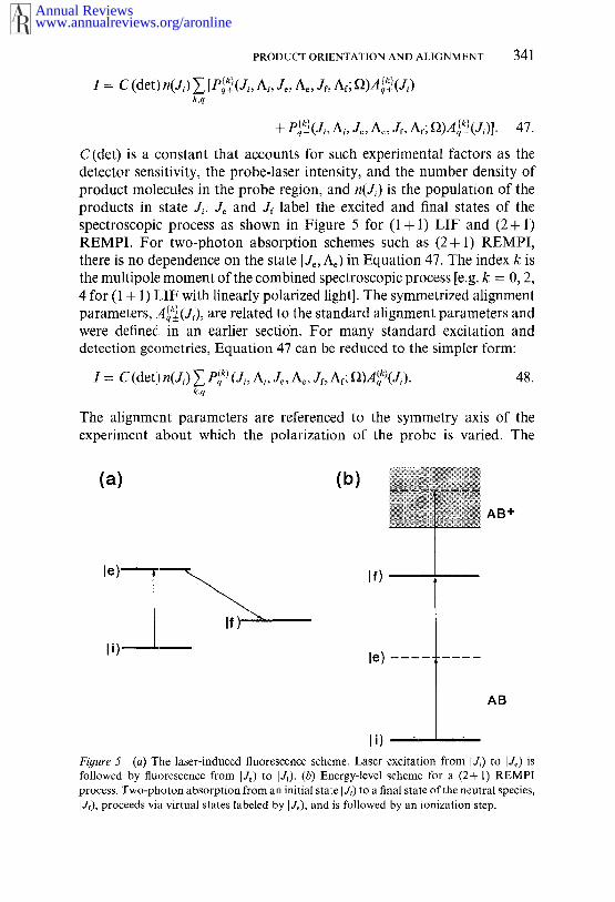
C(det) is a constant that accounts for such experimental factors as thedetector sensitivity, the probe-laser intensity, and the number density ofproduct molecules in the probe region, and n(Ji) is the population of theproducts in state J~. Je and Jf label the excited and final states of thespectroscopic process as shown in Figure 5 for (1 + 1) LIF and (2+ REMPI. For two-photon absorption schemes such as (2+ 1) REMPI,there is no dependence on the state I Je, Ae) in Equation 47. The index k isthe multipole moment of the combined spectroscopic process [e.g. k = 0, 2,4 for (1 + 1) LIF with linearly polarized light]. The symmetrized alignmentparameters, A~(J,.), are related to the standard alignment parameters andwere definedl in an earlier secti6n. For many standard excitation anddetection geometries, Equation 47 can be reduced to the simpler form:
I = C (det)n(J,.) ~ Pq(~) (J,., A,, Je, Ae, Jr, Af; I])A(q~)(J,-). 48.k,q
The alignment parameters are referenced to the symmetry axis of theexperiment about which the polarization of the probe is varied. The
(a) (b)
le)
li)
If)
AB+
AB
Fi#ure 5 (a) The laser-induced fluorescence scheme. Laser excitation from I J,.) to IJe) followed by tluorescence from IJ~) to IJ~). (b) Energy-level scheme for a (2+ 1) process. Two-photon absorption from an initial state I J~) to a final state of the neutral species,I Jr), proceeds via virtual states labeled by I J~), and is followed by’an ionization step.
www.annualreviews.org/aronlineAnnual Reviews

342 ORR-EWINQ & ZARE
Pq (Jr, At, Jr, Ac, Jr, At; ~) and P~(Jt, At, Jc, A~, Jr, Af; ~2) terms have beencalled line-strength moments and contain all the information pertainingto the spectral transition, such as its line strength and symmetry and theexperimental geometry (denoted here simply by the set of angles ~).Calculation of the P~k)(Ji, At, Je, A~, Jr, At; ~) and P~(Ji, A~,At; ~) values is involved, but Greene & Zare (81, 93) and Kummel et (89-91) have derived analytic forms for most cases of interest. The formsof the line-strength moments differ for the different types of spectro-scopic probe. Their calculation requires the evaluation of Wigner 6j and9j symbols, but computer programs are available for this task (82).
The principle behind the experimental determination of the alignmentparameters is that the line-strength moments change their values fordifferent spectroscopic transitions (e.g. for O, P, Q, R, and S branches) andfor different polarization angles, laser-propagation directions, fluorescencepolarizations, and fluorescence-detection directions (we refer to thesedirections as the experimental geometry). The variation of the P~qk)(J~, A~,
Jr, A~, Jt, At; ~) or P~(Ji, Ai, Je, A~, Jr, At; ~) terms can, however, becalculated using formulas summarized in references (81, 89-91, 93).Thus, by measuring the signal intensities, whether by chemilumin-escence, LIF, or REMPI, for different experimental geometries and/or spectral transitions, the alignment and orientation parameters can bededuced. The more geometries used, the more overdetermined thealignment parameters are and, thus, the more accurately they can bededuced (with more meaningful estimates of their associated errors). Fora system completely described by two alignment parameters, say A~o°)(J~)and A~2)(Jt), two experimental geometries or detection via two differentspectral branches are sufficient to determine the full M-state distribution.
Widespread use has been made of the above analysis in collisionaldynamics experiments. For example, as discussed earlier, investigatorsusing (1 ÷ 1) LIF with linearly polarized light have measured alignmentparameters for the NO product of the reaction of O(tD) with N~O (42,43), the OH products of the reactions of O(~D) with H=O (47) and (45), and the CO product of the reaction of O(~P) with CS (39-41).Numerous studies have examined the alignment of photodissociationproducts, particularly OH, NO, and CN (7, 112), and LIF detection wasused to study the alignment of CuF desorbed from a Cu (111) surfacefollowing association of surface-bound F atoms with Cu atoms (113).
Studies of N~ scattering from an Ag (111) surface have used (2+2)REMPI with linearly polarized light to measure the Nz alignment moments(114, 115), and elliptically polarized light to measure the orientationmoments (85). The same detection scheme has been used to study col-lisional relaxation of aligned Nz prepared by stimulated Raman pumping
www.annualreviews.org/aronlineAnnual Reviews

PRODUCT ORIENTATION AND ALIGNMENT 343
(116). The Nz scattering experiments have now been extended to includea (2 + 1) REMPI detection scheme (117), and we are currently using (2 REMPI of HC1 via the F~A state in our laboratory to probe the alignmentof this prodnct of the Cl(2ps/2)+ CH,~(I:3 = 1, J) reaction. The photolysisof CD3I has been studied using (2+ l) REMPI detection of CD3 (118-120) and also of I(ZP3/2) and I(~P1/2) (120). Houston and coworkers investigated the 248-nm photodissociation of 03 using (2+ 1) REMPIdetection of ()2(a lAg) via a I Hg Rydberg state combined with ion imaging.
The technJ.que developed by Jacobs & Zare (94) for analysing (1 + REMPI spectra to obtain orientation and alignment data differs sub-stantially in form from the methods of Greene & Zare (93) and Kummelet al (89-91). The differences arise because of the concerns of saturation,either in the first absorption step or in the ionization step, and the possi-bility of competition between ionization and stimulated emission to theground state. Such concerns do not arise in (2 + 1) REMPI because thetransition to the ground state is at twice the laser frequency, and becauseat the high laser powers used to drive the two-photon absorption step,ionization of’ the excited state is typically saturated. (1 + 1) REMPI hasnot yet been used to measure rotational alignment or orientation forthe products of a bimolecular reaction, but Jacobs et al (95, 122-125)demonstrated that NO inelastically scattered from a Pt (111) surface hasits rotational angular momentum preferentially aligned parallel to thesurface (cartwheel-type motion). NO desorbed from the surface, however,has J preferentially perpendicular to the surface (helicopter-type motion).
Hyperfine and Spin Depolarization
The degree of rotational alignment or orientation of a molecule can bealtered by coupling the rotational angular momentum, J, to external fieldsor to the nuclear or electronic spins of the molecule (80, 82, 87, 126-128).In the study of bimolecular reactions, such depolarization effects cansignificantly alter the alignment or orientation of prepared reagentsbecause, in general, reaction will not occur immediately upon preparationof the reagents. Likewise, coupling to external fields or intramolecularspin angular molnenta will affect the nascent polarization of J of reactionproducts during the time delay between reaction and detection. We con-centrate here on the effect of intramolecular couplings by first consideringthe effect of one nuclear spin, denoted by I, such as in OH or CH, andthen describing the effect of two nuclear spins encountered in moleculessuch as HF and HC1. We make the assumptions that (a) at the instant formation of molecules in an aligned or oriented ensemble, whether byoptical pumping or reaction, the rotational angular momentum isuncoupled from the spin angular momenta, but the different momenta
www.annualreviews.org/aronlineAnnual Reviews

344 ORR-EWlNG & ZARE
then couple to give a resultant F, and (b) the nuclear or electronic spinsare unpolarized at the instant of formation. We concentrate on nuclear-spin hyperfine-depolarization effects but also note that such considerationsapply to molecules with nonzero electronic spin S. In such cases, we candescribe the depolarization of the total angular momentum excluding spinN, which is caused by coupling to S, to give a resultant total angularmomentum d (129).
We can picture the depolarization of d in terms of the vector model ofangular momenta; d and I couple to give F, and then d precesses about Fso that the prepared direction of ,I in space is lost to some degree. Forvalues of d substantially larger than the magnitude of I, d and F willbe nearly parallel, and the hyperfine depolarization will be small. Formagnitudes of d close to or smaller than those of I, hyperfine depolar-ization can severely reduce the degree of orientation or alignment. Deri-vations of the extent of depolarization for a molecule with a single nuclearspin are given in terms of a state-multipole treatment by Blum (87), andin terms of a spherical-tensor-operator treatment by Zare (82). If therotational angular momentum distribution at the instant of formation ofthe aligned or oriented ensemble (time, t = 0) is described by multipolemoments of the rotational angular momentum spherical-tensor operator,(J~qk)),=o, then at some later time t, the multipole moments are given by
( J~qk)) , = G(~)( (Jq~)),=0, 49.
where G¢~)(t) is a time-dependent depolarization coe~cient:
G(~(t) = ~ (2F’+ 1)(2F+ 1) F
F,F’ (2I+1) J I COS[(EF,--EF)t/h].50.
In this equation, the EF are the eigenvalues of the hyperfine Hamiltonian,i.e. they are the energy levels arising from the coupling of the rotationaland nuclear spin angular momenta. They can be calculated from hyperfinecoupling constants. Note that the interaction between J and I does notmix multipole moments of J, but it does result in a decrease in their valueover time. The function G~)(t) is oscillatory and seldom returns to itsoriginal value of unity. The time-averaged value of G~)(t) is useful formeasurements made on a timescale longer than the oscillation period ofG~(t) and is given by
(G(~))--’--~’7~(2F+l)~{ FF(2/+ 1) F J J 5}2. 51.
Fano & Macek (80) discussed the effect of the couPling of two spins,
www.annualreviews.org/aronlineAnnual Reviews

PRODUCT ORIENTATION AND ALIGNMENT 345
and Altkorn et al (127, 130) derived an expression for the depolarizationcoefficient for depolarization by two nuclear spins, L and I2:
1G(k)(t) = (:211 + 1)(212 + 1) ~ (2F’+ 1)(2F+
× e~F;.(-- 1)F’+F;[(2Fi+ 1)(2Fi’+ 1)]1/2
,(~3c(F,),~Fi J F; I1COs[(E~F--E~,F,)t/h], 52.×~r,~’F; ~F F~ F~ J k
which has a l!ong-time averaged form:1
1)2 ~ (- 1)F~+F;[(2F,’+ 1)(2F,.’+ (G(k)) : (2I~ + 1)(212 + 1);(2F+ 1/2
53.
In a hierarchical-coupling scheme, J and |1 couple together to give F~, andFi subsequently couples to 12 to give the total angular momentum F. Inthe limit of a hierarchical-coupling scheme, F~ is a good quantum number.When such a hierarchical-coupling scheme is not applicable, ~ replacesas an intermediate quantum number. Assigning particular values to ~ isnot necessary because they serve only as labels to differentiate betweenstates. The states that diagonalize the hyperfine Hamiltonian are labeledby F and o~ in this instance. Orr-Ewing et al (131) calculated the time-dependence of the depolarization coefficients for HC1 for which lc~ = 3/2and In = 1/2. The calculation correctly predicted the observed time depen-dence of the REMPI intensity ratio for two laser polarizations.
Suppose that the product molecules are formed aligned by a reactioninitiated at tirae t = 0 and are probed at a later time t. Then three regimes ofhyperfine depolarization can be distinguished. If we ascribe a characteristictimescale to the hyperfine depolarization, denoted z, defined by
1-= IE~F--~¢F,I/h, 54.
the regimes are
1. t << z: The hyperfine depolarization can be neglected.2. t >> z: The hyperfine depolarization coefficient G(*)(t) can be replaced
www.annualreviews.org/aronlineAnnual Reviews

346 ORR-EWING & ZARE
by an average depolarization coefficient, (G(k)), as given in Equations51 and 53.
3. t ~ z: In this range, the time dependence of the depolarization becomessignificant.
Within Regime 3, for an essentially instantaneous event that occurs atone well-defined initial time, the hyperfine depolarization can be calculatedfrom Equation 50 or 52. Such a situation occurs, for example, in opticalpumping of molecules, or photodissociation. However, for a reactioninitiated at t = 0 and observed at a later time, t = t’, because individualreaction events occur with equal probability throughout the time range(assuming no depletion of reagents) and products formed at early timesundergo hyperfine depolarization for a longer time than those formed atlater times, we must use a cumulative hyperfine depolarization coefficient:
- G~k)(t) Gcum(t ) = 55.
Orr-Ewing et al (131) calculated this cumulative depolarization coefficientfor HC1 to illustrate the effects of depolarization on aligned reagents.
In the analysis of (1 + 1) LIF and (1 + 1) REMPI, we must also considerthe effect of hyperfine coupling to the rotational angular momentum ofthe intermediate state, [J~Me). The absorption of the first photon createsan excited state ensemble that is aligned or oriented and that can depolarizeprior to fluorescence or absorption of an ionizing photon. Such depolar-ization is of no concern in the (2+ 1) REMPI analysis because the ion-ization step is assumed to be saturated and thus independent of the align-ment of the intermediate state.
Saturation Effects
Many researchers using LIF to study reaction dynamics or kinetics assumethat the excited state population is proportional to the laser intensity. Thisassumption is generally valid at low laser intensities but fails as the laserpower increases; the nonlinear intensity behavior that is observed is termedsaturation. The high-peak intensities common with pulsed laser systemscan result in partial saturation of many atomic and molecular spectraltransitions. Under partial or complete saturation conditions, the depen-dence of the polarized LIF intensity on ground-state alignment and orien-tation moments deviates from the forms described previously. Altkorn &Zare (132) have used a rate-equation model to treat saturation effectsin LIF using both polarized laser excitation and polarization-resolvedfluorescence detection. For a cylindrically symmetric system, they show
www.annualreviews.org/aronlineAnnual Reviews

PRODUCT ORIENTATION AND ALIGNMENT 347
that in moderately saturated regimes, the fluorescence intensity dependson higher n’toments of the angular distribution than the A~04) alignmentmoment, which is the highest order moment that can be determined underunsaturated conditions. This sensitivity to higher-order moments makesthe polarization data difficult to interpret quantitatively. In the stronglysaturated limit, only the A~o2) alignment moment can be obtained. Janssenet al (133) extended the Altkorn & Zare (132) analysis to allow inversionof data within the regime of partial saturation to obtain alignment param-eters in the high-J limit and applied their analysis to experimental dataobtained by Engelke & Meiwes-Broer (34) on the Ca + F2 and Ca*+ reactions. Bergmann and coworkers (134) have demonstrated the appli-cation of saturated optical pumping and LIF detection to select single I MIlevels and to determine the population of single I MI states.
Altkorn & Zare (132) consider the high-Jlimit of rotational polarization,and they show that for a ground-state anisotropic distribution of angular-momentum vectors described the usual Legendre-polynomial expansiongiven in Equation 9. The LIF intensity for a two-level system is given by
.~ (2/~p +A=~)
x {1-exp[-(2fl,zp+Azl)AtzJ}. 56.
In this equation, n(Ji) is the total population of state [Ji); A21 is the usualEinstein coefficient for spontaneous emission; ~21 and/~12 are directional(differential) Einstein coefficients, which describe the interaction of direc-tional, polarized radiation with molecules that have a specific orientation;p is the density of radiation directed into the solid angle df~; and AtL isthe duration of the (assumed rectangular) laser pulse. In the limit of saturation, the exponential term can be replaced by the first two terms inits Taylor expansion, and a linear dependence of LIF signal on laserintensity is observed. When the absorption step is very strongly saturated,~12pAtL >> 1 (and//12P >> A21) and Equation 56 reduces to
1 = ½C (det) n (Ji) fd~[1 + a2P2 (cos 0)]e2, 57.
(terms with iLegendre polynomials of order greater than two integrate tozero). The experiment has become equivalent to performing an excited-state emission experiment because the ground state is detected in-dependently of its alignment and the laser polarization, so only thedetermination of Ag:) is possible. Note that polarization resolution of thefluorescence or dispersal and resolution of the fluorescence into P, Q, and
www.annualreviews.org/aronlineAnnual Reviews

348 ORR-EWING & ZARE
R branches becomes necessary to obtain any information about the ground-state alignment under fully saturated excitation conditions. Equation 57is independent of the Einstein B coefficients and laser power because halfthe molecules in the probed state are excited, regardless of their linestrengths.
Four-Wave Mixing Techniques as a Probe of Orientation and
Alignment
Spectroscopic probes that make use of four-wave mixing, such as coherentanti-Stokes Raman spectroscopy (CARS) (135, 136) and degenerate four-wave mixing (DFWM) (137-141), have proved valuable for the detectionof trace species in radiant, high-pressure (hostile) environments, such flames and plasmas, and have been applied, albeit in a limited number ofcases, to experimental studies of molecular dynamics (142-144). Attal-Tr6tout et al (145) gave analytical forms for the line strengths of CARStransitions, and their work has been extended by Aben et al (146), Bermanet al (147), Kupiszewska & Whitaker (148), Bervas et al (149), and Williamset at (150), who have calculated line strengths for DFWM. These cal-culations demonstrate that the intensity of four-wave mixing signal andthe degree of polarization of the signal beam depend strongly on thepolarizations of the three input beams and the rotational transition probed.The dependence on beam polarizations is a consequence of contributionsto the signal from polarization gratings that arise from coherent excitationof the M states of the probed molecules within the overlap region of thethree input laser beams. Williams et al (150) discussed the DFWM responsein terms of the zeroth-, first-, and second-rank spherical-tensor momentsof the angular-momentum distribution induced by the DFWM process.The calculations of Williams et al (150) should be readily extended understand the effects of an oriented or aligned sample on DFWM signalintensity. The detection of orientation and alignment by four-wave mixingis still in its infancy. We expect that this technique will prove very sensitiveto angular-momentum polarization and anticipate its application to thestudy of species for which LIF and REMPI are not convenient probes.
EXPERIMENTAL STRATEGIES FOR MEASURING
ROTATIONAL POLARIZATION FOR THE
PRODUCTS OF REACTIVE COLLISIONS
To determine the spatial anisotropy of reactive scattering experimentally,we need to break the spherical symmetry commonly encountered in bulbexperiments. This symmetry breaking has generally been achieved bymolecular beam methods, using either crossed-beam or beam-gas con-
www.annualreviews.org/aronlineAnnual Reviews

PRODUCT ORIENTATION AND ALIGNMENT 349
figurations. Recently, new techniques involving photolysis of a molecularprecursor a~ a source of translationally aligned, hot atoms have been used.This sectior.~ focuses on this approach, which was principally developed bythe groups of Bersohn, Hall, Hancock, Simons, and Zare, and on the useof molecular beams.
Crossed-Beam Experiments
The products of a simple chemical reaction of the type of Equation 1are scattered with azimuthal symmetry about the relative velocity of thereagents, k. Thus, whenever a measurement of angular momentum dis-tributions i~,~ desired, experiments are designed in which k is well defined.A crossed-beam experiment precisely defines the direction of k in thelaboratory t~rame (to within the uncertainty of the spread in velocities ofthe two beams and their angular divergence). The relative velocity providesan axis of cylindrical symmetry about which J-distribution measurementsgive the moments (P,,(J. ~)) directly. As discussed in subsequent sections,other experilmental techniques measure the distribution of J about alter-native labo::atory-frame symmetry axes, and the frame transformationbetween the fundamental symmetry axis k and the laboratory-frame axisresults in reduced sensitivity of the experiment. The crossed-beam methodfor the determination of product alignment has been used extensively byHerschbach and coworkers (12-15), Simons and coworkers (24-29), Engelke & Meiwes-Broer (34); the results of these studies were describedearlier.
Beam-Gas Experiments
In a beam-gas experiment, a beam of one reagent is directed into a thermalgas of the second reagent. The principal advantage of this experimentalconfiguration over crossed beams is the substantial gain in signal thataccompanies the use of a target gas. The beam axis Z defines an axis ofcylindrical symmetry in the experiment, and for a stationary ensemble oftarget gas molecules, also defines the direction of the relative velocity ofthe reactive collisions. The target gas is generally thermal at 300 K, andthe molecules of the gas move randomly with velocities that add to thebeam reagent velocity to give a resultant distribution of relative velocitiesthat differs from the stationary target-gas approximation. Zare and coworkers(22) showed that in the high-J limit, the Legendre moments of the dis-tribution of J about the beam axis can be factored using the azimuthallyaveraged addition theorem in terms of the Legendre moments about therelative velocity according to
<P.(J. ~)> = <P.(~. Z> <P.(J" 58.
www.annualreviews.org/aronlineAnnual Reviews
350 ORR-EWING & ZARE
The moments (P,(~" ~)) are experimentally determined, whereas (Pn(J’f~)) moments contain the desired dynamical information.
^remaining term, (P,,(k" Z)), is a so-called kinematic-blurring factor describes the extent to which the relative-velocity vector and the beam axiscoincide or differ as a consequence of the thermal motion of the targetgas. Clearly, if the kinematic-blurring factor is small in magnitude, thelaboratory-frame alignment parameters referenced to Z will be muchsmaller than the alignment parameters referenced to k. Using Monte-Carlo methods, Prisant et al (22) calculated the magnitude of the kine-matic-blurring factor with n = 2 for an effusive metal-atom beamimpinging on a thermal gas. Johnson et al (30) extended these calculationsto include supersonic and rotor-accelerated beam sources and developedtwo dimensionless parameters that determine the degree of the kinematicblurring. The conclusion of both groups was that the kinematic-blurringfactor is generally greater than 0.8; hence, the loss of alignment infor-mation resulting from beam-gas experiments rather than crossed-beamexperiments is small. The kinematic blurring is least for heavy, slow-moving targets or gases held at low temperature. Kettleborough & McKen-drick (151) gave an analytical expression for the distribution function forthe relative velocities of the reagents in a beam-gas experiment in whichthe beam is generated from an effusive source. These authors also describedhow to calculate the kinematic-blurring factor for n = 2 without the needfor Monte-Carlo sampling; a numerical integration is still required,however.
The beam-gas experimental method has been applied to several reactionsthat result in electronically excited products that then chemiluminesce;examples were given in an earlier section. As discussed previously, thepolarization of the chemiluminescence parallel and perpendicular to thebeam axis can be used to determine the alignment parameters. We reiteratethe principal limitation of this technique: determining quantum-state-resolved alignment parameters has proved possible in only one experi-mental case (23), and in that example, vibrational but not rotational stateresolution was achieved.
Photoinitiated Bulb Experiments With Translationally Hot
Atoms
The difficulties associated with obtaining quantum-state-resolved angularmomentum polarization data from crossed-beam and beam-gas experi-ments have led to the development of an alternative strategy that does notrely on beams, and hence is not hindered by the very low signal levels thatbeam experiments give. Studies have shown that the use of photo-dissociation of a molecular precursor to generate one translationally hot
www.annualreviews.org/aronlineAnnual Reviews

PRODUCT ORIENTATION AND ALIGNMENT 3 51
reagent can give vibrationally and rotationally resolved alignment infor-mation for the products of bimolecular reactions, when coupled with alaser detection method such as LIF or REMPI (39, 40, 43). The reactionscheme in these pump-and-probe experiments can be represented as
AX+hv --* A+X,
A+BC --~ AB÷C. 59.
The method for extracting AB rotational alignment relies on the A atomsbeing translationally hot and translationally aligned. By translationallyhot, we sirnply mean that the A-atom speeds are substantially in excess ofthose of the thermal target gas BC, which commonly occurs for photolyticsources of radicals and atoms. By translationally aligned, we mean thatthe distribution of A velocities is anisotropic in the laboratory frame.Translatioual alignment is readily achieved by photodissociation usinglinearly polarized light (we denote the polarization vector of the photolysislight by Evh). The center-of-mass angular distribution of photofragmentsA resulting from the photolysis of a molecule AX using linearly polarizedlight is (104)
w(ga, l~p,) = ~ { 1 + flP2(~A" l~ph)}, 60.
where fi is the well-known anisotropy parameter. ~ takes values in therange - 1 to 2, with//= - 1 corresponding to a sinz 0 distribution of VAabout Eph, and fi = + 2 corresponding to a cos2 0 distribution of VA aboutEph. In the limit of A having a much higher velocity than the thermal BC,the distribution of relative velocities for the reactive collisions is identicalto the distribution of A velocities given in Equation 60. However, as istrue for beam-gas reactions, the velocities of the BC targets are generallynot negligible, and allowance should be made for them. Green et al (39,40) developed an analytical form for the distribution of relative velocitiesarising from a single speed of A in a bulb experiment of the type describedhere that takes into account the thermal motion of BC. These authorsused numerical integration to account for the thermal motion of the AXand the spread in speeds of A from the photodissociation. Aoiz et al (152)and McKendrick and coworkers (38, 153) extended these calculationsusing analytical methods to account for the effect of the thermal motionof the AX photolysis precursor in addition to the thermal motion of theBC target; the latter authors obtained the compact expression for thedistribution of relative velocities:
w(k, Eph) dk d(f~" f;ph) = 9(k) { 1 + ~err(k)P2(f~" f;p,)} dk d(f~" ~), 61.
www.annualreviews.org/aronlineAnnual Reviews

352 ORR-EWING & ZARE
where flen(k) is an effective anisotropy parameter. This parameter has somevelocity dependence:
Is/2(kvA/p2)fleff(k) = fl I~/2(kva/P~), 62.
9(k) ~ /k3 exp [- (k2+ vZ~)/2p2]I1/~(kVA/p2), 63.2pz ~/vA
p2_ k~ T(m~x + m~c), 64.
where k~ is Boltzmann’s constant, m~c is the mass of the target gas, m~is the mass of the photolysis precursor, and I~/2 and Is/~ are modifiedspherical Bessel functions (154). McKendrick and coworkers (153) considered the consequences of Equation 61 for polarization measure-ments from hot-atom reactions. They examined the velocity dependenceof ~ for three very different mass combinations, the reactions H + Oz,O(3P) + CS, and O(3p) + H~. For the H + O~ reaction, ~ is virtually inde-pendent of k and is close to its limiting value of fl for all photolyticallygenerated H-atom velocities. Consequently, speed and angular variables inEquation 61 are essentially separable. For the O(3p)+ CS reaction, withoxygen atoms foxed by 355-nm photolysis of NOz in coincidence withNO(v = 0), the angular and speed terms are also approximately separable,although ~eff is reduced from B by 1 ~20%. For the reaction of O(;P)+ H~,however, the light target gas has such high thermal velocities that fl~ issubstantially reduced from fl, and angular and speed terms in Equation61 cannot be separated. The average reduction in anisotropy of the relativevelocity caused by thermal motion is greater than 60%. The consequencesof this reduction on polarization measurements in hot-atom reactions willbecome apparent from the following discussion.
The form of Equation 61, which links the laboratory frame, defined bythe cylindrical-symmetry axis Eph, to the relative-velocity frame, meansthat the frame transformation from center of mass to the laboratoryeliminates all the alignment moments except for the zeroth and secondorder terms. This limitation can be overcome by Doppler-resolvedmeasurements (vide infra) or by the novel three-dimensionally resolvedexperiments described later. The AAA theorem permits us to write
(e~O- £.~)) (e~(~- ~.~)) (~(]- i) 65.The kinematic-blurring factor in this case is given by
( Pz(~" ~) ) = ~fl~,-, 66.
www.annualreviews.org/aronlineAnnual Reviews

PRODUCT ORIENTATION AND ALIGNMENT 353
and using the connection between Legendre moments and alignmentparameters, we obtain (with vectors in parentheses denoting the referenceaxes for the alignment parameters)
A(o~)(l~p~) =1 (a> g/~ef~-A 0 (k). 67.
Knowledge’. of the anisotropy parameter for the AX photodissociation isclearly necessary to make the laboratory to center-of-mass frame conver-sion. Equation 67 shows the most obvious drawback to this technique:The factor of//err/5 associated with the center-of-mass to laboratory-frametransformation substantially decreases the limiting ranges that the align-ment can take in the laboratory frame, i.e. the best that can be hoped forin the laboratory frame is an alignment that is 40% of that in the center-of-mass frame. This limitation puts severe restrictions on the sensitivity ofbulb experiments that use translationally aligned atoms to the alignmentof reaction products and, as discussed above, is especially disadvantageousfor systems such as the reaction of O(~P)+H2. The technique of bulbexperiments that use velocity-aligned reagents, as described in this section,has been applied successfully to several reactions mentioned in a precedingsection.
Reaction Product Vector Correlations From the Analysis’ of
Doppler Profiles
Photoinitiated bulb reaction methods combined with sub-Doppler LIFdetection can give information about correlations between the vectors JAB,k, and k’, in addition to the A(02)(~) parameter. The use of Doppler-profileanalysis to extract vector correlations for the products of bimolecularreactions is similar to the bipolar-moment analysis of Dixon (155), whichis used widely in photodissociation studies (112). For bimolecular reac-tions, the bipolar-moment approach has been considered within two kine-matic regimes: (a) negligible center-of-mass velocity and (b) significantcenter-of-mass velocity.
Within Regime a, the Doppler profiles can be used to extract correlationsbetween the vectors k, k’, and JAa, including the second moment of thedifferential cross section (which can be written as a reactive anisotropyparameter, fl,.). The fitting and analysis of Doppler profiles within thisregime is similar to the procedure for photodissociation and yields anal-ogous results in terms of bipolar moments. As shown by Hancock andcoworkers (41, 58) and Brouard et al (44), Equation 9 of Dixon (155)gives the correlated distribution of reaction product velocities and angularmomenta, but the frame-transformation factor of 2/5 is replaced by oneof/~/5, with/~ being the anisotropy parameter for the photodissociation
www.annualreviews.org/aronlineAnnual Reviews

354 ORR-EWING & ZARE
of AX (the same kinematic-blurring effects as discussed in the precedingsection must be taken into account). This analysis results in a set of bipolarmoments, ~6~k)(k,, kr), similar to those used for photodissociation studies,which are rescaled from those used in photodissociation by a factor of/~/2for the moments with k = 2 and are referenced to the relative-velocityvector k rather than the transition dipole/~. Other than these changes,when the center-of-mass velocity is negligible, the analysis of reaction-product Doppler profiles is the same as that of Dixon for photodissociationproducts.
When the center-of-mass velocity cannot be neglected, the Doppler-profile analysis becomes somewhat more involved, but Brouard andcoworkers (44, 45, 152) showed that one can deduce vector-correlationinformation and differential-cross-section information that is more com-plete than the second moment of the scattering distribution. Theydeveloped an analysis based on velocity-dependent bipolar moments andFourier-transform methods and advocate using composite lineshapes con-structed from Doppler profiles taken at different experimental geometries.If correct linear combinations of the experimental profiles are coadded,the resultant composite profiles lose their dependence on certain bipolarmoments, and the laboratory-frame speed distribution of the AB reactionproduct can be deduced. Back simulation of this speed distribution withtrial functions can then be used to deduce features of the differential crosssection. Hall and coworkers (49) developed an equivalent analysis extract dynamical information from OH Doppler lineshapes for the pro-duct of the reaction of H with 02. The experimental Doppler profiles arefitted to a set of basis functions that are calculated for different scatteringangles and angular-momentum polarizations.
McCaffery and coworkers (97, 156-161) developed a variety of sub-Doppler and circular dichroism experiments that use optical-double-resonance methods to measure differential cross sections and vector cor-relations for inelastic scattering. In principle, the method could also beapplied to reactions. Rather than using molecular photodissociation toprepare translationally aligned reagents, they used a particular velocitysubgroup of the thermal BC molecules pumped by a narrow-bandwidthlaser to an excited state and monitored the change in the excited-statevelocity distribution caused by inelastic scattering. If excitation is per-formed in the wings of the Doppler profile for the thermal AB usingcircular polarization, excited state AB* forms with its velocity androtational-angular-momentum vectors preferentially parallel; however,excitation at the center of the Doppler profile prepares JAB preferentiallyperpendicular to the velocity. The sub-Doppler experiments performedwith circularly polarized lasers are sensitive to four vector quantities, VBc,
www.annualreviews.org/aronlineAnnual Reviews

PRODUCT ORIENTATION AND ALIQNMENT 355
JBc, VAB, and JAB (for inelastic scattering, BC and AB are the same moleculebefore and ’,after the scattering event), and McCaffrey’s group applied thesemethods to the measurement of a four-vector correlation for the scatteringof Li2 from Xe in bulb experiments (162, 163).
VARIATION OF ORIENTATION AND ALIGNMENTWITH SCATTERING ANGLE FROMPHOTOINITIATED BULB EXPERIMENTS
Together with Shafer, Simpson, and Xu (164-166) we have recentlydeveloped a novel method that provides detailed information about therotational anisotropy of reaction products at a quantum-state-resolvedlevel, and this rotational anisotropy can be measured for different productscattering angles. Thus, we have demonstrated that we can measure differ-ential cross sections that are I JABMAB)-state resolved. In this section, wefirst discuss the principles behind our technique and illustrate its implemen-tation. We then show how optical-state selection of one reagent can beused to approach the goal alluded to in the title of this section, I J~cM~c) IJABM~,B) specific differential cross sections.
The experimental method we use (164-166) has the following keyfeatures:
1. We use a photoinitiated reaction scheme.2. The reagent BC and precursor AX are diluted in helium and co-
expanded through a pulsed nozzle. This procedure ensures a trans-lationally cooled system.
3. AX is photolyscd to initiate reaction; the A atoms arc translationallyhot and "see" stationary targets BC because of the coexpansion.
4. In some’, experiments, we optically pump reagent BC to an excitedvibratio:aal state, with rotational state selection; otherwise, we assumethat BC is in a single vibrational and rotational state because of thecooling in the expansion. Either way, we are reacting state-selectedreagents.
5. After a delay of up to 200 ns after the photolysis laser pulse, weprobe the reaction product AB using a laser. The key to obtaining thedifferential cross section and resolving the rotational anisotropy is tomake a full velocity distribution measurement of the AB product withthree-dimensional resolution (164). As we discuss below, a three-dimen-sional measurement of the velocity can, under conditions of favorablekinematics and energetics, give a direct reading of the differential crosssection.
Shafer el: al (164) showed that for a state-to-state reaction performed
www.annualreviews.org/aronlineAnnual Reviews
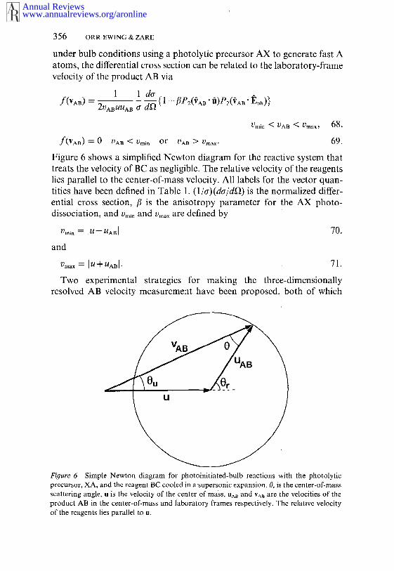
356 ORR-EWING & ZARE
under bulb conditions using a photolytic precursor AX to generate fast Aatoms, the differential cross section can be related to the laboratory-framevelocity of the product AB via
1 ldo-f(VAB) - 2VABUUAB ~r ~’~ { 1 + flP2(q AB " I])P2(qA~
Umin ~ /)AB < Uraax~ 68.f(VAB ) : 0 DAB < /)min or UAB > /) .... 69.
Figure 6 shows a simplified Newton diagram for the reactive system thattreats the velocity of BC as negligible. The relative velocity of the reagentslies parallel to the center-of-mass velocity. All labels for the vector quan-tities have been defined in Table 1. (1/a)(da/d~) is the normalized differ-ential cross section, /~ is the anisotropy parameter for the AX photo-dissociation, and/)min and/)max are defined
Vmin = I u- UAB I 70.
and
Umax = lu÷ua~l. 71.
Two experimental strategies for making the three-dimensionallyresolved AB velocity measurement have been proposed, both of which
Figure 6 Simple Newton diagram for photoinitiated-bulb reactions with the photolyticprecursor, XA, and the reagent BC cooled in a supersonic expansion. 0r is the center-of-mass
scattering angle, u is the velocity of the cent& of mass, u,~B and v~,~ are the velocities of the
product AB in the center-of-mass and laboratory frames respectively. The relative velocity
of the reagents lies parallel to u.
www.annualreviews.org/aronlineAnnual Reviews

PRODUCT ORIENTATION AND ALIGNMENT 357
make use of multiphoton ionization techniques to detect the AB product.In both cases, the reagents are prepared as in Steps 1-5 above. Thedetection rr~ethod of Shafer et al (165) uses a three-photon ionizationscheme, which we refer to as (1 + 1’+ 1") REMPI, and sub-Doppler band-width lasers and time-of-flight mass spectrometry (TOF/MS) of the ionsto probe the products in a velocity-selective fashion. The use of velocityresolution via time-of-flight mass spectrometry is also a key feature of themethod used by Simpson et al (166).
Mons & Dimicoli (167, 168) and others discussed the use of REMPIcoupled with time-of-flight (TOF) spectroscopy to measure velocity dis-tributions of photofragments. Ions are formed by (1 + 1) or (2 + 1) REMPIof photofragments in the extraction region of a linear time-of-flight massspectrometer. The TOF profile for any one mass corresponds to a one-dimensional projection of the photofragment velocity distribution ontothe TOF axis. The precise details of the inversion from time of flight tovelocity depend on the voltages used in the acceleration regions of thespectrometer and on whether the voltages are pulsed or continuous. Theideas developed for photodissociation experiments are also applicable tobimolecular reactions, and Simpson et al (166) demonstrated the use TOF/MS to obtain state-to-state resolved differential cross sections forthe reaction
Cl(2p3/2)-I-CH4(/33 1,J= 1)~ HCI(v’ -- 1,J’)+CH3, 72.
with J’ = 0, 1, 2, and 3.Shafer et al (165) used the velocity sensitivity of TOF measurements
obtain the Z axis velocity component of reaction products, having selectedthe X- and Y-axis components to be zero by their Doppler technique.Simpson et al (WR Simpson, AJ Orr-Ewing & RN Zare, unpublishedresults) have’, modified the traditional TOF method to give three-dimen-sional velocity resolution in a different manner, dubbed core-extraction.As the ion cloud, which is formed as a near-point source by the probe laserin a REMPI process, flies down the TOF tube, it expands outward becausemany of the ions have components of velocity carried over from thereactive event that are perpendicular to the Z axis. Simpson et al (WRSimpson, AJ Orr-Ewing & RN Zare, unpublished results) selected onlythose ions moving parallel or antiparallel (to within the instrumentalresolution) to the TOF axis by the use of a baffle placed in the TOF tubethat passes only those ions with little or no velocity component away fromthe TOF axis.
The exper:iments define an axis in the laboratory, which we denote byZ, selectively detect product molecules in a particular I VABJ,~B) quantumstate, and resOive the AB velocity along Z. The velocity resolution differs
www.annualreviews.org/aronlineAnnual Reviews

358 ORR-EWING & ZARE
from the Doppler profile method (41, 43~,5, 49, 58, 152) or the ion-imaging technique (119, 121, 169, 170) because the velocity resolutionalong Z is not a projection of a three-dimensional distribution onto a line,nor is it a two-dimensional projection onto a plane as is used in ionimaging. The measurement of VAB is a three-dimensionally resolved corethrough the velocity distribution. Thus we take the Z-axis component off(VAB), and the time-of-flight profiles that are recorded are a direct mappingof the differential cross section for the reaction. We can assign each pointon the time-of-flight profile to a particular scattering angle in the center-of-mass frame (to within the resolution of the instrument), and thus, study of the polarization dependence of each point on the profile gives therotational angular momentum anisotropy of the AB product as a functionof the scattering angle.
By changing the polarization of the probe laser(s) with respect to the axis, we have a method that is sensitive to the alignment moments of theAB referenced to the Z axis, i.e. we measure the distribution of JAB aboutVAB. We can convert this laboratory-frame alignment, or orientation, tothe frame of the relative velocities of the reagents, as is typically done forbimolecular reactions, but there is an equally simple frame transformationwe can make to relate the scattering-angle resolved alignment and orien-tation parameters to the velocity of the product AB in the center-of-massframe, UAB.
The angles and geometries needed are defined in Figure 7. Note thatseveral different center-of-mass velocities, u (and relative velocities, k), canresult in the measured laboratory velocity VAa for a single speed UAB, andthe possible values of u lie on a cone as shown in Figure 7. Thus wemust average over the azimuthal angle about VA~, and this averaging iscomplicated by the fact that unless Eph lies parallel to VAB, the azimuthalangle is not uniformly distributed. Using both the real parameters,A~)q(J), defined in Equation 26, and the complex parameters, sC~_~q(J),defined in Equation 27, we derived expressions for the orientation andalignment parameters in the frame of UAB. The frame transformation ofthe real alignment parameters requires the use of real rotation matricesand, thus, is a more complicated procedure than the transformation ofsC(~)q(J). We know the angles between the vA~ and UA~ frames (see Figure6) and can therefore interrelate the alignment parameters. We obtain therelationships
k
~(qk)(VAB ) : nq(Or, ~), O) ~ (k) d~q,(O)~q, (UAB), 73.q’=--k
k
= d~qq,(O)Aq , (UA~), 74.
www.annualreviews.org/aronlineAnnual Reviews

PRODUCT ORIENTATION AND ALIGNMENT 359
//
//
/UAB
Figure 7 Geometries and angles for analysis of the alignment and orientation of reactionproducts from photoinitiated bulb reactions.
with
fl q--0
Hq(Or, O, 0) /~P2 (cos 0r)dtqo(2>(0) dqt0(2>(®) . 75.i-+/~P2 (cos 0~) P2 (cos ®) P2 (cos -~ 0
We see from Equations 73-75 that the component, q, is restricted tovalues of q .’~ 2. If we consider a simple example of alignment parameterswith k = 2, a measurement of the five parameters ~’~k)(VAB) with q = 0,_+ 1, and _+ 2 allows inversion of Equation 73 or 74 to give the ~¢(q~’)(UAB)with k = 2. We can also calculate the relationship between alignmentparameters in the frames of VAB and u. We obtain very similar results toEquations 73-75 but with Hu(Or, ®, 0,) replaced by hu(O~, ®, 0~), where
1 q=0
hq(Or, 0, O) = ~d~q~o)(Ou) d~q~o)(®) . 76.1 +/~Pz(cos O,)P2(cos O) ~ 0
In Figure 8 we simulated differential cross section data using the core-extraction method for highly aligned HCI(v’ = 1, J’ = 1) obtained from
www.annualreviews.org/aronlineAnnual Reviews

360 ORR-EWING & ZARE
4
(b)
600 1000 1400 1800
Velocity (m/s)Figure8 Simulated core-extraction data for theHCl(v’ = 1,J’ = l) product of the reaction
of C1(2P3/2) with CH4(o3 = 1) using the measured differential cross section, and includingpossible alignment effects. The simulation is for HCI detection via the F(~A) state on theR(I) transition, with the probe laser polarized parallel and perpendicular to the photolysis
laser. (a) A~02) = ~ 2, and (b) A~0~1 = 1, with the long dashed line denoting the horizontally
polarized probe laser, the short dashed line denoting the vertically polarized probe laser, and
the solid line denoting the signal for no alignment.
the reaction of C1(2p3/2) with CH4(v3 = 1, J ~ 1). The simulations clearlydemonstrate that the method discussed here is extremely sensitive to pro-duct rotational alignment and orientation. The method is, on the whole,much more sensitive than the velocity-aligned experiments described earlierbecause the blurring caused by the center-of-mass frame to laboratory-frame transformation is significantly reduced. The principal disadvantageis that this sensitivity is at the expense of a loss of signal compared with
www.annualreviews.org/aronlineAnnual Reviews

PRODUCT ORIENTATION AND ALIGNMENT 361
collection ol~all the ions formed; however, compared with collection of LIFinto a small solid angle, the signal loss is not substantial. The alignmentparameters can be expressed in either the UAB or U (ll k) frames, and thuswe arrive at the same information that is contained within a bipolarmoment description of the rotational angular momentum distribution ofAB because’, we can correlate u (k), nAB, and JAB. The orientation andalignment parameters are, however, scattering-angle resolved.
If, as in the experiments of Simpson et al (166), a polarized excitationbeam is used in the state selection of the BC reagent, then the state-selectedBC is rotationally aligned in the frame of the polarization of the excitationlaser. This alignment is retained to some extent in the collision frame, i.e.with respect to the relative velocities of the reagents. We can write downa density-matrix representation of the MBc population distribution in theframe of reference of the excitation polarization, and this density matrixcan be tran~’;formed into the frame of the relative velocity. Thus we havea density matrix description of the MBc populations and coherences in theframe of k, and we measure the alignment parameters of the AB reactionproduct, which we can transform to the frame of k or UAB. We candetermine this alignment for different center-of-mass scattering angles. Wenote that for R(0) excitation and for the polarization of the excitationbeam parallel to the velocity-resolution axis, va~, a single state,IJ~ = 1, M~ = 0), is prepared in the collision frame for the formation offorward- or backward-scattered products.
The density-matrix elements in the collision frame for a photoinitiatedbulb experiment in which a one-dimensional velocity projection (Doppleror TOF profile) of the product velocities is made has only diagonal matrixelements because of cylindrical symmetry about the electric vector of thephotolysis laser (171). If the density-matrix elements are evaluated fora specific e~citation transition or are recast in terms of alignment andorientation parameters, the effect of averaging over the distribution of uis found to be much greater than for the experiments in which only oneVAB is resolved.
CONCLUSIONS
Developments in experimental reaction dynamics have reached the stagewhere spatial distributions of angular momentum vectors and velocitydistributions can be probed at a state-specific level. We have discussedmethods for quantifying the correlations between velocity and angularmomentum vectors and shown how these vector correlations are describedin terms of symmetrized operator moments termed orientation and align-ment parameters. The key to studying state specifically the correlations of
www.annualreviews.org/aronlineAnnual Reviews

362 ORR-EWING & ZARE
J is the use of optical probes because the multipolar nature of polarizedlight, be it linearly, circularly, or elliptically polarized, is naturally sensitiveto anisotropic distributions of J. The analytical techniques necessary toextract orientation and alignment parameters from spectral intensity infor-mation are firmly established in the literature. The more photons used inthe optical detection method, the higher the moments of the angularmomentum distribution that can be measured. We anticipate that four-wave-mixing methods will be applied to the probing ofanisotropic angularmomentum distributions, adding another valuable optical technique tothe more commonly used LIF and REMPI methods.
The number of reactions for which product alignment has been probedhas increased steadily over the past few years, and for photolyticallyinduced reactions studied under bulb conditions, the dependence of theproduct alignment on rotational quantum number can be investigated.Interpretation of the experimental data has yielded new insights intoelementary reaction mechanisms. No experinaents have, to our knowledge,probed the orientation of reaction products, and reaction product orien-tation remains a topic that warrants detailed investigation.
We have demonstrated that the dependence of product orientation andalignment on the center-of-mass scattering angle of the products can bededuced from a measurement of the full product velocity distribution (inthree dimensions). Optical state preparation of reagents can be used toselect a distribution of M states of the reagents that mostly keeps itsanisotropy on transformation to the collision frame, even for experimentsconducted under bulk conditions. These and other experimental develop-ments involving optical-detection methods demonstrate that bulb experi-ments, especially those in a cooled jet, can provide dynamic informationthat has not been forthcoming from crossed-beam and beam-gas experi-ments. We expect orientation and alignment measurements that are differ-ential in angle to be made soon. The prospect of I J, M) -, I J’, M’)-resolveddifferential cross sections promises to provide studies of chemical reactiondynamics with an unprecedented degree of detail.
ACKNOWLEDGMENTS
We thank WR Simpson, NE Shafer, and S Williams for many valuablediscussions. This work has been supported in part by the National ScienceFoundation under grant numbers CHE 89-21198 and CHE 93-22690.
Any Annual Review chapter, as well as any article cited in an Annual Review chapter,may be purchased from Annual Reviews Preprints and Reprints service.
1-800-347-8007; 415-259-5017; emaih [email protected]
www.annualreviews.org/aronlineAnnual Reviews
PRODUCT ORIENTATION AND ALIGNMENT 363Literature Cited
1. Child MS. 1974. Molecular CollisionTheory. London: Academic
2. Bernstein RB. 1982. Chemical Dyna-mics via Molecular Beam and LaserTechniques. Oxford: Clarendon
3. Bernstein RB, Herschbach DR, LevineRD. 1987. J. Phys. Chem. 91:5365-77
4. Simons JP. 1987. J. Phys. Chem. 91:5378-87
5. Levine RD, Bernstein RB. 1988. J.Phys. Chem. 92:6954-58
6. Levine RD. 1990. J. Phys. Chem. 94:8872-80
7. Houston PL. 1987. J. Phys. Chem. 91:5388-97
8. J. Phys. Chem. 1987.91:5365-55159. J. Chem. Soc. Faraday Trans. 1989.85:
925 137610. J. Chem. Soc. Faraday Trans. 1993.89:
1401-159211. Herschbach DR. 1987. Faraday
Discuss. Chem. Soc. 84:465-7812. Maltz C, Weinstein ND, Herschbach
DR. 1972. Mol. Phys. 24:133 5013. Hsu DSY, Herschbach DR. 1973.
Faraday Discuss. Chem. Soc. 55:116-19
14. Hsu DSY, McClelland GM, Hersch-bach DI~’,. 1974. J. Chem. Phys. 61:4927-28
15. Hsu DSY, Weinstein ND, HerschbachDR. 1975. Mol. Phys. 29:257-78
16. Freund SM, Fisk GA, Herschbach DR,Klemperer W. 1971. J. Chem. Phys. 54:2510-18
17. Mariella RP, Herschbach DR, Klem-perer W. 1974. J. Chem. Phys. 61: 4575-81
18. Vaccaro PH, Tsekouras AA, Zhao D,Leach CA, Zare RN. 1992. J. Chem.Phys. 96:2786-98
19. Noda C, Zare RN. 1987. J. Chem.Phys. 86:3968-77
20. Hartree WS, Simons JP, Gonzfilez-Urefia A. 1990. J. Chem. Soc. FaradayTrans. 86:1%20
21. Jonah CD, Zarc RN, Ottingcr C. 1972.J. Chem. Phys. 56:263-74
22. Prisant i~¢IG, Rettner CT, Zare RN.1981. J. (;’hem. Phys. 75:2222-30
23. Prisant ]~¢IG, Rettner CT, Zare RN.1982. Chem. Phys. Lett. 88:271-74
24. Rettner CT, Simons JP. 1978. Chem.Phys. Le~t. 59:178-81
25. Rettner CT, Simons JP. 1979. FaradayDiscuss. Chem. Soc. 67:329M2
26. Hennessy RJ, Simons JP. 1980. Chem.Phys. Le~t. 75:43-46
27. Hennessy RJ, Ono Y, Simons JP. 1980.Chem. Phys. Lett. 75:47-51
28. Hennessy RJ, Simons JP. 1981. Mol.Phys. 44:1027-34
29. Hennessy RJ, Ono Y, Simons JP. 1981.Mol. Phys. 43:181 92
30. Johnson K, Pease R, Simons JP. 1984.Mol. Phys. 52:955-68
31. Johnson K, Pease R, Simons JP, SmithPA, Kvaran A. 1986. J. Chem. Soc.Faraclay Trans. 82:1281-95
32. Tyndall GW, de Vries MS, Cobb CL,Martin RM. 1987. J. Chem. Phys. 87:5830-39
33. Tyndall GW, de Vries MS, Cobb CL,Martin RM. 1992. Chem. Phys. Lett.195:279-85
34. Engelke F, Meiwes-Broer KH. 1984.Chem. Phys. Lett. 108:132-37
35. Garay M, Mendndez M, Verdasco E,Castafio J, Gonzfilez-Urefia A. 1993. J.Phys. Chem. 97:5836-38
36. Men6ndez M, Garay M, Verdasco E,Gonz~ilez-Urefia A. 1993. J. Chem. Soc.Farada,v Trans. 89:1493-99
37. Li R-J, Han K-L, Li F-E, Lu R-C, HeG-Z, Lou N-Q. 1994. Chem. Phys. Lett.In press
38. van der Zande W, Zhang R, McKen-drick KG, Zare RN, Valentini JJ. 1991.J. Phys. Chem. 95:8205-7
39. Green F, Hancock G, Orr-Ewing AJ.1991. Faraday Discuss. Chem. Soc. 91:7%90
40. Green F, Hancock G, Orr-Ewing A J,Brouard M, Duxon SP, et al. 1991.Chem. Phys. Lett. 182:568-74
41. Costen ML, Hancock G, Orr-EwingAJ, Summerfield D. 1994. J. Chem.Phys. 100:2754-64
42. Brouard M, Duxon SP, Enriquez PA,Sayos R, Simons JP. 1991. Laser Chem.11: 265-72
43. Brouard M, Duxon SP, Enriquez PA,Sayos R, Simons JP. 1991. J. Phys.Chem. 95:8169-74
44, Brouard M, Duxon SP, Enriquez PA,Simons JP. 1992. J. Chem. Phys. 97:7414-22
45. Brouard M, Duxon S, Enriquez PA,Simons JP. 1993. J. Chem. Soc. FaradayTrans. 89:1435-42
46. Ben-Nun M, Brouard M, Simons JP,Levine RD. 1993. Chem. Phys. Lett.210:423-31
47. Sauder DG, Stephenson JC, King DS,Casassa MP. 1992. J. Chem. Phys. 97:952-63
48. Kleinermanns K, Linnebach E. 1986.Appl. Phys. B 36:203-6
49. Kim HL, Wickramaaratchi MA,Zheng X, Hall GE. 1994. J. Chem.Phys. In press
www.annualreviews.org/aronlineAnnual Reviews

364 ORR-EWING & ZARE
50. Alexander MH, Orlikowski R. 1984. ZChem. Phys. 80:1506-16
51. Dagdigian PJ, Alexander MH, Liu K.1989. J. Chem. Phys. 91:839M8
52. Alexander MH, Dagdigian PJ. 1984. &Chem. Phys. 80:4325-32
53. Alexander MH, Andresen P, Bacis R,Bersohn R, Comes FJ, et al. 1988. J.Chem. Phys. 89:1749-53
54. Mariella RP, LuntzAC. 1977. J. Chem.Phys. 67:5388-89
55. Mariella RP, Lantzch B, Maxson YT,Luntz AC. 1978. J. Chem. Phys. 69:5411-18
56. Murphy EJ, Brophy JH, Arnold GS,Dimpfl WF, Kinsey JL. 1978. J. Chem.Phys. 74:324-30
57. Andresen P, Luntz AC. 1980. J. Chem.Phys. 72:5842-50
58. Orr-Ewing AJ. 1991. Laser studies ofreaction dynamics. D. Phil. thesis.Oxford Univ.
59. Bronikowski MJ, Zare RN. 1990.Chem. Phys. Lett. 166:5-10
60. Hijazi NH, Polanyi JC. 1975. J. Chem.Phys. 63:2249-50
61. Hijazi NH, Polanyi JC. 1975. Chem.Phys. 11:1-16
62. Schatz GC, Kuppermann A. 1976. J.Chem. Phys. 65:4668-92
63. Blais NC, Truhlar DG. 1977. J. Chem.Phys. 67:1540-46
64. Alvarifio JM, Lagan/t A. 1991. J.Chem. Phys. 95:998-1005
65. Alvarifio JM, Lagan/t A. 1992. J. Phys.Chem. 96:3587-90
66. Alexander MH, Dagdigian P J,DePristo AE. 1977. J. Chem. Phys. 66:59-66
67. Alexander MH, Dagdigian PJ. 1977. J.Chem. Phys. 66:4126-32
68. Alexander MH, Davis SL. 1983. J.Chem. Phys. 79:227-38
69. Orlikowski T, Alexander MH. 1984. J.Chem. Phys. 80:4133-36
70. Khare V, Kouri D J, Hoffman DK.1981. J. Chem. Phys. 74:2275-86
71. Khare V, Kouri DJ, Hoffman DK.1981. J. Chem. Phys. 74:2656-57
72. Khare V, Kouri D J, Hoffman DK.1982. J. Chem. Phys. 76:4493-501
73. Prisant MG, Rettner CT, Zare RN.1984. J. Chem. Phys. 81:2699-712
74. McClelland GM, Herschbach DR.1987. J. Phys. Chem. 91:5509-15
75. Case DA, Herschbach DR. 1975. Mol.Phys. 30:1537-64
76. Case DA, Herschbach DR. 1976. J.Chem. Phys. 64:4212-22
77. Barnwell JD, Loeser JG, HerschbachDR. 1983. J. Phys. Chem. 87:2781-86
78. Case DA, Herschbach DR. 1978. J.Chem. Phys. 69:150-58
79. Case DA, McClelland GM, Hersch-bach DR. 1978. Mol. Phys. 35:541-73
80. Fano U, Macek JH. 1973. Rev. Mod.Phys. 45:553-73
81. Greene CH, Zare RN. 1982. Annu. Rev.Phys. Chem. 33:119-50
82. Zare RN. 1988. Angular Momentum.Understanding Spatial Aspects in Chem-istry and Physics. New York: Wiley
83. Hasselbrink E, Waldeck JR, Zare RN.1989. Chem. Phys. 126:191-200
84. Black JF, Waldeck JR, Zare RN. 1990.J. Chem. Phys. 92:3519-38
85. Sitz GO, Kummel AC, Zare RN, TullyJC. 1988. J. Chem. Phys. 89:2572-82
86. Varshalovich DA, Moskalev AN,Khersonskii VK. 1989. Quantum Theoryof Angular Momentum. Singapore:World Scientific
87. Blum K. 1981. Density Matrix Theor.vand Applications. New York: Plenum
88. Fano U. 1957. Rev. Mod. Phys. 29: 74-93
89. Kummel AC, Sitz GO, Zare RN. 1986.J. Chem. Phys. 85:6874.97
90. Kummel AC, Sitz GO, Zare RN. 1988.J. Chem. Phys. 88:7357-68
91. Kummel AC, Sitz GO, Zare RN. 1988.J. Chem. Phys. 88:6707-32
92. Hertel IV, Stoll W. 1978. Adv. At. Mol.Phys. 13:113-228
93. Greene CH, Zare RN. 1983. J. Chem.Phys. 78:6741-53
94. Jacobs DC, Zare RN. 1986. J. Chem.Phys. 85:5457-68
95. Jacobs DC, Madix RJ, Zare RN. 1986.J. Chem. Phys. 85:5469-79
96. Docker MP. 1988. Chem. Phys. 125:185-210
97. Rowe MD, McCaffcryAJ. 1979. Chem.Phys. 43:35 54
98. Bain A J, McCaffery A J, Procter M J,Whitaker BJ. 1984. Chem. Phys. Lett.110:663-65
99. Bain AJ, M¢Caffery AJ. 1984. Chem.Phys. Lett. 105:477-79
100. BainAJ, McCafferyAJ. 1984. J. Chem.Phys. 80:5883-92
101. BainAJ, McCaffery AJ. 1985. J. Chem.Phys. 83:2627-31
102. Bain AJ, McCaffery AJ. 1985. J. Chem.Phys. 83:263240
103. Bain AJ, McCaffery AJ. 1985. J. Chem.Phys. 83:2641-45
104. Zare RN. 1972. Mol. Photochem. 4: 1-37
105. Bergmann K. 1988. In Atomic andMolecular Beam Methods, ed. G Scoles,1: 293-344. New York: Oxford Univ.Press
106. Taatjes CA, Stolte S. 1993. J. Chem.Soc. Faraday Trans. 89:1551-65
www.annualreviews.org/aronlineAnnual Reviews

PRODUCT ORIENTATION AND ALIGNMENT 365107. Hefter U, Bergmann K. 1988. See Ref.
105, pp. 193-253108. Waldeck JR, Kummel AC, Sitz GO,
Zare RN. 1989. J. Chem. Phys. 90:4112-14
109. Chen K, Yeung ES. 1979. J. Chem.Phys. 70:1312-19
110. Dubs M, Bruhlmann U, Huber JR.1986. J. (?hem. Phys. 84:3106-19
lll. Docker MP. 1989. Chem. Phys. 135:405-21
112. Hall GE., Houston PL. 1989. Annu.Rev. Phys. Chem. 40:375-405
I 13. Naher U, Bracket A, Chert XR, JakobP, Wanner J. 1991. J. Phys. Chem. 95:8376-79
114. Sitz GO, Kummel AC, Zare RN. 1987.J. Chem. Phys. 87:3247-49
115. Sitz GO, Kummel AC, Zare RN. 1988.J. Chem. Phys. 89:2558 71
116. Sitz GO, Farrow RL. 1990. In Proc.12th Combustion Res. Conf., Off. BasicEnergy Sci., US Dep. Energy, TahoeCity, Calif.
117. Hanisco TF, Yah C, Kummel AC.1992. J. Phys. Chem. 96:2982 93
l 18. Powis I, Black JF. 1989. J. Phys. Chem.93:2461-70
119. Janssen MHM, Parker DH, Sitz coO,Stolte S, Chandler DW. 1991. J. Phys.Chem. 95:8007-13
120. Ogorzalek-Loo R, Haerri HP, HallGE, Houston PL. 1989. J. Chem. Phys.90:4222-36
121. Suits AG, Miller RL, Bontuyan LS,Houston PL. 1993. J. Chem. Soc. Fara-day Trans. 89:1443-47
122. Jacobs DC, Kolasinski KW, Madix R J,Zare RN. 1987. J. Chem. Phys. 87:5038-39
123. Jacobs DC, Kolasinski KW, Madix R J,Zare RN. 1989. J. Chem. Soc. FaradayTrans. 85:1325-35
124. Jacobs DC, Kolasinski KW, Shane SF,Zare RN. 1989. J. Chem. Phys. 91:3182-95
125. Jacobs DC, Zare RN. 1989. J. Chem.Phys. 91:3196-207
126. Madden PA. 1975. Chem. Phys. Lett.35:521-24
127. Altkorn R, Zare RN, Greene CH.1985. MoL Phys. 55:1-9
128. Yah C, lg.ummel AC. 1993. J. Chem.Phys. 98:6869-82
129. Reid KL. 1993. Chem. Phys. Lett. 215:25-30
130. Altkorn R. 1984. Studies of molecularrotation in elementary reactions utilizinylaser tecllniques. PhD thesis. StanfordUniv.
131. Orr-Ewing AJ, Simpson WR, RakitzisTP, Zare RN. 1994. lsr. J. Chem. 34:95 102
132. Altkorn R, Zare RN. 1984. Annu. Rev.Phys. Chem. 35:265-89
133. Janssen MHM, Parker DH, Stolte S.1987. Chem. Phys. 113:357-82
134. Hefter U, Ziegler G, Mattheus A, Fis-cher A, Bergmann K. 1986. J. Chem.Phys. 85:286-302
135. Eckbreth AC. 1988. Laser Diagnosticsfor Combustion Temperature Species.Cambridge, MA: Abacus
136.Valentini JJ. 1985. In SpectrometricTechniques, ed. GA Vanasse, pp. 1-61.New York: Academic
137. Abrams RL, Lam JF, Lind RC, SteelDG, Liao PF. 1983. In Optical PhaseConjugation, ed. RA Fisher, pp. 211-84. New York: Academic
138. Ewart P, O’Leary SV. 1986. Opt. Lett.11:279-81
139. Farrow RL, Rakestraw DJ. 1992. Sci-ence 257:1894-900
140. Williams S, Green DS, Sethuraman S,Zare RN. 1992. J. Am. Chem. Soe. 114:912~30
141. Green DS, Owano TG, Williams S,Goodwin D, Zare RN, Kruger CH.1993. Science 259:1726-29
142.Valentini JJ, Gerrity DP, Phillips DL,Nieh J-C, Tabor KD. 1987. J. Chem.Phys. 86:6745-56
143. Aker PM, Valentini JJ. 1993. Int. Rev.Phys. Chem. 12:363-90
144. Zhang Q, Kandel SA, Wasserman AW,Vaccaro PH. 1992. J. Chem. Phys. 96:1640~43
145.Attal-Tr6tout B, Monot P, Mtiller-Dethlefs K. 1991. Mol. Phys. 73: 1257-93
146. Aben I, Ubachs W, van der Zwan G,Hogervorst W. 1993. Chem. Phys. 169:113-28
147. Berman PR, Steel DG, Khitrova G, LiuJ. 1988. Phys. Rev. A 38:252-62
148. Kupiszewska D, Whitaker BJ. 1993. J.Chem. Soc. Faraday Trans. 89: 2951-56
149. Bervas H, Le Boiteux S, Labrunie L,Attal-Tr6tout B. 1993. Mol. Phys. 79:911-41
150. Williams S, Zare RN, Rahn LA. 1994.J. Chem. Phys. In press
151. Kettleborough JA, McKendriek KG.1991. J. Phys. Chem. 95:8255-63
152. Aoiz F J, Brouard M, Enriquez P,Sayos R. 1993. J. Chem. Soc. FaradayTrans. 89:1427-34
153. Gilbert EP, Maitland G, Watson A,McKendrick KG. 1993. J. Chem. Soc.Faraday Trans. 89:1527-31
154. Abramowitz M, Stegun IA. 1972.Handbook of Mathematical Functions.New York: Dover
www.annualreviews.org/aronlineAnnual Reviews

366 ORR-EWING & ZARE
155. Dixon RN. 1986. J. Chem. Phys. 85:1866-79
156. McCaffery A J, Procter M J, WhitakerBJ. 1986. Annu. Rev. Phys. Chem. 37:223-44
157. McCaffery AJ. 1987. J. Phys. Chem. 91:5451-55
158. McCaffery AJ, Reid KL, Whitaker BJ.1988. Phys. Rev. Lett. 61:2085-87
159. Fell CP, McCaffery AJ, Reid KL, Tick-tin A. 1991. J. Chem. Phys. 95: 4948-57
160. Reid KL, McCaffery AJ. 1991. J.Chem. Phys. 95:4958-65
161. Reid KL, McCaffery AJ. 1992. J.Chem. Phys. 96:5789-96
162. Collins TLD, McCaffery AJ, WynnMJ. 1991. Faraday Discuss. Chem. Soc.91:91-96
163. Collins TLD, McCaffery AJ, WynnMJ. 1991. Phys. Rev. Left. 66:137-40
164. Shafer NE, Orr-Ewing AJ, SimpsonWR, Xu H, Zare RN. 1993. Chem.
Phys. Lett. 212:155 62165. Shafer NE, Xu H, Tuckett RP, Sprin-
ger M, Zare RN. 1994. J. Phys. Chem.98:3369 78
166. Simpson WR, Orr-Ewing A J, Zare RN.1993. Chem. Phys. Lett. 212:163-71
167. Mons M, Dimicoli I. 1986. Chem. Phys.Lett. 131:298-302
168. Mons M, Dimicoli I. 1989..L Chem.Phys. 90:4037-47
169. Chandler DW, Houston PL. 1987. J.Chem. Phys. 87:1445-47
170. Chandler DW, Thoman JW, Sitz GO,Janssen MHM, Stolte S, Parker DH.1989. J. Chem. Soc. Faraday Trans. 85:1305-9
171. Orr-Ewing AJ, Zare RN. 1994. InChemical Dynamics and Kinetics ofSmall Free Radicals, ed. K Liu, AWagner. Singapore: World Scientific.In press
172. Jalink H, Parkcr DH, Stolte S. 1986. J.Chem. Phys. 85:5372-73
www.annualreviews.org/aronlineAnnual Reviews