oriana - gov uk · oriana sailed from new york at 2007(utc – 4 hours) on 23 september 2000, for...
TRANSCRIPT
Report on the investigation of
wave damage to the
passenger cruise ship
Oriana
in the North Atlantic Ocean
28 September 2000
Marine Accident Investigation BranchFirst Floor
Carlton HouseCarlton PlaceSouthampton
United Kingdom SO15 2DZ
Report No 36/2002November 2002

Extract from
The Merchant Shipping
(Accident Reporting and Investigation)
Regulations 1999
The fundamental purpose of investigating an accident under these Regulations is todetermine its circumstances and the cause with the aim of improving the safety of lifeat sea and the avoidance of accidents in the future. It is not the purpose to apportionliability, nor, except so far as is necessary to achieve the fundamental purpose, toapportion blame.

CONTENTS
Page
GLOSSARY OF ABBREVIATIONS, ACRONYMS AND TERMS
SYNOPSIS 1
SECTION 1 - FACTUAL INFORMATION 2
1.1 Particulars of Oriana and accident 21.2 Narrative 31.3 Injuries to personnel and damage 71.4 Onboard weather monitoring 91.5 Storm warnings 141.6 Ship’s motion and wave heights 141.7 The windows 181.8 Window defects 281.9 Storm covers 311.10 Vessel condition 341.11 Action taken regarding yacht in distress 341.12 Action taken following the accident 34
SECTION 2 - ANALYSIS 40
2.1 Window design 402.2 Window defects 402.3 Failure mechanism 432.4 Storm avoidance 432.5 Safety considerations 452.6 Risk to personnel 462.7 Storm covers 462.8 Damage repairs 472.9 Remedial action 482.10 Actions taken following the accident 482.11 Trends in ship’s window design 48
SECTION 3 - CAUSE 49
3.1 Immediate cause: 493.2 Contributing factors: 493.3 Other findings: 50
SECTION 4 - RECOMMENDATIONS 52
Appendix
Figure 1 Diagram showing Oriana’s deck layout
Figure 2 Extract of BA Chart 4004 showing the tracks of Oriana and thedepression

Figure 3 Photograph of distorted bulkhead
Figure 4 Photograph of damaged ceiling
Figure 5 Photograph of damaged bathroom module
Figure 6 MO Surface Analysis for 1200 on 27 September 2000
Figure 7 MO Surface Analysis for 1200 on 28 September 2000
Figure 8 Photograph showing waves coming from the port quarter
Figure 9 Photograph of a wave breaking
Figure 10 Photograph of a ploom of spray on the port side at deck 7
Figure 11 Photograph of a wave of a similar height to deck 7
Figure 12 Diagram showing Significant Wave Heights for 00Z on 28 September2000
Figure 13 Diagram showing Significant Wave Heights for 12Z on 28 September2000
Figure 14 Drawing of Het Anker Type 507 window
Figure 15 Drawing of Het Anker Type 606 window
Figure 16 Welding instructions issued by Het Anker
Figure 17 Photograph showing the positions of the damaged windows
Figure 18 Diagram showing the positions of the damaged cabins
Figure 19 Photograph of glass pane found intact
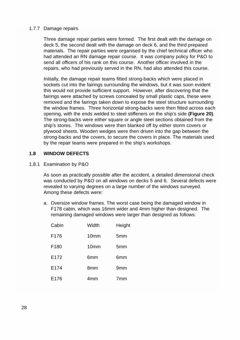
Figure 20 Photograph of a temporary repair to a damaged window
Figure 21 Diagram showing gap caused by poor fitting gasket
Figure 22 Diagram of the securing arrangements for storm covers
Figure 23 Photograph of a storm cover in position
Figure 24 Photograph of ruptured sockets
Figure 25 Diagram of a retaining plate
Figure 26 Photograph of window fitted with retaining plates
Figure 27 Lloyd’s Register Marine Technical Notice
Figure 29 Lloyd’s Register survey procedure for windows at Het Anker
Figure 28 Illustration of hogging

GLOSSARY OF ABBREVIATIONS AND ACRONYMS
BA - British Admiralty
BSMA 25 - British Standard - Marine Series No 25
ETA - Estimated Time Of Arrival
FWOC - Fleet Weather and Oceanographic Centre
ISO - International Standards Organisation
IMO - International Maritime Organisation
kW - Kilowatts
kt - knot
m - metres
mb - millibar
MCA - Maritime and Coastguard Agency
MSA - Marine Safety Agency
MHz - Megahertz
mm - millimetres
MO - Meteorological Office
MRCC - Maritime Rescue Co-ordination Centre
nm - nautical mile
NWS - National Weather Service
OOW - Officer of the Watch
RFI - Radio France Internationale
RN - Royal Navy
US - United States
UTC - Universal Co-ordinated Time

GLOSSARY OF TERMS
B-0 fire rating - Capable of preventing the passage of fire to the end of the first halfhour of a standard fire test.
Hogging - The deviation of the keel from the horizontal when the keel isconcave downward, ie the upper decks are in tension and the keel isin compression. (Figure 28)
Hove-to - Due to the stress of the weather a vessel is manoeuvred so as toride out the storm in the most comfortable position. This is usuallyachieved by heading into the sea and swell at very slow speed.
Mullion - A vertical support in a window frame.
Yaw - The unavoidable oscillation of the ship’s head either side of thecourse being steered or when at anchor, due to wind and waves.
SYNOPSIS
At 1410 UTC on 28 September 2000, the passenger cruise ship Oriana was onpassage from New York to Southampton at a speed of about 19.5 knots when she wasstruck by a large wave amidships on her port side. As a result three cabin windows ondeck 5, and three cabin windows on deck 6 were breached, injuring the occupants andcausing extensive damage to the cabins and fittings. Storm covers had been fitted tothe damaged windows on deck 5 but these were also breached.
The ship was experiencing storm force conditions and very high seas. Although thedesign of the windows met the strength requirements of BSMA 25, the UK standardfor ships’ windows, examination of the damaged windows and the remainingwindows on the affected decks revealed the presence of numerous defects. Thestrength of the windows was significantly reduced by these defects, making themvulnerable to wave damage. Although the exact sources of the defects cannot bedetermined, they are likely to have originated either during manufacture or in theshipyard during, or following, installation. It is not known if the impact of the waveexceeded the designed strength of the windows. It is believed the storm coverswere breached because their mounting arrangements failed.
This report makes recommendations to the manufacturer, shipbuilder, andclassification society aimed at improving their quality control procedures.Recommendations to the MCA are aimed at providing clarification on the use andstrength requirements for storm covers, and ensuring that standards for ship’s windowdesign remain applicable.
1

2
SECTION 1 - FACTUAL INFORMATION
1.1 PARTICULARS OF ORIANA AND ACCIDENT
Vessel details Oriana
Registered owner : P&O Cruises Limited (now P&O Princess Cruises International Limited)
Port of registry : London
Flag : UK
Type : Passenger Cruise Ship
Built : Meyer Werft Shipbuilders, Papenberg, Germany 1995
Classification society : Lloyd’s
Construction : Steel
Length overall : 225.34 metres (between perpendiculars)
Gross tonnage : 69,153
Engine power and/or type : Centre - 23850kWWing -15900kW
Service speed : 24 knots
Other relevant info : Bow and stern thrusters, 2 controllable pitchpropellers
Accident details
Time and date : 1410 UTC on 28 September 2000
Location of incident : 49°15N, 022°50W, 570 miles west-south-westof Cork, Eire
Persons on board : Crew: 783
Passengers : 1524
Injuries/fatalities : One crew and six passengers suffered cuts andbruises, some passengers suffered from shockDamage : Six windows on the port side werebreached. Water ingress caused substantial damageto the six passenger cabins affected. Lesser damagewas caused to adjacent cabins, corridors andstairways.
3
Unless specified, times are UTC. All courses are true. The decks on Orianaare both numbered and named. Throughout this report ‘E’ refers to Ellora and‘F’ refers to Formosa decks. A deck layout is shown at Figure 1. It should benoted that E deck corresponds to deck 6 and F deck to deck 5.
1.2 NARRATIVE
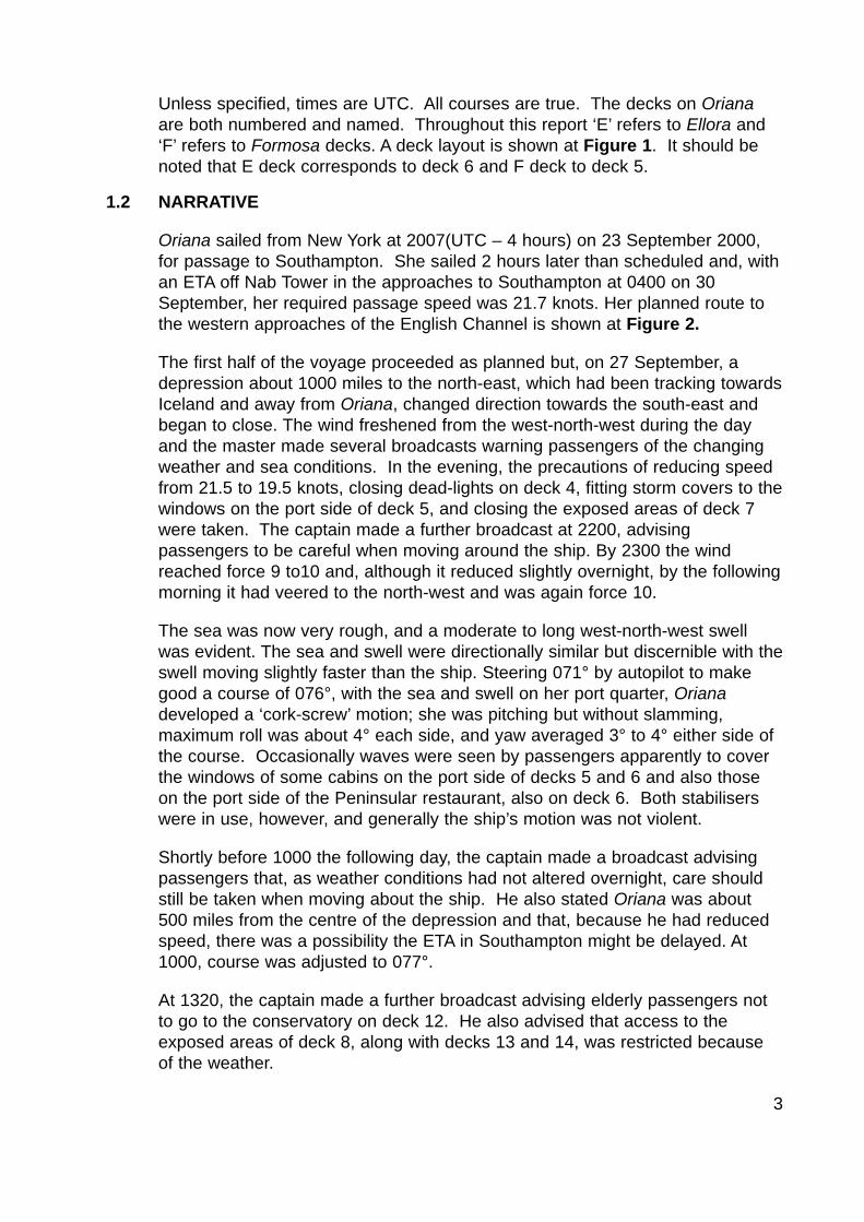
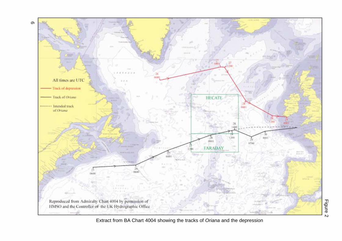
Oriana sailed from New York at 2007(UTC – 4 hours) on 23 September 2000,for passage to Southampton. She sailed 2 hours later than scheduled and, withan ETA off Nab Tower in the approaches to Southampton at 0400 on 30September, her required passage speed was 21.7 knots. Her planned route tothe western approaches of the English Channel is shown at Figure 2.
The first half of the voyage proceeded as planned but, on 27 September, adepression about 1000 miles to the north-east, which had been tracking towardsIceland and away from Oriana, changed direction towards the south-east andbegan to close. The wind freshened from the west-north-west during the dayand the master made several broadcasts warning passengers of the changingweather and sea conditions. In the evening, the precautions of reducing speedfrom 21.5 to 19.5 knots, closing dead-lights on deck 4, fitting storm covers to thewindows on the port side of deck 5, and closing the exposed areas of deck 7were taken. The captain made a further broadcast at 2200, advisingpassengers to be careful when moving around the ship. By 2300 the windreached force 9 to10 and, although it reduced slightly overnight, by the followingmorning it had veered to the north-west and was again force 10.
The sea was now very rough, and a moderate to long west-north-west swellwas evident. The sea and swell were directionally similar but discernible with theswell moving slightly faster than the ship. Steering 071° by autopilot to makegood a course of 076°, with the sea and swell on her port quarter, Orianadeveloped a ‘cork-screw’ motion; she was pitching but without slamming,maximum roll was about 4° each side, and yaw averaged 3° to 4° either side ofthe course. Occasionally waves were seen by passengers apparently to coverthe windows of some cabins on the port side of decks 5 and 6 and also thoseon the port side of the Peninsular restaurant, also on deck 6. Both stabiliserswere in use, however, and generally the ship’s motion was not violent.
Shortly before 1000 the following day, the captain made a broadcast advisingpassengers that, as weather conditions had not altered overnight, care shouldstill be taken when moving about the ship. He also stated Oriana was about500 miles from the centre of the depression and that, because he had reducedspeed, there was a possibility the ETA in Southampton might be delayed. At1000, course was adjusted to 077°.
At 1320, the captain made a further broadcast advising elderly passengers notto go to the conservatory on deck 12. He also advised that access to theexposed areas of deck 8, along with decks 13 and 14, was restricted becauseof the weather.

4
At about 1410, a large wave struck amidships on the port side, breaching threewindows fitted with storm covers on deck 5, and three windows without stormcovers on deck 6. Six passengers and one crew, who were in the cabins at thetime, were injured, either by flying glass or by being knocked over by the forceof the water. On escaping from his cabin, one passenger deliberately activateda fire alarm in the corridor which sounded on the bridge and indicated a fire inthe vicinity of cabin F178. Immediately the coxswain left the bridge toinvestigate. When he arrived at the scene, he contacted the OOW promptly viahand-held VHF radio, and requested the assistance of the ship’s assessmentparty. The OOW was also notified by reception that water was running betweendecks 5 and 6.
At 1412, a broadcast was made directing the assessment party to proceed tocabin F178 on deck 5. The assessment party established the nature of thedamage quickly and informed the captain, who reduced speed immediately andmade a warning broadcast which included:
I have sustained some broken windows on deck 5 and 6 and I’m going toturn the ship around into the wind to ease the stress. I would like everybodyonboard who is not taking part in dealing with the situation to please sitdown on the deck, while I turn the ship across the sea….
He then turned the ship into sea to a course of 310° at between 3 to 5 knots.
To put the ship’s company at a high state of readiness until a thoroughassessment of the damage had been completed, the crew-alert signal wassounded at 1428. This was followed by a broadcast explaining the meaning ofthe signal and advising passengers they were not required to take any action.
By 1458, the extent of the damage had been determined and the captaindecided to relax from crew alert but to remain hove-to until temporary repairswere complete. To keep the passengers and crew appraised he made abroadcast which included the following:
The ship’s company are about to be piped down from their crew alert, withthe exception of those who are carrying out their duties with the damage onthe port side of F deck and E deck. For the attention of passengers we aregoing to have to carry out some rather lengthy repairs including weldingsome brackets to the ship’s side which will take some time. I intend for theimmediate future to remain on this heading with the ship going into wind asthis will be the least problematical heading and motion of the ship for thosecarrying out the repairs at the moment…… the ship is going to remainmoving like this, ie pitching slightly for some time whilst we carry out repairs.You may again start to move around the ship but please be aware that thereis some pitching and I would like you to be extremely careful in the way youwalk around and be alert that at some stage in the future we will be turningthe ship through the wind again, at which time I will give you plenty ofnotice….

5
Oriana deck layout
Fig
ure
1
These three on deck 5
These three on deck 6
Funnel
E deck
Waterline
F deck
6
Extract from BA Chart 4004 showing the tracks of Oriana and the depression
Fig
ure
2
7
To minimise deck movement during the window repair, Oriana remained hove-to.Repairs were completed at 1745, and at 1800 the captain made a broadcastwhich included:
I am pleased to tell you that our repairs have now been completed and that Iintend getting under way again at 6.15 this evening. At that time, I will bemaking a turn to starboard and increasing speed to about 15 knots andextending our stabilisers which I have had to house since we have come intosea. I am going to try to find a heading where the ship rides as comfortablyas possible at around 15 or 16 knots. I would be very grateful if you wouldall be sitting down. The manoeuvre should take about 5 to 10 minutes to getus up to our speed and extend the stabilisers. During that period there maywell be some rolling and pitching of the ship as we make the turn.
At 1815, the ship altered course to 135° and increased speed to 16 knots. Onthis ‘down-sea’ course the ship’s motion was less than it had been for theprevious 36 hours. The ship remained on this course until resuming an east-north-easterly heading the following morning. The vessel arrived atSouthampton on 1 October 2000.
1.3 INJURIES TO PERSONNEL AND DAMAGE
1.3.1 Injuries caused by the ship’s movement
On 28 September, the ship’s movement caused injuries to three passengers. Alloccurred in the conservatory restaurant on deck 12. At 1045, an 80 year-oldpassenger fell off her chair, and a 66 year-old passenger struck a table edgewhen the ship lurched during breakfast. At 1300, a 69 year-old passenger alsofell off her chair in similar circumstances.
1.3.2 Injuries caused by the window breach
Seven passengers and one crew were in the affected cabins at the time thewave struck. Only one of these escaped injury. The others suffered cuts andbruises after being knocked over by the force of the water, or when hit by flyingglass. A passenger in an adjacent cabin also suffered from shock, when waterpoured on to her bed from the deckhead.
8
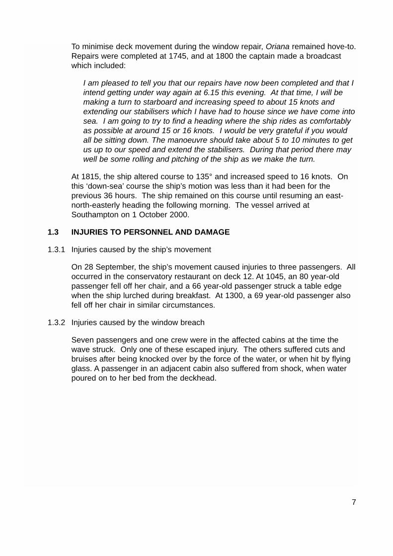
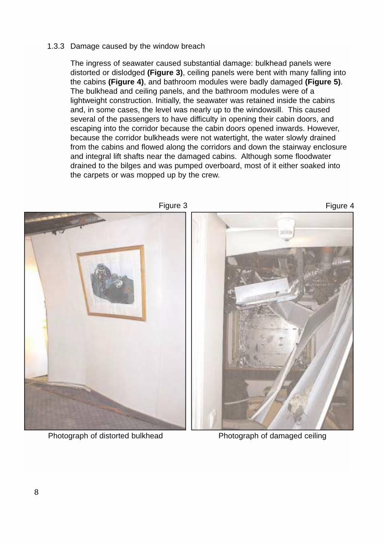
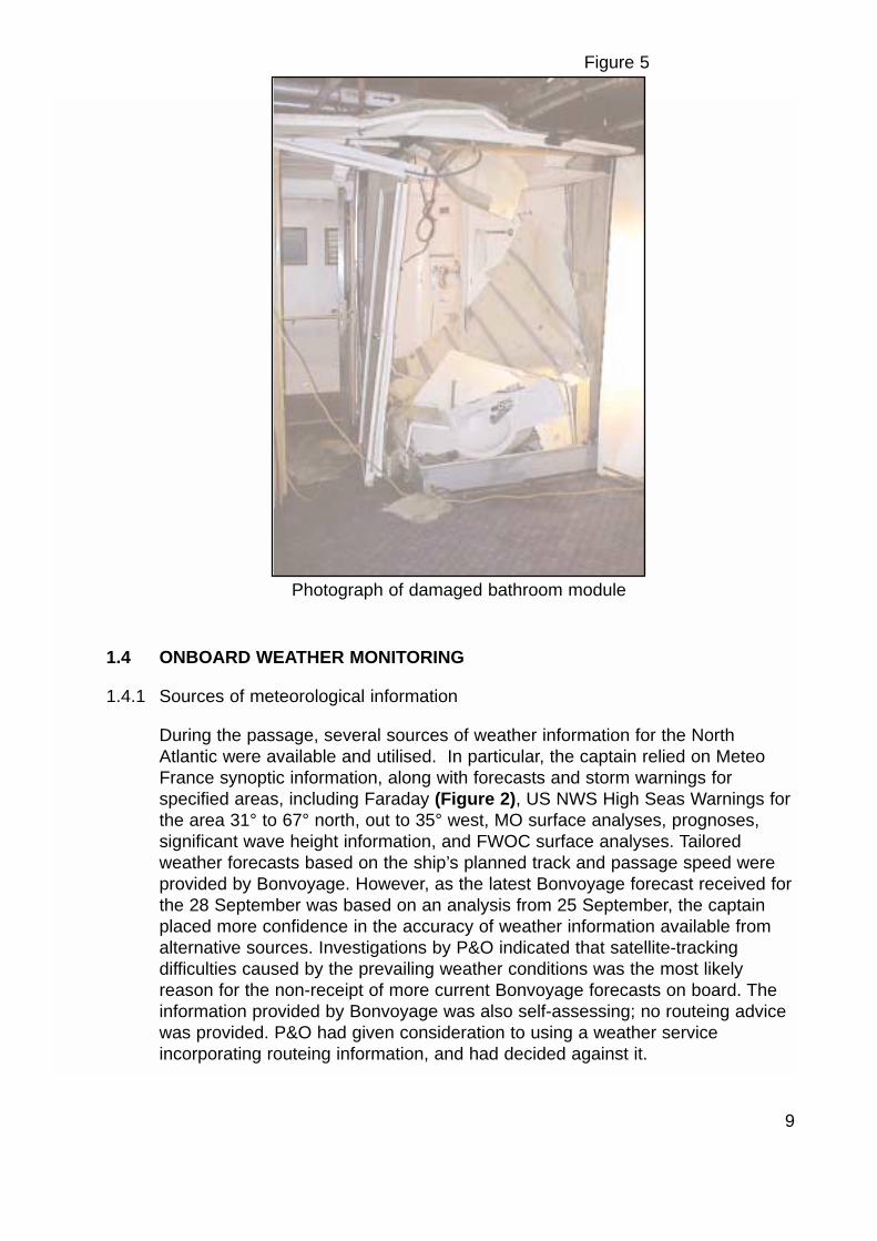
1.3.3 Damage caused by the window breach
The ingress of seawater caused substantial damage: bulkhead panels weredistorted or dislodged (Figure 3), ceiling panels were bent with many falling intothe cabins (Figure 4), and bathroom modules were badly damaged (Figure 5).The bulkhead and ceiling panels, and the bathroom modules were of alightweight construction. Initially, the seawater was retained inside the cabinsand, in some cases, the level was nearly up to the windowsill. This causedseveral of the passengers to have difficulty in opening their cabin doors, andescaping into the corridor because the cabin doors opened inwards. However,because the corridor bulkheads were not watertight, the water slowly drainedfrom the cabins and flowed along the corridors and down the stairway enclosureand integral lift shafts near the damaged cabins. Although some floodwaterdrained to the bilges and was pumped overboard, most of it either soaked intothe carpets or was mopped up by the crew.
Figure 3
Photograph of distorted bulkhead
Figure 4
Photograph of damaged ceiling
1.4 ONBOARD WEATHER MONITORING
1.4.1 Sources of meteorological information
During the passage, several sources of weather information for the NorthAtlantic were available and utilised. In particular, the captain relied on MeteoFrance synoptic information, along with forecasts and storm warnings forspecified areas, including Faraday (Figure 2), US NWS High Seas Warnings forthe area 31° to 67° north, out to 35° west, MO surface analyses, prognoses,significant wave height information, and FWOC surface analyses. Tailoredweather forecasts based on the ship’s planned track and passage speed wereprovided by Bonvoyage. However, as the latest Bonvoyage forecast received forthe 28 September was based on an analysis from 25 September, the captainplaced more confidence in the accuracy of weather information available fromalternative sources. Investigations by P&O indicated that satellite-trackingdifficulties caused by the prevailing weather conditions was the most likelyreason for the non-receipt of more current Bonvoyage forecasts on board. Theinformation provided by Bonvoyage was also self-assessing; no routeing advicewas provided. P&O had given consideration to using a weather serviceincorporating routeing information, and had decided against it.
9
Figure 5
Photograph of damaged bathroom module
1.4.2 Monitoring of the depression
On sailing from New York, the captain was aware of the synoptic situation in theNorth Atlantic, and was paying particular attention to the progress of a lowpressure system, ex-Hurricane Helen, which had been downgraded to adepression. This depression initially moved north-east along the easternseaboard until merging with another weather system to the east ofNewfoundland on 25 September. Although deepening, this depressioncontinued to track north-east towards Iceland and away from the ship’s intendedtrack. On 26 September, however, the following was received from MeteoFrance:
Synopsis, Tuesday 26 at 00 UTC:…Low 983 280 NM south of Cape Farewellmoving Northeast and deepening, expected 971 59N35W by 27/00UTC,then moving east-southeast, expected 974 59N29W by 27/12UTC.
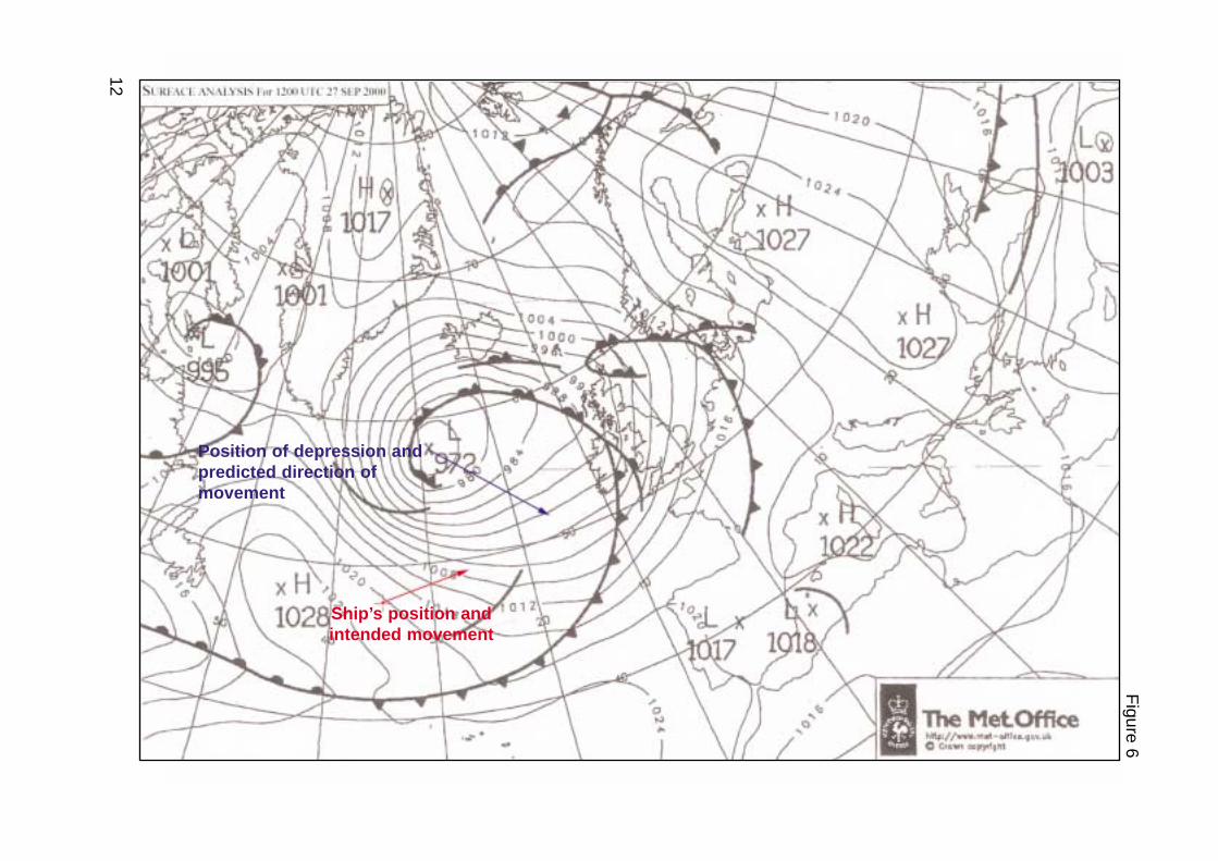
Aware that the depression had, or was about to, change direction to the south-east towards the ship’s planned track, the captain ordered its actual andpredicted positions to be plotted on chart BA 4011, a widely used chart of theNorth Atlantic. The positions plotted were taken from Meteo France forecasts at0900 and 2100 daily. The path of the depression as plotted by Oriana, basedon data supplied by Meteo France, is shown at Figure 2. Additionally, the ship’sposition was plotted on surface analyses and prognoses issued by the MO.Based on this information, the captain assessed that by reducing speed to 19.5knots on the evening of 27 September, the ship would remain sufficiently clearof the depression to avoid the worst of the storm force conditions. The MOsurface analysis for 1200 on 27 and 28 September, with the ship’s positionmarked, is shown at Figures 6 and 7.
1.4.3 Forecast areas
Oriana entered the Faraday forecast area on the afternoon of 27 Septemberand, although leaving the area the following morning, Faraday remained thenearest forecast area for which the ship was receiving detailed forecasts.Relevant extracts of Meteo France area forecasts for Faraday received by theship in English were:
27 September at 0900 (valid until 1200 on 28 September)
Westerly 5 to 7 from south to north, veering soon Northwest, whileincreasing 7 to 9 in east…..Rough or very rough, becoming high, locally veryhigh in east later.
Outlook for next 24 hours: Gradual improvement in FARADAY, ROMEO andCHARCOT. Gale or severe gale in Bay of Biscay with threat of stormwesterly wind and sea becoming high with northwesterly swell 5 or 6 m.
10

11
27 September at 2100 (valid until 0000 on 29 September)
Northwest 4 to 6, locally west or northwest 7 to 9 in east, becoming variable3 to 5 in west soon. Rough or very rough, locally high in east, becoming veryhigh in east.
Outlook for next 24 hours: Gradual improvement in northern areas.
28 September at 0900 (valid until 1200 on 29 September)
In east: Northwest 7 or 8, decreasing soon 4 to 6, then becoming variable 3or 4……Rough or very rough, locally high in east at first..
Outlook for next 24 hours: Gradual improvement in all areas, then threat ofsouthwest gale in FARADAY at the end.
At the time of the wave damage, Oriana was about 45 miles north of Faraday inforecast area Hecate (Figure 2). Forecasts for Hecate were provided in Frenchvia voice radio by RFI and were not monitored onboard. RFI broadcast thefollowing forecasts for Hecate over the same period (translated):
27 September (valid until 1200 on 28 September)
Sector west 7 to 10 from south to north changing direction during the night tonorth-west 8 to 10 moderating at the end of the period 5 to 8 from the westtowards the east. Heavy to very heavy seas lessening at the end of theperiod to the west. Squalls with severe gusts.
28 September (valid until 1200 on 29 September)
North-west 6 to 8 moderating 4 to 6 during the night turning south 4 to 5 tothe west at the end of the period. Very strong to heavy sea lessening to thewest. Showers followed by rain in the west at the end of the period.
1.4.4 Meteorological observations
Entries in the deck log show that from 0100 on 27 September to 1400 on 28September, barometric pressure fell steadily from 1022.7mb to 1008.3mb andthat wind veered and increased from west-north-west force 6 to north-west force10.
1.4.5 Meteorological glossary
Definitions of relevant sea and swell heights, and wind strengths are at the Appendix.
12
Fig
ure
6
Ship’s position andintended movement
Position of depression andpredicted direction ofmovement

13
Fig
ure
7
Ship’s position andintended movement
Position of depression andpredicted direction ofmovement

1.5 STORM WARNINGS
In addition to the information available on the North Atlantic surface analysesand prognoses charts, guidance on distances from the depression’s centre, inwhich storm force winds were expected, was issued by NWS and received bythe ship as follows:
At 2000 on 26 September (valid until 1800 on 27 September)
Winds 40 to 50 kt, seas 19 to 25ft within 300nm W and S quadrants. Alsowinds 25 to 35 kt, seas 10 to 18 ft within 900nm S and 600nm E and 360nmW quadrants and 180nm N. Forecast storm well E of area.
At 1630 on 27 September (valid until 0000 on 29 September)
Winds 35 to 55 kt, sea 20 to 30 ft within 480nm over the SW semi-circle…winds 25 to 35 kt seas 12 to 22 ft elsewhere within 780nm of thesemi-circle.
At 2230 on 27 September (valid until 0600 on 29 September)
Winds 35 to 55 kt seas 20 to 30 ft within 540nm over the SW semi-circle…winds 25 to 35 kt seas 12 to 22 ft elsewhere within 720nm over theSW semi-circle.
1.6 SHIP’S MOTION AND WAVE HEIGHTS
1.6.1 Deck log entries
27 September:
0800 - Rolling gently 1° - 4°. Short/Mod NW swell, rough seas.
1200 - Shipping light spray forward. Pitching in rough seas. Heavy swell.
1600 - Rolling mod in rough seas. Heavy swell.
2000 - Pitching/yawing. Moderately to Long/High WNW swell and rough seas.
0000 - Pitching/rolling moderately, heavily at times to a long, high WNW swelland rough seas.
28 September:
0400 - Rolling and pitching moderately in very rough seas. Heavy swell.
0800 - Pitching and yawing moderately to long/high WNW swell. Very roughseas.
1200 - Shipping light spray forward. Pitching and yawing in long high swell.Very rough.
14

1.6.2 Individual assessments
The captain, who had served on cruise vessels for most of his sea-going career,often in sea and weather conditions broadly similar to those encountered byOriana on this occasion, estimated the sea to be from the port quarter and thewave height to be about 6 to 7m. He also considered the ship motion was notviolent, but that she was moving easily in rough seas.
Just before the accident, the captain had lunch in the officers’ mess on deck 5and then made his way up through the ship to the bridge. During this period hewas able to observe the sea conditions from various levels in the ship, and wassatisfied that waves were not breaking over the promenade deck.
The OOW at the time of the incident estimated the swell height to have beenabout 5m and considered the ship was riding well in a cork-screw motion.Although the occasional larger wave was seen, the height of the waves did notgive cause for concern.
Reports from passengers reflected varying degrees of concern regarding theship’s movement. Many were able to walk around the vessel with ease, whileothers had difficulty in maintaining their balance. Some reports, however,indicated that the ship’s motion was sufficient to cause crockery to slide fromthe tables in the restaurant and for products, such as perfumes and clothes inthe shops, to be dislodged from their racks. Of those passengers interviewed, anumber were worried about the height of the waves, particularly when theyappeared to cover the windows on decks 5 and 6 on the port side.
1.6.3 Video evidence
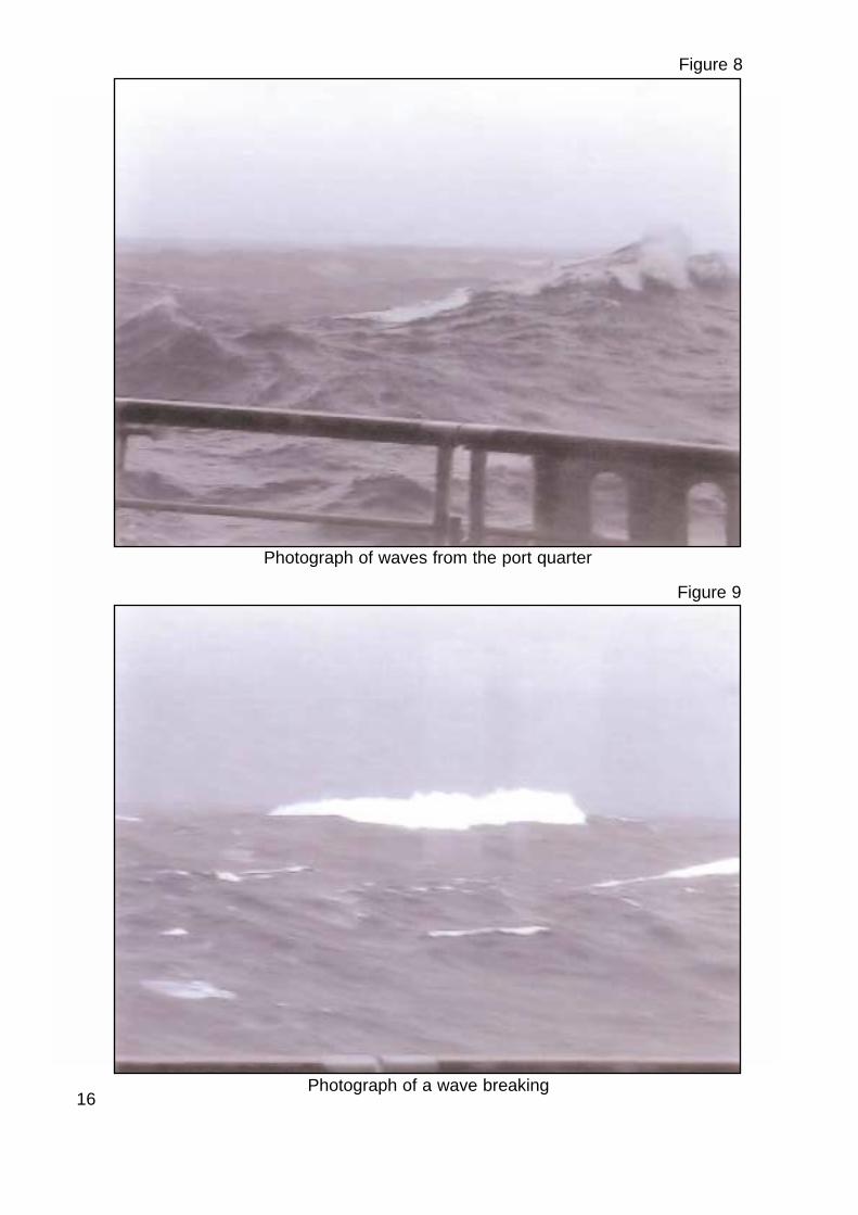
Video recordings taken by passengers on 27 September, and at about middayon 28 September show that the sea conditions worsened during this period.One of the latter recordings, taken from deck 7 on the port side at a height ofabout 13m above the static waterline, from which Figures 8, 9, 10 and 11 weretaken, confirms that the sea and swell were generally from the port quarter.
Figure 9 shows that some of the waves were breaking and Figure 10 shows aplume of spray at deck 7, which probably resulted from a wave impactingagainst the port side. Although it is not possible to determine accurately theheight of the waves from this video, and there is no evidence to suggest thatwaves were breaking over deck 7, Figure 11 possibly indicates that somewaves could have been as high as deck 7.
It is acknowledged, however, that the images shown were taken from differentpositions within the ship, possibly using different focal lengths, and at variousstages of the ship’s movement, and although providing a general guide, theycannot be used as an accurate measure of the conditions prevailing at the time.
15
16
Figure 8
Photograph of waves from the port quarter
Figure 9
Photograph of a wave breaking

17
Figure 10
Photograph of a ploom of spray at deck 7 probably resulting from a waveimpacting on the port side
Figure 11
Photograph of wave of a similar height to deck 7
1.6.4 Voyage Data Recorder
Analysis of the voyage data recorder indicates that the vessel was steering acourse of 071° to make good a course of 077° and that starboard helm,occasionally up to 19°, was required to maintain this course. It also showed that,although the average yaw of the vessel during 28 September was about 3° to 4°either side of the course steered, occasionally it was greater. For example, at1256 the ship yawed from 074° to 062° over several seconds. The impact of thewave at around 1410, however, did not cause a noticeable deflection to theship’s head. No pitch or roll information was available.
1.6.5 Significant wave heights
Significant wave height is defined as the average height of the highest third ofthe waves, and wave height is measured from crest to trough. Diagramsshowing predicted significant wave heights for 0000 and 1200 on 28 September2000, along with the ship’s positions at these times, are at Figures 12 and 13.In a typical storm the expected height of the highest wave is usually 1.8 to 2.0times the size of the significant wave height. There is, however, about a 1%chance of a wave 2.5 times the size of the significant wave height beingencountered.
1.7 THE WINDOWS
1.7.1 Design requirements
Windows were fitted to decks 5 and above in accordance with MCA Regulations.The requirements of BSMA 25 were met and toughened safety glass was used.
BSMA 25, first published in 1973, is the UK national standard for ship’s windowswith glass up to a thickness of 19mm. In most other countries, the nationalstandard for ships’ windows is based on an ISO standard which, in turn, wasbased on BSMA 25.
BSMA 25 required that, for the position and size of the windows fitted on decks5 and 6 of Oriana, the following criteria should be met:
a. The glazing strips should have overlapped all window edges by at least7mm.
b. The glass should have chamfered edges.
c. The glass should be centralised in the frames.
d. Windows on deck 5 should be able to withstand a static pressure head ofwater of 6.57m, and those on deck 6 a static pressure head of 1.5m.
There was also a requirement for windows fitted below lifeboat and liferaftlaunching arrangements to be fire resistant.
18

19
Figure 12
Ship’s position
Diagram showing Significant Wave Heights for 00Z on 28 September 2000
Figure 13
Diagram showing Significant Wave Heights for 12Z on 28 September 2000
Latit
ude
Ship’s position
Latit
ude
Longitude
Longitude
1.7.2 Type approval
Type approval is the process where a product is examined by a competent bodyto determine its fitness for purpose. In this case, type approval for the breachedwindows was undertaken by the MSA, the forerunner to the MCA. A typeapproval certificate was issued in July 1994 after two specimens weresuccessfully fire tested, and the strength was checked against the requirementsof BSMA 25.
The two specimens, fire tested as part of the type approval, had clear heightsand widths of 2000mm and 1000mm; one was fitted with 15mm monolithic glassand the other with 22mm laminated glass.
The certificate of approval stated that mullions and/or transoms should not befitted.
1.7.3 Manufacture
The windows were manufactured by Het Anker in the Netherlands, usingtoughened safety glass supplied by Sacilese in Italy.
The damaged windows on deck 5 were Het Anker Type 507 (Figure 14). Thesewindows had a clear light height and width of 1000mm and 1100mmrespectively. The windows were divided in two by a 50mm wide mullion, with ‘D’shaped glass panes made from 19mm, B-0 fire rated, toughened safety glassfitted on either side. They were designed to withstand a static pressure head ofwater of 8.83m.
The designed height and width of the openings cut in the ship’s side for thewindows was 1064 and 1164mm respectively. A 30mm stainless steel glazingstrip was fitted on each side and this, plus an allowance of 2mm all round forwelding the window frame into the opening in the ship’s side plating, accountedfor the difference between the clear height and width, and the size of theopenings.
The glass was fixed into a recess in the steel window frame. A fire resistantgasket was fitted over the glass where it was in contact with the frame and thestainless steel glazing strip. Figure 14 shows that the gap between the frameand the fire resistant gasket covering the edge of the glass was designed to befilled with chocks made from Promasil 850, which kept the glass central to theframe. The glazing strip, which was located on the inboard side of the window,was 30mm wide by 5mm thick and was screwed into the window frame by M6stainless steel screws spaced 71mm apart. The glass, therefore, was securedin its frame by the force of the screws, acting on the glazing strip. The glazingstrip was 50mm wide in way of the mullion.
20

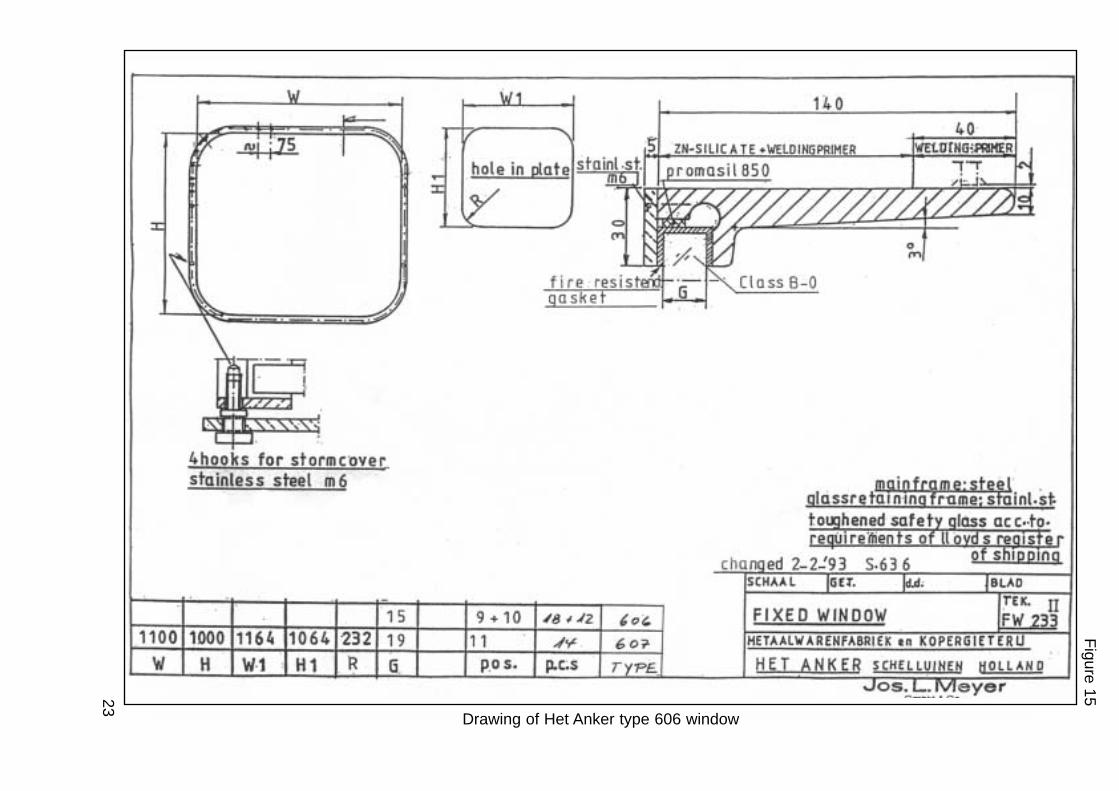
The damaged windows on deck 6 were Het Anker Type 606 (Figure 15). Thesewindows are the same as those fitted on deck 5, except that there was nomullion and the single pane was made of 15mm monolithic glass with fourrounded corners. These were designed to withstand a pressure head of waterof 2.77m.
By scaling the window design drawings (Figures 14 and 15), it is estimated thatthe dimensions of the glass panes fitted in both window types should have beensufficient to produce about a 13mm overlap with the glazing strip.
1.7.4 Quality control
A Lloyd’s Register surveyor visited the Het Anker factory on at least sevenoccasions during 1993 and 1994, specifically to inspect the windows beingmanufactured for Oriana. He also visited the factory on numerous otheroccasions for different reasons, and was able to monitor the standards ofworkmanship and quality control practised. Oriana’s windows were dispatchedin batches, and each window was stamped with the surveyor’s own mark, aftera random sample in each batch had been checked. The windows weresupplied to the shipbuilder with Lloyd’s Register certification based on anapproximate 50% random sample inspection of 385 glass panes for 194windows of various configurations, during manufacture and assembly. Allwindows were examined in the finished state.
Het Anker currently issue welding instructions with all windows dispatched fromits factory (Figure 16), but they were unable to confirm if these or similarinstructions accompanied the windows made for Oriana.
1.7.5 Installation
Het Anker delivered the windows as assembled units. Openings were cut in theship’s side, into which the window assemblies were fitted and the frameswelded to the ship’s side plating. The builders, Meyer Werft, in Papenberg,Germany has no knowledge of any oversize openings having to be cut toaccommodate oversize frames. The thickness of the side plating was 14mm ondeck 5, and 15mm on deck 6. Meyer Werft could not confirm if the weldinginstructions issued by Het Anker (Figure 16),or similar, had been used to securethe windows in Oriana, but a staff member, who had worked on her duringbuilding, recollects a chain intermittent welding sequence being used tominimise distortion. On vessels currently building, Meyer Werft now useultrasonic equipment to check the overlap of the glazing strips over the glasspanes.
Following installation, some glass panes were removed, to allow electric powercables, air lines, and large items to be passed into the ship. The equipmentsupplying all electric power and compressed air, however, was located along herstarboard side during building. It has not been possible to determine whetherany glass panes from windows on the port side, including the damagedwindows, were removed. All windows were hose-tested by the shipbuilder tocheck for leaks. 21

22
Drawing of Het Anker type 507 window
Fig
ure
14
23
Drawing of Het Anker type 606 window
Fig
ure
15

24
Weld
ing in
structio
ns issu
ed b
y Het A
nke
r
Fig
ure
16
25
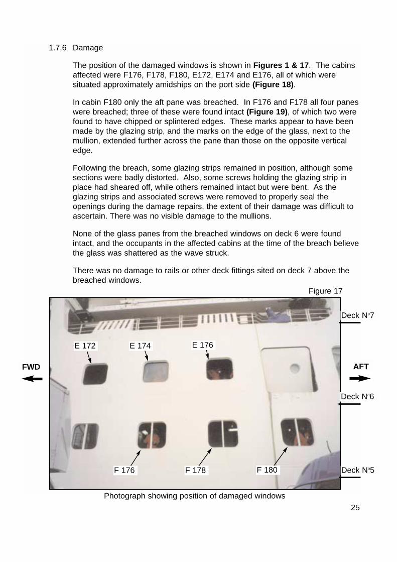
1.7.6 Damage
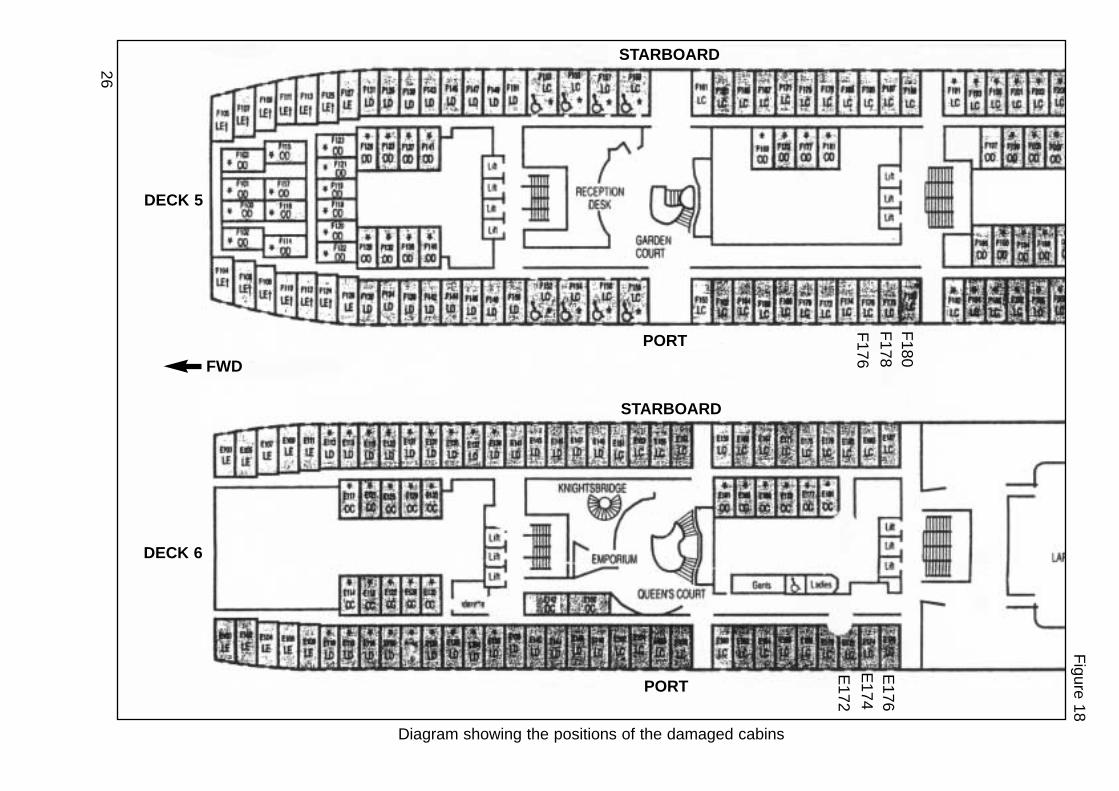
The position of the damaged windows is shown in Figures 1 & 17. The cabinsaffected were F176, F178, F180, E172, E174 and E176, all of which weresituated approximately amidships on the port side (Figure 18).
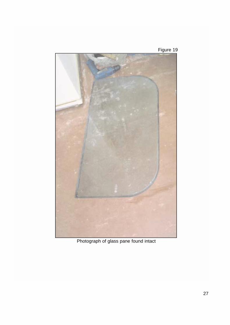
In cabin F180 only the aft pane was breached. In F176 and F178 all four paneswere breached; three of these were found intact (Figure 19), of which two werefound to have chipped or splintered edges. These marks appear to have beenmade by the glazing strip, and the marks on the edge of the glass, next to themullion, extended further across the pane than those on the opposite verticaledge.
Following the breach, some glazing strips remained in position, although somesections were badly distorted. Also, some screws holding the glazing strip inplace had sheared off, while others remained intact but were bent. As theglazing strips and associated screws were removed to properly seal theopenings during the damage repairs, the extent of their damage was difficult toascertain. There was no visible damage to the mullions.
None of the glass panes from the breached windows on deck 6 were foundintact, and the occupants in the affected cabins at the time of the breach believethe glass was shattered as the wave struck.
There was no damage to rails or other deck fittings sited on deck 7 above thebreached windows.
Figure 17
Photograph showing position of damaged windows
AFTFWD
Deck No5
Deck No6
Deck No7
E 172 E 174 E 176
F 180F 178F 176
26
Diagram showing the positions of the damaged cabins
Fig
ure
18
F176
F178
DECK 6
DECK 5
FWD
E172
E174
E176
F180
STARBOARD
STARBOARD
PORT
PORT
27
Figure 19
Photograph of glass pane found intact
28
1.7.7 Damage repairs
Three damage repair parties were formed. The first dealt with the damage ondeck 5, the second dealt with the damage on deck 6, and the third preparedmaterials. The repair parties were organised by the chief technical officer whohad attended an RN damage repair course. It was company policy for P&O tosend all officers of his rank on this course. Another officer involved in therepairs, who had previously served in the RN, had also attended this course.
Initially, the damage repair teams fitted strong-backs which were placed insockets cut into the fairings surrounding the windows, but it was soon evidentthis would not provide sufficient support. However, after discovering that thefairings were attached by screws concealed by small plastic caps, these wereremoved and the fairings taken down to expose the steel structure surroundingthe window frames. Three horizontal strong-backs were then fitted across eachopening, with the ends welded to steel stiffeners on the ship’s side (Figure 20).The strong-backs were either square or angle steel sections obtained from theship’s stores. The windows were then blanked off by either storm covers orplywood sheets. Wooden wedges were then driven into the gap between thestrong-backs and the covers, to secure the covers in place. The materials usedby the repair teams were prepared in the ship’s workshops.
1.8 WINDOW DEFECTS
1.8.1 Examination by P&O
As soon as practically possible after the accident, a detailed dimensional checkwas conducted by P&O on all windows on decks 5 and 6. Several defects wererevealed to varying degrees on a large number of the windows surveyed.Among these defects were:
a. Oversize window frames. The worst case being the damaged window inF178 cabin, which was 16mm wider and 4mm higher than designed. Theremaining damaged windows were larger than designed as follows:
Cabin Width Height
F176 10mm 5mm
F180 10mm 5mm
E172 6mm 6mm
E174 8mm 9mm
E176 4mm 7mm
29
b. On many windows, the glazing strip overlapped the glass by less than 7mm;in some cases the overlap was as low as 2mm. It was also found that thedimensions of nearly all of the glass panes fitted would have allowed anoverlap with the glazing strip of between 7 and 13mm, although many weretowards the lower end.
c. Window-panes not properly centred. This was especially prevalent in thewindows with mullions where the glass was deeply recessed into the mullion,at the expense of the recess on the other vertical edge.
d. Glass panes had a rounded edge profile.
e. Regarding the stainless steel screws used to secure the glazing strips: somewere of differing lengths; some had sheared, some had damaged threads;some threads were covered in mastic while others were not; and many ofthe Phillips heads were damaged.
Figure 20
Photograph of temporary repair to a damaged window
Strong-backs

30
f. Some gaskets looked different to others, and the hardness appeared todiffer. Some windows were fitted with plastic chocks and some were not. Itwas assumed that the chocks were made from Promasil 850.
g. Some stainless steel glazing strips were deformed. Where the gasket wastoo thick for the recess, tightening the screws tended to deform the strip,leading to a gap opening up on the inner edge (Figure 21). Consequently,with a gap at the inner edge of the strip, the glass was not clamped properlyon the frame.
After Oriana’s arrival in Southampton on Sunday 1 October 2000, the MAIB wasunable to carry out its own extensive and detailed survey during the limited timeavailable, because she sailed the following day on her next cruise.
Width of recess
Chock
Window frame
Centreline of screw
Glazing strip
Gap
Glass
Gasket
Diagram showing gap caused by poor fitting gasket
Figure 21

31
1.8.2 Checks and tests conducted by Het Anker
Representatives from Het Anker visited Oriana between 17 and 20 October2000 and surveyed some of the windows previously inspected by P&O. As aresult of this survey, Het Anker contend that the dimensions of the glass panesseen were generally larger than measured by P&O.
Het Anker also conducted a number of destructive tests following the accident,from which it formed the opinion that the windows delivered to Meyer Werft metthe as-designed strength requirements, and that the wave pressure causing thedamage, exceeded this strength.
1.9 STORM COVERS
1.9.1 Requirements
The requirements for storm covers or shutters are contained in the MCA’sInstructions for the Guidance of Surveyors on Passenger Ship Construction.Oriana was required to carry enough covers for 50% of the windows on deck 5,and for 25% of the windows on deck 6. The covers were required to be madefrom 3.5mm steel or equivalent, and be “provided with means of securing themto the frame sufficient to withstand the pressures likely to be experienced inservice”.
1.9.2 Securing arrangements and construction
“T” shaped lugs were screwed into the frames of both types of window on whichstorm covers could be slotted, to provide a barrier on the inside of the glass(Figures 22 and 23). The storm covers were made from 4mm thick aluminiumplate, which was stiffened by two aluminium flat bars, rather than from 5mmunstiffened aluminium plate as originally designed. The shipbuilders assured theMCA at survey that these 5mm aluminium covers were of equivalent strength to3.5mm steel plate. There is no evidence available to indicate that the MCA didnot accept this assurance.
1.9.3 Damage
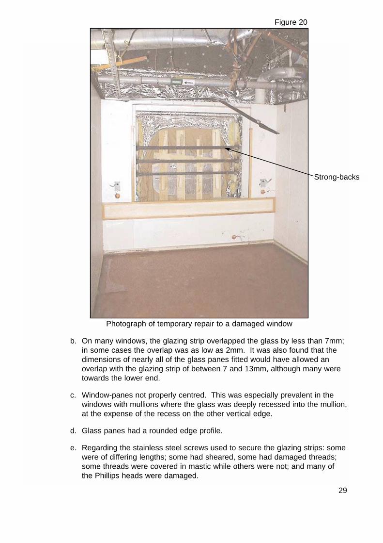
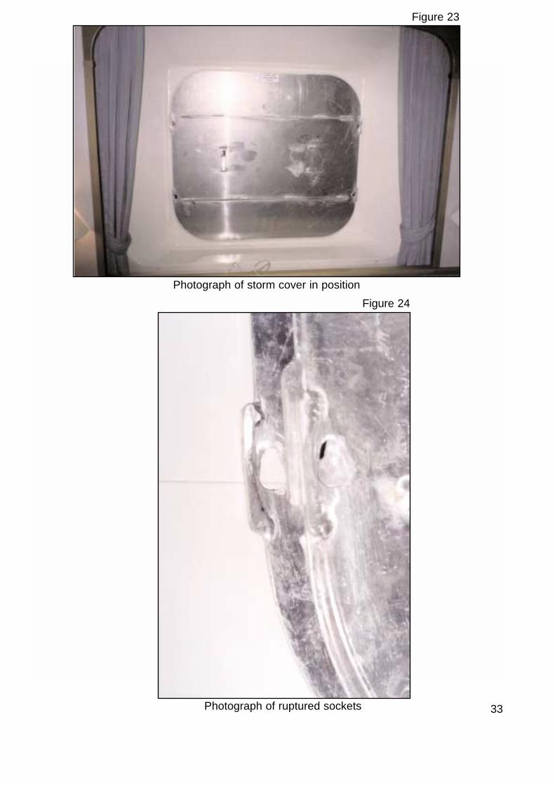
When the windows fitted with storm covers on deck 5 were breached, the stormcovers were forced off their mountings by the pressure of the water. Thesockets cut in the sides of the storm covers were ruptured as they were pushedoff the lugs (Figure 24). The storm covers were also bowed.

32
Lug
Window frame
Storm cover
Socket fitted over lug
Lug secured in socket
Front elevation Side elevation
Diagram of the securing arrangement for storm covers
Figure 22
33
Figure 23
Photograph of storm cover in position
Figure 24
Photograph of ruptured sockets
1.10 VESSEL CONDITION
At the time of the accident, the centre of the damaged windows on deck 5 wasabout 7.3m above the static waterline, while the centre of the damaged windowson deck 6 was about 10.1m above the static waterline. The draught of thevessel at the time was 8.343m aft and 8.015m forward. The condition at thisdraught was checked against the stability book and it was confirmed that Orianawas not overloaded, ie the windows were not closer to the waterline than theyshould have been.
1.11 ACTION TAKEN REGARDING YACHT IN DISTRESS
At 0720, on 28 September, a telex was received from MRCC Falmouth, stating adistress beacon signal had been detected on 406MHz in position 49° 56N, 019°23W, and requesting all vessels in the area to inform the MRCC. As Oriana wasabout 240 miles away, she responded by passing her position, course, andspeed, along with the current weather conditions and ETA.
At 1000, course was adjusted to 077° to proceed directly to the position of thedistress beacon but, at 1239, MRCC Falmouth informed Oriana that AtlanticCompanion was proceeding to assist the vessel in distress, and authorised herto stand down from the emergency.
At 1407, the OOW received a radio call from MRCC Falmouth advising that,although Atlantic Companion had located a de-masted Canadian yacht, she washaving difficulty in evacuating its crew. MRCC Falmouth asked whether Orianawould be able to assist if required when she arrived in the area that evening.Immediately the OOW requested the captain to come to the bridge to beappraised of the situation. The captain arrived on the bridge at about 1410, justas the alarm in cabin F178 sounded.
1.12 ACTION TAKEN FOLLOWING THE ACCIDENT
1.12.1 Temporary Repair
a. Windows
After the accident, P&O repositioned all window-panes on decks 5 and 6which were not properly centred, and fitted steel retaining plates to thecorners of all windows on decks 5 and 6 (Figures 25 and 26). These plateswere fitted on top of the existing glazing strip, with the intention of increasingthe overlap and the grip of the frame on the glass. No retaining plates werefitted at the junctions between the mullion and the main part of the frame.This work was proposed by Lloyd’s Register as a temporary measure, andcarried out by P&O to standards approved by Lloyd’s Register.
34

35 Diagram of retaining plate
Fig
ure
25
Proposed cornerdoubler
Rubber seal
View A-A
A- A
60mm
30mm
8mm5mm
30
mm
60m
m
12
mm
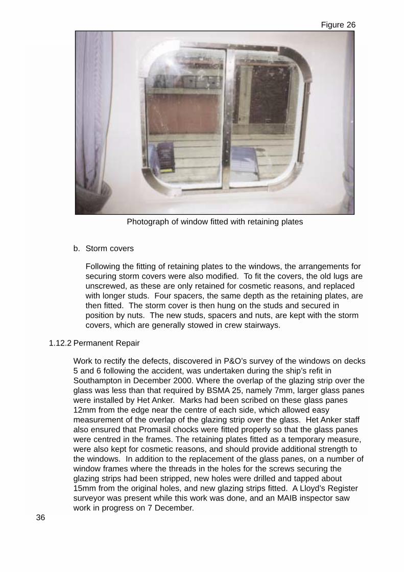
b. Storm covers
Following the fitting of retaining plates to the windows, the arrangements forsecuring storm covers were also modified. To fit the covers, the old lugs areunscrewed, as these are only retained for cosmetic reasons, and replacedwith longer studs. Four spacers, the same depth as the retaining plates, arethen fitted. The storm cover is then hung on the studs and secured inposition by nuts. The new studs, spacers and nuts, are kept with the stormcovers, which are generally stowed in crew stairways.
1.12.2 Permanent Repair
Work to rectify the defects, discovered in P&O’s survey of the windows on decks5 and 6 following the accident, was undertaken during the ship’s refit inSouthampton in December 2000. Where the overlap of the glazing strip over theglass was less than that required by BSMA 25, namely 7mm, larger glass paneswere installed by Het Anker. Marks had been scribed on these glass panes12mm from the edge near the centre of each side, which allowed easymeasurement of the overlap of the glazing strip over the glass. Het Anker staffalso ensured that Promasil chocks were fitted properly so that the glass paneswere centred in the frames. The retaining plates fitted as a temporary measure,were also kept for cosmetic reasons, and should provide additional strength tothe windows. In addition to the replacement of the glass panes, on a number ofwindow frames where the threads in the holes for the screws securing theglazing strips had been stripped, new holes were drilled and tapped about15mm from the original holes, and new glazing strips fitted. A Lloyd’s Registersurveyor was present while this work was done, and an MAIB inspector sawwork in progress on 7 December.
36
Figure 26
Photograph of window fitted with retaining plates
1.12.3 P&O
Since the accident, P&O has:
a. Checked all windows, similar to those breached on Oriana, on Oriana andother ships in its fleet.
b. Issued an instruction that storm covers are not to be fitted as a precaution inheavy weather in spaces occupied by passengers or crew.
c. Issued an amendment to its regulations instructing captains to implementheavy weather precautions, particularly with regard to public areas andelderly passengers, at an early stage.
d. Issued a further amendment to its regulations instructing captain’s to makearrangements to monitor the sea state from positions other than the bridge,particularly in marginal weather and sea conditions.
1.12.4 Meyer Werft
By November 2000, the shipbuilder, had taken the following action:
a. Issued instructions obliging its sub-contractors not to make any changes tostructural elements of ships, unless specifically advised to do so.
b. Intensified the vetting of sub-supplier’s work to ensure appropriateregulations and working standards are adhered to.
c. Reminded classification societies operating in their shipyard of theirresponsibilities.
d. Reminded its workforce that if class-related items are changed, they must bere-inspected by a class surveyor, and records of such incidents must bekept.
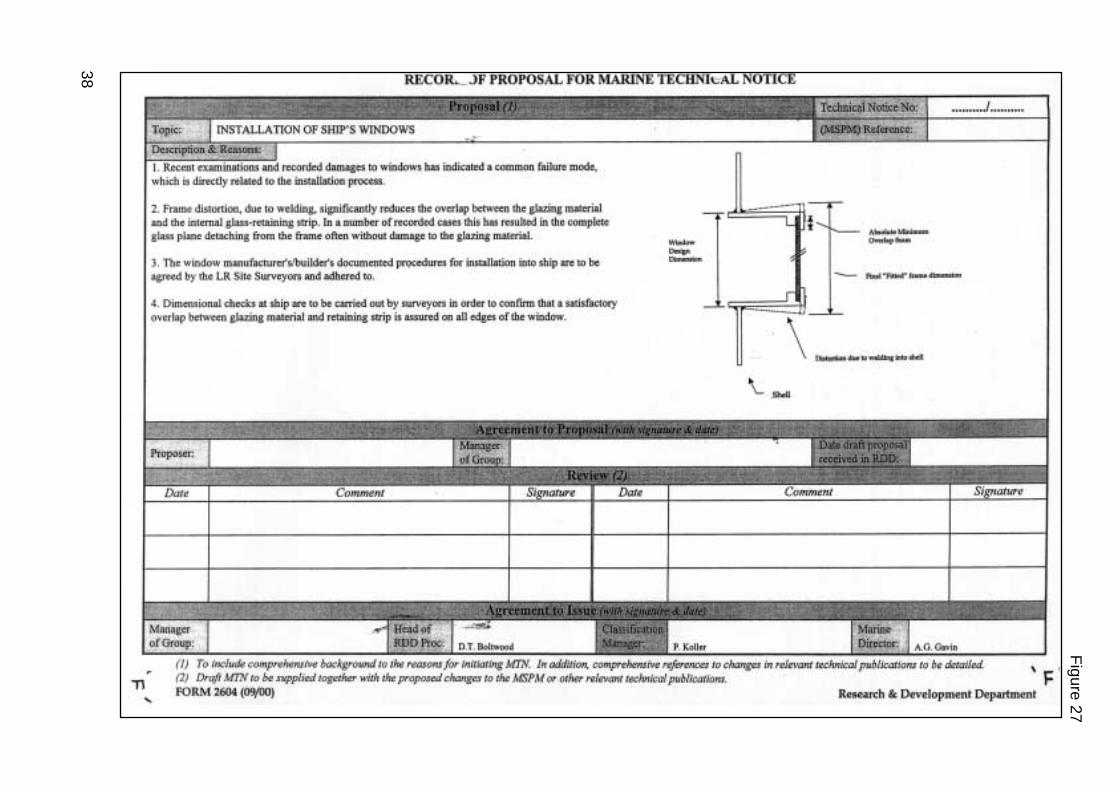
1.12.5 Lloyd’s Register
Lloyd’s Register has issued a Marine Division Technical Notice to all its officesto provide guidance on the potential problem of window frames becomingoversize because of distortion caused when welded to the ship’s side, and thedimensional checks that should be carried out following installation (Figure 27).
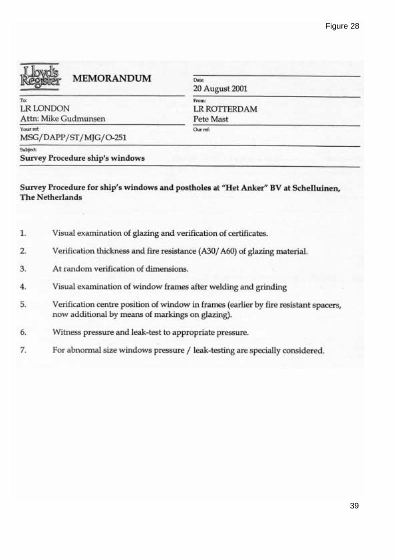
In August 2001, the Rotterdam office of Lloyd’s Register introduced proceduresto ensure that its surveyors at the Het Anker factory are able to monitor productquality (Figure 28).
1.12.6 Het Anker
Het Anker has reviewed key components of its windows, such as the glazingstrips, which they consider to be the weak points of the window design.
37
38
Fig
ure
27
39
Figure 28
SECTION 2 - ANALYSIS
2.1 WINDOW DESIGN
The design of the windows fitted on Oriana is not identical to the drawingsissued with the type approval. However, as the drawings are generically thesame, it is considered the window design met the requirements of theregulations.
The type approval certificate did not allow the use of mullions. Mullions,however, could be accepted by the MCA on a case by case basis, provided itcould be shown they were of adequate strength. Although there is no evidenceof any application for approval of mullions in Oriana’s case, the absence ofdistortion to the mullions following the accident, indicates that they were ofsufficient strength.
To provide maximum strength, glazing strips should ideally be fitted on theoutside. This allows the pressure load on a window, caused by a wave, to betaken on the frame rather than the glazing strip. As in Oriana, however, whereaccess to the windows from the outside for maintenance is extremely difficult,the glazing strips are usually fitted on the inside. The MAIB is not aware of anypassenger cruise ships where this is not the case. BSMA 25 does not specifywhich side the glazing strip should be fitted.
BSMA 25 provides the design standard for frames and retaining systems up toglass thickness of 19mm and up to length and breadth of 1100mm x 800mmrespectively. Although the windows on deck 6 were 1100mm x 1000mm, theglass used was 15mm thick, which is well below the maximum of 19mm. It isconsidered, therefore, that the application of BSMA 25 in this instance wasappropriate. The windows on deck 5 were fitted with 19mm glass, and becausemullions were fitted, they were well within the size range shown in BSMA 25.The strength of the glass fitted to the damaged windows on decks 5 and 6 wassufficient to resist the pressure required by BSMA 25.
In summary, the design of the windows on decks 5 and 6 was close enough tothe windows approved by the MSA to be acceptable.
2.2 WINDOW DEFECTS
2.2.1 General
A consequence of oversize frames and window-panes not being properlycentred was that the glazing strips did not overlap the glass by at least 7mm, asrequired by BSMA 25. This reduced the strength of the windows, which wasfurther reduced by glazing strips not clamping the glass properly becausegaskets either were too thick, or of incorrect size, and damaged screws being
40

used. As these defects were widespread on the windows throughout decks 5and 6, it is highly probable that similar defects were present on those damaged.This is supported by the marks found on two of the panes which remainedintact.
Oversize frames are only problematic if insufficient overlap of the glass edgeswith the glazing strip results. Had the glass been manufactured to provide thedesigned overlap of about 13mm, the detrimental effect on the overlap causedby the oversize frames would have been less significant. Because many of theglass panes fitted had been manufactured to provide the minimum overlaprequired by BSMA 25, oversize frames inevitably resulted in an overlap belowthat required by the standard in many of the windows.
Each of the latent defects discovered by P&O immediately following theaccident might not have been particularly detrimental to the strength of thewindows on its own, but it is considered their cumulative effect made themsignificantly weaker than designed. It is therefore possible that a number ofwindows were weaker than required by BSMA 25.
The difference in the appearance and hardness of the gaskets was probablybecause gaskets fitted below lifeboat and liferaft-launching arrangements had tobe fire resistant, whereas those fitted elsewhere did not.
2.2.2 Defects originating during manufacture
Some window deficiencies could have been the result of sub-standardmanufacture and assembly at the Het Anker factory. If this was the case, theywere not detected either by Het Anker’s quality control system, or by the Lloyd’sRegister surveyor during his visits to the factory in 1993 and 1994. None of thelatent defects, later discovered by P&O, were identified during this period. Thisimplies that either the defects were not present, or that the quality assuranceand inspection procedures were inadequate.
All of the glass panes fitted should have had chamfered edges. The illustrationof the dimensions of arris for the edges of the glass panes in BSMA 25 clearlyshows the edges to be chamfered. Oriana’s windows, however, were deliveredwith rounded edges, which it is considered would have made them marginallymore prone to being forced from the frames. It is considered that this defectshould have been detected by both Het Anker and Lloyd’s Register.
Although there are differences between P&O’s and Het Anker’s measurementsof the glass panes on decks 5 and 6, the fact that many of the glass panes werenot large enough to allow the as-designed overlap of 13mm (by scaling thedrawing) with the glazing strip remains. However, as the glass panes facilitatedthe minimum overlap of 7mm, the windows still met with the standard requiredby BSMA 25 in this respect, provided the glass was centralised in the frames.
41
2.2.3 Defects during and after installation
a. Oversize frames.
The windows were delivered to the shipyard as assembled units, and werewelded into position while the ship was on a level building berth. If theframes were oversize when they were delivered to the shipyard, oversizeopenings would have had to be cut to accommodate them. The fact that theshipyard has no knowledge of oversize openings being made, supports thepossibility that the oversize frames resulted from the welding process,despite the fact chain welding techniques might have been used.
It is also possible that as most cruise ships tend to hog when they are afloat,the resultant bending of the hull girder following launch, could have led to thestretching of some window frames. This would have been at a maximumnear amidships where the bending moment is greatest, and where thewindow 16mm oversize in cabin F178 was located. However, any distortioncaused in this way would probably have been minimal.
b. Defects
The removal, and subsequent refitting, of the glass panes in the shipyardcould have been the source of several of the window defects, particularly ifnon-specialists had undertaken the work. When replacing the glass panes,the importance of using chocks to centre the glass might have beenoverlooked and, if new gaskets had been fitted which were thicker than theoriginals, screws might have been over-tightened, causing them to sheer orcausing damage to the screw heads. It is also possible that some originalscrews might have been lost and been replaced with screws of incorrectlength. The requirement to hose-test the windows would not have identifiedsuch defects because this is only a test for leakage; no significant loading isplaced on the windows during hose testing.
2.2.4 Origin of defects
During visits by MAIB inspectors to the Het Anker factory on 14 December 2001,and the Meyer Werft shipyard on 25 January 2002, the standard of workmanshipand quality control at both sites appeared to be high. The origin of the defectsdetailed in paragraph 1.7 could not be identified, but must have lay with thewindow manufacturer, the shipbuilder, or both. The defects had therefore beenpresent prior to Oriana’s delivery to P&O, but had not been detected.
42

2.3 FAILURE MECHANISM
The MAIB believes the windows breached because of one, or a combination of,the following:
a. The glass pane was unevenly supported by its frame. Wave impact andpressure head pushed the window-pane out except where it was properlysupported. The resultant bending moment close to the supported edgecaused the glass to shatter. This failure mode was identifiable, becauseglass fragments were found under the glazing strips on one side of somewindows, and would have appeared as an instantaneous failure aswitnessed by some of the occupants of the affected cabins.
b. The glass pane was unevenly supported by its frame, as above. However,the glass did not break but was forced out of its frame and into the cabinwhere it either shattered when it hit something in the cabin, or it remainedintact.
To have breached the windows on deck 6 and damaged the cabin interiors tothe extent illustrated in Figures 3, 4 and 5, the wave must have been at least10m high and must have impacted with force. As waves possibly as high as13m were observed shortly before the window breach (Figure 11), it is feasiblethat Oriana was struck by a wave with a force exceeding the designed windowstrengths. This might have been particularly so if Oriana was struck by abreaking wave, which exerts a greater force than a static wave of the samelength.
It has not been possible, however, to determine if the failure of the windows wascaused by a wave, the force and static pressure head of which, was greater orless than those required by BSMA 25. The MAIB has no evidence that otherwindows complying with this standard have failed in service. This, along with thefact that the impact was neither heard nor felt by the crew on the bridge, norcaused a deflection to the ship’s head, lends weight to the argument that thewave might not have exceeded the requirements of BSMA 25.
Regardless of whether the wave that struck did, or did not, exceed the statutorystrength requirements, the MAIB considers that, had the windows beenmanufactured and installed as designed, they would have been more likely havebeen able to withstand the force exerted by the wave.
2.4 STORM AVOIDANCE
Ships are not expected to alter course to try to avoid every depression theyencounter. The intensity of a depression, wind strength, sea and swell heightand direction, the size and seaworthiness of the vessel, and the purpose of thevoyage, are among many factors to be considered before taking such action.
43

In this instance, the captain was made aware of the conditions associated withthe Atlantic low pressure system in question, via warnings issued from 26 to 28September by Meteo France and the National Weather Service. In response tothe potential discomfort and disruption posed by this weather system, thecaptain plotted its movement relative to the ship’s position and intended track.
Analysis of Figure 2 indicates the approximate distances between the centre ofthe depression (Meteo France and Bracknell positions) and the ship on 27 to 28September were as follows:
Date/Time Distance
270001 950 miles
271200 800 miles
280001 500 miles
281200 420 miles
281410 400 miles
It is evident from the above distances that, from the morning of 28 September,Oriana was on the edge of the south-west sector in which the force 10 windswere forecast by NWS. This is supported by the distances between the isobarsin Figure 7, which indicate a wind strength of about 50 knots in the vicinity ofthe ship’s positions, at 1200 on 28 September, and the recorded barometricpressure and wind speed and direction.
Based on the information and forecasts available on 27 September, the captainassessed that, if the ship continued on her planned route at a reduced speed of19.5 knots, she would remain clear of the worst of the storm conditions. Figures7 and 13 support his assessment, showing conditions to have been marginallymore severe towards the centre of the depression. Nevertheless, although theship remained on the south-western edge of the depression, she continued toclose sufficiently to encounter storm force winds and very high seas.
Weather systems are dynamic phenomena, and even though the movement of adepression can be closely monitored, the application of weather forecastinformation by a moving platform using onboard resources can be problematic.Weather charts are usually very small scale, and lack an accurate means ofdetermining direction. Consequently, the plotting of positions and tracks tends tobe approximate. The forecast areas also tend to be large. Although Faraday isnot dissimilar in area to that of the UK, and weather will invariably differ indifferent parts of the area, forecasts tend to give only generalised information. Itis unfortunate that satellite-tracking difficulties prevented Oriana receiving up-to-date tailored weather forecasts from Bonvoyage, which would have been of
44

assistance. Despite this, however, the ship received ample weather informationfrom a variety of sources. As the forecasts for areas Faraday and Hecate weresimilar during 27 and 28 September, the lack of weather forecasts for areaHecate is not considered to have been significant.
2.5 SAFETY CONSIDERATIONS
In deciding to continue on a course of 077°, the captain had several factors toconsider: the conditions experienced, the conditions expected, the safety of theship, the safety of personnel, the ETA in Southampton, the yacht in distress, andthe alternative options available.
On encountering heavy weather, although wind strength, sea state and waveheight are key indicators, ship motion is usually the simplest method to gaugethe risks posed by the conditions. When heading directly into large seas atspeed, the increased stresses on the hull caused by slamming into the wavesinvariably gives cause for concern and may force a change in course and/orspeed. In this case, the captain’s actions were based on the fact that Orianawas experiencing a quarter sea and was having no difficulty in coping with theresulting cork-screw motion. This movement might have been uncomfortable ordisconcerting to some passengers, and would have increased the risk of injuryto personnel if adequate precautions were not taken. However, it should notnormally have endangered the structural integrity of the ship. Furthermore, theweather forecasts received for area Faraday indicated a gradual improvement inthe conditions.
From Oriana’s bridge, an observer looks down to the sea from a height of about27m. From this perspective, the vertical dimension of a wave is condensed, andthe sea may appear flatter than it actually is. Also, the motion experienced by aship the size of Oriana in high seas is much less than that experienced bysmaller vessels, particularly when the ship’s roll is dampened by the use ofstabilisers, and can lead to an under-estimation of the sea state or make thepresence of occasional larger waves less obvious. The captain, however, hadobserved the sea conditions from various levels, ranging from deck 5 to thebridge. Such observations would have reduced the possibility of an under-estimation of the sea conditions, had they been viewed from the bridge alone.
ETAs are important to passenger ships. If they are not met, berths need to bere-booked, following cruises rescheduled, and passengers’ onward travelreorganised, all of which involve expense and disruption. It follows, therefore,that the captain would have felt some responsibility to arrive in Southampton asplanned. Notwithstanding this, as the captain was prepared to delay the ship’sETA by reducing speed on the evening of 27 September, there is no evidence tosuggest that the ship’s timely arrival in Southampton was a greaterconsideration than her safety. The captain, however, would not have wanted tobe later than absolutely necessary. Although the option of turning to a more
45

‘down sea’ course would have reduced ship movement and increasedpassenger comfort, as it did following the accident, it was thought to beunnecessary and would have meant steering away from the yacht in distress. Itwould also have considerably delayed the ship’s arrival in Southampton. Afurther reduction in speed was also an option but, had this been considered tohave been required by the conditions, it is likely that the stabilisers would havebeen less effective and the frequency of the waves passing the vessel wouldhave increased, making ship motion more violent. Furthermore, as the wavecausing the damage probably came from the port quarter, a reduction in speedwould not have decreased the relative velocity between the wave and the ship atthe time of impact. It is considered, therefore, that a speed of 19.5 knots wasappropriate in the conditions, and did not contribute to the damage sustained.
2.6 RISK TO PERSONNEL
The precautions of restricting access to exposed areas, advising passengers totake care when moving about the ship, closing dead-lights, and fitting stormcovers over appropriate windows, were aimed at minimising the risk of injury topersonnel. Such actions are similar to precautions taken by many ships inheavy weather. The advice to elderly passengers to avoid the conservatory ondeck 12, however, was made in response to accidents to passengers caused bythe movement of the ship. When a ship rolls, the movement of the deck is morepronounced on the higher decks. Such movement might not be considered tobe uncomfortable to a mariner, but probably would be to elderly passengers notused to ship movement. It is therefore possible that the risk of injury to elderlypersons in this area could have been foreseen, and the advice given sooner.Also, it would have been prudent to have ensured that the stock in the shopswas secured before deck movement became sufficient to dislodge these items,not after.
2.7 STORM COVERS
The original design of the storm covers showed the material used to be 5mmunstiffened aluminium plate, which was accepted by the MCA. It is apparent,however, that the material used was 4mm stiffened aluminium plate. Althoughno written evidence is available to show that this revision was accepted by theMCA, the MAIB considers that the strength of the two constructions would havebeen similar.
Ideally, storm covers should be fitted on the outside of windows, to protect theglass. A wave impacting on a cover secured in this manner will tend to force thecover on to the frame, making the strength requirements of the securingarrangements less critical. However, where access to the outside of windows isnot practical, as was the case for the breached windows in Oriana and windowsfitted in all known passenger cruise ships, storm cover mountings must belocated on the inside of the window.
46
Storm covers can be fitted in anticipation of heavy weather, as the numbers thatare required to be carried possibly suggest, or they can be used to close offopenings after a window has been breached. Which of these applications isintended by the regulations is unclear, and may possibly change depending onwhether storm covers are fitted internally or externally. If storm covers areintended to be fitted before heavy weather, they should be at least as strong,but preferably stronger, than the window. If they are not, a wave breaking awindow would also probably dislodge the storm cover. Alternatively, if stormcovers are intended to blank off openings left by breached windows, thestrength of the covers and associated securing arrangements is not so critical,providing the relevant interior spaces remain unoccupied.
In Oriana’s case, the storm covers were fitted to some windows on deck 5 asadditional protection against the heavy weather, but failed at the same time asthe windows. This was because of inadequate securing arrangements. Thedislodged storm covers could have caused severe injuries to the occupants ofthe affected cabins on deck 5, more so than the toughened safety glass fromthe windows, which is designed to shatter into small pieces.
The MAIB considers that the intended use of storm covers requires clarificationand, if storm covers are to be fitted on the inside of windows as a precautionagainst heavy weather, more detailed guidance on strength requirements needsto be issued. It is understood the MCA is considering a proposal by Lloyd’sRegister to waive the requirement for storm covers where double-glazedwindows are fitted and both the inner and outer windows meet the requirementsof BSMA 25.
The MAIB is not satisfied that the new securing arrangements in Oriana willmake the storm covers stronger than the windows they are designed to cover.Therefore, these covers are considered to be suitable for use following awindow breach when the spaces they are protecting can be left unoccupied;they are not suitable to act as a precaution in heavy weather.
2.8 DAMAGE REPAIRS
It is considered that the crew responded very effectively to the breachedwindows. The formation of three teams to deal with the emergency, enabled theopenings to be closed quickly. The attendance at the RN damage repair courseby two of the officers involved probably helped significantly in this respect. It isconsidered that, through frequent and comprehensive broadcasts, the captainkept the passengers fully informed throughout the incident.
47
2.9 REMEDIAL ACTION
The action proposed by Lloyd’s Register and undertaken by P&O to thestandard required by Lloyd’s Register to centre the glass panes, and fit retainingplates on all the windows on decks 5(F) and 6(E), was appropriate as atemporary measure. The work undertaken during the ship’s refit in December2000 is considered to be a satisfactory permanent solution.
2.10 ACTIONS TAKEN FOLLOWING THE ACCIDENT
The MAIB considers the actions taken by P&O, Lloyd’s Register, Meyer Werft,and Het Anker following the accident were necessary, and should help preventsimilar occurrences in the future.
2.11 TRENDS IN SHIP’S WINDOW DESIGN
During this investigation, it was apparent that windows much larger than thosefitted in Oriana, were being manufactured and installed on a number of cruiseships under construction. While it is considered that the size range detailed inBSMA 25 covers the windows fitted in Oriana, it does not cover these largerwindows, some of which contain 25mm glass. The MAIB assumes that, as thesewindows are outwith the standard, window manufacturers must be extrapolatingdata contained in BSMA 25 or equivalent standards, or working to their ownstandard. This is not satisfactory, and the MAIB considers that the standard forwindows requires revision. Such revision should also take into account changesin technology and window design, and could also incorporate the requirementsfor storm covers, addressing the problems with the current requirements alreadymentioned in this report.
48

SECTION 3 - CAUSE
3.1 IMMEDIATE CAUSE:
Sea water ingress was caused by a large wave hitting and breaching threewindows fitted with storm covers on deck 5(F), and 3 windows on deck 6(E).
3.2 CONTRIBUTING FACTORS:
1. The cumulative effect of various defects made many of the windows significantlyweaker than designed, and a number possibly weaker than required by BSMA25.[2.2]
2. Many windows did not meet the requirement of BSMA 25 in respect of theoverlap of the glass pane and the glazing strips being at least 7mm. This wasdue to a combination of oversize frames, glass panes not being properlycentred, and the dimensions of the glass panes supplied.[2.2.2]
3. None of the latent defects, which might have been caused during manufacture,were found by a Lloyd’s Register surveyor during inspections of Oriana’swindows at the Het Anker factory during 1993 and 1994.[ 2.2.2]
4. Oversize frames were probably the result of distortion caused when thewindows were welded into the ship’s side.[2.2.3]
5. Some of the window defects might have been caused by incorrect refitting ofglass panes in the shipyard, following their removal.[2.2.3]
6. The origin of the latent window defects discovered by P&O as soon aspractically possible following the accident must have lay with the windowmanufacturer, the shipbuilder, or both.[2.2.4]
7. Although speed was reduced to avoid encountering the conditions at the centreof the depression, the ship still experienced storm force winds and very highseas.[2.4]
8. The wave causing the damage was probably larger than 10m high and possiblyimpacted with a force greater than the designed strength of the windows.[2.3]
9. Had the windows been manufactured and installed as designed, they wouldhave been more likely to have been able to withstand the pressure exerted bythe wave.[2.3]
10. The storm cover mounting arrangements were of inadequate strength.[2.7]
11. There is little guidance on the intended use and strength of storm covers. [2.7]
49
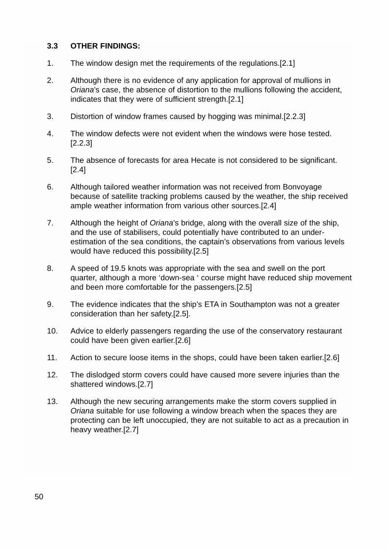
3.3 OTHER FINDINGS:
1. The window design met the requirements of the regulations.[2.1]
2. Although there is no evidence of any application for approval of mullions inOriana’s case, the absence of distortion to the mullions following the accident,indicates that they were of sufficient strength.[2.1]
3. Distortion of window frames caused by hogging was minimal.[2.2.3]
4. The window defects were not evident when the windows were hose tested.[2.2.3]
5. The absence of forecasts for area Hecate is not considered to be significant.[2.4]
6. Although tailored weather information was not received from Bonvoyagebecause of satellite tracking problems caused by the weather, the ship receivedample weather information from various other sources.[2.4]
7. Although the height of Oriana’s bridge, along with the overall size of the ship,and the use of stabilisers, could potentially have contributed to an under-estimation of the sea conditions, the captain’s observations from various levelswould have reduced this possibility.[2.5]
8. A speed of 19.5 knots was appropriate with the sea and swell on the portquarter, although a more ‘down-sea ‘ course might have reduced ship movementand been more comfortable for the passengers.[2.5]
9. The evidence indicates that the ship’s ETA in Southampton was not a greaterconsideration than her safety.[2.5].
10. Advice to elderly passengers regarding the use of the conservatory restaurantcould have been given earlier.[2.6]
11. Action to secure loose items in the shops, could have been taken earlier.[2.6]
12. The dislodged storm covers could have caused more severe injuries than theshattered windows.[2.7]
13. Although the new securing arrangements make the storm covers supplied inOriana suitable for use following a window breach when the spaces they areprotecting can be left unoccupied, they are not suitable to act as a precaution inheavy weather.[2.7]
50
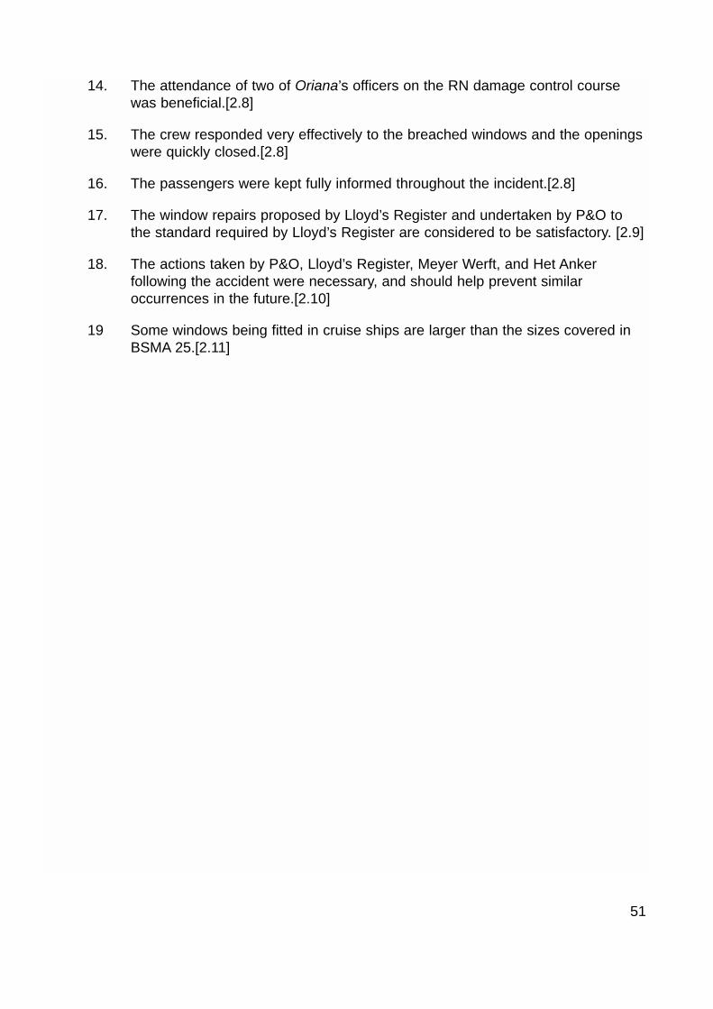
14. The attendance of two of Oriana’s officers on the RN damage control coursewas beneficial.[2.8]
15. The crew responded very effectively to the breached windows and the openingswere quickly closed.[2.8]
16. The passengers were kept fully informed throughout the incident.[2.8]
17. The window repairs proposed by Lloyd’s Register and undertaken by P&O tothe standard required by Lloyd’s Register are considered to be satisfactory. [2.9]
18. The actions taken by P&O, Lloyd’s Register, Meyer Werft, and Het Ankerfollowing the accident were necessary, and should help prevent similaroccurrences in the future.[2.10]
19 Some windows being fitted in cruise ships are larger than the sizes covered inBSMA 25.[2.11]
51
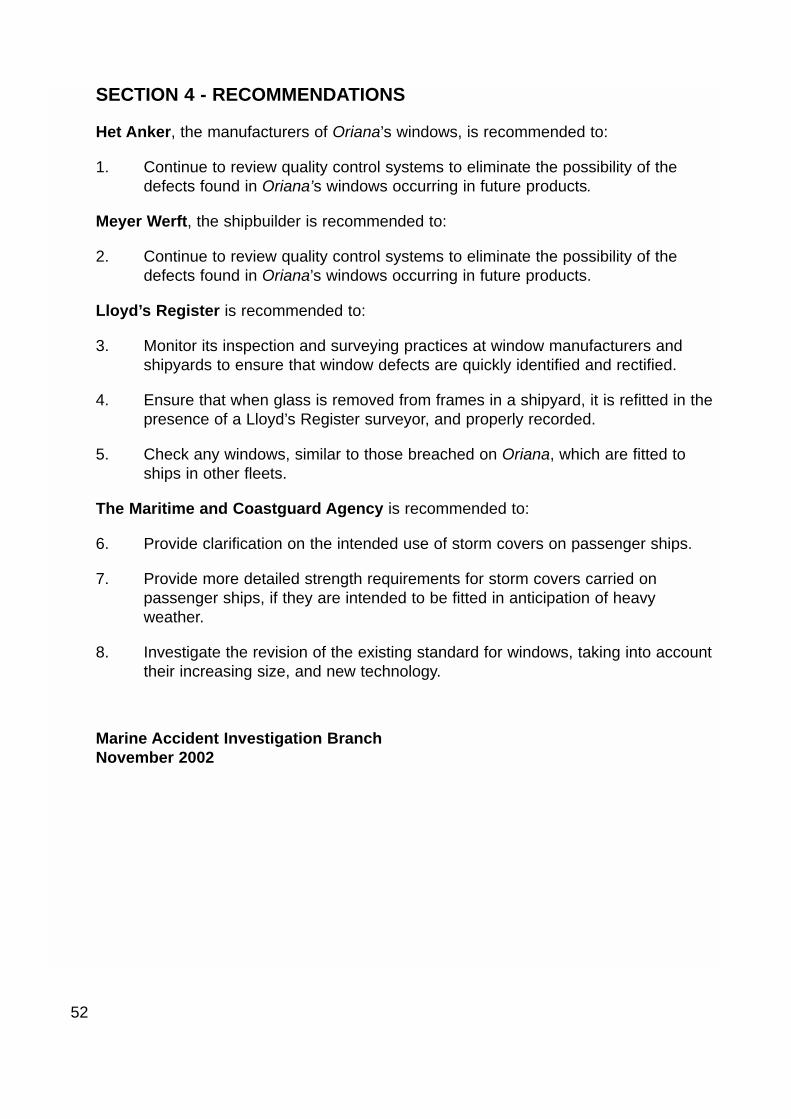
SECTION 4 - RECOMMENDATIONS
Het Anker, the manufacturers of Oriana’s windows, is recommended to:
1. Continue to review quality control systems to eliminate the possibility of thedefects found in Oriana’s windows occurring in future products.
Meyer Werft, the shipbuilder is recommended to:
2. Continue to review quality control systems to eliminate the possibility of thedefects found in Oriana’s windows occurring in future products.
Lloyd’s Register is recommended to:
3. Monitor its inspection and surveying practices at window manufacturers andshipyards to ensure that window defects are quickly identified and rectified.
4. Ensure that when glass is removed from frames in a shipyard, it is refitted in thepresence of a Lloyd’s Register surveyor, and properly recorded.
5. Check any windows, similar to those breached on Oriana, which are fitted toships in other fleets.
The Maritime and Coastguard Agency is recommended to:
6. Provide clarification on the intended use of storm covers on passenger ships.
7. Provide more detailed strength requirements for storm covers carried onpassenger ships, if they are intended to be fitted in anticipation of heavyweather.
8. Investigate the revision of the existing standard for windows, taking into accounttheir increasing size, and new technology.
Marine Accident Investigation BranchNovember 2002
52

53
Ilustration of hogging
Fig
ure
28
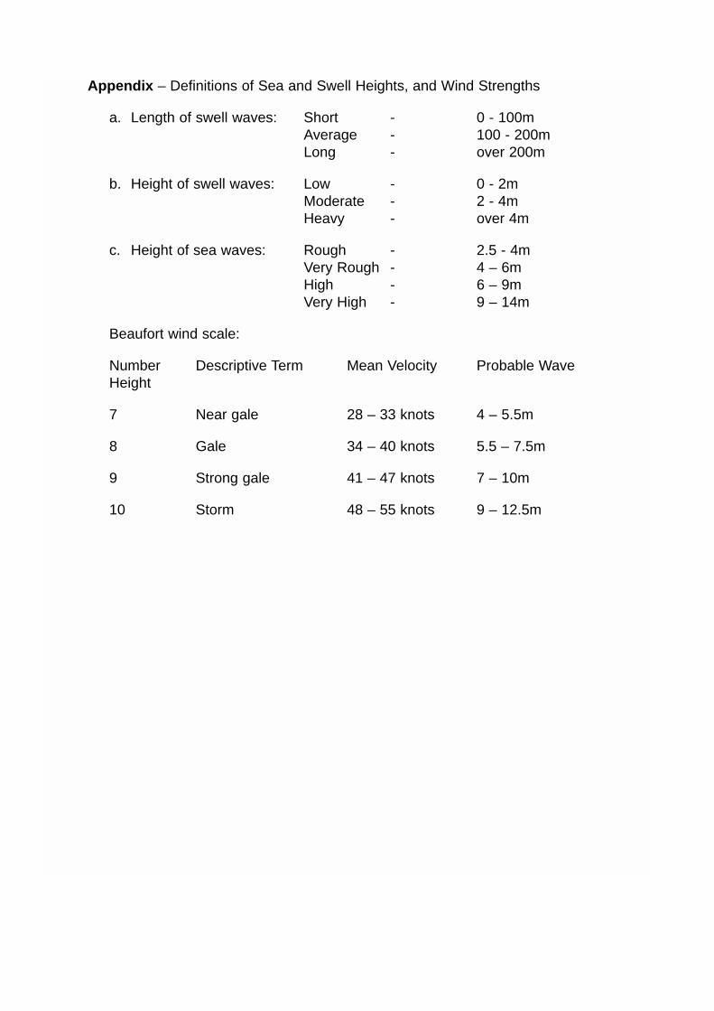
Appendix – Definitions of Sea and Swell Heights, and Wind Strengths
a. Length of swell waves: Short - 0 - 100mAverage - 100 - 200mLong - over 200m
b. Height of swell waves: Low - 0 - 2mModerate - 2 - 4mHeavy - over 4m
c. Height of sea waves: Rough - 2.5 - 4mVery Rough - 4 – 6mHigh - 6 – 9mVery High - 9 – 14m
Beaufort wind scale:
Number Descriptive Term Mean Velocity Probable Wave Height
7 Near gale 28 – 33 knots 4 – 5.5m
8 Gale 34 – 40 knots 5.5 – 7.5m
9 Strong gale 41 – 47 knots 7 – 10m
10 Storm 48 – 55 knots 9 – 12.5m