ordnance maintenance - internet archive
TRANSCRIPT

^ CT3•x,
»
WAR DEPARTMENT TECHNICAL MANUAL
ORDNANCE MAINTENANCE
Semitrailer MIS, Component of 40-Ton Tank Transporter Trailer
Truck M25.;*'. 1 | m *»• UNIT
WAS. DEPARTMENT • 17 FEBRUARY 1944

WAR DEPARTMENT TECHNICAL MANUAL TM 9-1767E
ORDNANCE MAINTENANCE
Semitrailer Ml5, Component of40-Ton Tank Transporter Trailer
Truck M25
WAR DEPARTMENT • 17 FEBRUARY 1944

WAR DEPARTMENT Washington 25, D. C, 17 February 1944
TM 9-1767E, Ordnance Maintenance: Semitrailer M15, Com ponent of 40-Ton Tank Transporter Trailer Truck M25, is published for the information and guidance of all concerned.
r A.G. 300.7 (10 Aug43) "I O.O.M. 461/(TM 9) RA (18 Feb 44)
By ORDER OF THE SECRETARY OF WAR:
G. C MARSHALL,Chief of StaS.
OFFICIAL:J. A. ULIO,
Major General,The Adjutant General.
DISTRIBUTION: R 9 (4); Bn 9 (2); C 9 (8).
(For explanation of symbols, see FM 21-6.)
CONTENTS
TM 9-1767E
Poragrapht Pag*'
CHAPTER 1. INTRODUCTION .............. 1-2 4-7
CHAPTER 2. BRAKE SYSTEM ............. 3-21 8-23SECTION I. Slack adjuster .............. 3-6 8-9
II. Internal brake .............. 7-12 10-14III. Relay-emergency valve ....... 13-21 14-23
CHAPTER 3. UNDER CARRIAGE AND SUSPEN SION ASSEMBLY (UNDERCON- STRUCTION) .............. 22-27 24-30
^^SEGTION L Trunnion axle .............. 22-24 24-26
II. Walking beam and trunnionshaft .................... 25-27 27-30
CHAPTER 4. FRAME AND MISCELLANEOUSPARTS ................... 28-39 31-42
SECTION I. Wheel cable guide ........... 28-29 31-32II. Cable roller ................ 30-31 32-33
III. Supports ................... 32-33 33-36IV. Trolley hoist ............... 34-39 37-42
CHAPTER 5. WHEELS, HUBS, AND DRUMS . . . 40-45 43-46SECTION I. Hubs ..................... 40-42 43-45
II. Drums .................... 43-45 45-46
REFERENCES ........................... 47-48
INDEX ............................. .... 49-51

TM 9-1767E 1-2
ORDNANCE MAINTENANCE - SEMITRAILER Ml 5, COMPONENT OF 40-TON TANK TRANSPORTER TRAILER TRUCK M25
CHAPTER 1
INTRODUCTIONParagraph
Scope .................................:............ 1MWO and major unit assembly replacement record ......... 21. SCOPE.
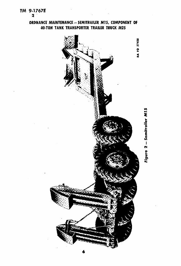
a. The instructions contained in this manual are for the informa tion and guidance of personnel charged with the maintenance and repair of the Semitrailer MIS which is a component of the 40-ton Tank Transporter Trailer Truck M25 (figs. 1 and 2). This manual does not contain information which is intended primarily for using arms, since such information is available to ordnance maintenance personnel in TM 9-767.
b. This manual contains a description of and procedure for disas sembly, inspection, repair, and assembly of the slack adjuster, internal brake assembly, relay-emergency valve, trunnion axle, walking beam, supports, hoist, hubs, drums, and related items. ~ ~
c. TM 9-767 contains operating and organizational maintenance instructions for the 40-ton Tank Transporter Trailer Truck M25, of which the Semitrailer M15 is a part.
d. Ordnance maintenance instructions for the Tractor Truck M26, which is the forward component of the 40-ton Tank Transporter Trailer Truck M25, are contained in the following:
(1) TM 9-1767A covers the engine and engine accessories.(2) TM 9-1767B covers the power train.(3) TM 9-1767C covers the body, chassis, and winches.
2. MWO AND MAJOR UNIT ASSEMBLY REPLACEMENTRECORD.
a. Description. Every vehicle is supplied with a copy of AGO Form No. 478, which provides a means of keeping a record of each MWO (FSMWO) completed or major unit assembly replaced. This form includes spaces for the vehicle name and U. S. A. registra tion number, instructions for use, and information pertinent to the work accomplished. It is very important that the form be used as directed, and that it remain with the vehicle until the vehicle is removed from service.
b. Instructions for Use. Personnel performing modifications or major unit assembly replacements must record clearly on the form a description of the work completed, and must initial the form in the

TM 9-1767E2
INTRODUCTION
8 Sa
O
o
I
o
I
TM 9-1767E 2
ORDNANCE MAINTENANCE - SEMITRAILER Ml5, COMPONENT OF 40-TON TANK TRANSPORTER TRAILER TRUCK M25
J) '5
I
«3

TM 9-1767E 2
INTRODUCTION
columns provided. When each modification is completed, record the date, hours and/or mileage, and MWO number. When major unit assemblies, such as engines, transmissions, or transfer cases, are re placed, record the date, hours and/or mileage, and nomenclature of the unit assembly. Minor repairs and minor parts and accessory replacements need not be recorded.
c. Early Modifications. Upon receipt by a third or fourth echelon repair facility of a vehicle for -modification or repair, mainte nance personnel will record the MWO numbers of modifications ap plied prior to the date of AGO Form No. 478.

TM 9-1767E 3-5
ORDNANCE MAINTENANCE - SEMITRAILER Ml 5, COMPONENT OF 40-TON TANK TRANSPORTER TRAILER TRUCK M25
CHAPTER 2 BRAKE SYSTEM
Section I SLACK ADJUSTER
Paragraph
Description and data ................................. 3Test ............................................... 4Disassembly, cleaning, inspection, and assembly ........... 5Fits and tolerances ................................... 63. DESCRIPTION AND DATA.
a. Description. The slack adjusters (fig. 3) act as brake levers, and also provide a quick and easy method of adjusting the brakes. The slack adjusters are mounted on the brake camshafts, and are attached to the equalizers. Air pressure in the brake cylinder moves the slack adjusters and the camshafts, thus expanding the shoes against the brake drums.
b. Data. Make ............................ Fruehauf Trailer CompanyModel ............................................. 51430Weight ........................................... 2 3/4 IbLength of leverage .................................... 6 in.Quantity per trailer ...................................... 84. TEST.
a. Place arm end of slack adjuster in vise with the adjusting screw up. Try turning adjusting screw with an 8-inch wrench. If adjust ing screw fails to turn, this indicates the assembly lacks lubrication, a tooth is stripped on gear, or worm gear is broken. Replace the worn and defective parts. After testing worm assembly, place a Vfe-inch rod end pin through bushing. If pin is extremely loose, replace the bushing.5. DISASSEMBLY, CLEANING, INSPECTION, AND ASSEMBLY.
a. Disassembly (fig. 3). Screw out worm assembly in a counter clockwise direction, and remove assembly and lock washer from hoCis- ing. NOTE: Do not disassemble the worm assembly. Pry snap ring out of adjuster housing. Lift out felt retainer, outer felt, worm gear, and inner felt. Remove lubrication fitting. Press bushings out of slack adjuster arm.
b. Cleaning and Inspection.(1) Remove all grease from slack adjuster housing. Wash housing
and all parts in dry-cleaning solvent8

TM 9-1767E 5-6
LUBRICATION FITTING*N
HOUSING
BRAKE SYSTEM
WORM GEAR
WORM ASSEMBLY
LOCK WASHER
• BUSHING
SNAP RING
RA PD 57416
Figure 3 — Slack Adjuster — Disassembled
(2) Inspect worm gear for broken or sheared teeth and excessive wear. Replace if unserviceable. Check worm assembly for cracks, sheared or broken teeth, or worn threads. If defective, replace. After testing worm assembly, test bushing in slack adjuster arm for excessive wear by inserting l/z -inch rod end pin through bushing. If pin fit is extremely loose, replace bushing (subpar. c, following). Check felts for wear and evidence of disintegration. Secure replace ment if necessary.
c. Assembly. Press bushing into slack adjuster arm. Install lu brication fitting in adjuster housing. Place several drops of engine oil on the two felt washers, and work the oil into the felts. Install one felt in cavity of adjuster housing. Coat surface of teeth of worm gear with GREASE, general purpose, No. 1. Install worm gear in housing next to felt. Place other felt next to gear. Install felt retainer next to felt. Secure felt retainer to housing with snap ring, and make certain snap ring is fully seated in groove in housing. Place arm end of slack adjuster in vise with worm assembly hole up. Coat surface of worm assembly with general purpose grease No. 1. Place lock washer over worm. Turn worm assembly into housing and tighten. Fill housing with general purpose grease, using grease gun.
6. FITS AND TOLERANCES. a. Bushing.
Ream diameter .................................... 0.501 in.Outside diameter ................................... 0.628 in.Length ............................................. % in.

TM 9-1767E 7-8
ORDNANCE MAINTENANCE - SEMITRAILER Ml 5, COMPONENT OF 40-TON TANK TRANSPORTER TRAILER TRUCK M25
Section II
INTERNAL BRAKEParagraph
Description and data ................................. 7Disassembly of internal brakes into subassemblies .......... 8Brake shoes ......................................... 9Adapter ............................................ 10Assembly of subassemblies ............................. 11Fits and tolerances .................................... 12
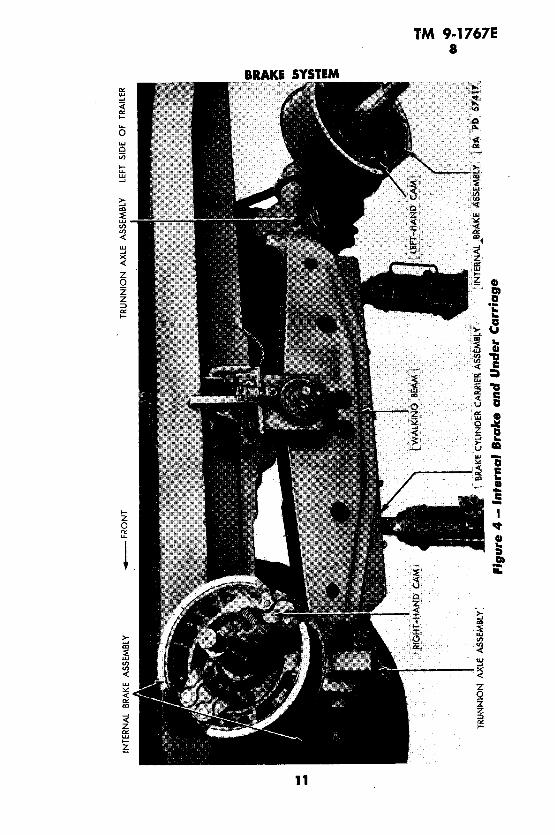
7. DESCRIPTION AND DATA.a. The brakes (fig. 4) are of the internal-expanding, double-anchor,
two-shoe type. The shoes are operated by an S-type cam. The brake shoes are mounted on eccentric anchor pins and a cam. The camshaft is provided with a 360-degree slack adjuster. The camshaft is car ried on a self-alining, ball-bearing plus needle bearing to prevent drag. The brakes are actuated by four air cylinders mounted in the hollow section of the walking beam. Forward ^movement of the cylinders operates the camshaft, which expands the two shoes against the drum.
b. Data. Make ............................ .Fruehauf Trailer CompanyModel ......................................... SP PL 480Weight ............................................. 94 IbQuantity used .......................................... 8Diameter of shoes .................................... 16 in.Width of shoes ....................................... 6 in.Number of mounting bolts ................................. 8Number of linings per shoe- ............................... 28. DISASSEMBLY OF INTERNAL BRAKES INTO SUBASSEM
BLIES.a. Remove Brake Shoes. Remove brake assembly from vehicle
as outlined in part III of TM 9-767. Remove anchor pin bracket from the assembly by tapping bracket off anchor pins with a light hammer. Remove the two shoes from the assembly by pulling shoes off anchor pins and S-cam. Remove the two 3/s-inch bolts holding guide return spring to the shoe assemblies.
b. Adapter. Remove six cap screws holding dust shields to mount ing plate adapter. Pry snap ring out of groove in camshaft, and pull snap ring, felt retainer, and felt washer off cam. Pull cam out of adapter. Remove the two locking nuts holding the two anchor pins in the adapter. Drive out the anchor pins.
10
INTE
RNAL
BR
AKE
ASSE
MBL
Y- F
RO
NT
TRU
NN
ION
AX
LE
ASSE
MBL
Y LE
FT
SIDE
OF
TRAI
LER
-2TR
UN
NIO
N A
XLE
ASSE
MBL
YBR
AKE
CYL
IND
ER C
ARRI
ER A
SSEM
BLY"
, ! I
NTE
RN
AL
JBR
AK
E AS
SEM
BLY-
' { R
A PO
57
417,
Fig
ure
4 - In
fern
al
Bra
ke a
nd
Un
der
Ca
rria
ge

TM 9-1767E 8-9
ORDNANCE MAINTENANCE - SEMITRAILER Ml 5, COMPONENT OF 40-TON TANK TRANSPORTER TRAILER TRUCK M25
B D E
A CAM SHAFT SNAP RING
B FELT RETAINER
C FELT WASHER
D CAP SCREW
E LOCK WASHER
F DUST SHIELD L, H.
G DUST SHIELD R. H.
H ANCHOR PIN LOCK NUTS
I NEEDLE BEARING
J LUBRICATION FITTING
K BRAKE MOUNTING PLATE ADAPTER
L NUT
M LOCK WASHER
N CAP SCREW
O BRAKE ECCENTRIC ANCHOR PINS
S T
P BRAKE LINING
Q BRAKE LINING SCREWS
R CAM (L. H. SHOWN)
S NUT
T LOCK WASHER
U BRAKE SHOE ROLLER
V ROLLER SHAFT
W BRAKE SHOE
X LOCK WASHER
Y NUT
Z OILITE SHOE BUSHING AA BRAKE SHOE SPRING
AB CAP SCREWS
AC BRAKE ANCHOR PLATE BRACKET
AD CAP SCREW RA PD 57418
Figure'5 — Internal Brake Assembly — Disassembled9. BRAKE SHOES.
a. Cleaning. Steam-clean all parts, including lining.b. Disassembly. Remove all cap screws, lock washers, and nuts
holding lining to shoes. NOTE: // lining is to be reinstalled on shoe after disassembly, mark each lining and shoe for reassembly. Roller shaft is held in shoe by four heavy punch marks. Try turning roller by hand. If roller fails to rotate, drive out roller shaft, and remove roller. NOTE: Brake shoe bushings are of the Oilite-type, and re placement is rarely necessary. If bushings are excessively worn or out-of-round, press out the bushings.
c. Repair.(1) BUSHING REPLACEMENT. Press one bushing into bushing bore,
leaving the end of bushing flush with face of shoe. Press other bushing12

TM 9-1767E 9-11
BRAKE SYSTEM
into bushing bore from opposite side in the same manner. Shoe bush ings come reamed to proper diameter. Try anchor pin through bush ings for size. If reaming is necessary, ream to 1.132 inches (par. 12).
(2) ROLLERS. Position roller in slotted section of shoe. Aline hole in roller with shaft hole in shoe. Secure roller to shoe by driving roller shaft into position in roller bosses, using a soft hammer. Anchor roller shaft in shoe by placing four heavy center punch marks in shoe bosses adjacent to shaft at four different places equally spaced around end of roller shaft. CAUTION: When making punch marks do not strike roller shaft with punch.
(3) LINING. Remove all rust on surface of shoes. Place a screw in hole of brake lining. If screw head projects out beyond countersunk surface, discard lining. Secure the four linings to shoes using four screws, lock washers, and nuts in each lining. Fasten the guide return spring to the two shoes, using two 3/s-inch bolts and lock washers.10. ADAPTER.
a. Disassembly. Needle bearings are a pressed fit. Prior to dis assembly, place finger on needle bearings, and try to rotate rollers. If rollers do not revolve, press out the two needle bearing assemblies. Remove lubrication fitting.
b. Cleaning. Clean all parts, using SOLVENT, dry-cleaning. Polish the eccentric surface of anchor pins, using 5/0-180 abrasive cloth. Inspect inner surface of needle bearing hole for burs and scraped metal surface. Remove burs with a round file.
c. Repair. Check adapter for sheared dust shield cap screws. If a broken screw is found, remove broken portion. Check diameter of needle bearing hole (par. 12). Check threads in lubrication hole, and clean worn thread by retapping. Check diameter of anchor pin holes, making certain they are not out-of-round (par. 12).
d. Assembly. Press one needle bearing into adapter. Press needle bearing into bore of adapter until bearing is in %e inch beyond outer face of adapter. Press other needle bearing into adapter bore from opposite side in the same manner. Place a light film of grease over inner surface of anchor pins. Place the two anchor pins in anchor pin holes. Install the four lock nuts on the two anchor pins, but do not tighten.11. ASSEMBLY OF SUBASSEMBLIES.
a. Place light film of general purpose grease No. 1 over surface of anchor pins, and in the space between the two shoe bushings. Fill the space between the two needle bearings with general purpose grease. Work the grease between each of the rollers. Place the cam through adapter. Place felt over shaft end. Place retainer next to felt. Move the felt and retainer next to adapter. Secure felt and retainer to camshaft, using snap ring. Place upper shoe assembly half-
13

TM 9-1767E 11-13ORDNANCE MAINTENANCE - SEMITRAILER MIS, COMPONENT OF
40-TON TANK TRANSPORTER TRAILER TRUCK M25
way onto anchor pins, with the roller end of shoe resting on S-cam. Place pry bar between lower shoe assembly and adapter. Pry down on lower shoe, working shoe on anchor pin and S-cam. Coat upper and lower surfaces of S-cam with general purpose grease No. 2. Install the two dust shields, but do not tighten cap screws holding dust shield to adapter. NOTE: Cap screws holding dust shield to adapter, and the four nuts holding anchor pins, should not be tight ened until after brake assembly is installed on trailer axle. These parts must be removed to accomplish major brake adjustment in accordance with procedure outlined in TM 9-767.
12. FITS AND TOLERANCES.
a. Description.
AdapterAnchor pin hole ...........Needle bearing hole ........Anchor pin at eccentric ......
Brake shoesBushing outside diameter ....Bushing ream diameter (after
assembly) ..............Bushing length ............Lining ...................Brake shoe bushing hole .....
Max.(in.)
Min. Desired(in.) (in.)
Replace Beyond
(in.)
1.002 1.000 1.001 0.968751.750 1.750 1.750 1.749951.129 1.125 1.127 1.0
1.3155
1.132 . 1.01.00.75 0.251.313 1.2805
Section III RELAY-EMERGENCY VALVE
ParagraphDescription and data ................................ 13Test .............................................. 14Disassembly of relay-emergency valve into subassemblies. . . 15Check valve and diaphragm assembly .................. 16Emergency valve body ............................... 17Valve plunger and diaphragm .......................... 18'Valve and cage assembly ............................. 19Lower valve body ................................... 20Assembly of subassemblies ............................ 21
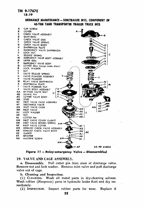
13. DESCRIPTION AND DATA.a. Description. The relay-emergency valve (fig. 11) serves as a
relay station.to speed up the application or release of the trailer brakes, and also provides a means of automatically applying the
14

TM 9-1767E 13-14
BRAKE SYSTEM
trailer brakes in case the trailer breaks away from the tractor. Fundamentally, its function is to operate so as to deliver and main tain the same air pressure in the trailer brake cylinders as the brake valve on the tractor delivers to it.
b. Data.Make ............................ Midland Steel Products Co.Model ........................................... .N2504AWeight ............................................ .71/2 lbInterchangeable with Bendix-Westinghouse ............ PC22035314. TEST (figs. 6 and 11).
a. Couple Relay-emergency Valve to Test Stand. Using West- inghouse portable test stand, connect the relay-emergency valve to test stand in the same relative position as shown in piping diagram (fig. 6). Install one pipe plug in port marked "CYL" (cylinder); install one pipe plug in port marked "RES" (reservoir). Remove exhaust valve.
b. Test Compensating Characteristics. A properly functioning valve will admit the same air pressure to the brake cylinder (gage "A") as is admitted to the service line (gage "B"). Admit air in the emergency and service lines. Operate the tractor valve and observe gages "A" and "B". Unbalanced pressures indicate that the by-pass port in the discharge valve is plugged. Slow response in gage "A" in dicates that the plunger is corroded and sticking. Disassemble and clean (par. 15).
c. Test for Leakage in Release Position. Admit air to emer gency line; disconnect service line. Apply soapy water to the ex haust port and to service line coupling. A 3-inch bubble in 10 seconds is permissible. Excessive leakage at exhaust port is caused "by a worn check valve body or a worn upper seal. Replace check valve body and upper seal. Excessive leakage at service line connection is caused by a dirty or worn inlet valve. Clean or replace inlet valve.
d. Test Leakage in Applied Position. Admit air to emergency and service lines, and apply soapy water to exhaust port. Permis sible leakage at 20 pounds pressure in service line must not exceed a 3-inch bubble in 10 seconds. Excessive leakage is caused by one of the following:
(1) WORN OR DIRTY DISCHARGE VALVE. Clean or replace.(2) WORN DISCHARGE VALVE PLUNGER. Replace plunger.(3) WORN LOWER SEAL. Replace lower seal.(4) WORN CHECK VALVE PLUNGER. Replace check valve plunger.(5) WORN UPPER SEAL. Replace upper seal.e. Test Leakage in Emergency Position. Admit air to emergency
line. Disconnect emergency line coupling. Disconnect service line coupling. Observe gages "A" and "B". Apply soapy water to exhaust
15

TM 9-1767E; 14
ORDNANCE MAINTENANCE-SEMITRAILER MIS, COMPONENT OF 40-TON TANK TRANSPORTER TRAILER TRUCK M25
AIR RESERVOIR PORT
PIPE PLUG
RA PD 318226
Figure 6 — Piping Diagram for Testing Relay-emergency Valve
16

TM 9-1767E 14-15
BRAKE SYSTEMCHECK VALVE AND DIAPHRAGM EMERGENCY RELEASE SPRING
COVER SEAL (SMALL INSIDE DIA.) RA PD 57419
Figure 7 — Removing Check Valve and Diaphragm Assembly
port and to emergency line coupling. If gage "A" fails to show pres sure when the emergency line coupling is disconnected, the failure is due to a frozen check valve plunger, frozen check valve disk, or a defective emergency valve diaphragm. Excessive leakage at exhaust port is caused by a worn or dirty discharge valve. Clean or replace discharge valve. Leakage at emergency line coupling is caused by a defective check valve disk, or a defective emergency valve dia phragm. Replace check valve disk or emergency valve diaphragm. Excessive leak at service line port is caused by a defective by-pass valve seat, or a defective relay valve diaphragm. Replace worn or damaged parts.
15. DISASSEMBLY OF RELAY-EMERGENCY VALVE INTOSUBASSEMBLIES.
a. Remove Check Valve and Diaphragm Assembly (fig. 7). With the valve held firmly in vise, remove six cap screws, six nuts, and six lock washers holding cover to body. Pry cover off emergency valve body. Lift out check valve and diaphragm assembly and emer-
17

TM 9-1767E 15
ORDNANCE MAINTENANCE - SEMITRAILER Ml5, COMPONENT OF 40-TON TANK TRANSPORTER TRAILER TRUCK M25
EMERGENCY VALVE BODY VALVE RELEASE SPRING BY-PASS VALVE SEAT
VALVE PLUNGER AND DOWEL PINDIAPHRAGM ASSEMBLY RA PD 57420
Figure 8 — Removing Valve Body and Valve Plunger Assembly
gency release spring. CAUTION: When prying cover off emer gency valve body, use care not to puncture diaphragm.
b. Remove Valve Body and Valve Plunger Assembly (fig. 8). Remove six cap screws, six lock washers, and six nuts holding emer gency valve body to lower valve body. Pry emergency valve body and lower valve body apart. Lift out valve release spring, dowel pin, valve plunger and diaphragm assembly from emergency valve body. CAUTION: When prying emergency valve body from valve body, use care not to puncture relay valve diaphragm.
c. Remove Inlet Valve Cage Assembly (fig. 9). Remove four nuts and four lock washers from four studs holding inlet valve cover t9 lower valve body. Lift off inlet valve cover and gasket. Lift out inlet valve return spring. Lift out inlet valv.e cage and valve assem bly. Remove gasket
18

TM 9-1767E 15-16
BRAKE SYSTEM
INLET VALVE NUT GASKET LOCK WASHER COTTER PIN
VALVE AND CAGE ASSEMBLY INLET VALVE RETURN SPRING GASKET INLET VALVE COVER RA PD 57426
Figure 9 — Removing Valve and Cage Assembly
16. CHECK VALVE AND DIAPHRAGM ASSEMBLY.a. Disassembly (fig. 10). Depress disk with thumb. Pry out
snap ring holding check valve disk in check valve body. Lift out check valve disk and check valve spring. With two wrenches, re move nut from valve body. Separate diaphragm plates from dia phragm. CAUTION: Do not attempt to remove nut from valve body with assembly in vise. Vise jaws will score face of valve body.
b. Cleaning. Steam-clean all metal parts. Wipe rubber (Neo-
19

TM 9-1767E 16
ORDNANCE MAINTENANCE - SEMITRAILER Ml5, COMPONENT OF 40-TON TANK TRANSPORTER TRAILER TRUCK M25
EMERGENCY VAIVE DIAPHRAGM
CHECK VALVE DISK - , DIAPHRAGM PLATE CHECK VALVE SPRING SNAP RING VALVE BODY RA PD 57427
Figure 10 — Disassembly of Check Valve Body and Diaphragm
prene) portion of check valve disk with cloth entirely free from grease and oil. Scrape sealing compound off disk shaft with putty knife.
c. Inspection. Inspect rubber in check valve disk assembly. If a deep groove is worn in rubber, replace. Inspect check valve spring. If badly corroded, replace spring. Check emergency valve diaphragm. If the rubber appears checked or shows signs of wear, replace dia phragm.
d. Assembly. Place a light coat of type A sealing compound around shoulder of valve body plunger. With plunger nose up, place one diaphragm plate against plunger shoulder (bevel edge of plate must be up). Place diaphragm over check valve body seat with the word "TOP" embossed on diaphragm, down. Place diaphragm plate over check valve body with the beveled edge against diaphragm. Place a light coat of type A sealing compound on plunger threads and face of nut. Install nut and tighten, using two wrenches (fig. 9). Lock the nut to check valve seat by placing two sharp punch marks
20

TM 9-1767E 16-18
BRAKE SYSTEM
in face of nut and threads. Place punch marks directly opposite each other. Place check valve spring in cavity at top of valve body. Place check valve disk assembly on top of spring with the rubber surface down. Lock the spring and check valve disk in position, using snap ring (fig. 11).
17. EMERGENCY VALVE BODY.a. Cleaning and Inspection. Wash all parts in dry-cleaning sol
vent. Blow out air port with compressed air. Clean sealing com pound off outer surface of seals, using penknife. Check lip of leather seals for excessive wear. Check body for cracks. Replace damaged parts.
b. Disassembly. Do not remove seals if they are not damaged. Seals are of a pressed fit and will become damaged when removed. Drive out the damaged seal or seals, using a Winch, long-tapered punch with a blunt end.
c. Assembly. Coat outer edge of seals with a light coat of type A sealing compound. Press the two seals into emergency valve body cavity. NOTE: The seal with the smaller inside diameter is pressed into top of emergency valve body (the cavity with the smallest stop flange). When pressing seals in, make certain that the free lip of seals is toward the outside.
18. VALVE PLUNGER AND DIAPHRAGM.a. Cleaning and Inspection.(1) CLEANING. Clean all metal parts in dry-cleaning solvent.
Wash rubber (Neoprene) parts in hydraulic brake fluid and dry im mediately.
(2) INSPECTION. Inspect diaphragm for cracks and signs of wear. Inspect valve plunger for cracks. Inspect the four air ports, and make certain they are open. Secure replacements if parts are not service able.
b. Disassembly (figs. 8 and 9). Place valve plunger in vise. Do not permit vise jaws to contact small diameter of plunger; clamp on at the IVa-inch diameter. Remove valve plunger nut. Lift off diaphragm plate and relay valve diaphragm.
c. Assembly. Place relay valve diaphragm over valve plunger. Place diaphragm plate over valve plunger next to relay valve dia phragm. Coat threads, face of nut, and face of diaphragm plate with type A sealing compound. Secure diaphragm and diaphragm plate to valve plunger with valve plunger nut. Wipe all excess sealing compound from the assembly. Lock valve plunger nut in position by placing four punch marks spaced equally around face of nut adjacent- to plunger.
21
TM 9-1767E 18-19
ORDNANCE MAINTENANCE - SEMITRAILER Ml5, COMPONENT OF 40-TON TANK TRANSPORTER TRAILER TRUCK M25
A CAP SCREWB COVERC CHECK VALVE ASSEMBLYD SNAP-RINGE CHECK VALVE DISKF CHECK VALVE SPRINGG CHECK VALVE BODYH DIAPHRAGM PLATEJ EMERGENCY VALVE DIAPHRAGMK LOCK NUTt RELEASE SPRINGM EMERGENCY VALVE BODY ASSEMBLYN UPPER SEALP EMERGENCY VALVE BODYQ LOWER SEAL (Large inside diam.)R LOCK WASHERS NUTT VALVE RELEASE SPRINGU VALVE PLUNGER ASSEMBLYV VALVE PLUNGERW RELAY VALVE DIAPHRAGMX DIAPHRAGM PLATEY ' VALVE PLUNGER NUTZ VALVE BODY ASSEMBLY
A A BY-PASS VALVE SEATAB DOWEL PINAC LOWER VALVE BODYAD STUDAE INLET VALVE CAGE ASSEMBLYAF DISCHARGE VALVEAG INLET VALVE CAGEAH INLET VALVEAJ LOCK WASHERAK NUTAL COTTER PINAM INLET VALVE COVER GASKETAN INLET VALVE RETURN SPRINGAP INLET VALVE COVERAQ EXHAUST CHECK VALVE ASSEMBLYAR EXHAUST CHECK VALVE BODYAS GASKETAT RETAINERAU MACHINE SCREW AN
AM
—B
u<
> —AP RA PD 318224
Figure 11 — Relay-emergency Valve — Disassembled
19. VALVE AND CAGE ASSEMBLY.a. Disassembly. Pull cotter pin from stem of discharge valve.
Remove nut and lock washer. Remove inlet valve and pull discharge valve out of cage.
b. Cleaning and Inspection.(1) CLEANING. Wash all metal parts in dry-cleaning solvent.
Wash rubber (Neoprene) parts in hydraulic brake fluid and dry im mediately.
(2) INSPECTION. Inspect rubber parts for wear. Replace if22

TM 9-1767E 19-21
BRAKE SYSTEM
deeply grooved or distorted. Inspect valve seat. Replace if damaged or worn.
c. Assembly. Place discharge valve in the pronged end of inlet valve cage with rubber surface toward the outside (fig. 11). Place inlet valve assembly over stem of discharge valve with the rubber surface down. Install lock washer and nut. Secure nut, using cotter pin. Coat metal surface of by-pass valve assembly with type A sealing compound.
20. LOWER VALVE BODY.a. Cleaning and Inspection.(1) CLEANING. Wash all metal parts in dry-cleaning solvent.
Wash rubber (Neoprene) parts in hydraulic brake fluid and dry im mediately.
(2) INSPECTION. Inspect body for cracks. Inspect rubber (Neo prene) seat of by-pdss valve for grooves and excessive wear.
b. Disassembly. Drive out by-pass valve seat, using Vs-inch di ameter punch. Two holes are provided in body for this purpose.
c. Assembly. Press by-pass valve seat into cavity on upper side of lower body until stop is reached.
21. ASSEMBLY OF SUBASSEMBLIES.a. Assemble Valve and Cage Assemblies. NOTE: Place a light
film of water pump grease over all friction surfaces. Do not allow any grease to contact any of the rubber assemblies (figs. 9 and 11). Place lower valve body in vise. Place gasket over the four studs. Place inlet valve and cage assembly over studs and into cavity of valve body. Place inlet valve return spring over nut at end of discharge valve stem. NOTE: Inlet valve return spring is cone-shaped; make certain the small end is installed over nut. Place gasket over studs. Place inlet valve cover over studs. Secure cover to inlet valve cage, using four nuts and four lock washers.
b. Install Valve Body (figs. 8 and 11). Place emergency valve body assembly in vise. Install dowel pin in hole provided in valve body flange. Place valve release spring over embossed section of emergency valve body. Place valve plunger and diaphragm assem bly in emergency valve body, making certain the long end is placed through seal. Secure valve body to emergency valve body, using six cap screws, nuts, and lock washers.
c. Install Check Valve and Diaphragm Assembly (figs. 7 and 11). Place emergency release spring between the three posts in emergency valve body. Place check valve assembly in spring. Place cover over diaphragm. Secure cover to emergency valve body, using six cap screws, lock washers, and nuts.
23

TM 9-1767E 22-23
ORDNANCE MAINTENANCE - SEMITRAILER Ml5, COMPONENT OF 40-TON TANK TRANSPORTER TRAILER TRUCK M25
CHAPTER 3UNDER CARRIAGE AND SUSPENSION ASSEMBLY
(UNDERCONSTRUCTION)
Section 1 TRUNNION AXLE
ParagraphDescription and data ................................ 22Cleaning, inspection, disassembly, and assembly .......... 23Fits and tolerances .................................. 24
22. DESCRIPTION AND DATA.a. Description. The trailer is equipped with four trunnion axles.
One trunnion axle is mounted on each end of the two walking beams (fig. 4). The trunnion axles allow transverse movement of the under carriage assembly, permitting one wheel to pass over a 9-inch obstacle, while the three remaining wheels remain on the ground. The trun nion axle pivots on the walking beam on two heavy bronze bushings, and is held in place by an outer thrust washer, a cotter pinned axle nut, and a hub cap (fig. 12). Two internal brake mounting flanges are integral parts of the trunnion axle. An internal brake assembly is mounted on each brake flange. The ends of the trunnion axle form spindles on which are mounted the bearings, dust collars, felts, compression rings, and axle nuts which support and secure the hub and wheel assemblies (fig. 12).
b. Data.Make ............................ Fruehauf Trailer CompanyModel ............................................. 51428Weight ............................................ 302 Ib.Quantity per trailer ...................................... 4Length ........................................... 59 s/s in.Bushings per axle ........................................ 2Diameter of inner bearing surface .................... 3.3473 in.Diameter of outer bearing surface ..................... 2.3748 in.
23. CLEANING, INSPECTION, DISASSEMBLY, AND ASSEMBLY, a. Cleaning and Inspection.(1) CLEANING. Install an axle nut on both spindles to prevent
the threads from becoming damaged while handling the axle. Re move lubrication fitting. Steam-clean the assembly.
(2) CHECK BUSHING. Check bushing for excessive wear. If worn beyond 3.875 inches, replace the bushing.
24

TM 9-1767E 23
UNDER CARRIAGE AND SUSPENSION ASSEMBLY (UNDERCONSTRUCTION)
A WALKING BEAM
B FELT RETAINER SEAL
C DOWEL PIN
D TRUNNION AXLE INNER THRUST WASHER
E TRUNNION AXLE FELT SEAL
f TRUNNION AXLE BUSHING G TRUNNION AXLE
H ELBOW 45
I LUBRICATION FITTING
J TRUNNION AXLE OUTER THRUST WASHER
K AXLE NUT
Figure 12 — Trunnion Axle —
T U V K L
L COTTER PIN
M HUB CAP
N LOCK WASHER
O CAP SCREW
P DUST COLLAR DOWEL PIN
Q DUST COLLAR
H HUB FELT
S COMPRESSION RING
T INNER BEARING
U OUTER BEARING
V AXLE D-WASHER
RA PD 57435
Disassembled
(3) CHECK SPINDLE THREADS. Check spindle threads for burs. Axle nut must turn on spindle with minimum resistance. Clean up threads by using a 6-point, NF, 12-threads-per-inch die with a thread restorer, or by turning nut onto spindle while tapping nut with a hammer.
(4) CHECK FOR BEND (fig. 13). Place axle gage in position on front side of trunnion axle with the single-pronged end of gage held firmly against the inner bearing surface. Adjust the double prongs on the opposite end of the gage until they contact the inner and outer bearing surface. Now move the gage over to the rear side of the axle, and then to the top side. If either of the double prongs fails to make contact at the rear side or the top side, a bent axle is indi cated. Use a feeler gage to determine the amount of bend. If bend is in excess of 0.010 inch, straighten axle. If checking three sides of one spindle reveals no bend, turn the gage end-for-end and check the opposite spindle in the same manner, without disturbing the setting of the prongs.
25

TM 9-1767E 23-24
ORDNANCE MAINTENANCE - SEMITRAILER Ml 5, COMPONENT OF 40-TON TANK TRANSPORTER TRAILER TRUCK M25
0.010 FEELER GAGETRUNNION AXLE
GAGE RA PD 57434
Figure 13 — Checking Trunnion Axle tor Bend
b. Disassembly. Drill out the two %-inch dowel pins (at top of axle) which prevent bushings from turning. Press out bushings on arbor press. Remove lubrication fitting.
c. Assembly. Press one bushing in until outer end of bushing is flush with outer surface of trunnion axle face. Turn trunnion axle over, and press second bushing in from opposite side, leaving the end of bushing flush with face of trunnion axle. Ream bushings to 3.750 inches (par. 24). Blow out lubrication hole with compressed air. Install lubrication fitting. Place Winch drill in each of the two holes at top side of trunnion axle, and drill a Winch hole Vi inch deep in the bushing. Drive Winch dowel pins into the two holes to prevent bushings from turning. Place several punch marks adjacent to dowel pins to prevent dowel pins from coming out.
24. FITS AND TOLERANCES, a. Description. Max.
(in.)Mln.(in.)
4.254
Desired(in.)
Replace Beyond
(in.)
Bushing (outside diameter) ..... 4.256 Bushing ream diameter (after
assembly) .................. 3.752 3.750Bushing length ................ 3.500Trunnion axle bushing hole ...... 4.252 4.250Diameter of spindle bearing surface
(inner) .................... 3.3473 3.3463Diameter of spindle bearing surface
outer ....................... 2.3748 2.3743 2.3735Spindle threads ............... National fine, 12 threads-per-inch
3.875
3.34305

TM 9-1767E 25-26
UNDER CARRIAGE AND SUSPENSION ASSEMBLY (UNDERCONSTRUCTION)
Section II WALKING BEAM AND TRUNNION SHAFT
ParagraphDescription and data ............... ................ 25Cleaning, inspection, disassembly, and assembly ........... 26Fits and tolerances .................................. 27
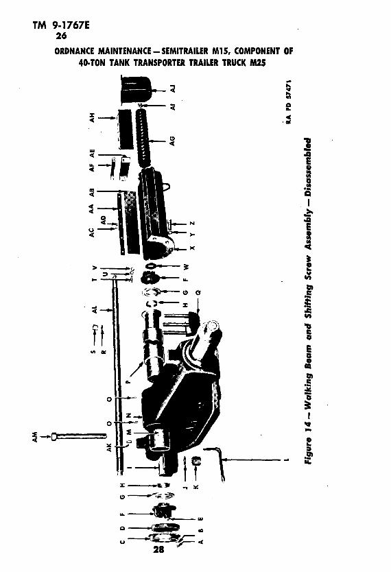
25. DESCRIPTION AND DATA.a. Description (fig. 14). The walking beam is hinged from the
trailer frame by the trunnion shaft and mounting brackets. The trunnion shaft is stationary in its mountings. The walking beam is adjustable in and out through the use of a screwing mechanism installed in the hollow of the trunnion shaft. The walking beam furnishes the longitudinal movement of the undercarriage assembly.
b. Data.(1) WALKING BEAM.
Make ............................ Fruehauf Trailer CompanyModel ............................................. 53291Weight ............................................ 450 Ib
(2) TRUNNION SHAFT. Make ............................ Fruehauf Trailer CompanyModel ..................................... ...... 565112Weight ............................................. 87 Ib
26. CLEANING, INSPECTION, DISASSEMBLY, AND ASSEM- BLY.
a. Cleaning. Place the axle nuts on both walking beam spindles to prevent threads from becoming damaged through handling. Steam- clean the assembly.
b. Inspection.(1) CHECK SPINDLES. Check the two spindles for excessive wear.
If worn beyond 3.6835 inches, replace walking beam.(2) CHECK BUSHINGS. Check inside diameter of bushings for ex
cessive wear. Replace bushing if worn beyond 4.375 inches (par. 27).(3) CHECK FOR BEND (fig. 15). Place the gage in position on front
side of walking beam, with the single-pronged end of the gage held firmly against the extreme outer end of rocker beam bearing surface. Adjust the double prongs on the other end of the gage until they contact the bearing surface. Now move the gage over to the rear side of the walking beam. If either of the two prongs fails to contact the spindle, a bend in the walking beam is indicated. Use a feeler gage to determine the amount of the bend. If it is in excess of 0.025 inch, replace walking beam. If checking both sides of one spindle
27
TM 9-1767E 26ORDNANCE MAINTENANCE - SEMITRAILER Ml5, COMPONENT OF
40-TON TANK TRANSPORTER TRAILER TRUCK M25
I-9
21
I
10)
ISi
I
I

A
1/4-
INC
H R
OUN
D HE
AD S
LOTT
ED S
CREW
B 1/
4-IN
CH
LO
CK W
ASHE
R
C DU
ST F
ELT
COVE
R
D DU
ST F
ELT
E 3/
16-IN
CH
x 2
1/2
-INC
H C
OTTE
R PI
N
F SP
ECIA
L NU
T
6
TRU
NN
ION
SHA
FT W
ASHE
R
H
SPAC
ER
I O
UTSI
DE T
RU
NN
ION
SH
AFT
CAP
J LO
CK W
ASHE
R
K CA
P BO
LT N
UT
L W
ALK
ING
BEA
M B
USHI
NG L
UBRI
CATI
ON
LINE
M
WA
LKIN
G B
EAM
BUS
HING
N
WA
LKIN
G B
EAM
(RO
CKER
ARM
)
O
BUSH
ING
DO
WEL
PIN
P TR
UN
NIO
N S
HAFT
Q
TRU
NN
ION
SHA
FT C
AP A
ND
STU
DS
R LO
CK W
ASHE
R
S NU
T
T 7/
16H
NC
H C
AP S
CREW
U 7/
16-IN
CH
LO
CK W
ASHE
R
V
7/16
-INC
H C
ASTE
LLAT
ED N
UT
W
FELT
WAS
HER
X
SHIF
TING
BRA
CKET
Y
3/4-
INC
H L
OCK
WAS
HER
Z 3/
4-IN
CH
CAP
SCR
EW
AA
SID
E W
EATH
ER S
TRIP
MO
UN
TIN
G P
LATE
AB
SI
DE W
EATH
E"
STRI
P
AC
5/
16H
NC
H C
AP S
CREW
AD
5/
16-IN
CH
LO
CK W
ASHE
R
AE
END
WEA
THER
STR
IP
AF
END
WEA
THER
STR
IP M
OU
NTI
NG
PLA
TE
A6
SHIF
TING
SCR
EW R
UBBE
R BO
OT
AH
PR
OTE
CTIO
N PL
ATE
Al
RETA
INER
COL
LAR
AJ
U-BR
ACKE
T
AK
TR
UN
NIO
N S
HAFT
DO
WEL
PIN
AL
WA
LKIN
G B
EAM
SHI
FTIN
G S
CREW
AM
TR
UN
NIO
N S
HAFT
CAP
NU
T
RA
PD 5
7471
-B
O
m 70 O
TO ii H O «
£50 I 5
o> L*
Leg
end
for
Figu
re M
- W
alki
ng B
eam
and
Shi
ftin
g Sc
rew
Ass
embl
y - D
isas
sem
bled

TM 9-17671 26-27
ORDNANCE MAINTENANCE - SEMITRAILER Ml 5, COMPONENT OF 40-TON TANK TRANSPORTER TRAILER TRUCK M25
WALKING BEAM 0.025 FEELER GAGE
GAGE RA PD 57470
Figure 15 — Cheeking Walking Beam for Bend
reveals no bend, turn gage end-for-end and check the other spindle on the opposite end without disturbing the setting of the prongs. If there is a clearance at either of the prong ends, check with a feeler gage. If the prongs are in contact at both points, the walking beam is not bent
c. Disassembly. Remove lubrication pipe extension assembly. Drill out the two Vi-inch dowel pins at top of walking beam whith prevent bushing from turning. Press out the two bushings.
d. Assembly. Press bushing in from one side so that end of bush ing is flush with the outer surface of walking beam face. Press bush ing in from opposite side in the same manner. Ream bushing to correct size (par. 27). Place a V^-inch drill in each of the two dowel pin holes, and drill a Vi-inch hole into bushings. Drive a Vi-inch dowel pin into each of the two holes to prevent bushing from turning. Rivet the dowel pin in place by making several punch marks around dowel pin edge. Install lubrication pipe extension assembly (fig. 14).27. FITS AND TOLERANCES.
i-v . . Max.a. Description. (!„.)Walking beam bushing hole .............. 5.002Spindle diameter ....................... 3.747Bushing (outside diameter) .............. 5.006Bushing (ream diameter) ............... 4.252Trunnion shaft ........................ 4.242
Milt.(in.)
5.0003.7455.0044.2504.240
Replace Beyond
(in.)
4.275
Whenextremelyscored orgrooved.
30

TM 9-1767E 28-29
CHAPTER 4 FRAME AND MISCELLANEOUS PARTS
Section I WHEEL CABLE GUIDE
ParagraphDescription and data ................................. 28Disassembly, cleaning, inspection, and assembly ........... 29
28. DESCRIPTION AND DATA.a. Description. The wheel cable guide assembly (fig. 16) is
mounted on the top deck of the trailer. The two cable guide wheels are held in a support frame by two shafts. The cable end of the winch is passed between the two wheels, thus allowing the winch operator to pull from any angle desired.
b. Data. Make ............................ Fruehauf Trailer CompanyModel (wheel cable guide) ............................ 54493Model (shaft) ..................................... 600573
29. DISASSEMBLY, CLEANING, INSPECTION, AND ASSEM BLY.
a. Disassembly (fig. 16). Pull two cotter pins from the two shafts. Place small steel bar in hole provided at end of shafts, and pull the shafts out of wheels with a turning motion. Place a cant bar between the two wheels and work them out of support frame. Remove lubri cation fitting from top side of each wheel.
b. Cleaning and Inspection.(1) Steam-clean cable guide wheel and shaft
CABLE WHEEL GUIDE SUPPORT SHAFT RA PD 57472
CABLE WHEEL
I x \ ——T — CABLE ROLLER BRACKET RIVET CABLE ROLLER RIVET
Figure 16 — Wheel Cable Guide and Cable Roller Assembly
31

TM 9-1767E 29-31
ORDNANCE MAINTENANCE - SEMITRAILER MIS, COMPONENT OF 40-TON TANK TRANSPORTER TRAILER TRUCK M25
(2) Inspect drum surface of wheels for cracked welds and bent flanges. Reweld and straighten if necessary. Check shaft for exces sive wear and for bend. Straighten shaft if bent Replace if worn.
c. Assembly. Place one wheel in support frame with the lubri cation hole toward top of support frame. Place a film of wheel bear ing grease No. 2 over surface of shaft Place shaft down through support frame and wheel. Secure shaft to frame, using Winch cotter pin.
Section II CABLE ROLLER
ParagraphDescription and data ................................. 30Disassembly, cleaning, inspection, and assembly .......... 31
30. DESCRIPTION AND DATA.a. Description. The cable roller (fig. 16) is mounted on the
second crossmember from the front on the top deck. Two mounting brackets are provided to furnish bearings for the shaft The cable roller consists of a tube, shaft sleeves, and rivets. The roller revolves with the shaft The shaft revolves in the two mounting brackets. When pulling from the rear of trailer, the cable from the winch, which is mounted on the towing vehicle, is passed over the top of the cable roller. This furnishes a rolling bearing surface for the cable, preventing excessive cable wear.
b. Data. Make ............................ . Fruehauf Trailer CompanyModel .........................'...........'......... 54487Weight ............................................ 83 IbLength of tubing ................................... 31% in.Length of shaft ................................... 36Vi in.Diameter of shaft .................................... 2 in.Diameter of tubing .................................. 4Vz in.
31. DISASSEMBLY, CLEANING, INSPECTION, AND ASSEM- BLY.
a. Disassembly (fig. 16). Remove nuts, lock washers, and cap screws holding the two roller brackets to trailer crossmember. Drive the roller bracket off roller shaft Remove the assembly. Remove the lubrication fittings from the two brackets. To remove the shaft, cut the heads off the two countersunk rivets located at each end of the tubing. Use an acetylene cutting torch, or place punch mark in
32

TM 9-1767E 31-33
FRAME AND MISCELLANEOUS PARTS
the center of rivet head and drill rivet head out, using a %-inch drilL With long-tapered, J/4-mch punch, drive out the two rivets. Pull shaft out of sleeve.
b. Cleaning. Steam-clean.c. Inspection. Check roller shaft for bend, and bearing surface
for scores and excessive wear. Check inside diameter of brackets for excessive wear, cracks and sheared lubrication fittings. Check the tubing for bend. Straighten or replace.
d. Assembly (fig. 16). Place shaft into bushing. Make certain the two pin holes in shaft are in alinement with the two holes in bush ing and roller. Secure shaft and bushing to tubing, using two rivets. Peen end of pins. Bolt one roller bracket to crossmember, but do not tighten bolts. Place roller assembly in bracket. Place bracket over end of roller shaft Bolt bracket to crossmember. Tighten bolt at opposite end of shaft Install lubrication fittings into brackets, and lubricate brackets.
Section III SUPPORTS
ParagraphDescription and data ................................ 32Disassembly, cleaning, inspection, and assembly ........... 33
32. DESCRIPTION AND DATA.a. Description. The supports (fig. 20) are of the fold-up type,
and are mounted on the trailer main frame at the front of drop in frame. They support the front of the trailer when the trailer is dis connected from the towing vehicle.
b. Data.Make ........................... .Fruehauf Trailer CompanyModel ............'......... .53805 lefthand — 53806 righthandWeight ........................................... 133 Ib
33. DISASSEMBLY, CLEANING, INSPECTION, AND ASSEM- ELY.
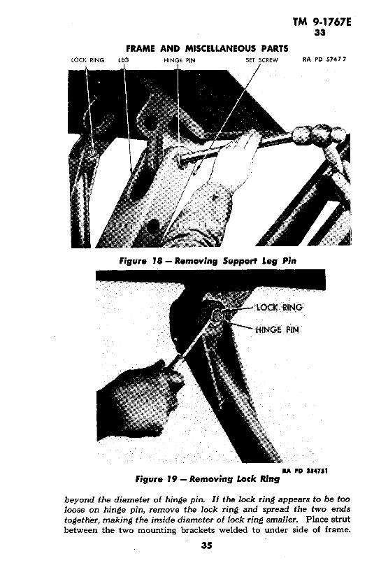
a. Disassembly. NOTE: Do not attempt to disassemble support unless trailer is coupled to towing vehicle or properly jacked up at front end. Remove cotter pin from gravity pin holding support leg in the up position, and lower the support leg (fig. 17). Remove lock ring from one side of leg hinge pin and drive pin out. Place screw driver under slot in lock ring, and pry lock ring off hinge pin. Remove lock nut and set screw from rear side of strut, and drive the two hinge pins out (figs. 18 and 19). Lift strut out

TM 9-1767E 33
ORDNANCE MAINTENANCE - SEMITRAILER M15, COMPONENT OF 40-TON TANK TRANSPORTER TRAILER TRUCK M25
STRUT GRAVITY PIN
57476
Figure 17 —Removing Support leg
b. Cleaning. Steam-clean all parts.c. Inspection. Check all grooves in hinge pins to make certain
the ends are not burred. Remove burs if present. Inspect lock rings to make certain the inside diameter has not been distorted and spread open beyond % inch in diameter. Reduce the inside diameter of lock rings by pressing ends together with a pair of pliers.
d. Assembly (fig. 20). Place support leg between the two mount ing brackets which are welded to trailer frame. Install hinge pin. Place a lock ring over each end of hinge pin, making certain they are seated in the grooves provided. NOTE: Inside diameter of lock rings is supposed to be smaller than the outside diameter of hinge pin. However, when removing lock rings they are generally spread open
34
TM 9-1767E 33
LOCK RINGFRAME AND MISCELLANEOUS PARTS
LEG HINGE PIN SET SCREW RA PD 57477
Figure 18 — Removing Support Leg Pin
RA PD 334751Figure 19-Removing Lock Ring
beyond the diameter of hinge pin. If the lock ring appears to be too loose on hinge pin, remove the lock ring and spread the two ends together, making the inside diameter of lock ring smaller. Place strut between the two mounting brackets welded to under side of frame.
35

TM 9-1767E 33
ORDNANCE MAINTENANCE - SEMITRAILER Ml 5, COMPONENT OF 40-TON TANK TRANSPORTER TRAILER TRUCK M25
D F G E D
A PIN WITH HANDLE
B LEG
C REAR HINGE PIN
D LOCK RINGS
E HINGE PIN
F SET SCREW
G SET SCREW LOCK NUT
H HINGE PIN
I LOCK PIN
J SUPPORT STRUT
K CHAIN AND SPRING COTTER PIN RA PD 57478
Figure 20 — Supports — Disassembled
Secure the vertical part of strut to frame mounting bracket, using the large hinge pin. Turn lock nut on the set screw. Install set screw in top of strut and hinge pin. Place small hinge pin in strut arm. Install the two snap rings on hinge pin. Raise up on leg until pin hole in leg contacts hole in strut Install the pin with handle. Install spring cotter pin, which is attached to chain, in the pin with handle.
36

TM 9-1767E 34-35
FRAME AND MISCELLANEOUS PARTS
Section IV TROLLEY HOIST
ParagraphDescription and data ................................. 34Disassembly of trolley hoist into subassemblies ............ 35Trolley side plates .................................. 36Ratchet case ....................................... 37Pinion gear assembly .................................. 38Assembly of subassemblies ............................ 3934. DESCRIPTION AND DATA.
a. Description. The trolley hoist (fig. 21) is a component of the crane and hoist assembly. The primary use of the hoist is to remove the inner tire and wheel assembly when it becomes necessary to change a tire. However, it can be used to remove and replace any component on the trailer undercarriage.
b. Data. Make ........................ Yale and Towne Mfg. CompanyModel .................. Spur-geared army-type, Vfc-ton capacityWeight ............................................. 86 Ib35. DISASSEMBLY OF TROLLEY HOIST INTO SUBASSEM
BLIES.a. Disassembly (fig. 21). Pull cotter pin (Y) from driving pin
ion. Remove driving pinion nut (Z) and check washer (AB) from pinion. Remove the two tap bolts (W) and lock washer (X), hold ing hand chain guides (T) and (AA) to ratchet case (AR). Lift the hand chain guards off handwheel (AC). Remove nut (R) and lock washer (S) from hand chain bolt (V), and pull the hand chain guide bolt out of hand chain guide. Remove hand chain guide separator (U). Lift hand chain (AD) off handwheel (AC). Turn handwheel (AC) off disk hub (AH). Pull handwheel (AC), galvanized iron disk (AE), ratchet disk (AF), leather disk (AG), and disk hub (AH), off drive pinion. Tap disk hub key (E) out of keyway in drive pinion. Remove nut (AP), alid lock washer (AQ) from large separator (P). Remove load chain guide bolt (AK). Remove screw (AM) from the two small separators (Q) and lift side plate (O) off the separators. Screw the three separators (P and Q) out of internal gear and case (L). Remove the three screws (A) and lock washers (B) from gear cover (C), and tap gear cover off internal gear and case (L). Pull out pinion cage (K) with pinion gears and intermediate gear. Remove cotter pin (BF) from detachable shackle bolt (BL). Remove nut (BH) from detachable shackle bolt (BL). Remove the detachable shackle bolt and load chain (BD). Remove bolt (BE) from load chain guide.
37

TM 9-1767E 35
ORDNANCE MAINTENANCE - SEMITRAILER MT5, COMPONENT OF 40-TON TANK TRANSPORTER TRAILER TRUCK M25

A
SCRE
W
B LO
CK
WAS
HER
C
G
EAR
CO
VER
D
D
RIV
ING
PI
N
E D
ISK
HUB
KEY
F LU
BRIC
ATIO
N F
ITTI
NG
G
IN
TERM
EDIA
TE
GEA
R
PIN
H
BUSH
ING
(F
OR
INTE
RM
EDIA
TE
GEA
R)
I IN
TERM
EDIA
TE
GEA
R
J P
INIO
N
CA
GE
PI
N
K P
INIO
N
CA
GE
L
INTE
RN
AL G
EAR
AN
D C
ASE
M
BALL
BE
ARIN
G
N
OIL
RE
TAIN
ER
O
TRO
LLY
HO
IST
SIDE
PL
ATE
P LA
RGE
SEPA
RAT
OR
Q
SM
ALL
SEPA
RATO
R R
NU
TS
LOC
K W
ASH
ER
T H
AN
D C
HA
IN
GU
IDE
L.
H.
U
HA
ND
C
HA
IN
GU
IDE
SEPA
RAT
OR
V
H
AN
D C
HA
IN
BOLT
W
HA
ND
C
HA
IN
TAP
BOLT
X
HA
ND
C
HA
IN
TAP
BOLT
LO
CK
WAS
HER
Y
DR
IVIN
G
PIN
ION
C
OTT
ERZ
DR
IVIN
G
PIN
ION
N
UT
AA
H
AN
D
CH
AIN
G
UID
E
R.
H.A
B
CH
ECK
WAS
HER
AC
H
AN
D W
HEE
LA
D
HA
ND
C
HA
IN
16
FOO
TAE
G
ALV
AN
IZE
D
IRO
N
DIS
KA
F RA
TCHE
T DI
SKA
6
LEAT
HER
DIS
KA
H
DISK
H
UB
Al
OUT
ER
FELT
R
ETAI
NER
AJ
OUT
ER
FELT
WAS
HER
AK
LO
AD
CH
AIN
G
UID
E
BOLT
AL
PAW
L ST
UD
AM
SM
ALL
SEPA
RAT
OR
SC
REW
AN
PA
WL
AO
PA
WL
SPR
ING
AP
SEPA
RAT
OR
NU
TA
Q
LOC
K W
ASH
ERA
R
RATC
HET
CAS
EAS
A
DJU
STI
NG
N
UT
AT
LOC
K W
ASH
ER
All
AD
JUS
TIN
G W
ASH
ER
AV
DU
ST G
UAR
D
AW
TR
ACK
WH
EEL
BEAR
ING
A
X
BEAR
ING
CU
PS
AY
LU
BRIC
ATIO
N
FITT
ING
A
Z PL
AIN
TR
ACK
WH
EEL
BA
TR
ACK
WH
EEL
AXLE
BB
AX
LE
NU
T-TR
AC
K W
HEE
L BC
AX
LE
COTT
ER
BD
LOA
D
CH
AIN
9
FOO
T BE
LO
AD
C
HA
IN
TAIL
EN
D
BOLT
BF
CO
TTER
PI
N
BG
LO
AD
CH
AIN
G
UID
E BH
D
ETAC
HAP
LE S
HAC
KLE
BOLT
NU
T Bl
BO
TTO
M H
OO
K
BJ
DET
ACH
ABLE
SH
ACKL
E LI
NK
BK
BOTT
OM
C
RO
SSH
EAD
WAS
HER
BL
D
ETAC
HAB
LE S
HAC
KLE
BOLT
B
M
LOA
D
SHEA
VE
BN
ST
RIPP
ER
BO
LO
AD
SH
EAVE
KE
Y BP
LO
AD
CH
AIN
TAI
L EN
D
BOLT
NU
T
RA P
O 57
491
-B
Leg
end
for
Figu
re 2
1-T
roll
ey H
oist
- D
isas
sem
bled

TM 9-1767E 36-38
ORDNANCE MAINTENANCE - SEMITRAILER Ml 5, COMPONENT OF 40-TON TANK TRANSPORTER TRAILER TRUCK M25
36. TROLLEY SIDE PLATES.a. Disassembly (fig. 21). NOTE: Trolley side plates are equip
ped with four track wheels. Servicing procedure for all four wheels is identical. Remove adjusting nut (AS), lock washer (AT), and adjusting washer (AU) from track wheel axle. Remove axle cotter (BC) from track wheel axle nut (BB). Pull track wheel axle (BA) out of wheel. Lift dust guard (AV) off face of bearing. Pull the two bearings (AW) from wheel (AZ). Remove lubrication fitting (AY). With a long-tapered V4-inch drift punch, tap the two bearing cups (AX) out of track wheel.
b. Cleaning and Inspection. Steam-clean all parts. Inspect bearing cups for wear, cracks, and pitting. Check bearing for pits, cracks, and chipped rollers. Replace if badly worn or defective.
c. Assembly. Start bearing cup (AX) into hub of track wheel with small inside diameter toward inner side of bore. Press one cup into position. Turn track wheel over, and install other bearing cup from opposite side in exactly the same manner. Coat two roller bear ing assemblies with roller bearing grease, working grease between each roller. Place roller bearing assembly in track wheel from both sides. Place dust guard (AV) next to each roller bearing. Place wheel in position on side plate making certain the flange on wheel is next to the side plate. Install axle nut (BB) on axle (BA). Install axle cotter (BC) through nut and axle. Secure track wheel to trolley side plate, using axle (BA), adjusting washer (AU), lock washer (AT), and nut (AS).37. RATCHET CASE.
a. Disassembly (fig. 21). Tap felt retainer (AI) and felt washer (AJ) out of ratchet case (AR). With a long-tapered punch, drive out the ball bearing (M) and the oil retainer (N).
b. Cleaning and Inspection. Wash all parts in dry-cleaning sol vent. Inspect ball bearings for ease of operation. Inspect felts for excessive wear.
c. Assembly. Place ratchet case (AR) on arbor press with the groove for attaching the chain guards down. Press ball bearing (M) into ratchet case. Place oil retainer (N) next to ball bearing. Install felt washer (AJ) and felt retainer (AI) in ratchet case from the opposite side.
38. PINION GEAR ASSEMBLY.a. Disassembly (fig. 21). Remove lubrication fitting (F) from the
two intermediate gear pins (G). Drive out the two pinion cage pins (J). Drive out the two intermediate gear pins. NOTE: Bushing (H) is a pressed fit. Removal of this bushing is not necessary.
40

TM 9-1767E 38-39
FRAME AND MISCELLANEOUS PARTS
SMALL HOLES
RA PD 57430
Figure 22 — Cage and Gear Assembly Diagramb. Cleaning and Inspection. Steam-clean all parts. Inspect
intermediate gears for excessive wear and broken teeth. Replace worn or defective parts. Run a wire into lubrication holes to make certain they are free from obstructions.
c. Assembly. Place one intermediate gear (I) into pinion cage. NOTE: Make certain the side with the small hole in gear face is fac ing the outer side of pinion cage. The two intermediate gears are interchangeable. Place intermediate gear pin (G) through the pinion cage and intermediate gear, making certain the lubrication fitting hole is toward the outer side of cage. Install lubrication fitting (F) in intermediate gear pin. Rotate the intermediate gear pin until slot in pin is in alinement with small pin hole in cage. Secure inter mediate gear and pin to cage, using pin (J). Install the second intermediate gear in cage in exactly the same manner as the first intermediate gear. When assembling the second intermediate gear to cage, make certain the small holes are directly across the center line of the driving pinion (fig. 22).39. ASSEMBLY OF SUBASSEMBLIES.
a. Assembly. - Coat ball bearing (M) with a heavy film of No. 2 general purpose grease. Tap ball bearing into cavity of internal gear and case (L). Place oil retainer (N) next to ball bearing. Place load sheave (BM) through ball bearing. Secure pinion cage (K) to
41

TM 9-1767E 39
ORDNANCE MAINTENANCE - SEMITRAILER MIS, COMPONENT OF 40-TON TANK TRANSPORTER TRAILER TRUCK M25
load sheave, using two load sheave keys (BO). Place drive pinions through sheave hub. Pack the internal gear with 1 pound of general purpose grease No. 1. Lubricate the two intermediate gear pins, using lubricating fittings at end of pins. Place gear cover (C) on internal gear and case (L). Secure cover to internal gear using three screws (A) and three lock washers (B). Secure trolley plate (O) to internal gear and case (L) using two small separators (Q) and one large sep arator (P). Stand hoist on cover end. Insert the load chain guide (BG) in the elongated hole in trolley plate. Place stripper (BN) into hole in trolley plate and cavity in internal gear. Place trolley plate and track roller assembly over the three separators. Secure ratchet case (AR) to the three separators, using two screws (AM), one lock washer (AQ), and one separator nut (AP). Secure load chain guide (BG) to the assembly, using load chain guide bolt (AK). Drive disk hub key (E) into keyway provided in drive pinion. Lubricate threaded portion of disk hub (AH) and flange with engine oil. Install the disk hub (AH) on drive pinion. Pack the recess in disk hub with wheel bearing grease. Soak leather disk (AG) in a solution of engine oil and graphite. Install the leather disk (AG) on hub disk. Coat the ratchet disk with wheel bearing grease, and install the ratchet disk (AF) over disk hub. Coat the galvanized disk (AE) with wheel bearing grease. Secure handwheel (AC) to drive pinion, using check washer (AB), nut (Z), and cotter pin (Y). Place hand chain (AD) over handwheel. Secure the hand chain guides (T and AA) to ratchet case, using two lock washers (X) and two tap bolts (W). Place separator (U) between the two chain guides, and secure in place using bolt (V), lock washers (S), and nuts (R). Place the load chain (BD) on the load sheave (BM) with the first link in vertical position, or so that it fits in the groove. Run chain over sheave and through the groove on the load chain guide (BG). Fasten the first chain link to the guide, using tail end bolt (BE) and nut (BP). Fasten opposite end of load chain to hook assembly using shackle bolt (BL), nut (BH), and cotter pin (BF).
42

TM 9-1767E 40
CHAPTER 5 WHEELS, HUBS, AND DRUMS
Section I HUBS
ParagraphDescription and data ................................. 40Disassembly, cleaning, inspection, and assembly ........... 41Fits and tolerances ................................... 4240. DESCRIPTION AND DATA.
a. Description. The vehicle is equipped with eight hub assem blies (fig. 23). Single wheels are mounted on each hub. The two outer hub assemblies on the right side of the vehicle, and the inner hub assemblies on the left side, are equipped with wheel studs having right-hand threads. The two outer hub assemblies on the left side and the inner hubs on the right side are equipped with wheel studs having left-hand threads. The studs and stud nuts are stamped with the letter "L" or "R", indicating right and left. The wheels and hubs are interchangeable. The wheel studs are not interchangeable. How ever, studs stamped with the letter "R" are interchangeable with hubs equipped with right-hand studs.
b. Data. Make ............................ Fruehauf Trailer CompanyModel ............................................ 536081Weight .............................................. 90 Ib
e NUTH HUB
I CAP SCREW
J LOCK WASHER
K INNER CUP
L BRAKE DRUM
RA PD 57492
Figure 23 — Hub and Drum Assembly — Disassembled43
A CAP SCREW
B LOCK WASHER
C HUB CAP
D OUTER CUP
E WHEEL STUD NUT
F WHEEL STUD

TM 9-I767E 41
ORDNANCE MAINTENANCE - SEMITRAILER MIS, COMPONENT OF 40-TON TANK TRANSPORTER TRAILER TRUCK M25
RA PD 574M
Figure 24 — Removing Bearing Cup
41. DISASSEMBLY, CLEANING, INSPECTION, AND ASSEM BLY.
a. Disassembly (fig. 23). Place hub assembly on its side. Remove six cap screws, nuts, and lock washers holding drum to hub. Remove the drum. Remove nuts holding studs to hub. Press out studs in arbor press, or drive them out, using a copper hammer.
(1) BEARING CUP REMOVAL. Place a soft steel bar on the inside shoulder or edge of cup. Using a heavy hammer, hit first one side of the cup and then the other. By alternating in this manner, the cup will come out straight with the cup bore. Danger of wedging cup in the bore is minimized (fig. 24).
44

TM 9-1767E 41-43
WHEELS, HUBS, AND DRUMS
b. Cleaning. Steam-clean all parts. Scrape rust and other for eign matter off drum pilot.
c. Inspection. Check bearing cups for pits and ridges, and re place if unserviceable. Check threads on wheel studs by placing stud in vise, and screwing stud nut onto studs. If they are in poor condi tion, replace studs. Threads not too badly burred can be recut with a thread restorer. Check inside diameter of hub cup bore. Visually, inspect hub for cracks and excessive wear in stud holes.
d. Assembly. Place outer bearing cup in cup hub bore with the smallest diameter of cup toward the inside of hub. Press the cup in, making certain the cup is pressed until it hits the stop flange in hub. Turn hub over, and press the inner cup into hub in the same manner. Press wheel studs into hub, making certain they are of the desired thread. Each stud is marked with the letter "L" or "R" indicating left- and right-hand thread. Install nuts on studs and tighten. Place drum over drum pilot. Secure drum to hub using six cap screws, nuts, and lock washers.
42. FITS AND TOLERANCES.rk • -• Max'a. Description. (jn.)
Outer cup bore ............ 5.117Inner cup bore ............ 5.908Wheel stud bore .......... 0.78125
Min.(in.)
5.1155.906
+ 0.002-0.000
Replace Beyond(in.)
5.1185.909
Replace hub if studs are ex tremely loose in hub.
Section II DRUMS
ParagraphDescription and data ................................ 43Disassembly, cleaning, inspection, repair, and assembly .... 44Fits and tolerances .................................. 45
43. DESCRIPTION AND DATA.a. Description. The trailer is equipped with eight drums (fig.
23). They are all identical in construction, and are interchangeable. Thirty cooling ribs are provided around the outside-diameter. The drums are bolted to the hub flange with six bolts.
b. Data.Make ............................ Fruehauf Trailer CompanyModel ............................................ 535830Weight ............................................. .95 Ib
45

TM 9-1767E 44-45
ORDNANCE MAINTENANCE-SEMITRAILER Ml 5, COMPONENT OF 40-TON TANK TRANSPORTER TRAILER TRUCK M25
44. DISASSEMBLY, CLEANING, INSPECTION, REPAIR, AND ASSEMBLY.
a. Disassembly (fig. 23). Remove six nuts, lock washers, and cap screws holding drum to hub. Remove drum.
b. Cleaning. Steam-clean all parts.c. Inspection. Check for out-of-round. Drums must be true
within 0.010 inch total indicator reading. Replace or reface if neces sary. Inspect for cracks and severe scoring. Heat checking, unless extremely severe, does not necessitate drum replacement Check inside diameter for excessive wear. Replace or reface if necessary.
d. Repair. Brake drums may be re-machined to 0.030 inch be yond their original diameter without shimming the lining. If it is necessary, machine beyond 0.030 inch to "clean-up" drum. Shims must be inserted between brake lining and shoes to maintain uniform tolerance between lining and drum.
e. Assembly. Place drum over drum pilot on hub. Secure drum to hub, using six cap screws, lock washers, and nuts. NOTE: Succes sively tighten opposite nuts to bring drum down evenly to prevent its "cocking" on pilot.45. FITS AND TOLERANCES. Re-machine if
Warn„ . . Dimensions Beyond
a. Description. (in<) ,!„.)Inside diameter ............................ 16.0 16.030Bore .................................... 9.5Diameter of bolt circle ...................... 11.25
46

TM 9-1767E
REFERENCESPUBLICATIONS INDEXES.
The following publications indexes should be consulted frequently for latest changes to or revisions of the publications given in this list of references and for new publications relating to materiel covered in this manual:
Introduction to Ordnance Catalog, (explains SNLsystem) ....................... ASF Cat ORD 1
IOC Ordnance publications for supply index (index to
SNL's) ....................... .ASF Cat ORD 2OPSI
Index to ordnance publications (lists FM's, TM's, TC's, and TB's of interest to Ordnance person nel, OPSR, MWO's (FSMWO's), BSD, S of SR's, OSSC's and OFSB's. Includes alphabetical listing of Ordnance major items with publica tions pertaining thereto) .................. OFSB 1-1
List of publications for training (lists MR's, MTP's, T/BA's, T/A's, and FM's, TM's, and TR's concerning training) ................ FM 21-6
List of training films, film strips and film bulletins (lists TF's, FS's, and FB's by serial number and subject) ............................... FM 21-7
Military training aids (lists graphic training aids,models and displays) .................... FM 21-8
STANDARD NOMENCLATURE LISTS.Cleaning, preserving and lubricating materials;
recoil fluids, special oils, and miscellaneous re lated items ............................. SNL K-l
Ordnance maintenance sets .................. SNL- N-21Soldering, brazing and welding materials, gases
and related items ........................ SNL K-2 vTools, maintenance, for repair of automotive ve
hicles ................................. SNL G-27Tool-sets, for ordnance service command, auto
motive shops ........................... SNL N-30Tool-sets, motor transport .................. SNL N-19Truck, trailer, 40-ton, tank transporter, M25 (T21)
(composed of Truck, tractor, M26 (T25); Trailer, M15 (T28) ..................... SNL G-160
EXPLANATORY PUBLICATIONS. Fundamental Principles.
40-ton tank transporter trailer truck M2S .....; TM 9-76747

TM 9-1767E
ORDNANCE MAINTENANCE - SEMITRAILER M15, COMPONENT OF 40-TON TANK TRANSPORTER TRAILER TRUCK M25
Basic maintenance manual .................. TM 38-250Chassis, body, and trailer units ............... TM 10-560Military motor vehicles .................... AR 850-15Motor vehicle inspections and preventive main
tenance services ........................ TM 9-2810Precautions in handling gasoline ............. AR 850-20Standard military motor vehicles ............. TM 9-2800
Maintenance and Repair.Cleaning, preserving, lubricating, and welding
materials and similar items issued by the Ord nance Department ...................... TM 9-850
Ordnance maintenance: Engine for tractor truck M26, component of 40-ton tank transporter trailer truck M25 ........................ TM 9-1767A
Ordnance maintenance: Power train for tractor truck M26, component of 40-ton tank trans porter trailer truck M25 .................. TM 9-1767B
Ordnance maintenance: Body, chassis, and winches for 40-ton tank transporter trailer truck M25 .................................. TM 9-1767C
Ordnance maintenance: Power brake systems(Bendix-Westinghouse) .................. TM 9-1827A
Decontamination.Chemical decontamination materials and equip
ment ................................. TM 3-220Decontamination of armored force vehicles ..... FM 17-59Defense against chemical attack ............. FM 21-40
Storage and Shipment. Ordnance field service storage and shipment
Chart, group G—major items .............. OSSC-GRegistration of motor vehicles ............... AR 850-10Rules governing the loading of mechanized and
motorized army equipment, also, major caliber guns, for the United States Army and Navy, on open top equipment published by Operations and Maintenance Department of Association of American Railroads.
Storage of motor vehicle equipment .......... AR 850-18
48

TM 9-T767E
INDEX
A Paa«Adapter
assembly, disassembly, cleaning,and repair .............. 13
disassembly of internal brakes. . 10 Adjuster, slack
assembly and fits and tolerances 9 description and data. ......... 8disassembly, cleaning, and
inspection .............. 8AGO Form No. 478, use of...... 4Assembly
adapter .................... 13cable roller ................. 33check valve and diaphragm^-—
jissembly—.-rrTTT^ ....... 20drums ..................... 46emergency valve body. ........ 21hubs ...................... 45lower valve body. ........... 23pinion gear assembly. ........ 41ratchet case ................ 40slack adjuster ............... 9subassemblies
internal brake ............. 13pinion gear assembly. ...... 41relay—emergency valves ... 23
supports ................... 34~trolley side plates. ........... 40trunnion axle ............... 26wheel cable guide............ 32valve and cage assembly...... 23valve plunger and diaphragm... 21
Axle, trunnionassembly, disassembly, and
fits and tolerances. ....... 26bent axle ................... 25description, data, cleaning,
and inspection .......... 24
BBearing cup (hubs), removal. ... 44Brake, internal
adapter .................... 13description and data ........ 10fits and tolerances........... 14subassemblies
assembly of .............. 13disassembly into ........... 10
Brake shoescleaning, disassembly, and repair 12 removal .................... 10
Bushingsfits and tolerances (slack
adjuster) ............... 9inspection
trunnion axle ............. 24walking beam ............. 27
repair (brake shoes) .......... 12
Cable roller (See Roller, cable)Cage (and valve) assemblies
(See Valve and cage assemblies)Cleaning
adapter .................... 13brake shoes ................. 12cable roller ................. 33check valve and diaphragm
assembly ............... 19drums ............. .^t..... 46emergency valve body... ...... 21hubs ...................... 45lower valve body. ........... 23pinion gear assembly. ......... 41,
~"ratchet~case —•-— . ~-^-.-,-.-. ...... 40slack adjuster ............... 8supports ................... 34trolley side plates............ 40trunnion axle ............... 24valve and cage assembly. ..... 22valve plunger and diaphragm. . 21 walking beam and trunnion shaft 27 wheel cable guide. ........... 31
Datacable roller ................. 32drums ..................... 45hubs ....................... 43internal brakes .............. 10relay-emergency valve ........ ISslack adjuster ............... 8supports .................... 33trolley hoist ................ 37trunnion axle ............... 24walking beam and trunnion shaft 27wheel cable guide............ 31
49

TM 9-1767E
ORDNANCE MAINTENANCE - SEMITRAILER M15, COMPONENT OF 40-TON TANK TRANSPORTER TRAILER TRUCK M25
Page
hubs ....................... 45internal brakes .............. 14slack adjuster ............... 9trunnion axle ............... 26walking beam and trunnion shaft 30
D-Cont'dDescription
cable roller ................ 32drums ..................... 45hubs ...................... 43internal brakes .............. 10relay-emergency valve ........ 14slack adjuster ............... 8supports .................... 33trolley hoist ................. 37trunnion axle ............... 24walking beam and trunnion shaft 27 wheel cable guide. ._...-,- _~r:"'3l
~J2japhragm assembly* (and check ^ytilve)
assembly and inspection. ...... 20of diaphragm ............. 21
disassembly and cleaning. ..... 19of diaphragm ............. 21
installation ................. 23removal .................... 17
(-Disassemblyadapter ^.................. 13brake shoeV ;.. ................ 12cable roller ................. 32check valve and diaphragm. _^ assembly ....... ._„ ._, ...._ 19drums ^. .................... 46
^emergency valve body. ....... 21hubs ....................... 44
~-lower valve body. ........... 23pinion gear assembly. ........ 40ratchet case ................. 40slack adjuster ............... 8subassemblies
internal brake ............ 10relay-emergency brake ..... 17trolley hoist .............. 37
supports ................... 33trolley side plates............ 40trunnion axle ............... 26valve and cage assembly. ..... 22valve plunger and diaphragm. . 21 wheel cable guide. ........... 31
Drums ....................... 45
Gear assembly, pinion.......... 40
Hubs ........................ 43
Inspectioncable roller ................. 33check valve and diaphragm
assembly ............... 20drums ..................... 46emergency valve body. .>..... 21hubs ....................... 45lower valve body. ............ 23pinion gear assembly. ........ 41ratchet case ................. 40slack adjuster .................. 8support!) .-. : . .-:"."".". -I .".......... 34trolley side plates............ 40trunnion axle ............... 24valve and cage assembly. ..... 22valve plunger and diaphragm. . . 21 wheel cable guide. ........... 31
Leakage (relay-emergency valves) 15 Lining (brake shoes), repair. .... 13
MMajor assembly replacement record 4 MWO (Modification Work Order), record of .................... 4
Plunger, valve ................ 21Plunger assembly, removal. ..... 18
Fits and tolerances drums ......... 46
Ratchet case .................. 40Records, MWO and major assem bly replacement .............. 4
50
TM 9-1767E
INDEX
R-Cont'dRepair
adapter .................... 13brake shoes ................. 12drums ..................... 46
Roller cable .................. 32Rollers, (brake shoes), repair. ... 13
Spindle threads, trunnion axle, inspection ................... 25
Spindles, walking beam, inspection 27 Subassemblies
assembly ofinternal brake ............. 13pinion gear assembly. ....... 41relay-emergency valve ...... 23
disassemblyinternal brake ............. 10relay-emergency valve ..... 17trolley hoist .............. 37
Supportscleaning, inspection, and
assembly ............... 34description, data, and dis
assembly ............... 33
Trolley hoistdescription and data ........pinion gear assembly. .......ratchet case and trolley side
plates .................subassemblies
assembly of .............disassembly into ..........
3740
40
4937
Pag*
Trolley side plates............. 40Trunnion shaft (See Walking beam
and trunnion shaft)
Valve, relay-emergencyassembly of subassemblies..... 23check valve and diaphragm
assemblies .............. 19» data ....................... 15
description ................. 14disassembly into subassemblies. 17 test ....................... 15valve and gage assembly. ..... 22-"valve plunger, diaphragm, and
emergency valve body. ... 21Valve, check (See Diaphragm assembly and check valve)
Valve and cage assembliesassembly ................... 23disassembly, cleaning, and
inspection .............. 22Valve body
assembly, disassembly, cleaningand inspection
emergency valve body...... 21'lower valve body........... 23
installation ..........:...... 23Valve cage assembly, inlet, removal 18
wWalking beam and trunnion shaft
assembly, disassembly, and fitsand tolerances .......... 30
description, data, cleaning, andinspection .............. ,27
Wheel cable guide. ............. 31
RAPD30APR45— 13MR 51PUBLICATIONS DEPARTMENT —— RARITAN ARSENAL