ordersorders- bencher filesinstruction ...static.dxengineering.com/pdf/00997 skyhawk revb.pdf ·...
TRANSCRIPT

Bencher, Inc www.bencher.com [email protected] 00997 20080729-1-
Instructions
3X10 Rev B
Congratulations on the purchase of your Skyhawk 3X10. You now possess the finest computer optimizedtri-bander on the market. The Skyhawk features low weight, zero mast torque, a balanced beam and highwind survival. Corrosion and UV resistant materials are used throughout its construction. Only stainlesssteel fasteners and rivets are used. Custom designed aluminum extrusions make assembly a snap. Multiple wall boom construction, eliminating the need for stays, coupled with ultra thin trap-free rivetedelements significantly reduces wind load.
NOTE: ALL DIMENSIONS IS THIS INSTRUCTION ARE IN INCHES(MILLIMETERS) UNLESSOTHERWISE NOTED.
REQUIRED TOOLS
Rivet tool: POP Rivetool PRG 430, POP Rivetool PRGIII or equivalentFlat blade screwdriverNut Driver: 11/32(9) and 3/8(10) nut driverWrench: 7/16(11) and 1/2(13)Pair of saw horses or similar supportPermanent marker
BEFORE YOU START
WARNING: INSTALLATION OF THIS PRODUCT NEAR POWER LINES IS DANGEROUS. FOR YOURSAFETY FOLLOW THE INSTALLATION INSTRUCTIONS.
WARNING: AT NO TIME DURING ASSEMBLY, INSTALLATION, ADJUSTMENT, OR OPERATIONSHOULD ANY PART OF THIS PRODUCT BE ALLOWED TO COME INTO CONTACT WITH ELECTRICPOWER LINES, NOR SHOULD THIS PRODUCT BE INSTALLED IN SUCH A WAY THAT ANY PARTOF IT MAY CONTACT POWER LINES DURING NORMAL OPERATION OR IN THE EVENT OFSTRUCTURAL FAILURE. FAILURE TO EXERCISE EXTREME CARE IN THIS MATTER CAN RESULTIN DAMAGE TO PROPERTY, PERSONAL INJURY OR DEATH.
Before you start assembling the antenna, read through the instructions completely, paying specialattention to the diagrams. When you unpack the box, do so on a surface where you will not lose smallparts. Check the parts against the PARTS LIST, identifying each part carefully.
NOTE: Check to see that all parts are present before beginning assembly.
INSTALLATION NOTES
CHOOSING AN INSTALLATION SITE: As with all directional antennas, care must be taken in the choiceof an installation site for your Skyhawk 3X10. Select a place clear of power lines or other obstructions. The Skyhawk 3X10 should be mounted at least 30 ft (9.1 m) above the ground for proper operation. If theSkyhawk 3X10 is mounted a full-wave above ground, the takeoff angle is 14° with a minor lobe at 40° orso. For a 1/2-wave it’s closer to 20°. At mounting heights below 1/2-wave the takeoff angle is muchgreater than 20°. There’s no easy way to calculate it, but there are graphs for wave angles at heights of1/4, 1/8 and so on in any edition of the A.R.R.L. Antenna Handbook. The Skyhawk 3X10 should be ableto rotate without hitting anything. Finally, it should not be near any large masses of metal, like metal

INSTALLATION NOTES
-2-
roofing or siding. Plan your installation so that metallic guy wires are broken up with compressioninsulators and no other antennas are nearby, i.e. dipoles mounted right under the beam.
MASTS AND GUYING: In order to avoid coupling between antenna elements and guy wires that can de-tune the antenna it may be necessary to break up the guy wires with insulators. If the separation betweenthe antenna and the highest set of guys is less than 15' (4.6m) it would be a good idea to use insulators oneach of the uppermost guys at intervals of 10' (3m). Place the first insulator on each guy AT THE MASTOR TOWER, for that too is a conductor that can be coupled to the antenna by any horizontal or near-horizontal guy wire connected to it.
RIVET ASSEMBLY
The elements of your Skyhawk 3X10 are assembled with two or three blind rivets per joint. Blind rivetswere chosen to provide fast, strong, reliable, vibration proof assembly, with high grip and pull-up strengths. Open end stainless steel rivets are used because they provide better than 80% more shear and tensilestrength than closed end aluminum rivets. Blind rivets are easily set by:
1. Line up the holes in each tube as shown in the diagram.
2. Insert a blind rivet in each hole.
3. Making sure the rivet is fully seated, set the rivet with rivettool.
4. Repeat step 3 for the other rivets.
If for some reason you need to remove a blind rivet...Blind rivets may easily be removed by drilling through them with a 1/8(3) drill bit. Be careful notto drill through the entire element and be sure to remove any remnants left from the removedrivet.
FASTENER ASSEMBLY
Installing and tightening fasteners is a simple procedure but one which is often done incorrectly. Tightening fasteners to the proper torque keeps bolts tight, increases joint strength, creates frictionbetween parts to resist shear and improves the fatigue resistance of the connection. Unfortunatelyfasteners are usually over tightened causing them to fracture or at least causing thread damage makingthem impossible to disassemble.
It is strongly recommended that a lubricant such as Butter-It’s-Not™ be used on the threads to reducefriction which allows the fastener to be properly tensioned.
The best way to properly tension a fastener is to tighten the nut until the lock washer is flat and thentighten it no more than an additional one quarter turn. This rule should be followed except for u-bolts andthe 1/4 x 2-3/4(70) boom to saddle screw where one additional full turn is required.
TUBING ASSEMBLY
In order to decelerate oxidation and to improve electrical conductivity a high quality RF conductive anti-oxidizing compound should be used. A generous supply of Butter-It’s-Not™ has been included for thispurpose. Apply a thin layer to each metal to metal antenna connection with a brush or clean cloth. Becareful not to accumulate excess material on other parts or yourself as it’s quite difficult to remove andvirtually impossible to clean out of clothing.

PARTS LIST
-3-
Qty Description Size Part No.10 METER REFLECTOR 00585SZCG 1 ELEMENT SECTION A 10M 3/4(19) X 28(711) 00589RZCG 2 ELEMENT SECTION B 10M 5/8(16) X 35-7/8(911) 00531BACG 2 ELEMENT SECTION C 10M REFLECTOR 1/2(12) X 71-1/8(1,807) 00533BAC
10 METER DRIVEN 00993SZCG 1 ELEMENT INSULATOR DRIVEN 00985FACG 2 ELEMENT SECTION A 10M DRIVEN 3/4(19) X 14(356) 00974RZCG 2 ELEMENT SECTION B 10M DRIVEN 5/8(16) X 38(965) 00986BACG 2 ELEMENT SECTION C 10M DRIVEN 1/2(13) X 68-43/64(1,744) 00987BAC
10 METER DIRECTOR 1 00587SZCG 1 ELEMENT SECTION A 10M 3/4(19) X 28(711) 00589RZCG 2 ELEMENT SECTION B 10M 5/8(16) X 35-7/8(911) 00531BACG 2 ELEMENT SECTION C 10M DIRECTOR 1 1/2(13) X 63-23/32(1,618) 00535BAC
10 METER DIRECTOR 2 00588SZCG 1 ELEMENT SECTION A 10M 3/4(19) X 28(711) 00589RZCG 2 ELEMENT SECTION B 10M 5/8(16) X 35-7/8(911) 00531BACG 2 ELEMENT SECTION C 10M DIRECTOR 2 1/2(13) X 64-9/16(1,640) 00536BAC
15 METER REFLECTOR 00580SZCG 1 ELEMENT SECTION A 15M 3/4(19) X 47-7/8(1,216) 00581RZCG 2 ELEMENT SECTION B 15M 5/8(16) X 59-7/8(1,521) 00530BACG 2 ELEMENT SECTION C 15M 1/2(13) X 71-7/8(1,826) 00532BACG 2 ELEMENT SECTION D 15M REFLECTOR 3/8(10) X 28-15/32(723) 00540BAC
15 METER DRIVEN 00994SZCG 1 ELEMENT INSULATOR DRIVEN 00985FACG 2 ELEMENT SECTION A 15M DRIVEN 3/4(19) X 23-7/8(606) 00975RZCG 2 ELEMENT SECTION B 15M DRIVEN 5/8(16) X 59-7/8(1,521) 00988BACG 2 ELEMENT SECTION C 15M 1/2(13) X 71-7/8(1,826) 00532BACG 2 ELEMENT SECTION D 15M DRIVEN 3/8(10) X 23-5/8(600) 00989BAC
15 METER DIRECTOR 00584SZCG 1 ELEMENT SECTION A 15M 3/4(19) X 47-7/8(1,216) 00581RZCG 2 ELEMENT SECTION B 15M 5/8(16) X 59-7/8(1,521) 00530BACG 2 ELEMENT SECTION C 15M 1/2(13) X 71-7/8(1,826) 00532BACG 2 ELEMENT SECTION D 15M DIRECTOR 3/8(10) X 14-5/64(358) 00542BAC
20 METER REFLECTOR 00576SZCG 1 ELEMENT SECTION A 20M 1(25) X 47-7/8(1,216) 00577RZCG 2 ELEMENT SECTION B 20M 7/8(22) X 47-7/8(1,216) 00524BACG 2 ELEMENT SECTION C 20M 3/4(19) X 71-7/8(1,826) 00526BACG 2 ELEMENT SECTION D 20M 5/8(16) X 65-7/8(1,673) 00529BACG 2 ELEMENT SECTION E 20M 1/2(13) X 47-7/8(1,216) 00537BACG 2 ELEMENT SECTION F 20M REFLECTOR 3/8(10) X 47-7/32(1,199) 00538BAC

PARTS LIST
Qty Description Size Part No.
-4-
20 METER DRIVENG 1 ELEMENT INSULATOR 20M DRIVEN 00521FACG 2 ELEMENT SECTION A 20M DRIVEN 1(25) X 23-7/8(606) 00572RZCG 2 ELEMENT SECTION B 20M DRIVEN 7/8(22) X 47-7/8(1,216) 00525BACG 2 ELEMENT SECTION C 20M 3/4(19) X 71-7/8(1,826) 00526BACG 2 ELEMENT SECTION D 20M 5/8(16) X 65-7/8(1,673) 00529BACG 2 ELEMENT SECTION E 20M 1/2(12) X 47-7/8(1,216) 00537BACG 2 ELEMENT SECTION F 20M DRIVEN 3/8(10) X 28-3/16(716) 00990BAC
20 METER DIRECTOR 00579SZCG 1 ELEMENT SECTION A 20M 1(25) X 47-7/8(1,216) 00577RZCG 2 ELEMENT SECTION B 20M 7/8(22) X 47-7/8(1,216) 00524BACG 2 ELEMENT SECTION C 20M 3/4(19) X 71-7/8(1,826) 00526BACG 2 ELEMENT SECTION D 20M 5/8(16) X 65-7/8(1,673) 00529BACG 2 ELEMENT SECTION E 20M 1/2(13) X 47-7/8(1,216) 00537BACG 2 ELEMENT SECTION F 20M DIRECTOR 3/8(10) X 10-1/2(267) 00543BAC
G 1 BOOM SECTION A 2(51) X 71-7/8(1,826) 00601BBCG 1 BOOM SECTION B 2(51) X 71-7/8(1,826) 00602BBCG 1 BOOM SECTION C 2(51) X 71-7/8(1,826) 00603BBCG 1 BOOM SECTION D 2(51) X 71-7/8(1,826) 00604BBCG 1 BOOM SPLICE A 1-7/8(48) X 71-3/4(1,822) 00605BBCG 1 BOOM SPLICE B 1-7/8(48) X 71-3/4(1,822) 00655SZC
ABOVE IS A DOUBLE WALLED TUBEG 1 BOOM SPLICE C 1-7/8(48) X 71-3/4(1,822) 00607BBCG 1 ELEMENT COMPENSATOR 1.9(48) X 56(1,422) 00562FAC
HARDWAREG 2 BUTTER-IT'S-NOT 00061SZVG 4 ELEMENT SADDLE 1-1/4 00553EACG 10 ELEMENT SADDLE 1 00554EACG 11 BOOM SADDLE 00555EACG 1 MAST SADDLE 00556EACG 1 INSTRUCTIONS SKYHAWK 3X10 REV B 00997IZC
BOOM/MAST PLATES 00837SZCG 2 1/4-20 HEX NUT 18-8 (7/16 X 7/32) 00056JAVG 2 1/4 SPLIT RING LW 18-8 00057JAVG 2 #10 SPLIT RING LW 18-8 00133JZVG 2 #10-32 X 3/8 PHIL RND HD MS 18-8 00191JZVG 1 MAST PLATE 00551BACG 1 BOOM PLATE 00552BACG 2 5/16-18 X 1 HEX WAS HD CS 18-8 00567JACG 4 5/16-18 HEX NUT 18-8 (1/2 X 17/64) 00568JACG 4 5/16 SPLIT RING LW 18-8 00570JACG 2 1/4-20 X 2-3/4 PHIL RND HD MS 18-8 00595JACG 2 5/16-18 X 2 X 3-1/8 U-BOLT 18-8 00597JACG 2 U-BOLT SADDLE 2 00598EACG 4 5/16 FLAT WASHER 18-8 (11/32 X 11/16 X 1/16) 00600JACG 4 5/16-18 HEX SER FLNG NUT 18-8 (1/2 X 9/32) 00834JZCG 2 5/16-18 X 1-1/4 HEX HD CS 18-8 00835JZC

PARTS LIST
Qty Description Size Part No.
-5-
SY2 BALUN 00838SZCG 1 KONNEKTOR-KOTE (1 X 8) 00050DZVG 1 SY2 BALUN 00723GZCG 1 BUSHING 00728FACG 1 BALUN CLAMP ASSEMBLY LARGE 00731RZCG 1 BALUN CLAMP ASSEMBLY SMALL 00732RZC
BOOM COMPENSATOR 00839SZCG 3 #10 SPLIT RING LW 18-8 00133JZVG 3 #10-24 HEX NUT 18-8 (3/8 X 1/8) 00134JZVG 3 #10-24 X 3/4 PHIL RND HD MS 18-8 00226JZVG 2 BOOM COMPENSATOR BRACKET 00557BACG 1 BOOM COMPENSATOR 00561FAC
BOOM HARDWARE PACKAGE 00991SZCG 43 1/4-20 HEX NUT 18-8 (7/16 X 7/32) 00056JAVG 43 1/4 SPLIT RING LW 18-8 00057JAVG 2 1/4-20 X 2 X 2-11/16 U-BOLT 18-8 00569JACG 28 1/4-20 X 5/8 PHIL RND HD MS 18-8 00594JACG 11 1/4-20 X 2-3/4 PHIL RND HD MS 18-8 00595JACG 2 PROTECTIVE CAP 2 00980FZC
DRIVEN ELEMENT BOOM HARDWARE PACKAGE 00992SZCG 12 1/4-20 HEX NUT 18-8 (7/16 X 7/32) 00056JAVG 12 1/4 SPLIT RING LW 18-8 00057JAVG 2 COMPRESSION CLAMP SMALL ADJUSTABLE 00144JZVG 12 1/4-20 X 5/8 PHIL RND HD MS 18-8 00594JACG 4 ELEMENT SADDLE 1 DRIVEN 00981EACG 2 ELEMENT SADDLE 1-1/4 DRIVEN 00982EACG 2 ELEMENT SPACER 00983FACG 2 FEED STRAP 00984BAC
ELEMENT HARDWARE PACKAGE 00996SZCG 6 # 8 SPLIT RING LW 18-8 00080JZVG 6 # 8-32 HEX NUT 18-8 (11/32 X 1/8) 00081JZVG 8 PROTECTIVE CAP 1/2 00088FZVG 12 PROTECTIVE CAP 3/8 00089FZVG 6 # 8-32 X 1-1/2 PHIL RND HD MS 18-8 00114JZVG 136 1/8 X 17/64 POP RIVET 18-8 00575JZC

ASSEMBLYDRIVEN ELEMENTS
-6-
10D
R15
DR
20D
R
G G G 1. Locate the bag for the element you wish to assemble.
G G G 2. Locate one of the B element sections and slide the side with one hole into one of the Aelement sections so all holes line up.
NOTE: If the holes don’t line up exactly, rotate one or both of the elements 180°.
G G G 3. Insert one end of the element insulator into the above assembly. Line up the holes andpass a # 8 x 1-1/2 in (38 mm) screw followed by a # 8 lock washer and hex nut. Handtighten
G G G 4. Slide the side with one hole of the other B element section into the remaining A elementsection so all the holes line up.
G G G 5. Insert the other end of the element insulator into the above assembly. Line up the holesand pass a # 8 x 1-1/2 in (38 mm) screw followed by a # 8 lock washer and hex nut. Handtighten
G G 6. Locate one of the C element sections and insert the side with the two holes furthermostfrom the end into one of the B element sections. Line up all the holes and secure with tworivets.
G 7. Place a large cap over each element tip
G 8. Identify the completed 10 meter element section with a felt tip marker.
G 9. Locate one of the C element sections and insert the side with the three holes furthermostfrom the end into one of the B element sections. Line up all the holes and secure withthree rivets.
G 10. Insert the other C element section into the other B element section as above and securewith three rivets.
G G 11. Locate one of the D element sections and insert the side with the two holes furthermostfrom the end into one of the C element sections. Line up all the holes and secure with tworivets.
G G 12. Insert the other D element section into the other C element section as above and securewith two rivets.
G 13. Place a small cap over each element tip.
G 14. Identify the completed 15 meter element section with a felt tip marker.
G 15. Locate one of the E element sections and insert it into one of the D element sections. Lineup all the holes and secure with two rivets.
G 16. Insert the other E element section into the other D element section as above and securewith two rivets.
G 17. Locate one of the F element sections and insert it into one of the E element sections. Lineup all the holes and secure with two rivets.
G 18. Insert the other F element section into the other E element section as above and securewith two rivets.
G 19. Place a small cap over each element tip
G 20. Identify the completed 20 meter element section with a felt tip marker.

ASSEMBLYELEMENTS
-7-
10D
210
D1
10R
15D
15R
20D
20R
G G G G G G G 1. Locate the bag for the element you wish to assemble.
G G G G G G G 2. Locate one of the B element sections and insert the side with the three holesfurthermost from the end into one side of the A element section. Line up allthe holes and secure with rivets.
G G G G G G G 3. Insert the other B element section into the other side of A element section asabove and secure with rivets.
G G G G G G G 4. Locate one of the C element or tip sections and insert the side with the two orthree holes furthermost from the end into one of the B element sections. Lineup the all the holes and secure with rivets.
G G G G G G G 5. Insert the other C element or tip section into the other B element section asabove and secure with rivets.
G G G 6. Place a small cap over each element tip
G G G 7. Identify the completed 10 meter element section with a felt tip marker.
G G G G 8. Locate one of the D element or tip sections and insert the side with the twoholes furthermost from the end into one of the C element sections. Line upall the holes and secure with two rivets.
G G G G 9. Insert the other D element or tip section into the other C element section asabove and secure with two rivets.
G G 10. Place a small cap over each element tip
G G 11. Identify the completed 15 meter element section with a felt tip marker.
G G 12. Locate one of the E element sections and insert it into one of the D elementsections. Line up all the holes and secure with two rivets.
G G 13. Insert the other E element section into the other D element section as aboveand secure with two rivets.
G G 14. Locate one of the tip sections and insert it into one of the E element sections. Line up all the holes and secure with two rivets.
G G 15. Insert the other tip section into the other E element section as above andsecure with two rivets.
G G 16. Place a large cap over each element tip.
G G 17. Identify the completed 20 meter element section with a felt tip marker.

ASSEMBLYBOOM
-8-
Each boom has been assembled and each section numbered for easy reassembly. In the event that thenumbers have worn off, each section may be identified using the dimensions given in the pictorial foundon the pullout sheet.
G 1 Find boom section A which may be identified with the number “1” at one end and boom splice Awhich may be identified with the “1” and “2” in the center.
G 2 Place a saddle over the holes closest to the unidentified end of boom section A and secure with a1/4 x 2-3/4(70) screw, lock washer and hex nut.
G 3 Slide the end identified with “1” of boom section A over the “1” side of boom splice A and line upthe holes.
G 4 Place a boom saddle over the above set of holes and secure with a 1/4 x 2-3/4(70) screw, lockwasher and hex nut.
G 5 Repeat the above for boom section B and boom splice B placing a boom saddle over each set ofholes and securing with a 1/4 x 2-3/4(70) screw, lock washer and hex nut.
G 6 Slide the “4” end of boom section C over boom splice B and place boom saddles over the firsttwo sets of holes and secure with 1/4 x 2-3/4(70) screws, lock washers and hex nuts.
G 7 Line up the four holes of the mast saddle with those in the tube above and secure with two 1/4 x2-3/4(70) screw, lock washer and hex nut.
G 8 Attach, with the threaded holes up, the boom plate to the boom saddle using two #10 x 3/8(10)screws and lock washer.
G 9 Insert two 5/16 x 1(25) hex head screws and tighten.
G 10 Start a flange nut on each screw.
NOTE: The above flange nuts must kept loose enough to allow easy insertion into the mast plate.
G 11 Continue assembling boom splice C and boom section D adding boom saddles as above exceptfor the second and third set of holes on the end of boom section D.
G 12 Line up the boom compensator brackets and boom compensator.
G 13 Insert a #10 x 3/4(19) screw through one of the holes, followed by a #10 lock washer and hexnut. Hand tighten
G 14 Repeat the above step for the remaining two holes.
G 15 Line up the holes of two boom saddles with the second and third set of holes from the end ofboom section D.
G 16 Position the boom compensator over the two boom saddles and line up all four holes and securewith two 1/4 x 2-3/4(70) screw, lock washers and hex nuts.
G 17 Tighten the #10 hex nuts on the boom compensator.
G 18 Place a boom cap over each end of the boom.
This completes assembly of the boom.
NOTE: the end of the boom with the boom compensator is the FRONT of the antenna.

ASSEMBLYDRIVEN ELEMENTS TO BOOM
-9-
Bottom View
In the following steps, each driven element will be assembled onto the boom. You will find that assemblywill be much easier if the boom is supported by a saw horse or similar support at either end. Refer to theELEMENT POSITION page at the end of this instruction for proper placement.
G 1 Rotate the boom so the flat portion of the boom saddles are facing down.
10D
R15
DR
20D
R
G G G 2. Insert a 1/4 x 5/8(16) screw through each hole on one side of the boom saddle.
G G G 3. Position an element saddle as shown followed by a 1/4 lock washer and hex nut. Tightenonly enough so the nut won’t fall off (two or three turns).
IMPORTANT! Driven element saddlesare narrower than the others and arenot interchangeable.
NOTE: The two large element saddlesare used on 20 meter element while thefour smaller saddles are for 10 and 15meters.
G G G 4. Slide one side of adriven element throughthe element saddle.
G G G 5. Assemble an elementsaddle on the otherside and secure with1/4 x 5/8(16) screws,lock washers and hexnuts.
G G G 6. Center the elementinsulator and positionthe nut side of thescrews down.
Repeat steps 2 through 6 for the remaining two driven elements.
G 7 Remove the #8 hex nuts and lock washers from each driven element.
G 8 Place one of the feed straps onto the driven elements as shown and secure with #8 lock washersand hex nuts. Do not tighten hex nuts at this time.
G 9 Place the remaining feed strap onto the driven elements and secure with #8 lock washers andhex nuts. Once again, do not tighten the hex nuts at this time.
G 10 Align all three center insulators.
G 11 Tighten the #8 hex nuts starting with the 15 meter driven element, followed by the 10 and then 20meter driven elements.
G 12 Straighten the feed straps making sure they are parallel to the boom.
G 13 If necessary, realign the element insulators.
G 14 Tighten the 1/4 hex nuts on all of the driven element saddles.

ASSEMBLYELEMENTS TO BOOM
-10-
In the following steps, each element and the element compensator will be assembled onto the boom. Youwill find that assembly will be much easier if the boom is supported by a saw horse or similar support ateither end. Refer to the pictorial on the pullout sheet and the ELEMENT POSITION page at the end of thisinstruction for proper placement.
NOTE: The elements may slid through both clamps after they are installed.
IMPORTANT: LARGE ELEMENT SADDLES ARE USED TO SECURE THE TWO 20 METERELEMENTS TO THE BOOM. THE REMAINING ELEMENTS ARE SECURED WITH SMALL ELEMENTSADDLES.
20R
20D
15R
15D
10R
10D
110
D2
G G G G G G G 1. Insert a 1/4 x 5/8(16) screw through each hole on the boom saddle.
G G G G G G G 2. Position an element saddle on one side followed by a 1/4 lock washer andhex nut. Tighten only enough so the nut won’t fall off (two or three turns).
G G G G G G G 3. Repeat the above procedure for the other side of the element saddle.
G G G G G G G 4. Slide the element through both element saddles.
G G G G G G G 5. Center the element insulator and position the rivet side of the element down. Securely tighten all four fasteners.
Repeat steps 1 through 5 for the remaining elements.
G 6. Insert a 1/4 x 2(51) u-bolt into the left hand pair of holes on the second boom saddle. Secure itwith 1/4 lock washers and hex nuts
G 7. Insert a second 1/4 x 2(51) u-bolt into the right hand pair of holes on the same boom saddle. Secure it with 1/4 lock washers and hex nuts.
G 8. Insert the element compensator through the two u-bolts and center it.
G 9. Tighten the nuts on each u-bolt leg evenly.
NOTE: Do not over tighten the u-bolts as this will only deform the compensator and possibly break it.
G 10. Sight down the boom and make sure that the elements all line up.
G 11. Straighten any out of line elements and re-tighten boom saddle screws as necessary.

ASSEMBLYELEMENT SPACER
-11-
Bottom View
The element spacers are designed to maintain the relationship between the three driven elementsproviding unchanging performance under a wide variety of operating conditions. They will be placed onelement section 20D, 15C and 10DR.
G 1 Slide the large hole of one ofthe element spacers over the20 meter driven element. Asyou approach the 15 meterdriven element, slide it throughthe center hole followed by the10 meter element through theend hole.
NOTE: Position the notched side of theholes to slide over the rivets.
G 2 Position the element spacer soit rests against the end ofelement 20C.
G 3 Slide one of the hose clamps over the 20 meter driven element until you reach the elementspacer. Securely tighten the hose clamp leaving about a 1/16" of clearance between it and thespacer.
Repeat steps 1 through 3 for the remaining element spacer.

ASSEMBLYBALUN
-12-
Bottom View
There are two clamp assemblies supplied. The small assembly can be identified by the ridges on theinterior of the small clamp.
Clamps are easily attached by opening the clamp and sliding it around the tube. Continue to push on theassembly until two clicks are heard. To remove a clamp, place a screwdriver between the two halves andpry them apart.
G 1. Install the large clamp assembly to therear of the 20 meter driven element asshown.
G 2. Insert the balun into the clamp with theleads facing the 20 meter drivenelement.
G 3. Attach one of the balun leads to one ofthe screws on the 20 meter drivenelement. Secure this lead with a # 8lock washer followed by a # 8 hex nutpreviously installed.
G 4. Attach the remaining lead as above.
G 5. Install the small clamp assembly behind the balun as shown.
NOTE: The following three steps may completed after the antenna is installed on the tower.
G 6. Connect the feed line to the balun
G 7. Slide the clear piece of tubing over the feed line and insert this assembly into the small clamp.
G 8. Seal the connection with the supplied Konnektor-Kote.

FINAL ASSEMBLYMAST PLATE
-13-
The mast plate is supplied with hardware to mount to a 2(51) mast. Additional holes have been providedto accommodate a 2-3/8(60) mast with customer provided hardware.
G 1 Position a 2(51) u-bolt saddle over the second pair of holes from the topas shown.
G 2 Pass a 5/16 x 2(51) u-bolt through the 2(51) u-bolt saddle and mast plate. Secure with a 5/16 in flat washers, lock washers and hex nuts.
G 3 Position a 2(51) u-bolt saddle over the second pair of holes from thebottom as shown.
G 4 Pass a 5/16 x 2(51) u-bolt through the 2(51) u-bolt saddle and mast plate. Secure with a 5/16 in flat washers, lock washers and hex nuts.
G 5 Slide this assembly over the mast, with the top of the large end of the keyhole facing up and securely tighten.
WARNING: IT IS EXTREMELY IMPORTANT THAT EACH NUT IS EVENLY TIGHTENED. APPLYINGUNEQUAL AMOUNTS OF TORQUE TO THE U-BOLT LEGS MAY LEAD TO PREMATURE FAILURE
ASSEMBLYBOOM TO MAST ASSEMBLY
G 1 Line up the two flange nuts located on the boom plate with large hole in each keyhole on themast plate.
G 2 Pass the flange nuts through and let the screws drop into the slots.
G 3 Insert a 5/16 x 1(25) washer head screw through on of the lower holes. Tighten the bolt andsecure with a flange nut.
G 4 Insert a 5/16 x 1(25) washer head screw through the remaining lower hole. Tighten the bolt andsecure with a flange nut.
G 5 Securely tighten the upper flange nuts.
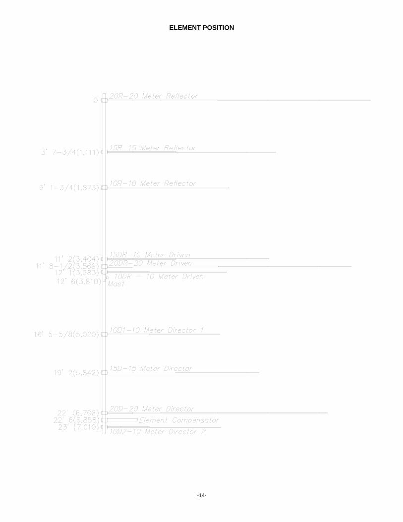
ELEMENT POSITION
-14-

LIMITED WARRANTY
-15-
Bencher, Inc. warrants on the terms hereof, to a Customer who has purchased a Product from a Seller, fora period of one year from the date of the purchase, that the Product was not Defective, but this warranty isvoid if the Product has been subjected to improper or abnormal installation or usage, or a serial number onthe Product has been defaced or removed.
If a Customer believes that a Product is Defective, the customer may, within such one-year period, returnthe entire product to Bencher, Inc. at Bencher's factory, all shipping charges pre-paid by the Customer. Ifthe Product was Defective, Bencher, Inc. will at its option and expense repair or replace the Product andwill at its expense return the repaired or replaced Product to the customer, in a manner selected byBencher, Inc., at the address from which the Customer sent the Product to Bencher, Inc..
THE ABOVE WARRANTY AND REMEDY ARE EXCLUSIVE AND ARE IN LIEU OF ALL OTHERWARRANTIES, EXPRESS OR IMPLIED, INCLUDING BUT NOT LIMITED TO IMPLIED WARRANTIESOF MERCHANTABILITY AND FITNESS FOR A PARTICULAR PURPOSE.
NO SELLER WILL BE LIABLE FOR ANY LOSS, INCONVENIENCE OR DAMAGE, INCLUDING DIRECT,SPECIAL, INCIDENTAL OR CONSEQUENTIAL DAMAGES RESULTING FROM THE USE OF ORINABILITY TO USE A PRODUCT, WHETHER THE LIABILITY WOULD RESULT FROM BREACH OFWARRANTY OR UNDER ANY OTHER LEGAL THEORY.
For instance, this warranty does not cover damage to or caused by an antenna (a) by reason of theantenna acting as a lighting rod, (b) by reason of corrosion or strain from exposure of an antenna to windor weather, (c) from improper assembly, installation or use of an antenna, or (d) from failure periodically toinspect and maintain an antenna and its installation. The Customer is responsible to insure thatinstallation and use of an antenna complies with applicable laws (such as zoning laws) and regulations(such as condominium regulations).
SOME LAWS DO NOT ALLOW THE EXCLUSION OF IMPLIED WARRANTIES, AND IF THESE LAWSAPPLY, THEN ALL EXPRESS AND IMPLIED WARRANTIES ARE LIMITED IN DURATION TO SUCHONE-YEAR PERIOD. NO WARRANTIES OF ANY KIND APPLY AFTER THAT PERIOD.
Such repair or replacement is the Customer's sole and exclusive remedy for a Defective Product. Specifically, Bencher, Inc. is not liable (to the Customer or otherwise) for (a) any loss or damage arising inany way from a Product or from actual or anticipated sale, lease, license or use of a Product, or involvingany matter such as interruption of service, loss of business or anticipated profits, or delay in receiving,repairing, replacing or returning a Product, or (b) any incidental, indirect, special or consequentialdamages.
No other person (such as an employee, agent or dealer) is authorized to change this warranty in any way,or to give any other warranties of any kind on behalf of Bencher, Inc.. This warranty gives a Customerspecific legal rights, and a Customer may also have other rights, which vary from state to state.
As used herein the Customer is the initial end-use purchaser of a Product from a Seller, a Product is anantenna or accessory therefor manufactured by Bencher, Inc., a Product is Defective if and only if theProduct was not free of defects of material and workmanship when manufactured, and a Seller is Bencher,Inc. and any authorized Bencher, Inc. dealer.

-16-

NOTE: All dimensions are ±1/4(6)Element section dimensions are reference onlyDimensions are in inches(millimeters) unless otherwise noted
ELEMENT ASSEMBLY

NOTE: All dimensions are ±1/4(6)Element section dimensions are reference onlyDimensions are in inches(millimeters) unless otherwise noted
BOOM AND ELEMENT TO BOOM ASSEMBLY