order d01 - denartcc.org · o ar may assign apa arrivals via the skarf and puffr stars “descend...
TRANSCRIPT

TOC
Order
D01
TERMINAL RADAR APPROACH CONTROL
December 5, 2016
VATSIM
D01 7110.65A

TOC
Effective Date:
Denver TRACON December 5, 2016
Northwest Mountain District
VATUSA
Subject: D01 Air Traffic Control____________________________________
1. Purpose. Transmits new D01 Order 7110.65A
2. Audience. D01 personnel
3. WHERE TO FIND THIS ORDER? This Order is available in the Denver ARTCC
Document center located here
4. EFFECTIVE DATE. 12/5/2016
5. DISPOSITION OF TRANSMITTAL. Retain this transmittal until superseded by a
new basic order
Marcus Miller
Air Traffic Manager
ZDV ARTCC
Tyler Beals
Deputy Air Traffic Manager
ZDV ARTCC
Tony Jeppesen
Air Traffic Director
VATUSA Western Region
D01 7110.65A

TOC
TABLE OF CONTENTS
SECTORIZATION AND FREQUENCIES ......................................................................................................... 5
COMBINING POSITIONS ................................................................................................................................... 5 Figure 21: Position Decombining Flow .......................................................................................................... 6
DEFINITIONS ........................................................................................................................................................ 6
TRIPS BAR ........................................................................................................................................................... 6 DUALS BAR ........................................................................................................................................................ 6 STANDARDIZED COORDINATION ................................................................................................................. 6 FINAL RADAR PREARRANGED COORDINATION (PACP) AREAS .......................................................... 6 MEAN SEA LEVEL (MSL) ALTITUDES ........................................................................................................... 6
AIRSPACE .............................................................................................................................................................. 6
D01 TRACON AIRSPACE ........................................................................................................................... 6 VFR AIRSPACE/ALTITUDES ..................................................................................................................... 6 ADJACENT TERMINAL AREAS ................................................................................................................ 7 BKF AFB SANDBOX ................................................................................................................................... 7
GENERAL CONTROLLER REQUIREMENTS ................................................................................................ 7
ARRIVAL RADAR (AR1, AR2, AR3, AR4) ........................................................................................................ 7
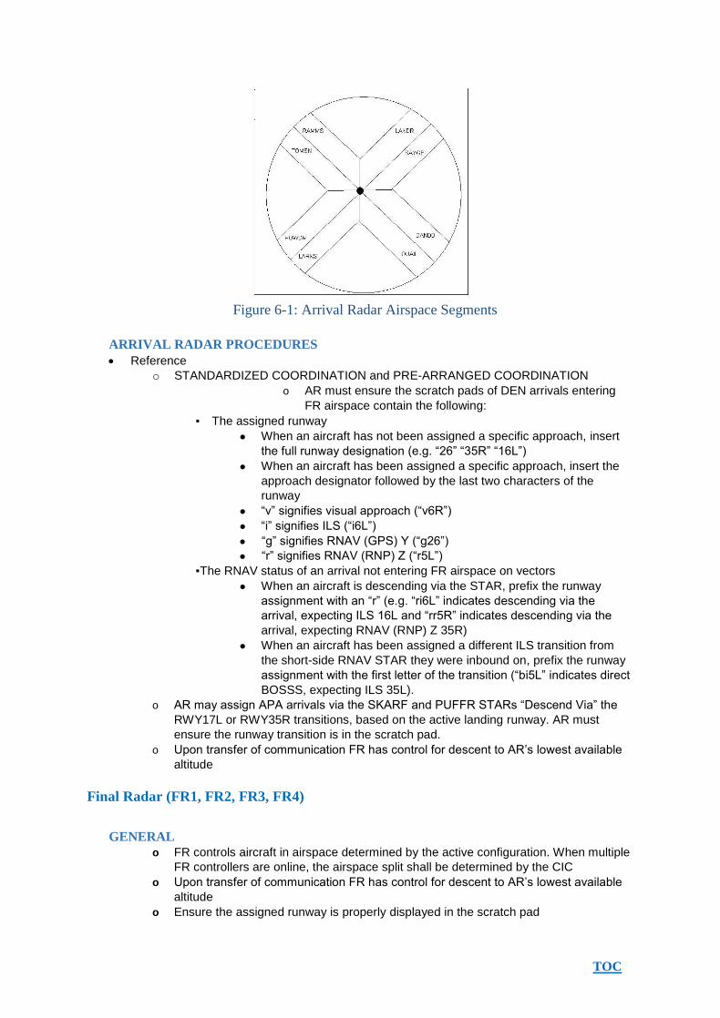
ARRIVAL RADAR AIRSPACE SEGMENTS ..................................................................................................... 7 Figure 61: Arrival Radar Airspace Segments .................................................................................................. 8
ARRIVAL RADAR PROCEDURES .................................................................................................................... 8
FINAL RADAR (FR1, FR2, FR3, FR4) ................................................................................................................ 8
GENERAL ............................................................................................................................................................ 8 AIRSPACE ........................................................................................................................................................... 9
Figure 71: Final Radar Land South Airspace .................................................................................................. 9 Figure 72: Final Radar Land North Airspace ................................................................................................ 10 Figure 73: Final Radar Land East and Land West Airspaces ........................................................................ 10
DUAL & TRIPLE VISUAL/INSTRUMENT APPROACHES ........................................................................... 11 DUAL ILS/RNAV LAND NORTH ............................................................................................................. 11
Figures 74 through 76: Duals North Intercept Fixes and Altitudes .............................................................. 11 DUAL ILS/RNAV LAND SOUTH ............................................................................................................. 11
Figures 77 through 79: Duals South Intercept Fixes and Altitudes .............................................................. 12 DUAL ILS/RNAV LAND WEST ................................................................................................................ 12 DUAL ILS/RNAV LAND EAST ................................................................................................................. 12 TRIPLE ILS/RNAV LAND NORTH........................................................................................................... 12
Figures 710 and 711: Trips North Intercept Fixes and Altitudes ................................................................. 12 Figures 712 and 713: Trips South Intercept Fixes and Altitudes .................................................................. 13
DEPARTURE RADAR (DR1, DR2, DR3, DR4) ................................................................................................ 13
FRONT RANGE AIRPORT (FTG) .................................................................................................................... 13 BUCKLEY AFB (BKF) ...................................................................................................................................... 13
SATELLITE RADAR (SR1, SR2, SR 4) ............................................................................................................. 13
STANDARDIZED COORDINATION ............................................................................................................... 14
HANDOFFS ........................................................................................................................................................ 14 POINT OUTS ...................................................................................................................................................... 14
PREARRANGED COORDINATION PROCEDURES................................................................................... 15
GRAND JUNCTION (JR1) ................................................................................................................................. 16
AIRSPACE .................................................................................................................................................. 16

TOC
JR1 RESPONSIBILITIES............................................................................................................................ 16 Figure 121: Grand Junction Airspace 14,000 to Surface............................................................................... 16
PUEBLO (PR1) ..................................................................................................................................................... 17
AIRSPACE .................................................................................................................................................. 17 PR1 RESPONSIBILITIES ........................................................................................................................... 17
Figure 131 Pueblo airspace 12,000 to surface .............................................................................................. 17
APPENDIX ............................................................................................................................................................ 18
APPENDIX 1: AR, DR, SR AIRSPACE LAND SOUTH ................................................................................... 18 Diagram 11: AR Airspace Land South ........................................................................................................... 18 Diagram 13: SR Airspace Land South ........................................................................................................... 20
APPENDIX 2: AR, DR, SR AIRSPACE LAND NORTH ................................................................................... 21 Diagram 23: SR Airspace Land North ........................................................................................................... 23
APPENDIX 3: AR, DR, SR AIRSPACE LAND SOUTH WEST........................................................................ 24 Diagram 33: SR Airspace Land South West ................................................................................................... 26
APPENDIX 4: AR, DR, SR AIRSPACE LAND NORTH WEST ....................................................................... 27 Diagram 43: SR Airspace Land North West................................................................................................... 29
APPENDIX 5: AR, DR, SR AIRSPACE LAND SOUTH EAST ........................................................................ 30 Diagram 53: SR Airspace Land South East ................................................................................................... 32
APPENDIX 6: AR, DR, SR AIRSPACE LAND NORTH EAST ........................................................................ 33 Diagram 62: DR Airspace Land North East .................................................................................................. 34 Diagram 63: SR Airspace Land North East ................................................................................................... 35
APPENDIX 7: AR, DR, SR AIRSPACE LAND WEST...................................................................................... 36 Diagram 73: SR Airspace Land West ............................................................................................................. 38
APPENDIX 8: AR, DR, SR AIRSPACE LAND EAST ...................................................................................... 39 Diagram 83: SR Airspace Land East ............................................................................................................. 41
APPENDIX 9: AR, DR, SR AIRSPACE LAND NORTH SOUTH ..................................................................... 42 Diagram 93: SR Airspace Land North South. ................................................................................................ 44
TOC
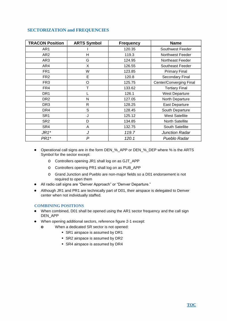
SECTORIZATION and FREQUENCIES
TRACON Position ARTS Symbol Frequency Name
AR1 I 120.35 Southwest Feeder
AR2 H 119.3 Northwest Feeder
AR3 G 124.95 Northeast Feeder
AR4 X 126.55 Southeast Feeder
FR1 W 123.85 Primary Final
FR2 E 120.8 Secondary Final
FR3 O 125.75 Center/Converging Final
FR4 T 133.62 Tertiary Final
DR1 L 126.1 West Departure
DR2 N 127.05 North Departure
DR3 R 128.25 East Departure
DR4 S 128.45 South Departure
SR1 J 125.12 West Satellite
SR2 D 134.85 North Satellite
SR4 A 132.75 South Satellite
JR1* J 119.7 Junction Radar
PR1* P 120.1 Pueblo Radar
Operational call signs are in the form DEN_%_APP or DEN_%_DEP where % is the ARTS
Symbol for the sector except:
o Controllers opening JR1 shall log on as GJT_APP
o Controllers opening PR1 shall log on as PUB_APP
o Grand Junction and Pueblo are nonmajor fields so a D01 endorsement is not
required to open them All radio call signs are “Denver Approach” or “Denver Departure.”
Although JR1 and PR1 are technically part of D01, their airspace is delegated to Denver
center when not individually staffed.
COMBINING POSITIONS
When combined, D01 shall be opened using the AR1 sector frequency and the call sign
DEN_APP
When opening additional sectors, reference figure 21 except:
o When a dedicated SR sector is not opened:
SR1 airspace is assumed by DR1
SR2 airspace is assumed by DR2
SR4 airspace is assumed by DR4

TOC
Figure 21: Position Decombining Flow
DEFINITIONS
TRIPS BAR
o The line on the D01 land north video map that denotes BOOBU, CRUUP, DORRY
and KALHR intersections. The line on the D01 land south video map that denotes
JOBOB, HOOPE, GWENS and SAKIC intersections.
DUALS BAR
o The line on the D01 land north video map that denotes BENGL, CHOLA, DEANN and
MARKL intersections. The line on the D01 land east video map that denotes SARAH
and LIPPS intersections. The line on the D01 land west video map that denotes
FUZZZ and ETHAL intersections
STANDARDIZED COORDINATION
o Specific situations that, if the procedures listed are performed, eliminate the
requirement of the controller initiating handoff or point out to transfer heading, altitude
and/or speed information to the receiving controller.
FINAL RADAR PREARRANGED COORDINATION (PACP) AREAS
o In the Land North and Land South FR airspace, the Short Side RNAV STARs are
contained within PACP Areas named after the associated STAR. These areas are
delegated to specific FR positions based on the operations being conducted.
MEAN SEA LEVEL (MSL) ALTITUDES
o Unless otherwise stated, all procedural altitudes are listed as MSL.
AIRSPACE
D01 TRACON AIRSPACE: Flight Level 230 and below within the lateral boundaries of the
TRACON. Airspace is further divided into specific positions of operation.
VFR AIRSPACE/ALTITUDES: In all Denver TRACON airspace assignments, the
overlying sector owns

TOC
500’ below their designated airspace for use by Visual Flight Rules (VFR) aircraft only.
ADJACENT TERMINAL AREAS: Colorado Springs Terminal Area airspace and
Cheyenne Terminal Area airspace.
BKF AFB SANDBOX: An area described in the D01DEN ATCT LOA, established for
operations (VFR Climb and Descent) into and out of BKF AFB.
GENERAL CONTROLLER REQUIREMENTS
All radar positions shall maintain 1.5 miles separation from other sectors and from Minimum Vectoring
Altitudes
(MVA) lines. Maintain 2.5 miles separation between all sectors when greater than 40 DME from
KDEN.
All D01 controllers are assigned squawk range 06010677.
All D01 controllers shall comply with the provisions of the D01 and DEN ATCT, FTG ATCT, APA
ATCT, BJC ATCT, GJT ATCT, PUB ATCT, COS TRACON, CYS RAPCON and ZDV ARTCC letters
of agreement as required by the position staffed.
All radar controllers shall display the following at all times:
D01 PRIMARY video map
D01 MVA video map
NORTH, SOUTH, EAST, and/or WEST video maps based on the current arrival configuration
5 mile range rings centered around KDEN (located at the radar site)
Four letter scratchpads. In VRC this requires the use of the ARTS or DSR radar mode. In
vSTARS this requires a setting in facility management.
ARRIVAL RADAR (AR1, AR2, AR3, AR4)
ARRIVAL RADAR AIRSPACE SEGMENTS
AR airspace is based on eight segments. The EastWest airspace dividing line is the
extended centerline of Runway 17R/35L. The NorthSouth airspace dividing line is the
extended centerline of Runway 8/26.
Each segment is based on one of the legacy Standard Terminal Arrival Routes. Specific
airspace, altitude assignments and traffic flows are depicted and assigned in Appendices 19.
AR1 is assigned segments POWDR and LARKS
AR2 is assigned segments RAMMS and TOMSN
AR3 is assigned segments LANDR and SAYGE
AR4 is assigned segments DANDD and QUAIL
Unless otherwise specified by the ATM, DATM, TA, EC or CIC, AR3 is normally
combined with AR2 and AR4 is normally combined with AR1.
TOC
Figure 61: Arrival Radar Airspace Segments
ARRIVAL RADAR PROCEDURES
Reference
o STANDARDIZED COORDINATION and PREARRANGED COORDINATION
o AR must ensure the scratch pads of DEN arrivals entering
FR airspace contain the following:
The assigned runway
When an aircraft has not been assigned a specific approach, insert
the full runway designation (e.g. “26” “35R” “16L”)
When an aircraft has been assigned a specific approach, insert the
approach designator followed by the last two characters of the
runway
“v” signifies visual approach (“v6R”)
“i” signifies ILS (“i6L”)
“g” signifies RNAV (GPS) Y (“g26”)
“r” signifies RNAV (RNP) Z (“r5L”)
The RNAV status of an arrival not entering FR airspace on vectors
When an aircraft is descending via the STAR, prefix the runway
assignment with an “r” (e.g. “ri6L” indicates descending via the
arrival, expecting ILS 16L and “rr5R” indicates descending via the
arrival, expecting RNAV (RNP) Z 35R)
When an aircraft has been assigned a different ILS transition from
the shortside RNAV STAR they were inbound on, prefix the runway
assignment with the first letter of the transition (“bi5L” indicates direct
BOSSS, expecting ILS 35L).
o AR may assign APA arrivals via the SKARF and PUFFR STARs “Descend Via” the
RWY17L or RWY35R transitions, based on the active landing runway. AR must
ensure the runway transition is in the scratch pad.
o Upon transfer of communication FR has control for descent to AR’s lowest available
altitude
Final Radar (FR1, FR2, FR3, FR4)
GENERAL
o FR controls aircraft in airspace determined by the active configuration. When multiple
FR controllers are online, the airspace split shall be determined by the CIC
o Upon transfer of communication FR has control for descent to AR’s lowest available
altitude
o Ensure the assigned runway is properly displayed in the scratch pad

TOC
o Provide standard IFR separation to VFR aircraft conducting practice instrument
approaches to KDEN
AIRSPACE
o Land South designated airspace and PACP areas:
Figure 71: Final Radar Land South Airspace
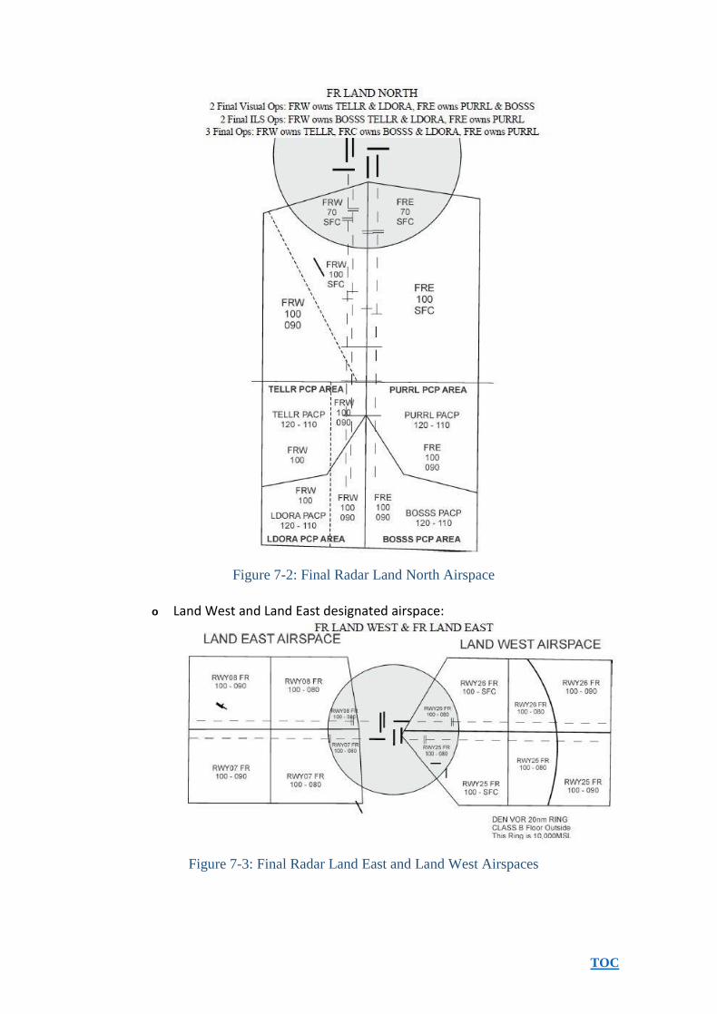
o Land North designated airspace and PACP areas:
TOC
Figure 72: Final Radar Land North Airspace
o Land West and Land East designated airspace:
Figure 73: Final Radar Land East and Land West Airspaces

TOC
DUAL & TRIPLE VISUAL/INSTRUMENT APPROACHES
o DUAL VISUALS (VV): FRE & FRW remain 3nm from adjacent final approach course
in use, until visual approach clearance is issued and acknowledged, unless another
form of separation is provided
o ONE VISUAL & ONE INSTRUMENT (VI): One FR issues ILS/RNAV approach
clearance and ensures aircraft is established on an approach segment, or on a 30
degree intercept heading to join the final approach course, prior to 3nm from the
adjacent final approach course in use. The other remains 3nm form adjacent final
approach course in use, until visual approach clearance is issued and acknowledged,
unless another form of separation is provided.
o TRIPLES (VISUAL OUTBOARDS & INSTRUMENT CENTER (VIV)): FRE & FRW
remain 3nm from adjacent final approach course in use, until visual approach
clearance is issued and acknowledged, unless another form of separation is
provided. FRC must not exit their airspace until the aircraft is established on final and
an approach clearance is issued, unless another form of separation is provided.
DUAL ILS/RNAV LAND NORTH: Approaches may be conducted in conjunction with
visual or instrument approaches to converging runways in accordance with the Denver
ATCT/D01 LOA. To ensure procedural separation aircraft must be established on the localizer
by the fixes and altitudes depicted. Nonstandard fixes/altitudes must be coordinated when
FR is split.
Figures 74 through 76: Duals North Intercept Fixes and Altitudes
DUAL ILS/RNAV LAND SOUTH: Approaches may be conducted in conjunction with
visual or instrument approaches to converging runways in accordance with the Denver
ATCT/D01 LOA. To ensure procedural separation aircraft must be established on the localizer
by the fixes and altitudes depicted. Nonstandard fixes/altitudes must be coordinated when
FR is split.

TOC
Figures 77 through 79: Duals South Intercept Fixes and Altitudes
DUAL ILS/RNAV LAND WEST: To ensure procedural separation:
o FR working RWY26 must cross 3nm outside of FUZZZ at 9000
o FR working RWY25 must cross ETHAL at 10000
DUAL ILS/RNAV LAND EAST: To ensure procedural separation:
o FR working RWY08 must cross LIPPS at 10000
o FR working RWY07 must cross 3nm outside of SARAH at 9000
TRIPLE ILS/RNAV LAND NORTH: To ensure procedural separation aircraft must be
established on the localizer by the fixes and altitudes depicted. Nonstandard fixes/altitudes
must be coordinated when FR
is split.
Figures 710 and 711: Trips North Intercept Fixes and Altitudes TRIPLE ILS/RNAV LAND SOUTH: To ensure procedural separation aircraft must be
established on the localizer by the fixes and altitudes depicted. Nonstandard fixes/altitudes
must be coordinated when FR is split.
TOC
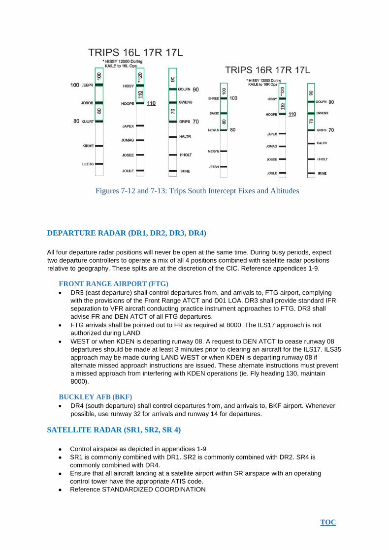
Figures 712 and 713: Trips South Intercept Fixes and Altitudes
DEPARTURE RADAR (DR1, DR2, DR3, DR4)
All four departure radar positions will never be open at the same time. During busy periods, expect
two departure controllers to operate a mix of all 4 positions combined with satellite radar positions
relative to geography. These splits are at the discretion of the CIC. Reference appendices 19.
FRONT RANGE AIRPORT (FTG)
DR3 (east departure) shall control departures from, and arrivals to, FTG airport, complying
with the provisions of the Front Range ATCT and D01 LOA. DR3 shall provide standard IFR
separation to VFR aircraft conducting practice instrument approaches to FTG. DR3 shall
advise FR and DEN ATCT of all FTG departures.
FTG arrivals shall be pointed out to FR as required at 8000. The ILS17 approach is not
authorized during LAND
WEST or when KDEN is departing runway 08. A request to DEN ATCT to cease runway 08
departures should be made at least 3 minutes prior to clearing an aircraft for the ILS17. ILS35
approach may be made during LAND WEST or when KDEN is departing runway 08 if
alternate missed approach instructions are issued. These alternate instructions must prevent
a missed approach from interfering with KDEN operations (ie. Fly heading 130, maintain
8000).
BUCKLEY AFB (BKF)
DR4 (south departure) shall control departures from, and arrivals to, BKF airport. Whenever
possible, use runway 32 for arrivals and runway 14 for departures.
SATELLITE RADAR (SR1, SR2, SR 4)
Control airspace as depicted in appendices 19
SR1 is commonly combined with DR1. SR2 is commonly combined with DR2. SR4 is
commonly combined with DR4.
Ensure that all aircraft landing at a satellite airport within SR airspace with an operating
control tower have the appropriate ATIS code.
Reference STANDARDIZED COORDINATION

TOC
STANDARDIZED COORDINATION
HANDOFFS: Heading, Speed, and Altitude information does not need to be transferred between
radar positions when accomplishing a handoff in the following situations:
All D01 radar positions must handoff aircraft to the FR1, FR2, FR3 and FR4 positions as
follows:
o At least 10 NM prior to the FR lateral airspace boundary.
o Transfer communications as soon as possible after FR has accepted the handoff
(preferably no later than 5nm from the lateral boundary).
o Prior to transferring communications to FR;
Base Legs: Established on a heading that will maintain a track perpendicular
to the final approach course, plus or minus 20 degrees, established on an
RNAV STAR, or direct the IAF of a Runway Transition.
Downwinds: Established on a track parallel to the final approach course or
established on an RNAV STAR.
StraightIns: Established on, or on a vector to join, a final approach course.
o Ensure DEN arrival aircraft are at or descending to the lowest altitude owned by the
AR position at the time of the flash and assigned a speed of 210 knots or less prior to
transferring communication. Note: Aircraft “Descending Via” an RNAV STAR satisfy this
requirement
AR may handoff satellite airport arrival aircraft to DR “Descending Via” an RNAV
STAR/Runway
Transition, or descending to maintain the lowest altitude available to the AR position, based
on MVA and assigned airspace, at an assigned airspeed of 250 knots or less.
DR and SR positions may handoff satellite airport arrival aircraft to the SR positions:
o “Descending Via” an RNAV STAR/Runway Transition.
o Established on a heading that will maintain a track within 20 degrees of direct to the
satellite arrival airport or perpendicular to the final approach course, plus or minus 20
degrees.
o Aircraft on a downwind must be on a track parallel to the final approach course.
o Aircraft not “Descending Via” an RNAV STAR/Runway Transition must be
descending to the lowest altitude available to the radar position initiating the handoff,
based on MVAs and airspace and assigned a speed of 210 knots or less.
SR4 may handoff an aircraft departing Centennial Airport filed out the west, north or east
departure gate to DR1 established on a 320 degree heading, climbing to 8,000 MSL.
Any satellite airport departure cleared direct to a SID exit fix located on the Tracon/center
boundary climbing to FL230 or filed lower altitude with no speed assignment.
After receiving a handoff from another D01 position, the receiving controller has control on
contact for 20 degrees turns and climb or descent into their own airspace. FR may exceed 20
degrees of turn when turning toward the airport
POINT OUTS
FR may point out DEN arrivals to any DR position and use simplified phraseology: o
“Point out, [call sign], landing Denver”
o If the DR position says “point out approved,” FR may turn the aircraft towards DEN
airport and descend to the lowest usable altitude.

TOC
PREARRANGED COORDINATION PROCEDURES
DR has control for turns and climb within other DR airspace so long as the aircraft is within
20 miles of KDEN and the turn is in a direction towards the filed departure gate o Each DR
position is responsible for separating their aircraft and all other aircraft preceding theirs.
o This procedure is valid anytime any number of DR positions are open and other FR
and/or AR positions are open
DR may force the data block of a departure onto FR or AR’s scope using the F1 function
and climb their departure through FR and AR airspace without verbalizing a point out. DR is
responsible for missing all traffic. This procedure is only valid if the departure is within DR’s
lateral boundary.
o The departure must be clear of AR and FR airspace prior to the departure entering
ZDV or another DR’s airspace.
TOC
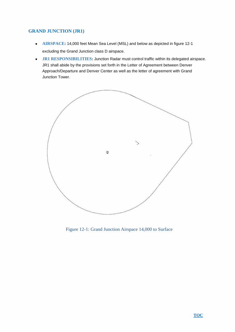
GRAND JUNCTION (JR1)
AIRSPACE: 14,000 feet Mean Sea Level (MSL) and below as depicted in figure 121
excluding the Grand Junction class D airspace.
JR1 RESPONSIBILITIES: Junction Radar must control traffic within its delegated airspace.
JR1 shall abide by the provisions set forth in the Letter of Agreement between Denver
Approach/Departure and Denver Center as well as the letter of agreement with Grand
Junction Tower.
Figure 121: Grand Junction Airspace 14,000 to Surface

TOC
PUEBLO (PR1)
AIRSPACE: 12,000 Mean Sea Level (MSL) and below as depicted in figure 131 excluding
the Pueblo class D airspace.
PR1 RESPONSIBILITIES: Pueblo Radar must control traffic within its delegated airspace.
PR1 shall abide by the provisions set forth in the Letter of Agreement between Denver
Approach/Departure and Denver Center as well as the letter of agreement with Pueblo Tower.
Figure 131 Pueblo airspace 12,000 to surface
TOC
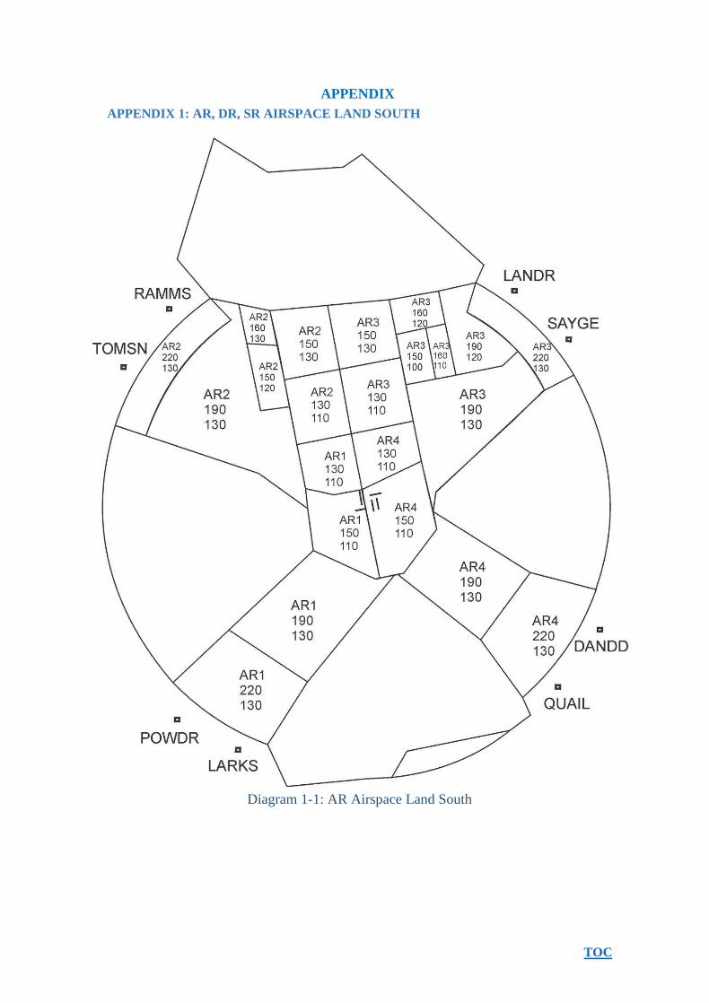
APPENDIX
APPENDIX 1: AR, DR, SR AIRSPACE LAND SOUTH
Diagram 11: AR Airspace Land South

TOC
Diagram 12: DR Airspace Land South

TOC
Diagram 13: SR Airspace Land South

TOC
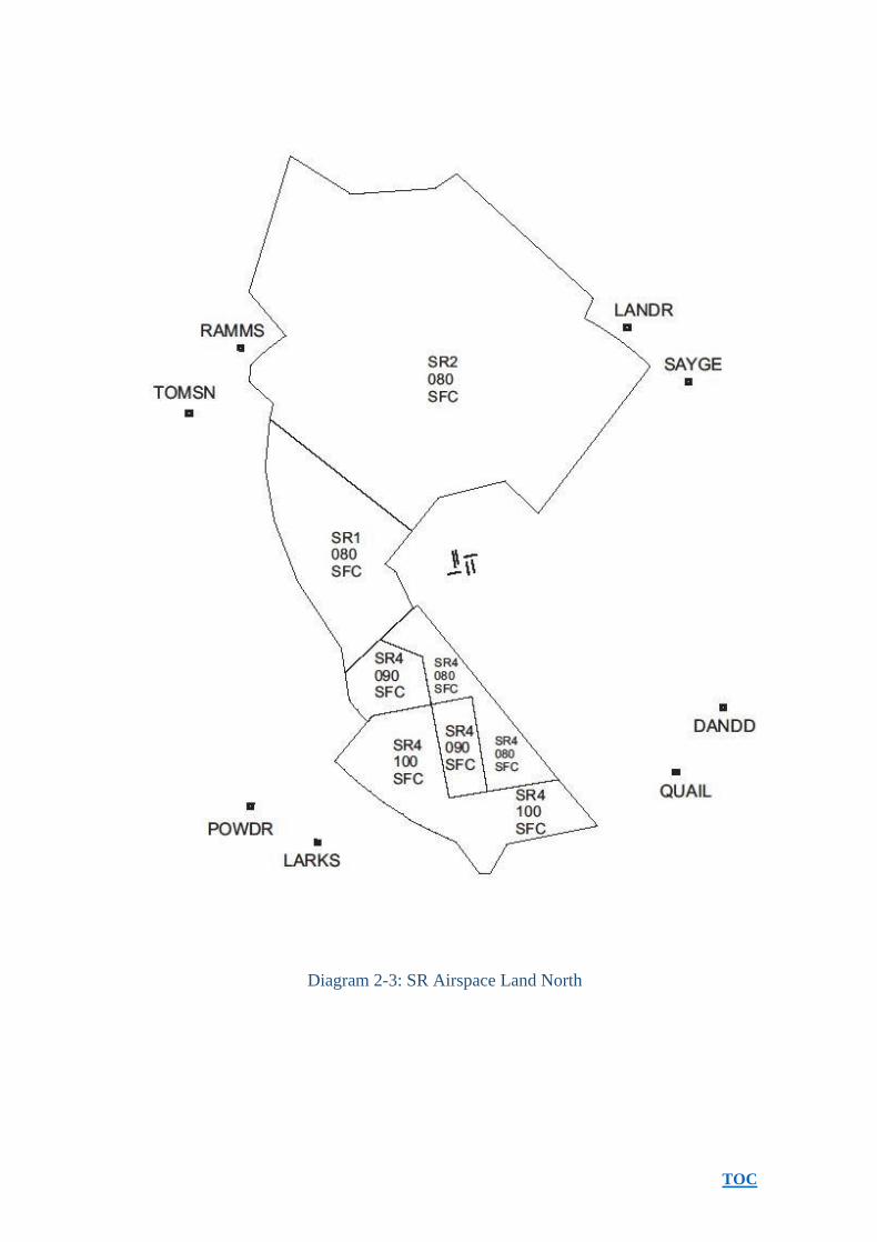
APPENDIX 2: AR, DR, SR AIRSPACE LAND NORTH
Diagram 21: AR Airspace Land North

TOC
Diagram 22: DR Airspace Land North
TOC
Diagram 23: SR Airspace Land North

TOC
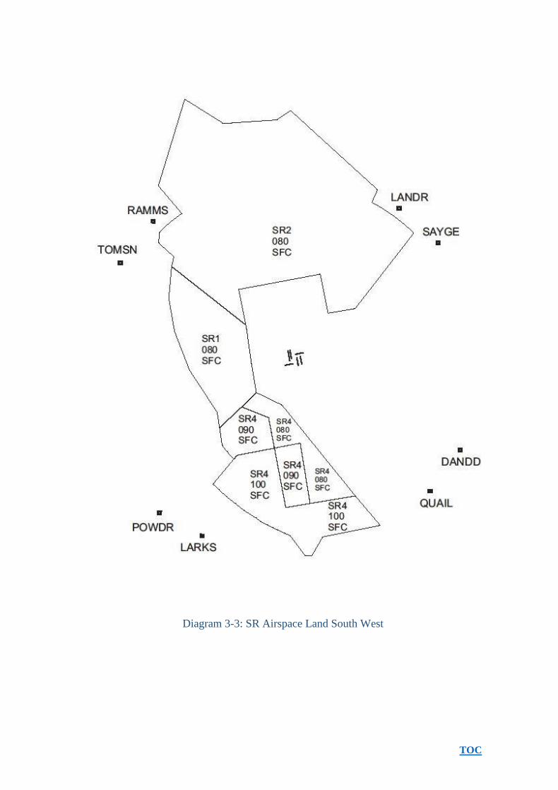
APPENDIX 3: AR, DR, SR AIRSPACE LAND SOUTH WEST
Diagram 31: AR Airspace Land South West

TOC
Diagram 32: DR Airspace Land South West
TOC
Diagram 33: SR Airspace Land South West
TOC
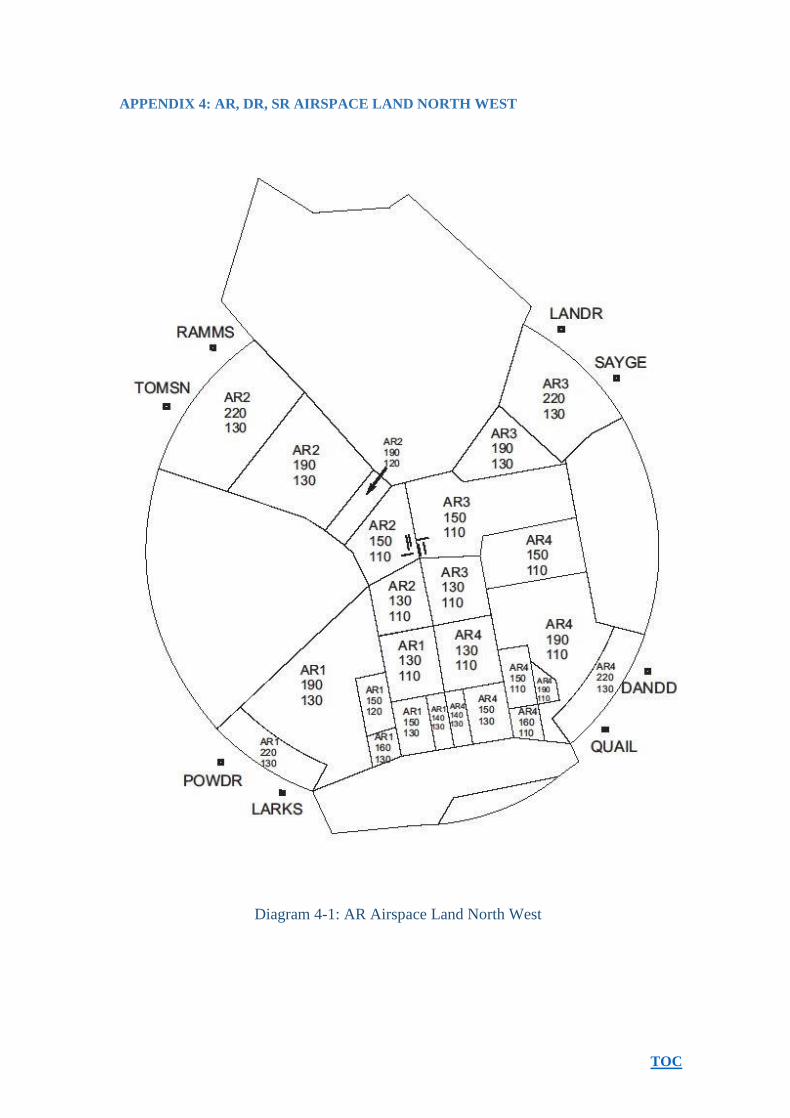
APPENDIX 4: AR, DR, SR AIRSPACE LAND NORTH WEST
Diagram 41: AR Airspace Land North West

TOC
Diagram 42: DR Airspace Land North West

TOC
Diagram 43: SR Airspace Land North West

TOC
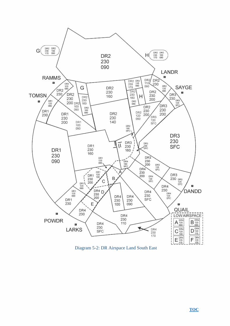
APPENDIX 5: AR, DR, SR AIRSPACE LAND SOUTH EAST
Diagram 51: AR Airspace Land South East
TOC
Diagram 52: DR Airspace Land South East

TOC
Diagram 53: SR Airspace Land South East

TOC
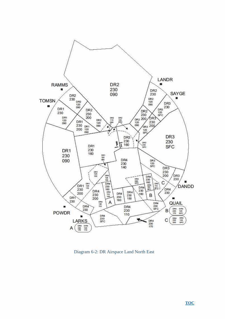
APPENDIX 6: AR, DR, SR AIRSPACE LAND NORTH EAST
Diagram 61: AR Airspace Land North East
TOC
Diagram 62: DR Airspace Land North East

TOC
Diagram 63: SR Airspace Land North East

TOC
APPENDIX 7: AR, DR, SR AIRSPACE LAND WEST
Diagram 71: AR Airspace Land West

TOC
Figure 72: DR Airspace Land West

TOC
Diagram 73: SR Airspace Land West

TOC
APPENDIX 8: AR, DR, SR AIRSPACE LAND EAST
Diagram 81: AR Airspace Land East

TOC
Diagram 82: DR Airspace Land East

TOC
Diagram 83: SR Airspace Land East

TOC
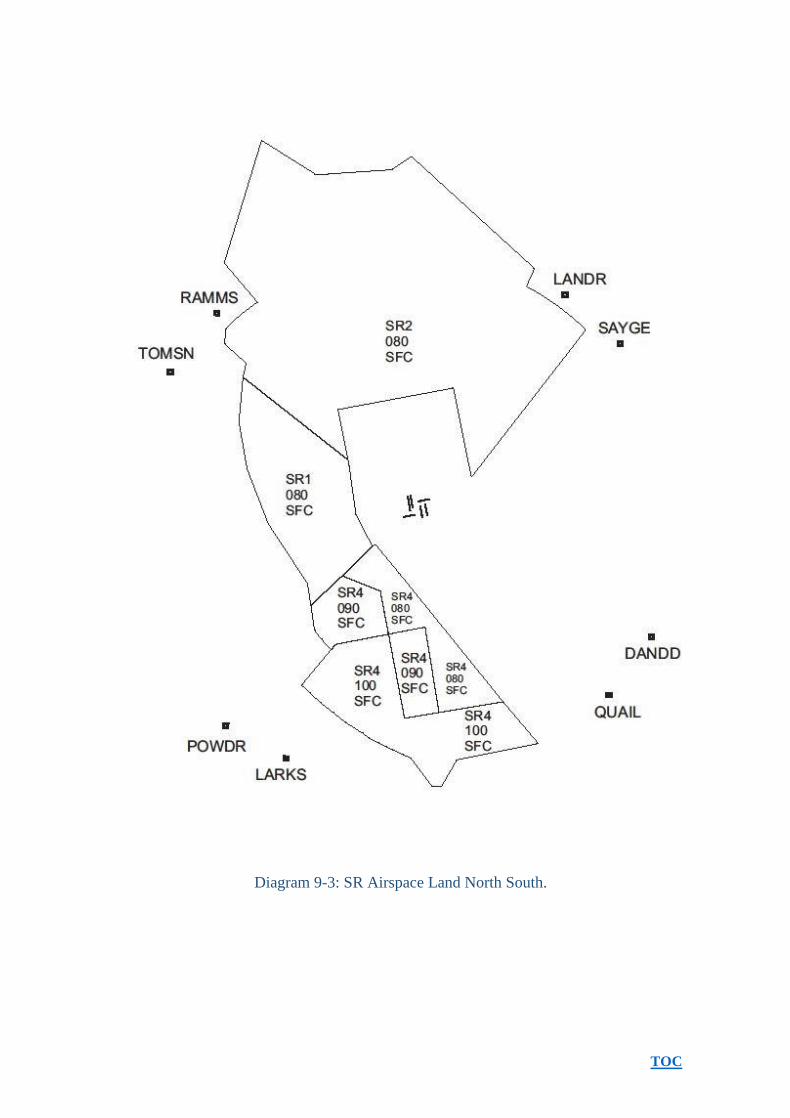
APPENDIX 9: AR, DR, SR AIRSPACE LAND NORTH SOUTH
Diagram 91: AR Airspace Land North South

TOC
Diagram 92: DR Airspace Land North South
TOC
Diagram 93: SR Airspace Land North South.