orchestration of smart objects with mqtt for the internet...
TRANSCRIPT

University of Padua
DEPARTMENT OF INFORMATION ENGINEERING
Master Degree in Computer Engineering
Master Degree Thesis
Orchestration of smart objects withMQTT for the Internet of Things
Candidate:
Gianmarco NalinID Number: 1033984 - IF
Thesis advisor:
Ch.mo Prof. Carlo Ferrari
Research supervisor:
Ing. Michele Stecca
Academic Year 2013 - 2014


“The only way to do great work is to love what you do.”Steve Jobs
To Elena, the strongest woman I have ever met.


Abstract
At the beginning of Internet, users were only consumers of information, in whatit is called Web 1.0. Thanks to the integration with databases and contentmanagement systems (CMS), the way users interact with the Web has changed.People can become also creator of contents and, therefore, contribute to theemerging Web 2.0.
In this scenario, many companies make available several web services to in-teract with, permitting users and developers to create custom applications.
At the same time, devices permit users to remain connected everywhere andanytime. Not only smartphones, tablets and PCs but also fridges, washingmachines and cars. These new connected devices can exchange information withthe real world in order to remotely act with them. This is the Internet ofThings (IoT), where objects and services coexist e cooperate.
The IoT is evolving as fast as companies and developers identify new oppor-tunities of growth. This growth is possible if there exist protocols which enableinteroperability between different devices and networks. In this direction, IBMhas developed MQTT, a new protocol which facilitates devices integration andmanagement in constrained environment.
In this thesis, we will describe a platform which permits the creation ofcomposite services (a.k.a. mashups) that combine several web services andphysical devices to execute custom tasks.
In Chapter 1, we will introduce the Internet of Things describing some nowa-days architectures. In Chapter 2 we will give a short description of the iCoreproject, which is the work’s starting point. In Chapter 3, we will describe thepublish/subscribe paradigm as well as the MQTT protocol. In Chapter 4, wewill introduce a creation and execution composite services platform. Finally, wewill state results and future developments about the project.


Contents
1 An introduction to the Internet of Things 11.1 Semantic meaning of Internet of Things . . . . . . . . . . . . . . 11.2 Main Challenges for the IoT . . . . . . . . . . . . . . . . . . . . . 21.3 Constrained Application Protocol and Machine to Machine Com-
munications . . . . . . . . . . . . . . . . . . . . . . . . . . . . . . 21.4 IoT applications . . . . . . . . . . . . . . . . . . . . . . . . . . . 31.5 The Web of Things . . . . . . . . . . . . . . . . . . . . . . . . . . 4
1.5.1 RESTful Architectures . . . . . . . . . . . . . . . . . . . . 51.6 Case study: Xively R© . . . . . . . . . . . . . . . . . . . . . . . . . 7
1.6.1 How it works . . . . . . . . . . . . . . . . . . . . . . . . . 91.6.2 Pricing . . . . . . . . . . . . . . . . . . . . . . . . . . . . 11
2 The iCore Project 132.1 Service Creation Platform . . . . . . . . . . . . . . . . . . . . . . 132.2 Service Execution Platform . . . . . . . . . . . . . . . . . . . . . 14
2.2.1 Service Proxy . . . . . . . . . . . . . . . . . . . . . . . . . 152.2.2 Orchestrator . . . . . . . . . . . . . . . . . . . . . . . . . 15
3 A publish-subscribe protocol: MQTT 193.1 Publish-Subscribe Systems . . . . . . . . . . . . . . . . . . . . . . 20
3.1.1 The programming model . . . . . . . . . . . . . . . . . . . 213.2 Message Queue Telemetry Transport . . . . . . . . . . . . . . . . 22
3.2.1 Message format . . . . . . . . . . . . . . . . . . . . . . . . 233.2.2 Message flows . . . . . . . . . . . . . . . . . . . . . . . . . 253.2.3 MQTT Applications . . . . . . . . . . . . . . . . . . . . . 27
3.3 An MQTT implementation: Paho . . . . . . . . . . . . . . . . . . 293.4 Terracotta R© Universal Messaging: setting up a local environment 29
3.4.1 Terracotta Universal Messaging . . . . . . . . . . . . . . . 303.4.2 Client Implementation with Paho MQTT . . . . . . . . . 34
4 Integrating MQTT into the platform 374.1 Centralized SEP . . . . . . . . . . . . . . . . . . . . . . . . . . . 38
4.1.1 Example . . . . . . . . . . . . . . . . . . . . . . . . . . . . 384.2 Distributed SEP . . . . . . . . . . . . . . . . . . . . . . . . . . . 44
4.2.1 Example . . . . . . . . . . . . . . . . . . . . . . . . . . . . 454.3 Centralized and distributed implementation comparison . . . . . 51
Conclusion and future developments 53

A Publisher Java Code 55
B Subscriber Java Code 57
Bibliography 59

Chapter 1
An introduction to theInternet of Things
Nowadays, we have the ability to measure, sense and monitor everything inthe physical world. How can we use these information to increase businessproductivity, improve human health and monitor environment situation? Canwe make them publicly available in order to enhance the knowledge? A Ciscostudy [12] states that in 2020 there will be about 50 billion of connected physicalworld devices, fueled by a 1000× increase in wireless broadband traffic. This isa huge number of devices and their interoperability is a challenge these days: weneed protocols that make possible the communication between all these devices.
In the following sections, we will present an overview about what we intendwith Internet of Things (IoT) using practical examples followed by a case studyof a company whose core business is founded on IoT.
1.1 Semantic meaning of Internet of Things
Huang and Li in [2] analyze the semantic meaning of Internet of things: generally,the nouns in phrase like “noun1 + of + noun2” are related in some way andhave an affiliation relation or an apposition relation. With the phrase Internetof things, we have an exception: the relationship between the two nouns is notthe one described above but a more exact understanding is “the Internet relatedto things”.
The main function of Internet is to interconnect, using cables, optical fiber ormicrowaves, the computer terminals all around the world. The objects transmit-ted in form of electric or optical signals cannot be things as material entities butonly the information as immaterial ones. So, the semantic meaning of Internetof things is the “Internet relating to information of things”, where with the term“relating to” we intend that the information produced by things flows rationallyon the Internet in order to be shared all around the world.
1

CHAPTER 1. AN INTRODUCTION TO THE INTERNET OF THINGS 2
1.2 Main Challenges for the IoT
There are several challenges to which the IoT vision should overcome: contextual(including policy) and technical applications are the main ones. In a world whereeverything is interconnected, where data about local environment (and abouthumans in direct or indirect way) are exchanged, privacy is fundamental andit has to be guaranteed and protected. The individual’s trust to the IoT shouldbe complete and information about negative impact on individual or society hasto be safeguarded.
Standardization of technologies is also important because it will lead tobetter interoperability with a reduction of the entry barriers. Nowadays, eachmanufacturer produces and implements its own solution based on vertical in-tegration of the entire system. The change from Intranet of Things to a morecomplete Internet of Things is a fundamental requirement.
So, the key challenges areas are:
• Privacy, identity management, security and access control: whocan share and see with which credentials is a significant challenge.
• Standardization and interoperability: how can we guarantee that allthe technology platforms continue to act, as a unique and coherent plat-form, where we do not to re-invent the wheel every time we have to developa new application or we have to add a new sensor to the system?
1.3 Constrained Application Protocol and Ma-chine to Machine Communications
The term machine to machine (M2M) refers to technologies that allow wiredand wireless systems to communicate with other devices of the same type. M2Mdoes not refer to specific network, information and communication technologies.It is particularly useful for business executives.
Modern M2M communication has expanded beyond the one-to-one connec-tion and changed into a systems of networks that transmit data to personalappliances. With the world adoption and expansion of IP networks, M2M com-munication has begun to take place with the reduction of the amount of powerand time necessary for information to be collected and transmitted between ma-chines. A possible protocol that allows M2M communication is the ConstrainedApplication Protocol.
Constrained Application Protocol (CoAP) is an application level (ISO/OSIlevel 7) protocol which is suitable for very small and resource-limited devices.The protocol stack is showed in Figure 1.1. It allows devices to communicate in-teractively over the Internet. CoAP is ideal for small low power sensors, switchesand similar devices which have to be controlled over the standard Internet net-work.
CoAP is designed to be a RESTful protocol that permits both synchronousand asynchronous communication. It is specialized for Machine to Machineand IoT applications and it permits an easy proxying to/from HTTP. The pro-tocol is not designed neither to be a replacement for HTTP nor deeply separatefrom the Web, but to be extremely merge with it.

CHAPTER 1. AN INTRODUCTION TO THE INTERNET OF THINGS 3
Application
CoAP Request/Response
CoAP Messages
UDP
Figure 1.1: CoAP position in the ISO/OSI architecture.
1.4 IoT applications
In this section, we present some of the possible applications of the Internet ofThings. As in [1], we can group everyday situations in several sets, showing howIoT is becoming a technological revolution.
• SMART CITIES
Smart parking Monitoring of parking spaces available in the city;
Smart health Monitoring of health status of buildings, bridges or histor-ical monuments;
Noise urban maps Sound monitoring in central zone in real time
Traffic congestion Monitoring of vehicles and pedestrian levels and op-timize routes;
Waste management Detection of rubbish levels in containers and opti-mize trash collection routes.
• SMART ENVIRONMENT
Forest fire detection Monitoring of combustion gases and fire over crit-ical zones;
Air pollution Monitoring and control of CO2 emissions of factories andfarms.
• RETAIL
Supply chain control Monitoring of stock conditions and product track-ing;
Near Field Communication (NFC) payments Payment processing forpublic transport, gyms, coffee shops, etc.

CHAPTER 1. AN INTRODUCTION TO THE INTERNET OF THINGS 4
• INDUSTRIAL CONTROL
Machine to machine (M2M) applications Machines auto-diagnosticand assets control.
• DOMOTIC AND HOME AUTOMATION
Energy and water use Monitoring and control of water and energy us-age in order to save money and resources;
Remote control appliances Switching on and off remotely appliancesin order to avoid accidents.
• EHEALTH
Patients surveillance Monitoring and control patience condition in hishospital room or in his own home;
Fall detection Assistance for older or disable people to make them livingindependent.
1.5 The Web of Things
The creation of smart things and their interconnection through a network hasbecome a goal of many reasearch activities. Rather than creating a brand newvertical architecture specific for this purpose, it has been proposed to make theseobjects an integral part of the Web.
In this scenario, popular Web technologies such as HTML, JavaScript,Ajax, PHP, ASP.NET, can be used to build applications that involve smartthings and users can leverage weel-known Web mechanisms, e.g. browsing,searching, bookmarking, linking, to interact with and share these devices.
A first proposal came in [5] by Kindberg et al.: they proposed to link physicalobjects with Web pages which contain information and services. By the useof infrared reader or bar codes on objects, users can retrieve the URI of theassociated page with a simple interaction paradigm.
Another interaction model has been provided in [6] by Guinard et al. inwhich they propose to incorporate real world smart objects into a standardizedWeb service architecture, e.g. using SOAP (Simple Object Access Protocol),WSDL (Web Services Description Language), UDDI (Universal DescriptionDiscovery and Integration). In practice, such integration method is too heavyand complex for objects with limited resources.
Recently, several ”Web of Things” projects have explored simple embeddedHTTP servers and Web 2.0 technologies. Thanks to TCP/HTTP cross-layeroptimisations, web servers, with advanced features (e.g. concurrent connectionsor server push for event notification), can be implemented with only 8KB ofmemory without the OS support. In this concept, smart things and their servicesare completly integrated in the Web by reusing and adapting technologies usedfor traditional Web contents. REST architecure well integrates and completesthis point of view providing a simple uniform interface and mechanisms for clientsto choose the best possible representations for interactions. In the next section,we provide a brief introduction to REST architectures with some examples.

CHAPTER 1. AN INTRODUCTION TO THE INTERNET OF THINGS 5
1.5.1 RESTful Architectures
Introduction
REpresentational State Transfer (REST) is a type of software architecturefor distributed hypermedia systems. The term was introduced in 2000 by RoyFielding in his doctoral thesis. REST-style architectures conventionally consistof clients and servers. Clients create requests to servers; servers process requestsand get back the appropriate responses. Requests and responses are built aroundthe transfer of resources representations. A resource can be any coherent andmeaningful concept that may be addressed. A representation of a resource isa document that capture the current or intended state of that resource.
The REST architectural style has six main constraints about architecturewhile it leaves implementations of individual components free to design.
Client-Server: a uniform interface separates clients and servers. This sepa-ration means that, for instance, clients don’t have to worry about datastorage, which remains internal to the servers (this improves the clientcode portability); from the servers’ point of view, this concept means thatservers don’t have to worry about user interface or user state (this makesthe server simpler and more scalable). Clients and servers may be replacedand developed independently as long as the interface between them is notmodified.
Stateless: communications between clients and server have to be stateless suchthat each request must contain all necessary information to understand itand it cannot take advantage of any stored content on the server. Sessionstate is kept entirely on the client.
Cacheable: in order to improve network efficiency responses to requests maybe client cached. Servers can explicitly label responses as cacheable ornon-cacheable.
Layered systems: the layered system style allows an architecture to be com-posed of several hierarchical layers by constraining component behaviorsuch that each component can see only the public interface of the compo-nent it is interacting with without knowing the specific implementation.

CHAPTER 1. AN INTRODUCTION TO THE INTERNET OF THINGS 6
Code on Demand: REST allows client functionality to be extended by down-loading and executing code in form of applets or scripts. This simplifiesclients by reducing the number of features required to be pre-implementedand allowing features to be downloaded after the system deployment.
Uniform interface: the interface between clients and servers simplifies andseparates the architectures, giving to each part the ability to evolve inde-pendently.
RESTful Web APIs
Figure 1.2: REST API Design.
A RESTful web API (also called a RESTful web service) is a web API de-veloped using HTTP and REST principles. As you can see in Figure 1.2, it is acollection of resources with defined aspects:
• the base URI for the web API, such as http://firm.com/employees/;
• the Internet media type of the data supported by the web API: this is oftenJSON but it could be any valid Internet media type;
• the set of operations supported by the web API using HTTP methods (e.g.GET, POST, PUT, DELETE);
• the API must be hypertext driven.
In the following table we summarize the recommended return values of the pri-mary HTTP methods in relation with the resource URIs.
Interface Guidelines
The uniform interface constrain described in the previous section is considerfundamental to the design process of any REST service.
Identification of Resources: each resource is identified in requests, for in-stance using URI in web-based REST systems. Also the resources areconceptually separated from their representations that are get back to theclient; usual representations are HTML, XML, JSON.

CHAPTER 1. AN INTRODUCTION TO THE INTERNET OF THINGS 7
HTTPVerb
Entire Collectione.g. /employees/
Specific Iteme.g. /employees/id/
GET 200 (OK) - list of employees.200 (OK) - single employee.404 (Not Found) if ID is notfound or invalid.
PUT
404 (Not Found), unless youwant to update/replace everyresource in the entire collec-tion.
200 (OK) or 204 (No
Content) - update em-ployee information.404 (Not Found) if ID isnot found or invalid.
POST
201 (Created) - Loca-tion header with link to/employees/id/ containingthe new ID
404 (Not Found) - Gener-ally not used.
DELETE
404 (Not Found), unless youwant to delete the whole col-lection - not often desider-able.
200 (OK).404 (Not Found), if ID isnot found or invalid.
Manipulation of resources through these representations: when a clientholds a representation of a resource, including any attached metadata, ithas enough information in order to modify or delete the resource on theserver, if it has permissions to do that.
Self-descriptive messages: Each message has enough information to describehow to process it. In addition, responses explicitly indicate their cacheabil-ity.
1.6 Case study: Xively R©
Xively is a company already known as Pachube first, and Cosm later, whichfocuses its business in building a platform for the IoT.
It offers their services as a Platform as a Service (PaaS): it provides a webenvironment where it is easy to develop and deploy custom applications that usethe Internet of Things.
It is also available a set of libraries (Java, PHP, C, Javascript, Objective-Cand many others) that make easy Xively integration on a very large number ofdevices and fields.
In Figure 1.3, we show the Xively platform overview.The provided services are conceptually simple:
Directory Services They make simple the indexing and searching of objectsand permissions on a possible very large number of devices and users.

CHAPTER 1. AN INTRODUCTION TO THE INTERNET OF THINGS 8
Figure 1.3: Xively platform overview.
Data Services They store data from the devices in order to get to users thepossibility to compute statistics on a time basis.
Business Services They simplify the work that has to be done in order todeploy, register, activate and manage every single device.
Everything is hidden by an API level that makes easier the development ofapplications and software that use Xively.
The key concepts are:
Product It is the highest level of abstraction in Xively: it describes the commoninformation of the same type of devices.
Device It describes a single and unique device. It is identified by an ID andevery data are exchange using the Feed
Feed It is the stream of information associated with every single device. It isidentified by a unique ID.
Channel It is the source of a single type of information. A channel could bethe temperature sensor of a device. Multiple channels could be associatedwith a single device.
CHAPTER 1. AN INTRODUCTION TO THE INTERNET OF THINGS 9
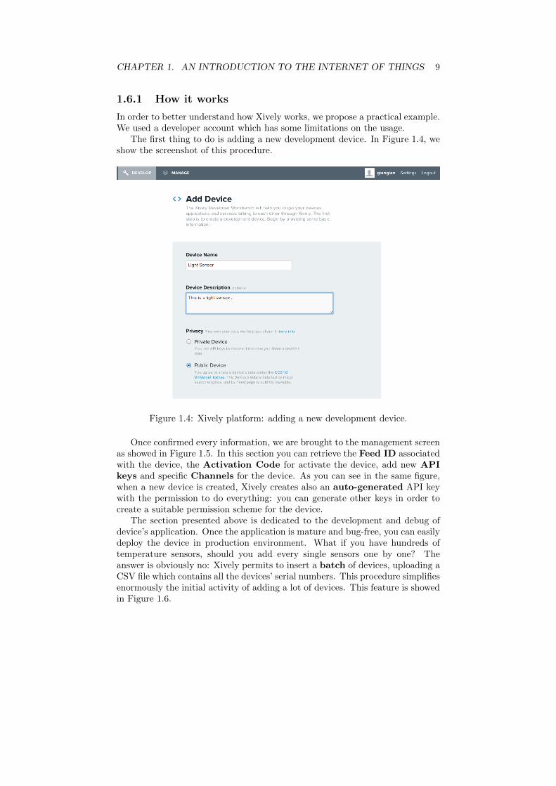
1.6.1 How it works
In order to better understand how Xively works, we propose a practical example.We used a developer account which has some limitations on the usage.
The first thing to do is adding a new development device. In Figure 1.4, weshow the screenshot of this procedure.
Figure 1.4: Xively platform: adding a new development device.
Once confirmed every information, we are brought to the management screenas showed in Figure 1.5. In this section you can retrieve the Feed ID associatedwith the device, the Activation Code for activate the device, add new APIkeys and specific Channels for the device. As you can see in the same figure,when a new device is created, Xively creates also an auto-generated API keywith the permission to do everything: you can generate other keys in order tocreate a suitable permission scheme for the device.
The section presented above is dedicated to the development and debug ofdevice’s application. Once the application is mature and bug-free, you can easilydeploy the device in production environment. What if you have hundreds oftemperature sensors, should you add every single sensors one by one? Theanswer is obviously no: Xively permits to insert a batch of devices, uploading aCSV file which contains all the devices’ serial numbers. This procedure simplifiesenormously the initial activity of adding a lot of devices. This feature is showedin Figure 1.6.

CHAPTER 1. AN INTRODUCTION TO THE INTERNET OF THINGS 10
Figure 1.5: Xively platform: device’s resume screen.
Figure 1.6: Xively platform: batch adding.

CHAPTER 1. AN INTRODUCTION TO THE INTERNET OF THINGS 11
1.6.2 Pricing
Xively gives to users three types of service, from an entry-level service to a topone. The main differences among these three types consists in the hours ofavailable consulting support and the price of channels per transaction volume.The service pricing table is showed in Table 1.1.
Starter Value Select
PrioritySupport
12 hours 12 hours 12 hours
ConsultingServices
6 hours 20 hours 48 hours
ChannelPricing
Low: $1.25Average: $2.00High: $3.25
Low: $0.99Average: $1.55High: $2.50
Low: $0.65Average: $0.99High: $1.25
Price 999$/year 4,900$/year 39,000$/year
Table 1.1: Xivley service pricing table.


Chapter 2
The iCore Project
iCore is a EU funded project which has two main objectives:
• abstracting the technological heterogeneity which comes from the hugeamount of heterogeneous objects, while maintaining the reliability ;
• considering the views of different users and stakeholders in order to ensureproper application provision, business integrity and exploiting businessopportunities.
In order to run a mashup, we need a platform in which users can deploy thesecomposite services and execute them. Stecca and Maresca in [15] proposed aplatform, based on a Request/Response model, that supports the execution ofserver-side/event-drive mashups. In the following sections, we will describethe two main components of this platform, the service creation platform(SCP) and the service execution platform (SEP): the former permits thecreation of mashups and the latter permits their execution.
2.1 Service Creation Platform
The creation of a mashup is made through a graphical interface in which cre-ators can drag and drop blocks representing services and define the relationshipsbetween them by drawing an edge from the emitting service to the receivingone, as shown in Figure 3.1. Once the mashup is created, it is saved as an XMLfile and stored in a repository. An example of the editor is shown in Figure 2.1.
13

CHAPTER 2. THE ICORE PROJECT 14
Figure 2.1: Graphical user interface for creating mashups.
2.2 Service Execution Platform
The service execution platform is the actual environment in which mashups liveand compute. It has to satisfy a set of requirements, such as:
• Scalability: the system has to support the simultaneous execution ofa possible large number of instances (also called sessions) on differenthardware size;
• Fault Tolerance: the system has to ensure that even if some componentsfail, the session is able to continue its execution;
• Low latency and high throughput: The system has to serve as manyrequests as possible, according to the hardware characteristics;
• Authentication, Authorization and Accounting (AAA): the systemhas to guarantee the opportunity of managing users’ permissions, differentservice levels (SL) and authorization;
• Management: the system has to permit a full control over the availableresources in order to allow to the platform administrator the application ofnecessary maintenance operations (e.g. enforcing Service Level Agreementrules).

CHAPTER 2. THE ICORE PROJECT 15
2.2.1 Service Proxy
Although the existing services use standard interfaces (e.g. RESTful API,SOAP) to expose their resources, they do not expose interfaces compatible withevent-driven platform because of the different technologies and different dataformats (e.g. XML, JSON, YAML). In order to ensure the compatibility withthe system, Stecca and Maresca introduced a layer between the internal systemand the external world. They defined the concept of Service Proxy (SP): anSP wraps an external resource and makes it compliant with the event drivenmodel previously explained. Given this concept, a different SP is needed foreach external resource we want to make available in this platform. SP trans-lates input properties into specific external service format and parses the serviceresponse to fulfill the output properties, as shown in Figure 2.2.
Service Proxy
External ResourceRequest from
Orchestrator
Translation to external resource format
Parse from external resource format
Figure 2.2: How a SP interacts with external world.
In order to receive events from the orchestrator node (ON), SPs expose aprimitive called invokeAction through which the ON activate the SP function-ality. Within a SP, we can identify two types of communication:
• Mashups level, which refers to the invokeAction/notifyEvent calls inrelation to the mashup logic;
• External resource level, which refers to the communication between thewrapper SP and the external service.
As we said before, only one SP is needed for each external resources al-though several instance of the same SP can be deploy for performance andfault tolerance reasons.
2.2.2 Orchestrator
The component that actually executes mashups according to defined constrainsis called orchestrator. This software executes mashups logic combining servicesas defined in the SCP. As we said in the previous section, the orchestrator doesnot communicate directly to the external services but it receives and forwardsevents from and to SPs inside the Service Provider Domain (SPD). Figure 2.3depicts the platform architecture and how the orchestrator works.

CHAPTER 2. THE ICORE PROJECT 16
Service Provider Domain
Orchestrator
SP1 SP2
External
Services
SPn
Figure 2.3: High level platform architecture.
In the platform, a single ON is needed but, for performance reasons, severalinstances may coexist at the same time. When a new deployment request ar-rives, each active ON retrieves from repository the XML representation of therequested mashup. According to the XML, ON translates it to a Routing Table
that is used for managing the mashup logic during its execution. Each table en-try is identified by the pair <senderSPId, eventId>, through which the ONcan get the information required for invocation of the next action or actions inthe mashup.
Regarding a single action, the required information for the correct forwardingof the next action are:
• the identifier of the next action;
• the identifier of the next SP;
• the parameters assignment from output to input values.
Now we have a clear idea about which information is needed to correctlyexecute the mashup. Next step is to define the algorithm through which acomposite service runs. When an event occurs on an ON, the steps to follow aredescribed in Algorithm 1:

CHAPTER 2. THE ICORE PROJECT 17
Algorithm 1 Next action(s) invocation algorithm.
1: NEXT ACTION(EventId, SenderSPId, SessionId, Properties)2: MashupId ← SessionId.MashupId
3: RoutingTable ←getRoutingTable(MashupId)
4: entries ← RoutingTable.getEntries(<SenderSPId, EventId>)
5: for all entry ∈ entries do6: Update Properties based on assignment fields.7: entry.nextSP.invokeAction(ONEndPoint, ActionId, TargetSPId,
SessionId, UpdateProperties)
8: end for
As we can see in Algorithm 1, invoking next action, ON includes its endpointas a parameter: this is due to the possibility that many ONs exist on the plat-form simultaneously and SP has to be able to notify the correct ON. Switchingbetween ONs supports load balancing, scalability and fault tolerance.
Another important feature of orchestration mechanism is that no state infor-mation is stored during a mashup session: we refer to this property as statelessorchestration.
The mechanism listed in Algorithm 1 is depicted in Figure 2.4.
SP1
SP3
SP2 SP1
ON1
ON2
SP5SP4
Services Container Services Container
invokeAction invokeAction
notifyEvent
notifyEvent
Orchestrators Container
Figure 2.4: Run time execution model.

CHAPTER 2. THE ICORE PROJECT 18
The platform described in this section is suitable for mashups of web servicesbut with emerging of the Internet of Things, where thousands and thousands ofdevices and smart objects can be mixed with web services, this platform does notwork as desired. The system architecture does not scale with the huge amountof new entities which want to be integrate to the platform.
The solution to this problem comes from the distributed system literature andit is called publish-subscribe architecture. These architectures guaranteescaling property and asynchronous communications which are fundamental insmart objects implementation and functionality (e.g. sensors).
The next chapter will introduce the publish-subscribe (P/S) architecture andpropose a lightweight and P/S compliant protocol which is designed to be usedin constrained applications such as the IoT ones.

Chapter 3
A publish-subscribeprotocol: MQTT
The Internet gives a huge amount of free services which carry out different jobs,such as mail services, RSS feeds, Flickr R© flows, etc. We can combine all theseservices into new custom composite services which enrich the benefits of everysingle service. We name this combination of services as a mashup. Figure 3.1shows an example of mashup.
Figure 3.1: An example of mashup.
The idea behind this concept is really simple: each service exposes a set ofactions it can execute and a set of events it can fire up. Using this paradigm,we can build chains of services which receive data from a service and produceinformation that can be used by another service. The above example has beenbuilt for a park searching assistant installed into a car. In this composite servicewe have six different services:
• Speed: the service reads the current car speed and fires an event when anew speed value is available;
• GPS: the service retrieves a GPS location and fires an event when a newlocation is available;
• Parking service: given a GPS location, the service gives the nearestfree parking station from that location and fires an event when a parkingstation is available;
19

CHAPTER 3. A PUBLISH-SUBSCRIBE PROTOCOL: MQTT 20
• Database service: given a set of information, the service saves theseinformation in a database and fires an event when data are correctly savedinto the database;
• Display: given a string, the service writes a string on the car’s displayand fires an event when the write process ends;
• Proximity: the service monitors the distance between a given GPS loca-tion and the current location and fires an event when this distance is belowa defined threshold.
Platforms, which permits the creation of personalized mashups, already exist:they provide graphical tools in order to build up composite services without anyparticular programming skill. Such services includes Yahoo! Pipes1, JackBePresto Server2 and Apatar3.
After a brief recall of publish-subscribe systems, we will introduce MQTTwhich are at the new platform fundamental components.
3.1 Publish-Subscribe Systems
The publish-subscribe paradigm is an event-based architecture in which pub-lishers publish structured events to an event service (usually called broker) andsubscribers show their interest in a particular event through subscriptions; thesesubscriptions can be custom patterns over the structured events.
These systems are used in several application domains, in particular thoserelated to a large-scale events airing. Examples include:
• financial information systems;
• applications with live feeds of real-time data (including RSS feeds);
• support for cooperative working where users need to be informed of eventsof interest;
• support for ubiquitous computing, including the management of events em-anating from ubiquitous infrastructure (i.e. location events);
• a broad set of monitoring applications, including network monitoring inthe Internet.
This type of system is a key component of Google’s infrastructure, i.e. in thedissemination of events related to advertisements [4].
Publish-Subscribe systems have two main characteristics:
Heterogeneity In a scenario where event notifications are used as a communi-cation media, components in a distributed system that were not design forinteroperability can be made to work together. The only required thing isthat the event-generating objects publish the events they offer, and thatother object can subscribe to event topics (i.e. communication channels)and provide a suitable interface for receiving and dealing with event noti-fications.
1http://pipes.yahoo.com2http://www.jackbe.com3http://www.apatarforge.org

CHAPTER 3. A PUBLISH-SUBSCRIBE PROTOCOL: MQTT 21
Asynchronicity Event notifications are sent asynchronously by publishers toall subscribers who are interested in them, in order to prevent the pub-lishers needing to synchronize with subscribers. In other words, publishersand subscribers have to be decoupled.
3.1.1 The programming model
As shown in Figure 3.2, the publish-subscribe model consists of a small set ofoperations:
publish(e) A publisher can disseminate an event e using this primitive;
notify(e) A subscriber can receive an event e which represents a topic updatefrom the publish-subscribe system;
subscribe(t) A client can subscribe to a specific topic t using this primitive;
unsubscribe(t) A client can unsubscribe from a specific topic t using thisprimitive;
advertise(t) A publisher can declare the nature of its future events associatedwith a topic t ;
unadvertise(t) A publisher can revoke advertisements related to a specifictopic t.
Publish-Subscribe System
publish(e1)
publish(e2)
advertise(t2)
notify(e2)
notify(e1)
subscribe(t2)
subscribe(t1)
notify(e1)
Figure 3.2: The publish-subscribe paradigm
These operations are mediated by a publish-subscribe system (a.k.a. bro-ker) which is responsible to dispatch the events from publishers to interestedsubscribers.

CHAPTER 3. A PUBLISH-SUBSCRIBE PROTOCOL: MQTT 22
Centralized and distributed architecture implementations are available.The simplest approach is the centralized one: in this case, every communication(from publishers to broker or from broker to subscribers) takes place through aseries of point to point messages. During its working phase, the broker could bea bottleneck if it is present in a single instance. To prevent these situations,we can replace the broker with a network of brokers that cooperate to offer thedesired functionality and service level.
For further information, see [4].
3.2 Message Queue Telemetry Transport
Message Queue Telemetry Transport (MQTT) is a lightweight broker-basedpublish-subscribe messaging protocol, developed and designed for constraineddevices and low bandwidth by IBM / Eurotech in 1999. Due to simplicity andlow overhead, this protocol is suitable for use in constrained environments, suchas:
• Expensive networks with low bandwidth and no reliability;
• Embedded in devices with limited processor and/or memory resources.
Some other features of this protocol are:
• It provides one-to-many message distribution and decoupling of applica-tions;
• It is agnostic on the content of the payload;
• It is built over TCP/IP for basic network connectivity;
• It provides three different type of Quality of Service:
At most once: messages are delivered according to the best effort ofTCP/IP networks; Message loss and duplication can occur.
At least once: messages are assured to arrive but duplicates may occur.
Exactly once: messages are assured to arrive exactly once.
• It has a small transport overhead;
• It has a mechanism to notify of abnormal disconnection of a client usingthe Last Will and the Testament features.
The protocol is openly published with a royalty-free license and a variety ofclient libraries have been developed, in particular on popular hardware platformssuch as Arduino4.
4http://arduino.cc

CHAPTER 3. A PUBLISH-SUBSCRIBE PROTOCOL: MQTT 23
3.2.1 Message format
The message consists of three parts:
• a fixed header
• a variable header
• a payload.
The message format is depicted in Figure 3.3.
Fixed header
Variable header
47 0
Payload
Figure 3.3: Message format.
Fixed header
The fixed header contains information about the message type, QoS level,some flags and the message length. Figure 3.4 shows the fixed header’s structure.
Message Type DUP Flag QoS Level RETAIN
Remaining Length
byte 1
byte 2
47 0
Figure 3.4: Fixed header’s bits structure.
Message type This field is used to define the message type. It is a 4 bits fieldwhich possible value is listed in Table 3.1.

CHAPTER 3. A PUBLISH-SUBSCRIBE PROTOCOL: MQTT 24
Mnemonic Enumeration Description
Reserved 0 Reserved for future use
CONNECT 1 Client request to connect to broker
CONNACK 2 Connect acknowledgement
PUBLISH 3 Publish message
PUBACK 4 Publish message acknowledgement
PUBREC 5 Publish received (QoS = 2)
PUBREL 6 Publish release (QoS = 2)
PUBCOMP 7 Publish complete (QoS = 2)
SUBSCRIBE 8 Client subscribe request
SUBACK 9 Subscribe acknowledgement
UNSUBSCRIBE 10 Client unsubscribe request
UNSUBACK 11 Unsubscribe acknowledgement
PINGREQ 12 Ping request
PINGRESP 13 Ping response
DISCONNECT 14 Client disconnection request
Reserved 15 Reserved for future use
Table 3.1: Possible message types.
DUP Flag This flag is set when client or server attempts to re-deliver a PUB-LISH, PUBREL, SUBSCRIBE or UNSUBSCRIBE message. The flag isused only on messages that have QoS > 0.
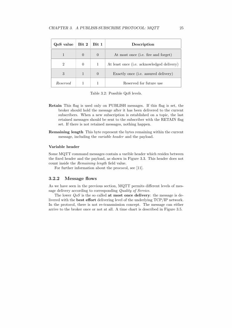
QoS level This flag is used to set the level of delivery assurance for PUBLISHmessages. The possible QoSs are listed in Table 3.2.
CHAPTER 3. A PUBLISH-SUBSCRIBE PROTOCOL: MQTT 25
QoS value Bit 2 Bit 1 Description
1 0 0 At most once (i.e. fire and forget)
2 0 1 At least once (i.e. acknowledged delivery)
3 1 0 Exactly once (i.e. assured delivery)
Reserved 1 1 Reserved for future use
Table 3.2: Possible QoS levels.
Retain This flag is used only on PUBLISH messages. If this flag is set, thebroker should hold the message after it has been delivered to the currentsubscribers. When a new subscription is established on a topic, the lastretained messages should be sent to the subscriber with the RETAIN flagset. If there is not retained messages, nothing happen.
Remaining length This byte represent the bytes remaining within the currentmessage, including the variable header and the payload.
Variable header
Some MQTT command messages contain a varible header which resides betweenthe fixed header and the payload, as shown in Figure 3.3. This header does notcount inside the Remaining length field value.
For further information about the prococol, see [11].
3.2.2 Message flows
As we have seen in the previous section, MQTT permits different levels of mes-sage delivery according to corresponding Quality of Service.
The lower QoS is the so called at most once delivery: the message is de-livered with the best effort delivering level of the underlying TCP/IP network.In the protocol, there is not re-transmission concept. The message can eitherarrive to the broker once or not at all. A time chart is described in Figure 3.5.

CHAPTER 3. A PUBLISH-SUBSCRIBE PROTOCOL: MQTT 26
Client Broker
PUBLISH
• QoS = 0
ACTION:
• Publish message to
subscribers
Figure 3.5: Communication flow with QoS level 0
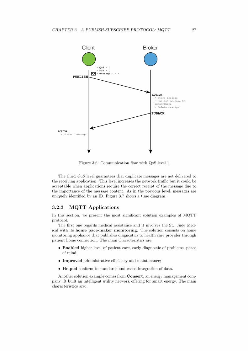
The second QoS level is called at least once delivery: with respect tothe previous QoS, every message is uniquely identified by an ID and every cor-rectly received message is confirmed by an acknowledge, using the PUBACKprimitive. If during the communication a failure is identified or the ACK isnot received after a specified period of time, the client sends again the messagewith the DUP flag set in the fixed header. SUBSCRIBE and UNSUBSCRIBEmessages are sent with QoS level 1. Figure 3.6 shows a time diagram.
CHAPTER 3. A PUBLISH-SUBSCRIBE PROTOCOL: MQTT 27
Client Broker
PUBLISH
PUBACK
ACTION:• Discard message
ACTION:• Store message• Publish message to subscribers• Delete message
• QoS = 1• DUP = 0• MessageID = x
Figure 3.6: Communication flow with QoS level 1
The third QoS level guarantees that duplicate messages are not delivered tothe receiving application. This level increases the network traffic but it could beacceptable when applications require the correct receipt of the message due tothe importance of the message content. As in the previous level, messages areuniquely identified by an ID. Figure 3.7 shows a time diagram.
3.2.3 MQTT Applications
In this section, we present the most significant solution examples of MQTTprotocol.
The first one regards medical assistance and it involves the St. Jude Med-ical with its home pace-maker monitoring. The solution consists on homemonitoring appliance that publishes diagnostics to health care provider throughpatient home connection. The main characteristics are:
• Enabled higher level of patient care, early diagnostic of problems, peaceof mind;
• Improved administrative efficiency and maintenance;
• Helped conform to standards and eased integration of data.
Another solution example comes from Consert, an energy management com-pany. It built an intelligent utility network offering for smart energy. The maincharacteristics are:

CHAPTER 3. A PUBLISH-SUBSCRIBE PROTOCOL: MQTT 28
Client Broker
PUBLISH
PUBREL
PUBREC
PUBCOMP
ACTION:
• Store message
• QoS = 2
• DUP = 0
• MessageID = x
ACTION:
• Discard message
ACTION:
• Store message
or
ACTIONS:
• Store message ID
• Publish message to
subscribers
ACTIONS:
• Publish message to
subscribers
• Delete message
or
ACTION:
• Delete message ID
• MessageID = x
• MessageID = x
• MessageID = x
Figure 3.7: Communication flow with QoS level 2
• Enabled daily energy savings of 15-20%;
• Improved peak usage and avoided over charges;
• Helped optimize energy use.

CHAPTER 3. A PUBLISH-SUBSCRIBE PROTOCOL: MQTT 29
In the social networks era, Facebook [8] used MQTT in its personal messagingapp for mobile subscribers [14]. Facebook experiences some problem of longlatency when sending a message. The method they were using was reliable butit was really slow. They were trying to build up a mechanism that maintains apersistent connection to their servers. In order to do so without killing batterylife, Facebook development team used MQTT that they experimented in Beluga.By maintaining an MQTT connection and routing messages through their chatpipeline, Facebook was able to often achieve phone-to-phone delivery in hundredsof milliseconds, rather than multiple seconds. The main characteristics are:
• Enabled reliable communications between individuals;
• Improved delivery times over high latency connections;
• Helped improve mobile battery life.
3.3 An MQTT implementation: Paho
Paho is a project which has been created to provide scalable open-source im-plementations of open and starndard messaging protocols aimed at new andexisting M2M and IoT applications. Paho is a Maori word which means tobroadcast, make widely known, announce, disseminate, transmit5. Figure 3.8shows the Paho project logo.
Figure 3.8: Paho project logo.
The project started with MQTT publish/subscribe client implementationbut, in the future, it will bring corresponding broker as established by the de-velopers community.
For further information and future developments about this project, see [10].
3.4 Terracotta R© Universal Messaging: settingup a local environment
In this section we are going to explain a brief tutorial about how to set up afully functional system with a broker, publishers and subscribers.
There are several MQTT broker implementations available on the Internet,such as Mosquitto6, but in this tutorial we will use Terracotta Universal Mes-saging7(Terracotta UM), developed by Software AG (SAG). Terracotta UM is
5http://www.maoridictionary.co.nz/search?keywords=paho6http://mosquitto.org/7http://terracotta.org/products/universal-messaging

CHAPTER 3. A PUBLISH-SUBSCRIBE PROTOCOL: MQTT 30
an all-in-one solution for messaging standards, compatible with a considerablenumber of messaging protocols (e.g. MQTT and JMS). SAG also provides dif-ferent languages APIs such as Java, C++, .Net, Javascript and mobile (iOS andAndroid), as shown in Figure 3.9.
Enterprise Clients
.NET C++ Java Python
Mobile Clients
iOS AndroidWindows
Phone
Web Clients
JS Comet
HTML5
Web
Socket
Adobe
FlexSilverlight Java
Messaging / Transport Options
Messaging APIsUniversal Messaging, JMS
Wire ProtocolsUniversal Messaging Sockets (+SSL) or HTTP/S,
HTML5 Web Sockets & Comet, MQTT, ...
Transport ProtocolsUnicast, Multicast, IPC (SHM)
Universal Messaging
High Throughput | Low Latency | Secure | Reliable
Figure 3.9: Terracotta Universal Messaging Architecture.
3.4.1 Terracotta Universal Messaging
The system deployment has been done on a Linux machine; Terracotta UMrequires a Java JDK installation. The first thing to do is download the brokeravailable on the SAG site and install it on your own PC. Once downloaded theLinux version, it requires the permission of execution which can be set with thefollowing commands
root# cd <path to downloaded terracotta um bin>root# chmod 777 ./universalmessaging_linux.bin
Now, the downloaded file has permission to execute, so you can start theinstallation process through the command
root# sudo ./universalmessaging_linux.bin -i gui
Using the switch -i gui, you can see the process via a the OS graphical userinterface and not in the terminal console. Following the installation process,you can choose location where Terracotta UM will be; in our case, the selectedlocation is /bin/terracotta.
Once Terracotta UM is installed, you can start the messaging server: to doso, type this line in the terminal
root# cd /bin/terracotta/universalmessaging_<v_number>/links/Server/nirvana
root# sudo ./Start Universal Messaging Realm Server
Typed these command, server boots and it will listen on the addressnhp://0.0.0.0:9000. The default protocol does not permit MQTT commu-nication, so we have to add an interface which guarantees compatibility withMQTT. In order to do this, we have to start the Terracotta UM EnterpriseManager, using the commands:

CHAPTER 3. A PUBLISH-SUBSCRIBE PROTOCOL: MQTT 31
root# cd /bin/terracotta/universalmessaging_<v_number>/links/Administration/nirvana
root# sudo ./Universal Messaging Enterprise Manager
The Manager interface is shown in Figure 3.10.
Figure 3.10: Universal Messaging Enterprise Manager.
It provides a graphical representation of statistics about memory usage, mes-saging and connections status. If you want to manage the MQTT broker, youhave to go to the nirvana section on the manager’s left side. The section isshown in Figure 3.11.
Figure 3.11: Nirvana Manager Section

CHAPTER 3. A PUBLISH-SUBSCRIBE PROTOCOL: MQTT 32
As we said before, the default interface is listening on Universal MessagingHTTP Protocol (nhp) which is not compatible with MQTT. In order to makeit compatible, we will add new interface on the nirvana realm. Go to Commstab and then to Interfaces sub-tab. The presented interface is shown in Figure3.12
Figure 3.12: New Interface Section.
The UM MQTT-compatible protocol is Universal Messaging Socket Pro-tocol (nsp). Add a new interface, clicking on Add interface button and fill theform in Figure 3.13 with the following parameters:
Interface Protocol NSP (Socket Protocol)
Interface Port 9001 (any port > 1024)
Interface Adapter 0.0.0.0 (localhost)
Figure 3.13: New interface parameters.
Once pressed the confirm button, start the interface by clicking on the relatedbutton on the Status column.

CHAPTER 3. A PUBLISH-SUBSCRIBE PROTOCOL: MQTT 33
In order to add custom topics to which clients can subscribe to or publish in,right-click the nirvana icon on the left sidebar and then to Add Channel. Thepresented form is shown in Figure 3.14.
Figure 3.14: New channel form.
We fill it with the desired Channel Name (test/dev) and leaving blank theothers fields.
The created channel is added on the left sidebar, as shown in Figure 3.15,butit does not have any read/write permissions.
Figure 3.15: New channel icon on the left sidebar.
In order to add permissions to the channel, select the dev channel, go to ACLtab and click the Add button. The presented interface requires to add the userand the host of the related permission with a specified syntax (user@host), asshown in Figure 3.16. In our example, we do not set any particular user, so weadd the ACL which permits to every users on locahost to access this channel;the specific string is *@localhost.

CHAPTER 3. A PUBLISH-SUBSCRIBE PROTOCOL: MQTT 34
Figure 3.16: New channel permission form.
Once confirmed, a row appears in the ACL tab as shown in Figure 3.17. ClickFull section to allows users subscription, publishing, naming, ACL managementand purging.
Figure 3.17: List of channel’s permission.
These are the basic steps to do in order to set up the Terracotta UM server.In the next section we will present a simple implementation of two clients, onewill work as publisher and another one will work as subscriber.
3.4.2 Client Implementation with Paho MQTT
In this section we will provide a simple implementation of a publisher and asubscriber which can exchange messages each other. During this example we willkeep separate the publisher and the subscriber functionalities to better explainhow they work. Nevertheless, a client can be both publisher and subscriber atthe same time.
Publisher
Since the publisher is a MQTT entity, it has to have a MqttClient in order to ex-change information with the broker. To do so, we instantiate a new MqttClient
in line 22 of Appendix A
MqttClient publisher = new MqttClient(TCPAddress, clientId);
where TCPAddress and clientId are the broker’s address and the unique clientidentifier across the system, respectively.
We connect the client to the broker using the instance method
publisher.connect();
which can accept an object containing connection configuration options but,inthis example, we will use default configuration values.
Now, we are connected to the broker and we can publish on topics. To doso, we retrieve from the publisher object a MqttTopic
MqttTopic t = publisher.getTopic(topic);
through which we can send messages to the specific topic.Sending information are wrapped by a class that provides several methods to
work with. The message quality of service level can be set using the MqttMessagemethod

CHAPTER 3. A PUBLISH-SUBSCRIBE PROTOCOL: MQTT 35
message.setQoS(QoS);
Messages can be sent using the topic previously get and invoking on it thepublish method
MqttDeliveryToken token = t.publish(message);
which returns a MqttDeliveryToken containing communication information.Both synchronous and asynchronous waiting can be possible: the synchronouswaiting can be done using the MqttDeliveryToken,returned by the publish
method, and invoking on it the method
token.waitForCompletion(timeout);
which accept a timeout parameter that represents the maximum amount of timeMQTT client will wait for publishing completion.
The complete publisher implementation can be found in Appendix A.
Subscriber
The MQTT subscriber is quite simple to the publisher with the exception thatsubscriber needs callbacks for managing MQTT events, i.e. arrival of a newmessage, connection loosing and delivery completion. There are two ways toattach these callbacks to client:
• create a new class that implements the MqttCallback interface;
• implements MqttCallback interface on the same subscriber class.
In this example we chose to create a new class which implements the interface.SubscriberCallbacks contains three methods that have to be override in orderto make the class compliant to the interface. These three methods are:
• messageArrived: it shows the arrived message on the standard output;
• deliveryComplete: it shows the token information associated with thedelivery;
• connectionLost: it prints several information about the exception whichcauses the connection lost.
Once implemented the class, we can attach it to the subscriber through thecode
SubscriberCallbacks callbacks =new SubscriberCallbacks(clientId);
subscriber.setCallback(callbacks);
The complete publisher implementation can be found in Appendix B.

Chapter 4
Integrating MQTT into theplatform
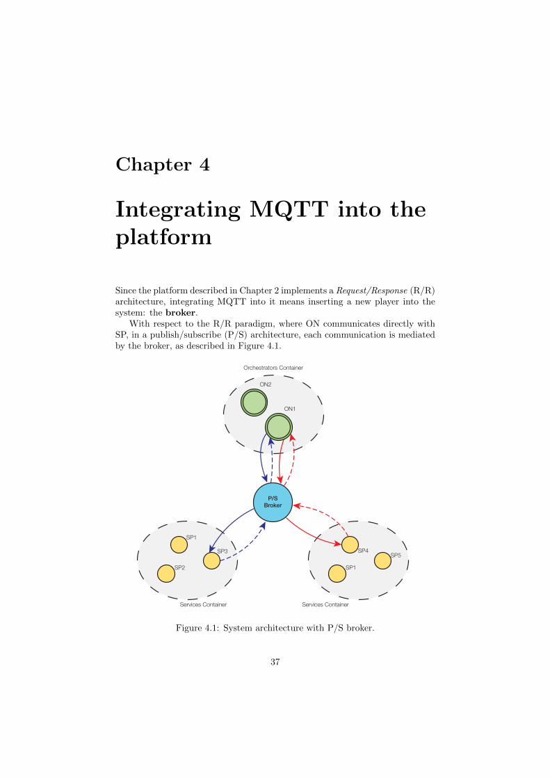
Since the platform described in Chapter 2 implements a Request/Response (R/R)architecture, integrating MQTT into it means inserting a new player into thesystem: the broker.
With respect to the R/R paradigm, where ON communicates directly withSP, in a publish/subscribe (P/S) architecture, each communication is mediatedby the broker, as described in Figure 4.1.
SP1
SP3
SP2 SP1
ON1
ON2
SP5SP4
Services Container Services Container
Orchestrators Container
P/S
Broker
Figure 4.1: System architecture with P/S broker.
37
CHAPTER 4. INTEGRATING MQTT INTO THE PLATFORM 38
It has decided to include a P/S system, and in particular MQTT, in theproject in order to integrate into the platform, not only web services but alsophysical devices which can exchange information from (e.g. sensors) and to(e.g. actuator) the real world.
In the following sections, we will describe two different integration of P/Sparadigm to the platform illustrated in [15]: a centralized and a distributedimplementation.
4.1 Centralized SEP
In the centralized implementation, all the concepts presented in [15] has beenkept: the ON is the only that knows mashups logic, SPs execute in the waydescribed in 2.2.
The information carried by the session message, from ON to SP, are al-most the same as the ones described in 2.2: ActionId, TargetSPId,SessionId,MashUpId and InParameters.
• ActionId: the action identifier we want to invoke on receiver SP;
• TargetSPId: this parameter is used to manage the case in which a mashupcontains multiple instances of a single SP (e.g. <SP ID>.0 or <SP ID>.1);
• SessionId: the identifier of a particular execution of a mashup;
• MashUpId: the mashup identifier;
• InParameters: the container that holds the input parameters related to aspecific SP;
• OutParameters: the container that holds all the output parameters pro-duced by SPs.
Communications between SPs and ON take place through the P/S conceptof topic. Each SP can receive messages subscribing itself to a specific topicwhich has the form /<SP ID>/execute, where <SP ID> is the SP identifier (e.g./GMail/execute can be the topic for a mail SP). Once received the messaged,each SP has to dispatch the invoking action using the information carried by thesession message.
On the other hand, ON can receive information from SP subscribing to/ON/notify: each SP, at the end of action execution, will publish on it in orderto notify ON.
4.1.1 Example
In order to better explain how the platform works, we get to the reader a practicalexample and we will describe every step in the mashup execution. Figure 4.2represents a simple composition of SPs.

CHAPTER 4. INTEGRATING MQTT INTO THE PLATFORM 39
SP1.0 SP2.0 SP3.0
START END
SP1.0/startSP1.0/t1 SP2.0/t3
SP3.0/t5
Figure 4.2: An example of mashup.
SPs can exchange output parameters between them, i.e. output parametersof a SP can be input parameters of another one: in SCP, the mashup creatorcan define these connections placing a placeholder as parameter value (e.g.SPMail.0.in.body = ${LightSensor.0.out.intensity} will set the mail’sbody to intensity value outputted by the light sensor).
Deployment
The deployment phase of a mashup consists of retrieving its XML representationstored in the repository, generate the routing table and keep it in memory. Thetable generated for mashup in Figure 4.2 is described in Table 4.1:
Publisher Subscriber Topic Parameters
START SP1.0 SP1.0/start
SP1.0 SP2.0 SP1.0/t1"SP1.0.in.prop1" : 0.5,
"SP1.0.in.prop2" : "sword"
SP2.0 SP3.0 SP2.0/t3
"SP2.0.in.prop1" :
"${SP1.0.out.prop1}","SP2.0.in.prop2" : 4
SP3.0 END SP3.0/t5
"SP3.0.in.prop1" :
"${SP1.0.out.prop3}","SP3.0.in.prop2" :
"${SP2.0.out.prop2}
Table 4.1: Routing table for mashup in Figure 4.2.
Execution
Execution steps are depicted in Figure 4.3.Since the ON manages the entire mashup execution, when the ON receives a
SP’s session message, it looks up the routing table, it retrieves the SP (possiblySPs) that has to be execute afterwards, modifying the session message.
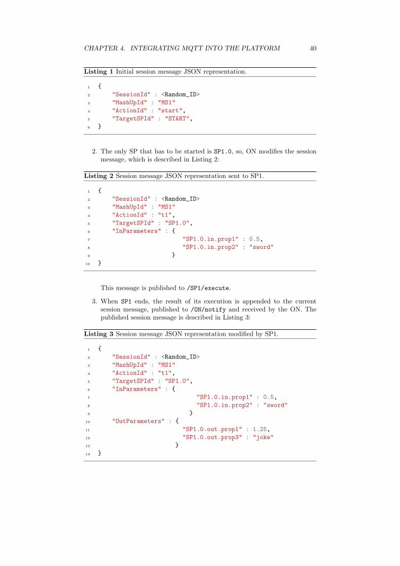
1. START SP creates the session message in Listing 1 and publishes it to/ON/notify:
CHAPTER 4. INTEGRATING MQTT INTO THE PLATFORM 40
Listing 1 Initial session message JSON representation.
1 {
2 "SessionId" : <Random_ID>
3 "MashUpId" : "MS1"
4 "ActionId" : "start",
5 "TargetSPId" : "START",
6 }
2. The only SP that has to be started is SP1.0, so, ON modifies the sessionmessage, which is described in Listing 2:
Listing 2 Session message JSON representation sent to SP1.
1 {
2 "SessionId" : <Random_ID>
3 "MashUpId" : "MS1"
4 "ActionId" : "t1",
5 "TargetSPId" : "SP1.0",
6 "InParameters" : {
7 "SP1.0.in.prop1" : 0.5,
8 "SP1.0.in.prop2" : "sword"
9 }
10 }
This message is published to /SP1/execute.
3. When SP1 ends, the result of its execution is appended to the currentsession message, published to /ON/notify and received by the ON. Thepublished session message is described in Listing 3:
Listing 3 Session message JSON representation modified by SP1.
1 {
2 "SessionId" : <Random_ID>
3 "MashUpId" : "MS1"
4 "ActionId" : "t1",
5 "TargetSPId" : "SP1.0",
6 "InParameters" : {
7 "SP1.0.in.prop1" : 0.5,
8 "SP1.0.in.prop2" : "sword"
9 }
10 "OutParameters" : {
11 "SP1.0.out.prop1" : 1.25,
12 "SP1.0.out.prop3" : "joke"
13 }
14 }

CHAPTER 4. INTEGRATING MQTT INTO THE PLATFORM 41
4. Once the ON receives the session message in Listing 3, it looks up in therouting table for finding what to do. From Table 4.1, using TargetSPId
as key, ON retrieves that SP2.0 is the next SP to invoke. ON checksthe parameters container and finds that it contains a placeholder (i.e.${SP1.0.out.prop1}): with this placeholder, it goes to OutParameters
field of the current session message and retrieves the value (e.g. 1.25).Afterwards, the session message published to /SP2/execute is listed inListing 4:
Listing 4 Session message JSON representation published to SP2.
1 {
2 "SessionId" : <Random_ID>
3 "MashUpId" : "MS1"
4 "ActionId" : "t3",
5 "TargetSPId" : "SP2.0",
6 "InParameters" : {
7 "SP2.0.in.prop1" : 1.25,
8 "SP2.0.in.prop2" : 4
9 }
10 "OutParameters" : {
11 "SP1.0.out.prop1" : 1.25,
12 "SP1.0.out.prop3" : "joke"
13 }
14 }
5. Once again, SP2 appends to the OutParameters its execution results andpublished session message is listed in Listing 5:
Listing 5 Session message JSON representation published to ON by SP2.
1 {
2 "SessionId" : <Random_ID>
3 "MashUpId" : "MS1"
4 "ActionId" : "t3",
5 "TargetSPId" : "SP2.0",
6 "InParameters" : {
7 "SP2.0.in.prop1" : 1.25,
8 "SP2.0.in.prop2" : 4
9 }
10 "OutParameters" : {
11 "SP1.0.out.prop1" : 1.25,
12 "SP1.0.out.prop3" : "joke",
13 "SP2.0.out.prop2" : 3.1415
14 }
15 }
6. ON receives this session message and applies the same rule used before, it

CHAPTER 4. INTEGRATING MQTT INTO THE PLATFORM 42
produces the new session message, which will be published to /SP3/execute,in Listing 6:
Listing 6 Session message JSON representation published to SP3.
1 {
2 "SessionId" : <Random_ID>
3 "MashUpId" : "MS1"
4 "ActionId" : "t5",
5 "TargetSPId" : "SP3.0",
6 "InParameters" : {
7 "SP3.0.in.prop1" : "joke",
8 "SP3.0.in.prop2" : 3.1415
9 }
10 "OutParameters" : {
11 "SP1.0.out.prop1" : 1.25,
12 "SP1.0.out.prop3" : "joke",
13 "SP2.0.out.prop2" : 3.1415
14 }
15 }
7. SP3 executes and appends its results to the OutParameters. The result-ing session message (which will be published on /ON/notify) is listed inListing 7:
Listing 7 Session message JSON representation published to ON by SP3.
1 {
2 "SessionId" : <Random_ID>
3 "MashUpId" : "MS1"
4 "ActionId" : "t5",
5 "TargetSPId" : "SP3.0",
6 "InParameters" : {
7 "SP3.0.in.prop1" : "joke",
8 "SP3.0.in.prop2" : 3.1415
9 }
10 "OutParameters" : {
11 "SP1.0.out.prop1" : 1.25,
12 "SP1.0.out.prop3" : "joke",
13 "SP2.0.out.prop2" : 3.1415,
14 "SP3.0.out.prop2" : "goo.gl/Bf51X4"
15 }
16 }
8. ON receives the session message sended by SP3 and it checks what is goingto do. SP3 is the last block in the composite service and therefore ONpublishes to END/execute the session message just received. This eventends the mashup execution.

CHAPTER 4. INTEGRATING MQTT INTO THE PLATFORM 43
SP1
1: publish(/ON/notify)
3: publish(/ON/notify)
5: publish(/ON/notify)
7: publish(/ON/notify)
2: publish(/SP1/execute)
4: publish(/SP2/execute)
6: publish(/SP3/execute)
8: publish(/END/execute)
START
SP2
SP3
END
BROKER
ON
Figure 4.3: Centralized SEP communication diagram.
CHAPTER 4. INTEGRATING MQTT INTO THE PLATFORM 44
4.2 Distributed SEP
The distributed SEP differs from the centralized one for several reasons. Themashup execution is not managed by a central node but every SP is responsiblefor a part of the SPs chain.
The orchestrator node is replaced by a new entities that we called deploy-ment manager (DM). Starting from the same table structure in Table 4.1, DMcreates special messages, called deployment messages which are sent to theSP during the deployment phase. Since the mashup logic is distributed on theSPs, there is the need to identify multiple deployed mashups and to managemultiple instances of the same SP in a mashup. To do so, we have introduced atoken which identifies uniquely each edge in the mashup graph representation.
Different topics are associated to each SP: each SP has as many topics as theactions available, moreover, it has some administration topics through whichSP can be notified of deployment or undeployment events.
The next two sections explain in a detailed way how deployment and execu-tion phases work.
Deployment
As said in the introduction of distrubuted SEP, we introduced a new messagecalled deployment message. The deployment message is based on the samerouting table structure described in Table 4.1.
A deployment message contains:
• Mashup Id: this field identifies mashup which the deployment messagebelongs to;
• SP Counter: this field is used to distinguish multiple repetitions of thesame SP in a mashup;
• Subscription Topic: this is the topic to which SP has to subscribe inorder create the chain;
• Publishing Topic: this is the topic on which SP has to publish in orderto create the chain. This represents also the action that will be executedon the SP;
• Subscription Token: this is the random token that SP has to receivefrom the previous SP;
• Publishing Token: this is the random token that SP has to send to thenext SP;
• In Parameters: this is a collection of SP input parameters used by theservice. This collection can contain parameters whose values are place-holders.
In this scenario, a SP can receive multiple deployment messages, one messagefor each SP instance in the mashup.
Once DM published these messages on the SP’s administration topics, eachSP maintains a special data structure that facilitate deployed mashup admin-istration. A SP uses two maps in order to maintain and manage the users’requests during the mashup execution:

CHAPTER 4. INTEGRATING MQTT INTO THE PLATFORM 45
• Mashups Map: this map contains one element for each deployed mashupon the platform. A map element is composed by a key and a value; it hasthe Mashup Id as a key and a list of subscription tokens as value. Sincea single SP can be added multiple times in a mashup, therefore it can belocated in different places inside the composite service, the list representsall instances of the same SP that are in the mashup;
• Tokens Map: this map contains one element for every single SP instancein the mashup. It has the subscription token as key and a object repre-senting the action configuration information required for the SP execution.
When a new deployment message arrives, SP updates its maps, i.e. it addsthe mashup id to the mashups map, if it does not exists, and adds the subscriptiontoken to the correspondent list. Once updated the mashups map, SP adds theaction’s information object to tokens map using subscription token as key; theinformation object will contain publishing topic, publishing token, subscriptiontopic, SP counter, in parameters and action type. Then, it subscribes itself tothe subscription topic defined in the just received deployment message.
In addition to general SPs, the platform needs two special SP: a START SPwhich assigns a session id and starts a mashup execution, and a END SP whichcollects all the final SP results.
After the deployment phase, all the mashup execution is managed by eachSP and there is no need of any external entity operation.
Execution
During the execution of a mashup, SP receives from a topic and publishes onanother one. All the information about a specific mashup execution is storedin a session message and it travels along the composite service saving all theoutput values. A session message contains:
• Mashup Id: this field identifies which mashup is running;
• Session Id: this field identifies uniquely a mashup execution;
• Token: this field identifies uniquely a connection between two SP;
• Out Parameters: this container holds all the SP’s results, from the be-ginning to the end.
Throughout the execution, every SP will modify the token session propertywith the token that next SP expects and add to the out parameters the SPexecution result. An example will better explain how this mechanism works.
4.2.1 Example
The SP configuration is the same proposed in Section 4.1.1.
Deployment
The communication diagram is depicted in Figure 4.4.

CHAPTER 4. INTEGRATING MQTT INTO THE PLATFORM 46
1. Starting from the routing table in Table 4.1, DM assigns different randomtokens to each connection. In case of multiple listeners on the same topic,the publishing token will be the same for specific connections. Table 4.2summarizes the tokens associated with each connection.
Publisher Subscriber Topic Token
START SP1.0 SP1.0/start T1
SP1.0 SP2.0 SP1.0/t1 T2
SP2.0 SP3.0 SP2.0/t3 T3
SP3.0 END SP3.0/t5 T4
Table 4.2: Communication links tokens.
The deployment process will produce the following deployment messages:
Listing 8 START SP deployment message.
1 {
2 "MashUpId" : "MS1",
3 "PublishingTopic" : "SP1/start",
4 "PublishingToken" : T1,
5 "StartingSP" : "SP1"
6 }
Listing 9 SP1 deployment message.
1 {
2 "MashUpId" : "MS1",
3 "SPCounter" : 0,
4 "PublishingTopic" : "SP1/t1",
5 "PublishingToken" : T2,
6 "SubscribingTopic" : "SP1/start",
7 "SubscribingToken" : T1
8 }
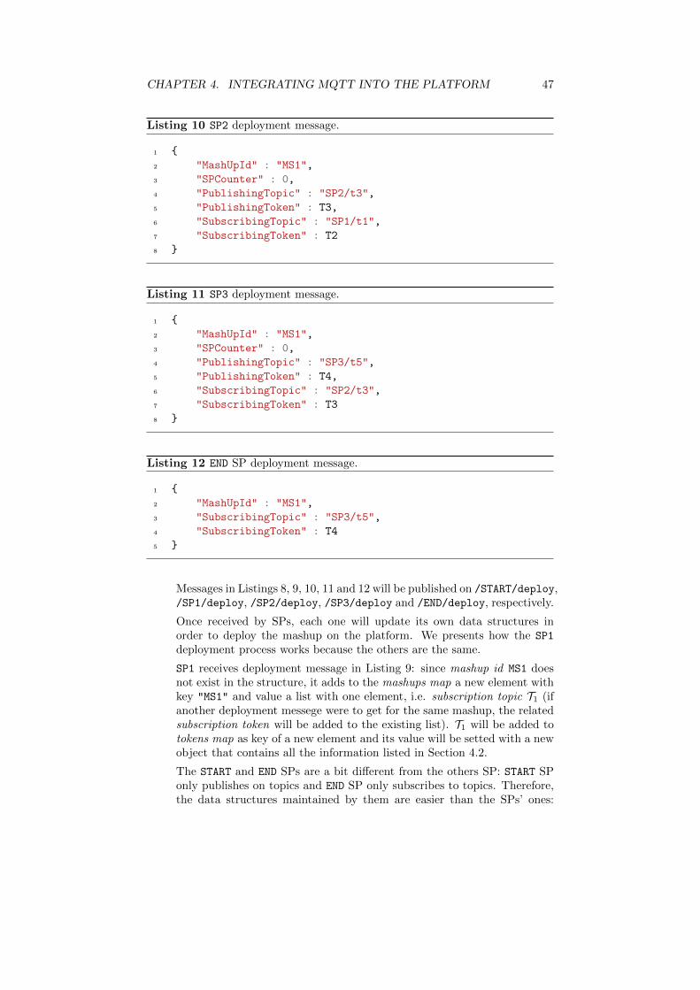
CHAPTER 4. INTEGRATING MQTT INTO THE PLATFORM 47
Listing 10 SP2 deployment message.
1 {
2 "MashUpId" : "MS1",
3 "SPCounter" : 0,
4 "PublishingTopic" : "SP2/t3",
5 "PublishingToken" : T3,
6 "SubscribingTopic" : "SP1/t1",
7 "SubscribingToken" : T2
8 }
Listing 11 SP3 deployment message.
1 {
2 "MashUpId" : "MS1",
3 "SPCounter" : 0,
4 "PublishingTopic" : "SP3/t5",
5 "PublishingToken" : T4,
6 "SubscribingTopic" : "SP2/t3",
7 "SubscribingToken" : T3
8 }
Listing 12 END SP deployment message.
1 {
2 "MashUpId" : "MS1",
3 "SubscribingTopic" : "SP3/t5",
4 "SubscribingToken" : T4
5 }
Messages in Listings 8, 9, 10, 11 and 12 will be published on /START/deploy,/SP1/deploy, /SP2/deploy, /SP3/deploy and /END/deploy, respectively.
Once received by SPs, each one will update its own data structures inorder to deploy the mashup on the platform. We presents how the SP1
deployment process works because the others are the same.
SP1 receives deployment message in Listing 9: since mashup id MS1 doesnot exist in the structure, it adds to the mashups map a new element withkey "MS1" and value a list with one element, i.e. subscription topic T1 (ifanother deployment messege were to get for the same mashup, the relatedsubscription token will be added to the existing list). T1 will be added totokens map as key of a new element and its value will be setted with a newobject that contains all the information listed in Section 4.2.
The START and END SPs are a bit different from the others SP: START SPonly publishes on topics and END SP only subscribes to topics. Therefore,the data structures maintained by them are easier than the SPs’ ones:

CHAPTER 4. INTEGRATING MQTT INTO THE PLATFORM 48
START SP has only a map that maintains an object that contains list offirst-to-execute SPs and the publishing token, associated to the mashup idkey. On the other hand, the END SP maintains a map that associates tothe mashup id, an object that contains a list of subscription tokens.
Execution
2. Mashup execution starts from START SP: it knows which SPs have to befirst executed. In our example, the SP that has to be started is SP1,therefore, START SP creates the session message listed in Listings 13 andit publishes this message on /SP1/start.
Listing 13 Initial session message.
1 {
2 "MashUpId" : "MS1",
3 "SessionId" : <sessionId1>,
4 "CommunicationToken" : T1
5 }
3. When SP1 recevies the session message, using MashupId and CommunicationToken,it retrieves the action to be invoked and the information for session mes-sage forwarding. SP1 executes, it modifies the session message as listed inListing 14 and it publishes it on SP1/t1.
Listing 14 Session message forwarded by SP1.
1 {
2 "MashUpId" : "MS1",
3 "SessionId" : <sessionId1>,
4 "CommunicationToken" : T2,
5 "OutParameters" : {
6 "SP1.0.out.prop1" : 1.25,
7 "SP1.0.out.prop3" : "joke"
8 }
9 }
4. The same procedure takes place when SP2 receives the session messagefrom SP1. Using the MashupId and the CommunicationToken, it gets theaction and, given that the input parameters contain placeholders, SP2 willsubstitute the actual parameters values from the session message. There-fore, it modifies the session message as in 15 and it publishes on /SP2/t3.

CHAPTER 4. INTEGRATING MQTT INTO THE PLATFORM 49
Listing 15 Session message forwarded by SP2.
1 {
2 "MashUpId" : "MS1",
3 "SessionId" : <sessionId1>,
4 "CommunicationToken" : T3,
5 "OutParameters" : {
6 "SP1.0.out.prop1" : 1.25,
7 "SP1.0.out.prop3" : "joke",
8 "SP2.0.out.prop2" : 3.1415
9 }
10 }
5. SP3 receives the session message and it invokes the action. Since the inputparameters contain placeholders, SP3 will fetch the actual values form thesession message, specifically from the OutParameters. Then it modifiesthe session message as in Listing 16 and it publishes on /SP3/t5.
Listing 16 Session message forwarded by SP3.
1 {
2 "MashUpId" : "MS1",
3 "SessionId" : <sessionId1>,
4 "CommunicationToken" : T4,
5 "OutParameters" : {
6 "SP1.0.out.prop1" : 1.25,
7 "SP1.0.out.prop3" : "joke",
8 "SP2.0.out.prop2" : 3.1415,
9 "SP3.0.out.prop2" : "goo.gl/Bf51X4"
10 }
11 }

CHAPTER 4. INTEGRATING MQTT INTO THE PLATFORM 50
SP1
2: publish(/SP1/start)
3: publish(/SP1/t1)
4: publish(/SP2/t3)
5: publish(/SP3/t5)
1: publish(/START/deploy)
publish(/SP1/deploy)
publish(/SP2/deploy)
publish(/SP3/deploy)
publish(/END/deploy)
START
SP2
SP3
END
BROKER
DM
Figure 4.4: Distributed SEP communication diagram.

CHAPTER 4. INTEGRATING MQTT INTO THE PLATFORM 51
Centralized Distributed
SP λ requests/s λ requests/s
ON n× λ requests/s n/a
Broker 2× n× λ requests/s n× λ requests/s
Table 4.3: Loading comparison of centralized and distributed implementation.
4.3 Centralized and distributed implementationcomparison
Each proposed solution has some pros and some cons. The distributed SEP hasthe main advantage that it scales properly with the number of possible servicesand devices. If a single SP can not be sufficient due to a large amount of requests,clusters of SPs can be created in order to supply a better service level. Therun-time bottleneck, that in the centralized version was the orchestrator, in thisimplementation does not exist.
On the other hand, centralized SEP makes easy the accounting of resourcesin a pay-per-use manner.
Comparisons can be made on the load each SP could be subject to during itsworking life cycle. Suppose to have the composite service in Figure 4.2, whichhas three different SPs (i.e. SP1, SP2 and SP3) and two edges SPs (i.e. START
and END).If the system is loaded by λ requests/s, in the centralized version each SP
will manage λ requests/s (in the hypothesis that a single instance exists in themashup, otherwise m× λ, where m is the number of instances of a single SP inthe mashup) but the orchestrator node will be loaded by n×λ requests/s (wheren is the number of SPs in the requested mashup). The broker should managea requests rate of 2 × n × λ requests/s, due to the request-response invocationmechanism.
In the distributed version, the SP loading is the same as before but the brokerloading reduces to n×λ requests/s, since every SP talks directly to the followingSP (possibly, SPs). Table 4.3 summarizes the results.
Another characteristic that can be compared is the number of topics cre-ated in the two versions. In the centralized one, one topic for each SP is cre-ated (i.e. <SP ID>/execute) in addition to the orchestrator node topic (i.e.ON/notify). Therefore, the total number of topics that the broker has to man-age is n+ 1, where n is the number of SP available in the platform.
In the distributed version, a topic for each available action in the SP is createdplus the administration topics, so, supposing that each SP has m actions, andthat n SPs are available in the platform, the broker has to manage (m+ 3)× ntopics.


Conclusion and futuredevelopments
In the first part of this work, we introduced the Internet of Things, a studyabout the semantic meaning of it and the Web of Things, a specialization ofIoT. We have seen that some companies built their core businesses on creatingplatforms that support the emerging Internet of Things, such as Xively.
The platform presented in [15] by Stecca and Maresca has been the startingpoint of the project developed in this thesis.
Enabling devices to be part of this platform has been the focus objective.Not only web services but also smart object which can be combined to createcustom services that perform personalized actions.
As we have seen in Chapter 2, the platform proposed in [15] does not scaleas desired and, in order to support both devices and web services into it, werearranged the platform in a publish-subscribe way. Two solutions were beenproposed, both of them were P/S enabled.
The first one was a translation from the request-response to the publish-subscribe paradigm: the concepts introduced in [15] were been maintained andadapted to the new architecture, as described in Section 4.1.
The second solution was much more innovative: we removed the orches-trator node and introduced the deployment manager. We distributed themashup knowledge into each service proxy, splitting the composite service logic.The deployment manager is responsible to distribute the mashup logic knowl-edge among service proxies, in order to guarantee the correct functionality ofthe entire composite service.
The implemented platform will be integrated into the iCore project in thefuture, when more performance tests will be attempted.
As part of an evolving project, the application scenarios are continuouslychanging but the most important concern smart home, smart city, smartmeeting and smart business.
Another important future development will be the creation of a SoftwareDevelopment Kit (SDK) in order to enable third party developers to createcustom service proxies and, therefore, enlarge the service proxies available to theplatform.
53


Appendix A
Publisher Java Code
1 package mqtt.paho.example1;2
3 import org.eclipse.paho.client.mqttv3.MqttClient;4 import org.eclipse.paho.client.mqttv3.MqttException;5 import org.eclipse.paho.client.mqttv3.MqttTopic;6 import org.eclipse.paho.client.mqttv3.MqttMessage;7 import org.eclipse.paho.client.mqttv3.MqttDeliveryToken;8 import java.util.Scanner;9
10 public class MQTTPublisher {11
12 public static String TCPAddress = "tcp://127.0.0.1:9001";13 public static String topic = "test/dev";14 public static String payload = "";15 public static int QoS = 2;16 public static int timeout = 10000;17 public static String clientId = "publisher_1";18
19 public static void main(String[] args) {20 try {21
22 MqttClient publisher = new MqttClient(TCPAddress, clientId);23
24 Scanner reader = new Scanner(System.in);25 System.out.println("Write messages...");26 System.out.print("# ");27 payload = reader.nextLine();28 publisher.connect();29 while (!payload.equalsIgnoreCase("$quit")) {30 MqttTopic t = publisher.getTopic(topic);31 MqttMessage message = new MqttMessage(payload.getBytes());32 message.setQos(QoS);33
34 MqttDeliveryToken token = t.publish(message);
55

APPENDIX A. PUBLISHER JAVA CODE 56
35 System.out.println(" Delivery token \""36 + token.hashCode());37 System.out.flush();38 token.waitForCompletion(timeout);39 System.out.println(" RECEIVED: "40 + token.isComplete());41
42
43 System.out.print("# ");44 payload = reader.nextLine();45 }46 publisher.disconnect();47
48 } catch (MqttException e) {49 e.printStackTrace();50 }51 }52 }

Appendix B
Subscriber Java Code
1 import org.eclipse.paho.client.mqttv3.*;2
3 public class SubscriberCallbacks implements MqttCallback {4 private String instanceData = "";5
6 public SubscriberCallbacks(String instance) {7 this.instanceData = instance;8 }9
10 @Override11 public void messageArrived(String topic, MqttMessage message) {12 System.out.println("Message arrived: " + message.toString());13 System.out.println("Topic: " + topic.toString());14 System.out.println("Instance: " + instanceData);15 }16
17 @Override18 public void connectionLost(Throwable cause) {19 System.out.println("Connection lost on isntance " + instanceData +20 "with cause " + cause.getMessage());21 System.out.println("Reason code: " + ((MqttException) cause)22 .getReasonCode());23 System.out.println("Cause: " + ((MqttException) cause).getCause());24 cause.printStackTrace();25 }26
27 @Override28 public void deliveryComplete(IMqttDeliveryToken token) {29 try {30 System.out.println("Delivery token \"" + token.hashCode() +31 "\" received by instance " + instanceData);32 } catch (Exception e) {33 e.printStackTrace();34 }
57

APPENDIX B. SUBSCRIBER JAVA CODE 58
35 }36
37 }38
39 import org.eclipse.paho.client.mqttv3.*;40 import java.util.Scanner;41
42 public class MQTTSubscriber {43 public static String TCPAddress = "tcp://localhost:9999";44 public static String topic = "test/dev";45 public static int QoS = 1;46 public static int timeout = 10000;47 public static String clientId = "subscriber_1";48 public static void main(String[] args) {49 try {50 MqttClient subscriber = new MqttClient(TCPAddress, clientId);51 SubscriberCallbacks callbacks = new SubscriberCallbacks(clientId);52 subscriber.setCallback(callbacks);53
54 MqttConnectOptions options = new MqttConnectOptions();55 options.setCleanSession(false);56 options.setKeepAliveInterval(20);57
58 System.out.println("Subscribing to topic \"" + topic +59 "for instance " + subscriber.getClientId() + "with QoS = " + QoS);60 subscriber.connect(options);61
62 subscriber.subscribe(topic);63 System.out.println("Press q to QUIT.");64 Scanner scanner = new Scanner(System.in);65 for (String input = ""; !input.equalsIgnoreCase("q");66 input = scanner.nextLine());67
68 subscriber.disconnect();69 System.out.println("Disconnected!");70
71 } catch (Exception e) {72 e.printStackTrace();73 }74
75 }76 }

Bibliography
[1] N. Kroes, G. Santucci, P. Friess et alii, The Internet of Things - New Hori-zons, Halifax UK, 2012
[2] Yinghui Huang and Guanyu Li, Descriptive Models for Internet of Things,International Conference on Intelligent Control and Information Processing,2010
[3] Louise Coetzee and Johan Eksteen, The Internet of Things - Promise forthe Future? An Introduction, IST-Africa Conference Proceedings, 2011
[4] R. Coulouris, J. Dollimore, T. Kindberg and G. Blair, Distributed Systems- Concept and Design, Fifth Edition, Addison-Wesley, 2012
[5] T. Kindberg., J. Barton, J. Morgan, G. Becker, D. Caswell, P. Debaty,G. Gopal, M. Frid, V. Krishnan, H. Morris, J. Schettino, B. Serra andM. Spasojevic, People, Places, Things: Web Presence for the Real World,Mobile Networks and Applications 7, 365–376, 2002
[6] D. Guinard, V. Trifa and E. Wilde, A Resource Oriented Architecture forthe Web of Things, Proceedings of IoT 2010, IEEE International Conferenceon the Internet of Things. Tokyo, Japan, 2010
[7] D. Guinard, V. Trifa, S. Karnouskos, P. Spiess and D. Savio, Interactingwith the SOA-Based Internet of Things: Discovery, Query, Selection, andOn-Demand Provisioning of Web Services, IEEE Transactions on ServicesComputing, Vol. 3, No. 3, 2010
[8] Building Facebook Messengerhttps://www.facebook.com/notes/facebook-engineering/
building-facebook-messenger/10150259350998920
[9] MQTT official websitehttp://www.mqtt.org
[10] Paho project wiki pagehttp://wiki.eclipse.org/Paho
[11] MQ Telemetry Transport (MQTT) V3.1 Protocol Specificationhttp://public.dhe.ibm.com/software/dw/webservices/ws-mqtt/
MQTT_V3.1_Protocol_Specific.pdf
59

BIBLIOGRAPHY 60
[12] Dave Evans, The Internet of Things - How the Next Evolution of theInternet Is Changing Everything, April 2011http://www.cisco.com/web/about/ac79/docs/innov/IoT_IBSG_
0411FINAL.pdf
[13] Zach Shelby, Introduction to Resource-Oriented Applications in ConstrainedNetworks, Smart Object Tutorial, IETF-80 Praguehttp://www.iab.org/wp-content/IAB-uploads/2011/04/Shelby.pdf
[14] Dave Locke, Introduction to MQTT, May 2013https://www.oasis-open.org/committees/download.php/49205/
MQTT-OASIS-Webinar.pdf
[15] M. Stecca and M. Maresca, An Execution Platform for Event DrivenMashups, Proceeding iiWAS ’09, Proceedings of the 11th International Con-ference on Information Integration and Web-based Applications & Services,pages 33-40, ACM, 2009

List of Figures
1.1 CoAP position in the ISO/OSI architecture. . . . . . . . . . . . . 31.2 REST API Design. . . . . . . . . . . . . . . . . . . . . . . . . . . 61.3 Xively platform overview. . . . . . . . . . . . . . . . . . . . . . . 81.4 Xively platform: adding a new development device. . . . . . . . . 91.5 Xively platform: device’s resume screen. . . . . . . . . . . . . . . 101.6 Xively platform: batch adding. . . . . . . . . . . . . . . . . . . . 10
2.1 Graphical user interface for creating mashups. . . . . . . . . . . . 142.2 How a SP interacts with external world. . . . . . . . . . . . . . . 152.3 High level platform architecture. . . . . . . . . . . . . . . . . . . 162.4 Run time execution model. . . . . . . . . . . . . . . . . . . . . . 17
3.1 An example of mashup. . . . . . . . . . . . . . . . . . . . . . . . 193.2 The publish-subscribe paradigm . . . . . . . . . . . . . . . . . . . 213.3 Message format. . . . . . . . . . . . . . . . . . . . . . . . . . . . 233.4 Fixed header’s bits structure. . . . . . . . . . . . . . . . . . . . . 233.5 Communication flow with QoS level 0 . . . . . . . . . . . . . . . 263.6 Communication flow with QoS level 1 . . . . . . . . . . . . . . . 273.7 Communication flow with QoS level 2 . . . . . . . . . . . . . . . 283.8 Paho project logo. . . . . . . . . . . . . . . . . . . . . . . . . . . 293.9 Terracotta Universal Messaging Architecture. . . . . . . . . . . . 303.10 Universal Messaging Enterprise Manager. . . . . . . . . . . . . . 313.11 Nirvana Manager Section . . . . . . . . . . . . . . . . . . . . . . 313.12 New Interface Section. . . . . . . . . . . . . . . . . . . . . . . . . 323.13 New interface parameters. . . . . . . . . . . . . . . . . . . . . . . 323.14 New channel form. . . . . . . . . . . . . . . . . . . . . . . . . . . 333.15 New channel icon on the left sidebar. . . . . . . . . . . . . . . . . 333.16 New channel permission form. . . . . . . . . . . . . . . . . . . . . 343.17 List of channel’s permission. . . . . . . . . . . . . . . . . . . . . . 34
4.1 System architecture with P/S broker. . . . . . . . . . . . . . . . . 374.2 An example of mashup. . . . . . . . . . . . . . . . . . . . . . . . 394.3 Centralized SEP communication diagram. . . . . . . . . . . . . . 434.4 Distributed SEP communication diagram. . . . . . . . . . . . . . 50
61

List of Tables
1.1 Xivley service pricing table. . . . . . . . . . . . . . . . . . . . . . 11
3.1 Possible message types. . . . . . . . . . . . . . . . . . . . . . . . 243.2 Possible QoS levels. . . . . . . . . . . . . . . . . . . . . . . . . . . 25
4.1 Routing table for mashup in Figure 4.2. . . . . . . . . . . . . . . 394.2 Communication links tokens. . . . . . . . . . . . . . . . . . . . . 464.3 Loading comparison of centralized and distributed implementation. 51
63

Ringraziamenti
Desidero innanzitutto ringraziare il prof. Carlo Ferrari per l’attenzionedimostrata nei miei confronti, ed insieme a lui, l’Ing. Michele Stecca peravermi seguito e consigliato durante questo lavoro di tesi.
Alla mia famiglia, per tutti i sacrifici fatti per permettermi di arrivare dovesono. Grazie.
Ad Elena, per la pazienza portata durante questo periodo, per i giochi e glischerzi insieme, per le scritte e i disegni sul quaderno, per il calendariocountdown, per tutti i consigli di impaginazione, per la cena prima dei fiori,per gli abbracci nei momenti di panico, per i baci e gli sguardi di intesa...semplicemente perche ci sei. Grazie!
A Esterino e Carmela, per i consigli di stile e avermi offerto rifugio i giorniprima della discussione. Grazie.
A Ramo, sei stata la prima persona che mi ha aperto la porta di Via Gorizia.Ricordo ancora il tuo ”Ciaooo, Ramona!” mentre portavo su la mia valigia conil morto dentro. Con te in casa ci si poteva solo che divertire! Mi mancherai!
A Chiara, la mia bolzanina preferita. La regina del surgelato... Eri quasiriuscita a convertirmi con la caponata di Picard. Mi hai coccolato con ilbarattolo da quattro tonnellate di leibekuchen rendendomi l’uomo piu felicedella terra! Te lo dissi gia dopo il tuo esame di stato, mi mancherai ma sonosicuro che rimarremo in contatto.
A Luigi, ci hai portato in casa una strage di donne! I nostri saluti mattutinipasseranno agli annali.
Ad Albe Z., mi hai iniziato alla buona festa padovana. Abbiamo condivisomolti Giovedı traumatici ma questo non ci ha fermato! Le partite a PESerano sempre un grande evento, per non parlare poi del poker del martedı!
A Daniele, per le chiacchierate davanti ad uno spritz. Il service ci sta dandogrosse soddisfazioni. Andiamo avanti cosı!
A Paola, la donna dall’accento misto. Lo sai che sebbene ti prenda sempre ingiro, in fondo, ti voglio bene!
A Giulia, la donna con lo spirito di bambina. Avevo gia capito tutto a Torinocon l’uva! Continua cosı...
A Simone, esimio collega. Per tutti gli sfoghi che ti sei dovuto sopportare masoprattutto per essere stato lı ad ascoltarmi.
A Federica, la vagabonda della compagnia. Ti auguro il meglio per il tuofuturo.

A Daniel, il preparatore di pop corn pazzo. Continua ad istruirmi sulleultime news calcistiche!!
Ad Angelo, il DJ che tutti i service ci invidiano! Come metti tu le canzoni,non le mette nessuno!! A parte gli scherzi, sei un ottimo collega...Continuiamo cosı!
A Frasca, entita astratta, visibile in poche occasioni. Nonostante questo,ogni volta che ci vediamo e come se ci sentissimo ogni giorno.
Ad Albino e Stefania, per avermi accolto in casa vostra come un figlio.Grazie!
A Mosky, il ragazzo super-impegnato. Spero di non aver impostato un livellotroppo alto per il tuo finale di carriera universitaria! Sono sicuro che neuscirai nel migliore dei modi.
A Sofy, mi diverto un sacco quando vengo a vederti giocare a calcetto. Sperodi riuscire ancora a farlo!
A Lory, il presidente che ogni lega di fantacalcio vorrebbe avere. Gli eventiApple sono piu divertenti se visti in tua compagnia. AMAZING!
A Berg, mi stai alle calcagna in classifica. Sara una sfida all’ultimo goal!
A Giuggio, per tutti i progetti che non ho mai avuto il tempo di seguire.Prometto che almeno uno lo facciamo!!
A Debbi, per l’interessamento mostrato nei miei confronti. Buon percorso!
A Bedo, fidato compagno di gruppo durante i corsi che ci hanno reso un po’piu imprenditori. Tieni a portata di mano la tua reflex che ci sono un sacco dieventi da fotografare.
A Baruz, per avermi sempre spinto a tenere un monologo sulloskeumorphismo. Potrei usarlo nei colloqui di lavoro!
A Ale, egregio compagno di avventure durante Computer NetworksManagemet. Quando ci ricapitera un esame cosı?
A Cecca, fantastico tanguero e supporto morale durante le lezioni di tango.Pero, in fin dei conti, mi sono piaciute!
A Biss, mi hai aiutato un sacco durante il progetto di Dati 3D, sopportandomie uscite a caso sulle registrazioni. Alla fine, comunque, anche tu hai vintocontro il Comau!
A Fabio B., con la tua beccanea ho riso un sacco. Ti auguro ogni bene per iltuo futuro.
A Fabio G., principale esperto della filmografia di Maccio Capatonda.Trascorrere le pause ripassando tutti i trailer era sicuramente divertente.
A Filippo, con te le risate sono assicurate. Ti auguro di concludere la tuaesperienza al DEI nel migliore dei modi.

Al Signor P., per avermi fatto compagnia durante le sessioni diprogrammazione pazza e disperata.
A tutti quelli che, in qualunque modo, hanno fatto parte di questo viaggiodurato cinque anni.