orbital docking system centerline color television · pdf fileorbital docking system...
TRANSCRIPT

NASA Technical Memorandum 104783
Orbital Docking SystemCenterline Color Television Camera
System Test
Philip T. MonganLyndon B. Johnson Space CenterHouston, TX
National Aeronautics and
Space Administration1993
https://ntrs.nasa.gov/search.jsp?R=19940020152 2018-05-08T13:26:25+00:00Z


Summary
In June of 1995, during STS-71, the Space Shuttle will dock with the Russian Space Station Mir. At thePreliminary Design Review (PDR) for the Shuttle external airlock and docking adapter, the question wasraised of whether or not the view of the Mir docking target through the centerline camera would be
adequate for the crew to perform the docking. Concerns were expressed specifically on the resolution ofthe hatch window, the camera system, and the overall lighting levels.
A test was conducted in June 1993 to verify that the proposed design was adequate. The test used the Full
Fuselage Trainer (FTT) at JSC to simulate the Orbiter. The FFT was outfitted with a volumetric mockupof the external airlock and docking adapter. A Mir mockup was also built which consisted of a Mir hatch,
docking mechanism, and docking target.
Thirty tests were run simulating various lighting conditions. Each test run consisted of lowering the Mirfrom a distance of about 20 feet above the Orbiter docking adapter to near contact with the Orbiter adapter.
After each test run, questionnaires were completed by test subjects who had experience in rendezvous and
proximity operations.
The results of the tests indicate that the proposed design will provide adequate visibility through the
centerline camera to perform a successful docking. Included in this report are the details of theconfiguration, the test conditions, test methods, and the conclusions and recommendations.


Section
Contents
Page
22.12.22.32.42.5
33.13.23.2.13.2.23.2.33.3
44.14.24.3
55.15.25.35.45.55.65.7
5.8
66.16.26.36.46.56.66.7
Introduction ....................................................................................
Test Equipment ...............................................................................Full Fuselage Trainer (FFT) Configuration ...............................................
Shuttle Docking Adapter .....................................................................Mir Configuration ............................................................................Camera Configuration ........................................................................
Lighting System ..............................................................................
Test Methods ..................................................................................Test Scenario ..................................................................................
Test Questions ................................................................................End-to-End Questionnaires ..................................................................General Crosshair Questionnaires ..........................................................Definition of Categories ......................................................................End-to-End Tests .............................................................................
Test Results ...................................................................................Presentation of the Data ......................................................................Ranked Data ...................................................................................
Photography and Video Recording .........................................................
Analysis of the Data ..........................................................................Field of View ..................................................................................Resolution .....................................................................................
Light Levels ...................................................................................Light Placement ...............................................................................Unsuccessful Runs ...........................................................................External Crosshairs ...........................................................................Electronic Crosshairs .........................................................................
Overlay .........................................................................................
Conclusions and Recommendations ........................................................Resolution .....................................................................................Field of View ..................................................................................
Light Placement ...............................................................................Light Levels ...................................................................................Failed Lights ..................................................................................Docking Adapter Lights ......................................................................Alignment Crosshairs ........................................................................
113344
4666
..6
77
7
7
7
7
910101010111112
12
12
12131313131313
PAGE f{., tNTENTrON/',LLYBLANK
iii PRKCIB)tNG PAGE BLANK NOT FN.MED
Tables
Table
I23
Test Matrix ....................................................................................
Relative Rankings of the Test Runs With Respect to Each Question ...................Ranking of Potentially Unsuccessful Dockings According to their Worst
Score of the 4 Questions ...................................................................General Crosshair Questions Ranking .....................................................
Page
89
1112
Figures
Figure
1 Full Fuselage Trainer configuration ........................................................2 Proposed location of alignment crosshair ..................................................3 Lighting System ..............................................................................
Page
235
Appendices
Appendix
A Participating and Supporting Organizations ...............................................B Raw Data ......................................................................................
Page
1518
iv
Section IIntroduction
As a result of the Orbiter Docking System (ODS) Preliminary Design Review (PDR), a test wasrequested by the Johnson Space Center (JSC) Orbiter and OFE Projects Office to verify that the designof the centerline Color Television Camera (CTVC) system is adequate optically for the STS-71 dockingmission with the Mir Space Station. A series of verification tests was run, giving primary considerationto anything which affected the view through the camera, including lighting, hatch window, cameraalignment crosshairs, cameras and monitors, items mounted in the field of view, and docking target. Thetests were intended to verify only that the design is optically acceptable; no attempts were made to verifythe design of the camera mounting system or the centerline camera concept. Because of the STS-71unique camera and lighting configuration, any extrapolation of the data presented here to other dockingmissions, or to future variations of the design for this mission, may not be valid.
Specific test objectives were to
a. Verify that the resolution of the docking target and visual alignment system are adequate asdisplayed on the monitor
b. Verify that the field of view through the 4-inch hatch window is adequate
c. Verify that placement of the lights is adequate with respect to overall lighting levels, shadowing,or blooming effects
d. Assess failed light conditions to determine the/r impacts on docking
e. Demonstrate that docking adapter lighting is required
f. Demonstrate that the view of the camera alignment system is adequate
The JSC Flight Crew Support Division (code SP) was responsible for planning, conducting, and report-ing the results of the test as directed by the Manager of the Orbiter and GFE Projects Office at the ODSPDR. Participating organizations, test support personnel, and test subjects are listed in Appendix A.
Section 2
Test Equipment
2.1 Full Fuselage Trainer (FFT) Configuration
The FFT was configured as shown in figure 1. The fidelity of the components is reasonable, particularlyin volume and color. The window in the overhead hatch of the external airlock was an actual flight
window, RI P/N VO75-332652. The spacelab was not installed; however, its nosecone was simulatedby using the endcone from a Space Station Freedom node.

fh_ o
o _ < o_x _ -a _ o°
e-_ o
N
o.
<v_
m
ID
Figure 1. Full Fuselage Trainer configuration.

2.2 Shuttle Docking Adapter
The docking base and mechanism were flight-like, with high fidelity internal dimensions and color. Theinternal handholds and external avionics boxes were mounted to the docking base. The docking
mechanism could be manually extended and retracted through its full range. These tests were all runwith the Orbiter side of the docking mechanism extended 1 foot from the docking adapter base. The
camera alignment crosshair was mounted in the movable portion of the docking adapter, as shown infigure 2. The crosshair was the latest known configuration, consisting of a ring held by three wiresmounted approximately 6 inches below the tip of the docking petals.
2.3 Mlr Configuration
The Mir mockup consisted of the hatch and docking adapter portions only, as shown in figure 1. Theentire Mir was not modeled for this test. The petal spacing was high fidelity, but did not have the
capability of being extended. The colors were based on the video of the Soyuz/Mir docking andphotographs obtained from Russia. The docking target mounted to the Mir was a flight-like unit. Thebolts which attach the docking target to the Mir were unpainted stainless steel to give the reflection theywould give if their paint were scraped off. The Mir was suspended from a crane directly over theOrbiter docking adapter, and could be raised to a height of approximately 30 feet.
Currently proposed location of alignment cross-hairs
480.54" (.57.41 ")
Q _----,
/Q // ••
//11 ! • • Cross-hair: -483".Ij -- .,ml
C L'__:__---_---___J___------::_ (60" from camera ,ace,
_ NPO-Energia
DockingMechanism
:_: : :_:_:..-'_
Dock_g BaseAssembly
423.13" (0°) /_._=,,. _iurll_:aUppe r
Camera
Figure 2. Proposed location of alignment crosshair.

2.4 Camera Configuration
The camera system consisted of a flight-like centerline-mounted CTVC, three monitors, and a videorecorder. The centerline camera was mounted to a tripod in the external airlock looking up through thehatch window, and it was wired to the flight deck closed circuit television (CCTV) panel. The image inthe centerline camera was viewed through the two color television monitors (c'rVMs) on the flight deckin the A3-1 location and a CTVM mounted on the FFT access platform. The camera was mounted sothat its lens was approximately 2.75 inches below the hatch window, and centered on the window. Theorientation of the camera was such that the Orbiter body +x axis was "up" in the monitor view, and the+y axis was "left" in the monitor view. Camera control was via panel A7 on the flight deck. Opticalalignment was accomplished by a combination of the camera's internal crosshairs and the cameracrosshair system mounted in the docking adapter. No other payload bay cameras were used in this test.
2.5 Lighting System
The lighting system (fig. 3) consisted of a bulkhead flood light, a bulkhead-mounted overhead dockinglight, two truss-mounted docking lights, and two lights mounted inside the Orbiter docking adapter.Note that in figure 3, although the two truss lights are on the starboard side of the vehicle, they are stillreferred to as the port truss and starboard truss lights in order to be consistent with the nomenclature onthe data recording sheets and test plan. The port refers to the port-most light, and the starboard refers tothe starboard-most light.
Because of difficulties in obtaining lights for the test, the overhead docking light and remote mani-pulator arm (RMA) lights were considered interchangeable for this test. According to JSC Lighting Laband ILC experts, little difference should be noticed between these two lights within a 200-foot range,which is well within the range of this test. Technical characteristics of the lights follow.
Characteristic RMA Light (28vdc) Docking Light (36 vdc)
Beam Spread 50 ° (_10% of max intensity 40 ° @10% of max intensityKelvin Temp 2950 2925Intensity 2097 Lumens 2150 LumensSize 5x5x6 5x5x5
All of the lights, except the payload bay floods and the bulkhead flood, were tested in the lighting lab toensure that they were within specification. Only one light was not: the light in the overhead dockingposition on the Orbiter bulkhead was one foot-candle below specification.
Section 3
Test Methods
The docking sequence between the Mir and the Space Shuttle was simulated in the Shuttle mockup area,JSC building 9a. The FFT served as the Orbiter, and a mockup of the Mir hatch and docking adapterportions was lowered from a crane to simulate the docking. The Orbiter portion was outfitted with theexternal airlock, which contained the centerline camera and docking adapter based on the proposeddesign. The payload bay lighting was flight-like, as described in the lighting portion of this test report.The tests, consisting of 30 runs, each with unique lighting, were conducted under darkened conditionson June 23 from 5:30 p.m. to 11:00 p.m., and on June 24 from 5:30 p.m. to 8:00 p.m.
4

P:, N_;:..j L _ ilr
12.
=o_ -.. "--_ \j
0
0.__n..j
t--
0
t-°_
00
..,.i
°_
>
Figure 3. Lighting System.

3.1 Test Scenario
Each of the 30 tests was run under a unique lighting condition, as shown in table 1. In each test the Mirmockup was raised to approximately 15 or 20 feet above the Shuttle docking adapter, then lowered towithin a couple of inches of contact. The Shuttle docking ring was extended off the adapter by 12inches, based on the proposed design at actual contact. The Mir was lowered at a rate of 0.07 feet persecond to correspond as closely as possible to the 0.1 feet per second docking design closing velocity.The tests as run are designated in table 1.
3.2 Test Questions
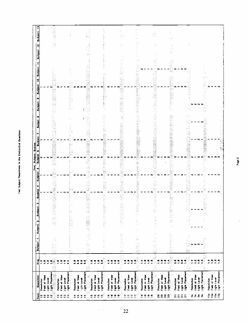
After each test, the subjects completed the End-to-End Questionnaires on viewing conditions. At theend of all the testing, the General Crosshair Questionnaires were completed. The subjects were asked torate each of these questions on a scale of 1 to 5 according to the categories listed in section 3.2.3.
3.2.1 End-to-End Questionnaires
The End-to-End Questionnaires were completed by the test subjects after each test. The questionnaireconsisted of the following four questions.
l° Resolution of the Target: How would you describe the resolution of the docking target relative towhat you would expect to see in order to accomplish a successful docking (consider limitedobstruction or shadowing caused by external crosshairs)?
2. Field of View: How would you describe the field of view through the camera relative to what youwould require to perform a successful docking?
3. Light Level: How would you describe the overall lighting levels relative to what you would requireto perform a successful docking (consider blooming)?
4. Light Placement: How would you describe the position of the lights relative to what you wouldrequire to perform a successful docking (consider shadowing)?
3.2.2 General Crosshair Questionnaires
The General Crosshair Questionnaires completed by the subjects at the end of all the test runs consistedof the following four questions.
1. Crosshair Cues: How would you describe the external crosshair as an aid to alignment of the target atapproach distances of 3 to 5 feet or greater?
2. Crosshair Cues: How would you describe the external crosshair as an aid to alignment of the target atapproach distances of 3 to 5 feet or less?
3. Electronic Overlay Cues: How would you describe the electronic overlay as an aid to alignment ofthe target at approach distances of 3 to 5 feet or greater?
4. Electronic Overlay Cues: How would you describe the electronic overlay as an aid to alignment ofthe target at approach distances of 3 to 5 feet or less?

3.2.3 Definition of Categories
The following categories were used to rate each of the questions. Each category was assigned anumerical designator, with 1 being the best and 5 being the worst.
1. Completely Acceptable--Design is adequate to perform docking. No changes are needed.
2. Reasonably Acceptable--Design is adequate to perform docking. Changes are desirable but notrequired for success.
3. Borderline--Docking could probably be performed, but conditions would make it uncertain and
possibly unsuccessful.
4. Reasonably Unacceptable--A successful docking is unlikely.
5. Completely Unacceptable--Docking would not be attempted because of safety concerns.
3.3 End-to-End Tests
Table 1 identifies the lighting conditions that were tested. The numbering system is unique, and test 18was deleted because it was a duplicate of a previous test. Note that the aft two payload bay floods were
always off because of thermal constraints with the Spacelab.
Section 4
Test Results
4.1 Presentation of the Data
The raw data from the questionnaires has been placed into matrix format and is enclosed in Appendix B.
4.2 Ranked Data
Table 2 shows averaged test subject responses to the end-to-end data from appendix B, ranked froml (best) to 5 (worst) for each of the four questions.
4.3 Photography and Video Recording
Each test run was recorded on video and a 5-minute summary video was made to demonstrate some of
the lighting conditions.. The video will be retained at JSC by Phil Mongan and Jay Legendre until thecompletion of STS-71. Photographs were also taken of the test setup, giving various vtews of theapproach as seen from the aft flight deck windows. (There are no photos of the view through thecenterline camera.) Photographs have been assigned NASA numbers ($93-037561 through $93-037571) and are retained in the JSC Image Sciences Division for use by NASA and NASA contractor
personnel.

Table 1. Test Matrix
Test Payload Bay HoodsRun 1 2 3 4 5 6
I off off off off off off
2 off on off on off off
3 on on on on off off
3a on on on on off off
4 off off off off off off
5 off off off off off off
6 off off off off off off
7 off off off off off off
8 off off off off off off
9 off off off off off off
l0 off off off off off off
11 off off off off off off
12 off off off off off off
13 off off Off Off Off Off
14 Off Off Off off Off Off
15 off off off off off off
15a off off off off off off
16 off off off off off off
17 on on on on off off
19" on on on on off off
20 on on on on off off
21 off on off on off off
50 off off on off off off
51 off off on on off off
52 off on on on off off
53 off on off on off off
54 on on off on off off
55 on on off off off off
56 on off off off off off
57 off on off off off off
OH
Docking
on
on
Bulkhead
Flood
on
on
on on
offon
on on
Oil on
on orl
on
on
on
on
on on
on on
on on
on on
on Off
on off
off off
off off
off off
Oil On
Oil 011
on off
off off
on off
on off
on off
on off
on off
on off
on off
on off
Port
Truss
on
on
on
off
off
onoff
on
on
on
off
onoff
onoffoff
off
off
on
on
on
off
on
on
on
on
on
on
on
on
Denotes test run at 24 vdc. or equivalent.
Stbd
Truss
on
on
on
off
off
off
on
on
on
on
on
off
on
off
off
off
off
off
on
on
on
off
on
on
on
on
on
on
on
on
Port Starboard
Centedine Centerline
orl on
on oll
on off
off off
On on
on on
on on
off off
on off
off on
off on
on off
on off
off on
off off
off on
on off.o
on on
off off
on on
off off
off off
off off
off off
off off
off off
off off
off off
off off
off off

Table 2. Relative Rankings of the Test Runs With Respect to Each Question
Resolution
Test Average
51 1.1
52 1.l
4 1.2
5 1.2
6 1.2
8 1.2
11 1.2
12 1.2
2 1.2
16 !.4
19 1.4
15a 1.4
50 1.4
53 1.4
54 1.4
55 1.4
57 1.4
3 1.4
3a 1.4
17 1.5
I 1.6
9 1.6
20 1.6
56 1.7
10 1.8
13 1.8
15 1.8
21 2.0
7 2.8
14 5.0
Field of View Light Level Light Placement
Test Average Test Average Test Average
5 1.0
6 1.0
8 1.0
9 1.0
10 1.0
11 1.0
12 1.0
13 1.0
15 1.0
16 ! .0
17 i.0
19 1.0
20 1.0
21 1.0
15a 1.0
51 i.0
52 1.0
53 1.0
54 1.0
57 1.0
1 1.1
2 1.1
50 1.1
55 1.1
56 1.1
4 1.2
3 1.2
3a 1.2
7 1.3
14 5.0
6 1.0
II 1.0
16 1.0
19 1.0
4 1.2
5 t.2
8 1.2
12 1.2
15a 1.2
54 1.3
I 1.3
51 1.4
52 1.4
3 1.4
53 1.5
55 1.5
2 1.6
10 1.6
13 1.6
17 1.0
52 1.1
4 1.3
3a 1.3
54 1.4
20 1.4
5 1.5
2 1.6
3 1.6
16 1.6
19 1.6
21 1.6
51 1.6
6 1.7
50 1.7
53 1.7
55 1.7
11 1.8
12 1.8
15a 1.8
56 1.9
57 ! .9
1 i.9
8 2.0
9 2.4
10 2.4
13 2.4
15 2.6
7 2.8
14 5.0
15 1.6
20 1.6
57 1.6
17 1.8
9 1.8
50 1.9
3a 1.9
56 2.0
7 2.7
21 2.8
14 5.0
Section 5
Analysis of the Data
Establishing an acceptable cutoff ranking of 2.0 based on the categories in section 3.2.3 will ensurevisibility conditions sufficient for a successful docking. A ranking greater than 2.0 would introducesome amount of risk into the docking, and success could not be guaranteed.
Each test should be considered a docking. If any one of the four questions for a particular test is ranked
greater than the 2.0 cutoff, that docking might have been unsuccessful. On table 2, a line has beendrawn in the column for each question so that everything from 1.0 through 2.0 falls above the line and
everything greater than 2.0 falls below the line.
It should be noted that test 14 was an extreme case to simulate the effects of having only the overhead
docking light. This is not indicative of any reasonable failure scenario, because a docking would notusually be attempted with only one operational light.
9

5.1 Field of View
Responses to the field of view question were the most consistent, with the lowest collective averagerankings. This consistency was expected because the field of view was fixed for this test through the 4-inch hatch window. The low average indicates that the field of view through the 4-inch hatch window,with the camera lens about 2.75 inches below the window, is adequate.
5.2 Resolution
The resolution also scored consistently good except in two test runs: test 14, which was the extreme
case, and test 7, which had both centedine lights turned off and all of the payload bay flood lights turnedoff. In test 7, as the Orbiter and Mir neared contact, the lighting levels became so low that the resolution
became grainy and degraded to a level which would have introduced an element of risk to a successfuldocking.
The resolution question was designed to determine if the optical quality of the hatch window and thecamera system were adequate to support the docking. The consistently good scores indicate that thewindow and camera system provide adequate resolution to perform a successful docking.
5.3 Light Levels
Three tests were ranked greater than the 2.0 threshold in the lighting level category. Since low lightinglevel degrades the resolution, if the windows and camera system were good, the lighting levels and ..resolution answers should show some consistency. As they were on the resolution question, tests 7 and14 are greater than the adequate threshold. Additionally, test 21 was graded greater than a 2.0. Notethat test 21 was borderline in the resolution also, which emphasized the consistency between lightinglevels and resolution.
The reflection of the lights off the unpainted docking target bolts was noticeable, but not a problem for
the docking. Additionally, there were no light reflection problems off the laser reflector. Again, theconsistently good scores indicate that the lighting levels are adequate to perform a successful docking.
5.4 Light Placement
It is obvious from the rankings shown in table 2 that the placement of the lights is important to the
acceptability of the design. Six tests were scored greater than a 2.0, largely because of unacceptableshadowing under the various failed light conditions. In some of these cases, specifically failures of onecenterline light, the shadow of the docking target standoff cross looks very similar to the standoff cross
itself. The only way to distinguish the two is by the white dot in the middle of the standoff cross.Additionally, the shadow can obscure the tips of the cross, or the alignment hash marks on the base ofthe target. Failures of other lights such as the truss lights or payload bay floods create shadowing, butnot to an unacceptable level.
The shadows can be dealt with by providing light in locations which will offset them. Assuming overalllight levels are acceptable, this can be accomplished by operational workarounds. For example, if aparticular light failure creates a bad shadowing effect, other lights could be turned off or on to alleviatethis problem. Therefore, the existing light placement is acceptable for performance of a successful
docking.
10

5.5 Unsuccessful Runs
The potentially unsuccessful docking runs are summarized in table 3. The test runs are ranked accordingto their worst score of each of the four questions, because that is the score which would cause theunsuccessful docking.
Table 3
Ranking of Potentially Unsuccessful DockingsAccording to their Worst Score of the 4 Questions
Test Average2.4
10 2.4
13 2.4
15 2.6
7 2.8
21 2.8
14 5.0
It should be noted that only one of the test runs failed totally with a score of 5. This test was an extreme
case designed to show the importance of the overhead docking light. As can be seen from the score, theoverhead docking light does not provide much light on the target by itself.
Scores on all other runs averaged between 2.0 and 3.0, indicating that the docking probably could have
been performed. These runs all have one thing in common; the port centerline light is failed. A portcenterline light failure casts a shadow to the right as viewed on the monitor, which can obscure the tip ofthe target cross and the alignment hash marks on the target. A failed port centerline light tended tocreate undesirable shadows when the Mir and Shuttle were close to docking, whereas a failed starboard
centerline light created undesirable shadows at the farther distances. This shadow can be eliminated byturning off the opposite centerline light, but as can be seen in test 7 results, the lighting levels become solow that the scores remain in the 2.0 to 3.0 range. These resulting low light levels can be alleviated byturning on at least one payload bay flood light, as was done in tests 50 through 57.
To recap, if a port centerline light fails and at least one payload bay flood is on, the starboard centerlinelight can be turned off, and the lighting levels and shadowing will be acceptable, as was shown in testrun 50. If this procedure is used, tests 9, 10, 13, and 7 could be moved up to the adequate threshold.The only remaining questionable tests are 15, 21, and 14, which axe extreme cases and not indicative ofsituations we would expect to see during a docking.
It was the general feeling of the test subjects that the existing lighting configuration provides enoughlight, and if individual switching is available, enough flexibility to accommodate a successful docking.
5.6 External Crosshairs
The raw data from the General Crosshair Questions is presented in appendix B. The data are averagedand ranked in table 4. The four questions referred to in this table are given in section 3.2.2.
It can be seen that the external crosshairs are more effective for target alignment at close distances than
at far distances, but they are not the preferred method of alignment in either case. The reason for this isthat through most of the approach, in order to bring both the crosshair center ring and the target in focus
11

at the same time, the camera has to be zoomed out so far that the image of the target is smaller than whatis preferred by the test subject.
The external crosshairs also caused a slight blurring of the image when both centerline lights were on,but not to the extent that they would interfere with a successful docking. This blurring was not apparentwith both centerline lights turned off. The external crosshairs did, however, perform well for aligning
the camera prior to the testing.
Table 4
General Crosshair Questions Ranking
Question1. External X-hair, > 5 ft.
Avg2.9
2. External X-hair, < 5 ft. 2.1
3. Electronic X-hair, > 5 ft. 1.44. Electronic X-hair, < 5 ft. 1.1
5.7 Electronic Crosshairs
The data from the electronic crosshairs are also presented in table 4. These clearly act as an aid toalignment of the target at all distances. It should be noted that two different electronic crosshairs areavailable to the crew: green and white. The green ones are actually the true center of the image, but thewhite ones are very close to the same location.
The test subjects felt that the green crosshairs were too bright and too thick. If they are to be used theyshould be dimmable and thinner. The white crosshairs, however, worked very well, although some
subjects would have preferred these be dimmable also.
5.8 Overlay
Some subjects thought it would be beneficial to place a grease pencil mark on the monitor screen toindicate the center, and turn off the electronic crosshairs altogether. The monitor screen, however, iscoated with an anti-static film which is easily rubbed off, therefore preventing the use of a grease pencil.An overlay was taped to the front of the monitor to simulate this concept, which appeared to work wellfor some of the subjects.
Section 6Conclusions and Recommendations
The conclusions and recommendations address the specific objectives: resolution, field of view, lightplacement, light levels, failed lights, the need for docking adapter lights, and camera alignment system.
6.1 Resolution
The resolution of the system is adequate as it is. The window provides sufficient clarity and does notneed to be replaced with an optical quality window. The resolution of the CTVC system is also
adequate.
12

6.2 Field of View
The field of view through the 4-inch hatch window was adequate with the camera lens placed about 2.75inches below the window. No changes are required to the systems' field of view.
6.3 Light Placement
The placement of the lights was the most important factor in determining the success of the docking.Some failed light conditions cause shadowing which can obscure important alignment cues. This can bealleviated by subsequently turning on or off other lights which will have the effect of eliminating orwashing out a particular shadow. The test subjects felt that light diffusion in ground testing causesshadows to not be as distinct as they would be in space. Consequently, bad shadows on the groundwould be even worse in space. Based on this, it is important that the flight deck crew have individualswitching capability for the lights which will be used in the docking to offer maximum flexibility ofshadow management. No changes in the placement of lights are recommended.
6.4 Light Levels
The light levels are adequate as designed to perform a successful docking. The centerline camera does agreat job compensating for low light levels. In general, there is good illumination of the docking target,and blooming from the unpainted stainless steel bolts or target laser reflector does not create a problem.The standard Orbiter flashlight was used from the aft flight deck, but the Mir forward petal blocked thelight beam from reaching the target, rendering the flashlight useless for target illumination. No changesin the light levels or number of lights are recommended.
6.5 Failed Lights
Failed light conditions can impact lighting levels and cause shadowing. The system as designed shouldbe able to sustain reasonable light failures and still provide enough light to complete the docking. Somelight failures, especially a failure of one of the centerline lights, will cause adverse shadowing. A failedport centerline light tended to create undesirable shadows when the Mir and Shuttle were close todocking, and a failed starboard centerline light created undesirable shadows at the farther distances. Inthese adverse shadowing cases, individual switching can be used to provide an acceptable lightingenvironment. Failure of both centerline lights will not be a problem if at least one payload bayfloodlight is working. Procedures for light management will be crew dependent and should be
developed during the simulated docking runs for the mission.
6.6 Docking Adapter Lights
Some subjects preferred the docking adapter lights on and some preferred them off. Most, though, didnot like one on and one off. Either way, adequate light exists as long as at least one payload bay flood is
operational. It is recommended that the docking adapter lights be retained to offer maximum flexibilityto deal with other light failures and user preference.
6.7 Alignment Crosshairs
Most subjects felt that the green electronic crosshairs were too bright and thick. The white crosshairsperformed well, but according to the CTVC experts, were not exactly in the center of the image.
13

Theexternalcrosshairsperformwell in aligningthecamera.Theexternalcrosshairs,however,werenotthepreferredmethodof alignipg theOrbiterwith thetargeton theMir. Additionally, theexternalcrosshairscausedaslight blurring of the imagewith bothcenterlinelights on,butnot to theextentthattheywould interferewith thesuccessof thedocking.
No specificrecommendationswill begivenrelativeto whichcrosshairsshould be used because this islargely operator dependent. The most popular alignment aids were the white crosshair or an overlay.The green crosshairs should be made dimmable if their use is expected. Also, before procedures aredeveloped, further investigation is needed to determine if the white crosshairs are accurate enough andare interchangeable with the green crosshairs throughout the camera alignment and target alignmentphases of flight.
Adequate alignment mechanisms certainly exist, and it should be at the discretion of the crew andprocedures developers to determine the actual method of alignment that will be used.
14

Appendix A
Participating and Supporting Organizations
15


Participating Organizations
The following organizations participated in running and/or planning this test.
Flight Crew Operations Directorate/CA - Input to test configuration and procedures, and flightcrew contacts
Astronaut Office/CB - Input to test configuration and procedures
Flight Design and Dynamics Division/DM - Operations input to test configuration and
procedures
Tracking and Communications Division/EE - Camera equipment
Flight Data Systems Division/EK - Lighting equipment
Rockwell - Building the docking adapter and Mir interface mockups, and providing drawings to
support camera and lighting identification
Flight Crew Support Division/SP - Mockup and trainer support, lighting expertise, miscellaneous
hardware support, and Test Director
Cargo Engineering Officefl'J - Inputs on Mir configuration. Provide Mix docking target
Orbiter Avionics Systems Office/VG - Project Office contact for overall test --
Flight Support Equipment OfficefVP - Contract authority over Rockwell-supplied hardware andsupport to overall test configuration
f
Test Support Personnel
The following personnel were responsible for various aspects of planning, conducting, and reportingassociated with the test. Phone numbers are in area code 713 unless otherwise noted.
Name
SP3/Phil MonganVG/Tom Grace
VG/Stu McClungVP5/Anselmo Lozano
VP4/Ragan EdmistonRI, ZC20/Bob GrooRI, FB-94/Chuck LyttleRI, FB-94/Emmett ShepherdSP5/David RaySP5/Dennis McClain
SP5/John MurphySP5/David WoodSP5/Steve Elliott
SP5/Barry KazilasEE2/Wendell RowanEE2/Gene BeckEK2/Diana Schuler
FunctionTest Director
Project Office contactProject Office contactDocking AdaptersProject Office contactDocking AdaptersRockwell Cameras
Rockwell LightingFFT & 9a OpsMechanical TechElectrical TechMechanical Tech
Technician SupportMechanical Tech
TV & Video SystemTV & Video SystemLighting Hardware
Phone483-2137483-3431483-3015483-6339483-0956338-6319
(310)922-0683(310)922-0683483-5928483-6329483-2174483-2131483-2148483-6334483-0177483-0182483-1512
17 _G PAGE BLANK NOT F_MED

SP3/Chuck WheelwrightSP3/Jennifer Toole
SP3/Jay LegendreSP3/Carlos SampaioSP3/Terry FlemmingTJ2/Greg LangeDM43FLynda GavinCA3/Bill EhrenstromCA4/Russ FillerCB/Carl Meade
Lighting Lab SupportLighting Lab SupportAlignment CrosshairsAlignment CrosshairsAlignment CrosshairsDocking TargetRendezvous OpsCrew SupportCrew SupportAstronaut Office
333-7815333-7611483-3697483-9719483-6044483-1176483-8007244-8530244-8621244-8701
Test Subjects
The following people were used as test subjects to evaluate the proposed design. The subjects all havesignificant experience in understanding what is important to see on the monitor in order to perform asuccessful docking.
Nsllle
SP3/Jay LegendreDM4/Lynda GavinDM3Jeannette Gillogly
C87/Pete SpeharB 14/Julia ChuCB/Carl MeadeCB/Kevin Chilton
CB/Steve NagelCB/Norm ThagardCB/Brent JettCB/Dave Walker
CB/Jim BagianCB/Don McMonagleCB/Frank Culbertson (observer only)
Function
Man-SystemsRendezvous OpsRendezvous and Prox Ops
Working Group (RPOWG)RPOWGRPOWGAstronautAstronautAstronautAstronautAstronautAstronautAstronautAstronautAstronaut
2__
18

Appendix B
Raw Data
19


w
6
o
!|c_
2!P_ PAC..,E Efl.A_iK I'JOT F_MED
J
o
.I0.
a,e"
!ip.-
u
!2A_
(_][i iili
e_
° iiiii!i!_
i,_i_
I
p,.. i: i!
H •
i!?
_I i_:_
_ _ P (_v! ¸
i___i_
H
H
o o m _" o o o o_ • o o o q" o o e :_ _ o am, oii_ qP o o us::: o o o o o o o'_i _ eq • _,_i:ii _ o e,_ o
,.: • ,.: ,._.......
L 22

0
w
o
!
n-
23

Jic_
8
i,
o
i
...- o o
,_ • •
°
P
24


REPORT DOCUMENTATION PAGE I _ormA_prov,_OM8_o 070_-0,8a
PuIolic feOor¢lng _ourden for this collection of mfofmlltlOn *$ estimited to avef_jle 1 hour per respond, inclu¢hn(J the time for reviewlncj instructions, tellrcht¢_ e=i_ting data _Ources. gather,ng andmalntamtrwg the data needed, and comtlWetlng and reviewing the collection of _nformatlon Sen_i comments regircling tl_t$ iDurden e._ttmlte Of any other asil_c't of this colic(lion of iMtorn_attonincluding tugcJeStlon$ for reducing this bu_, tO Wishin_on Megd¢lUafters ¢.erv*ce_, O,rc,_-torate for InformatiOn O_eritlon$ _ln(I ReDor_. 1215 Je'_fer,_on Darts HighwBy, Su,te 1204 _rhngton v-_22202-4302, and ¢Othe Office of Manacjemeflt and Budget, P=l_erwor_ RedtJCIlOn Prolet't (0704-0188). Washington. DE 2050]
I AGENCY USE ONLY (Leave blank) ; ,REPORT DATE 3 REPORT TYPE AND DATES COVEREDDecember 1993 Technical Memorandum
4 TITLE AND SUBTITLE S. FUNDING NUMBERS
Orbital Docking System Centerline Color Television CameraSystem Test
6. AUTHOR(S)
Philip T. Rongan
7. PERFORMINGORGANIZATIONNAME(S)ANDADDRESS(ES)Lyndon B. Johnson Space CenterFlight Crew Support Division
Houston, TX 77058
9. SPONSORINGIMONITORINGAGENCYNAME(S)ANOADDRESS(ES)National Aeronautics and Space Administration
Washington, D.C. 20546-001
8. PERFORMING ORGANIZATIONREPORT NUMBER
S-743
10. SPONSORING/MONITORINGAGENCY REPORT NUMBER
NASA-TM-104783
11. SUPPLEMENTARY NOTES
12aDISTRIBUTION/AVAII.ABILIT_'STATEMENT
Unclassified/Publicly AvailableNational Technical Information Service
5285 Port Royal Road
Springfield, VA 22161(703) 487-4600 Subject Category 18
12b. DISTRIBUTION _.ODE
1 3. ABSTRACT (Maximum 200wOrds)
A series of tests was run to verify that the design of the centerltne color televisioncamera (CTVC) system is adequate optically for the STS-71 Space Shuttle Orbiter dockingmission with the Rir space station. In each test, a mockup of the Mtr consisting ofhatch, docking mechanism, and docking target was positioned above the Johnson SpaceCenter's full fuselage trainer, which simulated the Orbiter with a mockup of theexternal atrlock and docking adapter. Test subjects viewed the docking target throughthe CTVC under 30 different lighting conditions and evaluated target resolution, fieldof view, light levels, light placement, and methods of target alignment. Test resultsindicate that the proposed design will provide adequate visibility through the
centerline camera for a successful docking, even with a reasonable number of light
failures. It is recommended that the flight deck crew have individual switching
capability for docking lights to provide maximum shadow management and that centerline
lights be retained to deal with light failures and user preferences. Procedures for
light management should be developed and target alignment aids should be selected during
simulated docking runs.
14 SUBJECTTERMSSpacecraft Docking, Mir Space Station, Spacecraft Television,
Viewing, Alignment, Target Recognition, Light Sources, VisualTasks
7 oFSECURtTYCLASSIFICATtONREPORT[18. oFSECURITYCLASStFtCATIONTHISPAGE IUnclassified Unclassified Unclassified
Stanc_arcl Form 298 (Rev 2-8g)Prescribed bv ANSI Std 239-18298-102
19 SECURITY CLASSIFICATIONOF ABSTRACT
15 NUMBEROF PAGES
25
16 PRICE CODE
20 LIMITATION OF ABSTRACT
UL