oracle solaris administration devices and file systems system /solaris/solaris11/oracle... ·...
TRANSCRIPT

Oracle® Solaris Administration: Devices andFile Systems
Part No: 821–1459–12February 2012

Copyright © 2004, 2012, Oracle and/or its affiliates. All rights reserved.
This software and related documentation are provided under a license agreement containing restrictions on use and disclosure and are protected by intellectualproperty laws. Except as expressly permitted in your license agreement or allowed by law, you may not use, copy, reproduce, translate, broadcast, modify, license,transmit, distribute, exhibit, perform, publish or display any part, in any form, or by any means. Reverse engineering, disassembly, or decompilation of this software,unless required by law for interoperability, is prohibited.
The information contained herein is subject to change without notice and is not warranted to be error-free. If you find any errors, please report them to us in writing.
If this is software or related documentation that is delivered to the U.S. Government or anyone licensing it on behalf of the U.S. Government, the following notice isapplicable:
U.S. GOVERNMENT RIGHTS. Programs, software, databases, and related documentation and technical data delivered to U.S. Government customers are"commercial computer software" or "commercial technical data" pursuant to the applicable Federal Acquisition Regulation and agency-specific supplementalregulations. As such, the use, duplication, disclosure, modification, and adaptation shall be subject to the restrictions and license terms set forth in the applicableGovernment contract, and, to the extent applicable by the terms of the Government contract, the additional rights set forth in FAR 52.227-19, CommercialComputer Software License (December 2007). Oracle America, Inc., 500 Oracle Parkway, Redwood City, CA 94065.
This software or hardware is developed for general use in a variety of information management applications. It is not developed or intended for use in any inherentlydangerous applications, including applications that may create a risk of personal injury. If you use this software or hardware in dangerous applications, then you shallbe responsible to take all appropriate fail-safe, backup, redundancy, and other measures to ensure its safe use. Oracle Corporation and its affiliates disclaim anyliability for any damages caused by use of this software or hardware in dangerous applications.
Oracle and Java are registered trademarks of Oracle and/or its affiliates. Other names may be trademarks of their respective owners.
Intel and Intel Xeon are trademarks or registered trademarks of Intel Corporation. All SPARC trademarks are used under license and are trademarks or registeredtrademarks of SPARC International, Inc. AMD, Opteron, the AMD logo, and the AMD Opteron logo are trademarks or registered trademarks of Advanced MicroDevices. UNIX is a registered trademark of The Open Group.
This software or hardware and documentation may provide access to or information on content, products, and services from third parties. Oracle Corporation andits affiliates are not responsible for and expressly disclaim all warranties of any kind with respect to third-party content, products, and services. Oracle Corporationand its affiliates will not be responsible for any loss, costs, or damages incurred due to your access to or use of third-party content, products, or services.
Ce logiciel et la documentation qui l’accompagne sont protégés par les lois sur la propriété intellectuelle. Ils sont concédés sous licence et soumis à des restrictionsd’utilisation et de divulgation. Sauf disposition de votre contrat de licence ou de la loi, vous ne pouvez pas copier, reproduire, traduire, diffuser, modifier, breveter,transmettre, distribuer, exposer, exécuter, publier ou afficher le logiciel, même partiellement, sous quelque forme et par quelque procédé que ce soit. Par ailleurs, il estinterdit de procéder à toute ingénierie inverse du logiciel, de le désassembler ou de le décompiler, excepté à des fins d’interopérabilité avec des logiciels tiers ou tel queprescrit par la loi.
Les informations fournies dans ce document sont susceptibles de modification sans préavis. Par ailleurs, Oracle Corporation ne garantit pas qu’elles soient exemptesd’erreurs et vous invite, le cas échéant, à lui en faire part par écrit.
Si ce logiciel, ou la documentation qui l’accompagne, est concédé sous licence au Gouvernement des Etats-Unis, ou à toute entité qui délivre la licence de ce logicielou l’utilise pour le compte du Gouvernement des Etats-Unis, la notice suivante s’applique:
U.S. GOVERNMENT RIGHTS. Programs, software, databases, and related documentation and technical data delivered to U.S. Government customers are"commercial computer software" or "commercial technical data" pursuant to the applicable Federal Acquisition Regulation and agency-specific supplementalregulations. As such, the use, duplication, disclosure, modification, and adaptation shall be subject to the restrictions and license terms set forth in the applicableGovernment contract, and, to the extent applicable by the terms of the Government contract, the additional rights set forth in FAR 52.227-19, CommercialComputer Software License (December 2007). Oracle America, Inc., 500 Oracle Parkway, Redwood City, CA 94065.
Ce logiciel ou matériel a été développé pour un usage général dans le cadre d’applications de gestion des informations. Ce logiciel ou matériel n’est pas conçu ni n’estdestiné à être utilisé dans des applications à risque, notamment dans des applications pouvant causer des dommages corporels. Si vous utilisez ce logiciel ou matérieldans le cadre d’applications dangereuses, il est de votre responsabilité de prendre toutes les mesures de secours, de sauvegarde, de redondance et autres mesuresnécessaires à son utilisation dans des conditions optimales de sécurité. Oracle Corporation et ses affiliés déclinent toute responsabilité quant aux dommages causéspar l’utilisation de ce logiciel ou matériel pour ce type d’applications.
Oracle et Java sont des marques déposées d’Oracle Corporation et/ou de ses affiliés. Tout autre nom mentionné peut correspondre à des marques appartenant àd’autres propriétaires qu’Oracle.
Intel et Intel Xeon sont des marques ou des marques déposées d’Intel Corporation. Toutes les marques SPARC sont utilisées sous licence et sont des marques ou desmarques déposées de SPARC International, Inc. AMD, Opteron, le logo AMD et le logo AMD Opteron sont des marques ou des marques déposées d’Advanced MicroDevices. UNIX est une marque déposée d’The Open Group.
Ce logiciel ou matériel et la documentation qui l’accompagne peuvent fournir des informations ou des liens donnant accès à des contenus, des produits et des servicesémanant de tiers. Oracle Corporation et ses affiliés déclinent toute responsabilité ou garantie expresse quant aux contenus, produits ou services émanant de tiers. Enaucun cas, Oracle Corporation et ses affiliés ne sauraient être tenus pour responsables des pertes subies, des coûts occasionnés ou des dommages causés par l’accès àdes contenus, produits ou services tiers, ou à leur utilisation.
120305@25097

Contents
Preface ...................................................................................................................................................17
1 Managing Removable Media (Overview) ........................................................................................21What's New in Removable Media? .................................................................................................... 21
Changes and Improvements to Removable Media Management .......................................... 21Where to Find Managing Removable Media Tasks ......................................................................... 24Removable Media Features and Benefits .......................................................................................... 25Comparison of Manual and Automatic Mounting ......................................................................... 25Overview of Accessing Removable Media ........................................................................................ 26
2 Managing Removable Media (Tasks) ...............................................................................................27Managing Removable Media (Task Map) ........................................................................................ 27Preparing Removable Media .............................................................................................................. 28
Removable Media Considerations ............................................................................................. 28▼ How to Load Removable Media ................................................................................................. 29▼ How to Format a Diskette (rmformat) ....................................................................................... 30▼ How to Create a File System on Removable Media .................................................................. 31▼ How to Create a File System on a DVD-RAM .......................................................................... 32▼ How to Check a File System on Removable Media .................................................................. 32▼ How to Repair Bad Blocks on Removable Media ..................................................................... 33
Applying Read or Write Protection and Password Protection to Removable Media .......... 33▼ How to Enable or Disable Write Protection on Removable Media ........................................ 33▼ How to Enable or Disable Read or Write Protection and Set a Password on Removable
Media ............................................................................................................................................. 34
3 Accessing Removable Media (Tasks) ................................................................................................35Accessing Removable Media (Task Map) ......................................................................................... 35
3

Accessing Removable Media .............................................................................................................. 36Using Removable Media Names ................................................................................................ 36Guidelines for Accessing Removable Media Data ................................................................... 36
▼ How to Add a New Removable Media Drive ............................................................................ 36▼ How to Disable or Enable Removable Media Services ............................................................. 37▼ How to Access Information on Removable Media .................................................................. 38▼ How to Copy Information From Removable Media ................................................................ 38▼ How to Determine If Removable Media Is Still in Use ............................................................ 39▼ How to Eject Removable Media .................................................................................................. 39
Accessing Removable Media on a Remote System (Task Map) ..................................................... 40▼ How to Make Local Media Available to Other Systems ........................................................... 40▼ How to Access Removable Media on Remote Systems ............................................................ 41
4 Writing CDs and DVDs (Tasks) ........................................................................................................... 43Working With Audio CDs and Data CDs and DVDs ..................................................................... 43
CD/DVD Media Commonly Used Terms ................................................................................ 44Writing CD and DVD Data and Audio CDs .................................................................................... 45
Restricting User Access to Removable Media With RBAC ..................................................... 46▼ How to Restrict User Access to Removable Media With RBAC ............................................. 46▼ How to Identify a CD or DVD Writer ....................................................................................... 47▼ How to Check the CD or DVD Media ....................................................................................... 47
Creating a Data CD or DVD ....................................................................................................... 48▼ How to Create an ISO 9660 File System for a Data CD or DVD ............................................. 48▼ How to Create a Multi-Session Data CD ................................................................................... 49
Creating an Audio CD ................................................................................................................. 51▼ How to Create an Audio CD ....................................................................................................... 51▼ How to Extract an Audio Track on a CD ................................................................................... 52▼ How to Copy a CD ....................................................................................................................... 53▼ How to Erase CD-RW Media ..................................................................................................... 54
5 Managing Devices (Overview/Tasks) ...............................................................................................55What's New in Device Management? ................................................................................................ 56
Customizing Driver Configuration ........................................................................................... 56Solaris PCI Resource Manager ................................................................................................... 56New InfiniBand Administration Features ................................................................................. 57
Contents
Oracle Solaris Administration: Devices and File Systems • February 20124

New InfiniBand Diagnostic Tools and Commands ................................................................. 57New Ethernet Over InfiniBand Devices .................................................................................... 57New Hot Plugging Features ........................................................................................................ 57Device Naming Enhancements .................................................................................................. 58Support for PCI Express (PCIe) ................................................................................................. 58
Where to Find Additional Device Management Tasks ................................................................... 59Managing Devices in the Oracle Solaris OS ..................................................................................... 60
Identifying Device Support ......................................................................................................... 60About Device Drivers .................................................................................................................. 60Automatic Configuration of Devices ......................................................................................... 61Displaying Device Configuration Information ........................................................................ 63Resolving Faulty Devices ............................................................................................................. 67
Adding a Peripheral Device to a System ........................................................................................... 69▼ How to Add a Peripheral Device ................................................................................................ 69▼ How to Add a Device Driver ....................................................................................................... 70
Accessing Devices ................................................................................................................................ 71How Device Information Is Created .......................................................................................... 71How Devices Are Managed ......................................................................................................... 72Device Naming Conventions ..................................................................................................... 72Logical Disk Device Names ........................................................................................................ 73Logical Tape Device Names ........................................................................................................ 75Logical Removable Media Device Names ................................................................................. 76
6 Dynamically Configuring Devices (Tasks) .......................................................................................77Dynamic Reconfiguration and Hot-Plugging .................................................................................. 77
Attachment Points ....................................................................................................................... 79Detaching PCI or PCIe Adapter Cards ...................................................................................... 80Attaching PCI or PCIe Adapter Cards ....................................................................................... 81PCIe Hot-Plugging With the (hotplug) Command ................................................................ 81
SCSI Hot-Plugging With the cfgadm Command (Task Map) ....................................................... 83SCSI Hot-Plugging With the cfgadm Command ............................................................................. 84
▼ How to Display Information About SCSI Devices ................................................................... 84▼ How to Unconfigure a SCSI Controller ..................................................................................... 85▼ How to Configure a SCSI Controller ......................................................................................... 85▼ How to Configure a SCSI Device ................................................................................................ 86
Contents
5

▼ How to Disconnect a SCSI Controller ....................................................................................... 86▼ SPARC: How to Connect a SCSI Controller ............................................................................. 87▼ SPARC: How to Add a SCSI Device to a SCSI Bus ................................................................... 88▼ SPARC: How to Replace an Identical Device on a SCSI Controller ....................................... 89▼ SPARC: How to Remove a SCSI Device .................................................................................... 90
Troubleshooting SCSI Configuration Problems ...................................................................... 91▼ How to Resolve a Failed SCSI Unconfigure Operation ........................................................... 93
PCI or PCIe Hot-Plugging With the cfgadm Command (Task Map) ........................................... 93PCI or PCIe Hot-Plugging With the cfgadm Command ................................................................ 94
PCIe LED Indicator Behavior ..................................................................................................... 94▼ How to Display PCI Slot Configuration Information ............................................................. 94▼ How to Remove a PCI Adapter Card ......................................................................................... 96▼ How to Add a PCI Adapter Card ................................................................................................ 97
Troubleshooting PCI Configuration Problems ....................................................................... 99SATA Hot-Plugging With the cfgadm Command ......................................................................... 100
▼ How to Unconfigure a SATA Device ....................................................................................... 100▼ How to Configure a SATA Device ............................................................................................ 101
Reconfiguration Coordination Manager (RCM) Script Overview ............................................. 101What Is an RCM Script? ............................................................................................................ 102What Can an RCM Script Do? ................................................................................................. 102How Does the RCM Script Process Work? ............................................................................. 102
RCM Script Tasks .............................................................................................................................. 103Application Developer RCM Script (Task Map) .................................................................... 103System Administrator RCM Script (Task Map) ..................................................................... 104Naming an RCM Script ............................................................................................................. 104Installing or Removing an RCM Script ................................................................................... 105
▼ How to Install an RCM Script ................................................................................................... 105▼ How to Remove an RCM Script ............................................................................................... 105▼ How to Test an RCM Script ...................................................................................................... 106
Tape Backup RCM Script Example .......................................................................................... 106
7 Using USB Devices (Overview) .........................................................................................................111What's New in USB Devices? ........................................................................................................... 112
USB Interface Association Descriptor Support ...................................................................... 112EHCI Isochronous Transfer Support ...................................................................................... 112
Contents
Oracle Solaris Administration: Devices and File Systems • February 20126

USB Device Hotpluggable Behavior ........................................................................................ 112x86: Support for USB CDs and DVDs in GRUB-Based Booting .......................................... 113USB Virtual Keyboard and Mouse Support ............................................................................ 113
Oracle Solaris Support for USB Devices ......................................................................................... 114Overview of USB Devices ................................................................................................................. 115
Commonly Used USB Acronyms ............................................................................................ 115USB Bus Description ................................................................................................................. 115
About USB in the Oracle Solaris OS ................................................................................................ 120USB 2.0 Features ......................................................................................................................... 120USB Keyboards and Mouse Devices ........................................................................................ 122USB Host Controller and Hubs ................................................................................................ 123Guidelines for USB Cables ........................................................................................................ 124
8 Using USB Devices (Tasks) ................................................................................................................127Managing USB Devices in the Oracle Solaris OS (Roadmap) ...................................................... 127Using USB Mass Storage Devices (Task Map) ............................................................................... 128Using USB Mass Storage Devices .................................................................................................... 129
Using USB Diskette Devices ..................................................................................................... 130Using Non-Compliant USB Mass Storage Devices ............................................................... 131Hot-Plugging USB Mass Storage Devices ............................................................................... 131Preparing to Use a USB Mass Storage Device ......................................................................... 135
▼ How to Display USB Device Information ............................................................................... 135▼ How to Create a File System on a USB Mass Storage Device ................................................ 136▼ How to Modify Partitions and Create a PCFS File System on a USB Mass Storage
Device .......................................................................................................................................... 138▼ How to Create a Solaris Partition and Modify the Slices on a USB Mass Storage Device .. 141▼ How to Mount or Unmount a USB Mass Storage Device ..................................................... 143
Troubleshooting Tips for USB Mass Storage Devices ........................................................... 144Disabling Specific USB Drivers ................................................................................................ 145
▼ How to Disable Specific USB Drivers ...................................................................................... 145▼ How to Remove Unused USB Device Links ........................................................................... 146
Using USB Audio Devices (Task Map) ........................................................................................... 146Using USB Audio Devices ................................................................................................................ 147
Hot-Plugging Multiple USB Audio Devices ........................................................................... 148▼ How to Add USB Audio Devices .............................................................................................. 148
Contents
7

▼ How to Identify Your System's Primary Audio Device ......................................................... 148▼ How to Change the Primary USB Audio Device .................................................................... 149
Troubleshooting USB Audio Device Problems ...................................................................... 149Hot-Plugging USB Devices With the cfgadm Command (Task Map) ........................................ 150
Hot-Plugging USB Devices With the cfgadm Command ..................................................... 151▼ How to Display USB Bus Information (cfgadm) .................................................................... 151▼ How to Unconfigure a USB Device .......................................................................................... 152▼ How to Configure a USB Device .............................................................................................. 153▼ How to Logically Disconnect a USB Device ........................................................................... 153▼ How to Logically Connect a USB Device ................................................................................ 154▼ How to Logically Disconnect a USB Device Subtree ............................................................. 154▼ How to Reset a USB Device ....................................................................................................... 155▼ How to Change the Default Configuration of a Multi-Configuration USB Device ........... 155
9 Using InfiniBand Devices (Overview/Tasks) ..................................................................................157Overview of InfiniBand Devices ...................................................................................................... 157
InfiniBand Software Packages .................................................................................................. 159Dynamically Reconfiguring IB Devices (Task Map) ..................................................................... 159Dynamically Reconfiguring IB Devices (cfgadm) ......................................................................... 161
Unconfiguring IB Device Considerations .............................................................................. 162▼ How to Display IB Device Information ................................................................................... 162▼ How to Unconfigure an IB Port, HCA_SVC, or a VPPA Device .......................................... 164▼ How to Configure a IB Port, HCA_SVC, or a VPPA Device ................................................. 164▼ How to Unconfigure an IB Pseudo Device .............................................................................. 165▼ How to Configure an IB Pseudo Device .................................................................................. 165▼ How to Display Kernel IB Clients of an HCA ......................................................................... 166▼ How to Dynamically Reconfigure an HCA With Active EoIB Devices ............................... 166▼ How to Reconfigure and Restore an EoIB Interface After Hot Removal ............................. 167
Configuring an IB HCA ............................................................................................................ 168▼ How to Update the IB P_key Tables ......................................................................................... 168▼ How to Display IB Communication Services ......................................................................... 169▼ How to Add a VPPA Communication Service ....................................................................... 169▼ How to Remove an Existing IB Port, HCA_SVC, or a VPPA Communication Service .... 170
Using the uDAPL Application Interface With InfiniBand Devices ............................................. 170▼ How to Enable uDAPL .............................................................................................................. 171
Contents
Oracle Solaris Administration: Devices and File Systems • February 20128

Updating the DAT Static Registry ............................................................................................ 171Administering IPoIB Devices (dladm) ............................................................................................ 173
▼ How to Display Physical Data Link Information ................................................................... 173▼ How to Create IB Partition Links ............................................................................................. 173▼ How to Display IB Partition Link Information ...................................................................... 174▼ How to Remove an IB Partition Link ....................................................................................... 175
Monitoring and Troubleshooting IB Devices ................................................................................ 175
10 Managing Disks (Overview) .............................................................................................................179What's New in Disk Management? ................................................................................................. 179
Identifying Devices by Physical Locations .............................................................................. 180Multiple Disk Sector Size Support ........................................................................................... 183Two-Terabyte Disk Support for Installing and Booting the Oracle Solaris OS .................. 183iSNS Support in the Solaris iSCSI Target and Initiator ......................................................... 184Solaris COMSTAR iSCSI Support ........................................................................................... 184x86: Disk Management in the GRUB Boot Environment ..................................................... 184Support for SCSI Disks That are Larger Than 2 Terabytes ................................................... 185
Where to Find Disk Management Tasks ........................................................................................ 185Overview of Disk Management ....................................................................................................... 186
Disk Terminology ...................................................................................................................... 186About Disk Labels ...................................................................................................................... 186EFI Disk Label ............................................................................................................................ 187About Disk Slices ....................................................................................................................... 190format Utility ............................................................................................................................. 191
Partitioning a Disk ............................................................................................................................. 194Partition Table Terminology .................................................................................................... 194Displaying Partition Table Information .................................................................................. 195Using the Free Hog Slice ............................................................................................................ 197
11 Administering Disks (Tasks) .............................................................................................................199Administering Disks (Task Map) .................................................................................................... 199Identifying Disks on a System .......................................................................................................... 200
▼ How to Identify the Disks on a System .................................................................................... 200Formatting a Disk .............................................................................................................................. 202
▼ How to Determine if a Disk Is Formatted ............................................................................... 202
Contents
9

▼ How to Format a Disk ................................................................................................................ 203Displaying Disk Slices ....................................................................................................................... 204
▼ How to Display Disk Slice Information ................................................................................... 204Creating and Examining a Disk Label ............................................................................................. 206
▼ How to Label a Disk ................................................................................................................... 206▼ How to Examine a Disk Label ................................................................................................... 211
Recovering a Corrupted Disk Label ................................................................................................ 212▼ How to Recover a Corrupted Disk Label ................................................................................. 212
Adding a Third-Party Disk ............................................................................................................... 214
12 SPARC: Setting Up Disks (Tasks) ...................................................................................................... 217SPARC: Setting up Disks for ZFS File Systems (Task Map) .......................................................... 217
SPARC: Setting Up Disks for ZFS File Systems ...................................................................... 218▼ SPARC: How to Set Up a Disk for a ZFS Root File System .................................................... 219
SPARC: Creating a Disk Slice for a ZFS Root File System ..................................................... 219▼ SPARC: How to Create a Disk Slice for a ZFS Root File System ........................................... 220▼ SPARC: How to Install Boot Blocks for a ZFS Root File System ........................................... 223▼ SPARC: How to Set Up a Disk for a ZFS File System ............................................................. 224
13 x86: Setting Up Disks (Tasks) ........................................................................................................... 227x86: Setting Up Disks for ZFS File Systems (Task Map) ............................................................... 227
x86: Setting Up Disks for ZFS File Systems ............................................................................. 228Creating and Changing Solaris fdisk Partitions ............................................................................. 235
x86: Guidelines for Creating an fdisk Partition .................................................................... 235▼ x86: How to Create a Solaris fdisk Partition .......................................................................... 236
Changing the fdisk Partition Identifier .................................................................................. 238▼ How to Change the Solaris fdisk Identifier ........................................................................... 238
14 Configuring Storage Devices With COMSTAR ............................................................................... 241COMSTAR and iSCSI Technology (Overview) ............................................................................ 241
COMSTAR Software and Hardware Requirements .............................................................. 243Configuring COMSTAR (Task Map) ............................................................................................. 243
Configuring COMSTAR ........................................................................................................... 245Configuring iSCSI Devices With COMSTAR ................................................................................ 247
Contents
Oracle Solaris Administration: Devices and File Systems • February 201210

▼ How to Enable the STMF Service ............................................................................................. 247▼ How to Back Up and Restore a COMSTAR Configuration .................................................. 248▼ How to Create an iSCSI LUN .................................................................................................... 248▼ How to Create the iSCSI Target ................................................................................................ 250▼ How to Configure an IB HCA for iSER ................................................................................... 250▼ How to Configure an iSCSI Initiator ....................................................................................... 251▼ How to Remove Discovered iSCSI Targets ............................................................................. 253
Creating iSCSI Target Portal Groups ...................................................................................... 254▼ How to Access iSCSI Disks ....................................................................................................... 256
Making SCSI Logical Units Available ...................................................................................... 256▼ How to Make a Logical Unit Available to All Systems ........................................................... 257▼ How to Restrict LUN Access to Selected Systems .................................................................. 257
Configuring Fibre Channel Devices With COMSTAR ................................................................ 259Configuring Fibre Channel Ports For COMSTAR ................................................................ 259Making Logical Units Available for FC and FCoE ................................................................. 261
Configuring FCoE Devices With COMSTAR ............................................................................... 263Configuring FCoE Ports ............................................................................................................ 263Enabling 802.3x PAUSE and Jumbo Frames on the Ethernet Interface ............................... 264
▼ How to Create FCoE Target Ports ............................................................................................ 264▼ How to Verify That an FCoE Target Port Is Working ........................................................... 264▼ How to Delete FCoE Target Ports ............................................................................................ 265
Configuring SRP Devices With COMSTAR .................................................................................. 266Using COMSTAR Views With SRP ......................................................................................... 266
▼ How to Enable the SRP Target Service .................................................................................... 267▼ How to Verify SRP Target Status ............................................................................................. 267
Configuring Authentication in Your iSCSI-Based Storage Network .......................................... 267▼ How to Configure CHAP Authentication for Your iSCSI Initiator ..................................... 268▼ How to Configure CHAP Authentication for Your iSCSI Target ........................................ 270
Using a Third-Party RADIUS Server to Simplify CHAP Management in Your iSCSIConfiguration ............................................................................................................................. 270
Setting Up iSCSI Multipathed Devices in Oracle Solaris .............................................................. 273▼ How to Enable Multiple iSCSI Sessions for a Target .............................................................. 274
Monitoring Your iSCSI Configuration ........................................................................................... 276▼ How to Display iSCSI Configuration Information ................................................................ 276
Modifying iSCSI Initiator and Target Parameters ......................................................................... 278Tuning iSCSI Parameters .......................................................................................................... 278
Contents
11

▼ How to Modify iSCSI Initiator and Target Parameters ......................................................... 280Troubleshooting iSCSI Configuration Problems .......................................................................... 283
No Connections to the iSCSI Target From the Local System ............................................... 284iSCSI Device or Disk Is Not Available on the Local System .................................................. 285Use LUN Masking When Using the iSNS Discovery Method .............................................. 285General iSCSI Error Messages .................................................................................................. 286
15 Configuring and Managing the Oracle Solaris Internet Storage Name Service (iSNS) ..........291The iSNS Technology (Overview) ................................................................................................... 291Configuring the iSNS Server ............................................................................................................ 293
Setting Up the iSNS Administrative Settings .......................................................................... 294Using the Command Line Interface to Configure iSNS ........................................................ 296
Managing the iSNS Server and Clients ........................................................................................... 299▼ How to Display the Status of a Discovery Domain Set .......................................................... 299▼ How to Display the Status of a Discovery Domain ................................................................ 300▼ How to Display the Status of Clients ........................................................................................ 300▼ How to Remove a Client from a Discovery Domain .............................................................. 300▼ How to Remove a Discovery Domain from a Discovery Domain Set ................................. 301▼ How to Disable a Discovery Domain Set ................................................................................. 301▼ How to Remove a Discovery Domain Set ............................................................................... 301
16 The formatUtility (Reference) ........................................................................................................303Recommendations and Requirements for Using the format Utility .......................................... 303format Menu and Command Descriptions ................................................................................... 304
partition Menu ........................................................................................................................ 306x86: fdisk Menu ........................................................................................................................ 306analyze Menu ............................................................................................................................ 307defect Menu .............................................................................................................................. 309
Rules for Input to format Commands ............................................................................................ 310Specifying Numbers to format Commands ........................................................................... 310Specifying format Command Names ...................................................................................... 310Specifying Disk Names to format Commands ....................................................................... 311
Getting Help on the format Utility ................................................................................................. 311
Contents
Oracle Solaris Administration: Devices and File Systems • February 201212

17 Managing File Systems (Overview) ................................................................................................313What's New in Oracle Solaris File Systems? ................................................................................... 313
File System Monitoring Tool (fsstat) ................................................................................... 313Oracle Solaris ZFS File System ................................................................................................. 314
Where to Find File System Management Tasks ............................................................................. 314Overview of File Systems .................................................................................................................. 315
Types of Oracle Solaris File Systems ........................................................................................ 315Default Oracle Solaris File Systems ................................................................................................. 320Overview of Mounting and Unmounting File Systems ................................................................ 321
The Mounted File System Table ............................................................................................... 322The Virtual File System Table ................................................................................................... 322The NFS Environment .............................................................................................................. 323Automounting (autofs) ............................................................................................................. 324The Oracle Solaris SMB Service ............................................................................................... 325
Determining a File System's Type ................................................................................................... 325How to Determine a File System's Type .................................................................................. 325
18 Creating and Mounting File Systems (Tasks) ................................................................................ 327Creating Oracle Solaris File Systems ............................................................................................... 327
Creating ZFS File Systems ......................................................................................................... 327Creating a Temporary File System ........................................................................................... 328Creating a LOFS File System ..................................................................................................... 328
Mounting and Unmounting Oracle Solaris File Systems ............................................................. 328Field Descriptions for the /etc/vfstab File ........................................................................... 330Prerequisites for Unmounting Oracle Solaris File Systems .................................................. 331
Creating and Mounting Oracle Solaris File Systems ..................................................................... 332▼ How to Create an ZFS File System ........................................................................................... 332▼ How to Create and Mount a Legacy UFS File System ............................................................ 333▼ How to Create and Mount a TMPFS File System ................................................................... 334▼ How to Create and Mount an LOFS File System .................................................................... 335▼ How to Add an Entry to the /etc/vfstab File ....................................................................... 336▼ How to Mount a File System (/etc/vfstab File) ................................................................... 337▼ How to Mount an NFS File System (mount Command) ........................................................ 338▼ x86: How to Mount a PCFS (DOS) File System From a Hard Disk (mount Command) ... 339▼ How to Stop All Processes Accessing a File System ............................................................... 340
Contents
13

▼ How to Unmount a File System ................................................................................................ 340
19 Configuring Additional Swap Space (Tasks) ................................................................................. 343About Swap Space ............................................................................................................................. 343
Swap Space and Virtual Memory ............................................................................................. 343Swap Space and the TMPFS File System ................................................................................. 344Swap Space and Dump Device Configuration ....................................................................... 344Swap Space and Dynamic Reconfiguration ............................................................................ 345Configuring Swap Space in a SAN Environment ................................................................... 345
How Do I Know If I Need More Swap Space? ................................................................................ 346Swap-Related Error Messages .................................................................................................. 346TMPFS-Related Error Messages .............................................................................................. 346
How Swap Space Is Allocated ........................................................................................................... 347Swap Areas and the /etc/vfstab File ..................................................................................... 347
Planning for Swap Space ................................................................................................................... 347Allocating Swap Space for ZFS-Based Systems ...................................................................... 348
Monitoring Swap Resources ............................................................................................................ 349Adding or Changing Swap Space in an Oracle Solaris ZFS Root Environment ......................... 350
▼ How to Add Swap Space in an Oracle Solaris ZFS Root Environment ................................ 350
20 Copying Files and File Systems (Tasks) .......................................................................................... 353Commands for Copying File Systems ............................................................................................. 353Copying Directories Between File Systems (cpio Command) .................................................... 355
▼ How to Copy Directories Between File Systems (cpio) ........................................................ 356Copying Files and File Systems to Tape .......................................................................................... 357Copying Files to Tape (tar Command) .......................................................................................... 357
▼ How to Copy Files to a Tape (tar) ........................................................................................... 357▼ How to List the Files on a Tape (tar) ....................................................................................... 358▼ How to Retrieve Files From a Tape (tar) ................................................................................ 359
Copying Files to a Tape With the pax Command .......................................................................... 360▼ How to Copy Files to a Tape (pax) ........................................................................................... 360
Copying Files to Tape With the cpio Command .......................................................................... 361▼ How to Copy All Files in a Directory to a Tape (cpio) .......................................................... 361▼ How to List the Files on a Tape (cpio) ..................................................................................... 362▼ How to Retrieve All Files From a Tape (cpio) ........................................................................ 362
Contents
Oracle Solaris Administration: Devices and File Systems • February 201214

▼ How to Retrieve Specific Files From a Tape (cpio) ................................................................ 363Copying Files to a Remote Tape Device .......................................................................................... 364
▼ How to Copy Files to a Remote Tape Device (tar and dd) ................................................... 364▼ How to Extract Files From a Remote Tape Device ................................................................. 366
21 Managing Tape Drives (Tasks) .........................................................................................................367Choosing Which Media to Use ........................................................................................................ 367Backup Device Names ...................................................................................................................... 368
Specifying the Rewind Option for a Tape Drive ..................................................................... 369Specifying Different Densities for a Tape Drive ..................................................................... 369
Displaying Tape Drive Status ........................................................................................................... 370▼ How to Display Tape Drive Status ........................................................................................... 370
Handling Magnetic Tape Cartridges ............................................................................................... 371Retensioning a Magnetic Tape Cartridge ................................................................................ 371Rewinding a Magnetic Tape Cartridge .................................................................................... 371
Guidelines for Drive Maintenance and Media Handling ............................................................. 371
Index ................................................................................................................................................... 373
Contents
15

16

Preface
System Administration Guide: Devices and File Systems is part of a set that includes a significantpart of the Oracle Solaris system administration information. This guide contains informationfor both SPARC based and x86 based systems.
This book assumes you have completed the following tasks:
■ Installed the Oracle Solaris 11 Operating System■ Set up all the networking software that you plan to use
For the Oracle Solaris 11 releases, new features of interest to system administrators are coveredin sections called What's New in ... ? in the appropriate chapters.
Note – This Oracle Solaris release supports systems that use the SPARC and x86 families ofprocessor architectures. The supported systems appear in the Oracle Solaris HardwareCompatibility List at http://www.oracle.com/webfolder/technetwork/hcl/index.html. Thisdocument cites any implementation differences between the platform types.
Who Should Use This BookThis book is intended for anyone responsible for administering one or more systems runningthe Oracle Solaris 11 release. To use this book, you should have 1–2 years of UNIX systemadministration experience. Attending UNIX system administration training courses might behelpful.
How the System Administration Guides Are OrganizedHere is a list of the topics that are covered by the System Administration Guides.
Book Title Topics
Booting and Shutting Down Oracle Solaris on SPARC Platforms Booting and shutting down a system, managing boot services,modifying boot behavior, booting from ZFS, managing the bootarchive, and troubleshooting booting on SPARC platforms
17

Book Title Topics
Booting and Shutting Down Oracle Solaris on x86 Platforms Booting and shutting down a system, managing boot services,modifying boot behavior, booting from ZFS, managing the bootarchive, and troubleshooting booting on x86 platforms
Oracle Solaris Administration: Common Tasks Using Oracle Solaris commands, booting and shutting down asystem, managing user accounts and groups, managing services,hardware faults, system information, system resources, andsystem performance, managing software, printing, the consoleand terminals, and troubleshooting system and softwareproblems
Oracle Solaris Administration: Devices and File Systems Removable media, disks and devices, file systems, and backing upand restoring data
Oracle Solaris Administration: IP Services TCP/IP network administration, IPv4 and IPv6 addressadministration, DHCP, IPsec, IKE, IP Filter, and IPQoS
Oracle Solaris Administration: Naming and Directory Services DNS, NIS, and LDAP naming and directory services, includingtransitioning from NIS to LDAP
Oracle Solaris Administration: Network Interfaces and NetworkVirtualization
Automatic and manual IP interface configuration including WiFiwireless; administration of bridges, VLANs, aggregations, LLDP,and IPMP; virtual NICs and resource management.
Oracle Solaris Administration: Network Services Web cache servers, time-related services, network file systems(NFS and autofs), mail, SLP, and PPP
Oracle Solaris Administration: Oracle Solaris Zones, OracleSolaris 10 Zones, and Resource Management
Resource management features, which enable you to control howapplications use available system resources; Oracle Solaris Zonessoftware partitioning technology, which virtualizes operatingsystem services to create an isolated environment for runningapplications; and Oracle Solaris 10 Zones, which host OracleSolaris 10 environments running on the Oracle Solaris 11 kernel
Oracle Solaris Administration: Security Services Auditing, device management, file security, BART, Kerberosservices, PAM, Cryptographic Framework, Key Management,privileges, RBAC, SASL, Secure Shell, and virus scanning
Oracle Solaris Administration: SMB and Windows Interoperability SMB service, which enables you to configure an Oracle Solarissystem to make SMB shares available to SMB clients; SMB client,which enables you to access SMB shares; and native identitymapping services, which enables you to map user and groupidentities between Oracle Solaris systems and Windows systems
Oracle Solaris Administration: ZFS File Systems ZFS storage pool and file system creation and management,snapshots, clones, backups, using access control lists (ACLs) toprotect ZFS files, using ZFS on a Solaris system with zonesinstalled, emulated volumes, and troubleshooting and datarecovery
Preface
Oracle Solaris Administration: Devices and File Systems • February 201218

Book Title Topics
Trusted Extensions Configuration and Administration System installation, configuration, and administration that isspecific to Trusted Extensions
Oracle Solaris 11 Security Guidelines Securing an Oracle Solaris system, as well as usage scenarios for itssecurity features, such as zones, ZFS, and Trusted Extensions
Transitioning From Oracle Solaris 10 to Oracle Solaris 11 Provides system administration information and examples fortransitioning from Oracle Solaris 10 to Oracle Solaris 11 in theareas of installation, device, disk, and file system management,software management, networking, system management,security, virtualization, desktop features, user accountmanagement, and user environments
Access to Oracle SupportOracle customers have access to electronic support through My Oracle Support. Forinformation, visit http://www.oracle.com/pls/topic/lookup?ctx=acc&id=info or visithttp://www.oracle.com/pls/topic/lookup?ctx=acc&id=trs if you are hearing impaired.
What Typographic Conventions MeanThe following table describes the typographic conventions used in this book.
TABLE P–1 Typographic Conventions
Typeface or Symbol Meaning Example
AaBbCc123 The names of commands, files, and directories;on screen computer output
Edit your .login file.
Use ls -a to list all files.
machine_name% you have mail.
AaBbCc123 What you type, contrasted with on screencomputer output
machine_name% su
Password:
AaBbCc123 Command-line placeholder: replace with a realname or value
To delete a file, type rm filename.
AaBbCc123 Book titles, new words or terms, or words to beemphasized
Read Chapter 6 in User's Guide.
These are called class options.
Do not save changes yet.
Preface
19

Shell Prompts in Command ExamplesThe following table shows the default system prompt and superuser (or administrative) promptfor the C shell, Bourne shell, and Korn shell.
TABLE P–2 Shell Prompts
Shell Prompt
C shell prompt machine_name%
C shell superuser prompt machine_name#
Bourne shell and Korn shell prompt $
Bourne shell and Korn shell superuser prompt #
Preface
Oracle Solaris Administration: Devices and File Systems • February 201220

Managing Removable Media (Overview)
This chapter provides general guidelines for managing removable media in the Oracle SolarisOS.
This is a list of the overview information in this chapter.
■ “What's New in Removable Media?” on page 21■ “Where to Find Managing Removable Media Tasks” on page 24■ “Removable Media Features and Benefits” on page 25■ “Comparison of Manual and Automatic Mounting” on page 25■ “Overview of Accessing Removable Media” on page 26
What's New in Removable Media?
Changes and Improvements to Removable MediaManagementOracle Solaris 11: Previous features for managing removable media have been removed andreplaced with services and methods that provide better removable media management.
The following new features are available:
■ New removable media services are managed by SMF.
online 12:17:54 svc:/system/hal:default
online 12:17:56 svc:/system/filesystem/rmvolmgr:default
online 12:17:26 svc:/system/dbus:default
■ Removable media is now mounted automatically in the /media directory. However,symbolic links to /media are provided from previous media mount points, /cdrom and/rmdisk, for compatibility purposes.For example, a compact flash memory card (/dev/dsk/c4d0p0:1) is mounted as follows:
1C H A P T E R 1
21

$ ls /media/NIKON
For example, a USB memory stick (/dev/dsk/c3t0d0s0) is mounted as follows:
$ ls /media/U3
■ The default removable media volume manager, rmvolmgr, is responsible for followingactivities:■ Mounting and unmounting volumes.■ The root instance of rmvolmgr starts at system boot. However, you can configure your
session's configuration files to start an instance of rmvolmgr when you log in. When runwithin a user session, rmvolmgr only mounts devices owned by the current user orsession and does not conflict with the root instance.
■ When rmvolmgr exits, it unmounts all media that it mounted.■ For compatibility purposes, rmvolmgr creates symbolic links under the /cdrom or
/rmdisk directories to the actual mount points under /media.■ A special rmvolmgr run mode is available for CDE compatibility.
■ The hardware abstraction layer (HAL) daemon, hald, provides a view of the device attachedto a system. This view is updated automatically as hardware configuration changes, byhotplugging or other mechanisms.HAL represents a piece of hardware as a device object. A device object is identified by aunique device identifier (UDI) and carries a set of key-value pairs referred to as deviceproperties. Some properties are derived from the actual hardware, some are merged fromdevice information files (.fdi files) and some are related to the actual device configuration.
The following features are removed:
■ Only USB diskettes are supported in this release.■ The vold daemon, the volfs file system, and the volfs service have been removed.
svc:/system/filesystem/volfs
■ Logical device names for removable media under the /vol directory, such as/vol/dev/rdsk/... or /vol/dev/aliases/..., are no longer provided.To access removable media by its logical device name, the /dev device should be used. Forexample:
/dev/rdsk/c0t6d0s2
■ Some vold device nicknames are no longer available. The following eject -l outputidentified the available device nicknames for each device and in this example, the mountedmedia pathname (/media/SOL_11_X86_4):
$ eject -l
/dev/dsk/c2t0d0s2 cdrom,cdrom0,cd,cd0,sr,sr0,SOL_11_X86_4,/media/SOL_11_X86_4
The comma-separated list shows the nicknames that can be used to eject each device.
What's New in Removable Media?
Oracle Solaris Administration: Devices and File Systems • February 201222

■ Customizations that were made in vold.conf and rmmount.conf are no longer availablebecause these configuration files no longer exist. For information about managing mediacustomizations, see “Customizing Removable Media Management” on page 24.
■ Commands that begin with vol* commands except for volcheck and volrmmount.
Backward CompatibilityThe following features provide backward compatibility with previous Oracle Solaris removablemedia features:
■ Removable media mount points have moved to the /media directory, which is used tomount removable media, such as CD-ROMs and USB devices. Symbolic links to /media
from previous media mounts points, such as /cdrom and /rmdisk, are provided forcompatibility purposes.
■ The rmformat command is still available. The output of this command is identical to what itlooks in previous Solaris releases with vold disabled.For example:
# rmformat
Looking for devices...
1. Logical Node: /dev/rdsk/c0t6d0s2
Physical Node: /pci@1f,4000/scsi@3/sd@6,0
Connected Device: TOSHIBA DVD-ROM SD-M1401 1009
Device Type: DVD Reader
Bus: SCSI
Size: 2.9 GB
Label: <None>
Access permissions: <Unknown>
■ The eject command is available but has been enhanced. For more information, see“Ejecting Removable Media” on page 24.
Mounting and Unmounting Removable MediaMost commands that begin with vol* are removed in this release. A modified version ofrmmount and a new rmumount command are available to mount and unmount removable media.
These commands can be used to mount by device name, label, or mount point. For example, tomount an iPod:
% rmmount ipod
For example, to unmount the file systems on a DVD:
# rmumount cdrom
cdrom /dev/dsk/c0t6d0s5 unmounted
cdrom /dev/dsk/c0t6d0s0 unmounted
For more information, see rmmount(1M).
What's New in Removable Media?
Chapter 1 • Managing Removable Media (Overview) 23

Ejecting Removable MediaAs in previous Solaris releases, use the eject command to unmount and eject removable media.However, the following eject options are available:
-f Forces the device to eject even if the device is busy.
-l Displays paths and nicknames of devices that can be ejected.
-t A CD-ROM tray close command is provided to the device. Not all devices support thisoption.
For example, to eject by its volume label:
% eject mypictures
For more information, see eject(1).
Customizing Removable Media ManagementFor most customizations that were available in the vold.conf and rmmount.conf files, you willneed to either use Desktop Volume manager preferences or modify the .fdi files.
■ For rmmount.conf actions, you will need to use either Desktop Volume Manager actions,gconf, or HAL callouts.
■ Previously, rmmount.conf actions could be run as root on behalf of ordinary users. Now,this is done by installing callout executables in the /usr/lib/hal directory.
Disabling Removable Media FeaturesTo prevent volumes from mounting outside of user sessions, disable the rmvolmgr service. Forexample:
# svcadm disable rmvolmgr
Where to Find Managing Removable Media TasksUse these references to find step-by-step instructions for managing removable media.
Removable Media Management Task For More Information
Format removable media Chapter 2, “Managing Removable Media (Tasks)”
Access removable media Chapter 3, “Accessing Removable Media (Tasks)”
Write data CDs and DVDs and music CDs Chapter 4, “Writing CDs and DVDs (Tasks)”
Where to Find Managing Removable Media Tasks
Oracle Solaris Administration: Devices and File Systems • February 201224

Removable Media Features and BenefitsThe Oracle Solaris release gives users and software developers a standard interface for dealingwith removable media. Removable media services provide the following benefits:
■ Automatically mounts removable media. For a comparison of manual and automaticmounting, see the following section.
■ Enables you to access removable media without having to become an administrator.■ Allows you to give other systems on the network automatic access to any removable media
on your local system. For more information, see Chapter 3, “Accessing Removable Media(Tasks).”
Comparison of Manual and Automatic MountingThe following table compares the steps involved in manual mounting (without removablemedia services) and automatic mounting (with removable media management) of removablemedia.
TABLE 1–1 Comparison of Manual and Automatic Mounting of Removable Media
Steps Manual Mounting Automatic Mounting
1 Insert media. Insert media.
2 Become an administrator. For USB diskettes, use the volcheckcommand.
3 Determine the location of the media device. Removable media services automaticallyperform many of the tasks that are required tomanually mount and work with removablemedia.
4 Create a mount point.
5 Make sure you are not in the mount pointdirectory.
6 Mount the device and use the proper mountoptions.
7 Exit the administrator account.
8 Work with files on media. Work with files on media.
9 Become an administrator.
10 Unmount the media device.
11 Eject media. Eject media.
Comparison of Manual and Automatic Mounting
Chapter 1 • Managing Removable Media (Overview) 25

TABLE 1–1 Comparison of Manual and Automatic Mounting of Removable Media (Continued)Steps Manual Mounting Automatic Mounting
12 Exit the administrator account.
Overview of Accessing Removable MediaEssentially, removable media services enable you to access removable media just as manualmounting does, but more easily and without the need for administrative access.
If the media contains a file system and a label, the media label name is used to name the/media/pathname mount point. If a label is not present, the disk model name is used to namethe media, such as /media/cdrom. A generic nickname is used only for legacy symbolic links.For example, /rmdisk/rmdisk0.
If your system has more than one type of removable device, see the following table for theiraccess points.
TABLE 1–2 How to Access Data on Removable Media
Access Insert Unlabeled Media Pathnames Labeled Media Pathname Examples
Files on aremovable harddisk
The removable harddisk and typevolcheck on thecommand line
/media/usb-disk or the legacypath /rmdisk/rmdisk0
/media/00JB-00CRA0
Files on a DVD The DVD and waitfor a few seconds
/media/cdrom /media/sol_10_sparc
Files on a DVD The DVD and waitfor a few seconds
/media/cdrom /media/SOL_11_X86
You can use the rmmount -l command to identify mounted media on your system. For example:
# rmmount -l
/dev/dsk/c5t0d0p0 rmdisk6,/media/FD-05PUB
/dev/dsk/c4t0d3p0 rmdisk5,/media/223UHS-SD-MMC
/dev/dsk/c2t0d0s2 cdrom1,cd1,sr1,SOL_11_X86,/media/SOL_11_X86
/dev/dsk/c3t0d0p0 rmdisk2,/media/00JB-00CRA0
In the above output, the mounted devices are as follows:
/dev/dsk/c5t0d0p0 USB diskette
/dev/dsk/c4t0d3p0 CF card in a USB card reader
/dev/dsk/c2t0d0s2 DVD-ROM
/dev/dsk/c3t0d0p0 Removable USB disk
Overview of Accessing Removable Media
Oracle Solaris Administration: Devices and File Systems • February 201226

Managing Removable Media (Tasks)
This chapter describes how to manage removable media from the command line in the OracleSolaris OS.
For information on the procedures associated with managing removable media, see “ManagingRemovable Media (Task Map)” on page 27. For background information on removable media,see Chapter 1, “Managing Removable Media (Overview).”
Managing Removable Media (Task Map)The following task map describes the tasks for managing removable media.
Task Description For Instructions
1. Load media. Insert the diskette into the drive and type thevolcheck command.
“How to Load RemovableMedia” on page 29
2. (Optional) Format thediskette.
Format diskette. “How to Format a Diskette(rmformat)” on page 30
3. (Optional) Add a PCFS filesystem.
Add a PCFS file system to use the media fortransferring files.
“How to Create a File System onRemovable Media” on page 31
Add a UDFS file system to a DVD-RAMdevice.
“How to Create a File System ona DVD-RAM” on page 32
4. (Optional) Check themedia.
Verify the integrity of the file system on themedia.
“How to Check a File System onRemovable Media” on page 32
5. (Optional) Repair badblocks on the media.
Repair any bad blocks on the media, ifnecessary.
“How to Repair Bad Blocks onRemovable Media” on page 33
2C H A P T E R 2
27

Task Description For Instructions
6. (Optional) Apply read orwrite and passwordprotection.
Apply read or write protection or passwordprotection on the media, if necessary.
“How to Enable or DisableWrite Protection on RemovableMedia” on page 33
Preparing Removable MediaThe following sections describe how to prepare removable media for use.
Removable Media ConsiderationsKeep the following considerations in mind when working with diskettes:■ SunOS file system formats consist of the basic “bit” formatting in addition to the structure to
support a SunOS file system. A complete format for a DOS file system consists of the basic“bit” formatting in addition the structure to support either an MS-DOS or an NEC-DOS filesystem. The procedures required to prepare a media for each type of file system are different.Therefore, before you format a diskette, consider which procedure to follow. For moreinformation, see “Managing Removable Media (Task Map)” on page 27.■ For information on removable media names, see “Using Removable Media Names” on
page 36.■ Diskettes that are not named (that is, they have no “label”) are assigned the default name
of unnamed_floppy.■ Diskettes that are not named (that is, they have no “label”) are assigned the default name
of floppy.
An Oracle Solaris system can format the following file system types:■ ZFS or UFS■ MS-DOS or NEC-DOS (PCFS)■ UDFS
On an Oracle Solaris system (either SPARC or x86), you can format diskettes with thefollowing densities.
Diskette Size Diskette Density Capacity
3.5” High density (HD) 1.44 MB
3.5” Double density (DD) 720 KB
By default, the diskette drive formats a diskette to a like density. This default means that a1.44 MB drive attempts to format a diskette for 1.44 MB, regardless of whether the diskette
Preparing Removable Media
Oracle Solaris Administration: Devices and File Systems • February 201228

is, in fact, a 1.44 MB diskette, unless you instruct it otherwise. In other words, a diskette canbe formatted to its capacity or lower, and a drive can format to its capacity or lower.
Formatting DiskettesYou can use the rmformat command to format and protect rewritable diskettes. File systems aremounted automatically. So, you might have to unmount media before you can format it, if themedia contains an existing file system.
The rmformat command has three formatting options:
■ quick – This option formats diskettes without certification or with limited certification ofcertain tracks on the media.
■ long – This option completely formats diskettes. For some devices, the use of this optionmight include the certification of the whole media by the drive.
■ force – This option formats completely without user confirmation. For diskettes with apassword-protection mechanism, this option clears the password before formatting. Thisfeature is useful when a password is forgotten. On diskettes without password protection,this option forces a long format.
▼ How to Load Removable MediaFor information about removable media hardware considerations, see “Removable MediaConsiderations” on page 28.
Insert the media.
Ensure that the media is formatted.If you aren't sure, insert the media and check the status messages in the system console window,as described in Step 3. If you need to format the media, go to “How to Format a Diskette(rmformat)” on page 30.
(Optional) Notify volume management if you are using a legacy, non-USB diskette device.$ volcheck -v
Two status messages are possible:
media was found Volume management detected the media and will attempt to mount itin the directory described in “Using Removable Media Names” onpage 36.
If the media is formatted properly, no error messages appear in theconsole.
1
2
3
Preparing Removable Media
Chapter 2 • Managing Removable Media (Tasks) 29

If the media is not formatted, the “media was found” message is stilldisplayed. However, error messages similar to the following appear inthe system console window:
fd0: unformatted diskette or no diskette in the drive
fd0: read failed (40 1 0)
fd0: bad format
You must format the media before volume management can mountit. For more information, see Chapter 2, “Managing RemovableMedia (Tasks).”
no media was found Volume management did not detect the media. Ensure that the mediais inserted properly, and run volcheck again. If unsuccessful, checkthe media, which could be damaged. You can also try to mount themedia manually.
Verify that the media was mounted by listing its contents.For example, do the following for a diskette:$ ls /media/floppy
lost+found myfiles
▼ How to Format a Diskette (rmformat)You can use the rmformat command to format a diskette. By default, this command creates twopartitions on the media: partition 0 and partition 2 (the whole media).
Verify that removable media service is running. If so, you can use the shorter nickname for thedevice name.# svcs hal dbus rmvolmgr
STATE STIME FMRI
online Apr_09 svc:/system/dbus:default
online Apr_09 svc:/system/hal:default
online Apr_09 svc:/system/filesystem/rmvolmgr:default
For information on restarting removable media services, see “How to Disable or EnableRemovable Media Services” on page 37. For information on identifying media device names,see “Using Removable Media Names” on page 36.
Format the diskette.$ rmformat -F [ quick | long | force ] device-name
See “Formatting Diskettes” on page 29 for more information on rmformat formatting options.
4
1
2
Preparing Removable Media
Oracle Solaris Administration: Devices and File Systems • February 201230

If the rmformat output indicates bad blocks, see “How to Repair Bad Blocks on RemovableMedia” on page 33.
(Optional) Label the diskette with an 8-character label.$ rmformat -b label device-name
For information on creating a DOS label, see mkfs_pcfs(1M).
Formatting a Diskette
This example shows how to format a diskette.
$ rmformat -F quick /dev/rdiskette
Formatting will erase all the data on disk.
Do you want to continue? (y/n) y
.........................................................................
▼ How to Create a File System on Removable Media(Optional) Format a diskette, if necessary.To format a USB diskette, use syntax similar to the following:$ rmformat -F long /dev/rdsk/c11t0d0p0
(Optional) Create an alternate Solaris partition table.$ rmformat -s slice-file device-name
A sample slice file appears similar to the following:
slices: 0 = 0, 30MB, "wm", "home" :
1 = 30MB, 51MB :
2 = 0, 94MB, "wm", "backup" :
6 = 81MB, 13MB
Become an administrator.For more information, see “How to Use Your Assigned Administrative Rights” in Oracle SolarisAdministration: Security Services.
Determine the appropriate file system type and select one of the following:
■ Create a PCFS file system. For example:
# mkfs -F pcfs -o nofdisk,size=9800 /dev/rdsk/c11t0d0p0
■ Create a UDFS file system. For example:
# mkfs -F udfs /dev/rdsk/c0t1d0p0
3
Example 2–1
1
2
3
4
Preparing Removable Media
Chapter 2 • Managing Removable Media (Tasks) 31

▼ How to Create a File System on a DVD-RAMUse this procedure to create a file system on a DVD-RAM.
Become an administrator.For more information, see “How to Use Your Assigned Administrative Rights” in Oracle SolarisAdministration: Security Services.
Create a file system on the DVD-RAM device.
■ Create a UDFS file system. For example:
# mkfs -F udfs /dev/rdsk/c0t0d0s2
Mount the file system.
■ Mount a UDFS file system. For example:
# mount -F udfs /dev/dsk/c0t0d0s2 /mnt
Verify that you can read or write to the file system.
When finished, eject the DVD-RAM.
▼ How to Check a File System on Removable MediaBecome an administrator.For more information, see “How to Use Your Assigned Administrative Rights” in Oracle SolarisAdministration: Security Services.
Identify the file system type and select one of the following:
■ Check a UDFS file system.
# fsck -F udfs device-name■ Check a PCFS file system.
# fsck -F pcfs device-name
Checking a PCFS File System on Removable Media
The following example shows how check the consistency of a PCFS file system on media.
# fsck -F pcfs /dev/rdsk/c0t4d0s2
** /dev/rdsk/c0t4d0s2
** Scanning file system meta-data
1
2
3
4
5
1
2
Example 2–2
Preparing Removable Media
Oracle Solaris Administration: Devices and File Systems • February 201232

** Correcting any meta-data discrepancies
1457664 bytes.
0 bytes in bad sectors.
0 bytes in 0 directories.
0 bytes in 0 files.
1457664 bytes free.
512 bytes per allocation unit.
2847 total allocation units.
2847 available allocation units.
▼ How to Repair Bad Blocks on Removable MediaYou can only use the rmformat command to verify, analyze, and repair bad sectors that arefound during verification if the drive supports bad block management. Most USB memorysticks do not support bad block management.
If the drive supports bad block management, a best effort is made to rectify the bad block. If thebad block cannot be rectified despite the best effort mechanism, a message indicates the failureto repair the media.
Repair bad blocks on removable media.$ rmformat -c block-numbers device-name
Supply the block number in decimal, octal, or hexadecimal format from a previous rmformatsession.
Verify the media.$ rmformat -V read device-name
Applying Read or Write Protection and PasswordProtection to Removable MediaYou can apply read protection or write protection, and set a password, on removable media thatsupport this feature.
▼ How to Enable or Disable Write Protection onRemovable Media
Determine whether you want to enable or disable write protection and select one of thefollowing:
■ Enable write protection.
1
2
1
Preparing Removable Media
Chapter 2 • Managing Removable Media (Tasks) 33

$ rmformat -w enable device-name■ Disable write protection.
$ rmformat -w disable device-name
Verify whether the media's write protection is enabled or disabled.$ rmformat -p device-name
▼ How to Enable or Disable Read or Write Protection andSet a Password on Removable MediaYou can apply a password with a maximum of 32 characters for removable media that supportthis feature.
You will receive a warning message if you attempt to apply a password on media that does notsupport this feature.
Determine whether you want to enable or disable read protection or write protection and set apassword. Select one of the following:
■ Enable read protection or write protection.
$ rmformat -W enable device-namePlease enter password (32 chars maximum): xxxPlease reenter password:
$ rmformat -R enable device-namePlease enter password (32 chars maximum): xxxPlease reenter password:
■ Disable read protection or write protection and remove the password.
$ rmformat -W disable device-namePlease enter password (32 chars maximum): xxx
$ rmformat -R disable device-namePlease enter password (32 chars maximum): xxx
Verify whether the media's read protection or write protection is enabled or disabled.$ rmformat -p device-name
2
1
2
Preparing Removable Media
Oracle Solaris Administration: Devices and File Systems • February 201234

Accessing Removable Media (Tasks)
This chapter describes how to access removable media from the command line in the OracleSolaris OS.
For information on the procedures associated with accessing removable media, see thefollowing:■ “Accessing Removable Media (Task Map)” on page 35■ “Accessing Removable Media on a Remote System (Task Map)” on page 40
For background information on removable media, see Chapter 1, “Managing Removable Media(Overview).”
Accessing Removable Media (Task Map)The following task map describes the tasks for accessing removable media.
Task Description For Instructions
1. (Optional) Add the removablemedia drive.
Add the removable media drive toyour system, if necessary.
“How to Add a New RemovableMedia Drive” on page 36
2. (Optional) Decide whether youwant to use removable media withor without volume management(vold).
Volume management (vold) runsby default. Decide whether youwant to use removable media withor without volume management.
“How to Disable or EnableRemovable Media Services” onpage 37
3. Access removable media. Access different kinds of removablemedia with or without volumemanagement running.
“How to Access Information onRemovable Media” on page 38
4. (Optional) Copy files ordirectories.
Copy files or directories from themedia as you would from any otherlocation in the file system.
“How to Copy Information FromRemovable Media” on page 38
3C H A P T E R 3
35

Task Description For Instructions
5. Find out if the media is still inuse.
Before ejecting the media, find outif it is still in use.
“How to Determine If RemovableMedia Is Still in Use” on page 39
6. Eject the media. When you finish, eject the mediafrom the drive.
“How to Eject Removable Media”on page 39
Accessing Removable MediaYou can access information on removable media with or without using volume management.For information on accessing information on removable media with GNOME's File Manager,see the GNOME desktop documentation.
Using Removable Media NamesRemovable media is now mounted automatically in the /media directory. However, symboliclinks to /media are provided from previous media mount points, /cdrom and /rmdisk, forcompatibility purposes.
For example, a compact flash memory card (/dev/dsk/c4d0p0:1) is mounted as follows:
$ ls /media/NIKON
For example, a USB memory stick (/dev/dsk/c3t0d0s0) is mounted as follows:
$ ls /media/U3
Guidelines for Accessing Removable Media DataMost DVDs are formatted to the ISO 9660 standard, which is portable. So, DVDs can bemounted by volume management.
To accommodate possible different formats, a DVD is split into slices. Slices are similar in effectto partitions on hard disks. The 9660 portion is portable. If you are having trouble mounting aDVD, particularly if it is an installation DVD, make sure that its file system is appropriate foryour system's architecture. For example, you can check the label on DVD.
▼ How to Add a New Removable Media DriveGenerally, most modern bus types support hot-plugging. This means you can insert a disk in anempty slot and the system recognizes it.
Accessing Removable Media
Oracle Solaris Administration: Devices and File Systems • February 201236

For more information about hot-plugging devices, see Chapter 6, “Dynamically ConfiguringDevices (Tasks).”
Become an administrator.
Connect the new media drive.See your hardware handbook for specific instructions.
Confirm that the system sees the new media drive.# rmformat
Looking for devices...
▼ How to Disable or Enable Removable Media ServicesOccasionally, you might want to manage media without using removable media services. Thissection describes how to disable and enable removable media services.
Disabling these services means that you would have to mount all media manually by using themount command.
Ensure that the media is not being used.If you are not sure whether you have found all users of the media, use the fuser command, see“How to Determine If Removable Media Is Still in Use” on page 39.
Become an administrator.
Select one of the following:
■ You can disable some or all removable media features in this release:■ To prevent volumes from mounting outside of user sessions, disable the rmvolmgr
service. For example:
# svcadm disable rmvolmgr
■ To prevent any volume management, disable the dbus, hal, and rmvolmgr services.
# svcadm disable rmvolmgr
# svcadm disable dbus
# svcadm disable hal
Disabling these services means that you would have to mount all media manually byusing the mount command.
■ Enable removable media services.
# svcadm enable rmvolmgr
# svcadm enable dbus
# svcadm enable hal
1
2
3
1
2
3
Accessing Removable Media
Chapter 3 • Accessing Removable Media (Tasks) 37

▼ How to Access Information on Removable MediaInsert the media.
The media is mounted after a few seconds.
List the contents of the media.% ls /media
Accessing Information on Removable Media
This example shows how to access information on a USB memory stick.
$ ls /media/usb-name
This example shows how to access information on a DVD.
$ ls /media
sol_10_811_sparc cdrom
▼ How to Copy Information From Removable MediaYou can access files and directories on removable media as with any other file system. The onlysignificant restrictions are related to ownership and permissions.
For instance, if you copy a file from a DVD into your file system, you are the owner. However,you won't have write permissions because the file on the DVD never had them. You mustchange the permissions yourself.
Ensure that the media is mounted.$ ls /media
The ls command displays the contents of a mounted media. If no contents are displayed, see“How to Access Information on Removable Media” on page 38.
(Optional) Copy the files or directories.
For example, for a DVD, you would do the following:$ cp /media/sol_sparc/Solaris_11/file .
$ ls -l
-rwxr-xr-x 1 pmorph gelfs 64065 Aug 2 2010 file
1
2
Example 3–1
1
2
Accessing Removable Media
Oracle Solaris Administration: Devices and File Systems • February 201238

▼ How to Determine If Removable Media Is Still in UseBecome an administrator.
Identify the processes that are accessing the media.# fuser -u /media
The -u displays the user of the media.
For more information, see fuser(1M).
(Optional) Kill the process accessing the media.# fuser -u -k /media
The -k kills the processes accessing the media.
Caution – Killing the processes that are accessing the media should only be used in emergencysituations.
Verify that the process is gone.# pgrep process-ID
Determining If the Media Is Still in Use
The following example shows that the user pmorph, is accessing the/media/sol_10_1008_sparc/Solaris_10/Tools directory.
# fuser -u /media/sol_10_1008_sparc/Solaris_10/Tools
/media/sol_10_1008_sparc/Solaris_10/Tools: 723c(pmorph) 316c(pmorph)
▼ How to Eject Removable MediaEnsure that the media is not being used.Remember, media is “being used” if a shell or an application is accessing any of its files ordirectories. If you are not sure whether you have found all users of a DVD (for example, a shellhidden behind a desktop tool might be accessing it), use the fuser command. See “How toDetermine If Removable Media Is Still in Use” on page 39.
Eject the media.# eject media
For example, for a DVD, you would do the following:
# eject cdrom
1
2
3
4
Example 3–2
1
2
Accessing Removable Media
Chapter 3 • Accessing Removable Media (Tasks) 39

For example, for a USB memory stick, you would do the following:
# eject rmdisk0
Tip – You can view the removable device name with the eject -l command.
Accessing Removable Media on a Remote System (Task Map)The following task map describes the tasks need to access removable media on a remote system.
Task Description For Instructions
1. Make local media available toremote systems.
configure your system to share itsmedia drives to make any media inthose drives available to othersystems.
“How to Make Local MediaAvailable to Other Systems” onpage 40
2. Access removable media onremote systems.
Access the remote media on thelocal system.
“How to Access Information onRemovable Media” on page 38
▼ How to Make Local Media Available to Other SystemsYou can configure your system to share its media drives to make any media in those drivesavailable to other systems. One exception is musical CDs. Once your media drives are shared,other systems can access the media they contain simply by mounting them. For instructions, see“How to Access Removable Media on Remote Systems” on page 41.
Become an administrator.
Confirm that the media is loaded.
Share the media.For example:# share -F nfs -o ro /media/sol_10_811_sparc
Determine whether the NFS server service is running.# svcs *nfs*
The following output is returned from the svcs command if NFS server service is running:
online 14:28:43 svc:/network/nfs/server:default
Identify the NFS server status, and select one of the following:
1
2
3
4
5
Accessing Removable Media on a Remote System (Task Map)
Oracle Solaris Administration: Devices and File Systems • February 201240

■ If the NFS server service is running, go to Step 7.■ If the NFS server service is not running, go to the next step.
Start the NFS server service.# svcadm enable network/nfs/server
Verify that the NFS daemons are running.
For example:
# svcs -p svc:/network/nfs/server:default
STATE STIME FMRI
online Aug_30 svc:/network/nfs/server:default
Aug_30 319 mountd
Aug_30 323 nfsd
Verify that the media is indeed available to other systems.If the media is available, its share configuration is displayed.# share
- /media/sol_10_811_sparc sec=sys,ro ""
Making Local DVDs Available to Other Systems
The following example shows how to make any local DVD available to other systems on thenetwork.
# share -F nfs -o ro /media# svcs *nfs*
# svcadm enable network/nfs/server
# svcs -p svc:/network/nfs/server:default
# share
- /media/sol_10_811_sparc ro ""
▼ How to Access Removable Media on Remote SystemsYou can access media on a remote system by manually mounting the media into your filesystem. Also, the remote system must have shared its media according to the instructions in“How to Make Local Media Available to Other Systems” on page 40.
Select an existing directory to serve as the mount point. Or create a mount point.$ mkdir /directory
where /directory is the name of the directory that you create to serve as a mount point for theremote system's DVD.
Find the name of the media you want to mount.$ showmount -e system-name
6
7
Example 3–3
1
2
Accessing Removable Media on a Remote System (Task Map)
Chapter 3 • Accessing Removable Media (Tasks) 41

As an administrator, mount the media.# mount -F nfs -o ro system-name:/media/media-name local-mount-point
system-name: Is the name of the system whose media you will mount.
media-name Is the name of the media you want to mount.
local-mount-point Is the local directory onto which you will mount the remote media.
Log out as an administrator.
Verify that the media has been mounted.$ ls /media
Accessing DVDs or CDs on Remote Systems
The following example shows how to automatically access the remote DVD namedsol_10_811_sparc from the remote system starbug using autofs.
$ showmount -e starbug
export list for starbug:
/media/sol_10_811_sparc (everyone)
$ ls /net/starbug/media/
sol_10_811_sparc
3
4
5
Example 3–4
Accessing Removable Media on a Remote System (Task Map)
Oracle Solaris Administration: Devices and File Systems • February 201242

Writing CDs and DVDs (Tasks)
This chapter provides step-by-step instructions for writing and copying data CDs and DVDsand audio CDs with the cdrw command.
■ “How to Restrict User Access to Removable Media With RBAC” on page 46■ “How to Identify a CD or DVD Writer” on page 47■ “How to Check the CD or DVD Media” on page 47■ “How to Create an ISO 9660 File System for a Data CD or DVD” on page 48■ “How to Create a Multi-Session Data CD” on page 49■ “How to Create an Audio CD” on page 51■ “How to Extract an Audio Track on a CD” on page 52■ “How to Copy a CD” on page 53■ “How to Erase CD-RW Media” on page 54
Working With Audio CDs and Data CDs and DVDsYou can use the cdrw command to write file systems for CDs and DVDs in ISO 9660 formatwith Rock Ridge or Joliet extensions on CD-R,CD-RW, DVD-RW, or DVD+RW mediadevices.
You can use the cdrw command to perform the following tasks:
■ Create data CDs and DVDs.■ Create audio CDs.■ Extract audio data from an audio CD.■ Copy CDs and DVDs.■ Erase CD-RW media.
The cdrw command is available in the following releases:
■ Oracle Solaris 10 releases■ Oracle Solaris 11 release, media/cdrw package
4C H A P T E R 4
43

For information on recommended CD-R or CD-RW devices, go to:
http://www.oracle.com/us/sun/index.html
CD/DVD Media Commonly Used TermsThis section defines commonly used terms related to CD/DVD media.
Term Description
CD-R CD read media that can be written once and after that, can only beread from.
CD-RW CD rewritable media that can be written to and erased. CD-RWmedia can only be read by CD-RW devices.
DVD-R Digital video disk (recordable) that can be written once and afterthat, can only be read from. These devices have much larger capacitythan CD-R media.
DVD+R Digital video disk (recordable) that can be written once and afterthat, can only be read from. DVD+R devices have more completeerror management system than DVD-R, which allows for moreaccurate burning to media, independent of the quality of the media.
DVD-RW Digital video disk (rewritable) with storage capacity equal to aDVD-R. This media can be re-recorded by first erasing the entiredisk.
DVD+RW Digital video disk (random-access rewritable) with storage capacityequal to a DVD+R. This medium allows overwriting of individualblocks without erasing the entire disk.
DVD-RAM Digital video disk (random access memory, rewritable) with circularrather than spiral tracks and hard sectoring.
ISO 9660 ISO, an acronym for Industry Standards Organization, is anorganization that sets standards for computer storage formats.
An ISO 9660 file system is a standard CD or DVD file system thatenables you to read the same CD or DVD on any major computerplatform. The standard, issued in 1988, was written by an industrygroup named High Sierra, named after the High Sierra Hotel inNevada. Almost all computers with CD or DVD drives can read filesfrom an ISO 9660 file system.
Working With Audio CDs and Data CDs and DVDs
Oracle Solaris Administration: Devices and File Systems • February 201244

Term Description
Joliet extensions
Rock Ridge extensions
Adds Windows file system information.
Adds UNIX file system information. (Rock Ridge is named after thetown in the movie Blazing Saddles.)
Note – These extensions are not exclusive. You can specify bothmkisofs -R and -j options for compatibility with both systems. (Seemkisofs(1M) for details.)
MMC-compliant recorder Acronym for Multi Media Command, which means these recorderscomply with a common command set. Programs that can write toone MMC-compliant recorder should be able to write to all otherrecorders.
Red Book CDDA Acronym for Compact Disc Digital Audio, which is an industrystandard method for storing digital audio on compact discs. Alsoknown by the term “Red Book” format. The official industryspecification calls for one or more audio files sampled in 16-bit stereosound at a sampling rate of 44.1 kilohertz (kHz).
Commonly used terms when writing to CD media are:
Term Description
blanking The process of erasing data from the CD-RW media.
mkisofs The command to create ISO file system on a CD.
session A complete track with lead-in and lead-out information.
track A complete data or audio unit.
Writing CD and DVD Data and Audio CDsThe process of writing to a CD or DVD cannot be interrupted and needs a constant stream ofdata. Consider using the cdrw -S option to simulate writing to the media to verify that thesystem can provide data at a sufficient rate for writing to the CD or DVD.
Write errors can be caused by one of the following problems:
■ The media cannot handle the drive speed. For example, some media are only certified for 2xor 4x speeds.
■ The system is running too many heavy processes that are starving the writing process.■ Network congestion is causing delays in reading the image, and the image is on a remote
system.■ The source drive is slower than the destination drive.
Writing CD and DVD Data and Audio CDs
Chapter 4 • Writing CDs and DVDs (Tasks) 45

If any of these problems occur, you can lower the writing speed of the device by using the cdrw-p option.
For example, the following command shows how to simulate writing at 4x speed:
$ cdrw -iS -p 4 image.iso
Note – CD-R, CD-RW (not MRW formatted), DVD-R, and DVD-RW media supportsimulation mode (-S), but DVD-RAM, DVD+R, DVD+RW, and any MRW-formatted mediaand some others do not support simulation mode. The following message is displayed ifsimulation mode is not supported:
Media does not support simulated writing
For more information about media types, see “CD/DVD Media Commonly Used Terms” onpage 44.
For more information, see cdrw(1).
Restricting User Access to Removable Media WithRBACBy default, all users can access removable media. However, you can restrict user access toremovable media by setting up a role through role-based access control (RBAC). Access toremovable media is restricted by assigning the role to a limited set of users.
For a discussion of using roles, see “Role-Based Access Control (Overview)” in Oracle SolarisAdministration: Security Services.
▼ How to Restrict User Access to Removable Media WithRBAC
Become an administrator.For more information, see “How to Use Your Assigned Administrative Rights” in Oracle SolarisAdministration: Security Services.
Set up a role that includes the Device Management rights.For more information, see Chapter 9, “Using Role-Based Access Control (Tasks),” in OracleSolaris Administration: Security Services.
# roleadd -m -d /export/home/muser -c "mediauser role" -A solaris.device.cdrw -P All muser
1
2
Writing CD and DVD Data and Audio CDs
Oracle Solaris Administration: Devices and File Systems • February 201246

Add users who need to use the cdrw command to the newly created role.# usermod -R muser joe
Comment the following line in the /etc/security/policy.conf file:AUTHS_GRANTED=solaris.device.cdrw
If you do not do this step, all users still have access to the cdrw command, not just the membersof the device management role.
After this file is modified, the device management role members are the only users who can usethe cdrw command. Everyone else is denied access with the following message:
Authorization failed, Cannot access disks.
▼ How to Identify a CD or DVD WriterIdentify the CD or DVD writers on the system.For example:$ cdrw -l
Looking for CD devices...
Node | Connected Device | Device type
----------------------+--------------------------------+-----------------
cdrom0 | YAMAHA CRW8824S 1.0d | CD Reader/Writer
Identify a specific CD or DVD writer.For example:$ cdrw -a filename.wav -d cdrom2
Identify whether the media is blank or whether a table of contents exists on the media.For example:$ cdrw -M
Device : YAMAHA CRW8824S
Firmware : Rev. 1.00 (26/04/00)
Media is blank
%
▼ How to Check the CD or DVD MediaThe cdrw command works with or without removable media services running. For moreinformation about disabling or enabling removable media services, see “How to Disable orEnable Removable Media Services” on page 37.
Insert a CD or DVD into the drive.The CD or DVD can be any CD or DVD that the drive can read.
3
4
1
2
3
1
Writing CD and DVD Data and Audio CDs
Chapter 4 • Writing CDs and DVDs (Tasks) 47

Check that the drive is connected properly by listing the drive.$ cdrw -l
Looking for CD devices...
Node Connected Device Device type
----------------------+--------------------------------+-----------------
cdrom1 | YAMAHA CRW8824S 1.0d | CD Reader/Writer
(Optional) If you do not see the drive in the list, select one of the following so that the systemrecognizes the drive.
■ Add the drive without rebooting the system
# drvconfig
# disks
Then restart removable media services.
Creating a Data CD or DVDPrepare the data first by using the mkisofs command to convert the file and file informationinto the High Sierra format used on CDs or DVDs.
▼ How to Create an ISO 9660 File System for a Data CD orDVD
Insert a blank CD or DVD into the drive.
Create the ISO 9660 file system on the new CD or DVD.$ mkisofs -r /pathname > cd-file-system
-r Creates Rock Ridge information and resets file ownerships to zero.
/pathname Identifies the path name used to create the ISO 9660 file system.
> cd-file-system Identifies the name of the file system to be put on the CD or DVD.
Copy the file system onto the CD or DVD.$ cdrw -i cd-file-system
The -i cd-file-system specifies the image file for creating a data CD or DVD.
Creating an ISO 9660 File System for a Data CD or DVD
The following example shows how to create an ISO 9660 file system for a data CD or DVD.
2
3
1
2
3
Example 4–1
Writing CD and DVD Data and Audio CDs
Oracle Solaris Administration: Devices and File Systems • February 201248

$ mkisofs -r /home/dubs/dir > dubs_cd
Total extents actually written = 56
Total translation table size: 0
Total rockridge attributes bytes: 329
Total directory bytes: 0
Path table size(bytes): 10
Max brk space used 8000
56 extents written (0 Mb)
Then, copy the file system onto the CD.
$ cdrw -i dubs_cd
Initializing device...done.
Writing track 1...done.
Finalizing (Can take several minutes)...done.
▼ How to Create a Multi-Session Data CDThis procedure describes how to put more than one session on a CD. This procedure includesan example of copying the infoA and infoB directories onto the CD.
Create the file system for the first CD session.$ mkisofs -o infoA -r -V my_infoA /data/infoA
Total translation table size: 0
Total rockridge attributes bytes: 24507
Total directory bytes: 34816
Path table size(bytes): 98
Max brk space used 2e000
8929 extents written (17 Mb)
-o infoA Identifies the name of the ISO file system.
-r Creates Rock Ridge information and resets file ownerships to zero.
-V my_infoA Identifies a volume label to be used as the mount point by removable mediaservices.
/data/infoA Identifies the ISO image directory to create.
Copy the ISO file system for the first session onto the CD.$ cdrw -iO infoA
Initializing device...done.
Writing track 1...done.
done.
Finalizing (Can take several minutes)...done.
-i infoA Identifies the name of the image file to write to the CD.
-O Keeps the CD open for writing.
Re-insert the CD after it is ejected.
1
2
3
Writing CD and DVD Data and Audio CDs
Chapter 4 • Writing CDs and DVDs (Tasks) 49

Identify the path name of the CD media to include in the next write session.$ eject -n
.
.
.
cdrom0 -> /vol/dev/rdsk/c2t4d0/my_infoA
Note the /vol/dev/... path name.
Identify the next writeable address on the CD to write the next session.% cdrw -M /cdrom
Device : YAMAHA CRW8424S
Firmware : Rev. 1.0d (06/10/99)
Track No. |Type |Start address
----------+--------+-------------
1 |Audio |0
2 |Audio |33057
3 |Data |60887
4 |Data |68087
5 |Data |75287
Leadout |Data |84218
Last session start address: 75287
Next writable address: 91118
Note the address in the Next writable address output so that you can provide this addresswhen you write the next session.
Create the next ISO file system for the next CD session, and write it onto the CD.$ mkisofs -o infoB -r -C 0,91118 -M /vol/dev/rdsk/c2t4d0/my_infoA
/data/infoB
Total translation table size: 0
Total rockridge attributes bytes: 16602
Total directory bytes: 22528
Path table size(bytes): 86
Max brk space used 20000
97196 extents written (189 Mb)
-o infoB Identifies the name of the ISO file system.
-r Creates Rock Ridge information and resets fileownerships to zero.
-C 0,91118 Identifies the starting address of the first session andthe next writable address.
-M /vol/dev/rdsk/c2t4d0/my_infoA Specifies the path of the existing ISO image to bemerged.
/data/infoB Identifies the ISO image directory to create.
4
5
6
Writing CD and DVD Data and Audio CDs
Oracle Solaris Administration: Devices and File Systems • February 201250
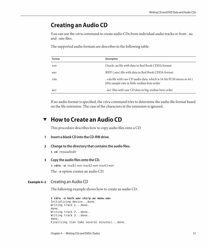
Creating an Audio CDYou can use the cdrw command to create audio CDs from individual audio tracks or from .au
and .wav files.
The supported audio formats are describes in the following table:
Format Description
sun Oracle .au file with data in Red Book CDDA format
wav RIFF (.wav) file with data in Red Book CDDA format
cda .cda file with raw CD audio data, which is 16-bit PCM stereo at 44.1kHz sample rate in little-endian byte order
aur .aur files with raw CD data in big-endian byte order
If no audio format is specified, the cdrw command tries to determine the audio file format basedon the file extension. The case of the characters in the extension is ignored.
▼ How to Create an Audio CDThis procedure describes how to copy audio files onto a CD.
Insert a blank CD into the CD-RW drive.
Change to the directory that contains the audio files.$ cd /myaudiodir
Copy the audio files onto the CD.$ cdrw -a track1.wav track2.wav track3.wav
The -a option creates an audio CD.
Creating an Audio CD
The following example shows how to create an audio CD.
$ cdrw -a bark.wav chirp.au meow.wav
Initializing device...done.
Writing track 1...done.
done.
Writing track 2...done.
Writing track 3...done.
done.
Finalizing (Can take several minutes)...done.
1
2
3
Example 4–2
Writing CD and DVD Data and Audio CDs
Chapter 4 • Writing CDs and DVDs (Tasks) 51

The following example shows how to create a multisession audio CD. The CD is ejected afterthe first session is written. You would need to re-insert the CD before the next writing session.
$ cdrw -aO groucho.wav chico.au harpo.wav
Initializing device...done.
Writing track 1...done.
done.
Writing track 2...done.
Writing track 3...done.
done.
Finalizing (Can take several minutes)...done.
<Re-insert CD>
$ cdrw -a zeppo.au
Initializing device...done.
Writing track 1...done.
done.
Finalizing (Can take several minutes)...done.
▼ How to Extract an Audio Track on a CDUse the following procedure to extract an audio track from a CD and copy the audio track to anew CD.
If you don't use the cdrw -T option to specify the audio file type, the cdrw command uses thefilename extension to determine the audio file type. For example, the cdrw command detectsthat this file is a .wav file.
$ cdrw -x 1 testme.wav
Insert an audio CD into the CD-RW drive.
Extract an audio track.$ cdrw -x -T audio-type 1 audio-file
-x Extracts audio data from an audio CD.
T audio-type Identifies the type of audio file to be extracted. Supported audio types are sun,wav, cda, or aur.
audio-file Identifies the audio track to be extracted.
Copy the track to a new CD.$ cdrw -a audio-file
Extracting and Creating Audio CDs
The following example shows how to extract the first track from an audio CD and name the filesong1.wav.
1
2
3
Example 4–3
Writing CD and DVD Data and Audio CDs
Oracle Solaris Administration: Devices and File Systems • February 201252

$ cdrw -x -T wav 1 song1.wav
Extracting audio from track 1...done.
This example shows how to copy a track to an audio CD.
$ cdrw -a song1.wav
Initializing device...done.
Writing track 1...done.
Finalizing (Can take several minutes)...done.
▼ How to Copy a CDThis procedure describes how to extract all the tracks from an audio CD into a directory andthen copy all of them onto a blank CD.
Note – By default, the cdrw command copies the CD into the /tmp directory. The copying mightrequire up to 700 MB of free space. If there is insufficient space in the /tmp directory for copyingthe CD, use the -m option to specify an alternate directory.
Insert an audio CD into a CD-RW drive.
Create a directory for the audio files.$ mkdir /music_dir
Extract the tracks from the audio CD.$ cdrw -c -m music_dir
An Extracting audio ... message is display for each track.
The CD is ejected when all the tracks are extracted.
Insert a blank CD and press Return.After the tracks are extracted, the audio CD is ejected. You are prompted to insert a blank CD.
Copying a CD
This example shows how to copy one CD to another CD. You must have two CD-RW devices todo this task.
$ cdrw -c -s cdrom0 -d cdrom1
1
2
3
4
Example 4–4
Writing CD and DVD Data and Audio CDs
Chapter 4 • Writing CDs and DVDs (Tasks) 53

▼ How to Erase CD-RW MediaYou have to erase existing CD-RW data before the CD can be rewritten.
Erase the entire media or just the last session on the CD by selecting one of the following:
■ Erase the last session only.
$ cdrw -d cdrom0 -b session
Erasing just the last session with the -b session option is faster than erasing the entiremedia with the -b all option. You can use the -b session option even if you used the cdrwcommand to create a data or audio CD in just one session.
■ Erase the entire media.
$ cdrw -d cdrom0 -b all
●
Writing CD and DVD Data and Audio CDs
Oracle Solaris Administration: Devices and File Systems • February 201254

Managing Devices (Overview/Tasks)
This chapter provides overview information and step-by-step instructions for managingperipheral devices, such as disks, DVD drives, and tape devices, in the Oracle Solaris release.
This is a list of the overview information in this chapter.
■ “What's New in Device Management?” on page 56■ “Where to Find Additional Device Management Tasks” on page 59■ “About Device Drivers” on page 60■ “Automatic Configuration of Devices” on page 61■ “Displaying Device Configuration Information” on page 63■ “Resolving Faulty Devices” on page 67■ “Accessing Devices” on page 71
This is a list of the step-by-step instructions in this chapter.
■ “How to Customize a Driver Configuration” on page 61■ “How to Display System Configuration Information” on page 64■ “How to Resolve a Faulty Device” on page 68■ “How to Add a Device Driver” on page 70■ “How to Add a Peripheral Device” on page 69
Device management in the Oracle Solaris release usually involves adding and removingperipheral devices from systems, possibly adding a third-party device driver to support a device,and displaying system configuration information.
5C H A P T E R 5
55

What's New in Device Management?This section provides information about new device management features in the Oracle Solarisrelease.
■ “Customizing Driver Configuration” on page 56■ “Solaris PCI Resource Manager” on page 56■ “New InfiniBand Administration Features” on page 57■ “New InfiniBand Diagnostic Tools and Commands” on page 57■ “New Ethernet Over InfiniBand Devices” on page 57■ “New Hot Plugging Features” on page 57■ “Device Naming Enhancements” on page 58■ “Support for PCI Express (PCIe)” on page 58
Customizing Driver ConfigurationOracle Solaris 11: In this Solaris release, you can provide a supplemental driver configurationfile, driver.conf, in the /etc/driver/drv directory. In previous Solaris release, you had tomodify the vendor's driver.conf files directly.
In this release, the system automatically merges the driver vendor's /kernel or /platformdriver.conf files with the customized /etc/driver/drv driver.conf files so that the driver seesboth sets of property values.
You can use the prtconf -u command to display the original vendor and customized propertyvalues. Separating vendor driver.conf files and locally customized driver.conf files allows thesystem to be upgraded with new vendor driver.conf files without overwriting youradministrative customizations.
If you have existing modifications in a driver configuration file in the /kernel/drv directoryfrom a previous Solaris release or system, you should copy them over to the /etc/driver/drvdirectory.
For information about creating an /etc/driver/drv/driver.conf file, see “How to Customizea Driver Configuration” on page 61, driver.conf(4), and driver(4).
Solaris PCI Resource ManagerOracle Solaris 11: In this release, a PCI resource manager (PCIRM) is provided to rebalancePCI resources to ensure that when a systems boot, enough resources are assigned to supportPCI Express (PCIe) devices. For example, Single Root I/O Virtualization (SR-IOV) devicesrequire more PCI memory resources for their virtual functions. Most of the firmware today wasdesigned prior to SR-IOV standards, and so, does not recognize the requirement to reserveresources for virtual devices. The resource rebalance process happens automatically at boottime and requires no administration.
What's New in Device Management?
Oracle Solaris Administration: Devices and File Systems • February 201256

New InfiniBand Administration FeaturesOracle Solaris 11: Administration of IPoIB has changed from the earlier releases. In this release,you can create, delete, and view IPoIB datalinks information by using dladm sub-commandscreate-part, delete-part, view-part, and show-ib. These new dladm sub-commandsprovide an easier way to manage IPoIB datalinks and also helps to view and troubleshoot someIB issues. For example, the show-ib sub-commands show how many HCAs are present in thesystem and the corresponding HCA GUIDs. In the new administration model, there are twotypes of IP over IB datalinks.
■ Physical data link - similar to a regular network interface card (NIC) data link■ IB partition data link - similar to a virtual NIC (VNIC)
On a newly installed system, physical links are created automatically by default. Then, you canuse the dladm command to create an IB partition link over the IB physical link. Unlike a NICdata link, an IB physical link cannot be configured, such as plumbed or assigned a IP address forusing the link.
For more information on using the dladm subcommands for managing IB components, see“Administering IPoIB Devices (dladm)” on page 173.
New InfiniBand Diagnostic Tools and CommandsOracle Solaris 11: The system/io/infiniband/open-fabrics package provides a subset of thecommands and utilities from the Open Fabrics Alliance (OFA) Open Fabrics EnterpriseDistribution (OFED) version 1.5.3. The collection of tools provide the ability to list and queryIB devices, diagnose and troubleshoot an IB Fabric, and measure IB performance with acollection of IB user verb micro-benchmarks. For more information, see “Monitoring andTroubleshooting IB Devices” on page 175.
New Ethernet Over InfiniBand DevicesOracle Solaris 11:The Ethernet over InfiniBand (eoib) driver is a multi-threaded, loadable,cloneable, GLD-based STREAMS driver supporting the Data Link Provider Interface, (DLPI)and overall IB ports on a system that are connected to a Oracle Network QDR InfiniBandGateway switch.
New Hot Plugging FeaturesOracle Solaris 11: In this release, the hotplug command is available to manage hot pluggableconnections on PCI Express (PCIe) and PCI SHPC (Standard Hot Plug Controller) devices.This feature is not supported on other bus types, such as USB and SCSI.
What's New in Device Management?
Chapter 5 • Managing Devices (Overview/Tasks) 57

You would still use the cfgadm to manage hot pluggable USB and SCSI devices as in previousSolaris releases. The benefit of using the hotplug features in this release is that in addition toenable and disable operations, the hotplug command provides offline and online capabilitiesfor your supported PCI devices.
For more information, see “PCIe Hot-Plugging With the (hotplug) Command” on page 81.
Device Naming EnhancementsOracle Solaris 11: The /dev name space supports multiple file system instances as needed. Aglobal instance of the /dev file system is created automatically when the system is booted.Subsequent /dev instances are created and mounted when needed, such as when devices areadded to a non-global zone. When a non-global zone is shutdown, the available /dev instance isunmounted and unavailable.
In addition, device configuration is improved in the following ways:
■ Reconfiguration boot is eliminated – In previous Solaris releases, a reconfiguration bootwas needed if you connected a device to a system that is powered off.In this release, performing a reconfiguration boot is unnecessary when attaching devices to asystem that is powered off. Newly attached devices are automatically recognized and theappropriate device links are created when the system is rebooted.For more information, see dev(7FS).
■ Zone device support is simplified – As described above, device support for Oracle Solariszones is enhanced by providing specific instances of the /dev directory for non-globalzones. In addition, zones are no longer dependent upon the devfsadm daemon forreconfiguration of devices within a zone.
■ Pseudo device creation is improved – In this release, the content of the /dev/pts directoryis created on demand in the global /dev name space as well as a/dev instance when neededin a non-global zone. In addition, the ptys links are only visible in the global zone or thenon-global zone from which they are allocated.For more information, see grantpt(3C).
For more information about device configuration, see “Managing Devices in the Oracle SolarisOS” on page 60.
Support for PCI Express (PCIe)Oracle Solaris 11: This Oracle Solaris release provides support for the PCI Express (PCIe)interconnect, which is designed to connect peripheral devices to desktop, enterprise, mobile,communication, and embedded applications, on both SPARC and x86 systems.
What's New in Device Management?
Oracle Solaris Administration: Devices and File Systems • February 201258

The PCIe interconnect is an industry-standard, high-performance, serial I/O bus. For details onPCIe technology, go to the following site:
http://www.pcisig.com/home
The PCIe software provides the following features in this Oracle Solaris release:
■ Support for extended PCIe configuration space■ Support for PCIe baseline error handling and MSI interrupts■ Modified IEEE-1275 properties for PCIe devices■ PCIe hotplug support (both native and ACPI-based) by enhancing the cfgadm_pci
component of the cfgadm command■ ATTN Button usage based PCIe peripheral autoconfiguration
The administrative model for hotplugging PCIe peripherals is the same as for PCI peripherals,which uses the cfgadm command.
Check your hardware platform guide to ensure that PCIe and PCIe hotplug support is providedon your system. In addition, carefully review the instructions for physically inserting orremoving adapters on your system and the semantics of device auto-configuration, ifapplicable.
For information about using the cfgadm command with PCIe peripherals, see “PCI or PCIeHot-Plugging With the cfgadm Command (Task Map)” on page 93.
Where to Find Additional Device Management TasksThe following table describes where to find step-by-step instructions for hot-plugging devicesand adding serial devices, such as printers and modems.
TABLE 5–1 Where to Find Instructions for Adding a Device
Device Management Task For More Information
Add a disk that is not hot-pluggable. Chapter 12, “SPARC: Setting Up Disks (Tasks),” or Chapter 13,“x86: Setting Up Disks (Tasks)”
Hot-plug a SCSI or PCI device. “SCSI Hot-Plugging With the cfgadm Command” on page 84 or“PCI or PCIe Hot-Plugging With the cfgadm Command” onpage 94
Hot-plug a USB device. “Using USB Mass Storage Devices (Task Map)” on page 128
Add a modem. Chapter 16, “Managing the System Console, Terminal Devices,and Power Services (Tasks),” in Oracle Solaris Administration:Common Tasks
Where to Find Additional Device Management Tasks
Chapter 5 • Managing Devices (Overview/Tasks) 59

TABLE 5–1 Where to Find Instructions for Adding a Device (Continued)Device Management Task For More Information
Add a printer. Chapter 15, “Setting Up and Administering Printers by UsingCUPS (Tasks),” in Oracle Solaris Administration: Common Tasks
Secure a device. Chapter 5, “Controlling Access to Devices,” in Oracle SolarisAdministration: Security Services
Managing Devices in the Oracle Solaris OSThe following sections provide overview information about features that manage devices in theOracle Solaris OS. For information about accessing devices, see “Accessing Devices” onpage 71.
Identifying Device SupportYou can use the device detection tool to identify whether your x86 hardware is supported in thisOracle Solaris release. For more information, go to the following site:
http://www.oracle.com/webfolder/technetwork/hcl/hcts/device_detect.jsp
About Device DriversA computer typically uses a wide range of peripheral devices and mass-storage devices. Yoursystem, for example, probably has a disk drive, a keyboard and a mouse, and some kind ofmagnetic backup medium. Other commonly used devices include the following:
■ DVD drives■ Printers and plotters■ Light pens■ Touch-sensitive screens■ Digitizers■ Tablet-and-stylus pairs
The Oracle Solaris software does not directly communicate with all these devices. Each type ofdevice requires different data formats, protocols, and transmission rates.
A device driver is a low-level program that allows the operating system to communicate with aspecific piece of hardware. The driver serves as the operating system's “interpreter” for thatpiece of hardware.
Managing Devices in the Oracle Solaris OS
Oracle Solaris Administration: Devices and File Systems • February 201260

▼ How to Customize a Driver ConfigurationIn the Oracle Solaris 11 release, driver customizations are made in the /etc/driver/drvdirectory rather than in the /kernel directory as in previous releases. This improvement meansthat your driver customizations are not overwritten when the system is upgraded. The files inthe /etc/driver/drv directory are preserved during the upgrade.
Customizing a driver configuration usually means that a per-device parameter or globalproperty that impacts all devices is added or modified.
Become an administrator.
Copy the original vendor supplied driver.conf file to the /etc/driver/drv directory. Forexample:# cp /kernel/drv/sd.conf /etc/driver/drv/sd.conf
Modify the parameter entry and save the file.
For example, the sd.conf includes the following entry for sd device at target 0, lun 0:name="sd" class="scsi" target=0 lun=0;
To add the retries parameter for this device, modify the existing entry as follows:
name="sd" class="scsi" target=0 lun=0 retries=4;
Display the customized property value. For example:# prtconf -u
sd, instance #1
Admin properties:
name=’retries’ type=int items=1
value=00000004
Automatic Configuration of DevicesThe kernel consists of a small generic core with a platform-specific component and a set ofmodules. The kernel is configured automatically in the Oracle Solaris release.
A kernel module is a hardware or software component that is used to perform a specific task onthe system. An example of a loadable kernel module is a device driver that is loaded when thedevice is accessed.
The platform-independent kernel is /kernel/genunix. The platform-specific component is/platform/‘uname -m‘/kernel/unix.
The kernel modules are described in the following table.
1
2
3
4
Managing Devices in the Oracle Solaris OS
Chapter 5 • Managing Devices (Overview/Tasks) 61

TABLE 5–2 Description of Solaris Kernel Modules
Location Directory Contents
/platform/‘uname -m‘/kernel Platform-specific kernel components
/kernel Kernel components common to all platforms that areneeded for booting the system
/usr/kernel Kernel components common to all platforms within aparticular instruction set
The system determines what devices are attached to it at boot time. Then, the kernel configuresitself dynamically, loading needed modules into memory. At this time, device drivers are loadedwhen devices, such as disk devices and tape devices, are accessed. This process is calledautoconfiguration because all kernel modules are loaded automatically when they are needed.
You can customize the way in which kernel modules are loaded by modifying the /etc/systemfile. For instructions on modifying this file, see system(4).
Features and Benefits of AutoconfigurationThe benefits of autoconfiguration are as follows:
■ Main memory is used more efficiently because modules are loaded when needed.■ There is no need to reconfigure the kernel when new devices are added to the system.■ Drivers can be loaded and tested without having to rebuild the kernel and reboot the system.
Autoconfiguration is used when you add a new device (and driver) to the system. In previousreleases, it was necessary to perform a reconfiguration boot if you added a device to a systemthat is shutdown. Device configuration enhancements make a reconfiguration bootunnecessary when a device is added to a system that is shutdown.
You can add, remove, or replace devices in the Oracle Solaris OS while the system is stillrunning, if the system components support hot-plugging. For information about hot-pluggingdevices, see Chapter 6, “Dynamically Configuring Devices (Tasks).”
What You Need for Unsupported DevicesDevice drivers needed to support a wide range of standard devices are included in the OracleSolaris release. These drivers can be found in the /kernel/drv and /platform/‘uname-m‘/kernel/drv directories.
However, if you have purchased an unsupported device, the manufacturer should provide thesoftware that is needed for the device to be properly installed, maintained, and administered.
Managing Devices in the Oracle Solaris OS
Oracle Solaris Administration: Devices and File Systems • February 201262

At a minimum, this software includes a device driver and its associated configuration (.conf)file. The .conf files reside in the drv directories. This software might also include custommaintenance and administrative utilities because the device might be incompatible with OracleSolaris utilities.
For more information about what you need for unsupported devices, contact your devicemanufacturer.
Displaying Device Configuration InformationThree commands are used to display system and device configuration information.
Command Description Man Page
prtconf Displays system configuration information, including the totalamount of memory and the device configuration as described by thesystem's device hierarchy. The output displayed by this commanddepends upon the type of system.
prtconf(1M)
sysdef Displays device configuration information, including systemhardware, pseudo devices, loadable modules, and selected kernelparameters.
sysdef(1M)
dmesg Displays system diagnostic messages as well as a list of devicesattached to the system since the last reboot.
dmesg(1M)
For information on the device names that are used to identify devices on the system, see “DeviceNaming Conventions” on page 72.
driver not attached MessageThe following driver-related message might be displayed by the prtconf and sysdef
commands:
device, instance #number (driver not attached)
This message does not always mean that a driver is unavailable for this device. This messagemeans that no driver is currently attached to the device instance because no device exists at thisnode or the device is not in use. Drivers are loaded automatically when the device is accessed.They are unloaded when the device is not in use.
In-Use Device Error CheckingThe following utilities detect when a specified device is in use:
■ dumpadm
■ format
Managing Devices in the Oracle Solaris OS
Chapter 5 • Managing Devices (Overview/Tasks) 63

■ mkfs and newfs
■ swap
These enhancements mean that the above utilities might detect some of the following usagescenarios:
■ Device is part of a ZFS storage pool■ Device is a dump or swap device■ Mounted file system or an entry for the device exists in the /etc/vfstab file
For example, if you attempt to use the format utility to access an active device, you will see amessage similar to the following:
# format
Searching for disks...done
AVAILABLE DISK SELECTIONS:
0. c1t0d0 <FUJITSU-MAY2073RCSUN72G-0401 cyl 8921 alt 2 hd 255 sec 63>
/pci@0,0/pci1022,7450@2/pci1000,3060@3/sd@0,0
/dev/chassis/SYS/HD0/disk
1. c1t1d0 <FUJITSU-MAY2073RCSUN72G-0401-68.37GB>
/pci@0,0/pci1022,7450@2/pci1000,3060@3/sd@1,0
/dev/chassis/SYS/HD1/disk
Specify disk (enter its number): 0
selecting c1t0d0
[disk formatted]
/dev/dsk/c1t0d0s0 is part of active ZFS pool rpool. Please see zpool(1M).
FORMAT MENU:
.
.
.
▼ How to Display System Configuration InformationUse the output of the prtconf and sysdef commands to identify which disk, tape, and DVDdevices are connected to the system. The output of these commands displays the driver notattached messages next to the device instances. Because these devices are always beingmonitored by some system process, the driver not attached message is usually a goodindication that no device exists at that device instance.
Use the sysdef command to display system configuration information that include pseudodevices, loadable modules, and selected kernel parameters.
Display system and device configuration information.
■ Display all the devices connected to a system.For example, the following prtconf -v output on a SPARC system identifies the diskdevices connected to the system. The detailed disk information is described in the DeviceMinor Nodes section.
●
Managing Devices in the Oracle Solaris OS
Oracle Solaris Administration: Devices and File Systems • February 201264

$ /usr/sbin/prtconf -v | more
Memory size: 32640 Megabytes
System Peripherals (Software Nodes):
SUNW,SPARC-Enterprise-T5220
.
.
.
location: /dev/chassis/SUN-Storage-J4400.0918QAKA24/SCSI_Device__2/disk
Device Minor Nodes:
dev=(27,40)
dev_path=/pci@0/pci@0/pci@8/pci@0/pci@a/LSILogic,sas@0/sd@2,0:a
spectype=blk type=minor
dev_link=/dev/dsk/c4t2d0s0
dev_path=/pci@0/pci@0/pci@8/pci@0/pci@a/LSILogic,sas@0/sd@2,0:a,raw
spectype=chr type=minor
dev_link=/dev/rdsk/c4t2d0s0
Device Minor Layered Under:
mod=zfs accesstype=blk
dev_path=/pseudo/zfs@0
Minor properties:
name=’Nblocks’ type=int64 items=1 dev=(27,40)
value=0000000074702c8f
name=’Size’ type=int64 items=1 dev=(27,40)
value=000000e8e0591e00
.
.
.
■ Display information about one specific device connected to the system.For example, the following prtconf output on a SPARC system displays the sd instancenumber for /dev/dsk/c4t2d0s0.
# prtconf -v /dev/dsk/c4t2d0s0 | grep instance
sd, instance #5
■ Display only the devices that are attached to the system.
# prtconf | grep -v not
■ Display device usage information.For example, the following fuser command displays which processes are accessing the/dev/console device.
# fuser -d /dev/console
/dev/console: 5742o 2269o 20322o 858o
Displaying System Configuration Information
The following prtconf output is displayed on an x86 based system.
# prtconf
System Configuration: Oracle Corporation i86pc
Memory size: 8192 Megabytes
System Peripherals (Software Nodes):
Example 5–1
Managing Devices in the Oracle Solaris OS
Chapter 5 • Managing Devices (Overview/Tasks) 65

i86pc
scsi_vhci, instance #0
pci, instance #0
pci108e,4843, instance #0
pci8086,25e2, instance #0
pci8086,3500, instance #7
pci8086,3510, instance #9
pci8086,3518, instance #10
pci108e,4843, instance #0
pci108e,4843, instance #1
pci8086,350c, instance #8
pci8086,25e3 (driver not attached)
pci8086,25f8, instance #2
pci108e,286, instance #0
disk, instance #0
disk, instance #2
disk, instance #3
disk, instance #1
pci8086,25e5 (driver not attached)
pci8086,25f9 (driver not attached)
pci8086,25e7 (driver not attached)
pci108e,4843, instance #0 (driver not attached)
pci108e,4843, instance #1
pci108e,4843, instance #2 (driver not attached)
pci108e,4843 (driver not attached)
pci108e,4843 (driver not attached)
pci108e,4843 (driver not attached)
pci108e,4843 (driver not attached)
pci8086,2690, instance #6
pci108e,125e, instance #2
pci108e,125e, instance #3
pci108e,4843, instance #0
pci108e,4843, instance #1
device, instance #0
keyboard, instance #0
mouse, instance #1
pci108e,4843, instance #2
pci108e,4843, instance #3
pci108e,4843, instance #0
storage, instance #0
disk, instance #4
.
.
.
The following sysdef output is displayed from an x86 based system.
# sysdef
* Hostid
*
29f10b4d
*
* i86pc Configuration
*
*
* Devices
*
+boot (driver not attached)
Managing Devices in the Oracle Solaris OS
Oracle Solaris Administration: Devices and File Systems • February 201266

memory (driver not attached)
aliases (driver not attached)
chosen (driver not attached)
i86pc-memory (driver not attached)
i86pc-mmu (driver not attached)
openprom (driver not attached)
options, instance #0
packages (driver not attached)
delayed-writes (driver not attached)
itu-props (driver not attached)
isa, instance #0
motherboard (driver not attached)
pnpADP,1542, instance #0
asy, instance #0
asy, instance #1
lp, instance #0 (driver not attached)
fdc, instance #0
fd, instance #0
fd, instance #1 (driver not attached)
kd (driver not attached)
kdmouse (driver not attached)
.
.
.
Resolving Faulty DevicesA device retirement mechanism isolates a device as faulty by the fault management framework(FMA). This feature allows faulty devices to be safely and automatically inactivated to avoiddata loss, data corruption, or panics and system down time. The retirement process is donesafely, taking into account the stability of the system after the device has been retired.
Critical devices are never retired. If you need to manually replace a retired device, use the fmadmrepair command after the device replacement so that system knows that the device is replaced,in addition to the manual replacement steps.
For more information, see fmadm(1M).
A general message regarding device retirement is displayed on the console and written to the/var/adm/messages file so that you aware of a retired device. For example:
Aug 9 18:14 starbug genunix: [ID 751201 kern.notice] NOTICE: One or more I/O devices have been retired
You can use the prtconf command to identify specific retired devices. For example:
# prtconf
.
.
.
pci, instance #2
scsi, instance #0
disk (driver not attached)
Managing Devices in the Oracle Solaris OS
Chapter 5 • Managing Devices (Overview/Tasks) 67

tape (driver not attached)
sd, instance #3
sd, instance #0 (retired)
scsi, instance #1 (retired)
disk (retired)
tape (retired)
pci, instance #3
network, instance #2 (driver not attached)
network, instance #3 (driver not attached)
os-io (driver not attached)
iscsi, instance #0
pseudo, instance #0
.
.
.
▼ How to Resolve a Faulty DeviceUse the steps below to resolve a faulty device or a device that has been retired.
You can also review ZFS device problem or failure information by using the zpool status orthe fmdump command. For ZFS device problem or failure information, see Chapter 11, “OracleSolaris ZFS Troubleshooting and Pool Recovery,” in Oracle Solaris Administration: ZFS FileSystems.
Identify the faulted device with the fmadm faulty command.# fmadm faulty
--------------- ------------------------------------ -------------- ---------
TIME EVENT-ID MSG-ID SEVERITY
--------------- ------------------------------------ -------------- ---------
May 06 03:38:06 0376b4b6-fce7-c0f0-ffd9-a0a685376284 ZFS-8000-D3 Major
Host : neo-2
Platform : Sun-Fire-X4140 Chassis_id : 0904QAD02C
Product_sn :
Fault class : fault.fs.zfs.device
Affects : zfs://pool=tank/vdev=c26c72a8ffcff889
faulted and taken out of service
Problem in : zfs://pool=tank/vdev=c26c72a8ffcff889
faulted and taken out of service
Description : A ZFS device failed. Refer to http://sun.com/msg/ZFS-8000-D3 for
more information.
Response : No automated response will occur.
Impact : Fault tolerance of the pool may be compromised.
Action : Run ’zpool status -x’ and replace the bad device.
Replace the faulty or retired device or clear the device error.After a faulty device is replaced in a ZFS storage pool, clear the device error. For example:# zpool clear rpool c4t0d0s0
1
2
Managing Devices in the Oracle Solaris OS
Oracle Solaris Administration: Devices and File Systems • February 201268

If an intermittent device error occurred but the device was not replaced, you can attempt toclear the error as shown above.
Clear the FMA fault.# fmadm repair 0376b4b6-fce7-c0f0-ffd9-a0a685376284
Confirm that the fault is cleared.# fmadm faulty
Adding a Peripheral Device to a SystemAdding a new peripheral device that is not-pluggable usually involves the following:■ Shutting down the system■ Connecting the device to the system■ Rebooting the system
Use “How to Add a Peripheral Device” on page 69 to add the following devices that are nothot-pluggable to a system:■ DVD drive■ Secondary disk drive■ Tape drive■ SBUS card
In some cases, you might have to add a third-party device driver to support the new device.
For information on hot-plugging devices, see Chapter 6, “Dynamically Configuring Devices(Tasks).”
▼ How to Add a Peripheral DeviceBecome an administrator.For more information, see “How to Use Your Assigned Administrative Rights” in Oracle SolarisAdministration: Security Services.
(Optional) If you need to add a device driver to support the device, complete the procedure“How to Add a Device Driver”on page 70.
Shut down the system.# shutdown -i0 -g30 -y
-i0 Brings the system to the 0 init state, which is the appropriate state for turning thesystem power off for adding and removing devices.
3
4
1
2
3
Adding a Peripheral Device to a System
Chapter 5 • Managing Devices (Overview/Tasks) 69

-g30 Shuts the system down in 30 seconds. The default is 60 seconds.
-y Continues the system shutdown without user intervention. Otherwise, you areprompted to continue the shutdown process.
Select one of the following to turn off power to the system after it is shut down:
■ For SPARC platforms, it is safe to turn off power if the ok prompt is displayed.■ For x86 platforms, it is safe to turn off power if the type any key to continue prompt is
displayed.
Turn off power to all peripheral devices.For the location of power switches on any peripheral devices, refer to the hardware installationguides that accompany your peripheral devices.
Install the peripheral device, making sure that the device you are adding has a different targetnumber than the other devices on the system.Often, a small switch is located at the back of the disk for selecting the target number.
Refer to the hardware installation guide that accompanies the peripheral device for informationon installing and connecting the device.
Turn on the power to the system.The system boots to multiuser mode, and the login prompt is displayed.
Verify that the peripheral device has been added by attempting to access the device.For information on accessing the device, see “Accessing Devices” on page 71.
▼ How to Add a Device DriverIn the Oracle Solaris 11 release, the pkg commands are used to add packages to the system.Device driver packages might still be in SRV4 package format so the steps below use the pkgaddcommand instead of the pkg install command.
This procedure assumes that the device has already been added to the system. If not, see “WhatYou Need for Unsupported Devices” on page 62.
Become an administrator.For more information, see “How to Use Your Assigned Administrative Rights” in Oracle SolarisAdministration: Security Services.
Place the media into the drive.
4
5
6
7
8
1
2
Adding a Peripheral Device to a System
Oracle Solaris Administration: Devices and File Systems • February 201270

Install the driver.# pkgadd [-d] device package-name
Verify that the package has been added correctly.# pkgchk package-name#
The system prompt returns with no response if the package is installed correctly.
Adding a Device Driver
The following example shows how to install and verify a package called XYZdrv.
# pkgadd XYZdrv
(licensing messages displayed).
.
.
Installing XYZ Company driver as <XYZdrv>
.
.
.
Installation of <XYZdrv> was successful.
# pkgchk XYZdrv
#
Accessing DevicesYou need to know how to specify device names when using commands to manage disks, filesystems, and other devices. In most cases, you can use logical device names to represent devicesthat are connected to the system. Both logical and physical device names are represented on thesystem by logical and physical device files.
How Device Information Is CreatedWhen a system is booted for the first time, a device hierarchy is created to represent all thedevices connected to the system. The kernel uses the device hierarchy information to associatedrivers with their appropriate devices. The kernel also provides a set of pointers to the driversthat perform specific operations.
3
4
Example 5–2
Accessing Devices
Chapter 5 • Managing Devices (Overview/Tasks) 71

How Devices Are ManagedThe devfs file system manages the /devices directory, which is the name space of all devices onthe system. This directory represents the physical devices that consists of actual bus and deviceaddresses.
The dev file system manages the /dev directory, which is the name space of logical devicenames.
By default, the devfsadm command attempts to load every driver in the system and attach to allpossible device instances. Then, devfsadm creates the device files in the /devices directory andthe logical links in the /dev directory. The devfsadm command also maintains thepath_to_inst instance database.
Updates to the /dev and /devices directories in response to dynamic reconfiguration events orfile system accesses are handled by devfsadmd, the daemon version of the devfsadm command.This daemon is started by the service management facility when a system is booted.
Because the devfsadmd daemon automatically detects device configuration changes generatedby any reconfiguration event, there is no need to run this command interactively.
For more information, see the following references:
■ devfsadm(1M)■ dev(7FS)■ devfs(7FS)■ path_to_inst(4)
Device Naming ConventionsDevices are referenced in three ways in the Oracle Solaris OS.
■ Physical device name – Represents the full device path name in the device informationhierarchy. The physical device name is created by when the device is first added to thesystem. Physical device files are found in the /devices directory.
■ Instance name – Represents the kernel's abbreviation name for every possible device on thesystem. For example, sd0 and sd1 represent the instance names of two disk devices. Instancenames are mapped in the /etc/path_to_inst file.
■ Logical device name – The logical device name is created by when the device is first addedto the system. Logical device names are used with most file system commands to refer todevices. For a list of file commands that use logical device names, see Table 5–3. Logicaldevice files in the /dev directory are symbolically linked to physical device files in the/devices directory.
Accessing Devices
Oracle Solaris Administration: Devices and File Systems • February 201272

The preceding device name information is displayed with the following commands:
■ dmesg
■ format
■ sysdef
■ prtconf
Logical Disk Device NamesLogical device names are used to access disk devices when you perform the following tasks:
■ Add a new disk to the system.■ Move a disk from one system to another system.■ Access or mount a file system residing on a local disk.■ Back up a local file system.
Many administration commands take arguments that refer to a disk slice or file system.
Refer to a disk device by specifying the subdirectory to which it is symbolically linked, either/dev/dsk or /dev/rdsk, followed by a string identifying the particular controller, disk, andslice.
Specifying the Disk SubdirectorySome disk and file administration commands require the use of either a raw (or character)device interface, or a block device interface. The distinction is made by how data is read from thedevice.
Raw device interfaces transfer only small amounts of data at a time. Block device interfacesinclude a buffer from which large blocks of data are read at once.
FIGURE 5–1 Description of Logical Device Names
/dev/[r]dsk/cvtwdx[sy,pz]
Logical controller number
Physical bus target number
Drive number
Raw disk device subdirectory
Devices directory
Slice number (s0 to s7) or fdisk partition number (p0 to p4)
Accessing Devices
Chapter 5 • Managing Devices (Overview/Tasks) 73

Different commands require different interfaces:
■ When a command requires the raw device interface, specify the /dev/rdsk subdirectory.(The “r” in rdsk stands for “raw.”)
■ When a command requires the block device interface, specify the /dev/dsk subdirectory.■ When you are not sure whether a command requires use of /dev/dsk or /dev/rdsk, check
the man page for that command.
The following table shows which interface is required for some commonly used disk and filesystem commands.
TABLE 5–3 Device Interface Type Required by Some Frequently Used Commands
Command Reference Interface Type Example of Use
dumpadm(1M) Block dumpadm -d /dev/zvol/dsk/rpool/dump
prtvtoc(1M) Raw prtvtoc /dev/rdsk/c0t0d0s0
swap(1M) Block swap -a /dev/zvol/dsk/rpool/swap
Direct and Bus-Oriented ControllersYou might access disk partitions or slices differently depending upon whether the disk device isconnected to a direct or bus-oriented controller. Generally, direct controllers do not include atarget identifier in the logical device name.
The conventions for both types of controllers are explained in the following subsections.
Note – Controller numbers are assigned automatically during system initialization. Thenumbers are strictly logical and imply no direct mapping to physical controllers.
x86: Disks With Direct ControllersTo specify a slice on a disk with an IDE controller on an x86 based system, follow the namingconvention shown in the following figure.
FIGURE 5–2 x86: Disks With Direct Controllers
cwdx [sy, pz]
Slice number (s0 to s7) or fdisk partition number (p0 to p4)
Drive number
Logical controller number
Accessing Devices
Oracle Solaris Administration: Devices and File Systems • February 201274

To indicate the entire Solaris fdisk partition, specify slice 2 (s2).
If you have only one controller on your system, w is usually 0.
Disks With Bus-Oriented ControllersTo specify a slice on a disk with a bus-oriented controller, SCSI for instance, follow the namingconvention shown in the following figure.
On a SPARC based system with directly connected disks such as the IDE disks on anUltraSPARC system, the naming convention is the same as that for systems with bus-orientedcontrollers.
If you have only one controller on your system, w is usually 0.
For SCSI controllers, x is the target address set by the switch on the back of the unit, and y is thelogical unit number (LUN) of the drive attached to the target. If the disk has an embeddedcontroller, y is usually 0.
To indicate the whole disk, specify slice 2 (s2).
Logical Tape Device NamesLogical tape device files are found in the /dev/rmt/* directory as symbolic links from the/devices directory.
FIGURE 5–3 Disks With Bus-Oriented Controllers
cvtwdx[sy,pz]
Slice number (s0 to s7) or fdisk partition number (p0 to p4)
Drive number
Physical bus target number
Logical controller number
Accessing Devices
Chapter 5 • Managing Devices (Overview/Tasks) 75

The first tape device connected to the system is 0 (/dev/rmt/0). Tape density values (l, m, h, c,and u) are described in Chapter 21, “Managing Tape Drives (Tasks).”
Logical Removable Media Device NamesSince removable media is managed by removable media management services, the logicaldevice name is usually not used unless you want to mount the media manually.
The logical device name that represents the removable media devices on a system are describedin Chapter 3, “Accessing Removable Media (Tasks).”
FIGURE 5–4 Logical Tape Device Names
/dev/rmt/xy
Drive number (0-n)
Raw magnetic tape device directory
Devices directory
Optional density l low m medium h high u ultra c compressed
Accessing Devices
Oracle Solaris Administration: Devices and File Systems • February 201276

Dynamically Configuring Devices (Tasks)
This chapter provides instructions for dynamically configuring devices in the Oracle Solaris OS.You can add, remove, or replace devices in the Oracle Solaris OS while the system is stillrunning, if the system components support hot-plugging. If the system components do notsupport hot-plugging, you can reboot the system to reconfigure the devices.
For information on the procedures associated with dynamically configuring devices, see thefollowing:
■ “SCSI Hot-Plugging With the cfgadm Command (Task Map)” on page 83■ “PCI or PCIe Hot-Plugging With the cfgadm Command (Task Map)” on page 93■ “SATA Hot-Plugging With the cfgadm Command” on page 100■ “Application Developer RCM Script (Task Map)” on page 103■ “System Administrator RCM Script (Task Map)” on page 104
For information on hot-plugging USB devices with the cfgadm command, see “Hot-PluggingUSB Devices With the cfgadm Command” on page 151.
For information on hot-plugging InfiniBand devices with cfgadm command, see Chapter 9,“Using InfiniBand Devices (Overview/Tasks).”
For information about accessing devices, see “Accessing Devices” on page 71.
Dynamic Reconfiguration and Hot-PluggingHot-plugging is the ability to physically add, remove, or replace system components while thesystem is running. Dynamic reconfiguration refers to the ability to hot-plug systemcomponents. This term also refers to the general ability to move system resources (bothhardware and software) around in the system or to disable them in some way without physicallyremoving them from the system.
Generally, you can hot-plug the following bus types:
6C H A P T E R 6
77

■ USB■ Fibre Channel■ 1394■ ATA■ SCSI■ Infiniband
In addition, you can hot-plug the following devices with the cfgadm command:
■ USB devices on SPARC and x86 platforms■ SCSI or SAS devices on SPARC and x86 platforms■ PCI devices on SPARC and x86 platforms■ PCIe devices on SPARC or x86 platforms■ SATA devices on SPARC and x86 platforms■ InfiniBand devices on SPARC and x86 platforms
Features of the cfgadm command include the following:
■ Displaying system component status■ Testing system components■ Changing component configurations■ Displaying configuration help messages
The benefit of using the cfgadm command to reconfigure systems components is that you canadd, remove, or replace components while the system is running. An added benefit is that thecfgadm command guides you through the steps needed to add, remove, or replace systemcomponents.
For step-by-step instructions on hot-plugging components, see the following:
■ “SCSI Hot-Plugging With the cfgadm Command” on page 84■ “PCI or PCIe Hot-Plugging With the cfgadm Command” on page 94■ “SATA Hot-Plugging With the cfgadm Command” on page 100■ cfgadm(1M)
Note – Not all SCSI and PCI controllers support hot-plugging with the cfgadm command.
As part of Oracle's high availability strategy, dynamic reconfiguration is expected to be used inconjunction with additional layered products, such as alternate pathing or fail over software.Both products provide fault tolerance in the event of a device failure.
Without any high availability software, you can replace a failed device by manually stopping theappropriate applications, unmounting noncritical file systems, and then proceeding with theadd or remove operations.
Dynamic Reconfiguration and Hot-Plugging
Oracle Solaris Administration: Devices and File Systems • February 201278

Note – Some systems have slots that hot-pluggable and slots that are not hot-pluggable. Forinformation about hot-plugging devices on your specific hardware configuration, such as onenterprise-level systems, refer to your hardware configuration documentation.
Attachment PointsThe cfgadm command displays information about attachment points, which are locations in thesystem where dynamic reconfiguration operations can occur.
An attachment point consists of the following:
■ An occupant, which represents a hardware component that can be configured into thesystem
■ A receptacle, which is the location that accepts the occupant
Attachment points are represented by logical and physical attachment point IDs (Ap_Ids). Thephysical Ap_Id is the physical path name of the attachment point. The logical Ap_Id is auser-friendly alternative for the physical Ap_Id. For more information on Ap_Ids, refer tocfgadm(1M).
The logical Ap_Id for a SCSI Host Bus Adapter (HBA), or SCSI controller, is usually representedby the controller number, such as c0.
In cases where no controller number has been assigned to a SCSI HBA, then an internallygenerated unique identifier is provided. An example of a unique identifier for a SCSI controlleris the following:
fas1:scsi
The logical Ap_Id for a SCSI device usually has this format:
HBA-logical-apid::device-identifier
In the following example, c0 is the logical Ap_Id for the SCSI HBA:
c0::dsk/c0t3d0
The device identifier is typically derived from the logical device name for the device in the /devdirectory. For example, a tape device with logical device name, /dev/rmt/1, has the followinglogical Ap_Id:
c0::rmt/1
If a logical Ap_Id of a SCSI device cannot be derived from the logical name in the /dev directory,then an internally generated unique identifier is provided. An example of an identifier for the/dev/rmt/1 tape device is the following:
Dynamic Reconfiguration and Hot-Plugging
Chapter 6 • Dynamically Configuring Devices (Tasks) 79

c0::st4
For more information on SCSI Ap_Ids, refer to cfgadm_scsi(1M).
The cfgadm command represents all resources and dynamic reconfiguration operations interms of a common set of states (such as configured and unconfigured) and operations (such asconnect, configure, unconfigure, and so on). For more information on these common states andoperations, see cfgadm(1M).
The following table shows the receptacle and occupant states for the SCSI HBA attachmentpoints.
Receptacle State Description Occupant State Description
empty N/A for SCSI HBA configured One or more devices isconfigured on the bus
disconnected Bus quiesced unconfigured No devices are configured
connected Bus active
The following table shows the receptacle and occupant states for SCSI device attachment points.
Receptacle State Description Occupant State Description
empty N/A for SCSI devices configured Device is configured
disconnected Bus quiesced unconfigured Device is not configured
connected Bus active
The state of SCSI attachment points is unknown unless special hardware indicates otherwise.For instructions on displaying SCSI component information, see “How to Display InformationAbout SCSI Devices” on page 84.
Detaching PCI or PCIe Adapter CardsA PCI adapter card that is hosting nonvital system resources can be removed if the device driversupports hot-plugging. A PCI adapter card is not detachable if it is a vital system resource. For aPCI adapter card to be detachable, the following conditions must be met:
■ The device driver must support hot-plugging.■ Critical resources must be accessible through an alternate pathway.
For example, if a system has only one Ethernet card installed in it, the Ethernet card cannot bedetached without losing the network connection. This detachment requires additional layeredsoftware support to keep the network connection active.
Dynamic Reconfiguration and Hot-Plugging
Oracle Solaris Administration: Devices and File Systems • February 201280

Attaching PCI or PCIe Adapter CardsA PCI adapter card can be added to the system as long as the following conditions are met:
■ There are slots available.■ The device driver supports hot-plugging for this adapter card.
For step-by-step instructions on adding or removing a PCI adapter card, see “PCI or PCIeHot-Plugging With the cfgadm Command” on page 94.
PCIe Hot-Plugging With the (hotplug) CommandYou can use the hotplug command to manage hot pluggable connections, where a connectioncan be a connector or port, on PCI Express (PCIe) and PCI SHPC devices only. A hotplugconnector is a physical representation in the system where a component is inserted or removed.A hotplug port is a logical representation in the system device tree where the connection of adevice to the system is managed.
You can use the hotplug features to online or offline a device, even an on-board device, withoutphysically adding or removing the device from the system.
You must enable the hotplug service to manage devices with the hotplug command.
# svcadm enable svc:/system/hotplug:default
The following examples describe how to use the hotplug command.
Display all the PCI/PCIe hot pluggable connectors/ports (virtual and physical) in the system asfollows:
# hotplug list -lv
Configure an Ethernet card in a PCIe slot. For example:
# hotplug enable /pci0,0 pcie0
Unconfigure an Ethernet card in a PCIe slot. For example:
# hotplug disable /pci0,0 pcie0
Offline a PCI device node, which means detach the device driver for that node. For example:
# hotplug offline /pci0,0/pci1 pci.0,2
Online a PCI device node, which means attach the driver for that node. For example:
# hotplug online /pci0,0/pci1 pci.0,2
Dynamic Reconfiguration and Hot-Plugging
Chapter 6 • Dynamically Configuring Devices (Tasks) 81

Install dependent ports of an IOV physical function. For example:
# hotplug install /pci@400/pci@1/pci@0/pci@4 pci.0,1
Then, display the resulting IOV virtual functions that were probed. For example:
# hotplug list -v /pci@400/pci@1/pci@0/pci@4 pci.0,1
<pci.0,1> (ONLINE)
{ IOV physical function }
{ IOV virtual function ’pci.0,81’ }
{ IOV virtual function ’pci.0,83’ }
{ IOV virtual function ’pci.0,85’ }
{ IOV virtual function ’pci.0,87’ }
<pci.0,81> (OFFLINE)
ethernet@0,81
<pci.0,83> (OFFLINE)
ethernet@0,83
<pci.0,85> (OFFLINE)
ethernet@0,85
<pci.0,87> (OFFLINE)
ethernet@0,87
Uninstall the dependent ports of an IOV physical function. For example:
# hotplug uninstall /pci@400/pci@1/pci@0/pci@4 pci.0,0
This operation fails if a dependent IOV virtual function is busy. For example:
# hotplug uninstall /pci@400/pci@1/pci@0/pci@4 pci.0,0
ERROR: devices or resources are busy.
ethernet@0,81:
{ Network interface igbvf1 }
{ igbvf1: hosts IP addresses: 10.0.0.1 }
{ Plumbed IP Address }
Troubleshooting PCI Hot Plug Operations (hotplug)You might see the following maintenance states for an attached device in a hotplug port.
/pci@0,0/pci10de,5d@e <pci.a,1> (MAINTENANCE)
.
.
./pci@0,0/pci108e,534a@d <pci.0,0> (MAINTENANCE-SUSPENDED)
The above messages indicate that a fault event or a maintenance operation occurred. TheMAINTENANCE states mean that a device is in use, but it is not fully operational. TheMAINTENANCE-SUSPENDED state means that the device is live suspended, due to a maintenanceoperation. For example, reconfiguring the device hardware.
The following service must be running to use the hotplug command.
svc:/system/hotplug:default
Otherwise, you will see the following message:
Dynamic Reconfiguration and Hot-Plugging
Oracle Solaris Administration: Devices and File Systems • February 201282

ERROR: hotplug service is not available.
The following error message is displayed on systems that do not have any supported I/O buses:
ERROR: there are no connections to display.
(See hotplug(1m) for more information.)
The above message could mean that the system might have other hot-pluggable I/O devices, butyou need to use the cfgadm command rather than the hotplug command to manage thesedevices.
SCSI Hot-Plugging With the cfgadm Command (Task Map)
Task Description For Instructions
Display information about SCSIdevices.
Display information about SCSIcontrollers and devices.
“How to Display InformationAbout SCSI Devices” on page 84
Unconfigure a SCSI controller. Unconfigure a SCSI controller. “How to Unconfigure a SCSIController” on page 85
Configure a SCSI controller. Configure a SCSI controller thatwas previously unconfigured.
“How to Configure a SCSIController” on page 85
Configure a SCSI device. Configure a specific SCSI device. “How to Configure a SCSI Device”on page 86
Disconnect a SCSI controller. Disconnect a specific SCSIcontroller.
“How to Disconnect a SCSIController” on page 86
Connect a SCSI controller. Connect a specific SCSI controllerthat was previously disconnected.
“SPARC: How to Connect a SCSIController” on page 87
Add a SCSI device to a SCSI bus. Add a specific SCSI device to aSCSI bus.
“SPARC: How to Add a SCSIDevice to a SCSI Bus” on page 88
Replace an identical device on aSCSI controller.
Replace a device on the SCSI buswith another device of the sametype.
“SPARC: How to Replace anIdentical Device on a SCSIController” on page 89
Remove a SCSI device. Remove a SCSI device from thesystem.
“SPARC: How to Remove a SCSIDevice” on page 90
Troubleshoot SCSI configurationproblems.
Resolve a failed SCSI unconfigureoperation.
“How to Resolve a Failed SCSIUnconfigure Operation” onpage 93
SCSI Hot-Plugging With the cfgadm Command (Task Map)
Chapter 6 • Dynamically Configuring Devices (Tasks) 83

SCSI Hot-Plugging With the cfgadm CommandThis section describes various SCSI hot-plugging procedures that you can perform with thecfgadm command.
Note – The SCSI framework generally supports hot-plugging of SCSI devices. However, youshould consult your hardware documentation to confirm whether hot-plugging is supportedfor your SCSI devices.
These procedures use specific devices as examples to illustrate how to use the cfgadm commandto hot-plug SCSI components. The device information that you supply, and that the cfgadmcommand displays, depends on your system configuration.
All of the procedures in this section require administrative privileges that are not generallygranted to user accounts. For more information, see “How to Use Your AssignedAdministrative Rights” in Oracle Solaris Administration: Security Services.
▼ How to Display Information About SCSI DevicesThe following procedure uses SCSI controllers c0 and c1 and the devices that are attached tothem in the examples of the type of device configuration information that you can display withthe cfgadm command.
Note – If the SCSI device is not supported by the cfgadm command, the device does not displayin the cfgadm command output.
Become an administrator.
Display information about attachment points on the system.# cfgadm -l
Ap_Id Type Receptacle Occupant Condition
c0 scsi-bus connected configured unknown
c1 scsi-bus connected configured unknown
In this example, c0 and c1 represent two SCSI controllers.
Display information about a system's SCSI controllers and their attached devices.# cfgadm -al
Ap_Id Type Receptacle Occupant Condition
c0 scsi-bus connected configured unknown
c0::dsk/c0t0d0 disk connected configured unknown
c0::rmt/0 tape connected configured unknown
c1 scsi-bus connected configured unknown
c1::dsk/c1t3d0 disk connected configured unknown
c1::dsk/c1t4d0 unavailable connected unconfigured unknown
1
2
3
SCSI Hot-Plugging With the cfgadm Command
Oracle Solaris Administration: Devices and File Systems • February 201284

Note – The cfgadm -l commands displays information about SCSI HBAs but not SCSI devices.Use the cfgadm -al command to display information about SCSI devices such as disk andtapes.
▼ How to Unconfigure a SCSI ControllerThe following procedure uses SCSI controller c1 in the example of unconfiguring a SCSIcontroller.
Become an administrator.
Unconfigure a SCSI controller.# cfgadm -c unconfigure c1
Verify that the SCSI controller is unconfigured.# cfgadm -al
Ap_Id Type Receptacle Occupant Condition
c0 scsi-bus connected configured unknown
c0::dsk/c0t0d0 disk connected configured unknown
c0::rmt/0 tape connected configured unknown
c1 scsi-bus connected unconfigured unknown
Notice that the Occupant column for c1 specifies unconfigured, indicating that the SCSI bushas no configured occupants.
If the unconfigure operation fails, see “How to Resolve a Failed SCSI Unconfigure Operation”on page 93.
▼ How to Configure a SCSI ControllerThe following procedure uses SCSI controller c1 in the example of configuring a SCSIcontroller.
Become an administrator.
Configure a SCSI controller.# cfgadm -c configure c1
Verify that the SCSI controller is configured.# cfgadm -al
Ap_Id Type Receptacle Occupant Condition
c0 scsi-bus connected configured unknown
c0::dsk/c0t0d0 disk connected configured unknown
c0::rmt/0 tape connected configured unknown
1
2
3
1
2
3
SCSI Hot-Plugging With the cfgadm Command
Chapter 6 • Dynamically Configuring Devices (Tasks) 85

c1 scsi-bus connected configured unknown
c1::dsk/c1t3d0 disk connected configured unknown
c1::dsk/c1t4d0 unavailable connected unconfigured unknown
The previous unconfigure procedure removed all devices on the SCSI bus. Now all the devicesare configured back into the system.
▼ How to Configure a SCSI DeviceThe following procedure uses SCSI disk c1t4d0 in the example of configuring a SCSI device.
Become an administrator.
Identify the device to be configured.# cfgadm -al
Ap_Id Type Receptacle Occupant Condition
c0 scsi-bus connected configured unknown
c0::dsk/c0t0d0 disk connected configured unknown
c0::rmt/0 tape connected configured unknown
c1 scsi-bus connected configured unknown
c1::dsk/c1t3d0 disk connected configured unknown
c1::dsk/c1t4d0 unavailable connected unconfigured unknown
Configure the SCSI device.# cfgadm -c configure c1::dsk/c1t4d0
Verify that the SCSI device is configured.# cfgadm -al
Ap_Id Type Receptacle Occupant Condition
c0 scsi-bus connected configured unknown
c0::dsk/c0t0d0 disk connected configured unknown
c0::rmt/0 tape connected configured unknown
c1 scsi-bus connected configured unknown
c1::dsk/c1t3d0 disk connected configured unknown
c1::dsk/c1t4d0 disk connected configured unknown
▼ How to Disconnect a SCSI Controller
Caution – Disconnecting a SCSI device must be done with caution, particularly when you aredealing with controllers for disks that contain critical file systems such as root (/), usr, var, andthe swap partition. The dynamic reconfiguration software cannot detect all cases where a systemhang might result. Use this procedure with caution.
The following procedure uses SCSI controller c1 in the example of disconnecting a SCSI device.
Become an administrator.
1
2
3
4
1
SCSI Hot-Plugging With the cfgadm Command
Oracle Solaris Administration: Devices and File Systems • February 201286

Verify that the device is connected before you disconnect it.# cfgadm -al
Ap_Id Type Receptacle Occupant Condition
c0 scsi-bus connected configured unknown
c0::dsk/c0t0d0 disk connected configured unknown
c0::rmt/0 tape connected configured unknown
c1 scsi-bus connected configured unknown
c1::dsk/c1t3d0 disk connected configured unknown
c1::dsk/c1t4d0 disk connected configured unknown
Disconnect the SCSI controller.# cfgadm -c disconnect c1
WARNING: Disconnecting critical partitions may cause system hang.
Continue (yes/no)? y
Caution – This command suspends all I/O activity on the SCSI bus until the cfgadm -c connectcommand is used. The cfgadm command does some basic checking to prevent critical partitionsfrom being disconnected, but it cannot detect all cases. Inappropriate use of this command canresult in a system hang and could require a system reboot.
Verify that the SCSI bus is disconnected.# cfgadm -al
Ap_Id Type Receptacle Occupant Condition
c0 scsi-bus connected configured unknown
c0::dsk/c0t0d0 disk connected configured unknown
c0::rmt/0 tape connected configured unknown
c1 unavailable disconnected configured unknown
c1::dsk/c1t3d0 unavailable disconnected configured unknown
c1::dsk/c1t4d0 unavailable disconnected configured unknown
The controller and all the devices that are attached to it are disconnected from the system.
▼ SPARC: How to Connect a SCSI ControllerThe following procedure uses SCSI controller c1 in the example of connecting a SCSIcontroller.
Become an administrator.
Verify that the device is disconnected before you connect it.# cfgadm -al
Ap_Id Type Receptacle Occupant Condition
c0 scsi-bus connected configured unknown
c0::dsk/c0t0d0 disk connected configured unknown
c0::rmt/0 tape connected configured unknown
c1 unavailable disconnected configured unknown
c1::dsk/c1t3d0 unavailable disconnected configured unknown
c1::dsk/c1t4d0 unavailable disconnected configured unknown
2
3
4
1
2
SCSI Hot-Plugging With the cfgadm Command
Chapter 6 • Dynamically Configuring Devices (Tasks) 87

Connect the SCSI controller.# cfgadm -c connect c1
Verify that the SCSI controller is connected.# cfgadm -al
Ap_Id Type Receptacle Occupant Condition
c0 scsi-bus connected configured unknown
c0::dsk/c0t0d0 disk connected configured unknown
c0::rmt/0 tape connected configured unknown
c1 scsi-bus connected configured unknown
c1::dsk/c1t3d0 disk connected configured unknown
c1::dsk/c1t4d0 disk connected configured unknown
▼ SPARC: How to Add a SCSI Device to a SCSI BusSCSI controller c1 is used in the example of how to add a SCSI device to a SCSI bus.
Note – When you add devices, you specify the Ap_Id of the SCSI HBA (controller) to which thedevice is attached, not the Ap_Id of the device itself.
Become an administrator.
Identify the current SCSI configuration.# cfgadm -al
Ap_Id Type Receptacle Occupant Condition
c0 scsi-bus connected configured unknown
c0::dsk/c0t0d0 disk connected configured unknown
c0::rmt/0 tape connected configured unknown
c1 scsi-bus connected configured unknown
c1::dsk/c1t3d0 disk connected configured unknown
Add the SCSI device to the SCSI bus.
a. Type the following cfgadm command.For example:# cfgadm -x insert_device c1
Adding device to SCSI HBA: /devices/sbus@1f,0/SUNW,fas@1,8800000
This operation will suspend activity on SCSI bus: c1
b. Type y at the Continue (yes/no)? prompt to proceed.Continue (yes/no)? y
SCSI bus quiesced successfully.
It is now safe to proceed with hotplug operation.
I/O activity on the SCSI bus is suspended while the hot-plug operation is in progress.
c. Connect the device and then power it on.
3
4
1
2
3
SCSI Hot-Plugging With the cfgadm Command
Oracle Solaris Administration: Devices and File Systems • February 201288

d. Type y at the Enter y if operation is complete or n to abort (yes/no)? prompt.Enter y if operation is complete or n to abort (yes/no)? y
Verify that the device has been added.# cfgadm -al
Ap_Id Type Receptacle Occupant Condition
c0 scsi-bus connected configured unknown
c0::dsk/c0t0d0 disk connected configured unknown
c0::rmt/0 tape connected configured unknown
c1 scsi-bus connected configured unknown
c1::dsk/c1t3d0 disk connected configured unknown
c1::dsk/c1t4d0 disk connected configured unknown
A new disk has been added to controller c1.
▼ SPARC: How to Replace an Identical Device on a SCSIControllerThe following procedure uses SCSI disk c1t4d0 in the example of replacing an identical deviceon a SCSI controller.
Review the following conditions when attempting to replace an identical device on a SCSIcontroller:
■ If you are replacing a mirrored or unmirrored boot device that is part of a ZFS root pool, seethe following reference:http://www.oracle.com/
technetwork/articles/servers-storage-admin/
o11-091-sol-dis-recovery-489183.html
■ If the device is controlled by legacy volume management software, consult your volumemanagement documentation for the specific steps to replace a device. If you have an activeOracle support plan, see the following references:■ If you are using Solaris Volume Manager (SVM), see MOS document 1010753.1.■ If you are using Veritas Volume Manager (VxVM), see MOS document 1003122.1,
1011782.1, and 1002285.1.
Become an administrator.
Identify the current SCSI configuration.# cfgadm -al
Ap_Id Type Receptacle Occupant Condition
c0 scsi-bus connected configured unknown
c0::dsk/c0t0d0 disk connected configured unknown
c0::rmt/0 tape connected configured unknown
c1 scsi-bus connected configured unknown
4
1
2
SCSI Hot-Plugging With the cfgadm Command
Chapter 6 • Dynamically Configuring Devices (Tasks) 89

c1::dsk/c1t3d0 disk connected configured unknown
c1::dsk/c1t4d0 disk connected configured unknown
Replace a device on the SCSI bus with another device of the same type.
a. Type the following cfgadm command.For example:# cfgadm -x replace_device c1::dsk/c1t4d0
Replacing SCSI device: /devices/sbus@1f,0/SUNW,fas@1,8800000/sd@4,0
This operation will suspend activity on SCSI bus: c1
b. Type y at the Continue (yes/no)? prompt to proceed.I/O activity on the SCSI bus is suspended while the hot-plug operation is in progress.Continue (yes/no)? y
SCSI bus quiesced successfully.
It is now safe to proceed with hotplug operation.
c. Power off the device to be removed and remove it.
d. Add the replacement device. Then, power it on.The replacement device should be of the same type and at the same address (target andLUN) as the device to be removed.
e. Type y at the Enter y if operation is complete or n to abort (yes/no)? prompt.Enter y if operation is complete or n to abort (yes/no)? y
Verify that the device has been replaced.# cfgadm -al
Ap_Id Type Receptacle Occupant Condition
c0 scsi-bus connected configured unknown
c0::dsk/c0t0d0 disk connected configured unknown
c0::rmt/0 tape connected configured unknown
c1 scsi-bus connected configured unknown
c1::dsk/c1t3d0 disk connected configured unknown
c1::dsk/c1t4d0 disk connected configured unknown
▼ SPARC: How to Remove a SCSI DeviceThe following procedure uses SCSI disk c1t4d0 in the example of removing a device on a SCSIcontroller.
Become an administrator.
Identify the current SCSI configuration.# cfgadm -al
Ap_Id Type Receptacle Occupant Condition
3
4
1
2
SCSI Hot-Plugging With the cfgadm Command
Oracle Solaris Administration: Devices and File Systems • February 201290

c0 scsi-bus connected configured unknown
c0::dsk/c0t0d0 disk connected configured unknown
c0::rmt/0 tape connected configured unknown
c1 scsi-bus connected configured unknown
c1::dsk/c1t3d0 disk connected configured unknown
c1::dsk/c1t4d0 disk connected configured unknown
Remove the SCSI device from the system.
a. Type the following cfgadm command.
For example:# cfgadm -x remove_device c1::dsk/c1t4d0
Removing SCSI device: /devices/sbus@1f,0/SUNW,fas@1,8800000/sd@4,0
This operation will suspend activity on SCSI bus: c1
b. Type y at the Continue (yes/no)? prompt to proceed.Continue (yes/no)? y
SCSI bus quiesced successfully.
It is now safe to proceed with hotplug operation.
I/O activity on the SCSI bus is suspended while the hot-plug operation is in progress.
c. Power off the device to be removed and remove it.
d. Type y at the Enter y if operation is complete or n to abort (yes/no)? prompt.Enter y if operation is complete or n to abort (yes/no)? y
Note – This step must be performed if you are removing a SCSI RAID device from a SCSI RAIDarray.
Verify that the device has been removed from the system.# cfgadm -al
Ap_Id Type Receptacle Occupant Condition
c0 scsi-bus connected configured unknown
c0::dsk/c0t0d0 disk connected configured unknown
c0::rmt/0 tape connected configured unknown
c1 scsi-bus connected configured unknown
c1::dsk/c1t3d0 disk connected configured unknown
Troubleshooting SCSI Configuration ProblemsThis section provides error messages and possible solutions for troubleshooting SCSIconfiguration problems. For more information on troubleshooting SCSI configurationproblems, see cfgadm(1M).
3
4
SCSI Hot-Plugging With the cfgadm Command
Chapter 6 • Dynamically Configuring Devices (Tasks) 91

Error Message
cfgadm: Component system is busy, try again: failed to offline:
device-pathResource Information
------------------ --------------------------
/dev/dsk/c1t0d0s0 mounted filesystem "/file-system"
CauseYou attempted to remove or replace a device with a mounted file system.
SolutionUnmount the file system that is listed in the error message and retry the cfgadm operation.
Error Message
cfgadm: Component system is busy, try again: failed to offline:
device-pathResource Information
------------------ --------------------------
/dev/dsk/device-name swap area
CauseIf you use the cfgadm command to remove a system resource, such as a swap device or adedicated dump device, a similar error message is displayed if the system resource is stillactive.
SolutionUnconfigure the swap areas on the device that is specified and retry the cfgadm operation.
Error Message
cfgadm: Component system is busy, try again: failed to offline:
device-pathResource Information
------------------ --------------------------
/dev/dsk/device-name dump device (swap)
CauseYou attempted to remove or replace a dump device that is configured on a swap area.
SolutionUnconfigure the dump device that is configured on the swap area and retry the cfgadmoperation.
Error Message
cfgadm: Component system is busy, try again: failed to offline:
device-pathResource Information
------------------ --------------------------
/dev/dsk/device-name dump device (dedicated)
CauseYou attempted to remove or replace a dedicated dump device.
SCSI Hot-Plugging With the cfgadm Command
Oracle Solaris Administration: Devices and File Systems • February 201292

SolutionUnconfigure the dedicate dump device and retry the cfgadm operation.
▼ How to Resolve a Failed SCSI Unconfigure OperationUse this procedure if one or more target devices are busy and the SCSI unconfigure operationfails. Otherwise, future dynamic reconfiguration operations on this controller and targetdevices will fail with a dr in progress message.
Become an administrator.
Reconfigure the controller.# cfgadm -c configure device-name
PCI or PCIe Hot-Plugging With the cfgadm Command (TaskMap)
The following task map describes the tasks for managing PCI or PCIe devices on your system.
Task Description For Instructions
Display PCI slot configurationinformation.
Display the status of PCIhot-pluggable devices and slots onthe system.
“How to Display PCI SlotConfiguration Information” onpage 94
Remove a PCI adapter card. Unconfigure the card, disconnectpower from the slot, and removethe card from the system.
“How to Remove a PCI AdapterCard” on page 96
Add a PCI adapter card. Insert the adapter card into ahot-pluggable slot, connect powerto the slot, and configure the card.
“How to Add a PCI Adapter Card”on page 97
Troubleshoot PCI configurationproblems.
Identify error message and possiblesolutions to resolve PCIconfiguration problems.
“Troubleshooting PCIConfiguration Problems” onpage 99
1
2
PCI or PCIe Hot-Plugging With the cfgadm Command (Task Map)
Chapter 6 • Dynamically Configuring Devices (Tasks) 93

PCI or PCIe Hot-Plugging With the cfgadm CommandThis section provides step-by-step instructions for hot-plugging PCI or PCIe adapter cards onSPARC and x86 systems.
In addition to the cfgadm command, the prtconf command is helpful during hot-plugoperations. The prtconf command displays additional configuration information that pertainsto the hardware.
After adding hardware, you can use the prtconf command to verify that the hardware isconfigured correctly. For example, after a configure operation, use the prtconf -D command toverify that the driver is attached to the newly installed hardware device. If the device driver hasnot been added to the system prior to hardware configuration, it may be manually added byusing the add_drv command.
For more information, see prtconf(1M) and add_drv(1M).
All of the procedures in this section require administrative privileges that are not generallygranted to user accounts. For more information, see “How to Use Your AssignedAdministrative Rights” in Oracle Solaris Administration: Security Services.
In the examples, only PCI attachment points are listed, for brevity. The attachment points thatare displayed on your system depend on your system configuration.
PCIe LED Indicator BehaviorYou might observe the LED indicators on the system to get a visual indication about the statusof the slot's hot-plug operation. The LED behavior, in case of PCI Express, matches that definedin the PCI Express specification or the behavior might otherwise be platform dependent.
Please refer to your platform guide for specific details. In case of PCI Express, when theAttention Button is pressed, the power indicator blinks, which indicates the beginning of a statetransition. The blinking ends when the state transition has ended.
▼ How to Display PCI Slot Configuration InformationThis procedure has been updated to include PCIe configuration information.
The cfgadm command displays the status of PCI hot-pluggable devices and slots on a system.For more information, see cfgadm(1M).
Become an administrator.
Display PCI configuration information.
1
2
PCI or PCIe Hot-Plugging With the cfgadm Command
Oracle Solaris Administration: Devices and File Systems • February 201294

■ Display PCI slot configuration information.
For example:
# cfgadm
Ap_Id Type Receptacle Occupant Condition
pci1:hpc0_slot0 unknown empty unconfigured unknown
pci1:hpc0_slot1 unknown empty unconfigured unknown
pci1:hpc0_slot2 unknown empty unconfigured unknown
pci1:hpc0_slot3 ethernet/hp connected configured ok
pci1:hpc0_slot4 unknown empty unconfigured unknown
■ Display specific PCI device information.
For example:
# cfgadm -s "cols=ap_id:type:info" pci
Ap_Id Type Information
pci1:hpc0_slot0 unknown Slot 7
pci1:hpc0_slot1 unknown Slot 8
pci1:hpc0_slot2 unknown Slot 9
pci1:hpc0_slot3 ethernet/hp Slot 10
pci1:hpc0_slot4 unknown Slot 11
The logical Ap_Id, pci1:hpc0_slot0, is the logical Ap_Id for hot-pluggable slot, Slot 7. Thecomponent hpc0 indicates the hot-pluggable adapter card for this slot, and pci1 indicatesthe PCI bus instance. The Type field indicates the type of PCI adapter card that is present inthe slot.
■ Display PCIe slot configuration information.
For example:
# cfgadm pci
Ap_Id Type Receptacle Occupant Condition
pcie1 unknown empty unconfigured unknown
pcie2 unknown empty unconfigured unknown
pcie3 unknown empty unconfigured unknown
pcie4 etherne/hp connected configured ok
pcie5 pci-pci/hp connected configured ok
pcie6 unknown disconnected unconfigured unknown
■ Display specific PCIe device information.
For example:
# cfgadm -s "cols=ap_id:busy:o_state" pci
Ap_Id Busy Occupant
pcie1 n unconfigured
pcie2 n unconfigured
pcie3 n unconfigured
pcie4 n configured
pcie5 n configured
pcie6 n configured
PCI or PCIe Hot-Plugging With the cfgadm Command
Chapter 6 • Dynamically Configuring Devices (Tasks) 95

Note – The logical Ap_Id in most cases should match the slot label that is silk-screened on thesystem chassis. Refer to your platform guide for the cfgadm output of the hot-pluggableslots. The Busy field can be displayed to ensure that the Ap_Id is not transitioning to anotherstate before a hot-plug operation is attempted.
▼ How to Remove a PCI Adapter CardThe following procedure has been updated for removing a PCIe adapter card. However, theprocedure to remove an adapter card is the same whether you are using PCI or PCIe.
Become an administrator.
Determine which slot the PCI adapter card is in.For example:# cfgadm pci
Ap_Id Type Receptacle Occupant Condition
pcie1 unknown empty unconfigured unknown
pcie2 unknown empty unconfigured unknown
pcie3 unknown empty unconfigured unknown
pcie4 etherne/hp connected configured ok
pcie5 pci-pci/hp connected configured ok
pcie6 unknown disconnected unconfigured unknown
Stop the application that has the device open.For example, if the device is an Ethernet card, use the ipadm command to bring down theinterface and unplumb the interface. For example:# ipadm delete-ip bge1
Unconfigure the device manually by using the cfgadm command as shown below. Or, if youhave a PCIe adapter card, use the auto-configuration method, such as pressing the slot'sAttention Button as defined by your platform guide.# cfgadm -c unconfigure pcie4
Confirm that the device has been unconfigured.For example:# cfgadm pci
Ap_Id Type Receptacle Occupant Condition
pcie1 unknown empty unconfigured unknown
pcie2 unknown empty unconfigured unknown
pcie3 unknown empty unconfigured unknown
pcie4 unknown connected unconfigured unknown
pcie5 pci-pci/hp connected configured ok
pcie6 unknown disconnected unconfigured unknown
1
2
3
4
5
PCI or PCIe Hot-Plugging With the cfgadm Command
Oracle Solaris Administration: Devices and File Systems • February 201296

Note – The Type and Condition also become unknown when the device is unconfigured.
Disconnect the power to the slot manually. If the auto-configuration method is used, this step isnot necessary. Refer to your platform guide for more information.# cfgadm -c disconnect pcie4
Confirm that the device has been disconnected.For example:# cfgadm pci
Ap_Id Type Receptacle Occupant Condition
pcie1 unknown empty unconfigured unknown
pcie2 unknown empty unconfigured unknown
pcie3 unknown empty unconfigured unknown
pcie4 unknown disconnected unconfigured unknown
pcie5 pci-pci/hp connected configured ok
pcie6 unknown disconnected unconfigured unknown
Follow appropriate instructions in your platform guide to remove the PCI adapter card. After thecard is removed, the Receptacle state is empty.For example:# cfgadm pci
Ap_Id Type Receptacle Occupant Condition
pcie1 unknown empty unconfigured unknown
pcie2 unknown empty unconfigured unknown
pcie3 unknown empty unconfigured unknown
pcie4 unknown empty unconfigured unknown
pcie5 pci-pci/hp connected configured ok
pcie6 unknown disconnected unconfigured unknown
Note – The auto-configuration method can be enabled or disabled at boot, depending on theplatform implementation. Set the auto-configuration method as appropriate for yourenvironment.
▼ How to Add a PCI Adapter CardThe following procedure has been updated for adding a PCIe adapter card. However, theprocedure to add an adapter card is the same whether you are using PCI or PCIe.
Become an administrator.
Identify the hot-pluggable slot and open latches.For example, pcie3.# cfgadm pci
Ap_Id Type Receptacle Occupant Condition
pcie1 unknown empty unconfigured unknown
6
7
8
1
2
PCI or PCIe Hot-Plugging With the cfgadm Command
Chapter 6 • Dynamically Configuring Devices (Tasks) 97

pcie2 unknown empty unconfigured unknown
pcie3 unknown empty unconfigured unknown
pcie4 unknown empty unconfigured unknown
pcie5 pci-pci/hp connected configured ok
pcie6 unknown disconnected unconfigured unknown
Follow the appropriate instructions in your platform guide to insert a PCI adapter card into theslot.
Determine which slot the PCI adapter card is in after it is inserted.For example:# cfgadm pci
Ap_Id Type Receptacle Occupant Condition
pcie1 unknown empty unconfigured unknown
pcie2 unknown empty unconfigured unknown
pcie3 unknown disconnected unconfigured unknown
pcie4 unknown empty unconfigured unknown
pcie5 pci-pci/hp connected configured ok
pcie6 unknown disconnected unconfigured unknown
Connect the power to the slot manually using the cfgadm command. Or, if you have a PCIeadapter card, use the auto-configuration method, such as pressing the slot's Attention Buttonas defined by your platform guide.For example:# cfgadm -c connect pcie3
Confirm that the attachment point is connected.For example:# cfgadm pci
Ap_Id Type Receptacle Occupant Condition
pcie1 unknown empty unconfigured unknown
pcie2 unknown empty unconfigured unknown
pcie3 unknown connected unconfigured unknown
pcie4 unknown empty unconfigured unknown
pcie5 pci-pci/hp connected configured ok
pcie6 unknown disconnected unconfigured unknown
Configure the PCI adapter card manually by using the cfgadm command as shown below. Ifusing the auto-configuration method, this step should not be necessary. Refer to your platformguide for more information.For example:# cfgadm -c configure pcie3
Verify the configuration of the PCI adapter card in the slot.For example:# cfgadm pci
Ap_Id Type Receptacle Occupant Condition
pcie1 unknown empty unconfigured unknown
3
4
5
6
7
8
PCI or PCIe Hot-Plugging With the cfgadm Command
Oracle Solaris Administration: Devices and File Systems • February 201298

pcie2 unknown empty unconfigured unknown
pcie3 etherne/hp connected configured unknown
pcie5 pci-pci/hp connected configured ok
pcie6 unknown disconnected unconfigured unknown
Configure any supporting software if this device is a new device.For example, if this device is an Ethernet card, use the ipadm command to set up the interface.For example:# ipadm create-addr bge1
Note – The auto-configuration method can be enabled or disabled at boot, depending on theplatform implementation. Set the auto-configuration method as appropriate for yourenvironment.
Troubleshooting PCI Configuration ProblemsError Message
cfgadm: Configuration operation invalid: invalid transition
CauseAn invalid transition was attempted.
SolutionCheck whether the cfgadm -c command was issued appropriately. Use the cfgadmcommand to check the current receptacle and occupant state and to make sure that theAp_Id is correct.
Error Message
cfgadm: Attachment point not found
CauseThe specified attachment point was not found.
SolutionCheck whether the attachment point is correct. Use the cfgadm command to display a list ofavailable attachment points. Also check the physical path to see if the attachment point is stillthere.
9
PCI or PCIe Hot-Plugging With the cfgadm Command
Chapter 6 • Dynamically Configuring Devices (Tasks) 99

SATA Hot-Plugging With the cfgadm CommandSATA controller and port multiplier device ports are represented by attachment points in thedevice tree. SATA devices that are connected and configured on the system are shown asattachment point name extension. The terms attachment point and SATA port can be usedinterchangeably.
The cfgadm syntax that is used with SATA devices is slightly different than cfgadm syntax forSCSI or PCI devices.
You can display SATA device information as follows:
% cfgadm -al
Ap_Id Type Receptacle Occupant Condition
sata0/0::dsk/c7t0d0 disk connected configured ok
sata0/1::dsk/c7t1d0 disk connected configured ok
sata0/2::dsk/c7t2d0 disk connected configured ok
sata0/3::dsk/c7t3d0 disk connected configured ok
.
.
.
▼ How to Unconfigure a SATA DeviceIn general, SATA devices must be unconfigured before they can be removed and replaced. Ifyou attempt to unconfigure a device that is part of an active ZFS storage pool, you will see anerror message similar to the following:
# cfgadm -c unconfigure sata5/7
Unconfigure the device at: /devices/pci@2,0/pci1022...
This operation will suspend activity on the SATA device
Continue (yes/no)? y
cfgadm: Hardware specific failure: Failed to unconfig device at ap_id: /devices/pci@2,0/pci10...
Become an administrator.
Identify the device to be unconfigured.# cfgadm -al | grep c7t0d0
sata0/0::dsk/c7t0d0 disk connected configured ok
Unconfigure the device.# cfgadm -c unconfigure sata0/0
If you attempt to unconfigure the device by specifying the individual device, you will see amessage similar to the following:
# cfgadm -c unconfigure sata0/0::dsk/c7t0d0
do_control_ioctl: open failed: errno:2
1
2
3
SATA Hot-Plugging With the cfgadm Command
Oracle Solaris Administration: Devices and File Systems • February 2012100

cfgadm: Library error: Cannot open ap_id: /devices/pci@0,0/pci10...
No such file or directory
Confirm that the device is unconfigured.# cfgadm | grep sata0/0
sata0/0 disk connected unconfigured ok
▼ How to Configure a SATA DeviceAfter a disk is physically removed or replaced, it can be configured.
Become an administrator.
Configure the device.# cfgadm -c configure sata0/0
Confirm that the device is configured.# cfgadm | grep sata0/0
sata0/0::dsk/c7t0d0 disk connected configured ok
Reconfiguration Coordination Manager (RCM) ScriptOverview
The Reconfiguration Coordination Manager (RCM) is the framework that manages thedynamic removal of system components. By using RCM, you can register and release systemresources in an orderly manner.
You can use the new RCM script feature to write your own scripts to shut down yourapplications, or to cleanly release the devices from your applications during dynamicreconfiguration. The RCM framework launches a script automatically in response to areconfiguration request, if the request impacts the resources that are registered by the script.
You can also release resources from applications manually before you dynamically remove theresource. Or, you can use the cfgadm command with the -f option to force a reconfigurationoperation. However, this option might leave your applications in an unknown state. Also, themanual release of resources from applications commonly causes errors.
The RCM script feature simplifies and better controls the dynamic reconfiguration process. Bycreating an RCM script, you can do the following:
■ Automatically release a device when you dynamically remove a device. This process alsocloses the device if the device is opened by an application.
■ Run site-specific tasks when you dynamically remove a device from the system.
4
1
2
3
Reconfiguration Coordination Manager (RCM) Script Overview
Chapter 6 • Dynamically Configuring Devices (Tasks) 101

What Is an RCM Script?■ An executable shell script (Perl, sh, csh, or ksh) or binary program that the RCM daemon
runs. Perl is the recommended language.■ A script that runs in its own address space by using the user ID of the script file owner.■ A script that is run by the RCM daemon when you use the cfgadm command to dynamically
reconfigure a system resource.
What Can an RCM Script Do?You can use an RCM script to release a device from an application when you dynamicallyremove a device. If the device is currently open, the RCM script also closes the device.
For example, an RCM script for a tape backup application can inform the tape backupapplication to close the tape drive or shut down the tape backup application.
How Does the RCM Script Process Work?You can invoke an RCM script as follows:
$ script-name command [args ...]
An RCM script performs the following basic steps:
1. Takes the RCM command from command-line arguments.2. Executes the command.3. Writes the results to stdout as name-value pairs.4. Exits with the appropriate exit status.
The RCM daemon runs one instance of a script at a time. For example, if a script is running, theRCM daemon does not run the same script until the first script exits.
RCM Script CommandsYou must include the following RCM commands in an RCM script:
■ scriptinfo – Gathers script information■ register – Registers interest in resources■ resourceinfo – Gathers resource information
You might include some or all of the following RCM commands:
■ queryremove – Queries whether the resource can be released■ preremove – Releases the resource
Reconfiguration Coordination Manager (RCM) Script Overview
Oracle Solaris Administration: Devices and File Systems • February 2012102

■ postremove – Provides post-resource removal notification■ undoremove – Undoes the actions done in preremove
For a complete description of these RCM commands, see rcmscript(4).
RCM Script Processing EnvironmentWhen you dynamically remove a device, the RCM daemon runs the following:
■ The script's register command to gather the list of resources (device names) that areidentified in the script.
■ The script's queryremove and preremove commands prior to removing the resource if thescript's registered resources are affected by the dynamic remove operation.
■ The script's postremove command if the remove operation succeeds. However, if theremove operation fails, the RCM daemon runs the script's undoremove command.
RCM Script TasksThe following sections describe the RCM script tasks for application developers and systemadministrators.
Application Developer RCM Script (Task Map)The following task map describes the tasks for an application developer who is creating an RCMscript.
Task Description For Instructions
1. Identify the resources yourapplication uses.
Identify the resources (devicenames) your application uses thatyou could potentially dynamicallyremove.
cfgadm(1M)
2. Identify the commands to releasethe resource.
Identify the commands fornotifying the application to cleanlyrelease the resource from theapplication.
Application documentation
3. Identify the commands forpost-removal of the resource.
Include the commands fornotifying the application of theresource removal.
rcmscript(4)
4. Identify the commands if theresource removal fails.
Include the commands fornotifying the application of theavailable resource.
rcmscript(4)
RCM Script Tasks
Chapter 6 • Dynamically Configuring Devices (Tasks) 103

Task Description For Instructions
5. Write the RCM script. Write the RCM script based on theinformation identified in tasks 1-4.
“Tape Backup RCM ScriptExample” on page 106
6. Install the RCM script. Add the script to the appropriatescript directory.
“How to Install an RCM Script” onpage 105
7. Test the RCM script Test the script by running thescript commands manually and byinitiating a dynamicreconfiguration operation.
“How to Test an RCM Script” onpage 106
System Administrator RCM Script (Task Map)The following task map describes the tasks for a system administrator who is creating an RCMscript to do site customization.
Task Description For Instructions
1. Identify the resources to bedynamically removed.
Identify the resources (devicenames) to be potentially removedby using the cfgadm -l command.
cfgadm(1M)
2. Identify the applications to bestopped.
Identify the commands forstopping the applications cleanly.
Application documentation
3. Identify the commands forpre-removal and post-removal ofthe resource.
Identify the actions to be takenbefore and after the resource isremoved.
rcmscript(4)
4. Write the RCM script. Write the RCM script based on theinformation identified in tasks 1-3.
“Tape Backup RCM ScriptExample” on page 106
5. Install the RCM script. Add the script to the appropriatescript directory.
“How to Install an RCM Script” onpage 105
6. Test the RCM script. Test the script by running thescript commands manually and byinitiating a dynamicreconfiguration operation.
“How to Test an RCM Script” onpage 106
Naming an RCM ScriptA script must be named as vendor,service where the following applies:
vendor Is the stock symbol of the vendor that provides the script, or any distinct name thatidentifies the vendor.
RCM Script Tasks
Oracle Solaris Administration: Devices and File Systems • February 2012104

service Is the name of the service that the script represents.
Installing or Removing an RCM ScriptYou must be an administrator to install or remove an RCM script. Use this table to determinewhere you should install your RCM script.
TABLE 6–1 RCM Script Directories
Directory Location Script Type
/etc/rcm/scripts Scripts for specific systems
/usr/platform/‘uname -i‘/lib/rcm/scripts Scripts for a specific hardware implementation
/usr/platform/‘uname -m‘/lib/rcm/scripts Scripts for a specific hardware class
/usr/lib/rcm/scripts Scripts for any hardware
▼ How to Install an RCM ScriptBecome an administrator.
Copy the script to the appropriate directory.See Table 6–1.
For example:# cp ABC,sample.pl /usr/lib/rcm/scripts
Change the user ID and the group ID of the script to the desired values.# chown user:group /usr/lib/rcm/scripts/ABC,sample.pl
Send SIGHUP to the RCM daemon.# pkill -HUP -x -u root rcm_daemon
▼ How to Remove an RCM ScriptBecome an administrator.
Remove the script from the RCM script directory.For example:# rm /usr/lib/rcm/scripts/ABC,sample.pl
1
2
3
4
1
2
RCM Script Tasks
Chapter 6 • Dynamically Configuring Devices (Tasks) 105

Send SIGHUP to the RCM daemon.# pkill -HUP -x -u root rcm_daemon
▼ How to Test an RCM ScriptSet environment variables, such as RCM_ENV_FORCE, in the command-line shell before runningyour script.For example, in the Korn shell, use the following:$ export RCM_ENV_FORCE=TRUE
Test the script by running the script commands manually from the command line.For example:$ script-name scriptinfo
$ script-name register
$ script-name preremove resource-name$ script-name postremove resource-name
Make sure that each RCM script command in your script prints appropriate output to stdout.
Install the script in the appropriate script directory.For more information, see “How to Install an RCM Script” on page 105.
Test the script by initiating a dynamic remove operation.For example, assume your script registers the device, /dev/dsk/c1t0d0s0. Try thesecommands.$ cfgadm -c unconfigure c1::dsk/c1t0d0
$ cfgadm -f -c unconfigure c1::dsk/c1t0d0
$ cfgadm -c configure c1::dsk/c1t0d0
Caution – Make sure that you are familiar with these commands because they can alter the stateof the system and cause system failures.
Tape Backup RCM Script ExampleThis example illustrates how to use an RCM script for tape backups.
What the Tape Backup RCM Script DoesThe tape backup RCM script performs the following steps:
1. Sets up a dispatch table of RCM commands.
3
1
2
3
4
5
RCM Script Tasks
Oracle Solaris Administration: Devices and File Systems • February 2012106

2. Calls the dispatch routine that corresponds to the specified RCM command and exits withstatus 2 for unimplemented RCM commands.
3. Sets up the scriptinfo section.
rcm_script_func_info=Tape backup appl script for DR
4. Registers all tape drives in the system by printing all tape drive device names to stdout.
rcm_resource_name=/dev/rmt/$f
If an error occurs, the script prints the error information to stdout.
rcm_failure_reason=$errmsg
5. Sets up the resource information for the tape device.
rcm_resource_usage_info=Backup Tape Unit Number $unit
6. Sets up the preremove information by checking if the backup application is using the device.If the backup application is not using the device, the dynamic reconfiguration operationcontinues. If the backup application is using the device, the script checks RCM_ENV_FORCE. IfRCM_ENV_FORCE is set to FALSE, the script denies the dynamic reconfiguration operation andprints the following message:
rcm_failure_reason=tape backup in progress pid=...
If RCM_ENV_FORCE is set to TRUE, the backup application is stopped, and the reconfigurationoperation proceeds.
Outcomes of the Tape Backup Reconfiguration ScenariosHere are the various outcomes if you use the cfgadm command to remove a tape device withoutthe RCM script.
■ If you use the cfgadm command and the backup application is not using the tape device, theoperation succeeds.
■ If you use the cfgadm command and the backup application is using the tape device, theoperation fails.
Here are the various outcomes if you use the cfgadm command to remove a tape device with theRCM script.
■ If you use the cfgadm command and the backup application is not using the tape device, theoperation succeeds.
■ If you use the cfgadm command without the -f option and the backup application is usingthe tape device, the operation fails with an error message similar to the following:
tape backup in progress pid=...
■ If you use the cfgadm -f command and the backup application is using the tape device, thescript stops the backup application and the cfgadm operation succeeds.
RCM Script Tasks
Chapter 6 • Dynamically Configuring Devices (Tasks) 107

Example—Tape Backup RCM Script#! /usr/bin/perl -w
#
# A sample site customization RCM script.
#
# When RCM_ENV_FORCE is FALSE this script indicates to RCM that it cannot
# release the tape drive when the tape drive is being used for backup.
#
# When RCM_ENV_FORCE is TRUE this script allows DR removing a tape drive
# when the tape drive is being used for backup by killing the tape
# backup application.
#
use strict;
my ($cmd, %dispatch);
$cmd = shift(@ARGV);
# dispatch table for RCM commands
%dispatch = (
"scriptinfo" => \&do_scriptinfo,
"register" => \&do_register,
"resourceinfo" => \&do_resourceinfo,
"queryremove" => \&do_preremove,
"preremove" => \&do_preremove
);
if (defined($dispatch{$cmd})) {
&{$dispatch{$cmd}};
} else {
exit (2);
}
sub do_scriptinfo
{
print "rcm_script_version=1\n";print "rcm_script_func_info=Tape backup appl script for DR\n";exit (0);
}
sub do_register
{
my ($dir, $f, $errmsg);
$dir = opendir(RMT, "/dev/rmt");if (!$dir) {
$errmsg = "Unable to open /dev/rmt directory: $!";print "rcm_failure_reason=$errmsg\n";exit (1);
}
while ($f = readdir(RMT)) {
# ignore hidden files and multiple names for the same device
if (($f !~ /^\./) && ($f =~ /^[0-9]+$/)) {
print "rcm_resource_name=/dev/rmt/$f\n";}
}
RCM Script Tasks
Oracle Solaris Administration: Devices and File Systems • February 2012108

closedir(RMT);
exit (0);
}
sub do_resourceinfo
{
my ($rsrc, $unit);
$rsrc = shift(@ARGV);
if ($rsrc =~ /^\/dev\/rmt\/([0-9]+)$/) {
$unit = $1;
print "rcm_resource_usage_info=Backup Tape Unit Number $unit\n";exit (0);
} else {
print "rcm_failure_reason=Unknown tape device!\n";exit (1);
}
}
sub do_preremove
{
my ($rsrc);
$rsrc = shift(@ARGV);
# check if backup application is using this resource
#if (the backup application is not running on $rsrc) {
# allow the DR to continue
# exit (0);
#}
#
# If RCM_ENV_FORCE is FALSE deny the operation.
# If RCM_ENV_FORCE is TRUE kill the backup application in order
# to allow the DR operation to proceed
#
if ($ENV{RCM_ENV_FORCE} eq ’TRUE’) {
if ($cmd eq ’preremove’) {
# kill the tape backup application
}
exit (0);
} else {
#
# indicate that the tape drive can not be released
# since the device is being used for backup by the
# tape backup application
#
print "rcm_failure_reason=tape backup in progress pid=...\n";
exit (3);
}
}
RCM Script Tasks
Chapter 6 • Dynamically Configuring Devices (Tasks) 109

110

Using USB Devices (Overview)
This chapter provides an overview of Universal Serial Bus (USB) devices in the Oracle SolarisOS.
This is a list of the overview information in this chapter.
■ “What's New in USB Devices?” on page 112■ “Overview of USB Devices” on page 115■ “About USB in the Oracle Solaris OS” on page 120
For recent information about USB devices, go to the following site:
http://www.oracle.com/us/sun/index.html
For general information about USB devices, go to the following site:
http://developers.sun.com/solaris/developer/support/driver/usb.html
For step-by-step instructions on using USB devices in the Oracle Solaris OS, see Chapter 8,“Using USB Devices (Tasks).”
For general information about dynamic reconfiguration and hot-plugging, see Chapter 6,“Dynamically Configuring Devices (Tasks).”
For information on configuring USB printers, see Chapter 15, “Setting Up and AdministeringPrinters by Using CUPS (Tasks),” in Oracle Solaris Administration: Common Tasks.
7C H A P T E R 7
111

What's New in USB Devices?The following section describes new USB features in the Oracle Solaris release.
■ “USB Interface Association Descriptor Support” on page 112■ “EHCI Isochronous Transfer Support” on page 112■ “USB Device Hotpluggable Behavior” on page 112■ “x86: Support for USB CDs and DVDs in GRUB-Based Booting” on page 113■ “USB Virtual Keyboard and Mouse Support” on page 113
USB Interface Association Descriptor SupportOracle Solaris 11: A USB device node type, IA node, is created for Interface AssociationDescriptor (IAD) support. This feature means that a driver might support multiple interfacesfor the same device, such as the video and audio interfaces of a webcam. If no driver is found foran IA node, a nexus driver, usb_ia, is bound to the IA node to create the interface nodes. Formore information, see usb_ia(7D).
EHCI Isochronous Transfer SupportOracle Solaris 11: USB EHCI host controller driver provides isochronous transfer support forUSB 2.0 or high-speed isochronous devices. For more information, see usb_isoc_request(9S).
USB Device Hotpluggable BehaviorOracle Solaris 11: This Solaris release introduces a new device attribute, hotpluggable, toidentify those devices that can be connected or disconnected without rebooting the system andconfigured or unconfigured automatically without user intervention. All USB and 1394 devicesare identified as hotpluggable devices to gain those benefits described in “Using USB MassStorage Devices” on page 129. In addition, non-removable media USB and 1394 devices are nolonger identified as removable-media devices and no longer have a removable-media attribute.
The changes are primarily made at the kernel level to improve support for non-removablemedia USB and 1394 devices, and improve the performance for those devices. However, theseschanges do not impact the use of these devices. For example, the responsibility of mounting andunmounting these devices is controlled by rmvolmgr. From a user's perspective, the only visiblechanges are the hotpluggable and removable-media attributes of a device.
USB and 1394 (FireWire) SupportBoth non-removable USB storage devices and 1394 mass storage devices are identified ashotpluggable devices at the driver level. This behavior means that these devices can beconnected or disconnected without rebooting the system and configured or unconfigured
What's New in USB Devices?
Oracle Solaris Administration: Devices and File Systems • February 2012112

automatically without intervention. These changes are made at the kernel level and do notimpact the use of these devices. For example, the responsibility of mounting and unmountingthese devices is controlled by the removable media management services.
In addition, non-removable USB devices and 1394 mass storage devices can be accessed andlabeled by using the format utility. However, you can override the new hotpluggable behaviorof these devices by setting the remvalue to true in the /etc/driver/drv/scsa2usb.conf file.Setting this parameter to true means that the device is treated as a removable media device at thedriver level, if that behavior is preferred.
For more information on using these devices, see scsa1394(7D) and “Using USB Mass StorageDevices (Task Map)” on page 128.
x86: Support for USB CDs and DVDs in GRUB-BasedBootingOracle Solaris 11: You can use the following USB features in the GRUB-based bootingenvironment:
■ Installing from USB CD or DVD drives■ Booting from USB storage devices. You must install the Solaris release on the USB drive
before you can boot from it.
For more information about booting, see Booting and Shutting Down Oracle Solaris on SPARCPlatforms or Booting and Shutting Down Oracle Solaris on x86 Platforms.
USB Virtual Keyboard and Mouse SupportOracle Solaris 11: USB virtual keyboard and mouse support enables you to hook up multiplekeyboards and multiple mice, where the set of keyboards or mice behave as one virtualkeyboard or mouse. This means that the input of each physical device is coalesced into a singleinput stream. For example, if you type SHIFT on one keyboard and A on another, the characterechoed is an uppercase A.
Also supported is the ability to add a USB keyboard or mouse to a laptop and have these deviceswork as one device with the laptop's PS/2 keyboard and pad.
In addition, support for barcode readers is provided by the virtual keyboard and mouse feature.
For more information, refer to virtualkm(7D).
What's New in USB Devices?
Chapter 7 • Using USB Devices (Overview) 113

Oracle Solaris Support for USB DevicesSupport for the following USB 1.1 and USB 2.0 devices is provided on both SPARC and x86based systems, except where indicated:
■ Audio devices – Only USB 1.x devices are supported on a USB 2.0 hub.■ No USB 2.0 audio devices are supported.■ A USB 1.x audio device that is connected to a USB 2.0 hub, which is connected to a USB
2.0 port, can be used in the Oracle Solaris 11 releases only. For more information, seeusb_ac(7D) and usb_as(7D).
■ Devices that are not supported by a USB driver might have libusb applications such asgphoto2, gtkam, and pilotlink. For more information, refer to/usr/sfw/share/doc/libusb/libusb.txt.
■ Generic USB driver (ugen(7D))■ HID devices (keyboard and mouse devices, hid(7D))■ Hubs (hubd(7D))■ Printers■ Serial devices (Edgeport (usbser_edge(7D)), Prolific (usbsprl(7D)), Keyspan
(usbsksp(7D))■ Storage devices (scsa2usb(7D))■ User-space USB device management library (libusb(3LIB))
Use the following table to identify Solaris support information for specific USB 1.1 and USB 2.0devices.
Notes:
■ Only USB 1.x audio devices are supported. No USB 2.0 audio devices are supported.■ A USB 1.x audio device that is connected to a USB 2.0 hub, which is connected to a USB 2.0
port, can be used. For more information, see usb_ac(7D) and usb_as(7D).■ Devices that are not supported by a USB driver might have libusb applications such as
gphoto2, gtkam, and pilotlink. For more information, refer to/usr/sfw/share/doc/libusb/libusb.txt.
For task information associated with mass storage devices, see Chapter 8, “Using USB Devices(Tasks).”
For more information about ugen, see “USB Driver Enhancements” on page 117.
Oracle Solaris Support for USB Devices
Oracle Solaris Administration: Devices and File Systems • February 2012114

Overview of USB DevicesUniversal Serial Bus (USB) was developed by the PC industry to provide a low-cost solution forattaching peripheral devices, such as keyboards, mouse devices, and printers, to a system.
USB connectors are designed to fit only one type of cable, in one way. The primary designmotivation for USB was to alleviate the need for multiple connector types for different devices.This design reduces the clutter on the back panel of a system.
Devices connect to USB ports on external USB hubs, or on a root hub that is located on thecomputer itself. Since hubs have several ports, several branches of a device tree can stem from ahub.
For more information, see usba(7D) or go to the following site:
http://www.usb.org/home
Commonly Used USB AcronymsThe following table describes the USB acronyms that are used in the Oracle Solaris OS. For acomplete description of USB components and acronyms, go to:
http://www.usb.org/home
Acronym Definition For More Information
UGEN USB generic driver ugen(7D)
USB Universal Serial Bus usb(7D)
USBA Universal Serial Bus Architecture (Solaris) usba(7D)
USBAI USBA Client Driver Interface (Solaris) N/A
HCD USB host controller driver N/A
EHCI Enhanced Host Controller Interface ehci(7D)
OHCI Open Host Controller Interface ohci(7D)
UHCI Universal Host Controller Interface uhci(7D)
USB Bus DescriptionThe USB specification is openly available and free of royalties. The specification defines theelectrical and mechanical interfaces of the bus and the connectors.
Overview of USB Devices
Chapter 7 • Using USB Devices (Overview) 115

USB employs a topology in which hubs provide attachment points for USB devices. The hostcontroller contains the root hub, which is the origin of all USB ports in the system. For moreinformation about hubs, see “USB Host Controller and Hubs” on page 123.
Figure 7–1 shows a system with three active USB ports. The first USB port connects a USBmemory stick. The second USB port connects an external hub, which in turn, connects a cdrwdevice and a composite keyboard/mouse device. As a composite device, this keyboard contains aUSB controller, which operates both the keyboard and an attached mouse. The keyboard andthe mouse share a common USB bus address because they are directed by the same USBcontroller.
Figure 7–1 also shows an example of a hub and a printer as a compound device. The hub is anexternal hub that is enclosed in the same casing as the printer. The printer is permanentlyconnected to the hub. The hub and printer have separate USB bus addresses.
The device tree path name for some of the devices that are displayed in Figure 7–1 are listedhere.
Memory stick /pci@1f,4000/usb@5/storage@1
Keyboard /pci@1f,4000/usb@5/hub@2/device@1/keyboard@0
Mouse /pci@1f,4000/usb@5/hub@2/device@1/mouse@1
FIGURE 7–1 USB Physical Device Hierarchy
Compound Device
USB Host Controller and Root Hub
Compound Device
System
USBMemory Stick Hub Hub
CD-RW Keyboard Mouse
Printer
Overview of USB Devices
Oracle Solaris Administration: Devices and File Systems • February 2012116

cdrw device /pci@1f,4000/usb@5/hub@2/storage@3
Printer /pci@1f,4000/usb@5/hub@3/printer@1
USB Devices and DriversUSB devices with similar attributes and services are grouped into device classes. Each deviceclass has a corresponding driver. Devices within a class are managed by the same device driverpair. However, the USB specification also allows for vendor-specific devices that are not part ofa specific class.
The Human Interface Device (HID) class contains devices that are user-controlled such as thefollowing devices:
■ Keyboards■ Mouse devices■ Joysticks
The Communication Device class includes the following devices:
■ Modems■ Ethernet adapters
Other device classes include the following classes:
■ Audio■ Monitor■ Printer■ Storage Device
Each USB device contains descriptors that reflect the class of the device. A device class specifieshow its members should behave in configuration and data transfer. You can obtain additionalclass information from:
http://www.usb.org/home
For more information about USB devices supported in the Oracle Solaris release, see usb(7D).
USB Driver EnhancementsThe following USB driver enhancements are included.
■ USB CDC ACM device support – The acm driver can work with devices that are compliantwith the USB Communication Class Device specification's Abstract Control Model andsome PCMCIA cards that have modem capabilities.The pppd daemon can access these devices through the /dev/term/[0~9]* entries. For moreinformation, see pppd(1M).
Overview of USB Devices
Chapter 7 • Using USB Devices (Overview) 117

For more information, see usbsacm(7D).■ Generic USB driver – USB devices can now be accessed and manipulated by applications
using standard UNIX read(2) and write(2) system calls, and without writing a special kerneldriver. Additional features include:■ Applications have access to raw device data and device status.■ The driver supports control, bulk, and interrupt (in and out) transfers.
The ugen driver no longer needs to bind explicitly to a device. By default, usb_mid binds todevices that lack a class driver and exports a ugen interface that works with libusb. Forexample, you can plug in a USB camera that is not a mass-storage device and use a libusbapplication to access it. In addition, both scsa2usb and usbprn drivers export ugeninterfaces and libusb applications can be used on these classes of devices directly.
For more information, refer to ugen(7D).■ USB serial driver support
■ Digi Edgeport USB support – The Edgeport USB driver only works with Edgeportdevices and not with other USB serial devices.■ New devices are accessed as /dev/term/[0-9]* and /dev/cua/[0-9]*.■ USB serial ports are usable as any other serial port would be, except that they cannot
serve as a local serial console. The fact that their data is run through a USB port istransparent to the user.
For more information, see usbser_edge(7D), or go to the following sites:■ http://www.digi.com
■ http://www.oracle.com/us/sun/index.html
■ Keyspan – The Keyspan USB serial driver only works with Keyspan devices, whichcurrently supports the USA-19HS and USA-49WLC models.For more information, see usbsksp(7D).
■ Prolific – The Prolific USB serial driver only works with devices based on the PL2303chipset.For more information, see usbsprl(7D).
For more information about the USB to serial devices support, go to the following site:
http://www.oracle.com/us/sun/index.html
■ Documentation and binary support for user-written kernel and userland drivers – Forup-to-date information on USB driver development, go to:■ http://www.oracle.com/us/sun/index.html
■ Chapter 20, “USB Drivers,” in Writing Device Drivers■ Appendix C, “Making a Device Driver 64-Bit Ready,” in Writing Device Drivers
Overview of USB Devices
Oracle Solaris Administration: Devices and File Systems • February 2012118

■ Device Driver Tutorial■ Intro(7), Intro(9F), and Intro(9S)
The EHCI, OHCI, and UHCI Drivers
Features of the EHCI driver include:
■ Complies with enhanced host controller interface that supports USB 2.0.■ Supports high-speed control, bulk, interrupt, and isochronous transfers.
■ The USB 2.0 chip has one EHCI controller and one or more OHCI or UHCI controllers.■ A USB 1.1 device is dynamically assigned to the OHCI or UHCI controller when it is
plugged in. A USB 2.0 device is dynamically assigned to the EHCI controller when it isplugged in.
Use the prtconf command output to identify whether your system supports USB 1.1 or USB2.0 devices. For example:
# prtconf -D | egrep "ehci|ohci|uhci"
If your prtconf output identifies an EHCI controller, your system supports USB 2.0 devices.
If your prtconf output identifies an OHCI or UHCI controller, your system supports USB 1.1devices.
Oracle Solaris USB Architecture (USBA)USB devices can be represented as two levels of device tree nodes. A device node represents theentire USB device. One or more child interface nodes represent the individual USB interfaces onthe device.
Driver binding is achieved by using the compatible name properties. For more information,refer to 3.2.2.1 of the IEEE 1275 USB binding and Writing Device Drivers. A driver can eitherbind to the entire device and control all the interfaces, or can bind to just one interface. If novendor or class driver claims the entire device, a generic USB multi-interface driver is bound tothe device-level node. This driver attempts to bind drivers to each interface by using compatiblenames properties, as defined in section 3.3.2.1 of the IEEE 1275 binding specification.
The Oracle Solaris USB Architecture (USBA) adheres to the USB 1.1 and USB 2.0 specificationsand is part of the Oracle Solaris Device Driver Interface (DDI). The USBA model is similar toOracle Common SCSI Architecture (SCSA). As the following figure shows, the USBA is a thinlayer that provides a generic USB transport-layer abstraction to client drivers, providing themwith services that implement core generic USB functionality.
Overview of USB Devices
Chapter 7 • Using USB Devices (Overview) 119

About USB in the Oracle Solaris OSThis section describes information you should know about USB in the Oracle Solaris OS.
USB 2.0 FeaturesThe following USB 2.0 features are included:
■ Better performance – Increased data throughput for devices connected to USB 2.0controllers, up to 40 times faster than USB 1.1 devices.You can take advantage of the high-speed USB protocol when accessing high-speed USBdevices, such as DVDs and hard disks.
■ Backward Compatibility – Compatibility with 1.0 and 1.1 devices and drivers so that youcan use the same cables, connectors, and software interfaces.
For a description of USB devices and terminology, see “Overview of USB Devices” on page 115.
USB 2.0 Device Features and Compatibility IssuesUSB 2.0 devices are defined as high-speed devices that follow the USB 2.0 specification. You canrefer to the USB 2.0 specification at http://www.usb.org/home.
To identify the speed of your USB device, check the /var/adm/messages file for messagessimilar to the following:
Dec 13 17:05:57 mysystem usba: [ID 912658 kern.info] USB 2.0 device
(usb50d,249) operating at hi speed (USB 2.x) on USB 2.0 external hub:
storage@4, scsa2usb0 at bus address 4
Here are some of the USB devices that are supported in this Oracle Solaris release:
FIGURE 7–2 Oracle Solaris USB Architecture (USBA)
ClientDrivers
USBA
Host ControllerDrivers
Bus withDevices
About USB in the Oracle Solaris OS
Oracle Solaris Administration: Devices and File Systems • February 2012120

■ Mass storage devices, such as CD-RWs, hard disks, DVDs, digital cameras, diskettes, tapedrives, memory sticks, and multi-format card readers
■ Keyboards and mouse devices■ Audio devices, such as speakers and microphones
For a full listing of USB devices that have been verified on the Oracle Solaris release, go to:
http://www.oracle.com/us/sun/index.html
Additional storage devices might work by modifying the scsa2usb.conf file. For moreinformation, see scsa2usb(7D).
Oracle Solaris USB 2.0 device support includes the following features:
■ Increased USB bus speed from 12 MB/sec to 480 MB/sec. This increase means devices thatsupport the USB 2.0 specification can run significantly faster than their USB 1.1counterparts, when they are connected to a USB 2.0 port.A USB 2.0 port might be one of the following possibilities:■ A port on a USB 2.0 PCI card■ A port on a USB 2.0 hub that is connected to USB 2.0 port■ A port on a SPARC or x86 computer motherboard
A USB 2.0 PCI card might be needed for older SPARC platforms.■ For a list of USB 2.0 PCI cards that have been verified for the Oracle Solaris release, go to:
http://www.oracle.com/us/sun/index.html
■ USB 1.1 devices work as they have in the past, even if you have both USB 1.1 and USB 2.0devices on the same system.
■ While USB 2.0 devices operate on a USB 1.x port, their performance is significantly betterwhen they are connected to a USB 2.0 port.
■ A USB 2.0 host controller has one high-speed Enhanced Host Controller Interface (EHCI)and one or more OpenHCI Host Controller Interface (OHCI) or Universal Host ControllerInterface (UHCI) embedded controllers. Devices connected to a USB 2.0 port aredynamically assigned to either an EHCI or OHCI controller, depending on whether theysupport USB 2.0.
About USB in the Oracle Solaris OS
Chapter 7 • Using USB Devices (Overview) 121

Note – USB 2.0 storage devices that are connected to a port on a USB 2.0 PCI card, and thatwere used with a prior Solaris release in the same hardware configuration, can change devicenames after upgrading to this release. This change occurs because these devices are now seenas USB 2.0 devices and are taken over by the EHCI controller. The controller number, w in/dev/[r]dsk/cwtxdysz, is changed for these devices.
Also note that the speed of a USB device is limited to what the parent port can support. Forexample, if a USB 2.0 external hub is followed by a USB 1.x hub and a USB 2.0 devicedownstream, devices that are connected to the USB 2.0 external hub run at full speed andnot high speed.
For more information on USB 2.0 device support, see ehci(7D) and usba(7D).
Bus-Powered DevicesBus-powered hubs use power from the USB bus to which they are connected, to power devicesconnected to them. Special care must be taken to not overload these hubs, because the powerthese hubs offer to their downstream devices is limited.
Power budgeting is implemented for USB devices. This feature has the following limitations:
■ Cascading two bus-powered hubs is prohibited.■ Each bus-powered hub is allowed a maximum of 100 mA only for each port.■ Only self-powered or low bus-powered devices are allowed to connect to a bus-powered
hub. High bus-powered devices are denied the connection. Some hubs or devices can reporta false power source, such that the connection might be unpredictable.
USB Keyboards and Mouse DevicesKeep the following issues in mind when using USB keyboards and mouse devices:
■ Do not move the keyboard and mouse during a reboot or at the ok prompt on a SPARCsystem. You can move the keyboard and mouse to another hub at any time after a systemreboot. After you plug in a keyboard and mouse, they are fully functional again.
■ The keys just to the left of the keypad might not function on some third-party USBkeyboards.
■ SPARC – Keep the following issues in mind when using USB keyboards and mouse deviceson SPARC systems:
About USB in the Oracle Solaris OS
Oracle Solaris Administration: Devices and File Systems • February 2012122

■ The power key on a USB keyboard behaves differently than the power key on the type 5keyboard. On a USB keyboard, you can suspend or shut down the system by using theSUSPEND/SHUTDOWN key. However, you cannot use that key to power up thesystem.
■ Before the boot process finishes, the OpenBoot PROM (OBP) limits keyboard andmouse devices to the motherboard root hub ports only.
■ USB keyboard and mouse devices cannot be used simultaneously with Type 3, 4, or 5keyboards on legacy SPARC systems.
■ For information about multiple keyboard and mouse device support, see virtualkm(7D).
USB Wheel Mouse SupportThe following wheel mouse features are supported:
■ Support for more than 3 buttons is available on USB or PS/2 mouse devices.■ Wheel mouse scrolling is available on a USB or PS/2 mouse device. This support means that
rolling the wheel on a USB or a PS/2 mouse results in a scroll in the application or windowunder mouse focus. StarOffice, Firefox, and GNOME applications support wheel mousescrolling. However, other applications might not support wheel mouse scrolling.
USB Host Controller and HubsA USB hub is responsible for the following:
■ Monitoring the insertion or removal of a device on its ports■ Power managing individual devices on its ports■ Controlling power to its ports
The USB host controller has an embedded hub called the root hub. The ports that are visible atthe system's back panel are the ports of the root hub. The USB host controller is responsible forthe following:
■ Directing the USB bus. Individual devices cannot arbitrate for the bus.■ Polling the devices by using a polling interval that is determined by the device. The device is
assumed to have sufficient buffering to account for the time between the polls.■ Sending data between the USB host controller and its attached devices. Peer-to-peer
communication is not supported.
About USB in the Oracle Solaris OS
Chapter 7 • Using USB Devices (Overview) 123

USB Hub Devices■ Do not cascade hubs beyond four levels on either SPARC based systems or x86 based
systems. On SPARC systems, the OpenBoot PROM cannot reliably probe beyond four levelsof devices.
■ Do not plug a bus-powered hub into another bus-powered hub in a cascading style. Abus-powered hub does not have its own power supply.
■ Do not connect a device that requires a large amount of power to a bus-powered hub. Thesedevices might be denied connection to bus-powered hubs or might drain the hub of powerfor other devices. An example of such a device is a USB diskette device.
SPARC: USB Power ManagementSuspending and resuming USB devices is fully supported on SPARC systems. However, do notsuspend a device that is busy and never remove a device when the system is powered off under asuspend shutdown.
The USB framework makes a best effort to power manage all devices on SPARC based systemswith power management enabled. Power managing a USB device means that the hub driversuspends the port to which the device is connected. Devices that support remote wake up cannotify the system to wake up everything in the device's path so that the device can be used. Thehost system could also wake up the device if an application sends an I/O to the device.
All HID devices (keyboard, mouse, hub, and storage devices), hub devices, and storage devicesare power managed by default if they support remote wake-up capability. A USB printer ispower managed only between two print jobs. Devices that are managed by the generic USBdriver (UGEN) are power managed only when they are closed.
When power management is running to reduce power consumption, USB leaf devices arepowered down first. After all devices that are connected to a hub's ports are powered down, thehub is powered down after some delay. To achieve the most efficient power management, donot cascade many hubs.
For information about using the SUSPEND/SHUTDOWN key on SPARC systems, see “USBKeyboards and Mouse Devices” on page 122.
Guidelines for USB CablesKeep the following guidelines in mind when connecting USB cables:
■ Always use USB 2.0 compliant, fully rated (480 Mbit/sec) 20/28 AWG cables for connectingUSB 2.0 devices.
■ The maximum cable length that is supported is 5 meters.
About USB in the Oracle Solaris OS
Oracle Solaris Administration: Devices and File Systems • February 2012124

■ Do not use cable extenders. For best results, use a self-powered hub to extend cable length.
For more information, go to:
http://www.usb.org/about/faq/ans5
About USB in the Oracle Solaris OS
Chapter 7 • Using USB Devices (Overview) 125

126

Using USB Devices (Tasks)
This chapter provides step-by-step instructions for using USB devices in the Oracle Solaris OS.This chapter specifically covers how to use USB devices with HAL services in the Oracle Solaris11 release.
For information on the procedures associated with using USB devices, see the following:
■ “Managing USB Devices in the Oracle Solaris OS (Roadmap)” on page 127■ “Using USB Mass Storage Devices (Task Map)” on page 128■ “Using USB Audio Devices (Task Map)” on page 146■ “Hot-Plugging USB Devices With the cfgadm Command (Task Map)” on page 150
For recent information about USB devices, go to the following site:
http://www.oracle.com/us/sun/index.html
For overview information about using USB devices, see Chapter 7, “Using USB Devices(Overview).”
Managing USB Devices in the Oracle Solaris OS (Roadmap)Use this road map to identify all the tasks for managing USB devices in the Oracle Solaris OS.Each task points to a series of additional tasks such as using USB devices, hot-plugging USBdevices, and adding USB audio devices.
For information about using USB components in the Oracle Solaris OS, see “About USB in theOracle Solaris OS” on page 120.
8C H A P T E R 8
127

Task Description For Instructions
Use USB mass storage devices. A USB mass storage device mustcontain a file system before you canadd data to it. In addition, a USBdiskette must be formatted beforefile systems can be created andmounted on them.
This section also describes how tophysically add or remove USBdevices from your system.
“Using USB Mass Storage Devices(Task Map)” on page 128
Add USB audio devices. Use this task map to identify tasksassociated with adding USB audiodevices.
“Using USB Audio Devices (TaskMap)” on page 146
Add or remove USB devices to andfrom your system with the cfgadmcommand.
You can logically add or removeUSB devices to and from yoursystem with the cfgadm command.
“Hot-Plugging USB Devices Withthe cfgadm Command (Task Map)”on page 150
Using USB Mass Storage Devices (Task Map)
Task Description For Instructions
Add or remove a USB mass storagedevice.
Select one of the following to add aUSB mass storage device:
Add a USB mass storage device. “How to Add a USB Mass StorageDevice” on page 132
Add a USB camera to access digitalimages.
“How to Add a USB Camera” onpage 133
Remove a USB mass storage device. “How to Remove a USB MassStorage Device” on page 134
Add a non-compliant USB massstorage device.
Add a non-compliant USB massstorage device by adding an entryto scsa2usb.conf.
“How to Use a Non-ComplaintUSB Mass Storage Device” onpage 131
Prepare to use a USB mass storagedevice.
Prepare to use a USB mass storagedevice.
“Preparing to Use a USB MassStorage Device” on page 135
Display USB device information. Display information about USBdevices.
“How to Display USB DeviceInformation” on page 135
Create a file system on a USB massstorage device.
You must create a file system on adevice before you can put data onit.
“How to Create a File System on aUSB Mass Storage Device ” onpage 136
Using USB Mass Storage Devices (Task Map)
Oracle Solaris Administration: Devices and File Systems • February 2012128

Task Description For Instructions
Modify partitions and create a filesystem on a USB mass storagedevice.
You might need to modify existingpartitions before creating filesystems on a USB mass storagedevice.
“How to Modify Partitions andCreate a PCFS File System on aUSB Mass Storage Device” onpage 138
Create a Solaris partition andmodify the slices on a USB massstorage device.
You will need to create a file withslice information before using thermformat to modify the sliceinformation.
“How to Create a Solaris Partitionand Modify the Slices on a USBMass Storage Device” on page 141
Mount a USB mass storage device. Mount a USB mass storage device. “How to Mount or Unmount aUSB Mass Storage Device” onpage 143
(Optional) Disable a USB devicedriver.
Disable a USB device driver if youdo not want USB support on yoursystem.
“How to Disable Specific USBDrivers” on page 145
(Optional) Remove unused USBdevice links.
Remove USB device links with thedevfsadm command.
“How to Remove Unused USBDevice Links” on page 146
Using USB Mass Storage DevicesThe following USB removable mass storage devices are supported:
■ CD-RWs■ Hard disks■ DVDs■ Digital cameras■ Diskette devices■ SmartMedia and CompactFlash devices
For information about using USB mass storage devices with the Oracle Solaris ZFS file system,see “What's New in USB Devices?” on page 112
For a complete list of USB devices that are supported in the Oracle Solaris OS, see:
http://www.oracle.com/us/sun/index.html
In previous Solaris releases, all USB storage devices were identified as removable media devices,which provides many of the following advantages, including automatic mounting. In the OracleSolaris 11 release, USB mass storage devices are identified as hotpluggable devices but also enjoythe advantages of USB removable devices that are listed below. For more information about thehotpluggable behavior, see “USB and 1394 (FireWire) Support” on page 112.
■ A hot-pluggable device is automatically mounted.■ USB storage devices with standard MS-DOS or Windows (FAT) file systems are supported.
Using USB Mass Storage Devices
Chapter 8 • Using USB Devices (Tasks) 129

■ You can use the user-friendly rmformat command to create slices. You can also use thefdisk command to partition a USB device, but never use the format utility or the rmformat-F command to physically format a USB drive.
■ Use the rmformat command to display all USB devices with media inserted. For example,see “How to Display USB Device Information” on page 135.
■ Non-root users can now access USB storage devices, since the mount command is no longerneeded. The device is automatically mounted and is available under the /media directory.
■ These devices can be managed with or without removable media services.■ Disks with FAT file systems can be mounted and accessed. For example:
mount -F pcfs /dev/dsk/c2t0d0s0:c /mnt
■ All USB storage devices are now power managed, except for those that support LOG SENSEpages. Devices with LOG SENSE pages are usually SCSI drives connected through aUSB-to-SCSI bridge device.
■ Applications might work differently with USB mass storage devices. Keep the followingissues in mind when using applications with USB storage devices:■ Applications might make incorrect assumptions about the size of the media since only
smaller devices like diskettes were removable previously.■ Requests by applications to eject media on devices where this would be inapplicable,
such as a hard drive, will succeed and do nothing.■ If you prefer the behavior in previous Solaris releases where all USB mass storage were
treated as removable media devices, then you can force the old behavior by updating the/etc/driver/drv/scsa2usb.conf file.
For more information on using USB mass storage devices, see scsa2usb(7D).
Using USB Diskette DevicesUSB diskette devices appear as removable media devices. USB diskette devices are not managedby the fd (floppy) driver. Applications that issue ioctl(2) calls intended for the fd (nativefloppy) driver will fail. Applications that issue only read(2) and write(2) calls will succeed.Other applications, such as SunPCI and rmformat, also succeed.
The USB diskette device is identified as a SCSI removable media device. The device is availablefor access under the /media directory.
For more information on how to use USB diskette devices, see Chapter 1, “ManagingRemovable Media (Overview).”
Using USB Mass Storage Devices
Oracle Solaris Administration: Devices and File Systems • February 2012130

Using Non-Compliant USB Mass Storage DevicesSome devices might be supported by the USB mass storage driver even though they do notidentify themselves as compliant with the USB mass storage class or identify themselvesincorrectly. The scsa2usb.conf file contains an attribute-override list that lists the vendor ID,product ID, and revision for matching mass storage devices, as well as fields for overriding thedefault device attributes. The entries in this list are commented out by default. These entries canbe copied and uncommented to enable support of particular devices.
If you connect a USB mass storage device to a system running this Solaris release and the systemis unable to use it, you can check the /kernel/drv/scsa2usb.conf file to see if there is amatching, commented entry for this device. Follow the information given in thescsa2usb.conf file to see if a particular device can be supported by using the overrideinformation.
For a listing of recommended USB mass storage devices, go to:
http://www.oracle.com/us/sun/index.html
For more information, see scsa2usb(7D).
▼ How to Use a Non-Complaint USB Mass Storage Device
Become an administrator.
Add an entry to the /etc/driver/drv/scsa2usb.conf file.The following entry is appropriate for a USB memory stick.attribute-override-list = "vid=* reduced-cmd-support=true";
Either reboot the system or do the following:
a. Remove the device.
b. Manually update the driver.# update_drv -f scsa2usb
c. Add the device.
Hot-Plugging USB Mass Storage DevicesHot-plugging a device means the device is added or removed without shutting down theoperating system or powering off the system. All USB devices are hot-pluggable.
The removable media manager is now aware of hot-plugged devices. You can just plug in thedevice, which is mounted in a few seconds. If nothing happens, check to see if it is mounted.
1
2
3
Using USB Mass Storage Devices
Chapter 8 • Using USB Devices (Tasks) 131

Make sure that removable media services are running.
# svcs hal dbus rmvolmgr
STATE STIME FMRI
online May_03 svc:/system/dbus:default
online May_03 svc:/system/hal:default
online May_03 svc:/system/filesystem/rmvolmgr:default
The file system can be mounted from the device if it is valid and it is recognized.
If the file system on the device is not automatically mounted, try a manual mount.
Before hot-removing the device, find the name of the device in the eject -l command's aliasname. Then eject the device's media. If you don't do this, the device is released and the port isusable again, but the file system on the device might have been damaged.
When you hot-plug a USB device, the device is immediately seen in the system's devicehierarchy, as displayed in the prtconf command output. When you remove a USB device, thedevice is removed from the system's device hierarchy, unless you are using the device.
If you are using a device when it is unplugged, the device node remains, but the drivercontrolling this device stops all activity on the device. Any new I/O activity issued to this devicereturns an error.
In this situation, the system prompts you to plug in the original device. If the device is no longeravailable, stop the applications. After a few seconds, the port becomes available again.
Note – Data integrity might be impaired if you remove an active or open device. Always close thedevice before removing, except the attached keyboard and mouse, which can be moved whileactive.
▼ How to Add a USB Mass Storage Device
Become an administrator.
Connect the USB mass storage device.
Verify that the USB device has been added.For example:$ rmformat
Looking for devices...
1. Logical Node: /dev/rdsk/c3t0d0p0
Physical Node: /pci@0,0/pci108e,534a@2,1/storage@3/disk@0,0
Connected Device: SanDisk Cruzer Micro 0.3
Device Type: Removable
Bus: USB
Size: 245.0 MB
1
2
3
Using USB Mass Storage Devices
Oracle Solaris Administration: Devices and File Systems • February 2012132

Label: <None>
Access permissions: Medium is not write protected.
Verify that the device is automatically mounted under the /mediadirectory.
For example:$ ls /media/NONAME
aa bb
You can also use the rmmount -l command to list the paths and nicknames of mountabledevices. If the device has been mounted under the /media directory, you will see output similarto the following:
$ rmmount -l
/dev/dsk/c3t0d0p0:1 rmdisk0,NONAME,/media/NONAME
▼ How to Add a USB CameraIf the camera's media uses a PCFS file system, it will be automatically mounted. If the devicedoes not bind to the scsa2usb driver, use libusb applications for transferring the pictures. Formore information, refer to /usr/sfw/share/doc/libusb/libusb.txt.
Become an administrator.
Plug in and turn on the USB camera.
The system creates a logical device for the camera. After the camera is plugged in, output iswritten to the /var/adm/messages file to acknowledge the device's connection. The systemtreats the camera as a storage device.
Examine the output that is written to the /var/adm/messages file.# more /var/adm/messages
Examining this output enables you to determine which logical device was created so that youcan then use that device to access your images. The output looks similar to the following:
Jul 15 09:53:35 buffy usba: [ID 349649 kern.info] OLYMPUS, C-3040ZOOM,
000153719068
Jul 15 09:53:35 buffy genunix: [ID 936769 kern.info] scsa2usb1 is
/pci@0,0/pci925,1234@7,2/storage@2
Jul 15 09:53:36 buffy scsi: [ID 193665 kern.info] sd3 at scsa2usb1:
target 0 lun 0
Match the device with a mountable /dev/dsk link entry, by doing the following:
# ls -l /dev/dsk/c*0 | grep /pci@0,0/pci925,1234@7,2/storage@2
lrwxrwxrwx 1 root root 58 Jun 14 2010 c3t0d0p0 ->
../../devices/pci@0,0/pci925,1234@7,2/storage@2/disk@0,0:a
4
1
2
3
Using USB Mass Storage Devices
Chapter 8 • Using USB Devices (Tasks) 133

Mount the USB camera file system.The camera's file system is most likely a PCFS file system. If file system is PCFS, then it should beautomatically mounted.
To manually mount the file system on an x86 system, you would use syntax similar to thefollowing:# mount -F pcfs /dev/dsk/c3t0d0p0:c /mnt
To manually mount the file system on a SPARC system, you would use syntax similar to thefollowing:
# mount -F pcfs /dev/dsk/c3t0d0s0:c /mnt
For information on mounting file systems, see “Mounting and Unmounting Oracle Solaris FileSystems” on page 328.
For information on mounting different PCFS file systems, see mount_pcfs(1M).
Verify that the image files are available.For example:# ls /mnt/DCIM/100OLYMP/
P7220001.JPG* P7220003.JPG* P7220005.JPG*
P7220002.JPG* P7220004.JPG* P7220006.JPG*
View and manipulate the image files created by the USB camera.For example:# /usr/dt/bin/sdtimage P7220001.JPG &
Unmount the file system before disconnecting the camera.For example:# umount /mnt
(Optional) Turn off and disconnect the camera.
▼ How to Remove a USB Mass Storage Device
Become an administrator.
Stop any active applications that are using the device.
Unmount the device.$ rmumount NONAME
Or, use the umount command as an administrator. For example:
# umount /media/NONAME
4
5
6
7
8
1
2
3
Using USB Mass Storage Devices
Oracle Solaris Administration: Devices and File Systems • February 2012134

For more information about unmounting a USB device, see “How to Mount or Unmount a USBMass Storage Device” on page 143.
Remove the device.
Preparing to Use a USB Mass Storage DeviceYou can access information on removable media with or without using removable mediaservices. For information on accessing information on removable media with GNOME's FileManager, see the GNOME desktop documentation.
After the USB device is formatted, it is usually mounted under the /media/label directory.
The device nodes are created under the /dev/rdsk directory for character devices and underthe /dev/dsk directory for block devices. Device links are created when the devices arehot-plugged. For more information, see scsa2usb(7D).
If the device cannot be identified by removable media services, then try to manually mount thedevice. First, use the rmformat command to identify the device path and then use the mountcommand to manually mount the device as an administrator.
If a device is mounted by removable media services then you can unmount it by using thermumount command. If the device is manually mounted, then you would unmount it using theumount command as an administrator.
For more information about mounting and unmounting USB devices, see “How to Mount orUnmount a USB Mass Storage Device” on page 143.
▼ How to Display USB Device InformationDisplay information about USB devices.For example, use the prtconf command to display USB device information. The prtconfoutput in this example has been truncated to only display USB device information.$ prtconf
usb, instance #0
hub, instance #2
device, instance #8
interface (driver not attached)
printer (driver not attached)
mouse, instance #14
device, instance #9
keyboard, instance #15
mouse, instance #16
storage, instance #7
disk (driver not attached)
4
●
Using USB Mass Storage Devices
Chapter 8 • Using USB Devices (Tasks) 135

communications, instance #10
modem (driver not attached)
data (driver not attached)
storage, instance #0
disk (driver not attached)
storage, instance #1
disk (driver not attached)
For example, use the rmformat command to display USB device information.
$ rmformat
Looking for devices...
1. Logical Node: /dev/rdsk/c3t0d0p0
Physical Node: /pci@0,0/pci108e,534a@2,1/storage@3/disk@0,0
Connected Device: SanDisk Cruzer Micro 0.3
Device Type: Removable
Bus: USB
Size: 245.0 MB
Label: <None>
Access permissions: Medium is not write protected.
▼ How to Create a File System on a USB Mass StorageDeviceA USB diskette must be formatted before you can add a file system to it. All other USB massstorage devices just need a file system before they can be used. Keep the following key points inmind when formatting a USB device:
■ Do not use the rmformat -F except on a USB diskette.■ If the default slices are not acceptable, use the rmformat -s command to create slices. Use
the fdisk utility to partition a USB device, if needed. For step-by-step instructions, see:■ “How to Modify Partitions and Create a PCFS File System on a USB Mass Storage Device”
on page 138■ “How to Create a Solaris Partition and Modify the Slices on a USB Mass Storage Device”
on page 141■ If the USB device is automatically mounted, you will have to unmount it before you can
create a file system on the USB device. Use the rmmount -l command to identify thedevice nickname and then the rmumount command to unmount the USB device.
Note – Perform steps 4-5 only if you need to format a USB diskette.
Become an administrator.
Add the USB device to your system. For information on hot-plugging USB devices, see:
■ “Hot-Plugging USB Mass Storage Devices” on page 131
1
2
Using USB Mass Storage Devices
Oracle Solaris Administration: Devices and File Systems • February 2012136

■ “Hot-Plugging USB Devices With the cfgadm Command (Task Map)” on page 150
(Optional) Identify the USB device.For example:# rmformat
Looking for devices...
1. Logical Node: /dev/rdsk/c2t0d0p0
Physical Node: /pci@0,0/pci108e,534a@2,1/hub@7/floppy@1/disk@0,0
Connected Device: MITSUMI USB FDD 1039
Device Type: Floppy drive
Bus: USB
Size: 1.4 MB
Label: <None>
Access permissions: Medium is not write protected.
In this example, the diskette device is c2t0d0p0.
Insert a diskette into the diskette drive, if necessary.
Format the diskette, if necessary.% rmformat -F long raw-device
For example, on a SPARC system:
% rmformat -F long /dev/rdsk/c2t0d0s2
For example, on an x86 system:
% rmformat -F long /dev/rdsk/c3t0d0p0
Determine the file system type and make sure the device is unmounted. Then, select one of thefollowing:For more information about unmounting a USB device, see “How to Mount or Unmount a USBMass Storage Device” on page 143.■ Create a PCFS file system.
# mkfs -F pcfs -o nofdisk,size=size raw-device
Specify the -size option in 512-byte blocks.
The following example shows how to create a PCFS file system on a 1.4-MB diskette on aSPARC system:
# mkfs -F pcfs /dev/rdsk/c2t0d0p0
Construct a new FAT file system on /dev/rdsk/c2t0d0p0: (y/n)? y
The following example shows how to create a PCFS file system on a 1.4-MB diskette on anx86 system:
# mkfs -F pcfs /dev/rdsk/c2t0d0s2
Construct a new FAT file system on /dev/rdsk/c2t0d0s2: (y/n)? y
3
4
5
6
Using USB Mass Storage Devices
Chapter 8 • Using USB Devices (Tasks) 137

The following example shows how to create a PCFS file system on a 100-MB USB memorystick on a SPARC system:
# mkfs -F pcfs /dev/rdsk/c5t0d0s2:c
The following example shows how to create a PCFS file system on a 100-MB USB memorystick on an x86 system:
# mkfs -F pcfs /dev/rdsk/c5t0d0p0:c
This command can take several minutes to complete.■ Create a legacy UFS file system.
# newfs raw-device
For example:
# newfs /dev/rdsk/c4t0d0s7
Consider using the newfs -f 4096 option or newfs -T option for large USB hard disks.
Note – UFS file system overhead consumes a significant portion of space on a diskette, due toa diskette's limited storage capacity.
See the next two procedures for a detailed example of creating a PCFS file system and modifyingslices on a USB mass storage device.
▼ How to Modify Partitions and Create a PCFS FileSystem on a USB Mass Storage DeviceThe following steps describe how to delete an existing partition, create a new partition, and thencreate a PCFS file system on the USB device. Make sure you backup any data before youperform this task.
Become an administrator.
Start the fdiskutility.For example:# fdisk /dev/rdsk/c3t0d0p0
Delete the partition by selecting option 3.For example:
Total disk size is 29 cylinders
Cylinder size is 2048 (512 byte) blocks
Cylinders
1
2
3
Using USB Mass Storage Devices
Oracle Solaris Administration: Devices and File Systems • February 2012138

Partition Status Type Start End Length %
========= ====== ============ ===== === ====== ===
1 Active Solaris2 1 28 28 97
SELECT ONE OF THE FOLLOWING:
1. Create a partition
2. Specify the active partition
3. Delete a partition
4. Change between Solaris and Solaris2 Partition IDs
5. Exit (update disk configuration and exit)
6. Cancel (exit without updating disk configuration)
Enter Selection: 3
Choose the partition number to delete.
For example:Total disk size is 29 cylinders
Cylinder size is 2048 (512 byte) blocks
Cylinders
Partition Status Type Start End Length %
========= ====== ============ ===== === ====== ===
1 Active Solaris2 1 28 28 97
SELECT ONE OF THE FOLLOWING:
1. Create a partition
2. Specify the active partition
3. Delete a partition
4. Change between Solaris and Solaris2 Partition IDs
5. Exit (update disk configuration and exit)
6. Cancel (exit without updating disk configuration)
Specify the partition number to delete (or enter 0 to exit): 1
Partition deleted.
Create a partition.
For example:Total disk size is 29 cylinders
Cylinder size is 2048 (512 byte) blocks
Cylinders
Partition Status Type Start End Length %
========= ====== ============ ===== === ====== ===
WARNING: no partitions are defined!
SELECT ONE OF THE FOLLOWING:
1. Create a partition
2. Specify the active partition
3. Delete a partition
4. Change between Solaris and Solaris2 Partition IDs
5. Exit (update disk configuration and exit)
6. Cancel (exit without updating disk configuration)
Enter Selection: 1
4
5
Using USB Mass Storage Devices
Chapter 8 • Using USB Devices (Tasks) 139

Select the FAT32 partition type.Total disk size is 29 cylinders
Cylinder size is 2048 (512 byte) blocks
Cylinders
Partition Status Type Start End Length %
========= ====== ============ ===== === ====== ===
WARNING: no partitions are defined!
SELECT ONE OF THE FOLLOWING:
1. Create a partition
2. Specify the active partition
3. Delete a partition
4. Change between Solaris and Solaris2 Partition IDs
5. Exit (update disk configuration and exit)
6. Cancel (exit without updating disk configuration)
Select the partition type to create:
1=SOLARIS2 2=UNIX 3=PCIXOS 4=Other
5=DOS12 6=DOS16 7=DOSEXT 8=DOSBIG
9=DOS16LBA A=x86 Boot B=Diagnostic C=FAT32
D=FAT32LBA E=DOSEXTLBA F=EFI 0=Exit? c
Specify the percentage of disk to use for this partition.Total disk size is 29 cylinders
Cylinder size is 2048 (512 byte) blocks
Cylinders
Partition Status Type Start End Length %
========= ====== ============ ===== === ====== ===
WARNING: no partitions are defined!
SELECT ONE OF THE FOLLOWING:
1. Create a partition
2. Specify the active partition
3. Delete a partition
4. Change between Solaris and Solaris2 Partition IDs
5. Exit (update disk configuration and exit)
6. Cancel (exit without updating disk configuration)
Select the partition type to create:
Specify the percentage of disk to use for this partition (or type "c" to
specify the size in cylinders). 100
Select whether the new partition should be the active partition or an inactive partition.Total disk size is 29 cylinders
Cylinder size is 2048 (512 byte) blocks
Cylinders
Partition Status Type Start End Length %
========= ====== ============ ===== === ====== ===
WARNING: no partitions are defined!
SELECT ONE OF THE FOLLOWING:
1. Create a partition
6
7
8
Using USB Mass Storage Devices
Oracle Solaris Administration: Devices and File Systems • February 2012140

2. Specify the active partition
3. Delete a partition
4. Change between Solaris and Solaris2 Partition IDs
5. Exit (update disk configuration and exit)
6. Cancel (exit without updating disk configuration)
Select the partition type to create:
Should this become the active partition? If yes, it will be activated
each time the computer is reset or turned on.
Please type "y" or "n". n
Update the disk configuration and exit.Total disk size is 29 cylinders
Cylinder size is 2048 (512 byte) blocks
Cylinders
Partition Status Type Start End Length %
========= ====== ============ ===== === ====== ===
1 Win95 FAT32 1 28 28 97
SELECT ONE OF THE FOLLOWING:
1. Create a partition
2. Specify the active partition
3. Delete a partition
4. Change between Solaris and Solaris2 Partition IDs
5. Exit (update disk configuration and exit)
6. Cancel (exit without updating disk configuration)
Enter Selection: 5
Create the PCFS file system on this partition.Make sure the device is unmounted before creating the new file system. For more informationabout unmounting a USB device, see “How to Mount or Unmount a USB Mass Storage Device”on page 143.
For example:# mkfs -F pcfs -o fat=32 /dev/rdsk/c3t0d0p0:c
Construct a new FAT file system on /dev/rdsk/c3t0d0p0:c: (y/n)? y
▼ How to Create a Solaris Partition and Modify the Sliceson a USB Mass Storage DeviceThe following steps illustrate how to create a Solaris partition and modify the slices.
Make sure you back up any data before you perform this task.
Become superuser.
Start the fdiskutility.For example:# fdisk /dev/rdsk/c5t0d0s2
No fdisk table exists. The default partition for the disk is:
9
10
1
2
Using USB Mass Storage Devices
Chapter 8 • Using USB Devices (Tasks) 141

a 100% "SOLARIS System" partition
Type "y" to accept the default partition, otherwise type "n" to edit the
partition table.
y
Display the current slices.For example:# prtvtoc /dev/rdsk/c5t0d0s2
* /dev/rdsk/c5t0d0s2 partition map
*
* Dimensions:
* 512 bytes/sector
* 63 sectors/track
* 255 tracks/cylinder
* 16065 sectors/cylinder
* 5836 cylinders
* 5836 accessible cylinders
*
* Flags:
* 1: unmountable
* 10: read-only
*
* First Sector Last
* Partition Tag Flags Sector Count Sector Mount Directory
0 0 00 0 93755340 93755339
2 0 00 0 93755340 93755339
Create a text file with the slice information.For example:slices: 0 = 0, 5GB, "wm", "home" :
1 = 8225280000, 6GB :
2 = 0, 44GB, "wm", "backup" :
6 = 16450560000, 15GB
Make sure each slice starts on a cylinder boundary. For example, slice 1 starts at 822280000bytes, which is the cylinder size in bytes multiplied by 1000.
For more information, see the -s option description in rmformat(1).
Create the slices by including the slice file created above.For example:# rmformat -s slice_file /dev/rdsk/c5t0d0s2
View the new slice information.For example:# prtvtoc /dev/rdsk/c5t0d0s2
* /dev/rdsk/c5t0d0s2 partition map
*
* Dimensions:
* 512 bytes/sector
3
4
5
6
Using USB Mass Storage Devices
Oracle Solaris Administration: Devices and File Systems • February 2012142

* 63 sectors/track
* 255 tracks/cylinder
* 16065 sectors/cylinder
* 5836 cylinders
* 5836 accessible cylinders
*
* Flags:
* 1: unmountable
* 10: read-only
*
* Unallocated space:
* First Sector Last
* Sector Count Sector
* 10485760 5579240 16064999
* 28647912 3482088 32129999
* 63587280 30168060 93755339
*
* First Sector Last
* Partition Tag Flags Sector Count Sector Mount Directory
0 8 00 0 10485760 10485759
1 3 01 16065000 12582912 28647911
2 5 00 0 92274688 92274687
6 4 00 32130000 31457280 63587279
▼ How to Mount or Unmount a USB Mass Storage DeviceThe following steps illustrate how to mount and unmount a USB mass storage device.
Become superuser or console user.
(Optional) Identify the device.
For example:$ rmformat
Looking for devices...
1. Logical Node: /dev/rdsk/c3t0d0p0
Physical Node: /pci@0,0/pci108e,534a@2,1/storage@3/disk@0,0
Connected Device: SanDisk Cruzer Micro 0.3
Device Type: Removable
Bus: USB
Size: 245.0 MB
Label: <None>
Access permissions: Medium is not write protected.
In this example, the physical diskette device is c2t0d0p0.
Select one of the following to mount or unmount a USB mass storage device:
■ Mount a USB mass storage device as a console user.You can use the rmmount command with device nicknames, mount points, or device paths,similar to the following:
1
2
3
Using USB Mass Storage Devices
Chapter 8 • Using USB Devices (Tasks) 143

$ rmmount rmdisk0
$ rmmount NONAME
$ rmmount /dev/dsk/c3t0d0p0:1
For example:
$ rmmount NONAME
NONAME /dev/dsk/c2t0d0p0 mounted
$ ls /media/NONAME
AA.TXT
■ Unmount a USB mass storage device as a console user.
For example:
$ rmumount NONAME
NONAME /dev/dsk/c2t0d0p0 unmounted
■ Mount a USB mass storage device as superuser.
This example shows how to mount a device with a UFS file system:
# mount /dev/dsk/c1t0d0s2 /mnt
This example shows how to mount a device with a PCFS file system on a SPARC system:
# mount -F pcfs /dev/dsk/c3t0d0s2:c /mnt
This example shows how to mount a device with a PCFS file system on an x86 system:
# mount -F pcfs /dev/dsk/c3t0d0p0:c /mnt
This example shows how to mount a CD with a read-only HSFS file system:
# mount -F hsfs -o ro /dev/dsk/c1t0d0s2 /mnt
■ Unmount a USB mass storage device as superuser.
First, be sure no one is using the file system on the device.
For example:
# fuser -c -u /mnt
# umount /mnt
Eject the device, which is optional for DVD, CD, or diskette devices.
For example:# eject /dev/rdsk/c1t0d0s2
Troubleshooting Tips for USB Mass Storage DevicesKeep the following tips in mind if you have problems adding or removing a USB mass storagedevice.
4
Using USB Mass Storage Devices
Oracle Solaris Administration: Devices and File Systems • February 2012144

Check the /var/adm/messages file for failures to enumerate the device. For enumerationfailures, possibly, insert the USB hub or remove a hub and connect it directly to a root USB hub.■ If you have problems accessing a device that was connected while the system is running, try
the following command:
# devfsadm
■ Do not move devices around if the system has been powered down by a suspend operation.For more information, see “SPARC: USB Power Management” on page 124.
■ If a device has been hot removed while in use by applications and is no longer available, thenstop the applications. Use the prtconf command to see whether the device node has beenremoved.
Disabling Specific USB DriversYou can disable specific types of USB devices by disabling their client driver. For example, USBprinters can be disabled by disabling the usbprn driver that directs them. Disabling usbprn doesnot affect other kinds of devices, such as USB storage devices.
The following table identifies some USB device types and their corresponding drivers.
Device Type Driver to Disable
Audio usb_ac and usb_as
HID (usually keyboard and mouse) hid
Storage scsa2usb
Printer usbprn
Serial usbser_edge
If you disable a driver for a USB device that is still connected to the system, you see a consolemessage similar to the following:
usba10: WARNING: usba: no driver found for device name
▼ How to Disable Specific USB DriversBecome superuser.
Exclude the driver alias entry from the /etc/system file.For example, include the following exclude statement to exclude the usbprn driver.exclude: usbprn
1
2
Using USB Mass Storage Devices
Chapter 8 • Using USB Devices (Tasks) 145

Reboot the system.# init 6
▼ How to Remove Unused USB Device LinksUse this procedure if a USB device is removed while the system is powered off. Removing theUSB device while the system is powered off can leave device links for devices that do not exist.
Become superuser.
Close all applications that might be accessing the device.
Remove the unused links for a specific USB class.For example:# devfsadm -C -c audio
Or, just remove the dangling links:
# devfsadm -C
Using USB Audio Devices (Task Map)
Task Description For Instructions
Add USB audio devices. Add a USB microphone andspeakers.
“How to Add USB Audio Devices”on page 148
Identify your system's primaryaudio device.
Identify which audio device is yourprimary audio device.
“How to Identify Your System'sPrimary Audio Device” onpage 148
Change the primary USB audiodevice.
You might want to make one audiodevice the primary audio device ifyou remove or change your USBaudio devices.
“How to Change the Primary USBAudio Device” on page 149
Remove unused USB device links. If you remove a USB audio devicewhile the system is powered off, the/dev/audio device might bepointing to a /dev/sound/* devicethat doesn't exist.
“How to Remove Unused USBDevice Links” on page 146
Solve USB audio problems. Use this section if no sound comesfrom the USB speakers.
“Troubleshooting USB AudioDevice Problems” on page 149
3
1
2
3
Using USB Audio Devices (Task Map)
Oracle Solaris Administration: Devices and File Systems • February 2012146

Using USB Audio DevicesFor information about USB audio support in specific Oracle Solaris releases, see “Oracle SolarisSupport for USB Devices” on page 114.
This Oracle Solaris release provides USB audio support that is implemented by a pair ofcooperating drivers, usb_ac and usb_as. The audio control driver, usb_ac, is a Solaris USBArchitecture compliant client driver that provides the controlling interface to user applications.The audio streaming driver, usb_as, processes audio data messages during play and record. Itsets sample frequency and precision, and encodes requests from the usb_ac driver. Both driverscomply with the USB audio class 1.0 specification.
Some audio devices can set volume under software control. A STREAMS module, usb_ah, ispushed on top of the HID driver for managing this function.
Oracle Solaris supports USB audio devices that are play-only, record-only, or record and play.Hot-plugging of USB audio devices is supported.
■ USB audio devices are supported on SPARC Ultra and x86 platforms that have USBconnectors.
■ For fully supported audio data format information, see usb_ac(7D).
The primary audio device is /dev/audio. You can verify that /dev/audio is pointing to USBaudio by using the following command:
% mixerctl
Device /dev/audioctl:
Name = USB Audio
Version = 1.0
Config = external
Audio mixer for /dev/audioctl is enabled
After you connect your USB audio devices, you access them with the audioplay andaudiorecord command through the /dev/sound/N device links.
Note that the /dev/audio and /dev/sound/N devices can refer to speakers, microphones, orcombination devices. If you refer to the incorrect device type, the command fails. For example,the audioplay command fails if you try to use it with a microphone.
You can select a specific default audio device for most Oracle audio applications, such asaudioplay and audiorecord, by setting the AUDIODEV shell variable or by specifying the -doption for these commands. However, setting AUDIODEV does not work for third-partyapplications that have /dev/audio hardcoded as the audio file.
When you plug in a USB audio device, it automatically becomes the primary audio device,/dev/audio, unless /dev/audio is in use. For instructions on changing /dev/audio fromon-board audio to USB audio and vice versa, refer to “How to Change the Primary USB AudioDevice” on page 149, and usb_ac(7D).
Using USB Audio Devices
Chapter 8 • Using USB Devices (Tasks) 147

Hot-Plugging Multiple USB Audio DevicesIf a USB audio device is plugged into a system, it becomes the primary audio device,/dev/audio. It remains the primary audio device even after the system is rebooted. If additionalUSB audio devices are plugged in, the last one becomes the primary audio device.
For additional information on troubleshooting USB audio device problems, see usb_ac(7D).
▼ How to Add USB Audio DevicesPlug in the USB speaker.The primary audio device, /dev/audio, points to the USB speaker.% ls -l /dev/audio
lrwxrwxrwx 1 root root 10 Feb 13 08:46 /dev/audio -> usb/audio0
(Optional) Remove the speaker. Then, plug it back in.If you remove the speaker, the /dev/audio device reverts back to on-board audio.% ls -l /dev/audio
lrwxrwxrwx 1 root root 7 Feb 13 08:47 /dev/audio -> sound/0
Add a USB microphone.% ls -l /dev/audio
lrwxrwxrwx 1 root root 10 Feb 13 08:54 /dev/audio -> usb/audio1
▼ How to Identify Your System's Primary Audio DeviceThis procedure assumes that you have already connected the USB audio devices.
Examine your system's new audio links.
■ Display your system's new audio links with the ls command.For example:
% ls -lt /dev/audio*
lrwxrwxrwx 1 root root 7 Jul 23 15:46 /dev/audio -> usb/audio0
lrwxrwxrwx 1 root root 10 Jul 23 15:46 /dev/audioctl ->
usb/audioctl0/
% ls -lt /dev/sound/*
lrwxrwxrwx 1 root root 74 Jul 23 15:46 /dev/sound/1 ->
../../devices/pci@1f,4000/usb@5/hub@1/device@3/sound-control@0:...
lrwxrwxrwx 1 root root 77 Jul 23 15:46 /dev/sound/1ctl ->
../../devices/pci@1f,4000/usb@5/hub@1/device@3/sound-control@0:...
lrwxrwxrwx 1 root other 66 Jul 23 14:21 /dev/sound/0 ->
../../devices/pci@1f,4000/ebus@1/SUNW,CS4231@14,200000:sound,audio
lrwxrwxrwx 1 root other 69 Jul 23 14:21 /dev/sound/0ctl ->
../../devices/pci@1f,4000/ebus@1/SUNW,CS4231@14,200000:sound,audioctl
%
1
2
3
●
Using USB Audio Devices
Oracle Solaris Administration: Devices and File Systems • February 2012148

Notice that the primary audio device, /dev/audio, is pointing to the newly plugged in USBaudio device, /dev/usb/audio0.
■ You can also examine your system's USB audio devices with the prtconf command andlook for the USB device information.
% prtconf
.
.
.
usb, instance #0
hub, instance #0
mouse, instance #0
keyboard, instance #1
device, instance #0
sound-control, instance #0
sound, instance #0
input, instance #0
.
.
.
▼ How to Change the Primary USB Audio DeviceSelect one of the following to change the primary USB audio device.
■ If you want the on-board audio device to become the primary audio device, remove the USBaudio devices. The /dev/audio link then points to the /dev/sound/0 entry. If the/dev/sound/0 entry is not the primary audio device, then either shut down the system anduse the boot -r command, or run the devfsadm -i command as root.
■ If you want the USB audio device to become primary audio device, just plug it in and checkthe device links.
Troubleshooting USB Audio Device ProblemsSometimes, USB speakers do not produce any sound, even though the driver is attached and thevolume is set to high. Hot-plugging the device might not change this behavior.
The workaround is to power cycle the USB speakers.
Key Points of Audio Device OwnershipKeep the following key points of audio device ownership in mind when working with audiodevices:■ When you plug in a USB audio device and you are logged in on the console, the console is
the owner of the /dev/* entries. This situation means you can use the audio device as long asyou are logged in to the console.
●
Using USB Audio Devices
Chapter 8 • Using USB Devices (Tasks) 149

■ If you are not logged in to the console when you plug in a USB audio device, root becomesthe owner of the device. However, if you log in to the console and attempt to access the USBaudio device, device ownership changes to the console. For more information, seelogindevperm(4).
■ When you remotely log in with the rlogin command and attempt to access the USB audiodevice, the ownership does not change. This means that, for example, unauthorized userscannot listen to conversations over a microphone owned by someone else.
Hot-Plugging USB Devices With the cfgadm Command (TaskMap)
Task Description For Instructions
Display USB bus information. Display information about USBdevices and buses.
“How to Display USB BusInformation (cfgadm)” on page 151
Unconfigure a USB device. Logically unconfigure a USB devicethat is still physically connected tothe system.
“How to Unconfigure a USBDevice” on page 152
Configure a USB device. Configure a USB device that waspreviously unconfigured.
“How to Configure a USB Device”on page 153
Logically disconnect a USB device. You can logically disconnect a USBdevice if you are not physically nearthe system.
“How to Logically Disconnect aUSB Device” on page 153
Logically connect a USB device. Logically connect a USB device thatwas previously logicallydisconnected or unconfigured.
“How to Logically Connect a USBDevice” on page 154
Disconnect a USB device subtree. Disconnect a USB device subtree,which is the hierarchy (or tree) ofdevices below a hub.
“How to Logically Disconnect aUSB Device Subtree” on page 154
Reset a USB device. Reset a USB device to logicallyremove and re-create the device.
“How to Reset a USB Device” onpage 155
Change the default configurationof a multi-configuration USBdevice.
Change the default configurationof a multi-configuration USBdevice.
“How to Change the DefaultConfiguration of aMulti-Configuration USB Device”on page 155
Hot-Plugging USB Devices With the cfgadm Command (Task Map)
Oracle Solaris Administration: Devices and File Systems • February 2012150

Hot-Plugging USB Devices With the cfgadm CommandYou can add and remove a USB device from a running system without using the cfgadmcommand. However, a USB device can also be logically hot-plugged without physicallyremoving the device. This scenario is convenient when you are working remotely and you needto disable or reset a non functioning USB device. The cfgadm command also provides a way todisplay the USB device tree, including manufacturer and product information.
The cfgadm command displays information about attachment points, which are locations in thesystem where dynamic reconfiguration operations can occur. An attachment point consists ofthe following:
■ An occupant, which represents a hardware resource, such as a USB device, that might beconfigured into the system
■ A receptacle, which is the location that accepts the occupant, such as a USB port
Attachment points are represented by logical and physical attachment point IDs (Ap_Ids). Thephysical Ap_Id is the physical path name of the attachment point. The logical Ap_Id is auser-friendly alternative for the physical Ap_Id. For more information on Ap_Ids, seecfgadm_usb(1M).
The cfgadm command provides the following USB device status information.
Receptacle State Description
empty/unconfigured The device is not physically connected.
disconnected/unconfigured The device is logically disconnected and unavailable,even though the device could still be physicallyconnected.
connected/unconfigured The device is logically connected, but unavailable. Thedevice is visible in prtconf output.
connected/configured The device is connected and available.
The following sections describe how to hot-plug a USB device through the software with thecfgadm command. All of the sample USB device information in these sections has beentruncated to focus on relevant information.
▼ How to Display USB Bus Information (cfgadm)For examples of using the prtconf command to display USB configuration information, see“How to Display USB Device Information” on page 135.
Hot-Plugging USB Devices With the cfgadm Command (Task Map)
Chapter 8 • Using USB Devices (Tasks) 151

Display USB bus information.
For example:% cfgadm
Ap_Id Type Receptacle Occupant Condition
usb0/4.5 usb-hub connected configured ok
usb0/4.5.1 usb-device connected configured ok
usb0/4.5.2 usb-printer connected configured ok
usb0/4.5.3 usb-mouse connected configured ok
usb0/4.5.4 usb-device connected configured ok
usb0/4.5.5 usb-storage connected configured ok
usb0/4.5.6 usb-communi connected configured ok
usb0/4.5.7 unknown empty unconfigured ok
In the preceding example, usb0/4.5.1 identifies a device connected to port 1 of thesecond-level external hub, which is connected to port 5 of first-level external hub, which isconnected to the first USB controller's root hub, port 4.
Display specific USB device information.
For example:% cfgadm -l -s "cols=ap_id:info"
Ap_Id Information
usb0/4.5.1 Mfg: Inside Out Networks Product: Edgeport/421 NConfigs: 1
Config: 0 : ...
usb0/4.5.2 Mfg: <undef> Product: <undef> NConfigs: 1 Config: 0 ...
usb0/4.5.3 Mfg: Mitsumi Product: Apple USB Mouse NConfigs: 1
Config: 0 ...
usb0/4.5.4 Mfg: NMB Product: NMB USB KB/PS2 M NConfigs: 1 Config: 0
usb0/4.5.5 Mfg: Hagiwara Sys-Com Product: SmartMedia R/W NConfigs: 1
Config: 0 : ...
usb0/4.5.6 Mfg: 3Com Inc. Product: U.S.Robotics 56000 Voice USB Modem
NConfigs: 2 ...
usb0/4.5.7
▼ How to Unconfigure a USB DeviceYou can unconfigure a USB device that is still physically connected to the system. However, adriver will never attach to the device. Note that a USB device remains in the prtconf outputeven after that device is unconfigured.
Become superuser.
Unconfigure the USB device.
For example:# cfgadm -c unconfigure usb0/4.7
Unconfigure the device: /devices/pci@8,700000/usb@5,3/hub@4:4.7
This operation will suspend activity on the USB device
Continue (yes/no)? y
1
2
1
2
Hot-Plugging USB Devices With the cfgadm Command (Task Map)
Oracle Solaris Administration: Devices and File Systems • February 2012152

Verify that the device is unconfigured.
For example:# cfgadm
Ap_Id Type Receptacle Occupant Condition
usb0/4.5 usb-hub connected configured ok
usb0/4.5.1 usb-device connected configured ok
usb0/4.5.2 usb-printer connected configured ok
usb0/4.5.3 usb-mouse connected configured ok
usb0/4.5.4 usb-device connected configured ok
usb0/4.5.5 usb-storage connected configured ok
usb0/4.5.6 usb-communi connected configured ok
usb0/4.5.7 unknown empty unconfigured ok
usb0/4.6 usb-storage connected configured ok
usb0/4.7 usb-storage connected unconfigured ok
▼ How to Configure a USB DeviceBecome superuser.
Configure a USB device.
For example:# cfgadm -c configure usb0/4.7
Verify that the USB device is configured.
For example:# cfgadm usb0/4.7
Ap_Id Type Receptacle Occupant Condition
usb0/4.7 usb-storage connected configured ok
▼ How to Logically Disconnect a USB DeviceIf you want to remove a USB device from the system and the prtconf output, but you are notphysically near the system, just logically disconnect the USB device. The device is still physicallyconnected. However, the device is logically disconnected, unusable, and not visible to thesystem.
Become superuser.
Disconnect a USB device.
For example:# cfgadm -c disconnect -y usb0/4.7
3
1
2
3
1
2
Hot-Plugging USB Devices With the cfgadm Command (Task Map)
Chapter 8 • Using USB Devices (Tasks) 153

Verify that the device is disconnected.For example:# cfgadm usb0/4.7
Ap_Id Type Receptacle Occupant Condition
usb0/4.7 unknown disconnected unconfigured ok
▼ How to Logically Connect a USB DeviceUse this procedure to logically connect a USB device that was previously logically disconnectedor unconfigured.
Become superuser.
Connect a USB device.For example:# cfgadm -c configure usb0/4.7
Verify that the device is connected.For example:# cfgadm usb0/4.7
Ap_Id Type Receptacle Occupant Condition
usb0/4.7 usb-storage connected configured ok
The device is now available and visible to the system.
▼ How to Logically Disconnect a USB Device SubtreeUse this procedure to disconnect a USB device subtree, which is the hierarchy (or tree) ofdevices below a hub.
Become superuser.
Remove a USB device subtree.For example:# cfgadm -c disconnect -y usb0/4
Verify that the USB device subtree is disconnected.For example:# cfgadm usb0/4
Ap_Id Type Receptacle Occupant Condition
usb0/4 unknown disconnected unconfigured ok
3
1
2
3
1
2
3
Hot-Plugging USB Devices With the cfgadm Command (Task Map)
Oracle Solaris Administration: Devices and File Systems • February 2012154

▼ How to Reset a USB DeviceIf a USB device behaves erratically, use the cfgadm command to reset the device, which logicallyremoves and re-creates the device.
Become superuser.
Make sure that the device is not in use.
Reset the device.For example:# cfgadm -x usb_reset -y usb0/4.7
Verify that the device is connected.For example:# cfgadm usb0/4.7
Ap_Id Type Receptacle Occupant Condition
usb0/4.7 usb-storage connected configured ok
▼ How to Change the Default Configuration of aMulti-Configuration USB DeviceKeep the following in mind when working with multi-configuration USB devices:■ A USB device configuration defines how a device presents itself to the operating system.
This method is different from system device configurations discussed in other cfgadmsections.
■ Some USB devices support multiple configurations, but only one configuration can be activeat a time.
■ Multi-configuration devices can be identified by examining the cfgadm -lv output.Nconfigs will be greater than 1.
■ The default USB configuration is configuration 1. The current configuration is reflected incfgadm -lv output as Config.
■ Changes to the default configuration persist across reboots, hot-removes, and thereconfiguration of the device, as long as the device is reconnected to the same port.
Make sure that the device is not in use.
Change the default USB configuration.For example:# cfgadm -x usb_config -o config=2 usb0/4
Setting the device: /devices/pci@1f,0/usb@c,3:4
1
2
3
4
1
2
Hot-Plugging USB Devices With the cfgadm Command (Task Map)
Chapter 8 • Using USB Devices (Tasks) 155

to USB configuration 2
This operation will suspend activity on the USB device
Continue (yes/no)? yes
Verify that the device changed.For example:# cfgadm -lv usb0/4
Ap_Id Receptacle Occupant Condition Information When Type
Busy Phys_Id
usb0/4 connected unconfigured ok Mfg: Sun 2000
Product: USB-B0B0 aka Robotech
With 6 EPPS High Clk Mode NConfigs: 7 Config: 2 : EVAL Board Setup
unavailable
usb-device n /devices/pci@1f,0/usb@c,3:4
Note that Config: now shows 2.
3
Hot-Plugging USB Devices With the cfgadm Command (Task Map)
Oracle Solaris Administration: Devices and File Systems • February 2012156

Using InfiniBand Devices (Overview/Tasks)
This chapter provides general overview and step-by-step instructions for using InfiniBand (IB)devices in your network.
This is a list of the overview information in this chapter.
■ “Overview of InfiniBand Devices” on page 157■ “Dynamically Reconfiguring IB Devices (cfgadm)” on page 161
For information on the procedures associated with using IB devices, see the following:
■ “Dynamically Reconfiguring IB Devices (Task Map)” on page 159■ “Using the uDAPL Application Interface With InfiniBand Devices” on page 170■ “Administering IPoIB Devices (dladm)” on page 173■ “Monitoring and Troubleshooting IB Devices” on page 175
For general information about dynamic reconfiguration and hot-plugging, see Chapter 6,“Dynamically Configuring Devices (Tasks).”
Overview of InfiniBand DevicesInfiniBand (IB) is a new I/O technology based on switched fabrics. It provides high bandwidth,low latency interconnect for attaching I/O devices to hosts and for host-to-hostcommunication. IB devices are managed by the Solaris IB nexus driver.
Support for the following devices is provided in Oracle Solaris 11:
■ IP over IB (IPoIB) devices – Enable the ability to transport the IP packets over IBconnections and this feature is implemented by the ibp(7D) driver
■ Socket Direct Protocol (SDP) – Provides support for sockets over IB■ Reliable Datagram Service version 3 (RDSv3) and Reliable Datagram Service (RDS)■ NFS over RDMA (NFSoRDMA) - Provides NFS services over IB using RDMA
9C H A P T E R 9
157

■ iSCSI Extension for RDMA (iSER) – Provides the RDMA data transfer capability to theiSCSI protocol
■ User Direct Access Programming Language (uDAPL)■ Open Fabric User Verb (OFUV)■ Ethernet over IB (EoIB)
The IB nexus driver queries the Solaris IB Device Manager (IBDM) for services, referred in thisguide as communication services, to enumerate the IB Port, HCA_SVC, and IB VPPA devices.
The IB partition link represents a new part class of data link and this object is managed by usingthe new dladm sub-commands. An IB partition link can be created on top of an IB physical link,one per each P_Key on the port. The partition links are used for data transfers.
The Port devices bind a communication service to a given port# of a Host Channel Adapter(HCA). The VPPA devices bind a communication service to a port#, P_key# combinationinstead. The HCA_SVC devices bind a communication service to a given HCA. Note that thePort devices and the HCA_SVC devices always use a P_key (partition key) whose value is zero.The Port, HCA_SVC, and VPPA devices are children of the HCA and are enumerated throughthe ib.conf file. For more information, see ib(7D).
The IOC devices are children of the IB nexus driver and are part of an I/O unit. The pseudodevices are also children of the IB nexus driver and refer to all other devices that provide theirown configuration files to enumerate. For more information, see ib(4).
The possible IB device tree path name(s) are listed in the following table.
IOC device /ib/ioc@1730000007F510C,173000007F50
IB pseudo device /ib/<driver>@<unit-address>
IB VPPA device /pci@1f,2000/pci@1/pci15b3,5a44@0/ibport@<port#>,
<P_key>,<service>
IB HCA_SVC device /pci@1f,2000/pci@1/pci15bc,5a44@0/ibport@0,0,<service>
IB Port device /pci@1f,2000/pci@1/pci15b3,5a44@0/ibport@<port#>,0,
<service>
HCA /pci@1f,2000/pci@1/pci15b3,5a44@0
Note that the IB HCA_SVC devices have zero as the port# and the P_key.
The IB components in the preceding table are described as follows:
<services> Is a communication service. For example, ipib is the communicationservice used by the ibd kernel client driver.
<P_key> Is the partition link key value being used.
Overview of InfiniBand Devices
Oracle Solaris Administration: Devices and File Systems • February 2012158

<port> Is the port number.
<unit-address> Refers to IB kernel client driver's property by this name specified in itsdriver.conf file. For more information, see driver.conf(4).
For information about using IB diagnostic commands and utilities, see “Monitoring andTroubleshooting IB Devices” on page 175.
InfiniBand Software PackagesThe IB related software packages are as follows:
■ driver/infiniband/connectx – Mellanox ConnectX Family InfiniBand HCA and 10GbENIC drivers
■ driver/infiniband/tavor – Tavor HCA driver■ system/io/infiniband/ethernet-over-ib – InfiniBand device driver implementing
Ethernet over InfiniBand■ system/io/infiniband/ib-device-mgt-agent – InfiniBand Device Manager Agent■ system/io/infiniband/ib-sockets-direct – InfiniBand layered Sockets Direct Protocol■ system/io/infiniband/ip-over-ib – Network device driver supporting the IP over
InfiniBand (IPoIB) protocol■ system/io/infiniband/open-fabrics – Open Fabrics kernel components■ system/io/infiniband/reliable-datagram-sockets-v3 – Reliable Datagram Sockets
(RDSv3)■ system/io/infiniband/reliable-datagram-sockets – Reliable Datagram Sockets■ system/io/infiniband/rpc-over-rdma – InfiniBand RPC over RDMA Driver■ system/io/infiniband/udapl – UDAPL library and commands■ system/io/infiniband – InfiniBand Framework
Dynamically Reconfiguring IB Devices (Task Map)
Task Description For Instructions
Display IB device information. Display information about the IBdevices on your system.
“How to Display IB DeviceInformation” on page 162
Configure or unconfigure a port orVPPA device.
Select one of the following:
Dynamically Reconfiguring IB Devices (Task Map)
Chapter 9 • Using InfiniBand Devices (Overview/Tasks) 159

Task Description For Instructions
Unconfigure a port or a VPPAdevice.
“How to Unconfigure an IB Port,HCA_SVC, or a VPPA Device” onpage 164
Configure a port or a VPPA device. “How to Configure a IB Port,HCA_SVC, or a VPPA Device” onpage 164
Configure or unconfigure an IBpseudo device.
Select one of the following:
Unconfigure an IB pseudo device. “How to Unconfigure an IB PseudoDevice” on page 165
Configure an IB pseudo device. “How to Configure an IB PseudoDevice” on page 165
Display kernel IB clients of anHCA.
You might need to displayinformation about kernel IB clientsof an HCA, particularly if you'regoing to unconfigure an HCA.
“How to Display Kernel IB Clientsof an HCA” on page 166
Configure or unconfigure an IBHCA or EoIB interface.
Select one of the following:
Unconfigure IB devices that areconnected to an HCA.
Dynamically reconfigure the HCAwhen EoIB devices active.
“How to Dynamically Reconfigurean HCA With Active EoIBDevices” on page 166
Unconfigure the not last IB HCAwith EoIB interface(s) active.
“How to Reconfigure and Restorean EoIB Interface After HotRemoval” on page 167
Configure IB devices that areconnected to an HCA.
“Configuring an IB HCA” onpage 168
Update the IB P_key tables. If the P_key table information of aHCA port changes, IBTF andIBDM need to be notified so thattheir internal P_key databases areupdated.
“How to Update the IB P_key
Tables” on page 168
Display IB communication services Display the IB communicationservices that are currently in use bythe IBTF.
“How to Display IBCommunication Services” onpage 169
Add or remove a VPPAcommunication service.
Select one of the following:
Dynamically Reconfiguring IB Devices (Task Map)
Oracle Solaris Administration: Devices and File Systems • February 2012160

Task Description For Instructions
Add a VPPA communicationservice.
“How to Add a VPPACommunication Service” onpage 169
Remove a VPPA communicationservice.
“How to Remove an Existing IBPort, HCA_SVC, or a VPPACommunication Service” onpage 170
Dynamically Reconfiguring IB Devices (cfgadm)One can configure or unconfigure an IB device from a running system by using the cfgadm CLIonly. This command also provides a way to display the IB fabric, manage communicationservices, and update P_key table databases. For more information, see cfgadm_ib(1M).
The cfgadm CLI manages dynamic reconfiguration, referred to in this guide as DR, of the entireIB fabric as seen by a host. The cfgadm operations are supported on all the IB devices, such asPort, VPPA, HCA_SVC, IOC, and pseudo devices.
The cfgadm command displays information about attachment points (Ap_Ids), which arelocations in the system where DR operations can occur. For details on the Ap_Ids that cfgadmsupports, see cfgadm_ib.1M. Note that all IB Ap_Ids are shown as connected.
The cfgadm command provides the following IB device status information.
Receptacle State Description
connected/configured/ok The device is connected and available. The devinfonode is present.
connected/unconfigured/unknown The device is unavailable and no devinfo node ordevice driver exists for this device. Or, the device wasnever configured for use by ib nexus driver. Thedevice might be known to the IB Device Manager.
All of the procedures in this section require administrative privileges that are not generallygranted to user accounts. For more information, see “How to Use Your AssignedAdministrative Rights” in Oracle Solaris Administration: Security Services.
The following sections describe how to dynamically reconfigure (DR) IB devices with thecfgadm command. All of the sample IB device information in these sections has been truncatedto focus on relevant information.
Dynamically Reconfiguring IB Devices (cfgadm)
Chapter 9 • Using InfiniBand Devices (Overview/Tasks) 161

Unconfiguring IB Device ConsiderationsAn actual dynamic reconfiguration (DR) of an HCA is beyond the scope of the IB cfgadm
plugin. Although DR of an HCA can be achieved by using the plugin of the underlying bus. Forexample, a PCI based HCA can use the cfgadm_pci command. For more information, seecfgadm_pci(1M).
Note – RDSv3 does not support unconfiguring a HCA. If the system has a RDSv3 driver installedat the time of DR, unconfiguring the HCA fails as shown below.
# cfgadm -c unconfigure ib::rdsv3,0
This operation will suspend activity on the IB device
Continue (yes/no)? yes
cfgadm: Hardware specific failure: unconfigure operation failed ap_id: /devices/ib:fabric::rdsv3,0
# cfgadm -c unconfigure PCI-EM0
cfgadm: Component system is busy, try again: unconfigure failed
Workaround:
On a production system, you must remove the RDSv3 driver before the HCA DR operation andreboot the system.
# rem_drv rdsv3
Device busy
Cannot unload module: rdsv3
Will be unloaded upon reboot.
# init 6
▼ How to Display IB Device InformationYou can use the prtconf command to display general information about IB devices. Forexample:
$ prtconf
.
.
.
ib, instance #0
rpcib, instance #0
rdsib, instance #0
daplt, instance #0
rdsv3, instance #0
sdpib, instance #0
eibnx, instance #0
sol_umad, instance #0
sol_uverbs, instance #0
iser, instance #0
Dynamically Reconfiguring IB Devices (cfgadm)
Oracle Solaris Administration: Devices and File Systems • February 2012162

.
.
.
pci15b3,673c, instance #0
ibport, instance #0
ibport, instance #1
In the above example, pci15b3,673c refers to an IB HCA.
Use the following steps to display specific IB device information.
Become an administrator.
Display IB fabric information.
For example:# cfgadm -al
Ap_Id Type Receptacle Occupant Condition
ib IB-Fabric connected configured ok
hca:21280001A0A478 IB-HCA connected configured ok
ib::21280001A0A47A,0,ipib IB-PORT connected configured ok
ib::21280001A0A479,0,ipib IB-PORT connected configured ok
ib::1730000008070,0,hnfs IB-HCA_SVC connected configured ok
ib::daplt,0 IB-PSEUDO connected configured ok
ib::eibnx,0 IB-PSEUDO connected configured ok
ib::iser,0 IB-PSEUDO connected configured ok
ib::rdsib,0 IB-PSEUDO connected configured ok
ib::rdsv3,0 IB-PSEUDO connected configured ok
ib::rpcib,0 IB-PSEUDO connected configured ok
ib::sdpib,0 IB-PSEUDO connected configured ok
ib::sol_umad,0 IB-PSEUDO connected configured ok
ib::sol_uverbs,0 IB-PSEUDO connected configured ok
In the above example output, the components are described as follows:
Ap_Id ib::21280001A0A47A,0,ipib Identifies an IB port device that is connected to portGUID and is bound to the ipib service.
Ap_ID ib::sdpib,0 Identifies a pseudo device.
Ap_ID hca:21280001A0A478 Identifies an HCA device.
Ap_ID ib::1730000008070,0,hnfs Identifies an IB HCA_SVC device that is bound to thehnfs service.
Ap_Id ib::ibgen,0 Identifies a pseudo device.
Display specific IB device information.For example, for an IB port device:# cfgadm -al -s "cols=ap_id:info" ib::21280001A0A47A,0,ipib
Ap_Id Information
ib::21280001A0A47A,0,ipib ipib
1
2
3
Dynamically Reconfiguring IB Devices (cfgadm)
Chapter 9 • Using InfiniBand Devices (Overview/Tasks) 163

For example, for an IB HCA device:
# cfgadm -al -s "cols=ap_id:info" hca::1730000008070
Ap_Id Information
hca::1730000008070 VID: 0x15b3, PID: 0x5a44, #ports: 0x2,
port1 GUID: 0x1730000008071, port2 GUID: 0x1730000008072
The preceding output displays the number of ports and their GUIDs.
▼ How to Unconfigure an IB Port, HCA_SVC, or a VPPADeviceUse the following steps if you want to remove an IB Port, HCA_SVC, or a VPPA device from thesystem.
The example below illustrates how to unconfigure an IB Port device, but the same procedureapplies to VPPA and HCA_SVC devices as well.
Become an administrator.
Unconfigure virtual IB port devices.For example:# cfgadm -c unconfigure ib::1730000007F51,*0*,ipib
Unconfigure the device: /devices/ib:fabric::1730000007F51,*0*,ipib
This operation will suspend activity on the IB device
Continue (yes/no)? Y
Verify that the device is disconnected.For example:# cfgadm -a ib::1730000007F51,*0*,ipib
Ap_Id Type Receptacle Occupant Condition
ib::1730000007F51,*0*,ipib IB-VPPA connected unconfigured unknown
▼ How to Configure a IB Port, HCA_SVC, or a VPPA DeviceUse the following steps if you want to configure an IB Port, HCA_SVC, or a VPPA device on thesystem.
The example below illustrates how to configure a VPPA device, but similar steps can be used toconfigure an IB Port and HCA_SVC devices as well.
Become an administrator.
1
2
3
1
Dynamically Reconfiguring IB Devices (cfgadm)
Oracle Solaris Administration: Devices and File Systems • February 2012164

Configure the virtual IB port devices.For example:# cfgadm -c configure ib::1730000007F51,*0*,ipib
Verify that the device is connected.For example:# cfgadm -a ib::1730000007F51,*0*,ipib
Ap_Id Type Receptacle Occupant Condition
ib::1730000007F51,*0*,ipib IB-VPPA connected configured ok
Note – A cfgadm based configure or unconfigure operation of IB Port and HCA_SVC devices issimilar to the preceding examples for an IB VPPA device.
▼ How to Unconfigure an IB Pseudo DeviceUse the following steps if you want to remove an IB pseudo device from the system.
Become an administrator.
Unconfigure the IB pseudo device.For example:# cfgadm -c unconfigure ib::ibgen,0
Unconfigure the device: /devices/ib:fabric::ibgen,0
This operation will suspend activity on the IB device
Continue (yes/no)? Y
Verify that the device is disconnected.# cfgadm -a ib::ibgen,0
Ap_Id Type Receptacle Occupant Condition
ib::ibgen,0 IB-PSEUDO connected unconfigured unknown
▼ How to Configure an IB Pseudo DeviceUse the following steps to configure an IB pseudo device.
Become an administrator.
Configure the IB pseudo device.For example:# cfgadm -yc configure ib::ibgen,0
2
3
1
2
3
1
2
Dynamically Reconfiguring IB Devices (cfgadm)
Chapter 9 • Using InfiniBand Devices (Overview/Tasks) 165

Verify that the device is connected.For example:# cfgadm -a ib::ibgen,0
Ap_Id Type Receptacle Occupant Condition
ib::ibgen,0 IB-PSEUDO connected configured ok
▼ How to Display Kernel IB Clients of an HCAThe following IB cfgadm plugin command can be invoked to list kernel IB clients using thisHCA. Note that the last column would show a “yes” if a kernel IB client uses another HCA. IBManagers and kernel clients that do not use the HCA are shown with an Ap_Id of “-”.
Display kernel IB clients of an HCA.For example:$ cfgadm -x list_clients hca:173000007F50
Ap_Id IB Client Alternate HCA
ib::1730000007F51D0 ibgen no
ib::1730000007F51D1 ibgen no
ib::1730000007F51,0,ipib ibd no
ib::ibgen,0 ibgen no
- ibdm no
- ibmf no
- nfs/ib no
▼ How to Dynamically Reconfigure an HCA With ActiveEoIB DevicesWhen a dynamic reconfiguration (DR) operation is attempted on a system and a Connect-Xfamily IB HCA is in use with active EoIB interfaces, (for example, EoIB datalinks are plumbedor VNICs are created over the datalinks on the HCA), the DR operation succeeds if either of thefollowing conditions is true:
■ This is the only Connect-X family HCA on the system■ Multiple Connect-X HCAs exist on the system, but this adapter is the last one to be
unconfigured
Under any other condition, a dynamic reconfiguration (DR) operation on an IB HCA withactive EoIB interfaces fails with a cfgadm error message.
If the DR operation fails, you must unplumb the active EoIB interfaces and delete any VNICs onthe datalink and retry the DR operation. In addition, in such a case, if a Connect-X family HCAis replaced in the same slot after the DR operation and configured again using the cfgadm or
3
●
Dynamically Reconfiguring IB Devices (cfgadm)
Oracle Solaris Administration: Devices and File Systems • February 2012166

hotplug commands, you must replumb the EoIB datalinks that were unplumbed earlier andrecreate any VNICs that were previously deleted.
Note that a functioning EoIB interface requires that the HCA port GUID be listed in theappropriate config file on the Sun Network QDR Infiniband Gateway Switch. So, after ahot-removal and before a re-insertion, you will need to update the new HCA port GUIDinformation in the Gateway Switch config file. For information on how to update theconfiguration, see the Sun Network QDR Infiniband Gateway Switch Administration Guide.
Become an administrator on the system with multiple IB HCAs.
Attempt to unconfigure the attachment point associated with the EoIB datalink.# cfgadm -c unconfigure PCI-EM0
cfgadm: Component system is busy, try again: unconfigure failed
Determine the EoIB interface that is preventing the unconfigure operation.# dmesg | tail | grep ’failing HCA detach’
Aug 23 12:37:20 eoib: [ID 530795 kern.warning] WARNING: eoib0 still in use,
failing HCA detach
Determine if eoib0 is in use because an IP interface exists on it.# ipadm show-if eoib0
ipadm: cannot get information for interface(s): No such interface
If no IP interface over eoib0 exists, check to see if any VNIC is present that is causing eoib0 to bebusy.# dladm show-vnic
LINK OVER SPEED MACADDRESS MACADDRTYPE VID
evnic0 eoib0 10000 2:8:20:e5:56:99 random 0
Delete the VNIC over eoib0.# dladm delete-vnic evnic0
Retry the unconfigure operation.# cfgadm -c unconfigure PCI-EM0
▼ How to Reconfigure and Restore an EoIB InterfaceAfter Hot Removal
Become an administrator on the Sun Network QDR Gateway Switch.
Edit the BXM config file on the Sun Network QDR Gateway Switch and replace all occurrences ofthe old-HCA port GUIDs with the port GUIDs of the new HCA replacing it.
1
2
3
4
5
6
7
1
2
Dynamically Reconfiguring IB Devices (cfgadm)
Chapter 9 • Using InfiniBand Devices (Overview/Tasks) 167

Restart BXM.
Become an administrator on the Oracle Solaris system.
Hot insert the new HCA on the Solaris system and use the cfgadm command to reconfigure theattachment point originally associated with the EoIB datalink.
Confirm the restoration of the original EoIB datalink.# dladm show-link | grep eoib0
eoib0 phys 1500 unknown --
If any VNICs had to be explicitly deleted during a previous unconfigure operation, re-createthem now.# dladm create-vnic -l eoib0 evnic0
Confirm the presence of the VNIC over eoib0.# dladm show-vnic
LINK OVER SPEED MACADDRESS MACADDRTYPE VID
evnic0 eoib0 10000 2:8:20:e5:56:99 random 0
If any IP addresses had to be explicitly deleted on eoib0during a previous unconfigureoperation, recreate them by using the ipadm command.
Configuring an IB HCAInvoke the bus-specific cfgadm plugin to configure the HCA. The exact details are beyond thescope of this chapter.
▼ How to Update the IB P_key TablesIf the P_key table information of an HCA ports changes, for example, additional P_keys areenabled or disabled, InfiniBand Transport Framework (IBTF) and IBDM need to be notified sothat their internal P_key databases are updated. The cfgadm command helps update the P_keydatabases of IBTF and IBDM. For more information, see ibtl(7D) and ibdm(7D).
Become an administrator.
Update the P_key tables.For example:# cfgadm -x update_pkey_tbls -y ib
3
4
5
6
7
8
9
1
2
Dynamically Reconfiguring IB Devices (cfgadm)
Oracle Solaris Administration: Devices and File Systems • February 2012168

▼ How to Display IB Communication ServicesUse the following steps to display the communication services that are currently in use by theIBTF.
Become an administrator.
Display IB communication services.For example:# cfgadm -x list_services ib
Port communication services:
srp
VPPA communication services:
ibd
HCA_SVC communication services:
hnfs
▼ How to Add a VPPA Communication ServiceUse the following steps to add a new VPPA communication service.
Similar steps can be used to add a new HCA_SVC or a port communication service.
Become an administrator.
Add a new VPPA communication service.For example:# cfgadm -o comm=vppa,service=new -x add_service ib
Verify that the new service has been added.For example:# cfgadm -x list_services ib
Port communication services:
srp
VPPA communication services:
ibd
new
HCA_SVC communication services:
nfs_service
1
2
1
2
3
Dynamically Reconfiguring IB Devices (cfgadm)
Chapter 9 • Using InfiniBand Devices (Overview/Tasks) 169

▼ How to Remove an Existing IB Port, HCA_SVC, or aVPPA Communication ServiceUse the following steps to delete an existing IB Port, HCA_SVC, or a VPPA communicationservice.
Become an administrator.
Remove a VPPA communication service.For example:# cfgadm -o comm=vppa,service=new -x delete_service ib
Verify that the communication service has been removed.For example:# cfgadm -x list_services ib
Port communication services:
srp
VPPA communication services:
ibd
HCA_SVC communication services:
hnfs
Using the uDAPL Application Interface With InfiniBandDevices
User Direct Access Programming Library (uDAPL) is a standard API that promotes data centerapplication data messaging performance, scalability, and reliability over Remote DirectMemory Access (RDMA) capable interconnects such as InfiniBand. The uDAPL interface isdefined by the DAT collaborative. For more information about the DAT collaborative, go to thefollowing site:
http://www.datcollaborative.org
The Oracle Solaris release provides the following uDAPL features:
■ A standard DAT registry library, libdat. For more information, see libdat(3LIB).■ A standard service provider registration file, dat.conf. For more information, see
dat.conf(4).■ Support for multiple service providers so that each provider specifies their own uDAPL
library path, version number, and so on, in their own service_provider.conf file. Formore information, see, service_provider.conf(4).
1
2
3
Using the uDAPL Application Interface With InfiniBand Devices
Oracle Solaris Administration: Devices and File Systems • February 2012170

■ An administrative tool, the datadm command, to configure dat.conf. For moreinformation, see datadm(1M).
■ A new resource control property, project.max-device-locked-memory, to regulate theamount of locked down physical memory.
■ A naming scheme that uses either IPv4 or IPv6 addresses that leverage the IP infrastructure,such as ARP in IPv4 and neighbor discovery in IPv6, for address resolution. The SolarisuDAPL Interface Adapter directly maps to an IPoIB device instance.
■ Support for the standard Address Translation Scheme that is used by the DAT collaborativecommunity.
■ A uDAPL service provider library to support the tavor or hermon Host Channel Adapterwith automatic registration to the dat.conf registration file. For more information, seetavor(7D) or hermon(7D).
■ Supports both SPARC platform and x86 platforms.
▼ How to Enable uDAPLBecome an administrator.
Confirm that the following packages are installed. Or, install them, if needed.
■ driver/infiniband/connectx – InfiniBand Framework■ driver/infiniband/ – HCA Driver■ system/io/infiniband/ip-over-ib – IP over InfiniBand■ system/io/infiniband/udapl – Service Provider for package
Create the IPoIB interfaces.For example:# ipadm create-ip ibd1
# ipadm create-addr -T static -a 192.168.0.1/24 ibd1/ipv4
# datadm -a /usr/share/dat/ABCudaplt.conf
Updating the DAT Static RegistryYou can use the datadm command to maintain the DAT static registry, the dat.conf file. Formore information about this file, see dat.conf(4).
The datadm command can also be used to register or unregister a service provider to thedat.conf file. For more information, see datadm(1M).
1
2
3
Using the uDAPL Application Interface With InfiniBand Devices
Chapter 9 • Using InfiniBand Devices (Overview/Tasks) 171

When IPoIB interface adapters are added or removed, run the datadm command to update thedat.conf file to reflect the current state of the system. A new set of interface adapters for all theservice providers that are currently installed will be regenerated.
▼ How to Update the DAT Static Registry
Become an administrator.
Update the DAT static registry after you add or remove IBoIP interface adapters from thesystem.# datadm -u
Display the updated DAT static registry.# datadm
▼ How to Register a Service Provider in the DAT Static Registry
Become an administrator.
Update the DAT static registry after you add the vendor's service provider for the Mellanox HostChannel Adapter.# datadm -a /usr/share/dat/ABCudaplt.conf
Display the updated DAT static registry.# datadm -v
▼ How to Unregister a Service Provider from the DAT Static Registry
Become an administrator.
Update the DAT static registry after you remove the vendor's service provider for the MellanoxHost Channel Adapter from the system.# datadm -r /usr/share/dat/ABCudaplt.conf
Display the updated DAT static registry.# datadm -v
1
2
3
1
2
3
1
2
3
Using the uDAPL Application Interface With InfiniBand Devices
Oracle Solaris Administration: Devices and File Systems • February 2012172

Administering IPoIB Devices (dladm)One physical data link is created by default per port per HCA. The physical links can be used asadministrative and observability data points. You can create IB partition links over the physicaldata links, similar to a creating VNICs over a NIC. Keep in mind that the physical data links arenot used for data transfers, so plumbing and assigning an IB address is not supported on theselinks. Data is transferred on the partition data links.
For information about configuring your network components, see Oracle SolarisAdministration: IP Services.
▼ How to Display Physical Data Link InformationUse the dladm show-phys command to display physical data link information on your system.The physical link state directly corresponds to the IB HCA port state.
Become an administrator.
Display physical data link information.For example, display information about ibp0 — ibp3 data links.# dladm show-phys
LINK MEDIA STATE SPEED DUPLEX DEVICE
ibp0 Infiniband up 8000 unknown ibp0
ibp1 Infiniband down 8000 unknown ibp1
ibp2 Infiniband down 8000 unknown ibp2
ibp3 Infiniband up 8000 unknown ibp3
For example, use the show-ib subcommand to display only the physical links, port GUID, port#HCA GUID, and P_Key present on the port at the time the command is running.
# dladm show-ib
LINK HCAGUID PORTGUID PORT STATE P_Key
ibp0 2C9020040041C 2C9020040041D 1 up FFFF, 8001
ibp1 2C9020040041C 2C9020040041E 2 down FFFF
ibp2 3BA0001004E14 3BA0001004E15 1 down FFFF
ibp3 3BA0001004E14 3BA0001004E16 2 up FFFF, 8001
▼ How to Create IB Partition LinksIB partition data links can be created on top of IB physical links, one per each P_Key on the port.The partition data links are used for data transfers.
Become an administrator.
1
2
1
Administering IPoIB Devices (dladm)
Chapter 9 • Using InfiniBand Devices (Overview/Tasks) 173

Create new IB partition links.For example, an IB partition link for P_Key 0x8001 is created on top of ibp0 physical data link.# dladm create-part -l ibp0 -P 0x8001 p8001.ibp0
The above command succeeds if the port is up, the P_Key is present on the port, and IPoIB issuccessfully initialized.
For example, an IB partition link for the P_Key 0x9000 is created on top of ibp2.
# dladm create-part -f -l ibp2 -P 0x9000 p9000.ibp2
Note – P_Key 0x9000 is not configured on the port. The force option (-f) allows you to create anIB partition link even when the P_Key is not present or the port is down. The link state is markedas down. The link state transitions to up when P_Key is added to the port and port is activated.
Display the IB partition link information.For example:# dladm show-part
LINK P_Key OVER STATE FLAGS
p8000.ibp0 8001 ibp0 unknown ----
p9000.ibp2 9000 ibp2 unknown f---
The IB partition link state is up when the link is ready to use, after it is plumbed. The partitionlink state is down under the following conditions:
■ HCA port is down■ P_Key is absent■ Broadcast group is absent
Plumb and assign an IP address to an IB partition link.For example:# ipadm create-ip p9000.ibp2
# ipadm create-addr -T static -a 1.1.1.1 p9000.ibp2/ipv4
# ipadm show-addr
▼ How to Display IB Partition Link InformationBecome an administrator.
Display the IB partition link information.For example:# dladm show-part
LINK P_Key OVER STATE FLAGS
p8000.ibp0 8001 ibp0 unknown ----
2
3
4
1
2
Administering IPoIB Devices (dladm)
Oracle Solaris Administration: Devices and File Systems • February 2012174
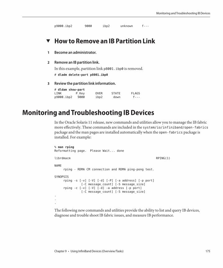
p9000.ibp2 9000 ibp2 unknown f---
▼ How to Remove an IB Partition LinkBecome an administrator.
Remove an IB partition link.In this example, partition link p8001.ibp0 is removed.# dladm delete-part p8001.ibp0
Review the partition link information.# dldam show-part
LINK P_Key OVER STATE FLAGS
p9000.ibp2 9000 ibp2 down f---
Monitoring and Troubleshooting IB DevicesIn the Oracle Solaris 11 release, new commands and utilities allow you to manage the IB fabricmore effectively. These commands are included in the system/io/infiniband/open-fabricspackage and the man pages are installed automatically when the open-fabrics package isinstalled. For example:
% man rping
Reformatting page. Please Wait... done
librdmacm RPING(1)
NAME
rping - RDMA CM connection and RDMA ping-pong test.
SYNOPSIS
rping -s [-v] [-V] [-d] [-P] [-a address] [-p port]
[-C message_count] [-S message_size]
rping -c [-v] [-V] [-d] -a address [-p port]
[-C message_count] [-S message_size]
.
.
.
The following new commands and utilities provide the ability to list and query IB devices,diagnose and trouble shoot IB fabric issues, and measure IB performance.
1
2
3
Monitoring and Troubleshooting IB Devices
Chapter 9 • Using InfiniBand Devices (Overview/Tasks) 175

TABLE 9–1 General IB Monitoring Commands
Command Description
ibv_asyncwatch Monitors InfiniBand asynchronous events
ibv_devices or ibv_devinfo Lists InfiniBand devices or device information
ibv_rc_pingpong, ibv_srq_pingpong,or ibv_ud_pingpong
Tests node to node connectivity by using RC connection, SRQs, orUD connection
mckey Tests RDMA CM multicast setup and simple data transfer
rping Tests RDMA CM connection and attempts RDMA ping-pong
ucmatose Tests RDMA CM connection and attempts simple ping-pong
udaddy Tests RDMA CM datagram setup and attempts simple ping-pong
TABLE 9–2 General IB Performance Testing Commands
Command Description
rdma_bw or rdma_lat
Tests RDMA write transactions for streaming bandwidth orlatency
ib_read_bw or ib_read_lat Tests RDMA read transactions for bandwidth or latency
ib_send_bw or ib_send_lat Tests RDMA send transactions for bandwidth or latency
ib_write_bw or ib_write_bw_postlist
Tests RDMA write transactions for bandwidth that displays oneI/O request at a time or post list bandwidth that displays a list ofI/O requests
ib_write_lat Tests RDMA write transactions for latency
ib_clock_test Tests accuracy of system clock
qperf Measures socket and RDMA performance
TABLE 9–3 RDS Monitoring and Testing Tools
Command Description
rds-info Displays RDS kernel module information
rds-ping Determines if remote node over RDS is reachable
rds-stress Sends message between processes over RDS sockets
Monitoring and Troubleshooting IB Devices
Oracle Solaris Administration: Devices and File Systems • February 2012176

TABLE 9–4 Fabric Diagnostic Tools
Command Description
ibdiagnet Performs diagnostic check of the entire fabric
ibaddr Queries InfiniBand address or addresses
ibnetdiscover Discovers remote InfiniBand topology
ibping Validates connectivity between IB nodes
ibportstate Queries physical port state and link speed of an IB port
ibroute Displays InfiniBand switch forwarding tables
ibstat or ibsysstatQuery status of InfiniBand device or devices or the status of asystem on an IB address
ibtracert Traces an IB path
perfquery or saquery Queries IB port counters or sIB subnet administration attributes
sminfo Queries IB SMInfo attribute
smpquery or smpdump Queries or dumps IB subnet management attributes
ibcheckerrors or ibcheckerrs Validates IB port (or node) or IB subnet and reports errors
ibchecknet, ibchecknode, oribcheckport
Validates IB subnet, node, or port and reports errors
ibcheckportstate,
ibcheckportwidth, ibcheckstate, or
ibcheckwidth
Validates IB port that are link up but not active, ports for 1x (2.0Gbps) link width, ports in IB subnet that are link up but not active,or lx links in IB subnet
ibclearcounters or ibclearerrors Clears port counters or error counters in IB subnet
ibdatacounters or ibdatacounts Queries for data counters in IB subnet or IB port data counters
ibdiscover.pl Annotates and compares IB topology
ibhosts Displays IB host nodes in topology
iblinkinfo.pl or iblinkinfo Displays link information for all links in the fabric
ibnodes Displays IB nodes in topology
ibprintca.pl
Displays either the CA specified or the list of CAs from theibnetdiscover output
ibprintrt.pl
Displays either only the router specified or a list of routers from theibnetdiscover output
ibprintswitch.pl
Displays either the switch specified or a list of switches from theibnetdiscover output
Monitoring and Troubleshooting IB Devices
Chapter 9 • Using InfiniBand Devices (Overview/Tasks) 177

TABLE 9–4 Fabric Diagnostic Tools (Continued)Command Description
ibqueryerrors.pl Queries and report non-zero IB port counters
ibrouters Displays IB router nodes in topology
ibstatus Queries basic status of IB devices
ibswitches Displays IB switch nodes in topology
ibswportwatch.pl
Polls the counters on the specified switch or port and report rate ofchange information
set_nodedesc.sh
Sets or displays node description string for IB Host ControllerAdapters (HCA)s
dump2psl.pl
Dumps PSL file based on opensm output file that is used for creditloop checking
dump2slvl.pl
Dumps SLVL file based on opensm output file that is used for creditloop checking
ibis An extended TCL shell for IB management inband services
Monitoring and Troubleshooting IB Devices
Oracle Solaris Administration: Devices and File Systems • February 2012178

Managing Disks (Overview)
This chapter provides overview information about Oracle Solaris disk slices and introduces theformat utility.
This is a list of overview information in this chapter.
■ “What's New in Disk Management?” on page 179■ “Where to Find Disk Management Tasks” on page 185■ “Overview of Disk Management” on page 186■ “Disk Terminology” on page 186■ “About Disk Labels” on page 186■ “About Disk Slices” on page 190■ “format Utility” on page 191■ “Partitioning a Disk” on page 194
For instructions on how to add a disk to your system, see Chapter 12, “SPARC: Setting Up Disks(Tasks),” or Chapter 13, “x86: Setting Up Disks (Tasks).”
What's New in Disk Management?This section describes new disk management features in the Oracle Solaris release.
■ “Identifying Devices by Physical Locations” on page 180■ “Two-Terabyte Disk Support for Installing and Booting the Oracle Solaris OS” on page 183■ “iSNS Support in the Solaris iSCSI Target and Initiator” on page 184■ “Solaris COMSTAR iSCSI Support” on page 184■ “x86: Disk Management in the GRUB Boot Environment” on page 184■ “Support for SCSI Disks That are Larger Than 2 Terabytes” on page 185
10C H A P T E R 1 0
179

Identifying Devices by Physical LocationsOracle Solaris 11: In this release, the /dev/chassis directory provides device names thatincludes physical locations. You can use this information to help you identify where devices arephysically located if they need to be replaced or changed. You can use the following commandsto display information by chassis, receptacle, and occupant values for the devices on yoursystem:■ diskinfo – Use this command to display general information about physical disk locations■ format – Use this command to display physical disk location information for disks when
reviewing partition tables or relabeling■ prtconf -l – Use this command to display system configuration information that includes
physical disk location information■ zpool status -l – Use this command to display physical disk location information for pool
devices
In addition, you can use the fmadm add-alias command to include a disk alias name that helpsyou identify the physical location of disks in your environment. For example:
# fmadm add-alias SUN-Storage-J4200.0912QAJ001 J4200@RACK10:U26-27
# fmadm add-alias SUN-Storage-J4200.0905QAJ00E J4200@RACK10:U24-25
These aliases can then be displayed with the preceding commands to display physical disklocation information. For example:
$ diskinfo
D:devchassis-path c:occupant-compdev
----------------------------------------------------- ------------------
/dev/chassis/J4200@RACK10:U24-25/SCSI_Device__0/disk c1t13d0
/dev/chassis/J4200@RACK10:U24-25/SCSI_Device__1/disk c1t14d0
/dev/chassis/J4200@RACK10:U24-25/SCSI_Device__2/disk c1t2d0
/dev/chassis/J4200@RACK10:U24-25/SCSI_Device__3/disk c1t3d0
/dev/chassis/J4200@RACK10:U24-25/SCSI_Device__4/disk c1t15d0
/dev/chassis/J4200@RACK10:U24-25/SCSI_Device__5/disk c1t16d0
/dev/chassis/J4200@RACK10:U24-25/SCSI_Device__6/disk c1t6d0
/dev/chassis/J4200@RACK10:U24-25/SCSI_Device__7/disk c1t7d0
/dev/chassis/J4200@RACK10:U24-25/SCSI_Device__8/disk c1t17d0
/dev/chassis/J4200@RACK10:U24-25/SCSI_Device__9/disk c1t18d0
/dev/chassis/J4200@RACK10:U24-25/SCSI_Device__10/disk c1t10d0
Determine where a particular disk is located:
% diskinfo -c c6t11d0
D:devchassis-path c:occupant-compdev
-------------------------------------------------------------- ------------------
/dev/chassis/SUN-Storage-J4400/SCSI_Device__11/disk c6t11d0
In this example, the /dev/chassis disk name includes an alias name that helps you locate thedevice in your environment.
The following diskinfo example shows how to display a specific disk's physical location.
What's New in Disk Management?
Oracle Solaris Administration: Devices and File Systems • February 2012180

$ diskinfo -c c6t11d0 -o cp
c:occupant-compdev p:occupant-paths
------------------ -----------------------------------------------------
c6t11d0 /devices/pci@0,0/pci8086,3604@1/pci1000,3150@0/sd@b,0
If you want to identify how many disks of a certain type are included on the system, usediskinfo syntax similar to the following:
$ diskinfo -n SEAGATE ST31000N-SU0B-931.51GB -o Dcf
D:devchassis-path t:occupant-type c:occupant-compdev
---------------------------------------------------- --------------- ------------------
/dev/chassis/colab5@RACK10_24-25/SCSI_Device__0/disk disk c0t13d0
/dev/chassis/colab5@RACK10_24-25/SCSI_Device__1/disk disk c0t14d0
/dev/chassis/colab5@RACK10_24-25/SCSI_Device__2/disk disk c0t2d0
/dev/chassis/colab5@RACK10_24-25/SCSI_Device__3/disk disk c0t1d0
/dev/chassis/colab5@RACK10_24-25/SCSI_Device__4/disk disk c0t15d0
/dev/chassis/colab5@RACK10_24-25/SCSI_Device__5/disk disk c0t16d0
/dev/chassis/colab5@RACK10_24-25/SCSI_Device__6/disk disk c0t6d0
/dev/chassis/colab5@RACK10_24-25/SCSI_Device__7/disk disk c0t7d0
/dev/chassis/colab5@RACK10_24-25/SCSI_Device__8/disk disk c0t17d0
/dev/chassis/colab5@RACK10_24-25/SCSI_Device__9/disk disk c0t18d0
/dev/chassis/colab5@RACK10_24-25/SCSI_Device__10/disk disk c0t10d0
Note – The diskinfo command require that chassis support SES diagnostic page 0xa(Additional Element Status) and must set the Element Index Present (EIP) bit to 1. Enclosuresthat do not meet this criteria will not be fully enumerated, and thus, will not be properlyrepresented.
The format command has been updated to provide physical device location information. Forexample:
# format
.
.
.
18. c0t4d0 <SEAGATE-ST345056SSUN450G-081C-419.19GB>
/pci@0,600000/pci@0/pci@9/LSILogic,sas@0/sd@4,0
/dev/chassis/colab5@RACK10_26-27/SCSI_Device__6/disk
19. c0t27d0 <ATA-SEAGATE ST35000N-3AZQ-465.76GB>
/pci@0,600000/pci@0/pci@9/LSILogic,sas@0/sd@1b,0
/dev/chassis/colab5@RACK10_26-27/SCSI_Device__7/disk
20. c0t23d0 <ATA-SEAGATE ST31000N-SU0B-931.51GB>
/pci@0,600000/pci@0/pci@9/LSILogic,sas@0/sd@17,0
/dev/chassis/colab5@RACK10_26-27/SCSI_Device__8/disk
21. c0t24d0 <ATA-SEAGATE ST31000N-SU0B-931.51GB>
/pci@0,600000/pci@0/pci@9/LSILogic,sas@0/sd@18,0
/dev/chassis/colab5@RACK10_26-27/SCSI_Device__9/disk
Use the prtconf -l to display the physical device location information. For example:
$ prtconf -l | more
System Configuration: Oracle Corporation sun4v
Memory size: 32640 Megabytes
What's New in Disk Management?
Chapter 10 • Managing Disks (Overview) 181

System Peripherals (Software Nodes):
SUNW,SPARC-Enterprise-T5220 location: /dev/chassis/SUN-Storage-J4400.0918QAKA24/SCSI_Device__0/disk
.
.
.
pci, instance #15 location: /dev/chassis/SUN-Storage-J4400.0918QAKA24/SCSI_Device__0/disk
LSILogic,sas, instance #1 location: /dev/chassis/SUN-Storage-J4400.0918QAKA24/SCSI_Device__0/disk
smp, instance #0 (driver not attached)
sd, instance #2 location: /dev/chassis/SUN-Storage-J4400.0918QAKA24/SCSI_Device__0/disk
sd, instance #4 location: /dev/chassis/SUN-Storage-J4400.0918QAKA24/SCSI_Device__1/disk
sd, instance #5 location: /dev/chassis/SUN-Storage-J4400.0918QAKA24/SCSI_Device__2/disk
sd, instance #6 location: /dev/chassis/SUN-Storage-J4400.0918QAKA24/SCSI_Device__3/disk
sd, instance #7 location: /dev/chassis/SUN-Storage-J4400.0918QAKA24/SCSI_Device__4/disk
sd, instance #8 location: /dev/chassis/SUN-Storage-J4400.0918QAKA24/SCSI_Device__5/disk
sd, instance #9 location: /dev/chassis/SUN-Storage-J4400.0918QAKA24/SCSI_Device__6/disk
sd, instance #10 location: /dev/chassis/SUN-Storage-J4400.0918QAKA24/SCSI_Device__7/disk
sd, instance #11 location: /dev/chassis/SUN-Storage-J4400.0918QAKA24/SCSI_Device__8/disk
sd, instance #12 location: /dev/chassis/SUN-Storage-J4400.0918QAKA24/SCSI_Device__9/disk
sd, instance #13 location: /dev/chassis/SUN-Storage-J4400.0918QAKA24/SCSI_Device__10/disk
sd, instance #14 location: /dev/chassis/SUN-Storage-J4400.0918QAKA24/SCSI_Device__11/disk
Use the zpool status -l option to display physical device location information. For example:
% zpool status -l export
pool: export
state: ONLINE
scan: resilvered 379G in 8h31m with 0 errors on Thu Jan 27 23:10:20 2011
config:
NAME STATE READ WRITE CKSUM
export ONLINE 0 0 0
mirror-0 ONLINE 0 0 0
/dev/chassis/SUN-Storage-J4400.rack22/SCSI_Device__2/disk ONLINE 0 0 0
/dev/chassis/SUN-Storage-J4400.rack22/SCSI_Device__3/disk ONLINE 0 0 0
mirror-1 ONLINE 0 0 0
/dev/chassis/SUN-Storage-J4400.rack22/SCSI_Device__4/disk ONLINE 0 0 0
/dev/chassis/SUN-Storage-J4400.rack22/SCSI_Device__5/disk ONLINE 0 0 0
mirror-2 ONLINE 0 0 0
/dev/chassis/SUN-Storage-J4400.rack22/SCSI_Device__6/disk ONLINE 0 0 0
/dev/chassis/SUN-Storage-J4400.rack22/SCSI_Device__7/disk ONLINE 0 0 0
mirror-3 ONLINE 0 0 0
/dev/chassis/SUN-Storage-J4400.rack22/SCSI_Device__8/disk ONLINE 0 0 0
/dev/chassis/SUN-Storage-J4400.rack22/SCSI_Device__9/disk ONLINE 0 0 0
mirror-4 ONLINE 0 0 0
/dev/chassis/SUN-Storage-J4400.rack22/SCSI_Device__10/disk ONLINE 0 0 0
/dev/chassis/SUN-Storage-J4400.rack22/SCSI_Device__11/disk ONLINE 0 0 0
spares
/dev/chassis/SUN-Storage-J4400.rack22/SCSI_Device__0/disk AVAIL
/dev/chassis/SUN-Storage-J4400.rack22/SCSI_Device__1/disk AVAIL
errors: No known data errors
What's New in Disk Management?
Oracle Solaris Administration: Devices and File Systems • February 2012182

Multiple Disk Sector Size SupportOracle Solaris 11: Previous Solaris releases supported a disk sector size of 512 bytes. In thisrelease, disks with sector sizes of 512 bytes, 1024 bytes, 2048 bytes, or 4096 bytes are supported.Large sector disks provide greater disk capacity, higher reliability, and greater efficiency for datatransfer and faster drive maintenance.
In this Oracle Solaris release, the only supported file system that can be used on a large sectordisk is a non-root ZFS file system. For more information about using a large sector disk as aCOMSTAR target, see Chapter 14, “Configuring Storage Devices With COMSTAR.”
The ability to boot and install from a large sector disk is not currently supported.
Two-Terabyte Disk Support for Installing and Bootingthe Oracle Solaris OSOracle Solaris 11: In previous Solaris releases, you could not install and boot the Solaris OSfrom a disk that was greater than 1 TB in size. In this Solaris release, you can install and boot theSolaris OS from a disk that is up to 2 TB in size. In previous releases, you also had to use an EFIlabel for a disk that is larger than 1 TB. In this release, you can use the VTOC label on any sizedisk, but the addressable space by the VTOC is limited to 2 TB.
The Oracle Solaris disk drivers and disk utilities have been updated to provide the followingsupport:■ Installing and booting the Oracle Solaris OS on a two-terabyte disk must be connected to a
system with a minimum of 1.5 GB of memory.■ You can use the format -e utility to label a disk of any size with a VTOC label, but the
addressable space is limited to 2 TB.■ The default label that is used by the format utility and the installation software for a disk
that is less than 2 TB in size is a VTOC label.■ You can use the fdisk utility on a disk that is greater than 1 TB on x86 systems. Support is
added for up to 2-TB partitions in the MBR for non-EFI partition types. This support meansthat Solaris partitions can go up to 2 TB. Other non-EFI partitions may be subject to a limitdepending on partition type.When the fdisk utility is run on a disk that is greater than 2 TB in size, a warning message isdisplayed to indicate that you cannot create a non-EFI partition that is greater than 2 TB.
Keep in mind that you cannot move a disk over 1 TB with a legacy MBR or a legacy VTOC to aprevious Solaris release. EFI labeled disks continue to work as in previous Solaris releases.
For more information about the EFI label changes in this release, see “EFI Disk Label” onpage 187.
What's New in Disk Management?
Chapter 10 • Managing Disks (Overview) 183

iSNS Support in the Solaris iSCSI Target and InitiatorOracle Solaris 11: This Solaris release provides support for the Internet Storage Name Service(iSNS) protocol in the Solaris iSCSI target and initiator software. The iSNS protocol allows forthe automated discovery, management, and configuration of iSCSI devices on a TCP/IPnetwork.
See the following resources for step-by-step instructions:■ For information about configuring the Oracle Solaris iSCSI target to use a third-party iSNS
server, see Chapter 14, “Configuring Storage Devices With COMSTAR.”■ For information about configuring the Solaris iSCSI target with a Solaris iSNS server, see
Chapter 15, “Configuring and Managing the Oracle Solaris Internet Storage Name Service(iSNS),” and isnsadm(1M).
Solaris COMSTAR iSCSI SupportOracle Solaris 11: iSCSI is an Internet Protocol (IP)-based storage networking standard forlinking data storage subsystems. By carrying SCSI commands over IP networks, the iSCSIprotocol enables you to mount disk devices, from across the network, onto your local system.On your local system, you can use the devices like block devices.
Common Multiprotocol SCSI TARget, or COMSTAR, a software framework enables you toconvert any Oracle Solaris 11 host into a SCSI target device that can be accessed over a storagenetwork by initiator hosts
For more information, see Chapter 14, “Configuring Storage Devices With COMSTAR.”
x86: Disk Management in the GRUB Boot EnvironmentOracle Solaris 11: The GRUB boot menu has replaced the previous method for booting an x86system. In the area of disk management, you use the GRUB interface when booting from analternative device to replace a system disk or when installing the bootblocks.
The GRUB boot environment provides the following features:■ Network boot – Boot from the network by pressing the F12 key during the BIOS
configuration phase.■ Single-user boot – Boot to single-user mode by selecting this option from the Solaris failsafe
boot menu:
kernel /platform/i86pc/multiboot
Then, use the e (edit) option to add the -s single-user option. For example:
kernel /platform/i86pc/multiboot -s
What's New in Disk Management?
Oracle Solaris Administration: Devices and File Systems • February 2012184

Press return and then press the b key to boot the system. Press control-D to boot the systemback to multiuser mode.
In the GRUB environment, you cannot use the fmthard command to install the boot blocksautomatically when run on an x86 system. You must install the boot blocks separately.
For detailed feature information and instructions on using the new GRUB based booting on x86systems, see Booting and Shutting Down Oracle Solaris on x86 Platforms.
This feature is not available on SPARC systems.
Support for SCSI Disks That are Larger Than 2TerabytesOracle Solaris 11: The SCSI driver, ssd or sd, supports 2 terabytes and greater. The SCSI driver,ssd or sd, is limited to 2 TB in previous Solaris releases.
The format utility can be used to label, configure, and partition these larger disks. Forinformation about using the EFI disk label on large disks and restrictions with the fdisk utility,see “Restrictions of the EFI Disk Label” on page 188.
Where to Find Disk Management TasksUse these references to find step-by-step instructions for managing disks.
Disk Management Task For More Information
Format a disk and examine a disk label. Chapter 11, “Administering Disks (Tasks)”
Add a new disk to a SPARC system. Chapter 12, “SPARC: Setting Up Disks (Tasks)”
Add a new disk to an x86 system. Chapter 13, “x86: Setting Up Disks (Tasks)”
Hot-plug a SCSI or PCI disk. Chapter 6, “Dynamically Configuring Devices(Tasks)”
Where to Find Disk Management Tasks
Chapter 10 • Managing Disks (Overview) 185

Overview of Disk ManagementManaging disks in the Oracle Solaris OS usually involves setting up the system and running theOracle Solaris installation program to create the appropriate disk slices and file systems and toinstall the Oracle Solaris OS. Occasionally, you might need to use the format utility to add anew disk drive or replace a defective disk drive.
Disk TerminologyBefore you can effectively use the information in this section, you should be familiar with basicdisk architecture. In particular, you should be familiar with the following terms:
Disk Term Description
Track A concentric ring on a disk that passes under a single stationary diskhead as the disk rotates.
Cylinder The set of tracks with the same nominal distance from the axis aboutwhich the disk rotates.
Sector Section of each disk platter. A sector holds 512 bytes.
Block A data storage area on a disk. A disk block is 512 bytes.
Disk controller A chip and its associated circuitry that controls the disk drive.
Disk label The first sector of a disk that contains disk geometry and partitioninformation.
Device driver A kernel module that controls a hardware or virtual device.
For additional information, see the product information from your disk's manufacturer.
About Disk LabelsA special area of every disk is set aside for storing information about the disk's controller,geometry, and slices. This information is called the disk's label. Another term that is used todescribed the disk label is the VTOC (Volume Table of Contents) on a disk with a VTOC label.To label a disk means to write slice information onto the disk. You usually label a disk after youchange its slices.
The Oracle Solaris release supports the following two disk labels:
■ SMI – The traditional VTOC label for disks that are less than 2 TB in size.■ EFI – Provides support for disks that are larger than 2 TB. The Extensible Firmware
Interface GUID Partition Table (EFI GPT) disk label is also available for disks less than 2 TB.
Overview of Disk Management
Oracle Solaris Administration: Devices and File Systems • February 2012186

If you fail to label a disk after you create slices, the slices will be unavailable because the OS hasno way of “knowing” about the slices.
EFI Disk LabelThe EFI label provides support for physical disks and virtual disk volumes that are greater than2 TB in size. This release also includes updated disk utilities for managing disks greater than 2TB in size.
The following file system products support file systems greater than 1 TB in size:
■ The Oracle Solaris ZFS file system supports file systems greater than 1 TB in size.
The VTOC label is still available for disks less than 2 terabytes in size. If you are only using diskssmaller than 2 TB on your systems, managing disks will be the same as in previous Solarisreleases. In addition, you can use the format-e command to label a disk 2 TB in size or less withan EFI label. For more information, see Example 11–5.
You can use the format -e command to apply an EFI label to a disk if the system is running theappropriate Oracle Solaris release. However, you should review the important information in“Restrictions of the EFI Disk Label” on page 188 before attempting to apply an EFI label.
You can also use the format -e command to reapply a VTOC label if the EFI label is no longerneeded. For example:
# format -e
Specify disk (enter its number): 2
selecting c0t5d0
[disk formatted]
.
.
.
format> label
[0] SMI Label
[1] EFI Label
Specify Label type[1]: 0
Warning: This disk has an EFI label. Changing to SMI label will erase all
current partitions.
Continue? yes
Auto configuration via format.dat[no]?
Auto configuration via generic SCSI-2[no]?
format> quit
Caution – Keep in mind that changing disk labels will destroy any data on the disk.
Overview of Disk Management
Chapter 10 • Managing Disks (Overview) 187

Comparison of the EFI Label and the VTOC LabelThe EFI disk label differs from the VTOC disk label in the following ways:
■ Provides support for disks greater than 2 terabytes in size.■ Provides usable slices 0-6, where slice 2 is just another slice.■ Partitions (or slices) cannot overlap with the primary or backup label, nor with any other
partitions. The size of the EFI label is usually 34 sectors, so partitions usually start at sector34. This feature means that no partition can start at sector zero (0).
■ No cylinder information is stored in the EFI label. Sizes are reported in blocks.■ Information that was stored in the alternate cylinders area, the last two cylinders of the disk,
is now stored in slice 8.■ If you use the format utility to change partition sizes, the unassigned partition tag is
assigned to partitions with sizes equal to zero. By default, the format utility assigns the usrpartition tag to any partition with a size greater than zero. You can use the partition changemenu to reassign partition tags after the partitions are changed. However, you cannotchange a partition with a non-zero size to the unassigned partition tag.
Restrictions of the EFI Disk LabelKeep the following restrictions in mind when determining whether using disks greater than 1terabyte is appropriate for your environment:
■ Layered software products intended for systems with VTOC-labeled disks might beincapable of accessing a disk with an EFI disk label.
■ A disk with an EFI label is not recognized on systems running previous Solaris releases.■ You cannot boot from a disk with an EFI disk label.■ On x86 based systems, you can use the fdisk command on a disk with an EFI label that is
greater than 2 TB in size.■ Use the format utility to partition disks with EFI labels.■ The EFI specification prohibits overlapping slices. The entire disk is represented by cxtydz.■ The EFI disk label provides information about disk or partition sizes in sectors and blocks,
but not in cylinders and heads.■ The following format options are either not supported or are not applicable on disks with
EFI labels:■ The save option is not supported because disks with EFI labels do not need an entry in
the format.dat file.■ The backup option is not applicable because the disk driver finds the primary label and
writes it back to the disk.
Overview of Disk Management
Oracle Solaris Administration: Devices and File Systems • February 2012188

Support for EFI-Labeled Disks on x86 SystemsOracle Solaris support for the EFI disk label is available on x86 systems. Use the followingcommand to add an EFI label on an x86 system:
# format -e
> [0] SMI Label
> [1] EFI Label
> Specify Label type[0]: 1
> WARNING: converting this device to EFI labels will erase all current
> fdisk partition information. Continue? yes
Previous label information is not converted to the EFI disk label.
You will have to recreate the label's partition information manually with the format command.You cannot use the fdisk command on a disk with an EFI label that is 2 terabytes in size. If thefdisk command is run on disk that is greater than 2 TB in size to create a Solaris partition, theSolaris partition is limited to 2 TB. For more information about EFI disk labels, see thepreceding section.
Installing a System With an EFI-Labeled DiskAn Oracle Solaris root pool disk must have an SMI label. The Oracle Solaris 11 installationutilities automatically relabel any disk that is selected as a root pool disk with an SMI label.
Managing Disks With EFI Disks LabelsUse the following table to locate information on managing disks with EFI disk labels.
Task For More Information
If the system is already installed, connect the disk tothe system.
“SPARC: Setting up Disks for ZFS File Systems (TaskMap)” on page 217 or “x86: Setting Up Disks for ZFSFile Systems (Task Map)” on page 227
Create a ZFS file system. “SPARC: Setting Up Disks for ZFS File Systems” onpage 218 or “x86: Setting Up Disks for ZFS FileSystems” on page 228
Troubleshooting Problems With EFI Disk LabelsUse the following error messages and solutions to troubleshoot problems with EFI-labeleddisks.
SolutionBoot a system running SPARC or x86 kernel with a disk greater than 1 terabyte.
Overview of Disk Management
Chapter 10 • Managing Disks (Overview) 189

Error Message
Dec 3 09:12:17 holoship scsi: WARNING: /sbus@a,0/SUNW,socal@d,10000/
sf@1,0/ssd@w50020f23000002a4,0 (ssd1):
Dec 3 09:12:17 holoship corrupt label - wrong magic number
CauseYou attempted to add a disk to a system running an older Solaris release.
SolutionAdd the disk to a system running the Solaris release that supports the EFI disk label.
About Disk SlicesFiles stored on a disk are contained in file systems. Each file system on a disk is assigned to aslice, which is a group of sectors set aside for use by that file system. Each disk slice appears tothe Oracle Solaris OS (and to the system administrator) as though it were a separate disk drive.
For information about file systems, see Chapter 17, “Managing File Systems (Overview).”
Note – Slices are sometimes referred to as partitions. Certain interfaces, such as the formatutility, refer to slices as partitions.
When setting up slices, remember these rules:
■ Each disk slice holds only one file system.■ No file system can span multiple slices.
Slices are set up slightly differently on SPARC and x86 platforms. The following tablesummarizes the differences.
TABLE 10–1 Slice Differences on SPARC and x86 Platforms
SPARC Platform x86 Platform
The entire disk is devoted to Oracle Solaris OS. Disk is divided into fdisk partitions, one fdiskpartition per operating system.
VTOC – The disk is divided into 8 slices, numbered0-7.
EFI – The disk is divided into 7 slices, numbered 0-6.
VTOC – The Solaris fdisk partition is divided into 10slices, numbered 0–9.
EFI – The disk is divided into 7 slices, numbered 0-6
Disk SlicesOn a system with ZFS file systems, disk slices are only required for the ZFS root pool thatcontains the ZFS root file system. In general, the ZFS root pool is contained in slice 0. The ZFS
Overview of Disk Management
Oracle Solaris Administration: Devices and File Systems • February 2012190

root pool must exist on a slice or mirrored slices because of a long-standing boot limitation. Fornon-root storage pools, you can use whole disks. ZFS file systems do not correspond to specificdisk slices. Managing whole disks is easier than managing disks with slices.
On x86 systems:
■ Disks are divided into fdisk partitions. An fdisk partition is a section of the disk that isreserved for a particular operating system, such as the Oracle Solaris OS.
■ The Oracle Solaris OS places ten slices, numbered 0-9, on a Solaris fdisk partition.
Note – On a disk with a VTOC label, do not modify slice or use slice 2 to store a file system. Theinstallgrub command does not work correctly if slice 2 is modified in any way.
Using Raw Data SlicesThe disk label is stored in block 0 of each disk. So, third-party database applications that createraw data slices must not start at block 0. Otherwise, the disk label will be overwritten, and thedata on the disk will be inaccessible.
Do not use the following areas of the disk for raw data slices, which are sometimes created bythird-party database applications:
■ Block 0 where the disk label is stored■ Slice 2, which represents the entire disk with a VTOC label
format UtilityRead the following overview of the format utility and its uses before proceeding to the “how-to”or reference sections.
The format utility is a system administration tool that is used to prepare hard disk drives for useon your Oracle Solaris system.
The following table shows the features and associated benefits that the format utility provides.
TABLE 10–2 Features and Benefits of the format Utility
Feature Benefit
Searches your system for allattached disk drives
Reports on the following:■ Target location■ Disk geometry■ Whether the disk is formatted■ If the disk has mounted partitions
Retrieves disk labels Convenient for repair operations
Overview of Disk Management
Chapter 10 • Managing Disks (Overview) 191

TABLE 10–2 Features and Benefits of the format Utility (Continued)Feature Benefit
Repairs defective sectors Allows administrators to repair disk drives with recoverable errorsinstead of sending the drive back to the manufacturer
Formats and analyzes a disk Creates sectors on the disk and verifies each sector
Partitions a disk Divides a disk into slices. ZFS file systems do not correspond to diskslices except for the ZFS root pool.
Labels a disk Writes disk name and configuration information to the disk for futureretrieval (usually for repair operations)
The format utility options are described in Chapter 16, “The format Utility (Reference).”
When to Use the format UtilityDisk drives are partitioned and labeled by the Oracle Solaris installation utility when you installthe Oracle Solaris release. You can use the format utility to do the following:
■ Display slice information■ Partition a disk■ Add a disk drive to an existing system■ Format a disk drive■ Label a disk■ Repair a disk drive■ Analyze a disk for errors
The main reason a system administrator uses the format utility is to partition a disk. Thesesteps are covered in Chapter 12, “SPARC: Setting Up Disks (Tasks),” and Chapter 13, “x86:Setting Up Disks (Tasks).”
See the following section for guidelines on using the format utility.
Overview of Disk Management
Oracle Solaris Administration: Devices and File Systems • February 2012192

Guidelines for Using the format Utility
TABLE 10–3 format Utility Guidelines
Task Guidelines For More Information
Format a disk. ■ Any existing data is destroyed when youreformat a disk.
■ The need for formatting a disk drive hasdecreased as more and more manufacturers shiptheir disk drives formatted and partitioned. Youmight not need to use the format utility whenyou add or replace a disk drive to an existingsystem.
■ If a disk has been relocated and is displayingmany disk errors, you can attempt to relabel it.
“How to Format a Disk” onpage 203 or “How to Label aDisk” on page 206
Set up a disk thatcontains a ZFS rootfile system.
In a non-redundant configuration, a ZFS root filesystem data from the damaged disk must be restoredfrom a backup medium. Otherwise, the system willhave to be reinstalled by using the installation utility.
“SPARC: How to Set Up a Diskfor a ZFS Root File System” onpage 219 or “x86: How to Set Upa Disk for a ZFS Root FileSystem” on page 229, or, if thesystem must be reinstalled,Installing Oracle Solaris 11Systems
Create a disk slice fora root pool.
■ The best way to use a ZFS storage pool is bycreating a pool with whole disks.
■ If a disk is intended to be used for a root pool,you must create a disk slice. This islong-standing boot limitation.
“SPARC: How to Create a DiskSlice for a ZFS Root File System”on page 220 or “x86: How toCreate a Disk Slice for a ZFSRoot File System” on page 230
Set up a disk thatcontains a ZFS filesystem.
A disk that is used for a non-root ZFS file systemusually contains space for user or data files. You canattach or add a another disk to a root pool or anon-root pool for more disk space.
“SPARC: How to Set Up a Diskfor a ZFS File System” onpage 224 or “x86: How to Set Upa Disk for a ZFS File System” onpage 234
Formatting a DiskIn most cases, disks are formatted by the manufacturer or reseller. So, they do not need to bereformatted when you install the drive. To determine if a disk is formatted, use the formatutility. For more information, see “How to Determine if a Disk Is Formatted” on page 202.
If you determine that a disk is not formatted, use the format utility to format the disk.
When you format a disk, you accomplish two steps:
Overview of Disk Management
Chapter 10 • Managing Disks (Overview) 193

■ The disk media is prepared for use.■ A list of disk defects based on a surface analysis is compiled.
Caution – Formatting a disk is a destructive process because it overwrites data on the disk. Forthis reason, disks are usually formatted only by the manufacturer or reseller. If you think diskdefects are the cause of recurring problems, you can use the format utility to do a surfaceanalysis. However, be careful to use only the commands that do not destroy data. For details, see“How to Format a Disk” on page 203.
A small percentage of total disk space that is available for data is used to store defect andformatting information. This percentage varies according to disk geometry, and decreases asthe disk ages and develops more defects.
Formatting a disk might take anywhere from a few minutes to several hours, depending on thetype and size of the disk.
Partitioning a DiskThe format utility is most often used by system administrators to partitioning a disk. The stepsare as follows:
■ Determining which slices are needed■ Determining the size of each slice or partition■ Using the format utility to partition the disk■ Labeling the disk with new partition information■ Creating the file system for each partition
The easiest way to partition a disk is to use the modify command from the partition menu of theformat utility. The modify command allows you to create partitions by specifying the size ofeach partition without having to keep track of the starting cylinder boundaries. The modifycommand also keeps tracks of any disk space that remains in the “free hog” slice.
Partition Table TerminologyAn important part of the disk label is the partition table. The partition table identifies a disk'sslices, the slice boundaries (in cylinders), and the total size of the slices. You can display a disk'spartition table by using the format utility. The following describes partition table terminology.
Partitioning a Disk
Oracle Solaris Administration: Devices and File Systems • February 2012194

TABLE 10–4 Partition Table Terminology
Partition Term Value Description
Number 0–7 VTOC – Partitions or slices, numbered 0–7.
EFI – Partitions or slices, numbered 0–6.
Tag 0=UNASSIGNED 1=BOOT 2=ROOT
3=SWAP 4=USR 5=BACKUP
7=VAR 8=HOME 11=RESERVED
A numeric value that usually describes the file systemmounted on this partition.
Flags wm The partition is writable and mountable.
wu rm The partition is writable and unmountable. This stateis the default for partitions that are dedicated for swapareas. (However, the mount command does not checkthe “not mountable” flag.)
rm The partition is read only and mountable.
Partition flags and tags are assigned by convention and require no maintenance.
For more information on displaying the partition table, see the following references:
■ “Displaying Partition Table Information” on page 195■ “How to Display Disk Slice Information” on page 204■ “How to Examine a Disk Label” on page 211
Displaying Partition Table InformationThe following format utility output shows an example of a partition table from a 74-GB diskwith a VTOC label displayed:
Total disk cylinders available: 38756 + 2 (reserved cylinders)
Part Tag Flag Cylinders Size Blocks
0 root wm 3 - 2083 4.00GB (2081/0/0) 8390592
1 swap wu 2084 - 3124 2.00GB (1041/0/0) 4197312
2 backup wm 0 - 38755 74.51GB (38756/0/0) 156264192
3 unassigned wm 0 0 (0/0/0) 0
4 unassigned wm 0 0 (0/0/0) 0
5 unassigned wm 0 0 (0/0/0) 0
6 unassigned wm 0 0 (0/0/0) 0
7 home wm 3125 - 38755 68.50GB (35631/0/0) 143664192
8 boot wu 0 - 0 1.97MB (1/0/0) 4032
9 alternates wu 1 - 2 3.94MB (2/0/0) 8064
partition>
The partition table displayed by the format utility contains the following information.
Partitioning a Disk
Chapter 10 • Managing Disks (Overview) 195

Column Name Description
Part Partition or slice number. See Table 10–4 for a description of this column.
Tag Partition tag. See Table 10–4 for a description of this column.
Flag Partition flag. See Table 10–4 for a description of this column.
Cylinders The starting and ending cylinder number for the slice. Not displayed onEFI-labeled disks.
Size The slice size in MB.
Blocks The total number of cylinders and the total number of sectors per slice. Notdisplayed on EFI-labeled disks.
First Sector EFI – The starting block number. Not displayed on VTOC-labeled disks.
Last Sector EFI – The ending block number. Not displayed on VTOC-labeled disks.
The following is an example of an EFI disk label displayed by using the prtvtoc command.
# prtvtoc /dev/rdsk/c4t1d0s0
* /dev/rdsk/c4t1d0s0 partition map
*
* Dimensions:
* 512 bytes/sector
* 2576941056 sectors
* 2576940989 accessible sectors
*
* Flags:
* 1: unmountable
* 10: read-only
*
* First Sector Last
* Partition Tag Flags Sector Count Sector Mount Directory
0 2 00 34 629145600 629145633
1 4 00 629145634 629145600 1258291233
6 4 00 1258291234 1318633404 2576924637
8 11 00 2576924638 16384 2576941021
The output of the prtvtoc command provides information in the following three sections:
■ Dimensions■ Flags■ Partition Table
prtvtocColumn Name Description
Partition Partition or slice number. For a description of this column, see Table 10–4.
Tag Partition tag. For a description of this column, see Table 10–4.
Flags Partition flag. For a description of this column, see Table 10–4.
Partitioning a Disk
Oracle Solaris Administration: Devices and File Systems • February 2012196

prtvtocColumn Name Description
First Sector The first sector of the slice.
Sector Count The total number of sectors in the slice.
Last Sector The last sector of the slice.
Mount Directory The last mount point directory for the file system.
Using the Free Hog SliceWhen you use the format utility to change the size of one or more disk slices, you designate atemporary slice that will expand and shrink to accommodate the resizing operations.
This temporary slice donates, or “frees,” space when you expand a slice, and receives, or “hogs,”the discarded space when you shrink a slice. For this reason, the donor slice is sometimes calledthe free hog.
The free hog slice exists only during installation or when you run the format utility. There is nopermanent free hog slice during day-to-day operations.
For information on using the free hog slice, see “SPARC: How to Create a Disk Slice for a ZFSRoot File System” on page 220 or “x86: How to Create a Disk Slice for a ZFS Root File System”on page 230.
Partitioning a Disk
Chapter 10 • Managing Disks (Overview) 197

198

Administering Disks (Tasks)
This chapter contains disk administration procedures. Many procedures described in thischapter are optional if you are already familiar with how disks are managed on systems runningthe Oracle Solaris OS.
For information on the procedures associated with administering disks, see “AdministeringDisks (Task Map)” on page 199.
For overview information about disk management, see Chapter 10, “Managing Disks(Overview).”
Administering Disks (Task Map)
Task Description For Instructions
Identify the disks on a system. If you are not sure of the types ofdisks on a system, use the formatutility to identify the disk types.
“How to Identify the Disks on aSystem” on page 200
Format the disk. Determine whether a disk isalready formatted by using theformat utility.
“How to Determine if a Disk IsFormatted” on page 202
In most cases, disks are alreadyformatted. Use the format utility ifyou need to format a disk.
“How to Format a Disk” onpage 203
Display slice information. Display slice information by usingthe format utility.
“How to Display Disk SliceInformation” on page 204
Label the disk. Create the disk label by using theformat utility.
“How to Label a Disk” on page 206
11C H A P T E R 1 1
199

Task Description For Instructions
Examine the disk label. Examine the disk label by using theprtvtoc command.
“How to Examine a Disk Label” onpage 211
Recover a corrupted disk label. You can attempt to recover a disklabel that was damaged due to asystem or power failure.
“How to Recover a Corrupted DiskLabel” on page 212
Identifying Disks on a SystemUse the format utility to discover the types of disks that are connected to a system. You can alsouse the format utility to verify that a disk is known to the system. For detailed information onusing the format utility, see Chapter 16, “The format Utility (Reference).”
▼ How to Identify the Disks on a SystemBecome an administrator.For more information, see “How to Use Your Assigned Administrative Rights” in Oracle SolarisAdministration: Security Services.
Identify the disks that are recognized on the system by using the formatutility.# format
The format utility displays a list of disks that it recognizes under AVAILABLE DISK SELECTIONS.
Identifying the Disks on a System
The following example shows format command output.
# format
AVAILABLE DISK SELECTIONS:
0. c2t0d0 <SUN72G cyl 14087 alt 2 hd 24 sec 424>
/pci@1c,600000/scsi@2/sd@0,0
1. c2t1d0 <SUN72G cyl 14087 alt 2 hd 24 sec 424>
/pci@1c,600000/scsi@2/sd@1,0
2. c2t2d0 <SUN146G cyl 14087 alt 2 hd 24 sec 848>
/pci@1c,600000/scsi@2/sd@2,0
3. c2t3d0 <SUN146G cyl 14087 alt 2 hd 24 sec 848>
/pci@1c,600000/scsi@2/sd@3,0
Specify disk (enter its number):
The output associates a disk's physical and logical device name to the disk's marketing name,which appears in angle brackets <>. See the example below. This method is an easy way toidentify which logical device names represent the disks that are connected to your system. For adescription of logical and physical device names, see “Device Naming Conventions” on page 72.
1
2
Example 11–1
Identifying Disks on a System
Oracle Solaris Administration: Devices and File Systems • February 2012200

The following example uses a wildcard to display the four disks that are connected to acontroller 0.
# format /dev/rdsk/c0t6*
AVAILABLE DISK SELECTIONS:
0. /dev/rdsk/c0t600A0B800022024E000054AC4970A629d0p0 <...>
/scsi_vhci/disk@g600a0b800022024e000054ac4970a629
1. /dev/rdsk/c0t600A0B800022024E000054AE4970A711d0p0 <...>
/scsi_vhci/disk@g600a0b800022024e000054ae4970a711
2. /dev/rdsk/c0t600A0B800022028A000050444970A834d0p0 <....>
/scsi_vhci/disk@g600a0b800022028a000050444970a834
3. /dev/rdsk/c0t600A0B800022028A000050454970A8EAd0p0 <...>
/scsi_vhci/disk@g600a0b800022028a000050454970a8ea
Specify disk (enter its number):
The following example shows how to identify the disk information.
# format
0. c2t0d0 <SUN36G cyl 24620 alt 2 hd 27 sec 107>
/pci@1c,600000/scsi@2/sd@0,0
The output identifies that disk 0 (target 0) is connected to the second SCSI host adapter(scsi@2), which is connected to the second PCI interface (/pci@1c,600000/...). The outputalso associates both the physical and logical device name to the disk's marketing name, SUN36G.
Some disks do not have a marketing name. If the format output does not identify disks by theirmarketing names, then you can use the format utility's type and label features as described inthe following steps to include the disk's marketing name.
The following steps must be done while the disk or system is inactive, which means bootingfrom an installation DVD or the network, unless the disk is currently unused and it will notcontain the Oracle Solaris release. In addition, the final step is to relabel the disk, which canremove any existing partition information or data.
# format
Searching for disks...done
AVAILABLE DISK SELECTIONS:
0. c2t0d0 <SUN36G cyl 24620 alt 2 hd 27 sec 107>
/pci@1c,600000/scsi@2/sd@0,0
1. c2t1d0 <SEAGATE-ST336607LSUN36G-0307-33.92GB>
/pci@1c,600000/scsi@2/sd@1,0
2. c2t2d0 <SEAGATE-ST336607LSUN36G-0507-33.92GB>
/pci@1c,600000/scsi@2/sd@2,0
3. c2t3d0 <drive type unknown>
/pci@1c,600000/scsi@2/sd@3,0
Specify disk (enter its number): 3
selecting c2t3d0
[disk formatted]
format> type
AVAILABLE DRIVE TYPES:
0. Auto configure
1. other
Identifying Disks on a System
Chapter 11 • Administering Disks (Tasks) 201

Specify disk type (enter its number): 0
c2t3d0: configured with capacity of 33.92GB
<SEAGATE-ST336607LSUN36G-0507-33.92GB>
[disk formatted]
format> label
Ready to label disk, continue? yes
format> quit
If the format Utility Does Not Recognize a Disk ...■ Go to Chapter 12, “SPARC: Setting Up Disks (Tasks),” or Chapter 13, “x86: Setting Up Disks
(Tasks).”■ Go to “How to Label a Disk” on page 206.■ Connect the disk to the system by using your disk hardware documentation.
Formatting a DiskDisks are typically formatted by the manufacturer or reseller. They usually do not need to bereformatted when you install the drive.
A disk must be formatted before you can do the following:
■ Write data to the disk. However, most disks are already formatted.■ Use the Oracle Solaris installation utility to install the system.
Caution – Formatting a disk is a destructive process because it overwrites data on the disk. Forthis reason, disks are usually formatted only by the manufacturer or reseller. If you think diskdefects are the cause of recurring problems, you can use the format utility to do a surfaceanalysis. However, be careful to use only the commands that do not destroy data.
▼ How to Determine if a Disk Is FormattedBecome an administrator.For more information, see “How to Use Your Assigned Administrative Rights” in Oracle SolarisAdministration: Security Services.
Invoke the formatutility.# format
A numbered list of disks is displayed.
Type the number of the disk that you want to check.Specify disk (enter its number): 0
More Information
1
2
3
Formatting a Disk
Oracle Solaris Administration: Devices and File Systems • February 2012202

Verify that the disk you chose is formatted by noting the following message:[disk formatted]
Determining if a Disk Is Formatted
The following example shows that disk c2t3d0 is formatted.
# format
AVAILABLE DISK SELECTIONS:
0. c2t0d0 <SUN72G cyl 14087 alt 2 hd 24 sec 424>
/pci@1c,600000/scsi@2/sd@0,0
1. c2t1d0 <SUN72G cyl 14087 alt 2 hd 24 sec 424>
/pci@1c,600000/scsi@2/sd@1,0
2. c2t2d0 <SUN146G cyl 14087 alt 2 hd 24 sec 848>
/pci@1c,600000/scsi@2/sd@2,0
3. c2t3d0 <SUN146G cyl 14087 alt 2 hd 24 sec 848>
/pci@1c,600000/scsi@2/sd@3,0
Specify disk (enter its number): 3
selecting c2t3d0
[disk formatted]
▼ How to Format a DiskDisks are formatted by the manufacturer. Reformatting a disk should occur rarely. The processis time-consuming and removes all data from the disk.
Become an administrator.For more information, see “How to Use Your Assigned Administrative Rights” in Oracle SolarisAdministration: Security Services.
Invoke the formatutility.# format
A numbered list of disks is displayed.
Type the number of the disk that you want to format.Specify disk (enter its number): 3
Caution – Do not select the disk that contains the root file system. If you format a root pool disk,you delete the OS and any data on this disk.
To begin formatting the disk, type format at the format>prompt. Confirm the command bytyping y.format> format
The protection information is not enabled
The disk will be formatted with protection type 0
4
Example 11–2
1
2
3
4
Formatting a Disk
Chapter 11 • Administering Disks (Tasks) 203

Ready to format. Formatting cannot be interrupted
and takes 169 minutes (estimated). Continue? yes
Verify that the disk format was successful by noting the following messages:Beginning format. The current time is Fri Apr 1 ...
Formatting...
done
Verifying media...
pass 0 - pattern = 0xc6dec6de
14086/23/734
pass 1 - pattern = 0x6db6db6d
14086/23/734
Total of 0 defective blocks repaired.
Exit the formatutility.format> quit
Displaying Disk SlicesThe best way to create ZFS storage pools is to use whole disks instead of disk slices becausewhole disks are easier to manage. The only time you need to use a disk slice is when the disk isintended for the ZFS root pool. This is a long-standing boot limitation. For non-root pools, usewhole disks. When you create a pool with whole disks, an EFI label is applied. See the EFI disklabel example below.
If you need to prepare a disk for use a root pool disk, create slice 0 that contains the entire diskcapacity, as shown in the VTOC disk label example below.
For information about setting up disks for use with ZFS storage pools, see Chapter 12, “SPARC:Setting Up Disks (Tasks),” or Chapter 13, “x86: Setting Up Disks (Tasks).”
Note – The format utility uses the term partition instead of slice.
▼ How to Display Disk Slice InformationYou might need to display disk slice information if the disk is intended to be used for the ZFSroot pool. It must also include a SMI label.
Become an administrator.For more information, see “How to Use Your Assigned Administrative Rights” in Oracle SolarisAdministration: Security Services.
5
6
1
Displaying Disk Slices
Oracle Solaris Administration: Devices and File Systems • February 2012204

Invoke the formatutility.# format
A numbered list of disks is displayed.
Type the number of the disk for which you want to display slice information.Specify disk (enter its number):1
Select the partitionmenu.format> partition
Display the slice information for the selected disk.partition> print
Exit the formatutility.partition> q
format> q
Verify the displayed slice information by identifying specific slice tags and slices.If the screen output shows that no slice sizes are assigned, the disk probably does not have slices.
Displaying Disk Slice Information
The following example displays slice information for a disk with a VTOC label.
# format
Searching for disks...done
Specify disk (enter its number):3
Selecting c2t3d0
format> partition
partition> print
Current partition table (c2t3d0):
Total disk cylinders available: 14087 + 2 (reserved cylinders)
Part Tag Flag Cylinders Size Blocks
0 root wm 0 - 14086 136.71GB (14087/0/0) 286698624
1 swap wu 0 0 (0/0/0) 0
2 backup wu 0 - 14086 136.71GB (14087/0/0) 286698624
3 unassigned wm 0 0 (0/0/0) 0
4 unassigned wm 0 0 (0/0/0) 0
5 unassigned wm 0 0 (0/0/0) 0
6 usr wm 0 0 (0/0/0) 0
7 unassigned wm 0 0 (0/0/0) 0
partition> q
format> q
For a detailed description of the slice information in these examples, see Chapter 10, “ManagingDisks (Overview).”
The following example shows the slice information for a disk with an EFI label.
2
3
4
5
6
7
Example 11–3
Displaying Disk Slices
Chapter 11 • Administering Disks (Tasks) 205

# format
Searching for disks...done
Specify disk (enter its number): 3
selecting c2t3d0
[disk formatted]
format> partition
partition> print
Current partition table (default):
Total disk sectors available: 286722878 + 16384 (reserved sectors)
Part Tag Flag First Sector Size Last Sector
0 usr wm 34 136.72GB 286722911
1 unassigned wm 0 0 0
2 unassigned wm 0 0 0
3 unassigned wm 0 0 0
4 unassigned wm 0 0 0
5 unassigned wm 0 0 0
6 unassigned wm 0 0 0
7 unassigned wm 0 0 0
8 reserved wm 286722912 8.00MB 286739295
partition> q
format> q
Creating and Examining a Disk LabelThe labeling of a disk is usually done during system installation or when you are using newdisks. You might need to relabel a disk if the disk label becomes corrupted. For example, from apower failure.
The format utility attempts to automatically configure any unlabeled SCSI disk. If the formatutility is able to automatically configure an unlabeled disk, it displays a message similar to thefollowing:
c2t3d0: configured with capacity of 136.73GB
▼ How to Label a DiskYou can use the following procedure to do the following:
■ Label a disk with a VTOC or an EFI label for a disk 2 terabytes in size.■ Label a disk that is greater than 2 terabytes in size with an EFI label.
If you want to put an EFI label on disk smaller than 2 terabytes, see Example 11–5.
Become an administrator.For more information, see “How to Use Your Assigned Administrative Rights” in Oracle SolarisAdministration: Security Services.
1
Creating and Examining a Disk Label
Oracle Solaris Administration: Devices and File Systems • February 2012206

Invoke the formatutility.# format
A numbered list of disks is displayed.
Type the number of the disk that you want to label.Specify disk (enter its number):1
If the format utility recognizes the disk type, the next step is to search for a backup label to labelthe disk. Labeling the disk with the backup label labels the disk with the correct partitioninginformation, the disk type, and disk geometry.
Select one of the following to label the disk:
■ If the disk is unlabeled and was successfully configured, go to Step 5 to label the disk.The format utility will ask if you want to label the disk.
■ If the disk is labeled but you want to change the disk type, or if the format utility was notable to automatically configure the disk, proceed to Step 6 to set the disk type and label thedisk.
Label the disk by typing y at the Label it now? prompt.Disk not labeled. Label it now? y
The disk is now labeled. Go to step 10 to exit the format utility.
Enter type at the format>prompt.format> type
The Available Drive Types menu is displayed.
Select a disk type from the list of possible disk types.Specify disk type (enter its number)[12]: 12
Or, select 0 to automatically configure a SCSI-2 disk.
Label the disk. If the disk is not labeled, the following message is displayed.Disk not labeled. Label it now? y
Otherwise, you are prompted with this message:
Ready to label disk, continue? y
Verify the disk label.format> verify
Exit the formatutility.format> q
#
2
3
4
5
6
7
8
9
10
Creating and Examining a Disk Label
Chapter 11 • Administering Disks (Tasks) 207

Labeling a Disk
The following example shows how to automatically configure and label a 36-GB disk.
# format
AVAILABLE DISK SELECTIONS:
0. c0t0d0 <SUN36G cyl 24620 alt 2 hd 27 sec 107>
/pci@1c,600000/scsi@2/sd@0,0
1. c0t1d0 <SEAGATE-ST336607LSUN36G-0307-33.92GB>
/pci@1c,600000/scsi@2/sd@1,0
2. c0t2d0 <SEAGATE-ST336607LSUN36G-0507-33.92GB>
/pci@1c,600000/scsi@2/sd@2,0
3. c0t3d0 <SEAGATE-ST336607LSUN36G-0507-33.92GB>
/pci@1c,600000/scsi@2/sd@3,0
Specify disk (enter its number): 3
c0t3d0: configured with capacity of 33.92GB
Disk not labeled. Label it now? yes
format> verify
format> q
Labeling a Disk With an EFI Label
The following example shows how to use the format -e command to label a disk with an EFIlabel. Remember to verify that your layered software products will continue to work on systemswith EFI-labeled disks. For general information on EFI label restrictions, see “Restrictions ofthe EFI Disk Label” on page 188.
# format -e
Searching for disks...done
AVAILABLE DISK SELECTIONS:
0. c2t0d0 <SUN72G cyl 14087 alt 2 hd 24 sec 424>
/pci@1c,600000/scsi@2/sd@0,0
1. c2t1d0 <SUN72G cyl 14087 alt 2 hd 24 sec 424>
/pci@1c,600000/scsi@2/sd@1,0
2. c2t2d0 <FUJITSU-MAP3147N SUN146G-0501-136.73GB>
/pci@1c,600000/scsi@2/sd@2,0
3. c2t3d0 <FUJITSU-MAP3147N SUN146G-0501-136.73GB>
/pci@1c,600000/scsi@2/sd@3,0
Specify disk (enter its number): 3
selecting c2t3d0
[disk formatted]
format> label
[0] SMI Label
[1] EFI Label
Specify Label type[0]: 1
Ready to label disk, continue? yes
format> quit
Change a EFI-Labeled Disk to an SMI-Labeled Disk
The following example shows how to use the format -e command to change an EFI labeled diskto an SMI-labeled disk that can be used for a ZFS root pool.
Example 11–4
Example 11–5
Example 11–6
Creating and Examining a Disk Label
Oracle Solaris Administration: Devices and File Systems • February 2012208

On an x86 system, you will first have to change the EFI fdisk partition to a Solaris partition. Forexample:
# format -e
select disk ...
format> fdisk
FORMAT MENU:
disk - select a disk
type - select (define) a disk type
Total disk size is 17833 cylinders
Cylinder size is 16065 (512 byte) blocks
Cylinders
Partition Status Type Start End Length %
========= ====== ============ ===== === ====== ===
1 EFI 0 17833 17834 100
SELECT ONE OF THE FOLLOWING:
1. Create a partition
2. Specify the active partition
3. Delete a partition
4. Change between Solaris and Solaris2 Partition IDs
5. Edit/View extended partitions
6. Exit (update disk configuration and exit)
7. Cancel (exit without updating disk configuration)
Enter Selection: 3
Specify the partition number to delete (or enter 0 to exit): 1
This will make all files and
programs in this partition inaccessible (type "y" or "n"). y
Enter Selection: 1
Select the partition type to create:
1=SOLARIS2 2=UNIX 3=PCIXOS 4=Other 5=DOS12
6=DOS16 7=DOSEXT 8=DOSBIG 9=DOS16LBA A=x86 Boot
B=Diagnostic C=FAT32 D=FAT32LBA E=DOSEXTLBA F=EFI (Protective)
G=EFI_SYS 0=Exit? 1
Specify the percentage of disk to use for this partition
(or type "c" to specify the size in cylinders). 100
Should this become the active partition? If yes, it will be activated
each time the computer is reset or turned on.
Please type "y" or "n". y
Enter Selection: 6
Partition 1 is now the active partition.
On a SPARC system, follow the steps below.
# format -e
Searching for disks...done
AVAILABLE DISK SELECTIONS:
0. c2t0d0 <SUN72G cyl 14087 alt 2 hd 24 sec 424>
/pci@1c,600000/scsi@2/sd@0,0
1. c2t1d0 <SUN72G cyl 14087 alt 2 hd 24 sec 424>
/pci@1c,600000/scsi@2/sd@1,0
2. c2t2d0 <FUJITSU-MAP3147N SUN146G-0501-136.73GB>
/pci@1c,600000/scsi@2/sd@2,0
Creating and Examining a Disk Label
Chapter 11 • Administering Disks (Tasks) 209

3. c2t3d0 <FUJITSU-MAP3147N SUN146G-0501-136.73GB>
/pci@1c,600000/scsi@2/sd@3,0
Specify disk (enter its number): 3
selecting c2t0d0
[disk formatted]
format> label
[0] SMI Label
[1] EFI Label
Specify Label type[1]: 0
Ready to label disk, continue? yes
You should also check the default partition table to ensure that it is optimal for a root pool slice,which means that the bulk of the disk space is in slice 0. See the steps below to increase the sizeof slice 0.
format> partition
partition> print
Current partition table (default):
Total disk cylinders available: 14085 + 2 (reserved cylinders)
Part Tag Flag Cylinders Size Blocks
0 root wm 1 - 13 129.19MB (13/0/0) 264576
1 swap wu 14 - 26 129.19MB (13/0/0) 264576
2 backup wu 0 - 14086 136.71GB (14087/0/0) 286698624
3 unassigned wm 0 0 (0/0/0) 0
4 unassigned wm 0 0 (0/0/0) 0
5 unassigned wm 0 0 (0/0/0) 0
6 usr wm 27 - 14084 136.43GB (14058/0/0) 286108416
7 unassigned wm 0 0 (0/0/0) 0
8 boot wu 0 - 0 9.94MB (1/0/0) 20352
9 alternates wm 0 0 (0/0/0) 0
partition> modify
Select partitioning base:
0. Current partition table (default)
1. All Free Hog
Choose base (enter number) [0]? 1
Part Tag Flag Cylinders Size Blocks
0 root wm 0 0 (0/0/0) 0
1 swap wu 0 0 (0/0/0) 0
2 backup wu 0 - 14084 136.69GB (14085/0/0) 286657920
3 unassigned wm 0 0 (0/0/0) 0
4 unassigned wm 0 0 (0/0/0) 0
5 unassigned wm 0 0 (0/0/0) 0
6 usr wm 0 0 (0/0/0) 0
7 unassigned wm 0 0 (0/0/0) 0
8 boot wu 0 - 0 9.94MB (1/0/0) 20352
9 alternates wm 0 0 (0/0/0) 0
Do you wish to continue creating a new partition
table based on above table[yes]? yes
Free Hog partition[6]? 0
Enter size of partition ’1’ [0b, 0c, 0.00mb, 0.00gb]:
Enter size of partition ’3’ [0b, 0c, 0.00mb, 0.00gb]:
Enter size of partition ’4’ [0b, 0c, 0.00mb, 0.00gb]:
Enter size of partition ’5’ [0b, 0c, 0.00mb, 0.00gb]:
Creating and Examining a Disk Label
Oracle Solaris Administration: Devices and File Systems • February 2012210

Enter size of partition ’6’ [0b, 0c, 0.00mb, 0.00gb]:
Enter size of partition ’7’ [0b, 0c, 0.00mb, 0.00gb]:
Part Tag Flag Cylinders Size Blocks
0 root wm 1 - 14084 136.68GB (14084/0/0) 286637568
1 swap wu 0 0 (0/0/0) 0
2 backup wu 0 - 14084 136.69GB (14085/0/0) 286657920
3 unassigned wm 0 0 (0/0/0) 0
4 unassigned wm 0 0 (0/0/0) 0
5 unassigned wm 0 0 (0/0/0) 0
6 usr wm 0 0 (0/0/0) 0
7 unassigned wm 0 0 (0/0/0) 0
8 boot wu 0 - 0 9.94MB (1/0/0) 20352
9 alternates wm 0 0 (0/0/0) 0
Okay to make this the current partition table[yes]? yes
Enter table name (remember quotes): "c2t0d0"
Ready to label disk, continue? yes
partition> quit
format> quit
▼ How to Examine a Disk LabelExamine disk label information by using the prtvtoc command. For a detailed description ofthe disk label and the information that is displayed by the prtvtoc command, see Chapter 10,“Managing Disks (Overview).”
Become an administrator.For more information, see “How to Use Your Assigned Administrative Rights” in Oracle SolarisAdministration: Security Services.
Display the disk label information.# prtvtoc /dev/rdsk/device-name
where device-name is the raw disk device you want to examine.
Examining a Disk Label
The following example shows disk label information for a disk with a VTOC label.
# prtvtoc /dev/rdsk/c2t3d0s0
* /dev/rdsk/c2t3d0s0 partition map
*
* Dimensions:
* 512 bytes/sector
* 848 sectors/track
* 24 tracks/cylinder
* 20352 sectors/cylinder
* 14089 cylinders
* 14087 accessible cylinders
*
1
2
Example 11–7
Creating and Examining a Disk Label
Chapter 11 • Administering Disks (Tasks) 211

* Flags:
* 1: unmountable
* 10: read-only
*
* First Sector Last
* Partition Tag Flags Sector Count Sector Mount Directory
0 2 00 0 286698624 286698623
2 5 01 0 286698624 286698623
The following example shows disk label information for a disk with an EFI label.
# prtvtoc /dev/rdsk/c2t3d0s0
* /dev/rdsk/c2t3d0s0 partition map
*
* Dimensions:
* 512 bytes/sector
* 848 sectors/track
* 24 tracks/cylinder
* 20352 sectors/cylinder
* 14089 cylinders
* 14087 accessible cylinders
*
* Flags:
* 1: unmountable
* 10: read-only
*
* First Sector Last
* Partition Tag Flags Sector Count Sector Mount Directory
0 2 00 0 286698624 286698623
2 5 01 0 286698624 286698623
Recovering a Corrupted Disk LabelSometimes, a power or system failure causes a disk's label to become unrecognizable. Acorrupted disk label doesn't always mean that the slice information or the disk's data must bere-created or restored.
The first step to recovering a corrupted disk label is to label the disk with the correct geometryand disk type information. You can complete this step through the normal disk labelingmethod, by using either automatic configuration or manual disk type specification.
If the format utility recognizes the disk type, the next step is to search for a backup label to labelthe disk. Labeling the disk with the backup label labels the disk with the correct partitioninginformation, the disk type, and disk geometry.
▼ How to Recover a Corrupted Disk LabelBoot the system to single-user mode.If necessary, boot the system from a local Oracle Solaris DVD or the network in single-usermode to access the disk.
1
Recovering a Corrupted Disk Label
Oracle Solaris Administration: Devices and File Systems • February 2012212

For information on booting the system, see Booting and Shutting Down Oracle Solaris onSPARC Platforms or Booting and Shutting Down Oracle Solaris on x86 Platforms.
Relabel the disk.# format
The format utility attempts to automatically configure any unlabeled SCSI disk. If the formatutility is able to configure the unlabeled and corrupted disk, it will display this message:
cwtxdy: configured with capacity of abcMB
The format utility then displays a numbered list of disks on the system.
Type the number of the disk that you need to recover.Specify disk (enter its number): 1
Select one of the following to determine how to label the disk.
■ If the disk was configured successfully, follow Steps 5 and 6. Then go to step 12.■ If the disk was not configured successfully, follow Steps 7–11. Then go to step 12.
Search for the backup label.format> verify
Warning: Could not read primary label.
Warning: Check the current partitioning and ’label’ the disk or
use the ’backup’ command.
Backup label contents:
Volume name = < >
ascii name = <FUJITSU-MAP3147N SUN146G-0501>
pcyl = 14089
ncyl = 14087
acyl = 2
nhead = 24
nsect = 848
Part Tag Flag Cylinders Size Blocks
0 root wm 0 - 14086 136.71GB (14087/0/0) 286698624
1 swap wu 0 0 (0/0/0) 0
2 backup wu 0 - 14086 136.71GB (14087/0/0) 286698624
3 unassigned wm 0 0 (0/0/0) 0
4 unassigned wm 0 0 (0/0/0) 0
5 unassigned wm 0 0 (0/0/0) 0
6 usr wm 0 0 (0/0/0) 0
7 unassigned wm 0 0 (0/0/0) 0
If the formatutility was able to find a backup label and the backup label contents appearsatisfactory, use the backup command to label the disk with the backup label.format> backup
Disk has a primary label, still continue? y
Searching for backup labels...found.
Restoring primary label
The disk label has been recovered. Go to Step 12.
2
3
4
5
6
Recovering a Corrupted Disk Label
Chapter 11 • Administering Disks (Tasks) 213

If the formatutility was not able to automatically configure the disk, specify the disk type byusing the type command.format> type
The Available Drives Type menu is displayed.
Select 0 to automatically configure the disk. Or, select a disk type from the list of possible disktypes.Specify disk type (enter its number)[12]: 12
If the disk was successfully configured, reply with nowhen the formatutility asks if you want tolabel the disk.Disk not labeled. Label it now? no
Use the verify command to search for backup labels.format> verify
Warning: Could not read primary label.
Warning: Check the current partitioning and ’label’ the disk
or use the ’backup’ command.
.
.
.
If the formatutility was able to find a backup label and the backup label contents appearsatisfactory, use the backup command to label the disk with the backup label.format> backup
Disk has a primary label, still continue? y
Searching for backup labels...found.
Restoring primary label
The disk label has been recovered.
Exit the formatutility.format> q
Verify the file systems on the recovered disk.For information on using the zpool scrub command for ZFS file systems, see zpool(1M).
Adding a Third-Party DiskThe Oracle Solaris OS supports many third-party disks. However, for the disk to be recognized,you might need to supply a device driver. Other options for adding disks are as follows:■ If you are adding a SCSI disk, you might to try the format utility's automatic configuration
feature.■ You might try hot-plugging a PCI, SCSI, or USB disk. For more information, see Chapter 5,
“Managing Devices (Overview/Tasks).”
7
8
9
10
11
12
13
Adding a Third-Party Disk
Oracle Solaris Administration: Devices and File Systems • February 2012214

Note – Oracle cannot guarantee that its format utility will work properly with all third-partydisk drivers. If the disk driver is not compatible with the Solaris format utility, the disk drivevendor should supply you with a custom disk formatting program.
Typically, you discover that software support is missing when you invoke the format utility andfind that the disk type is not recognized.
Refer to the appropriate configuration procedure for adding system disks or secondary disks inChapter 12, “SPARC: Setting Up Disks (Tasks),” or Chapter 13, “x86: Setting Up Disks (Tasks).”
Adding a Third-Party Disk
Chapter 11 • Administering Disks (Tasks) 215

216

SPARC: Setting Up Disks (Tasks)
This chapter describes how to set up disks on a SPARC system.
For information on the procedures associated with setting up disks on a SPARC system, see“SPARC: Setting up Disks for ZFS File Systems (Task Map)” on page 217.
For overview information about disk management, see Chapter 10, “Managing Disks(Overview).” For step-by-step instructions on setting up disks on an x86 based system, seeChapter 13, “x86: Setting Up Disks (Tasks).”
SPARC: Setting up Disks for ZFS File Systems (Task Map)The following task map identifies the procedures for setting up a ZFS root pool disk for a ZFSroot file system or a non-root ZFS pool disk on a SPARC based system.
Task Description For Instructions
1. Set up the disk for a ZFS root filesystem.
Disk for a ZFS Root File System
Connect the new disk or replacethe existing root pool disk and bootfrom a local or remote OracleSolaris DVD.
“SPARC: How to Set Up a Disk fora ZFS Root File System” onpage 219
2. Create a disk slice for a ZFS rootfile system
Create a disk slice for a disk that isintended for a ZFS root pool. Thisis a long-standing boot limitation.
“SPARC: How to Create a DiskSlice for a ZFS Root File System” onpage 220
12C H A P T E R 1 2
217

Task Description For Instructions
3. Install the boot blocks for a ZFSroot file system, if necessary.
If you replace a disk that isintended for the root pool by usingthe zpool replace command,then you must install the bootblocks manually so that the systemcan boot from the replacementdisk.
“SPARC: How to Install BootBlocks for a ZFS Root File System”on page 223
4. Set up a disk for ZFS file system. Disk for a ZFS File System
Set up a disk for a ZFS file system.
“SPARC: How to Set Up a Disk fora ZFS File System” on page 224
SPARC: Setting Up Disks for ZFS File SystemsAlthough the procedures that describe how to set up a disk can be used with a ZFS file system, aZFS file system is not directly mapped to a disk or a disk slice. You must create a ZFS storagepool before creating a ZFS file system. For more information, see Oracle Solaris Administration:ZFS File Systems.
The root pool contains the root file system that is used to boot the Oracle Solaris OS. If a rootpool disk becomes damaged and the root pool is not mirrored, the system might not boot. If aroot pool disk becomes damaged, you have two ways to recover:
■ You can reinstall the entire Oracle Solaris OS.■ Or, you can replace the root pool disk and restore your file systems from snapshots or from a
backup medium. You can reduce system down time due to hardware failures by creating aredundant root pool. The only supported redundant root pool configuration is a mirroredroot pool.
A disk that is used in a non-root pool usually contains space for user or data files. You can attachor add a another disk to a root pool or a non-root pool for more disk space. Or, you can replacea damaged disk in a pool in the following ways.
■ A disk can be replaced in a non-redundant pool if all the devices are currently ONLINE.■ A disk can be replaced in a redundant pool if enough redundancy exists among the other
devices.■ In a mirrored root pool, you can replace a disk or attach a disk and then detach the failed
disk or a smaller disk to increase a pool's size.
In general, setting up a disk on the system depends on the hardware so review your hardwaredocumentation when adding or replacing a disk on your system. If you need to add a disk to anexisting controller, then it might just be a matter of inserting the disk in an empty slot, if thesystem supports hot-plugging. If you need to configure a new controller, see “DynamicReconfiguration and Hot-Plugging” on page 77.
SPARC: Setting up Disks for ZFS File Systems (Task Map)
Oracle Solaris Administration: Devices and File Systems • February 2012218

▼ SPARC: How to Set Up a Disk for a ZFS Root File SystemRefer to your hardware installation guide for information on replacing a disk.
Disconnect the damaged disk from the system, if necessary.
Connect the replacement disk to the system and check the disk's physical connections, ifnecessary.
Follow the instructions in the following table, depending on whether you are booting from alocal Oracle Solaris DVD or a remote Oracle Solaris DVD from the network.
Boot Type Action
From an Oracle Solaris DVD in a local drive 1. Make sure the Oracle Solaris DVD is in the drive.
2. Boot from the media to single-user mode:
ok boot cdrom -s
From the network Boot from the network to single-user mode:
ok boot net -s
After a few minutes, the root prompt (#) is displayed.
After You Set Up a Disk for a ZFS Root File System ...
After the disk is connected or replaced, you can create a slice and update the disk label. Go to“SPARC: How to Create a Disk Slice for a ZFS Root File System” on page 220.
SPARC: Creating a Disk Slice for a ZFS Root File SystemYou must create a disk slice for a disk that is intended for a ZFS root pool. This is along-standing boot limitation. Review the following root pool disk requirements:
■ Must contain a disk slice and an SMI (VTOC) label.■ An EFI label is not supported for a root pool disk.■ Must be a single disk or be part of mirrored configuration. A non-redundant configuration
nor a RAIDZ configuration is supported for the root pool.■ All subdirectories of the root file system that are part of the OS image, with the exception of
/var, must be in the same dataset as the root file system.■ All Solaris OS components must reside in the root pool, with the exception of the swap and
dump devices.
1
2
3
More Information
SPARC: Setting up Disks for ZFS File Systems (Task Map)
Chapter 12 • SPARC: Setting Up Disks (Tasks) 219

In general, you should create a disk slice with the bulk of disk space in slice 0. Attempting to usedifferent slices on a disk and share that disk among different operating systems or with adifferent ZFS storage pool or storage pool components is not recommended.
▼ SPARC: How to Create a Disk Slice for a ZFS Root FileSystemIn general, the root pool disk is installed automatically when the system is installed. If you needto replace a root pool disk or attach a new disk as a mirrored root pool disk, see the steps below.
Become an administrator.
Offline and unconfigure the failed disk, if necessary.
Some hardware requires that you offline and unconfigure a disk before attempting the zpoolreplace operation to replace a failed disk. For example:# zpool offline rpool c2t1d0s0
# cfgadm -c unconfigure c2::dsk/c2t1d0
Physically connect the new or replacement disk to the system, if necessary.
a. Physically remove the failed disk.
b. Physically insert the replacement disk.
c. Configure the replacement disk, if necessary. For example:# cfgadm -c configure c2::dsk/c2t1d0
On some hardware, you do not have to reconfigure the replacement disk after it is inserted.
Confirm that the disk is accessible by reviewing the format output.
For example, the format command sees 4 disks connected to this system.# format -e
AVAILABLE DISK SELECTIONS:
0. c2t0d0 <SUN36G cyl 24620 alt 2 hd 27 sec 107>
/pci@1c,600000/scsi@2/sd@0,0
1. c2t1d0 <SEAGATE-ST336607LSUN36G-0307-33.92GB>
/pci@1c,600000/scsi@2/sd@1,0
2. c2t2d0 <SEAGATE-ST336607LSUN36G-0507-33.92GB>
/pci@1c,600000/scsi@2/sd@2,0
3. c2t3d0 <SEAGATE-ST336607LSUN36G-0507-33.92GB>
/pci@1c,600000/scsi@2/sd@3,0
Select the disk to be used for the ZFS root pool.
1
2
3
4
5
SPARC: Setting up Disks for ZFS File Systems (Task Map)
Oracle Solaris Administration: Devices and File Systems • February 2012220

Confirm that the disk has an SMI label by displaying the partition (slice) information.For example, the partition (slice) output for c2t1d0 shows that this disk has an EFI labelbecause it identifies first and last sectors.Specify disk (enter its number): 1
selecting c2t1d0
[disk formatted]
format> p
PARTITION MENU:
0 - change ‘0’ partition
1 - change ‘1’ partition
2 - change ‘2’ partition
3 - change ‘3’ partition
4 - change ‘4’ partition
5 - change ‘5’ partition
6 - change ‘6’ partition
expand - expand label to use whole disk
select - select a predefined table
modify - modify a predefined partition table
name - name the current table
print - display the current table
label - write partition map and label to the disk
!<cmd> - execute <cmd>, then return
quit
partition> p
Current partition table (original):
Total disk sectors available: 71116508 + 16384 (reserved sectors)
Part Tag Flag First Sector Size Last Sector
0 usr wm 256 33.91GB 71116541
1 unassigned wm 0 0 0
2 unassigned wm 0 0 0
3 unassigned wm 0 0 0
4 unassigned wm 0 0 0
5 unassigned wm 0 0 0
6 unassigned wm 0 0 0
8 reserved wm 71116542 8.00MB 71132925
partition>
If the disk contains an EFI label, relabel the disk with an SMI label.For example, the c2t1d0 disk is relabeled with an SMI label, but the default partition table doesnot provide an optimal slice configuration.partition> label
[0] SMI Label
[1] EFI Label
Specify Label type[1]: 0
Auto configuration via format.dat[no]?
Auto configuration via generic SCSI-2[no]?
partition> p
Current partition table (default):
Total disk cylinders available: 24620 + 2 (reserved cylinders)
Part Tag Flag Cylinders Size Blocks
0 root wm 0 - 90 128.37MB (91/0/0) 262899
1 swap wu 91 - 181 128.37MB (91/0/0) 262899
6
7
SPARC: Setting up Disks for ZFS File Systems (Task Map)
Chapter 12 • SPARC: Setting Up Disks (Tasks) 221

2 backup wu 0 - 24619 33.92GB (24620/0/0) 71127180
3 unassigned wm 0 0 (0/0/0) 0
4 unassigned wm 0 0 (0/0/0) 0
5 unassigned wm 0 0 (0/0/0) 0
6 usr wm 182 - 24619 33.67GB (24438/0/0) 70601382
7 unassigned wm 0 0 (0/0/0) 0
partition>
Create an optimal slice configuration for a ZFS root pool disk.
Set the free hog partition so that all the unallocated disk space is collected in slice 0. Then, pressreturn through the slice size fields to create one large slice 0.partition> modify
Select partitioning base:
0. Current partition table (default)
1. All Free Hog
Choose base (enter number) [0]? 1
Part Tag Flag Cylinders Size Blocks
0 root wm 0 0 (0/0/0) 0
1 swap wu 0 0 (0/0/0) 0
2 backup wu 0 - 24619 33.92GB (24620/0/0) 71127180
3 unassigned wm 0 0 (0/0/0) 0
4 unassigned wm 0 0 (0/0/0) 0
5 unassigned wm 0 0 (0/0/0) 0
6 usr wm 0 0 (0/0/0) 0
7 unassigned wm 0 0 (0/0/0) 0
Do you wish to continue creating a new partition
table based on above table[yes]?
Free Hog partition[6]? 0
Enter size of partition ’1’ [0b, 0c, 0.00mb, 0.00gb]:
Enter size of partition ’3’ [0b, 0c, 0.00mb, 0.00gb]:
Enter size of partition ’4’ [0b, 0c, 0.00mb, 0.00gb]:
Enter size of partition ’5’ [0b, 0c, 0.00mb, 0.00gb]:
Enter size of partition ’6’ [0b, 0c, 0.00mb, 0.00gb]:
Enter size of partition ’7’ [0b, 0c, 0.00mb, 0.00gb]:
Part Tag Flag Cylinders Size Blocks
0 root wm 0 - 24619 33.92GB (24620/0/0) 71127180
1 swap wu 0 0 (0/0/0) 0
2 backup wu 0 - 24619 33.92GB (24620/0/0) 71127180
3 unassigned wm 0 0 (0/0/0) 0
4 unassigned wm 0 0 (0/0/0) 0
5 unassigned wm 0 0 (0/0/0) 0
6 usr wm 0 0 (0/0/0) 0
7 unassigned wm 0 0 (0/0/0) 0
Okay to make this the current partition table[yes]?
Enter table name (remember quotes): "c2t1d0"
Ready to label disk, continue? yes
partition> quit
format> quit
8
SPARC: Setting up Disks for ZFS File Systems (Task Map)
Oracle Solaris Administration: Devices and File Systems • February 2012222

Let ZFS know that the failed disk is replaced.# zpool replace rpool c2t1d0s0
# zpool online rpool c2t1d0s0
On some hardware, you do not have to online the replacement disk after it is inserted.
If you are attaching a new disk to create a mirrored root pool or attaching a larger disk to replacea smaller disk, use syntax similar to the following:
# zpool attach rpool c0t0d0s0 c1t0d0s0
If a root pool disk is replaced with a new disk, apply the boot blocks after the new orreplacement disk is resilvered.
For example:# zpool status rpool
installboot -F zfs /usr/platform/‘uname -i‘/lib/fs/zfs/bootblk /dev/rdsk/c2t1d0s0
Verify that you can boot from the new disk.
If the system boots from the new disk, detach the old disk.
This step is only necessary if you attach a new disk to replace a failed disk or a smaller disk.# zpool detach rpool c0t0d0s0
Set up the system to boot automatically from the new disk, either by using the eepromcommand or the setenv command from the SPARC boot PROM.
After You Have Created a Disk Slice for a ZFS Root File System ...
After you have created a disk slice for the ZFS root file system and you need to restore root poolsnapshots to recover your root pool, see “How to Replace a Disk in a ZFS Root Pool” in OracleSolaris Administration: ZFS File Systems.
▼ SPARC: How to Install Boot Blocks for a ZFS Root FileSystem
Become an administrator.
Install a boot block for a ZFS root file system.# installboot -F zfs /usr/platform/‘uname -i‘/lib/fs/zfs/bootblk
/dev/rdsk/cwtxdys0
For more information, see installboot(1M).
9
10
11
12
13
More Information
1
2
SPARC: Setting up Disks for ZFS File Systems (Task Map)
Chapter 12 • SPARC: Setting Up Disks (Tasks) 223

Verify that the boot blocks are installed by rebooting the system to run level 3.# init 6
SPARC: Installing Boot Blocks for a ZFS Root File System
If you physically replace the disk that is intended for the root pool and the Oracle Solaris OS isthen reinstalled, or you attach a new disk for the root pool, the boot blocks are installedautomatically. If you replace a disk that is intended for the root pool by using the zpoolreplace command, then you must install the boot blocks manually so that the system can bootfrom the replacement disk.
The following example shows how to install boot blocks for a ZFS root file system.
# installboot -F zfs /usr/platform/‘uname -i‘/lib/fs/zfs/bootblk /dev/rdsk/c0t1d0s0
▼ SPARC: How to Set Up a Disk for a ZFS File SystemIf you are setting up a disk to be used with a non-root ZFS file system, the disk is relabeledautomatically when the pool is created or when the disk is added to the pool. If a pool is createdwith whole disks or when a whole disk is added to a ZFS storage pool, an EFI label is applied. Formore information about EFI disk labels, see “EFI Disk Label” on page 187.
Generally, most modern bus types support hot-plugging. This means you can insert a disk in anempty slot and the system recognizes it. For more information about hot-plugging devices, seeChapter 6, “Dynamically Configuring Devices (Tasks).”
Become an administrator.
Connect the disk to the system and check the disk's physical connections.
Refer to the disk's hardware installation guide for details.
Offline and unconfigure the failed disk, if necessary.
Some hardware requires that you offline and unconfigure a disk before attempting the zpoolreplace operation to replace a failed disk. For example:# zpool offline tank c1t1d0
# cfgadm -c unconfigure c1::dsk/c1t1d0
<Physically remove failed disk c1t1d0>
<Physically insert replacement disk c1t1d0>
# cfgadm -c configure c1::dsk/c1t1d0
On some hardware, you do not to reconfigure the replacement disk after it is inserted.
3
Example 12–1
1
2
3
SPARC: Setting up Disks for ZFS File Systems (Task Map)
Oracle Solaris Administration: Devices and File Systems • February 2012224

Confirm that the new disk is recognized.Review the output of the format utility to see if the disk is listed under AVAILABLE DISKSELECTIONS. Then, quit the format utility.# format
Let ZFS know that the failed disk is replaced, if necessary.# zpool replace tank c1t1d0
# zpool online tank c1t1d0
Confirm that the new disk is resilvering.
# zpool status tank
Attach a new disk to an existing ZFS storage pool, if necessary.For example:# zpool attach tank mirror c1t0d0 c2t0d0
Confirm that the new disk is resilvering.
# zpool status tank
For more information, see Chapter 4, “Managing Oracle Solaris ZFS Storage Pools,” in OracleSolaris Administration: ZFS File Systems.
4
5
6
SPARC: Setting up Disks for ZFS File Systems (Task Map)
Chapter 12 • SPARC: Setting Up Disks (Tasks) 225

226

x86: Setting Up Disks (Tasks)
This chapter describes how to set up disks on an x86 based system.
For information on the procedures associated with setting up disks on an x86 based system, seethe following sections:■ “SPARC: Setting up Disks for ZFS File Systems (Task Map)” on page 217■ “Creating and Changing Solaris fdisk Partitions” on page 235
For overview information about disk management, see Chapter 10, “Managing Disks(Overview).” For step-by-step instructions on setting up disks on a SPARC based system, seeChapter 12, “SPARC: Setting Up Disks (Tasks).”
x86: Setting Up Disks for ZFS File Systems (Task Map)The following task map identifies the procedures for setting up a ZFS root pool disk for a ZFSroot file system on an x86 based system.
Task Description For Instructions
1. Set up the disk for a ZFS root filesystem.
Disk for a ZFS Root File System
Connect the new disk or replacethe existing root pool disk and bootfrom a local or remote OracleSolaris DVD.
“x86: How to Set Up a Disk for aZFS Root File System” on page 229
2. Create or change an fdisk
partition, if necessary.The disk must contain a validSolaris fdisk partition.
“Creating and Changing Solarisfdisk Partitions” on page 235
3. Create a disk slice for the ZFSroot file system.
Create a disk slice for a disk that isintended for a ZFS root pool. Thisis a long-standing boot limitation.
“x86: How to Create a Solaris fdiskPartition” on page 236 and “x86:How to Create a Disk Slice for aZFS Root File System” on page 230
13C H A P T E R 1 3
227

Task Description For Instructions
4. Install the boot blocks for a ZFSroot file system.
If you replace a disk that isintended for the root pool by usingthe zpool replace command,then you must install the bootblocks manually so that the systemcan boot from the replacementdisk.
“x86: How to Install Boot Blocksfor a ZFS Root File System” onpage 233
5. Set up a disk for a ZFS filesystem.
Disk for a ZFS File System
Connect the disk.
“x86: How to Set Up a Disk for aZFS File System” on page 234
x86: Setting Up Disks for ZFS File SystemsAlthough the procedures that describe how to set up a disk and create an fdisk partition can beused with a ZFS file systems, a ZFS file system is not directly mapped to a disk or a disk slice.You must create a ZFS storage pool before creating a ZFS file system. For more information, seeOracle Solaris Administration: ZFS File Systems.
The root pool contains the root file system that is used to boot the Oracle Solaris OS. If a rootpool disk becomes damaged and the root pool is not mirrored, the system might not boot. If aroot pool disk becomes damaged, you have two ways to recover:
■ You can reinstall the entire Oracle Solaris OS.■ Or, you can replace the root pool disk and restore your file systems from snapshots or from a
backup medium. You can reduce system down time due to hardware failures by creating aredundant root pool. The only supported redundant root pool configuration is a mirroredroot pool.
A disk that is used in a non-root pool usually contains space for user or data files. You can attachor add a another disk to a root pool or a non-root pool for more disk space. Or, you can replacea damaged disk in a pool in the following ways:
■ A disk can be replaced in a non-redundant pool if all the devices are currently ONLINE.■ A disk can be replaced in a redundant pool if enough redundancy exists among the other
devices.■ In a mirrored root pool, you can replace a disk or attach a disk and then detach the failed
disk or a smaller disk to increase a pool's size.
In general, setting up a disk to the system depends on the hardware so review your hardwaredocumentation when adding or replacing a disk on your system. If you need to add a disk to anexisting controller, then it might just be a matter of inserting the disk in an empty slot, if thesystem supports hot-plugging. If you need to configure a new controller, see “DynamicReconfiguration and Hot-Plugging” on page 77.
x86: Setting Up Disks for ZFS File Systems (Task Map)
Oracle Solaris Administration: Devices and File Systems • February 2012228

▼ x86: How to Set Up a Disk for a ZFS Root File SystemRefer to your hardware installation guide for information on replacing a disk.
Disconnect the damaged disk from the system, if necessary.
Connect the replacement disk to the system, and check the disk's physical connections.
Follow the instructions in the following table, depending on whether you are booting from alocal Oracle Solaris DVD or a remote Oracle Solaris DVD from the network.
Boot Type Action
From an Oracle Solaris DVD in a local drive 1. Make sure the Oracle Solaris DVD is in the drive.
2. Select the option to boot from the media.
From the network 3. Select the option to boot from the network.
After You Set Up a Disk for a ZFS Root File System ...
After the disk is connected or replaced, create an fdisk partition.. Go to “x86: How to Create aSolaris fdisk Partition” on page 236.
x86: Creating a Disk Slice for a ZFS Root File SystemYou must create a disk slice for a disk that is intended for a ZFS root pool. This is along-standing boot limitation. Review the following root pool disk requirements:
■ Must contain a disk slice and an SMI (VTOC) label.■ An EFI label is not supported for a root pool disk.■ A root pool disk on an x86 system must contain an fdisk partition.■ Must be a single disk or be part of mirrored configuration. A non-redundant configuration
nor a RAIDZ configuration is supported for the root pool.■ All subdirectories of the root file system that are part of the OS image, with the exception of
/var, must be in the same dataset as the root file system.■ All Solaris OS components must reside in the root pool, with the exception of the swap and
dump devices.
On an x86 based system, you must first create an fdisk partition. Then, create a disk slice withthe bulk of disk space in slice 0.
Attempting to use different slices on a disk and share that disk among different operatingsystems or with a different ZFS storage pool or storage pool components is not recommended.
1
2
3
More Information
x86: Setting Up Disks for ZFS File Systems (Task Map)
Chapter 13 • x86: Setting Up Disks (Tasks) 229

▼ x86: How to Create a Disk Slice for a ZFS Root File SystemIn general, the root pool disk is installed automatically when the system is installed. If you needto replace a root pool disk or attach a new disk as a mirrored root pool disk, see the steps below.
For a full description of fdisk partitions, see “x86: Guidelines for Creating an fdisk Partition”on page 235.
Become an administrator.
Offline and unconfigure the failed disk, if necessary.Some hardware requires that you offline and unconfigure a disk before attempting the zpoolreplace operation to replace a failed disk. For example:# zpool offline rpool c2t1d0s0
# cfgadm -c unconfigure c2::dsk/c2t1d0
Physically connect the new or replacement disk to the system, if necessary.
a. Physically remove the failed disk.
b. Physically insert the replacement disk.
c. Configure the replacement disk, if necessary. For example:# cfgadm -c configure c2::dsk/c2t1d0
On some hardware, you do not have to reconfigure the replacement disk after it is inserted.
Confirm that the disk is accessible by reviewing the format output.For example, the format command sees 4 disks connected to this system.# format -e
AVAILABLE DISK SELECTIONS:
1. c8t0d0 <Sun-STK RAID INT-V1.0 cyl 17830 alt 2 hd 255 sec 63>
/pci@0,0/pci10de,375@f/pci108e,286@0/disk@0,0
2. c8t1d0 <Sun-STK RAID INT-V1.0-136.61GB>
/pci@0,0/pci10de,375@f/pci108e,286@0/disk@1,0
3. c8t2d0 <Sun-STK RAID INT-V1.0-136.61GB>
/pci@0,0/pci10de,375@f/pci108e,286@0/disk@2,0
4. c8t3d0 <Sun-STK RAID INT-V1.0-136.61GB>
/pci@0,0/pci10de,375@f/pci108e,286@0/disk@3,0
Select the disk to be used for the ZFS root pool.Specify disk (enter its number): 1
selecting c8t0d0
[disk formatted]
.
.
.
format>
1
2
3
4
5
x86: Setting Up Disks for ZFS File Systems (Task Map)
Oracle Solaris Administration: Devices and File Systems • February 2012230

Review the status of the fdiskpartition.
■ If the disk has no fdisk partition, you will see a message similar to the following:
format> fdisk
No Solaris fdisk partition found.
If so, go to step 4 to create an fdisk partition.■ If the disk has an EFI fdisk or some other partition type, go to step 5 to create a Solaris
fdisk partition.■ If the disk has a Solaris fdisk partition, go to step 6 to create a disk slice for the root pool.
If necessary, create a Solaris fdiskpartition by selecting the fdisk option.format> fdisk
No fdisk table exists. The default partition for the disk is:
a 100% "SOLARIS System" partition
Type "y" to accept the default partition, otherwise type "n" to edit the
partition table. y
Then, go to step 6 to create a disk slice for the root pool.
If the disk has an EFI fdiskpartition, then you will need to create a Solaris fdiskpartition.If you print the disk's partition table with the format utility, and you see the partition tablerefers to the first sector and the size, then this is an EFI partition. You will need to create aSolaris fdisk partition as follows:
■ Select fdisk from the format options.
# format -e c8t0d0
selecting c8t0d0
[disk formatted]
format> fdisk
■ Delete the existing EFI partition by selecting option 3, Delete a partition.
Enter Selection: 3
Specify the partition number to delete (or enter 0 to exit): 1
Are you sure you want to delete partition 1? This will make all files and
programs in this partition inaccessible (type "y" or "n"). y
Partition 1 has been deleted.
■ Create a new Solaris partition by selecting option 1, Create a partition.
Enter Selection: 1
Select the partition type to create: 1
Specify the percentage of disk to use for this partition
(or type "c" to specify the size in cylinders). 100
Should this become the active partition? If yes, it will be activated
each time the computer is reset or turned on.
Please type "y" or "n". y
Partition 1 is now the active partition.
6
7
8
x86: Setting Up Disks for ZFS File Systems (Task Map)
Chapter 13 • x86: Setting Up Disks (Tasks) 231

■ Update the disk configuration and exit.
Enter Selection: 6
format>
■ Display the SMI partition table. If the default partition table is applied, then slice 0 might be0 in size or it might be too small. See the next step.
format> partition
partition> print
Confirm that the disk has an SMI label by displaying the partition (slice) information and reviewthe slice 0 size information.Set the free hog partition so that all the unallocated disk space is collected in slice 0. Then, pressreturn through the slice size fields to create one large slice 0.partition> modify
Select partitioning base:
0. Current partition table (default)
1. All Free Hog
Choose base (enter number) [0]? 1
Part Tag Flag Cylinders Size Blocks
0 root wm 0 0 (0/0/0) 0
1 swap wu 0 0 (0/0/0) 0
2 backup wu 0 - 17829 136.58GB (17830/0/0) 286438950
3 unassigned wm 0 0 (0/0/0) 0
4 unassigned wm 0 0 (0/0/0) 0
5 unassigned wm 0 0 (0/0/0) 0
6 usr wm 0 0 (0/0/0) 0
7 unassigned wm 0 0 (0/0/0) 0
8 boot wu 0 - 0 7.84MB (1/0/0) 16065
9 alternates wm 0 0 (0/0/0) 0
Do you wish to continue creating a new partition
table based on above table[yes]?
Free Hog partition[6]? 0
Enter size of partition ’1’ [0b, 0c, 0.00mb, 0.00gb]:
Enter size of partition ’3’ [0b, 0c, 0.00mb, 0.00gb]:
Enter size of partition ’4’ [0b, 0c, 0.00mb, 0.00gb]:
Enter size of partition ’5’ [0b, 0c, 0.00mb, 0.00gb]:
Enter size of partition ’6’ [0b, 0c, 0.00mb, 0.00gb]:
Enter size of partition ’7’ [0b, 0c, 0.00mb, 0.00gb]:
Part Tag Flag Cylinders Size Blocks
0 root wm 1 - 17829 136.58GB (17829/0/0) 286422885
1 swap wu 0 0 (0/0/0) 0
2 backup wu 0 - 17829 136.58GB (17830/0/0) 286438950
3 unassigned wm 0 0 (0/0/0) 0
4 unassigned wm 0 0 (0/0/0) 0
5 unassigned wm 0 0 (0/0/0) 0
6 usr wm 0 0 (0/0/0) 0
7 unassigned wm 0 0 (0/0/0) 0
8 boot wu 0 - 0 7.84MB (1/0/0) 16065
9 alternates wm 0 0 (0/0/0) 0
Do you wish to continue creating a new partition
table based on above table[yes]? yes
Enter table name (remember quotes): "c8t0d0"
Ready to label disk, continue? yes
9
x86: Setting Up Disks for ZFS File Systems (Task Map)
Oracle Solaris Administration: Devices and File Systems • February 2012232

Let ZFS know that the failed disk is replaced.# zpool replace rpool c2t1d0s0
# zpool online rpool c2t1d0s0
On some hardware, you do not have to online the replacement disk after it is inserted.
If you are attaching a new disk to create a mirrored root pool or attaching a larger disk to replacea smaller disk, use syntax similar to the following:
# zpool attach rpool c0t0d0s0 c1t0d0s0
If a root pool disk is replaced with a new disk, apply the boot blocks.For example:# installgrub /boot/grub/stage1 /boot/grub/stage2 /dev/rdsk/c8t0d0s0
Verify that you can boot from the new disk.
If the system boots from the new disk, detach the old disk.This step is only necessary if you attach a new disk to replace a failed disk or a smaller disk.# zpool detach rpool c0t0d0s0
Set up the system to boot automatically from the new disk by reconfiguring the system's BIOS.
After You Have Created a Disk Slice for the ZFS Root File System ...
After you have created a disk slice for the ZFS root file system and you need to restore root poolsnapshots to recover your root pool, see “How to Replace a Disk in a ZFS Root Pool” in OracleSolaris Administration: ZFS File Systems.
▼ x86: How to Install Boot Blocks for a ZFS Root File System
Become an administrator.
Install the boot blocks on the system disk.# installgrub /boot/grub/stage1 /boot/grub/stage2 /dev/rdsk/cwtxdysz
For more information, see installgrub(1M).
Verify that the boot blocks are installed by rebooting the system to run level 3.# init 6
x86: Installing Boot Blocks for a ZFS Root File System
If you physically replace the disk that is intended for the root pool and the Oracle Solaris OS isthen reinstalled, or you attach a new disk for the root pool, the boot blocks are installed
10
11
12
13
14
More Information
1
2
3
Example 13–1
x86: Setting Up Disks for ZFS File Systems (Task Map)
Chapter 13 • x86: Setting Up Disks (Tasks) 233

automatically. If you replace a disk that is intended for the root pool by using the zpoolreplace command, then you must install the boot blocks manually so that the system can bootfrom the replacement disk.
The following example shows how to install the boot blocks for a ZFS root file system.
# installgrub /boot/grub/stage1 /boot/grub/stage2 /dev/rdsk/c1d0s0
stage2 written to partition 0, 277 sectors starting at 50 (abs 16115)
stage1 written to partition 0 sector 0 (abs 16065)
▼ x86: How to Set Up a Disk for a ZFS File SystemIf you are setting up a disk to be used with a non-root ZFS file system, the disk is relabeledautomatically when the pool is created or when the disk is added to the pool. If a pool is createdwith whole disks or when a whole disk is added to a ZFS storage pool, an EFI label is applied. Formore information about EFI disk labels, see “EFI Disk Label” on page 187.
Generally, most modern bus types support hot-plugging. This means you can insert a disk in anempty slot and the system recognizes it. For more information about hot-plugging devices, seeChapter 6, “Dynamically Configuring Devices (Tasks).”
Become an administrator.For more information, see “How to Use Your Assigned Administrative Rights” in Oracle SolarisAdministration: Security Services.
Connect the disk to the system and check the disk's physical connections.Refer to the disk's hardware installation guide for details.
Offline and unconfigure the failed disk, if necessary.Some hardware requires that you offline and unconfigure a disk before attempting the zpoolreplace operation to replace a failed disk. For example:# zpool offline tank c1t1d0
# cfgadm -c unconfigure c1::dsk/c1t1d0
<Physically remove failed disk c1t1d0>
<Physically insert replacement disk c1t1d0>
# cfgadm -c configure c1::dsk/c1t1d0
On some hardware, you do not to reconfigure the replacement disk after it is inserted.
Confirm that the new disk is recognized.Review the output of the format utility to see if the disk is listed under AVAILABLE DISKSELECTIONS. Then, quit the format utility.# format
Let ZFS know that the failed disk is replaced, if necessary.# zpool replace tank c1t1d0
# zpool online tank c1t1d0
1
2
3
4
5
x86: Setting Up Disks for ZFS File Systems (Task Map)
Oracle Solaris Administration: Devices and File Systems • February 2012234

Confirm that the new disk is resilvering.
# zpool status tank
Attach a new disk to an existing ZFS storage pool, if necessary.For example:# zpool attach tank mirror c1t0d0 c2t0d0
Confirm that the new disk is resilvering.
# zpool status tank
For more information, see Chapter 4, “Managing Oracle Solaris ZFS Storage Pools,” in OracleSolaris Administration: ZFS File Systems.
Creating and Changing Solaris fdisk PartitionsReview the following sections for guidelines and examples of creating or changing Solaris fdiskpartitions.
x86: Guidelines for Creating an fdisk PartitionFollow these guidelines when you set up one or more fdisk partitions.
■ The disk can be divided into a maximum of four fdisk partitions. One of partitions must bea Solaris partition.
■ The Solaris partition must be made the active partition on the disk. The active partition ispartition whose operating system will be booted by default at system startup.
■ Solaris fdisk partitions must begin on cylinder boundaries.■ Solaris fdisk partitions must begin at cylinder 1, not cylinder 0, on the first disk because
additional boot information, including the master boot record, is written in sector 0.■ The Solaris fdisk partition can be the entire disk. Or, you might want to make it smaller to
allow room for a DOS partition. You can also make a new fdisk partition on a disk withoutdisturbing existing partitions (if sufficient space is available) to create a new partition.
x86 only – Solaris slices are also called partitions. Certain interfaces might refer to a slice as apartition.
fdisk partitions are supported only on x86 based systems. To avoid confusion, Oracle Solarisdocumentation tries to distinguish between fdisk partitions and the entities within the Solarisfdisk partition. These entities might be called slices or partitions.
6
Creating and Changing Solaris fdisk Partitions
Chapter 13 • x86: Setting Up Disks (Tasks) 235

▼ x86: How to Create a Solaris fdisk PartitionIf you need information about fdisk partitions, see “x86: Guidelines for Creating an fdisk
Partition” on page 235.
Become an administrator.For more information, see “How to Use Your Assigned Administrative Rights” in Oracle SolarisAdministration: Security Services.
Invoke the formatutility.# format
A numbered list of disks is displayed.
For more information, see format(1M).
Type the number of the disk on which to create a Solaris fdiskpartition.Specify disk (enter its number): disk-number
where disk-number is the number of the disk on which you want to create a Solaris fdiskpartition.
Select the fdiskmenu.format> fdisk
The fdisk menu that is displayed depends upon whether the disk has existing fdisk partitions.
Create and activate a Solaris fdiskpartition that spans the entire disk by specifying y at theprompt. Then, go to step 13.No fdisk table exists. The default partition for the disk is:
a 100% "SOLARIS System" partition
Type "y" to accept the default partition, otherwise type "n" to edit the
partition table.
y
Specify n at the prompt if you do not want the Solaris fdiskpartition to span the entire disk.Type "y" to accept the default partition, otherwise type "n" to edit the
partition table.
n
Total disk size is 17848 cylinders
Cylinder size is 16065 (512 byte) blocks
Cylinders
Partition Status Type Start End Length %
========= ====== ============ ===== === ====== ===
Before You Begin
1
2
3
4
5
6
Creating and Changing Solaris fdisk Partitions
Oracle Solaris Administration: Devices and File Systems • February 2012236

SELECT ONE OF THE FOLLOWING:
1. Create a partition
2. Specify the active partition
3. Delete a partition
4. Change between Solaris and Solaris2 Partition IDs
5. Edit/View extended partitions
6. Exit (update disk configuration and exit)
7. Cancel (exit without updating disk configuration)
Enter Selection:
Select option 1, Create a partition, to create an fdisk partition.Enter Selection: 1
Create a Solaris fdiskpartition by selecting 1(=Solaris2).Select the partition type to create:
1=SOLARIS2 2=UNIX 3=PCIXOS 4=Other 5=DOS12
6=DOS16 7=DOSEXT 8=DOSBIG 9=DOS16LBA A=x86 Boot
B=Diagnostic C=FAT32 D=FAT32LBA E=DOSEXTLBA F=EFI (Protective)
G=EFI_SYS 0=Exit?
Identify the percentage of the disk to be reserved for the Solaris fdiskpartition. Keep in mindthe size of any existing fdiskpartitions when you calculate this percentage.Specify the percentage of disk to use for this partition
(or type "c" to specify the size in cylinders). nn
Activate the Solaris fdiskpartition by typing y at the prompt.Should this become the active partition? If yes, it will be
activated each time the computer is reset or turned on.
Please type "y" or "n". y
The Enter Selection prompt is displayed after the fdisk partition is activated.
Select option 1, Create a partition, to create another fdisk partition.
See steps 8–10 for instructions on creating an fdisk partition.
Update the disk configuration, and exit the fdiskmenu from the selectionmenu.Selection: 6
Relabel the disk by using the label command.format> label
Ready to label disk, continue? yes
format>
Quit the formatutility.format> quit
7
8
9
10
11
12
13
14
Creating and Changing Solaris fdisk Partitions
Chapter 13 • x86: Setting Up Disks (Tasks) 237

x86: Creating a Solaris fdisk Partition That Spans the Entire Drive
The following example uses the format utility's fdisk option to create a Solaris fdisk partitionthat spans the entire drive.
# format
Searching for disks...done
AVAILABLE DISK SELECTIONS:
0. c0d0 <DEFAULT cyl 2466 alt 2 hd 16 sec 63>
/pci@0,0/pci-ide@7,1/ide@0/cmdk@0,0
1. c0d1 <DEFAULT cyl 522 alt 2 hd 32 sec 63>
/pci@0,0/pci-ide@7,1/ide@0/cmdk@1,0
2. c1d0 <DEFAULT cyl 13102 alt 2 hd 16 sec 63>
/pci@0,0/pci-ide@7,1/ide@1/cmdk@0,0
Specify disk (enter its number): 0
selecting c0d0
Controller working list found
[disk formatted]
format> fdisk
No fdisk table exists. The default partitioning for your disk is:
a 100% "SOLARIS System" partition.
Type "y" to accept the default partition, otherwise type "n" to edit the
partition table. y
format> label
Ready to label disk, continue? yes
format> quit
After You Create a Solaris fdisk Partition ...
After you create a Solaris fdisk partition on the disk, you can use it for a root pool disk ornon-root pool disk. For more information, see “x86: Setting Up Disks for ZFS File Systems” onpage 228.
Changing the fdisk Partition IdentifierThe Solaris fdisk partition identifier on x86 systems has been changed from 130 (0x82) to 191(0xbf). All Oracle Solaris commands, utilities, and drivers have been updated to work witheither fdisk identifier. There is no change in fdisk functionality.
▼ How to Change the Solaris fdisk IdentifierA new fdisk menu option enables you to switch back and forth between the new and oldidentifier. The fdisk identifier can be changed even when the file system that is contained in thepartition is mounted.
Two type values in the fdisk menu reflect the old and new identifiers as follows:
Example 13–2
More Information
Creating and Changing Solaris fdisk Partitions
Oracle Solaris Administration: Devices and File Systems • February 2012238

■ Solaris identifies 0x82■ Solaris2 identifies 0xbf
Become an administrator.
Display the current fdisk identifier.For example:
Total disk size is 39890 cylinders
Cylinder size is 4032 (512 byte) blocks
Cylinders
Partition Status Type Start End Length %
========= ====== ============ ===== === ====== ===
1 Active x86 Boot 1 6 6 0
2 Solaris2 7 39889 39883 100
Select option 4 from the fdiskmenu to change the fdiskpartition identifier back to 0x82.SELECT ONE OF THE FOLLOWING:
1. Create a partition
2. Specify the active partition
3. Delete a partition
4. Change between Solaris and Solaris2 Partition IDs
5. Exit (update disk configuration and exit)
6. Cancel (exit without updating disk configuration)
Enter Selection: 4
Select option 5 to update your disk configuration and exit.
If necessary, select option 4 from the fdiskmenu to change the fdiskpartition identifier backto 0xbf.For example:Total disk size is 39890 cylinders
Cylinder size is 4032 (512 byte) blocks
Cylinders
Partition Status Type Start End Length %
========= ====== ============ ===== === ====== ===
1 Active x86 Boot 1 6 6 0
2 Solaris 7 39889 39883 100
SELECT ONE OF THE FOLLOWING:
1. Create a partition
2. Specify the active partition
3. Delete a partition
4. Change between Solaris and Solaris2 Partition IDs
5. Exit (update disk configuration and exit)
6. Cancel (exit without updating disk configuration)
Enter Selection: 4
Select option 5 to update your disk configuration and exit.
1
2
3
4
5
6
Creating and Changing Solaris fdisk Partitions
Chapter 13 • x86: Setting Up Disks (Tasks) 239

240

Configuring Storage Devices With COMSTAR
This chapter describes how to configure Common Multiprotocol SCSI TARget, or COMSTAR,a software framework that enables you to convert any Oracle Solaris 11 host into a SCSI targetdevice that can be accessed over a storage network by initiator hosts.
This means you can make storage devices on a system available to Linux, Mac OS, or Windowsclient systems as if they were local storage devices. Supported storage protocols are iSCSI, FC,iSER, and SRP.
For information about the iSNS support in Oracle Solaris, see Chapter 15, “Configuring andManaging the Oracle Solaris Internet Storage Name Service (iSNS).”
For troubleshooting iSCSI configuration problems in Oracle Solaris, see “TroubleshootingiSCSI Configuration Problems” on page 283.
COMSTAR and iSCSI Technology (Overview)iSCSI is an acronym for Internet SCSI (Small Computer System Interface), an Internet Protocol(IP)-based storage networking standard for linking data storage subsystems.
By carrying SCSI commands over IP networks, the iSCSI protocol enables you to access blockdevices from across the network as if they were connected to the local system. COMSTARprovides an easier way to manage these iSCSI target devices.
COMSTAR utilizes a SCSI Target Mode Framework (STMF) to manage target storage deviceswith the following components:
■ Port providers (or plug-ins) – Implement protocols, such as Fibre Channel (FC) and iSCSI.■ Logical unit providers – Emulate various SCSI devices, such as disk and tape devices.■ The libstmf management library – Provides the COMSTAR management interface. The
modules that implement the iSCSI functionality do not interact directly with the underlyingtransport. In a similar way, the modules that implement the transport protocol are unaware
14C H A P T E R 1 4
241

of the SCSI-level functionality that is inherent in the packets they are transporting. Sometransport examples are Fibre Channel and iSCSI. The framework separates the executionand cleanup of SCSI commands and the associated resources. This separation simplifies thetask of writing SCSI or transport modules.Use the following to administer these features:■ The itadm command manages Internet SCSI (iSCSI) nodes within the SCSI target mode
framework.■ The stmfadm command configures logical units within the SCSI target mode framework.■ The srptadm command manages SCSI RDMA Protocol (SRP) target ports within the
SCSI target mode framework.
The following solutions are available to use storage devices in your existing TCP/IP network:
■ iSCSI block devices or tape – Translates SCSI commands and data from the block level intoIP packets. Using iSCSI in your network is advantageous when you need to have block-levelaccess between one system and the target device, such as a tape device or a database. Accessto a block-level device is not locked so that you can have multiple users or systems accessinga block-level device such as an iSCSI target device.
■ NFS – Transfers file data over IP. The advantage of using NFS in your network is that youcan share file data across many systems. Access to file data is locked appropriately whenmany users are accessing data that is available in an NFS environment.
Here are the benefits of usingiSCSI targets and initiators in Oracle Solaris:
■ The iSCSI protocol runs across existing Ethernet networks.■ You can use any supported network interface card (NIC), Ethernet hub, or Ethernet
switch.■ One IP port can handle multiple iSCSI target devices.■ You can use existing infrastructure and management tools for IP networks.
■ You might have existing Fibre-Channel devices that can be connected to clients without thecost of Fibre-Channel HBAs. In addition, systems with dedicated arrays can now exportreplicated storage with Oracle Solaris ZFS or UFS file systems.
■ The protocol can be used to connect to Fibre Channel or iSCSI Storage Area Network (SAN)environments with the appropriate hardware.
Here are the current limitations or restrictions of using the iSCSI initiator software in OracleSolaris:
■ Support for iSCSI devices that use SLP is not currently available.■ iSCSI targets cannot be configured as dump devices.■ Transferring large amounts of data over your existing network can have an impact on
performance.
COMSTAR and iSCSI Technology (Overview)
Oracle Solaris Administration: Devices and File Systems • February 2012242

COMSTAR Software and Hardware Requirements■ Oracle Solaris storage software and devices■ The group/feature/storage-server software package for the system that provides the
storage devices■ Any supported NIC
Configuring COMSTAR (Task Map)
Task Description For Instructions
Identify the COMSTAR softwareand hardware requirements.
Identify the software and hardwarerequirements for setting up aniSCSI storage network withCOMSTAR.
“COMSTAR Software andHardware Requirements” onpage 243
Determine the iSCSI targetdiscovery method.
Determine the iSCSI targetdiscovery method best suited foryour environment.
“Configuring Dynamic or StaticTarget Discovery” on page 246
Enable the STMF service. Enable the STMF service, whichprovides persistent targetinformation.
Create SCSI logical units and makethem available.
Create SCSI logical units (LUNs)and make them available to allhosts or specific hosts for iSCSI oriSER configurations.
“How to Create an iSCSI LUN” onpage 248
Configure the iSCSI target. Configure the iSCSI target for theiSCSI storage component.
“How to Create the iSCSI Target”on page 250
Configure the iSCSI initiator. Configure the system or systemsthat initiate SCSI requests to theiSCSI target.
“How to Configure an iSCSIInitiator” on page 251
Access the iSCSI disks. You can access your iSCSI diskswith the format utility. You canalso enable the iSCSI disks to beavailable automatically after thesystem is rebooted.
“How to Access iSCSI Disks” onpage 256
Restrict LUN access to selectedSystems.
You might want to restrict LUNaccess to specific systems in thenetwork.
“How to Restrict LUN Access toSelected Systems” on page 257
Configuring COMSTAR (Task Map)
Chapter 14 • Configuring Storage Devices With COMSTAR 243

Task Description For Instructions
Configure Fibre Channel devices. Configure FC devices withCOMSTAR if you have a FCstorage array in your environment.
“Configuring Fibre ChannelDevices With COMSTAR” onpage 259
Configure FCoE devices. Configure Fibre Channel overEthernet (FCoE) devices withCOMSTAR.
FCoE functionality is providedthrough Ethernet interfaces. FCoEports are logical entities associatedwith Ethernet interfaces.
“Configuring FCoE Devices WithCOMSTAR” on page 263
Configure SRP devices. Configure SRP devices withCOMSTAR.
The SRP (SCSI RDMA Protocol)accelerates the SCSI protocol bymapping the SCSI data transferphases to Infiniband (IB) RemoteDirect Memory Access (RDMA)operations.
“Configuring SRP Devices WithCOMSTAR” on page 266
(Optional) Set up authentication inyour Oracle Solaris iSCSIconfiguration.
Decide whether you want to useauthentication in your OracleSolaris iSCSI configuration:
Consider using unidirectionalCHAP or bidirectional CHAP.
“How to Configure CHAPAuthentication for Your iSCSIInitiator” on page 268
“How to Configure CHAPAuthentication for Your iSCSITarget” on page 270
Consider using a third-partyRADIUS server to simplify CHAPmanagement.
“How to Configure a RADIUSServer for Your iSCSI Target” onpage 271
Monitor your iSCSI configuration. Monitor your iSCSI configurationby using the iscsiadm command.
“How to Display iSCSIConfiguration Information” onpage 276
(Optional) Modify your iSCSIconfiguration.
You might want to modify youriSCSI target parameters such as theheader and data digest parameters.
“How to Modify iSCSI Initiator andTarget Parameters” on page 280
Configuring COMSTAR (Task Map)
Oracle Solaris Administration: Devices and File Systems • February 2012244

Configuring COMSTARConfiguring your iSCSI targets and initiators with COMSTAR involves the following tasks:
■ Identifying hardware and software requirements■ Configuring your IP network■ Connecting and setting up the iSCSI target device■ Configuring the initiators■ Configuring the iSCSI target discovery method■ Creating file systems on your iSCSI disks■ (Optional) Configuring iSCSI authentication between the iSCSI initiator and the iSCSI
target■ Monitoring your iSCSI configuration
The iSCSI configuration information is stored in the /etc/iscsi directory, but it requires nomanual administration.
COMSTAR TerminologyReview the following terminology before configuring iSCSI targets and initiators.
Term Description
discovery The process that presents the initiator with a list of available targets.
discovery method The way in which the iSCSI targets can be found. Three methods arecurrently available:■ Internet Storage Name Service (iSNS) – Potential targets are
discovered by interacting with one or more iSNS servers.
■ SendTargets – Potential targets are discovered by using adiscovery-address.
■ Static – Static target addressing is configured.
initiator The driver that initiates SCSI requests to the iSCSI target.
initiator group A set of initiators. When an initiator group is associated with a LUN,only initiators from that group may access the LUN.
Configuring COMSTAR (Task Map)
Chapter 14 • Configuring Storage Devices With COMSTAR 245

Term Description
iqn or eui address format An iqn (iSCSI qualified name) address is the unique identifier for adevice in an iSCSI network using the form iqn.date.authority:uniqueid.An iSCSI initiator or target is assigned an IQN name automaticallywhen the iSCSI initiator or target is initialized.
An eui (extended unique identifier) address consists of 16 hexadecimaldigits, and identifies a class of GUIDs that is used in both the SCSI andInfiniBand standards. SRP devices use the eui address format.
logical unit A uniquely numbered component in a storage system. Also referred toas a LUN. When a LUN is associated with one or more SCSI targets, thetarget can be accessed by one or more SCSI initiators.
target device The iSCSI storage component.
target group A set of targets. A LUN can be made available to all targets in one targetgroup.
target portal group A list of IP addresses that determines which interfaces a specific iSCSItarget will listen to. A TPG contains IP addresses and TCP portnumbers
Configuring Dynamic or Static Target DiscoveryDetermine whether you want to configure one of the dynamic device discovery methods or usestatic iSCSI initiator targets to perform device discovery.
■ Dynamic device discovery – Two dynamic device discovery methods are available:■ SendTargets – If an iSCSI node exposes a large number of targets, such as an iSCSI to
Fibre-Channel bridge, you can supply the iSCSI node IP address/port combination andallow the iSCSI initiator to use the SendTargets features to perform the device discovery.
■ iSNS – The Internet Storage Name Service (iSNS) allows the iSCSI initiator to discoverthe targets to which it has access using as little configuration information as possible. Italso provides state change notification to notify the iSCSI initiator when changes in theoperational state of storage nodes occur. To use the iSNS discovery method, you cansupply the iSNS server address/port combination and allow the iSCSI initiator to querythe iSNS servers that you specified to perform the device discovery. The default port forthe iSNS server is 3205. For more information about iSNS, see RFC 4171:
http://www.ietf.org/rfc/rfc4171.txt
The iSNS discovery service provides an administrative model to discover all targets on anetwork.
For more information about setting up iSNS support in Oracle Solaris, see Chapter 15,“Configuring and Managing the Oracle Solaris Internet Storage Name Service (iSNS).”
Configuring COMSTAR (Task Map)
Oracle Solaris Administration: Devices and File Systems • February 2012246

■ Static device discovery – If an iSCSI node has few targets or if you want to restrict thetargets that the initiator attempts to access, you can statically configure the target-name byusing the following static target address naming convention:target,target-address[:port-number]You can determine the static target address from the array's management tool.
Note – Do not configure an iSCSI target to be discovered by both static and dynamic devicediscovery methods. The consequence of using redundant discovery methods might be slowperformance when the initiator is communicating with the iSCSI target device.
Configuring iSCSI Devices With COMSTARYou can set up and configure a COMSTAR Internet SCSI (iSCSI) target and make it availableover the network. The iSCSI features can work over a normal Internet connection (such asEthernet) using the standard iSCSI protocol. The iSCSI protocol also provides naming anddiscovery services, authentication services using CHAP and RADIUS, and centralizedmanagement through iSNS.
If the system has at least one InfiniBand (IB) Host Channel Adapter (HCA) and connectivityexists between the initiator and the target, the iSCSI connection uses iSCSI Extensions forRDMA (iSER) for enhanced data throughput. iSER used with an IB HCA provides highbandwidth, low CPU utilization, and a single network connection that multiple protocols canshare.
The iSER target and initiator both use a component called iSCSI Data Mover to provide iSCSIconnection services. Use of iSER is automatic whenever both the initiator and the target areconfigured to use IP addresses that correspond to IB-capable devices.
▼ How to Enable the STMF ServiceCOMSTAR uses SMF to store its current, persistent configuration, such as logical unitmapping, host group definitions, and target group definitions. When the service is enabledduring boot or when using the svcadm command, it clears any stale configuration data insidethe kernel framework, and then reloads the configuration from the SMF repository into thedriver. After the configuration is loaded, any changes that are made to the configuration areautomatically updated inside the driver database, as well as inside the SMF repository. Forexample, any changes made through the stmfadm command are automatically updated in bothareas.
The COMSTAR target mode framework runs as the stmf service. By default, the service isdisabled. You must enable the service to use COMSTAR functionality. You can identify theservice with the svcs command. If you have not rebooted the server since installing thegroup/feature/storage-server package, the service might not be enabled correctly.
Configuring iSCSI Devices With COMSTAR
Chapter 14 • Configuring Storage Devices With COMSTAR 247

Install the COMSTAR storage server software.target# pkg install group/feature/storage-server
Packages to install: 75
Create boot environment: No
Services to restart: 7
DOWNLOAD PKGS FILES XFER (MB)
Completed 75/75 9555/9555 105.7/105.7
PHASE ACTIONS
Install Phase 13347/13347
PHASE ITEMS
Package State Update Phase 75/75
Image State Update Phase 2/2
Loading smf(5) service descriptions: 17/17
Loading smf(5) service descriptions: 3/3
PHASE ITEMS
Reading Existing Index 8/8
Indexing Packages 75/75
Indexing Packages 75/75
Optimizing Index...
PHASE ITEMS
Indexing Packages 573/573
Either reboot the system or enable the stmf service.target# svcadm enable stmf
# svcs stmf
STATE STIME FMRI
online 09:42:32 svc:/system/stmf:default
▼ How to Back Up and Restore a COMSTAR ConfigurationAfter you complete your COMSTAR configuration, make a copy that can be restored, if needed.
Become an administrator.
Export the current COMSTAR configuration.# svccfg export -a stmf > COMSTAR.backup
If necessary, restore the exported configuration.# svccfg import COMSTAR.backup
▼ How to Create an iSCSI LUNThe logical unit provider for creating disk-type LUNs is called sbd. However, you must initializethe storage for the logical unit before you can share a disk-type LUN.
1
2
1
2
3
Configuring iSCSI Devices With COMSTAR
Oracle Solaris Administration: Devices and File Systems • February 2012248

The disk volume provided by the server is referred to as the target. When the LUN is associatedwith an iSCSI target, it can be accessed by an iSCSI initiator.
The process for creating SCSI LUNs is as follows:
■ Initialize the storage for the LUN, also known as the backing store.■ Create a SCSI LUN by using the backing store.
When a LUN is created, it is assigned a global unique identifier (GUID), for example,600144F0B5418B0000004DDAC7C10001. The GUID is used to refer to the LUN in subsequenttasks, such as mapping a LUN to select hosts.
The following steps are completed on the system that is providing the storage device.
Create a ZFS storage pool.target# zpool create sanpool mirror c2t3d0 c2t4d0
Create a ZFS volume to be used as a SCSI LUN.target# zfs create -V 2g sanpool/vol1
Create a LUN for the ZFS volume.target# stmfadm create-lu /dev/zvol/rdsk/sanpool/vol1
Logical unit created: 600144F0B5418B0000004DDAC7C10001
You can find the device path for the ZFS volume in the /dev/zvol/rdsk/pool-name/ directory.
Confirm that the LUN has been created.target# stmfadm list-lu
LU Name: 600144F0B5418B0000004DDAC7C10001
Add the LUN view.
This command makes the LUN accessible to all systems.target# stmfadm add-view 600144F0B5418B0000004DDAC7C10001
If you want to restrict the LUN view to specific systems, see “How to Restrict LUN Access toSelected Systems” on page 257.
Verify the LUN configuration.target# stmfadm list-view -l 600144F0B5418B0000004DDAC7C10001
View Entry: 0
Host group : All
Target group : All
LUN : 0
1
2
3
4
5
6
Configuring iSCSI Devices With COMSTAR
Chapter 14 • Configuring Storage Devices With COMSTAR 249

▼ How to Create the iSCSI TargetThis procedure assumes that you are logged in to the local system will contains the iSCSI target.
Enable the iSCSI target service.target# svcadm enable -r svc:/network/iscsi/target:default
Confirm that the service is enabled.
target# svcs -l iscsi/target
fmri svc:/network/iscsi/target:default
name iscsi target
enabled true
state online
next_state none
state_time Mon May 23 14:48:59 2011
logfile /var/svc/log/network-iscsi-target:default.log
restarter svc:/system/svc/restarter:default
dependency require_any/error svc:/milestone/network (online)
dependency require_all/none svc:/system/stmf:default (online)
Create the iSCSI target.target# itadm create-target
Target iqn.1986-03.com.sun:02:73d12edc-9bb9-cb44-efc4-c3b36c039405 successfully created
Display the iSCSI target information.target# itadm list-target -v
TARGET NAME STATE SESSIONS
iqn.1986-03.com.sun:02:73d12edc-9bb9-cb44-efc4-c3b36c039405 online 0
alias: -
auth: none (defaults)
targetchapuser: -
targetchapsecret: unset
tpg-tags: default
▼ How to Configure an IB HCA for iSERAn InfiniBand (IB) Host Channel Adapter (HCA) is required to take full advantage of the iSCSIExtensions for RDMA (iSER) capabilities. To use iSER, you must configure the HCA on boththe target and the initiator.
Become an administrator on the host (initiator) system.
Connect the HCA to an IB switch.
See the vendor documentation for details.
1
2
3
1
2
Configuring iSCSI Devices With COMSTAR
Oracle Solaris Administration: Devices and File Systems • February 2012250

Configure the target and the initiator for the HCA.The target and the initiator must be on the same subnet. This example uses ibd0 as the driver.# ipadm create-addr ibd0
Configure the IP address and port combination for the HCA.# ipadm create-addr -T static -a local=10.1.190.141/24 ibd0/v4addr
Verify the interface configuration.# ipadm show-addr
ADDROBJ TYPE STATE ADDR
lo0/v4 static ok 127.0.0.1/8
e1000g0/_b dhcp ok 10.1.190.141/24
lo0/v6 static ok ::1/128
e1000g0/_a addrconf ok fe80::214:4fff:fe27:360c/10
Become an administrator on the target system and repeat steps 3-5 for all other HCA hosts onthe network.
Verify connectivity on both the target and the initiator.target# ping initiator-ipinitiator# ping target-ip
▼ How to Configure an iSCSI InitiatorPart of the initiator configuration process is to identify the iSCSI target discovery method,which presents an initiator with a list of available targets. You can configure iSCSI targets forstatic, SendTargets, or iSNS dynamic discovery. Dynamic discovery using the SendTargetsoption is the optimum configuration for an iSCSI initiator that accesses a large number oftargets, such over an iSCSI to Fibre Channel bridge. SendTargets dynamic discovery requiresthe IP address and port combination of the iSCSI target for the iSCSI initiator to perform thetarget discovery. The most common discovery method is SendTargets.
When configuring the target discovery method, you must provide the following information,depending on which method you choose:
■ SendTargets – Target IP address■ iSNS – iSNS server address■ Static – Target IP address and target name
For more information about configuring target discovery methods, see “Configuring Dynamicor Static Target Discovery” on page 246.
Enable the iSCSI initiator service.initiator# svcadm enable network/iscsi/initiator
3
4
5
6
7
1
Configuring iSCSI Devices With COMSTAR
Chapter 14 • Configuring Storage Devices With COMSTAR 251

Verify the target's name and IP address while logged in to the server that is providing the target.target# ipadm show-addr
ADDROBJ TYPE STATE ADDR
lo0/v4 static ok 127.0.0.1/8
e1000g0/_b dhcp ok 10.80.227.189/24
lo0/v6 static ok ::1/128
e1000g0/_a addrconf ok fe80::214:4fff:fe27:360c/10
target# itadm list-target -v
TARGET NAME STATE SESSIONS
iqn.1986-03.com.sun:02:73d12edc-9bb9-cb44-efc4-c3b36c039405 online 0
alias: -
auth: none (defaults)
targetchapuser: -
targetchapsecret: unset
tpg-tags: default
Configure the target to be statically discovered.initiator# iscsiadm add static-config iqn.1986-03.com.sun:02:73d12edc-9bb9-cb44-efc4-c3b36c039405,
10.80.227.189
Review the static configuration information.initiator# iscsiadm list static-config
Static Configuration Target: iqn.1986-03.com.sun:02:73d12edc-9bb9-cb44-efc4-c3b36c039405,
10.80.227.189:3260
The iSCSI connection is not initiated until the discovery method is enabled. See the next step.
Configure one of the following target discovery methods:
■ If you have configured a dynamically discovered (SendTargets) target, configure theSendTargets discovery method.
initiator# iscsiadm add discovery-address 10.80.227.189
■ If you have configured a dynamically discovered (iSNS) target, configure the iSNS discoverymethod.
initiator# iscsiadm add isns-server 10.80.227.189
Enable one of the following the target discovery methods:
■ If you have configured a dynamically discovered (SendTargets) target, enable theSendTargets discovery method.
initiator# iscsiadm modify discovery --sendtargets enable
■ If you have configured a dynamically discovered (iSNS) target, enable the iSNS discoverymethod.
initiator# iscsiadm modify discovery --iSNS enable
■ If you have configured static targets, enable the static target discovery method.
initiator# iscsiadm modify discovery --static enable
2
3
4
5
6
Configuring iSCSI Devices With COMSTAR
Oracle Solaris Administration: Devices and File Systems • February 2012252

Reconfigure the /devnamespace to recognize the iSCSI disk, if necessary.initiator# devfsadm -i iscsi
▼ How to Remove Discovered iSCSI TargetsThe associated targets are logged out after you perform any of the following actions:
■ Remove a discovery address■ Remove an iSNS server■ Remove a static configuration■ Disable a discovery method
If these associated targets are still in use, for example, they have mounted file systems, the logoutof these devices will fail, and they will remain on the active target list.
This optional procedure assumes that you are logged in to the local system where access to aniSCSI target device has already been configured.
Become an administrator.
(Optional) Disable an iSCSI target discovery method by using one of the following:
■ If you need to disable the SendTargets discovery method, use the following command:
initiator# iscsiadm modify discovery --sendtargets disable
■ If you need to disable the iSNS discovery method, use the following command:
initiator# iscsiadm modify discovery --iSNS disable
■ If you need to disable the static target discovery method, use the following command:
initiator# iscsiadm modify discovery --static disable
Remove an iSCSI device discovery entry by using one of the following:
■ Remove an iSCSI SendTargets discovery entry.For example:
initiator# iscsiadm remove discovery-address 10.0.0.1:3260
■ Remove an iSCSI iSNS discovery entry.For example:
# iscsiadm remove isns-server 10.0.0.1:3205
■ Remove a static iSCSI discovery entry.For example:
initiator# iscsiadm remove static-config eui.5000ABCD78945E2B,10.0.0.1
7
1
2
3
Configuring iSCSI Devices With COMSTAR
Chapter 14 • Configuring Storage Devices With COMSTAR 253

Note – If you attempt to disable or remove a discovery entry that has an associated logical unit(LUN) in use, the disable or remove operation fails with the following message:
logical unit in use
If this errors occurs, stop all associated I/O on the LUN, unmount the file systems, and so on.Then, repeat the disable or remove operation.
Remove the iSCSI target device.For example:target# itadm delete-target target-IQN
This command might error if the target is still online or busy:
The target is online or busy. Use the -f (force) option, or ’stmfadm offline-target
iqn.1986-03.com.sun:02:99619b8a-a4dc-4cfb-93f0-ee3debe7b0c8’
itadm delete-target failed with error 16
Creating iSCSI Target Portal GroupsYou can create a target portal group (TPG) to manage the discovery of multiple iSCSI and iSERtargets. A TPG is a list of IP addresses to determine upon which interfaces a specific iSCSI targetwill listen.
A TPG contains IP addresses and TCP port numbers. To use this capability, you need to do thefollowing:
■ Create a TPG as a list of ip-address:port specifiers by using the itadm create-tpgcommand.
■ Bind a specific iSCSI target to a TPG by using the itadm modify-target -t command.■ When an iSCSI target is made active, an iSCSI listener is created for each IP address and port
belonging to a TPG associated with that target.
A TPG is an efficient way to control which targets are discovered through specific ports. Forexample, you could restrict your iSCSI target so that it is available only through one specific IPaddress or only through a set of iSER-capable IP addresses.
Note – Do not confuse target portal groups with target groups. A target group is a list of SCSItarget ports that are all treated the same when creating views. Creating a view can help youfacilitate LUN mapping. Each view entry specifies a target group, as host group, and a LUN. Formore information on Target Groups and LUN mapping, see “Making SCSI Logical UnitsAvailable” on page 256 and stmfadm(1M).
4
Configuring iSCSI Devices With COMSTAR
Oracle Solaris Administration: Devices and File Systems • February 2012254

To learn about static and iSNS target discovery, see “Configuring Dynamic or Static TargetDiscovery” on page 246. The iSCSI initiator uses the iscsiadm command to discover TPGs. Formore information, see iscsiadm(1M) and itadm(1M).
Using TPGs with iSERWhen you use the SendTargets discovery and iSER at the same time, a common convention isto use a TPG to associate a specific iSCSI target port with only iSER-capable IP addresses. Forexample, if a target system has four IP addresses, A, B, C, and D, and only addresses B and C areiSER-capable, then addresses B and C could be added to a TPG, and assigned to a target T.
An iSCSI initiator with both Ethernet and InfiniBand (IB) interfaces could use the SendTargetsdiscovery method to discover the possible storage targets. Without the use of TPGs, the initiatormight always prefer the use of the Ethernet interfaces over the IB interfaces. By associatingtarget T only with the IB interfaces, the initiator correctly prefers using its IB-capable interfacewhen connecting to target T.
▼ How to Create a Target Portal Group for iSCSI TargetsYou can create a target portal group (TPG) by providing a unique name, and a TPG Tag(ranging from 2–65535) is automatically generated. TPG Tag 1 is reserved for the default TPGthat is used when you do not explicitly set a TPG on the target. The portal for the default TPGmatches requests from all network interfaces on port 3260.
The following steps shows how to create two TPGs, TPGA and TPGB, that use port 8000 for theIP addresses in TPGB.
Become an administrator.
Create two TPGs.target# itadm create-tpg TPGA 192.168.0.1 192.168.0.2
target# itadm create-tpg TPGB 192.168.0.2:8000 192.168.0.2:8000
Note – IPv4 portals are specified in dotted address notation (for example, 192.168.0.1). IPv6portal addresses must be enclosed in square brackets.
Configure an existing iSCSI target to use the TPGs, TPGA and TPGB.# itadm modify-target -t TPGA,TPGB eui.20387ab8943ef7548
Verify the TPGs that you created.# itadm list-tpg -v
You can remove a TPG with the itadm delete-tpg command.
1
2
3
4
Configuring iSCSI Devices With COMSTAR
Chapter 14 • Configuring Storage Devices With COMSTAR 255

▼ How to Access iSCSI DisksAfter the devices have been discovered by the Oracle Solaris iSCSI initiator, the loginnegotiation occurs automatically. The Oracle Solaris iSCSI driver determines the number ofavailable LUNs and creates the device nodes. Then, the iSCSI devices can be treated as any otherSCSI device.
You can create a ZFS storage pool on the LUN and then create a ZFS file system.
You can view the iSCSI disks on the local system by using the format utility.
Review the iSCSI LUN information in the format output.initiator# format
0. c0t600144F0B5418B0000004DDAC7C10001d0 <SUN-COMSTAR-1.0 cyl 1022 alt 2 hd 128 sec 32>
/scsi_vhci/disk@g600144f0b5418b0000004ddac7c10001
1. c8t0d0 <Sun-STK RAID INT-V1.0 cyl 17830 alt 2 hd 255 sec 63>
/pci@0,0/pci10de,375@f/pci108e,286@0/disk@0,0
2. c8t1d0 <Sun-STK RAID INT-V1.0-136.61GB>
/pci@0,0/pci10de,375@f/pci108e,286@0/disk@1,0
3. c8t2d0 <Sun-STK RAID INT-V1.0-136.61GB>
/pci@0,0/pci10de,375@f/pci108e,286@0/disk@2,0
4. c8t3d0 <Sun-STK RAID INT-V1.0 cyl 17830 alt 2 hd 255 sec 63>
/pci@0,0/pci10de,375@f/pci108e,286@0/disk@3,0
Specify disk (enter its number): 0
selecting c0t600144F0B5418B0000004DDAC7C10001d0
[disk formatted]
In the above output, disk 0 is an iSCSI LUN under MPxIO control. Disks 1-4 are local disks.
You can create a ZFS storage pool and ZFS file systems on the iSCSI LUN.initiator# zpool create pool-name c0t600144F0B5418B0000004DDAC7C10001d0
initiator# zfs create pool-name/fs-name
The ZFS file system is automatically mounted when created and is remounted at boot time.
Making SCSI Logical Units Available■ “How to Make a Logical Unit Available to All Systems” on page 257■ “How to Restrict LUN Access to Selected Systems” on page 257
Simply registering a logical unit (LUN) with the STMF framework does not make it available tohosts (initiators) on the network. This section describes how to make LUNs visible to initiatorhosts for the following configurations.
For iSCSI, Fibre Channel, and FCoE configurations, a LUN must be mapped before it can beaccessed. You can choose one of the following methods, both of which use the stmfadmcommand:
■ Simple mapping – Exposes the LUN to all initiators through all the ports, using onecommand. Making LUNs available to all hosts uses this method.
1
2
Configuring iSCSI Devices With COMSTAR
Oracle Solaris Administration: Devices and File Systems • February 2012256

■ Selective mapping– Enables you to specify the hosts that can access the LUN. Making LUNsavailable to selected hosts uses this method. This process includes the following steps:1. Defining host groups – A host group is a name given to a set of hosts (initiators) that are
allowed to access the same LUNs. This step is not needed if the same set of LUNs isvisible to all the hosts, as in simple mapping.
2. Defining target groups – A target group is a name given to a set of target ports thatexport the same set of LUNs to the same set of host groups. This step is not needed if thesame set of LUNs is visible to all the hosts, as in simple mapping.
3. Adding one or more views for each logical unit – Adding a view creates a bridge betweenthe LUN and the host initiator. When an initiator from the host group logs in to a targetport contained in the target group, the LUN is visible.
Note – Don't confuse a target group with a target portal group (TPG). A TPG is a list of IPaddresses that an iSCSI target listens to. A TPG can help you restrict an iSCSI target so that it isavailable only through one specific IP address. For more information on target groups, seestmfadm(1M).
A view entry consists of four components: host group, target group, logical unit (LUN), andLUN identifier. Of these four components, only the LUN identifier is required. If the othercomponents are omitted, the following default values are assumed:
■ If the host group is omitted, the all initiators value is assumed.■ If the target group is omitted, the all targets value is assumed.■ If the LUN is omitted, the system chooses a suitable LUN for the entry.
▼ How to Make a Logical Unit Available to All SystemsThis procedure makes a LUN available to all initiator hosts on a storage network.
Obtain the Global Unique Identification (GUID) number for the LUN.# stmfadm list-lu -v
Add a view for the logical unit.3 # stmfadm add-view GUID-number
▼ How to Restrict LUN Access to Selected SystemsUse this procedure to restrict LUNs to selected hosts on a storage network. If you are using FibreChannel ports, first identify the World Wide Names (WWN). Then, selectively map a logicalunit number (LUN) to the ports on host-a, for example. A target group (targets-0) is alsodefined for a given set of target ports that export the same set of LUNs to the same host group.
1
2
Configuring iSCSI Devices With COMSTAR
Chapter 14 • Configuring Storage Devices With COMSTAR 257

For information about configuring a target group, see stmfadm(1M).
Become an administrator.
Identify the Fibre Channel (FC) port on the initiator.initiator# fcinfo hba-port
HBA Port WWN: 210000e08b195dae
Port Mode: Initiator
Port ID: 0
OS Device Name: /dev/cfg/c8
Manufacturer: QLogic Corp.
Model: 375-3108-xx
Firmware Version: 03.03.28
FCode/BIOS Version: fcode: 1.13;
Serial Number: not available
Driver Name: qlc
Driver Version: 20100408-3.01
Type: unknown
State: offline
Supported Speeds: 1Gb 2Gb
Current Speed: not established
Node WWN: 200000e08b195dae
NPIV Not Supported
.
.
.
Create a host group.target# stmfadm create-hg host-a 210000e08b195dae 210100e08b395dae
Add the WWNs identified in the preceding output as members of the host group.target# stmfadm add-hg-member -g host-a
Create a target group.target# stmfadm create-tg targets-0
Specify the target group members by adding the target names.
Each SCSI target can be a member of only one target group.target# stmfadm add-tg-member -g targets-0 wwn.guid-number
Identify the GUID number for the LUN.target# stmfadm list-lu -v
Make the LUN available by adding a view entry, specifying the host group name and the LUNGUID number.target# stmfadm add-view -h host-a -t targets-0 -n 1 guid-number
1
2
3
4
5
6
7
8
Configuring iSCSI Devices With COMSTAR
Oracle Solaris Administration: Devices and File Systems • February 2012258

Configuring Fibre Channel Devices With COMSTARYou can set up and configure a COMSTAR target on a SPARC system or x86 system in a FCnetwork environment and make it accessible to the storage network. Ensure the followingprerequisite step has been completed:■ “How to Create an iSCSI LUN” on page 248
Configuring Fibre Channel Ports For COMSTARThe Fibre Channel (FC) port provider can use the same HBAs that are used for the FCinitiators. A given FC port can be used as an initiator or as a target, but not as both. You can alsoconfigure a dual port or quad port FC HBA so that a subset of the HBA ports is in target modeand the rest of the ports are in initiator mode.
The procedures in this section are specific to QLogic HBAs. The driver to use with HBAs ininitiator mode is qlc, which is a Qlogic driver. The qlc driver works only in initiator mode, andcannot be used for target mode. The COMSTAR driver for a target QLogic 4G HBA is qlt.
Because initiator mode and target mode use different drivers, the driver you attach to an HBAport defines its function as a target or initiator. You can specify a driver for all the ports byspecifying the PCI device ID of the HBA. Or, you can configure the driver on a port-by-portbasis. Both methods use the update_drv command and are described in this section. For moreinformation, see update_drv(1M).
▼ How to Display Existing FC Port BindingsBefore making changes to the HBA ports, first check the existing port bindings.
Become an administrator.
Display what is currently bound to the port drivers.In this example, the current binding is pciex1077,2432.# mdb -k
Loading modules: [ unix krtld genunix specfs ...
> ::devbindings -q qlc
30001617a08 pciex1077,2432, instance #0 (driver name: qlc)
300016177e0 pciex1077,2432, instance #1 (driver name: qlc)
> $q
▼ How to Set All FC Ports to a Specific ModeThis procedure changes all ports on all HBAs with a specific PCI device ID to target mode. ThePCI device ID number binds a driver to a port, thereby setting all the HBA ports with that PCIdevice ID, for example, all QLogic 4G PCI express HBAs, to target mode.
Become an administrator.
1
2
1
Configuring Fibre Channel Devices With COMSTAR
Chapter 14 • Configuring Storage Devices With COMSTAR 259

Remove the current binding.In this example, the qlc driver is actively bound to pciex1077,2432. You must remove theexisting binding for qlc before you can add that binding to a new driver. Single quotationmarks are required in this syntax.# update_drv -d -i ’pciex1077,2432’ qlc
Cannot unload module: qlc
Will be unloaded upon reboot.
This message does not indicate an error. The configuration files have been updated but the qlcdriver remains bound to the port until the system is rebooted.
Establish the new binding.In this example, qlt is updated. Single quotes are required in this syntax.# update_drv -a -i ’pciex1077,2432’ qlt
devfsadm: driver failed to attach: qlt
Warning: Driver (qlt) successfully added to system but failed to attach
This message does not indicate an error. The qlc driver remains bound to the port, until thesystem is rebooted. The qlt driver attaches when the system is rebooted.
Reboot the system to attach the new driver. Then, recheck the bindings.# init 6
.
.
.
# mdb -k
Loading modules: [ unix krtld genunix specfs dtrace ...
> ::devbindings -q qlt
30001615a08 pciex1077,2432, instance #0 (driver name: qlt)
30001615e0 pciex1077,2432, instance #1 (driver name: qlt)
> $q
Verify that the target mode framework has access to the HBA ports.# stmfadm list-target -v
Target: wwn.210100E08BA54E60
Operational Status : Offline
Provider Name : qlt(1)
Alias : -
Sessions : 0
Target: wwn.210100E08BA54E60
Operational Status : Offline
Provider Name : qlt(0)
Alias : -
Sessions : 0
▼ How to Set Selected FC Ports to Initiator or Target ModeThis procedure uses path-based bindings. It shows you how to use a specific device path to binda port to a driver that is different from the driver to which it is currently bound.
2
3
4
5
Configuring Fibre Channel Devices With COMSTAR
Oracle Solaris Administration: Devices and File Systems • February 2012260

Become an administrator.
Display a list of the HBA ports and their respective device paths.
This example shows the device paths for a single HBA with two ports.# luxadm -e port
/devices/pci@780/QLGC,qlc@0,1/fp@0,0:devctl CONNECTED
/devices/pci@780/QLGC,qlc@0/fp@0,0:devctl CONNECTED
Set the top port to target mode, and leave the bottom port in initiator mode.
Remove the initial /devices portion of the path, and include everything up to /fp@0.... Thepath with the /devices portion removed is the path to which the system binds the qlt driver.
Single quotation marks are required in this syntax.# update_drv -a -i ’/pci@780/QLGC,qlc@0,1’ qlt
devfsadm: driver failed to attach: qlt
Warning: Driver (qlt) successfully added to system but failed to attach.
This message does not indicate an error. The qlc driver remains bound to the port until reboot.The qlt driver attaches during reboot.
Reboot the system to attach the new driver. Then, recheck the bindings.
You should see that the port changed from initiator mode (qlc) to target mode (qlt).# init 6
.
.
.
# mdb -k
.
.
.
> $q
Verify that the target mode framework has access to the HBA ports.# stmfadm list-target -v
Making Logical Units Available for FC and FCoESimply registering a logical unit (LUN) with the STMF framework does not make it available tohosts (initiators) on the network. You must make logical units visible to initiator hosts for FibreChannel and FCoE configurations by mapping the logical unit. To determine which method touse and how to map the logical unit, see “How to Make a Logical Unit Available to All Systems”on page 257. Both methods use the stmfadm command. The additional steps below are for FCand FCoE configurations.
1
2
3
4
5
Configuring Fibre Channel Devices With COMSTAR
Chapter 14 • Configuring Storage Devices With COMSTAR 261

▼ How to Make Logical Units Available for FC and FCoEThis procedure makes the LUN available to all hosts or selected hosts for FC or FCoEconfigurations on a storage network. The steps are run on the host.
Become an administrator.
Make a LUN available to hosts.Obtain the global unique identification (GUID) number for the LUN.# sbdadm list-lu
# stmfdm list-lu -v
Identify the WWNs for the FC or FCoE ports of the host.
# fcinfo hba-port
HBA Port WWN: *210000e08b83378d*
OS Device Name: /dev/cfg/c4
Manufacturer: Qlogic Corp.
Model: QLA2462
Firmware Version: 4.0.27
Fcode/BIOS Version: N/A
Type: N-port
State: online
Supported Speeds: 1Gb 2Gb 4Gb
Current Speed: 4Gb
Node WWN: 210000e08b83378d
HBA Port WWN: *210100e08ba3378d*
OS Device Name: /dev/cfg/c5
Manufacturer: Qlogic Corp.
Model: QLA2462
Firmware Version: 4.0.27
Fcode/BIOS Version: N/A
Type: N-port
State: online
Supported Speeds: 1Gb 2Gb 4Gb
Current Speed: 4Gb
Node WWN: 210100e08ba3378d
Add a view and perform mapping.Follow the instructions in “How to Make a Logical Unit Available to All Systems” on page 257.
Verify that the LUN is visible on an Oracle Solaris initiator host by running the following script.#!/bin/ksh
fcinfo hba-port |grep "^HBA" | awk ’{print $4}’ | while read 1n
do
fcinfo remote-port -p $1n -s >/dev/null 2>&1
done
All subsequent LUNs appear in the format output, because the script forces the initiator totouch all the LUNs through all the ports. If you do not see the LUNs, run the format commandagain. If you still do not see the LUNs, ensure that the service is enabled on the target by usingthe svcs stmf command. Also ensure that you added view entries for the LUN, as described in“How to Make a Logical Unit Available to All Systems” on page 257.
1
2
3
4
Configuring Fibre Channel Devices With COMSTAR
Oracle Solaris Administration: Devices and File Systems • February 2012262

Verify that the LUN is visible on other systems.
■ For a Linux initiator host, verify that the LUN is visible by running the utility provided bythe HBA vendor. The utility scans for configuration changes.
■ For a Windows initiator host, verify that the logical unit is visible by selecting Control Panel→ Administrative Tools → Computer Management → Disk Management. Then, from theAction menu, choose Rescan Disks.
Configuring FCoE Devices With COMSTARYou can set up and configure a COMSTAR target in a Fibre Channel over Ethernet (FCoE)network environment, then make it accessible to the storage network. Ensure that your systemmeets the necessary prerequisites before you begin:
■ “How to Create an iSCSI LUN” on page 248■ “How to Create the iSCSI Target” on page 250■ “How to Configure an iSCSI Initiator” on page 251
Configuring FCoE Ports■ “Enabling 802.3x PAUSE and Jumbo Frames on the Ethernet Interface” on page 264■ “How to Create FCoE Target Ports” on page 264■ “How to Verify That an FCoE Target Port Is Working ” on page 264■ “How to Delete FCoE Target Ports” on page 265
FCoE functionality is provided through Ethernet interfaces. Fibre Channel over Ethernet(FCoE) ports are logical entities associated with Ethernet interfaces. Within an Oracle Solarissystem, a one-to-one mapping of FCoE ports and Ethernet interfaces exist. You can associateonly one FCoE port with a given Ethernet interface. FCoE and IP cannot share the sameEthernet interface. So, before you create an FCoE port on an Ethernet interface, ensure that theinterface has been unplumbed.
The FCoE port configuration is persistent across reboots. All configured FCoE ports are createdand placed online automatically after the system reboots.
For FCoE target ports, you must enable the following service before creating FCoE target portsto get persistent behavior.
# svcadm enable svc:/system/fcoe_target:default
5
Configuring FCoE Devices With COMSTAR
Chapter 14 • Configuring Storage Devices With COMSTAR 263

Enabling 802.3x PAUSE and Jumbo Frames on theEthernet InterfaceThese settings can vary for different Ethernet hardware and drivers. In most cases, you mustmodify the driver.conf file of the Ethernet interface and then reboot. See the driver.conf filefor your Ethernet interface for details on how to enable these features.
Perform one of the following prerequisite steps before you create an FCoE port on an Ethernetinterface:
■ Enable 802.3x (also called PAUSE) on the Ethernet interface.
Doing so ensures a consistent Ethernet transport.■ Enable jumbo frames (> 2.5 Kbyte) on the Ethernet interface.
A Fibre Channel data frame can be as large as 2136 bytes.
▼ How to Create FCoE Target PortsCreate an FCoE target port on a specified network interface.# fcadm create-fcoe-port -t nxge0
If the Ethernet interface you selected does not support multiple unicast address (for example,the VMware network interface), you are prompted to explicitly enable promiscuous mode onthat interface.
Enable promiscuous mode, if prompted.# fcadm create-fcoe-port -t -f e1000g0
If no error messages appear, the FCoE target port is created, and the FCoE target is online.
▼ How to Verify That an FCoE Target Port Is WorkingDisplay the FCoE ports that you created.# fcadm list-fcoe-ports
HBA Port WWN: 200000144fda7f66
Port Type: Target
MAC Name: nxge0
MTU Size: 9194
MAC Factory Address: 00144fda7f66
MAC Current Address: 0efc009a002a
Promiscuous Mode: On
1
2
1
Configuring FCoE Devices With COMSTAR
Oracle Solaris Administration: Devices and File Systems • February 2012264

Display all target mode Fibre Channel HBA ports on the host.# fcinfo hba-port -t
HBA Port WWN: 200000144fda7f66
Port Mode: Target
Port ID: 9a002a
OS Device Name: Not Applicable
Manufacturer: Sun Microsystems, Inc.
Model: FCoE Virtual FC HBA
Firmware Version: N/A
FCode/BIOS Version: N/A
Serial Number: N/A
Driver Name: COMSTAR FCOET
Driver Version: 1.0
Type: F-port
State: online
Supported Speeds: 1Gb 10 Gb
Current Speed: 10Gb
Node WWN: 100000144fda7f66
View a list of the FCoE target ports.The -v option displays additional information about the target, along with SCSI sessioninformation for logged-in initiators.# stmfadm list-target -v
Target wwn.200000144FDA7F66
Operational Status: Online
Provider Name : fcoet
Alias : fcoet1
Sessions : 1
Initiator: wwn.210000E08B818343
Alias: #QLA2342 FW:v3.03.25 DVR:v8.02.14.01
Logged in since: ...
▼ How to Delete FCoE Target PortsYou can disable FCoE functionality when needed.
Take the FCoE target port offline.# stmfadm offline-target wwn.200000144fda7f66
Remove the FCoE target port.# fcadm delete-fcoe-port nxge0
2
3
1
2
Configuring FCoE Devices With COMSTAR
Chapter 14 • Configuring Storage Devices With COMSTAR 265

Configuring SRP Devices With COMSTARThe SCSI RDMA Protocol () accelerates the SCSI protocol by mapping the SCSI data transferphases to Infiniband (IB) Remote Direct Memory Access (RDMA) operations. As a result, anSRP initiator can read and write data from a COMSTAR SRP target at high data rates withrelatively low CPU utilization.
You can set up and configure a COMSTAR SRP target and make it available over an Infiniband(IB) fabric. The SRP target is available wherever a supported IB Host Channel Adapter (HCA) isinstalled on the target system.
■ One SCSI target per IB HCA – The COMSTAR SRP target uses a simple model in whicheach supported IB HCA is registered as a SCSI target. The SCSI target is a virtual object thatcontains a task router and acts as a the connection between the SCSI transport (in this case,SRP) and the SCSI back end (STMF and SBD).
An HCA can contain multiple physical ports. The same SCSI target is shared between all theports of an HCA. The SCSI target representing the HCA is automatically available forincoming connections through all the active ports of that HCA.
■ SRP target eui identifier – In the IB architecture, each HCA and each port is assigned a64-bit GUID by the manufacturer. The COMSTAR SCSI target created for each HCA isgiven a name corresponding to the GUID of that HCA, which has the format:eui.HCA-GUID. For example, if the target system includes a supported IB HCA with anHCA GUID of 0003BA0001002E48, then a SCSI target will be created using the nameeui.0003BA0001002E48. The string eui stands for extended unique identifier and names aclass of GUIDs that is used in both the SCSI and IB standards.
■ SRP initiator eui identifier – Similarly, SRP uses a 64-bit initiator GUID to identify theinitiator system. The choice of which GUID to use is determined by the SRP initiatorimplementation. Many initiators use the GUID of the HCA that is being used for theoutgoing connection. For example, an initiator using the GUID of 0003BA0001002EA5 isknown to COMSTAR as eui.0003BA0001002EA5.
Using COMSTAR Views With SRPThe COMSTAR view facility can be used to create target groups and host groups that restrictand configure which storage logical units (LUNs) can be accessed through each SCSI target orinitiator as described in “Making SCSI Logical Units Available” on page 256. The eui identifierof the SRP initiator is added to a host group. The eui identifier of the SRP SCSI Target is addedto a target group. The view entries for each LUN then determine the particular set of LUNs thateach initiator can access.
Configuring SRP Devices With COMSTAR
Oracle Solaris Administration: Devices and File Systems • February 2012266

▼ How to Enable the SRP Target ServiceThe COMSTAR port provider for the COMSTAR SRP target is managed by the ServiceManagement Facility (SMF). The primary SRP target service issvc:/system/ibsrp/target:default, which can be abbreviated to ibsrp/target.
The SRP package is storage/scsi-rdma/scsi-rdma-target.
Become an administrator.
Recursively enable the SRP target service.# svcadm enable -r ibsrp/target
Display the SRP target service information.# svcs -l ibsrp/target
▼ How to Verify SRP Target StatusBecome an administrator.
Verify the presence of the expected SRP SCSI target on the system.# srptadm list-target
Target HCA 21280001A0D0F0:
Enabled : true
SRP Target Name : eui.0021280001A0D0F0
Operational Status : online
Configuring Authentication in Your iSCSI-Based StorageNetwork
Setting up authentication for your iSCSI devices is optional.
In a secure environment, authentication is not required because only trusted initiators canaccess the targets.
In a less secure environment, the target cannot determine if a connection request is truly from agiven host. In that case, the target can authenticate an initiator by using theChallenge-Handshake Authentication Protocol (CHAP).
CHAP authentication uses the notion of a challenge and response, which means that the targetchallenges the initiator to prove its identity. For the challenge/response method to work, thetarget must know the initiator's secret key, and the initiator must be set up to respond to achallenge. Refer to the array vendor's documentation for instructions on setting up the secretkey on the array.
1
2
3
1
2
Configuring Authentication in Your iSCSI-Based Storage Network
Chapter 14 • Configuring Storage Devices With COMSTAR 267

iSCSI supports unidirectional and bidirectional authentication as follows:■ Unidirectional authentication enables the target to authenticate the identity of the initiator.
Unidirectional authentication is done on behalf of the target to authenticate the initiator.■ Bidirectional authentication adds a second level of security by enabling the initiator to
authenticate the identity of the target. Bidirectional authentication is driven from theinitiator, which controls whether bidirectional authentication is performed. The only setuprequired for the target is that the chap user and chap secret must be correctly defined.
▼ How to Configure CHAP Authentication for Your iSCSIInitiatorThis procedure assumes that you are logged in to the local system where you want to securelyaccess the configured iSCSI target device.■ The length of the CHAP secret key for the COMSTAR iSCSI target must be a minimum of
12 characters and a maximum of 255 characters. Some initiators support only a shortermaximum length for the secret key.
■ Each node identifying itself using CHAP must have both a user name and a password. In theOracle Solaris 11 environment, the CHAP user name is set to the initiator or target nodename (that is, the iqn name) by default. The CHAP user name can be set to any length oftext that is less than 512 bytes. The 512-byte length limit is an Oracle Solaris 11 limitation.However, if you do not set the CHAP user name, it is set to the node name uponinitialization.
You can simplify CHAP secret key management by using a third-party RADIUS server, whichacts as a centralized authentication service. When you use RADIUS, the RADIUS server storesthe set of node names and matching CHAP secret keys. The system performing theauthentication forwards the node name of the requester and the supplied secret of the requesterto the RADIUS server. The RADIUS server confirms whether the secret key is the appropriatekey to authenticate the given node name. Both iSCSI and iSER support the use of a RADIUSserver.
For more information about using a third-party RADIUS server, see “Using a Third-PartyRADIUS Server to Simplify CHAP Management in Your iSCSI Configuration” on page 270.
Become an administrator.For more information, see “How to Use Your Assigned Administrative Rights” in Oracle SolarisAdministration: Security Services.
Determine whether you want to configure unidirectional or bidirectional CHAP.
■ Unidirectional authentication, the default method, enables the target to validate theinitiator. Complete steps 3–5 only.
1
2
Configuring Authentication in Your iSCSI-Based Storage Network
Oracle Solaris Administration: Devices and File Systems • February 2012268

■ Bidirectional authentication adds a second level of security by enabling the initiator toauthenticate the target. Complete steps 3–9.
Unidirectional CHAP: Set the secret key on the initiator.
The following command initiates a dialogue to define the CHAP secret key:initiator# iscsiadm modify initiator-node --CHAP-secret
Enter CHAP secret: ************
Re-enter secret: ************
(Optional) Unidirectional CHAP: Set the CHAP user name on the initiator.
By default, the initiator's CHAP user name is set to the initiator node name.
Use the following command to use your own initiator CHAP user name:initiator# iscsiadm modify initiator-node --CHAP-name new-CHAP-name
Unidirectional CHAP – Enable CHAP authentication on the initiator.initiator# iscsiadm modify initiator-node --authentication CHAP
CHAP requires that the initiator node have both a user name and a password. The user name istypically used by the target to look up the secret key for the given user name.
Select one of the following to enable or disable bidirectional CHAP.
■ Enable bidirectional CHAP for connections with the target.
initiator# iscsiadm modify target-param -B enable target-iqn■ Disable bidirectional CHAP.
initiator# iscsiadm modify target-param -B disable target-iqn
Bidirectional CHAP: Set the authentication method to CHAP for the target.initiator# iscsiadm modify target-param --authentication CHAP target-iqn
Bidirectional CHAP: Set the target device secret key that identifies the target.
The following command initiates a dialogue to define the CHAP secret key:initiator# iscsiadm modify target-param --CHAP-secret target-iqn
Bidirectional CHAP: If the target uses an alternate CHAP user name, set the CHAP name thatidentifies the target.
By default, the target's CHAP name is set to the target name.
You can use the following command to change the target's CHAP name:initiator# iscsiadm modify target-param --CHAP-name target-CHAP-name
3
4
5
6
7
8
9
Configuring Authentication in Your iSCSI-Based Storage Network
Chapter 14 • Configuring Storage Devices With COMSTAR 269

▼ How to Configure CHAP Authentication for Your iSCSITargetThis procedure assumes that you are logged in to the local system that contains the iSCSItargets.
Become an administrator.
Determine whether you want to configure unidirectional or bidirectional CHAP.
■ Unidirectional authentication is the default method. Complete steps 3–5 only.■ For bidirectional authentication. Complete steps 3–7.
Unidirectional/Bidirectional CHAP: Configure the target to require that initiators identifythemselves using CHAP.target# itadm modify-target -a chap target-iqn
Unidirectional/Bidirectional CHAP: Create an initiator context that describes the initiator.Create the initiator context with the initiator's full node name and with the initiator's CHAPsecret key.target# itadm create-initiator -s initiator-iqnEnter CHAP secret: ************
Re-enter secret: ************
Unidirectional/Bidirectional CHAP: If the initiator uses an alternate CHAP name, then configurethe initiator-context with the alternate name.target# itadm modify-initiator -u initiator-CHAP-name initiator-iqn
Bidirectional CHAP: Set the target device secret key that identifies this target.target# itadm modify-target -s target-iqnEnter CHAP secret: ************
Re-enter secret: ************
(Optional) Bidirectional CHAP: If the target uses an alternate CHAP user name other than thetarget node name (iqn), modify the target.target# itadm modify-target -u target-CHAP-name target-iqn
Using a Third-Party RADIUS Server to Simplify CHAPManagement in Your iSCSI ConfigurationYou can use a third-party RADIUS server that acts as a centralized authentication service tosimplify CHAP key secret management. With this method, the recommended practice is to usethe default CHAP name for each initiator node. In the common case when all initiators areusing the default CHAP name, you do not have to create initiator contexts on the target.
1
2
3
4
5
6
7
Configuring Authentication in Your iSCSI-Based Storage Network
Oracle Solaris Administration: Devices and File Systems • February 2012270

▼ How to Configure a RADIUS Server for Your iSCSI TargetThis procedure assumes that you are logged in to the local system where you want to securelyaccess the configured iSCSI target device.
Become an administrator.
Configure the initiator node with the IP address and the port of the RADIUS server.
The default port is 1812. This configuration is completed once for all iSCSI targets on the targetsystem.initiator# itadm modify-defaults -r RADIUS-server-IP-addressEnter RADIUS secret: ************
Re-enter secret: ************
Configure the shared secret key that is used for communication between the target system andthe RADIUS server.initiator# itadm modify-defaults -d
Enter RADIUS secret: ************
Re-enter secret: ************
Configure the target system to require RADIUS authentication.
This configuration can be performed for an individual target or as a default for all targets.initiator# itadm modify-target -a radius target-iqn
Configure the RADIUS server with the following components:
■ The identity of the target node (for example, its IP address)■ The shared secret key that the target node uses to communicate with the RADIUS server■ The initiator's CHAP name (for example, it's iqn name) and the secret key for each initiator
that needs to be authenticated
▼ How to Configure a RADIUS Server for Your iSCSI InitiatorYou can use a third-party RADIUS server that acts as a centralized authentication service tosimplify CHAP secret key management. This setup is only useful when the initiator isrequesting bidirectional CHAP authentication. You must still specify the initiator's CHAPsecret key, but you are not required to specify the CHAP secret key for each target on aninitiator when using bidirectional authentication with a RADIUS server. RADIUS can beindependently configured on either the initiator or the target. The initiator and the target do nothave to use RADIUS.
Become an administrator.
1
2
3
4
5
1
Configuring Authentication in Your iSCSI-Based Storage Network
Chapter 14 • Configuring Storage Devices With COMSTAR 271

Configure the initiator node with the IP address and the port of the RADIUS server.The default port is 1812.# iscsiadm modify initiator-node --radius-server ip-address:1812
Configure the initiator node with the shared secret key of the RADIUS server.The RADIUS server must be configured with a shared secret for iSCSI to interact with theserver.# iscsiadm modify initiator-node --radius-shared-secret
Enter secret:
Re-enter secret
Enable the use of the RADIUS server.# iscsiadm modify initiator-node --radius-access enable
Set up the other aspects of CHAP bidirectional authentication.# iscsiadm modify initiator-node --authentication CHAP
# iscsiadm modify target-param --bi-directional-authentication enable target-iqn# iscsiadm modify target-param --authentication CHAP target-iqn
Configure the RADIUS server with the following components:
■ The identity of this node (for example, its IP address)■ The shared secret key that this node uses to communicate with the RADIUS server■ The target's CHAP name (for example, its iqn name) and the secret key for each target that
needs to be authenticated
Oracle Solaris iSCSI and RADIUS Server Error MessagesThis section describes the error messages that are related to an Oracle Solaris iSCSI andRADIUS server configuration. Potential solutions for recovery are also provided.
empty RADIUS shared secret
Cause: The RADIUS server is enabled on the initiator, but the RADIUS shared secret key isnot set.
Solution: Configure the initiator with the RADIUS shared secret key. For more information,see “How to Configure a RADIUS Server for Your iSCSI Target” on page 271.
WARNING: RADIUS packet authentication failed
Cause: The initiator failed to authenticate the RADIUS data packet. This error can occur ifthe shared secret key that is configured on the initiator node is different from the sharedsecret key on the RADIUS server.
Solution: Reconfigure the initiator with the correct RADIUS shared secret. For moreinformation, see “How to Configure a RADIUS Server for Your iSCSI Target” on page 271.
2
3
4
5
6
Configuring Authentication in Your iSCSI-Based Storage Network
Oracle Solaris Administration: Devices and File Systems • February 2012272

Setting Up iSCSI Multipathed Devices in Oracle SolarisMultipathed I/O (MPxIO) enables I/O devices to be accessed through multiple host controllerinterfaces from a single instance of the I/O device.
Consider the following guidelines when using iSCSI multipathed (MPxIO) devices in OracleSolaris:■ Oracle Solaris iSCSI and MPxIO – MPxIO supports target port aggregation and
availability in Oracle Solaris iSCSI configurations that configure multiple sessions per target(MS/T) on the iSCSI initiator.■ Use IP network multipathing (IPMP) for aggregation and failover of two or more NICs.■ A basic configuration for an iSCSI host is a server with two NICs that are dedicated to
iSCSI traffic. The NICs are configured by using IPMP. Additional NICs are provided fornon-iSCSI traffic to optimize performance.
■ Active multipathing can only be achieved by using the iSCSI MS/T feature in OracleSolaris, and the failover and redundancy of an IPMP configuration.■ If one NIC fails in an IPMP configuration, IPMP handles the failover. The MPxIO
driver does not detect the failure. In a non-IPMP configuration, the MPxIO driverfails and offlines the path.
■ If one target port fails in an IPMP configuration, the MPxIO driver detects the failureand provides the failover. In a non-IPMP configuration, the MPxIO driver detectsthe failure and provides the failover.
For information about configuring multiple sessions per target, see “How to EnableMultiple iSCSI Sessions for a Target” on page 274. For information about configuringIPMP, see Chapter 15, “Administering IPMP,” in Oracle Solaris Administration: NetworkInterfaces and Network Virtualization.
■ Oracle Solaris iSCSI, Fibre Channel (FC), and MPxIO – The MPxIO driver provides thefollowing behavior in more complex iSCSI/FC configurations:■ If you have dual iSCSI to FC bridges in an FC SAN, iSCSI presents target paths to
MPxIO. MPxIO matches the unique SCSI per LUN identifier, and if they are identical,presents one path to the iSCSI driver.
■ If you have a configuration that connects a target by using both iSCSI and FC, theMPxIO driver can provide different transports to the same device. In this configuration,MPxIO utilizes both paths.
■ If you are using iSCSI and FC with MPxIO, make sure that the MPxIO parameters in the/etc/driver/drv/fp.conf and the /driver/drv/iscsi.conf files match the MPxIOconfiguration that you want supported. For example, in fp.conf, you can determinewhether MPxIO is enabled globally on the HBA or on a per-port basis.
■ Third-party hardware considerations – Find out if your third-party HBA is qualified towork with Oracle Solaris iSCSI and MPxIO.
Setting Up iSCSI Multipathed Devices in Oracle Solaris
Chapter 14 • Configuring Storage Devices With COMSTAR 273

If you are using a third-party HBA, you might need to ask the vendor for thesymmetric-option information for the /driver/drv/scsi_vhci.conf file.
▼ How to Enable Multiple iSCSI Sessions for a TargetYou can use this procedure to create multiple iSCSI sessions that connect to a single target. Thisscenario is useful with iSCSI target devices that support login redirection or have multiple targetportals in the same target portal group. Use iSCSI multiple sessions per target with the SCSIMultipathing (MPxIO) feature of Oracle Solaris. You can also achieve higher bandwidth if youutilize multiple NICs on the host side to connect to multiple portals on the same target.
The MS/T feature creates two or more sessions on the target by varying the initiator's session ID(ISID). Enabling this feature creates two SCSI layer paths on the network so that multipletargets are exposed through the iSCSI layer to the Oracle Solaris I/O layer. The MPxIO driverhandles the reservations across these paths.
For more information about how iSCSI interacts with MPxIO paths, see “Setting Up iSCSIMultipathed Devices in Oracle Solaris” on page 273.
Review the following items before configuring multiple sessions for an iSCSI target:■ A typical MS/T configuration has two or more configured-sessions.
However, if your storage supports multiple TPGTs and if you are using the SendTargetdiscovery method on your host system, then the number of configured sessions can be set to1. SendTarget discovery automatically detects the existence of multiple paths, and multipletarget sessions are created.
■ Confirm that the mxpio configuration parameter is enabled in the/etc/driver/drv/iscsi.conf file.
# cd /etc/driver/drv
# grep mpxio iscsi.conf iscsi.conf
iscsi.conf:mpxio-disable="no";■ Confirm that the multiple network connections are configured by using IPMP.■ Confirm that the multiple network connections are available.
# ipadm show-addr
Become an administrator.
List the current parameter values for the iSCSI initiator and the target.
a. List the current parameter values for the iSCSI initiator.initiator# iscsiadm list initiator-node
Initiator node name: iqn.1986-03.com.sun:01:0003ba4d233b.425c293c
Initiator node alias: zzr1200
.
1
2
Setting Up iSCSI Multipathed Devices in Oracle Solaris
Oracle Solaris Administration: Devices and File Systems • February 2012274

.
.
Configured Sessions: 1
b. List the current parameter values for the iSCSI target device.initiator# iscsiadm list target-param -v iqn.1992-08.com.abcstorage:sn.84186266
Target: iqn.1992-08.com.abcstorage:sn.84186266
Alias: -
.
.
.
Configured Sessions: 1
The configured sessions value is the number of configured iSCSI sessions that will be createdfor each target name in a target portal group.
Select one of the following to modify the number of configured sessions either at the initiatornode to apply to all targets or at a target level to apply to a specific target:
The number of sessions for a target must be between 1 and 4.
■ Apply the desired parameter value to the iSCSI initiator node.
initiator# iscsiadm modify initiator-node -c 2
■ Apply the desired parameter value to the iSCSI target.
initiator# iscsiadm modify target-param -c 2 iqn.1992-08.com.abcstorage:sn.84186266
■ Bind configured sessions to one or more local IP addresses.
Configured sessions can also be bound to a local IP address. Using this method, one or morelocal IP addresses are supplied in a comma-separated list. Each IP address represents aniSCSI session. This method can also be used at the initiator-node or target-param level.For example:
initiator# iscsiadm modify initiator-node -c 10.0.0.1,10.0.0.2
Note – If the specified IP address is not routable, the address is ignored and the default OracleSolaris route and IP address are used for this session.
Verify that the parameter was modified.
a. Display the updated information for the initiator node.initiator# iscsiadm list initiator-node
Initiator node name: iqn.1986-03.com.sun:01:0003ba4d233b.425c293c
Initiator node alias: zzr1200
.
.
.
Configured Sessions: 2
3
4
Setting Up iSCSI Multipathed Devices in Oracle Solaris
Chapter 14 • Configuring Storage Devices With COMSTAR 275

b. Display the updated information for the target node.initiator# iscsiadm list target-param -v iqn.1992-08.com.abcstorage:sn.84186266
Target: iqn.1992-08.com.abcstorage:sn.84186266
Alias: -
.
.
.
Configured Sessions: 2
List the multiple paths to confirm that the OS device name matches the iscsiadm list output,and that the path count is 2 or more.initiator# mpathadm list lu
Monitoring Your iSCSI ConfigurationYou can display information about the iSCSI initiator and target devices by using the iscsiadmlist command.
▼ How to Display iSCSI Configuration InformationBecome an administrator.
Display information about the iSCSI initiator.For example:# iscsiadm list initiator-node
Initiator node name: iqn.1986-03.com.sun:01:0003ba4d233b.425c293c
Initiator node alias: zzr1200
Login Parameters (Default/Configured):
Header Digest: NONE/-
Data Digest: NONE/-
Authentication Type: NONE
RADIUS Server: NONE
RADIUS access: unknown
Configured Sessions: 1
Display information about which discovery methods are in use.For example:# iscsiadm list discovery
Discovery:
Static: enabled
Send Targets: enabled
iSNS: enabled
Displaying iSCSI Target Information
The following example shows how to display the parameter values for a specific iSCSI target:
5
1
2
3
Example 14–1
Monitoring Your iSCSI Configuration
Oracle Solaris Administration: Devices and File Systems • February 2012276

# iscsiadm list target-param iqn.1992-08.com.abcstorage:sn.33592219
Target: iqn.1992-08.com.abcstorage:sn.33592219
The iscsiadm list target-param -v command displays the following information:
■ The authentication values for the target■ The default values for the target login parameters■ The configured value for each login parameter
The iscsiadm list target-param -v command displays the default parameter value beforethe / designator and the configured parameter value after the / designator. If you have notconfigured a parameter, its value displays as a hyphen (-). For more information, see thefollowing examples.
# iscsiadm list target-param -v eui.50060e8004275511 Target: eui.50060e8004275511
Alias: -
Bi-directional Authentication: disabled
Authentication Type: NONE
Login Parameters (Default/Configured):
Data Sequence In Order: yes/-
Data PDU In Order: yes/-
Default Time To Retain: 20/-
Default Time To Wait: 2/-
Error Recovery Level: 0/-
First Burst Length: 65536/-
Immediate Data: yes/-
Initial Ready To Transfer (R2T): yes/-
Max Burst Length: 262144/-
Max Outstanding R2T: 1/-
Max Receive Data Segment Length: 65536/-
Max Connections: 1/-
Header Digest: NONE/-
Data Digest: NONE/-
Configured Sessions: 1
The following example output displays the parameters that were negotiated between the targetand the initiator:
# iscsiadm list target -v eui.50060e8004275511
Target: eui.50060e8004275511
TPGT: 1
ISID: 4000002a0000
Connections: 1
CID: 0
IP address (Local): 172.90.101.71:32813
IP address (Peer): 172.90.101.40:3260
Discovery Method: Static
Login Parameters (Negotiated):
Data Sequence In Order: yes
Data PDU In Order: yes
Default Time To Retain: 0
Default Time To Wait: 3
Error Recovery Level: 0
First Burst Length: 65536
Immediate Data: yes
Monitoring Your iSCSI Configuration
Chapter 14 • Configuring Storage Devices With COMSTAR 277

Initial Ready To Transfer (R2T): yes
Max Burst Length: 262144
Max Outstanding R2T: 1
Max Receive Data Segment Length: 65536
Max Connections: 1
Header Digest: NONE
Data Digest: NONE
Modifying iSCSI Initiator and Target ParametersYou can modify parameters on both the iSCSI initiator and the iSCSI target device. However,the only parameters that can be modified on the iSCSI initiator are the following:
■ iSCSI initiator node name – You can change the initiator node name to a different name. Ifyou change the initiator node name, the targets that were discovered by iSNS might beremoved from the initiator's target list, depending on the discovery domain configurationon the iSNS server at the time when the name was changed. For more information, see “Howto Modify iSCSI Initiator and Target Parameters” on page 280.
■ Header digest – NONE, the default value or CRC32.■ Data digest – NONE, the default value or CRC32.■ Authentication and CHAP secret key – For more information about setting up
authentication, see “How to Configure CHAP Authentication for Your iSCSI Initiator” onpage 268.
The iSCSI driver provides default values for the iSCSI initiator and iSCSI target deviceparameters. If you modify the parameters of the iSCSI initiator, the modified parameters areinherited by the iSCSI target device, unless the iSCSI target device already has different values.
Caution – Ensure that the target software supports the parameter to be modified. Otherwise, youmight be unable to log in to the iSCSI target device. See your array documentation for a list ofsupported parameters.
You can modify the iSCSI parameters only after I/O between the initiator and the target iscomplete. The iSCSI driver reconnects the session after the changes are made by using theiscsiadm modify command.
Tuning iSCSI ParametersiSCSI parameters can be tuned to adjust various response or connection time values of the iSCSIinitiator. You can tune the iSCSI parameters depending on whether you want to adjust aparameter on the initiator for all targets for which the initiator system is connected or if youwant to adjust parameters for a specific target.
Modifying iSCSI Initiator and Target Parameters
Oracle Solaris Administration: Devices and File Systems • February 2012278

Use the following command to change a parameter value of a specific iSCSI target.
iscsiadm modify target-param -T tunable-prop=value target-name
Use the following command to adjust a parameter value for all targets:
iscsiadm modify initiator-node -T tunable-prop=value
The tunable parameters below apply to the active connection, and change the behavior of theiSCSI initiator and the targets that connect to the initiator. The capability to dynamically tuneparameters provides flexibility when configuring your iSCSI initiators.
TABLE 14–1 iSCSI Tunable Parameters
Parameter Name Description Valid Values (seconds)Default Value(seconds)
recv-login-rsp-timeout Session login response time – Specifieshow long an iSCSI initiator waits for theresponse of an iSCSI session login requestfrom a given iSCSI target.
0 – 3600 60
conn-login-max Maximum connection retry time –Determines the maximum number oftimes the iSCSI initiator tries to connectto the target, after the iSCSI initiator totarget I/O times out, or the connectionfails.
0 – 3600 180
polling-login-delay Login retry time interval – Determinesthe time interval between each iSCSIsession login retry, after the iSCSIinitiator to target I/O times out or theconnection fails.
0 – 3600 60
▼ How to Tune iSCSI Parameters
Display all tunable iSCSI parameters.Display the iSCSI parameter information for all targets.# iscsiadm list initiator-node
Initiator node name: iqn.1986-03.com.sun:01:e00000000000.4e36d278
Initiator node alias: unknown
Login Parameters (Default/Configured):
Header Digest: NONE/-
Data Digest: NONE/-
Max Connections: 65535/-
Authentication Type: NONE
RADIUS Server: NONE
RADIUS Access: disabled
Tunable Parameters (Default/Configured):
Session Login Response Time: 60/-
1
Modifying iSCSI Initiator and Target Parameters
Chapter 14 • Configuring Storage Devices With COMSTAR 279

Maximum Connection Retry Time: 180/-
Login Retry Time Interval: 60/-
Configured Sessions: 1
Display the iSCSI parameter information for a specific target.
# iscsiadm list target-param [target-name]
For example:
# iscsiadm list target-param -v iqn.1986-03.com.sun:02:47ac0
506-cd48-67f5-fc0d-ab7544d37538
Target: iqn.1986-03.com.sun:02:47ac0506-cd48-67f5-fc0d-ab7544d37538
Alias: -
Bi-directional Authentication: disabled
Authentication Type: NONE
Login Parameters (Default/Configured):
Data Sequence In Order: yes/-
Data PDU In Order: yes/-
Default Time To Retain: 20/-
Default Time To Wait: 2/-
Error Recovery Level: 0/-
First Burst Length: 65536/-
Immediate Data: yes/-
Initial Ready To Transfer (R2T): yes/-
Max Burst Length: 262144/-
Max Outstanding R2T: 1/-
Max Receive Data Segment Length: 8192/-
Max Connections: 65535/-
Header Digest: NONE/-
Data Digest: NONE/-
Tunable Parameters (Default/Configured):
Session Login Response Time: 60/-
Maximum Connection Retry Time: 180/-
Login Retry Time Interval: 60/-
Configured Sessions: 1
Tune an iSCSI parameter.For example, to set the maximum connection retry time to 90 seconds for one target:# iscsiadm modify target-param -T conn-login-max=90 iqn.1986-03.com.sun:
02:47ac0506-cd48-67f5-fc0d-ab7544d37538
For example, to set the maximum connection retry time to 90 seconds for all targets:
# iscsiadm modify initiator-node -T conn-login-max=90
▼ How to Modify iSCSI Initiator and Target ParametersThe first part of this procedure illustrates how modified parameters of the iSCSI initiator areinherited by the iSCSI target device. The second part of this procedure shows how to actuallymodify parameters on the iSCSI target device.
2
Modifying iSCSI Initiator and Target Parameters
Oracle Solaris Administration: Devices and File Systems • February 2012280

This optional procedure assumes that you are logged in to the local system where access to aniSCSI target device has already been configured.
Become an administrator.
List the current parameter values for the iSCSI initiator and the target device.
a. List the current parameter values for the iSCSI initiator.initiator# iscsiadm list initiator-node
Initiator node name: iqn.1986-03.com.sun:01:0003ba4d233b.425c293c
Initiator node alias: zzr1200
Login Parameters (Default/Configured):
Header Digest: NONE/-
Data Digest: NONE/-
Authentication Type: NONE
RADIUS Server: NONE
RADIUS access: unknown
Configured Sessions: 1
b. List the current parameter values for the iSCSI target device.initiator# iscsiadm list target-param -v iqn.1992-08.com.abcstorage:sn.84186266
Target: iqn.1992-08.com.abcstorage:sn.84186266
Alias: -
Bi-directional Authentication: disabled
Authentication Type: NONE
Login Parameters (Default/Configured):
Data Sequence In Order: yes/-
Data PDU In Order: yes/-
Default Time To Retain: 20/-
Default Time To Wait: 2/-
Error Recovery Level: 0/-
First Burst Length: 65536/-
Immediate Data: yes/-
Initial Ready To Transfer (R2T): yes/-
Max Burst Length: 262144/-
Max Outstanding R2T: 1/-
Max Receive Data Segment Length: 65536/-
Max Connections: 1/-
Header Digest: NONE/-
Data Digest: NONE/-
Configured Sessions: 1
Note that both header digest and data digest parameters are currently set to NONE for boththe iSCSI initiator and the iSCSI target device.
To review the default parameter values for the iSCSI target device, see the iscsiadm listtarget-param output in Example 14–1.
Modify the parameter of the iSCSI initiator.
For example, set the header digest to CRC32.initiator# iscsiadm modify initiator-node -h CRC32
1
2
3
Modifying iSCSI Initiator and Target Parameters
Chapter 14 • Configuring Storage Devices With COMSTAR 281

If you change the initiator node name, the targets that were discovered by iSNS might be loggedout and removed from the initiator's target list, if the new name does not belong to the samediscovery domain as that of the targets. However, if the targets are in use, they are not removed.For example, if a file is open or a file system is mounted on these targets, the targets will not beremoved.
You might also see new targets after the name change if these targets and the new initiator nodename belong to the same discovery domain.
Verify that the parameter was modified.
a. Display the updated parameter information for the iSCSI initiator.initiator# iscsiadm list initiator-node
Initiator node name: iqn.1986-03.com.sun:01:0003ba4d233b.425c293c
Initiator node alias: zzr1200
Login Parameters (Default/Configured):
Header Digest: NONE/CRC32
Data Digest: NONE/-
Authentication Type: NONE
RADIUS Server: NONE
RADIUS access: unknown
Configured Sessions: 1
Note that the header digest is now set to CRC32.
b. Display the updated parameter information for the iSCSI target device. For example:initiator# iscsiadm list target-param -v iqn.1992-08.com.abcstorage:sn.84186266
Target: iqn.1992-08.com.abcstorage:sn.84186266
Alias: -
Bi-directional Authentication: disabled
Authentication Type: NONE
Login Parameters (Default/Configured):
Data Sequence In Order: yes/-
Data PDU In Order: yes/-
Default Time To Retain: 20/-
Default Time To Wait: 2/-
Error Recovery Level: 0/-
First Burst Length: 65536/-
Immediate Data: yes/-
Initial Ready To Transfer (R2T): yes/-
Max Burst Length: 262144/-
Max Outstanding R2T: 1/-
Max Receive Data Segment Length: 65536/-
Max Connections: 1/-
Header Digest: CRC32/-
Data Digest: NONE/-
Configured Sessions: 1
Note that the header digest is now set to CRC32.
Verify that the iSCSI initiator has reconnected to the iSCSI target.initiator# iscsiadm list target -v iqn.1992-08.com.abcstorage:sn.84186266
Target: iqn.1992-08.com.abcstorage:sn.84186266
TPGT: 2
4
5
Modifying iSCSI Initiator and Target Parameters
Oracle Solaris Administration: Devices and File Systems • February 2012282

ISID: 4000002a0000
Connections: 1
CID: 0
IP address (Local): nnn.nn.nn.nnn:64369
IP address (Peer): nnn.nn.nn.nnn:3260
Discovery Method: SendTargets
Login Parameters (Negotiated):
.
.
.
Header Digest: CRC32
Data Digest: NONE
(Optional) Reset an iSCSI initiator parameter or an iSCSI target device parameter.
You can reset a parameter to its default value by using the iscsiadm modify command. Or, youcan use the iscsiadm remove command to reset all parameters to their default values.
The iscsiadm modify target-param command changes only the parameters that are specifiedon the command line.
The following example shows how to reset the header digest to NONE:initiator# iscsiadm modify target-param -h none iqn.1992-08.com.abcstorage:sn...
For information about the iscsiadm remove target-param command, see iscsiadm(1M).
Troubleshooting iSCSI Configuration ProblemsThe following tools are available to troubleshoot general iSCSI configuration problems:
■ snoop – This tool has been updated to support iSCSI packets.■ wireshark – This product is available from http://www.wireshark.org/.
Both tools can filter iSCSI packets on port 3260.
The following sections describe how to troubleshoot various iSCSI issues and error messages.
6
Troubleshooting iSCSI Configuration Problems
Chapter 14 • Configuring Storage Devices With COMSTAR 283

No Connections to the iSCSI Target From the LocalSystem
▼ How to Troubleshoot iSCSI Connection Problems
Become an administrator.
List your iSCSI target information.For example:initiator# iscsiadm list target
Target: iqn.2001-05.com.abcstorage:6-8a0900-37ad70401-bcfff02df8a421df-zzr1200-01
TPGT: default
ISID: 4000002a0000
Connections: 0
If no connections are listed in the iscsiadm list target output, check the/var/adm/messages file for possible reasons why the connection failed.You can also verify whether the connection is accessible by using the ping command or byconnecting to the storage device's iSCSI port by using the telnet command to ensure that theiSCSI service is available. The default port is 3260.
In addition, check the storage device's log file for errors.
If your target is not listed in the iscsiadm list target output, check the /var/adm/messages
file for possible causes.If you are using SendTargets as the discovery method, try listing the discovery-address by usingthe -v option to ensure that the expected targets are visible to the host. For example:initiator# iscsiadm list discovery-address -v 10.0.0.1
Discovery Address: 10.0.0.1:3260
Target name: eui.210000203787dfc0
Target address: 10.0.0.1:11824
Target name: eui.210000203787e07b
Target address: 10.0.0.1:11824
If you are using iSNS as the discovery method, try enabling the iSNS discovery method andlisting the isns-server using the -v option to ensure that the expected targets are visible to thehost. For example:
initiator# iscsiadm list isns-server -v
iSNS Server IP Address: 10.20.56.56:3205
Target name: iqn.1992-08.com.xyz:sn.1234566
Target address: 10.20.57.161:3260, 1
Target name: iqn.2003-10.com.abc:group-0:154:abc-65-01
Target address: 10.20.56.206:3260, 1
Target name: iqn.2003-10.com.abc:group-0:154:abc-65-02
Target address: 10.20.56.206:3260, 1
.
1
2
3
4
Troubleshooting iSCSI Configuration Problems
Oracle Solaris Administration: Devices and File Systems • February 2012284

.
.
iSCSI Device or Disk Is Not Available on the LocalSystem
▼ How to Troubleshoot iSCSI Device or Disk Unavailability
Become an administrator.
Identify the LUNs that were discovered on this target during enumeration.The -S option shows which LUNs were discovered on this target during enumeration.
For example:# iscsiadm list target -S
Target: iqn.2001-05.com.abcstorage:6-8a0900-37ad70401-bcfff02df8a421df-zzr1200-01
TPGT: default
ISID: 4000002a0000
Connections: 1
LUN: 0
Vendor: ABCSTOR
Product: 0010
OS Device Name: /dev/rdsk/c3t34d0s2
,
Review the /var/adm/messages file to see if an error was reported.If you think a LUN should be listed but it is not, then check this log file.
Check the storage device's log files for errors.
Ensure that any storage device LUN masking is properly configured.
Use LUN Masking When Using the iSNS DiscoveryMethodAvoid using the iSNS discovery domain as the means to control storage authorization to specificinitiators. Use LUN masking instead to ensure that only authorized initiators can access a LUN.
If you remove a target from a discovery domain while the target is in use, the iSCSI initiatordoes not log out from this target. If you do not want this initiator to access this target (and theassociated LUNs), you must use LUN masking. Removing the target from the discovery domainis not sufficient.
1
2
3
4
5
Troubleshooting iSCSI Configuration Problems
Chapter 14 • Configuring Storage Devices With COMSTAR 285

General iSCSI Error MessagesThis section describes the iSCSI messages that might be found in the /var/adm/messages fileand potential solutions for recovery.
The message format is as follows:
iscsi TYPE (OID) STRING (STATUS-CLASS#/STATUS-DETAIL#)
TYPE Is either connection or session.
OID Is the object ID of the connection or session. This IDis unique for an OS instance.
STRING Is a description of the condition.
STATUS-CLASS#/STATUS-DETAIL# These values are returned in an iSCSI login responseas defined by RFC 3720.
iscsi connection(OID) login failed - Miscellaneous iSCSI initiator errors.
Cause: The device login failed due to some form of initiator error.
iscsi connection(OID) login failed - Initiator could not be successfully
authenticated.
Cause: The device could not successfully authenticate the initiator.
Solution: If applicable, verify that the settings for CHAP names, CHAP passwords, or theRADIUS server are correct.
iscsi connection(OID) login failed - Initiator is not allowed access to the
given target.
Cause: The device cannot allow the initiator access to the iSCSI target device.
Solution: Verify your initiator name and confirm that it is properly masked or provisioned bythe storage device.
iscsi connection(OID) login failed - Requested ITN does not exist at this
address.
Cause: The device does not provide access to the iSCSI target name (ITN) that you arerequesting.
Solution: Verify that the initiator discovery information is specified properly and that thestorage device is configured properly.
Troubleshooting iSCSI Configuration Problems
Oracle Solaris Administration: Devices and File Systems • February 2012286

iscsi connection(OID) login failed - Requested ITN has been removed and no
forwarding address is provided.
Cause: The device can no longer provide access to the iSCSI target name (ITN) that you arerequesting.
Solution: Verify that the initiator discovery information has been specified properly and thatthe storage device has been configured properly.
iscsi connection(OID) login failed - Requested iSCSI version range is not
supported by the target.
Cause: The initiator's iSCSI version is not supported by the storage device.
iscsi connection(OID) login failed - No more connections can be accepted on this
Session ID (SSID).
Cause: The storage device cannot accept another connection for this initiator node to theiSCSI target device.
iscsi connection(OID) login failed - Missing parameters (e.g., iSCSI initiator
and/or target name).
Cause: The storage device is reporting that the initiator or target name has not been properlyspecified.
Solution: Properly specify the iSCSI initiator or target name.
iscsi connection(OID) login failed - Target hardware or software error.
Cause: The storage device encountered a hardware or software error.
Solution: Consult the storage documentation, or contact the storage vendor for furtherassistance.
iscsi connection(OID) login failed - iSCSI service or target is not currently
operational.
Cause: The storage device is currently not operational.
Solution: Consult the storage documentation, or contact the storage vendor for furtherassistance.
iscsi connection(OID) login failed - Target has insufficient session,
connection or other resources.
Cause: The storage device has insufficient resources.
Solution: Consult the storage documentation, or contact the storage vendor for furtherassistance.
Troubleshooting iSCSI Configuration Problems
Chapter 14 • Configuring Storage Devices With COMSTAR 287

iscsi connection(OID) login failed - unable to initialize authentication
iscsi connection(OID) login failed - unable to set authentication
iscsi connection(OID) login failed - unable to set username
iscsi connection(OID) login failed - unable to set password
iscsi connection(OID) login failed - unable to set ipsec
iscsi connection(OID) login failed - unable to set remote authentication
Cause: The initiator was unable to initialize or set authentication properly.
Solution: Verify that your initiator settings for authentication are properly configured.
iscsi connection(OID) login failed - unable to make login pdu
Cause: The initiator was unable to make a login payload data unit (PDU) based on theinitiator or storage device settings.
Solution: Try resetting any target login parameters or other nondefault settings.
iscsi connection(OID) login failed - failed to transfer login
iscsi connection(OID) login failed - failed to receive login response
Cause: The initiator failed to transfer or receive a login payload data unit (PDU) across thenetwork connection.
Solution: Verify that the network connection is reachable.
iscsi connection(OID) login failed - received invalid login response (OP CODE)Cause: The storage device has responded to a login with an unexpected response.
iscsi connection(OID) login failed - login failed to authenticate with target
Cause: The initiator was unable to authenticate the storage device.
Solution: Verify that your initiator settings for authentication are properly configured.
iscsi connection(OID) login failed - initiator name is required
Cause: An initiator name must be configured to perform all actions.
Solution: Verify that the initiator name is configured.
iscsi connection(OID) login failed - authentication receive failed
iscsi connection(OID) login failed - authentication transmit failed
Cause: The initiator was unable to transmit or receive authentication information.
Solution: Verify network connectivity with the storage device or the RADIUS server, asapplicable.
Troubleshooting iSCSI Configuration Problems
Oracle Solaris Administration: Devices and File Systems • February 2012288

iscsi connection(OID) login failed - login redirection invalid
Cause: The storage device attempted to redirect the initiator to an invalid destination.
Solution: Consult the storage documentation, or contact the storage vendor for furtherassistance.
iscsi connection(OID) login failed - target protocol group tag mismatch,
expected <TPGT>, received <TPGT>
Cause: The initiator and target had a TPGT (target portal group tag) mismatch.
Solution: Verify your TPGT discovery settings on the initiator or the storage device.
iscsi connection(OID) login failed - can’t accept PARAMETER in security stage
Cause: The device responded with an unsupported login parameter during the security phaseof login.
Solution: The parameter name is noted for reference. Consult the storage documentation, orcontact the storage vendor for further assistance.
iscsi connection(OID) login failed - HeaderDigest=CRC32 is required, can’t
accept VALUEiscsi connection(OID) login failed - DataDigest=CRC32 is required, can’t accept
VALUECause: The initiator is only configured to accept a HeaderDigest or DataDigest that is set toCRC32 for this target. The device returned the value of VALUE.
Solution: Verify that the initiator and device digest settings are compatible.
iscsi connection(OID) login failed - HeaderDigest=None is required, can’t
accept VALUEiscsi connection(OID) login failed - DataDigest=None is required, can’t accept
VALUECause: The initiator is only configured to accept a HeaderDigest or DataDigest that is set toNONE for this target. The device returned the value of VALUE.
Solution: Verify that the initiator and device digest settings are compatible.
iscsi connection(OID) login failed - can’t accept PARAMETERCause: The initiator does not support this parameter.
iscsi connection(OID) login failed - can’t accept MaxOutstandingR2T VALUECause: The initiator does not accept MaxOutstandingR2T of the noted VALUE.
Troubleshooting iSCSI Configuration Problems
Chapter 14 • Configuring Storage Devices With COMSTAR 289

iscsi connection(OID) login failed - can’t accept MaxConnections VALUECause: The initiator does not accept the maximum connections of the noted VALUE.
iscsi connection(OID) login failed - can’t accept ErrorRecoveryLevel VALUECause: The initiator does not accept an error recovery level of the noted VALUE.
iscsi session(OID) NAME offline
Cause: All connections for this target NAME have been removed or have failed.
iscsi connection(OID) failure - unable to schedule enumeration
Cause: The initiator was unable to enumerate the LUNs on this target.
Solution: You can force LUN enumeration by running the devfsadm -i iscsi command.For more information, see devfsadm(1M).
iscsi connection(OID) unable to connect to target NAME (errno:ERRNO)
Cause: The initiator failed to establish a network connection.
Solution: For information about the specific ERRNO on the connection failure, see the/usr/include/sys/errno.h file.
Troubleshooting iSCSI Configuration Problems
Oracle Solaris Administration: Devices and File Systems • February 2012290

Configuring and Managing the Oracle SolarisInternet Storage Name Service (iSNS)
This chapter provides an overview of the Internet Storage Name Service (iSNS), and describeshow to configure the Oracle Solaris iSNS server, manage the iSNS server, and manage iSNSclients. This chapter discusses the following topics:■ “The iSNS Technology (Overview)” on page 291■ “Configuring the iSNS Server” on page 293■ “Managing the iSNS Server and Clients” on page 299
The iSNS Technology (Overview)The Internet Storage Name Service (iSNS) is a protocol that allows dynamic discovery of iSCSIinitiators and targets within an IP storage area network SAN. The iSNS protocol enablesidentification, connection to, and management of iSCSI devices by providing the followingservices:■ Name registration and discovery: The source of data that is to be stored (known as the
initiator) and the storage object (known as the target) register their attributes and address,and then can obtain information about accessible storage devices dynamically.
■ Discovery domains and logon control: Resources in a typical storage network are dividedinto groups called discovery domains, which can be administered through networkmanagement applications. Discovery domains enhance security by providing access controlto targets that are not enabled with their own access controls, while limiting the logonprocess of each initiator to a relevant subset of the available targets in the network.
■ State-change notification: The iSNS server notifies relevant iSNS clients of network events,for example, a newly created disk Logical Unit Number (LUN), storage resources goingoffline, discovery domain membership changes and link failures in a network. Thesenotifications let a network quickly adapt to changes in topology, which is key to scalabilityand availability. This is an optional service.
■ Entity status inquiry: The iSNS server verifies that a iSNS client is available. As a result, astatus change notification might be issued. This is an optional service.
15C H A P T E R 1 5
291

In a simple configuration, the source of data that is to be stored (the initiator) exchanges datawith a storage object (the target). The initiator can locate the target and the target alwaysrecognizes the initiator. For example, the Oracle StorageTek 5320 Network Attached Storage(NAS) appliance is a iSCSI target because it stores data. The data comes from various iSCSIclients such as a data management applications or network interface cards which act asinitiators. However, in large and complex configurations, it is difficult and time-consuming toconfigure every initiator for every target and for every target to recognize every initiator. TheiSNS server resolves this by using discovery and security mechanisms to dynamically andautomatically identify initiators and targets, and manage their connections to authorizedresources.
After a Oracle Solaris system has been configured as an iSNS server, all targets and initiators canregister with the server. The targets and initiators become iSCSI clients or nodes of the iSNSserver. These clients are members of the default discovery domain, the only domain in thedefault discovery domain set. When you enable the default discovery domain set, the iSNS servercan provide the iSCSI Name Service (iSNS) for the clients in a simple manner.
To take advantage of the iSCSI Name Service's abilities, create several discovery domain setsand discovery domains. Then assign the clients to different domains, overlapping theirmemberships. The iSNS server keeps track of the clients' status as a member of one or morediscovery domains. For example, when a new storage device is added to the storage networkand is registered with the iSNS server, it is in the default discovery domain in the defaultdiscovery domain set. You then assign this target to the discovery domains whose initiators willuse it as a resource. The iSNS server then removes this target as a member of the defaultdiscovery domain in the default discovery domain set.
All initiators and targets are assigned to at least one discovery domain. Assigning an initiator toone discovery domain restricts its access to those targets in the same discovery domain set.Assigning an initiator to several discovery domains allows it to find and use targets in all of thediscovery domain sets that include the initiator's discovery domain. You can manage access toclients by disabling and enabling their discovery domain sets without affecting the clients inother discovery domain sets.
For example, a site has two discovery domain sets in addition to the default one: Production andResearch. Within the two discovery domain sets are three domains in addition to the defaultone: Development, Operations, and Finance. The Development discovery domain is in theResearch discovery domain set, Operations is in the Production domain set, and Finance is amember of both discovery domain sets. Each client has been assigned to the discovery domainset that uses it the most. A data application in the Operations discovery domain can locate andget access to storage devices in the Production discovery domain set because it is a member ofthat discovery domain set but it cannot get access to a storage device in the Research discoverydomain set. A data application in the Finance discovery domain can locate storage devices inboth the Production and Research discovery domain sets because it is a member of both sets. Ifthe Research discovery domain set were disabled, initiators in the Finance discovery domainwould not have access to the Research storage devices but would continue to have access tothose in the Production discovery domain set.
The iSNS Technology (Overview)
Oracle Solaris Administration: Devices and File Systems • February 2012292

Configuring the iSNS ServerYou can configure the iSNS server using as described in the following task maps and sections.
Task For Instructions
1. Accept the default properties of the iSNS server or change them.
A. Notification of state changes of the server “How to Set Notifications for Changes in Server State”on page 294
B. Number of attempts to determine a client'savailability
“How to Set the Number of Retries for ClientInquiries” on page 295
C. Location of file that stores client data. “How to Specify the Data Store Location” on page 295
2. Enable the iSNS server and display the settings. “How to Install the iSNS Server Package” on page 294
“How to Display the Current Server Configuration” onpage 296
3. Register all clients with the iSNS server. Use the client's management interface's iSCSIconfiguration function to specify the IP address of theiSNS server and to allow discovery.
4. Enable the default discovery domain set. “How to Enable the Default Discovery Domain Set” onpage 296
After these tasks, the iSNS server is operating in a minimal manner. All of the clients are in thedefault discovery domain and are unassigned. Each one can identify and get access to all of theother ones.
5. Create the discovery domain sets for your site. “How to Create the Discovery Domain Sets” onpage 296
6. Create the discovery domains for your site. “How to Create the Discovery Domains” on page 297
7. Add each discovery domain to one or morediscovery domain set.
“How to Add a Discovery Domain to a DiscoveryDomain Set” on page 297
8. Assign clients to one or more discovery domains. “How to Assign Clients to a Discovery Domain” onpage 298
9. Verify the membership of clients in discoverydomains and the membership of discovery domainsin discovery domain sets.
“How to Display the Status of a Discovery Domain Set”on page 299
“How to Display the Status of a Discovery Domain” onpage 300
“How to Display the Status of Clients” on page 300
Configuring the iSNS Server
Chapter 15 • Configuring and Managing the Oracle Solaris Internet Storage Name Service (iSNS) 293

The next section provides instructions for setting up the iSNS environment. The followingtopics are discussed:■ “Setting Up the iSNS Administrative Settings” on page 294■ “Using the Command Line Interface to Configure iSNS” on page 296
Setting Up the iSNS Administrative SettingsThis section provides the procedures for changing the default administrative settings of theiSNS service and for starting the iSNS daemon. If you change a setting after the iSNS server hasbeen started, you need to refresh the iSNS server. If you change the data store location, you needto restart the iSNS server.■ “How to Install the iSNS Server Package” on page 294■ “How to Set Notifications for Changes in Server State” on page 294■ “How to Set the Number of Retries for Client Inquiries” on page 295■ “How to Specify the Data Store Location” on page 295
See the man page for the isns(1M) command details about these operations.
▼ How to Install the iSNS Server PackageInstall the iSNS server package and start the iSNS service.
Become an administrator.
Install the iSNS server package.# pkg install service/storage/isns
Enable the iSNS service.# svcadm enable isns_server
Verify that the service is running.# svcs svc:/network/isns_server:default
STATE STIME FMRI
online 16:10:49 svc:/network/isns_server:default
▼ How to Set Notifications for Changes in Server StateBy default, all clients are notified when the iSNS server is not available. To disable thesenotifications, change the Management_SCNs_Enabled property.
Use the“iSNS Server Management”RBAC profile to obtain the authorizations needed formanaging the iSNS service.Roles contain authorizations and privileged commands. For more information about roles, see“Initially Configuring RBAC (Task Map)” in Oracle Solaris Administration: Security Services.
1
2
3
4
1
Configuring the iSNS Server
Oracle Solaris Administration: Devices and File Systems • February 2012294

Use the svccfg command to disable the property:# svccfg -s svc:/network/isns_server setprop config/Management_SCN_Enabled=false
Reload the server configuration:# svcadm refresh svc:/network/isns_server
▼ How to Set the Number of Retries for Client InquiriesThe default number of retries is 3. If the server does not get a response to three inquiries, itregisters that client as unavailable. To change the number of retries, change the value of theESI Retry Threshold property.
Use the“iSNS Server Management”RBAC profile to obtain the authorizations needed formanaging the iSNS service.Roles contain authorizations and privileged commands. For more information about roles, see“Initially Configuring RBAC (Task Map)” in Oracle Solaris Administration: Security Services.
Use the svccfg command to change the property to, for example, 6 retries:# svccfg -s svc:/network/isns_server setprop config/ESI_retry_threshold_count=6
Reload the server configuration:# svcadm refresh svc:/network/isns_server
▼ How to Specify the Data Store LocationThe default location and name for the file that contains the client data is/etc/isns/isnsdata.xml If you have a complex network environment that includes one ormore backup iSNS servers, the data store must reside in a common location so that all serverscan use it. Use the data_store_location property to specify the new location. You can alsochange the name of the file.
Use the“iSNS Server Management”RBAC profile to obtain the authorizations needed formanaging the iSNS service.Roles contain authorizations and privileged commands. For more information about roles, see“Initially Configuring RBAC (Task Map)” in Oracle Solaris Administration: Security Services.
Use the svccfg command to change the location to, for example, /etc/isns2/isns_data.xml:# svccfg -s svc:/network/isns_server setprop config/data_store_location="/etc/isns2/isns_data.xml"
If you change the data store location after the server has been enabled, you must restart theserver:# svcadm restart svc:/network/isns_server
2
3
1
2
3
1
2
3
Configuring the iSNS Server
Chapter 15 • Configuring and Managing the Oracle Solaris Internet Storage Name Service (iSNS) 295

Using the Command Line Interface to Configure iSNSThis section provides the procedures for configuring the iSNS server using the command lineinterface. The following topics are discussed:
■ “How to Display the Current Server Configuration” on page 296■ “How to Enable the Default Discovery Domain Set” on page 296■ “How to Create the Discovery Domain Sets” on page 296■ “How to Create the Discovery Domains” on page 297■ “How to Add a Discovery Domain to a Discovery Domain Set” on page 297■ “How to Assign Clients to a Discovery Domain” on page 298
These procedures use the isnsadm(1M) command. See the man page for a complete descriptionof all of the command options.
▼ How to Display the Current Server Configuration
The following command shows the properties of the iSNS server:# isnsadm show-config
Data Store Location: /etc/isns/isnsdata.xml
Entity Status Inquiry Non-Response Threshold: 3
Management SCN Enabled: yes
Authorized Control Node Names: -
▼ How to Enable the Default Discovery Domain Set
Use the“iSNS Server Management”RBAC profile to obtain the authorizations needed formanaging the iSNS service.Roles contain authorizations and privileged commands. For more information about roles, see“Initially Configuring RBAC (Task Map)” in Oracle Solaris Administration: Security Services.
Activate the default discovery domain set:# isnsadm enable-dd-set Default
▼ How to Create the Discovery Domain Sets
Use the“iSNS Server Management”RBAC profile to obtain the authorizations needed formanaging the iSNS service.Roles contain authorizations and privileged commands. For more information about roles, see“Initially Configuring RBAC (Task Map)” in Oracle Solaris Administration: Security Services.
Create a discovery domain set:# isnsadm create-dd-set set_name
●
1
2
1
2
Configuring the iSNS Server
Oracle Solaris Administration: Devices and File Systems • February 2012296

Enable the discovery domain set:# isnsadm enable-dd-set set_name
View all the discovery domain sets, including the new one:# isnsadm list-dd-set -v
DD Set name: Default
State: Enabled
DD Set name:set_nameState: Enabled
The list of discovery domain sets includes the default discovery domain set as well as the newone.
▼ How to Create the Discovery DomainsNew discovery domains are members of the default discovery domain set. After you createthem, you add them to the new discovery domain set.
Use the“iSNS Server Management”RBAC profile to obtain the authorizations needed formanaging the iSNS service.Roles contain authorizations and privileged commands. For more information about roles, see“Initially Configuring RBAC (Task Map)” in Oracle Solaris Administration: Security Services.
Create the discovery domain:# isnsadm create-dd domain_name
View the new discovery domain in the Default discovery domain set:# isnsadm list-dd-set
DD name: nameDD set(s): Default
Create other discovery domains.
▼ How to Add a Discovery Domain to a Discovery Domain SetThis task removes the discovery domain from the default discovery domain set and adds it thediscovery domain set that you specify. Because the new discovery domain set has been enabled,all the clients in its discovery domains can be discovered by the iSNS server.
You do not need to have privileges to list the members of the discovery domains and discoverydomain sets.
Use the“iSNS Server Management”RBAC profile to obtain the authorizations needed formanaging the iSNS service.Roles contain authorizations and privileged commands. For more information about roles, see“Initially Configuring RBAC (Task Map)” in Oracle Solaris Administration: Security Services.
3
4
1
2
3
4
1
Configuring the iSNS Server
Chapter 15 • Configuring and Managing the Oracle Solaris Internet Storage Name Service (iSNS) 297

List the discovery domains to identify the one you want to add.# isnsadm list-dd -v
List the discovery domain sets to identify the one you want as the container for the newdiscovery domain.# isnsadm list-dd-set
Move the discovery domain to the discovery domain set that you want:# isnsadm add-dd domain_name -s set_name
View the new addition to the discovery domain set:# isnsadm list-dd-set -v domain_name
▼ How to Assign Clients to a Discovery DomainUse the client's management interface to register the client. Using the iSCSI configurationfunction, specify the IP address of the iSNS server and allow discovery of the client by the iSNSserver.
Use the“iSNS Server Management”RBAC profile to obtain the authorizations needed formanaging the iSNS service.
Roles contain authorizations and privileged commands. For more information about roles, see“Initially Configuring RBAC (Task Map)” in Oracle Solaris Administration: Security Services.
Verify that the client has been registered with the iSNS server:# isnsadm list-node
iSCSI Name: iqn.1986-03.com.sun:01:000e0c9f10da.45173FEA.engr
Alias: STK5320_NAS
Type: Target
.
iSCSI Name: iqn.1986-03.com.sun:01:000e0c9f10da.454F00A2.acct
Alias:
Type: Initiator
The output shows the clients' iSCSI names.
Verify the name of the discovery domain:# isnsadm list-dd
Add the client to the discovery domain:# isnsadm add-node -d domain_name iSCSI_Name
For example, to add the target called “STK5320_NAS” to the Eng-dd discovery domain:
# isnsadm add-node -d Eng-dd iqn.1986-03.com.sun:01:000e0c9f10da.454F00A2.engr
2
3
4
5
Before You Begin
1
2
3
4
Configuring the iSNS Server
Oracle Solaris Administration: Devices and File Systems • February 2012298

List all the clients in the discovery domain to verify the client has been added:# isnsadm list-dd -v domain_name
For example, to check the Eng-dd discovery domain:
# isnsadm list-dd -v Eng-dd
DD name: Eng-dd
DD set: Development-dds
iSCSI Name: iqn.1986-03.com.sun:01:000e0c9f10da.45173FEA.engr
iSCSI Name: iqn.1986-03.com.sun:01:000e0c9f10da.454F00A2.acct
iSCSI name: iqn.1986-03.com.sun:01:e00000000000.46fd8e2b
Managing the iSNS Server and ClientsThis section describes how to maintain the iSNS discovery domain sets and their members, theinitiators and targets. As the site grows, continue to add clients, discovery domains, anddiscovery domain sets as described in the following sections:
■ “How to Create the Discovery Domain Sets” on page 296■ “How to Create the Discovery Domains” on page 297■ “How to Add a Discovery Domain to a Discovery Domain Set” on page 297■ “How to Assign Clients to a Discovery Domain” on page 298
This section provides the other procedures for managing the iSNS server, using the commandline interface. The following topics are discussed:
■ “How to Display the Status of a Discovery Domain Set” on page 299■ “How to Display the Status of a Discovery Domain” on page 300■ “How to Display the Status of Clients” on page 300■ “How to Remove a Client from a Discovery Domain” on page 300■ “How to Remove a Discovery Domain from a Discovery Domain Set” on page 301■ “How to Disable a Discovery Domain Set” on page 301■ “How to Remove a Discovery Domain Set” on page 301
▼ How to Display the Status of a Discovery Domain SetShow the status of the discovery domain set and list the discovery domains that are itsmembers:# isnsadm list-dd-set -v set_name
5
●
Managing the iSNS Server and Clients
Chapter 15 • Configuring and Managing the Oracle Solaris Internet Storage Name Service (iSNS) 299

▼ How to Display the Status of a Discovery DomainShow the status of the discovery domain and lists the clients that are its members:# isnsadm list-dd -v domain_name
▼ How to Display the Status of ClientsSelect one of the following to display client status:
■ Show the status of all clients:
# isnsadm list-node -v
■ Show the status of only the clients that are targets, that is, storage objects:
# isnsadm list-node -t
▼ How to Remove a Client from a Discovery DomainUse the“iSNS Server Management”RBAC profile to obtain the authorizations needed formanaging the iSNS service.
Roles contain authorizations and privileged commands. For more information about roles, see“Initially Configuring RBAC (Task Map)” in Oracle Solaris Administration: Security Services.
List the clients to identify the one you want to remove.# isnsadm list-node -v
iSCSI Name: iqn.1986-03.com.sun:01:000e0c9f10da.45173FEA.engr
Alias: STK5320_NAS
Type: Target
Network Entity: SE5310
Portal: 172.20.57.95:3260
Portal Group: 1
Portal: 172.20.56.95:3260
Portal Group: 1
DD Name: Research,Finance
The output shows the client's iSCSI name and the name of the discovery domains of which it is amember.
Remove the client from the discovery domain.# isnsadm remove-node -d domain_name iSCSI_name
●
●
1
2
3
Managing the iSNS Server and Clients
Oracle Solaris Administration: Devices and File Systems • February 2012300

▼ How to Remove a Discovery Domain from a DiscoveryDomain Set
Use the“iSNS Server Management”RBAC profile to obtain the authorizations needed formanaging the iSNS service.Roles contain authorizations and privileged commands. For more information about roles, see“Initially Configuring RBAC (Task Map)” in Oracle Solaris Administration: Security Services.
List the discovery domains to identify the one you want to remove.# isnsadm list-dd -v
Remove the discovery domain from the discovery domain set.# isnsadm remove-dd set_name domain_name
▼ How to Disable a Discovery Domain SetUse the“iSNS Server Management”RBAC profile to obtain the authorizations needed formanaging the iSNS service.Roles contain authorizations and privileged commands. For more information about roles, see“Initially Configuring RBAC (Task Map)” in Oracle Solaris Administration: Security Services.
Deactivate a discovery domain set:# isnsadm disable-dd-set set_name
Verify that the state of the discovery domain set has changed to Disabled:# isnsadm list-dd-set set_name
▼ How to Remove a Discovery Domain SetAfter you remove a discovery domain set, its discovery domains remain. A discovery domainmust be a member of at least one discovery domain set.
Use the“iSNS Server Management”RBAC profile to obtain the authorizations needed formanaging the iSNS service.Roles contain authorizations and privileged commands. For more information about roles, see“Initially Configuring RBAC (Task Map)” in Oracle Solaris Administration: Security Services.
List the discovery domain sets to identify the one you want to remove.# isnsadm list-dd-set -v
1
2
3
1
2
3
1
2
Managing the iSNS Server and Clients
Chapter 15 • Configuring and Managing the Oracle Solaris Internet Storage Name Service (iSNS) 301

Remove the discovery domain set.# isnsadm remove-dd-set set_name
3
Managing the iSNS Server and Clients
Oracle Solaris Administration: Devices and File Systems • February 2012302

The format Utility (Reference)
This chapter describes the format utility's menus and commands.
This is a list of the reference information in this chapter.
■ “Recommendations and Requirements for Using the format Utility” on page 303■ “format Menu and Command Descriptions” on page 304■ “Rules for Input to format Commands” on page 310■ “Getting Help on the format Utility” on page 311
For a overview of when to use the format utility, see “format Utility” on page 191.
Recommendations and Requirements for Using the formatUtility
You must be an administrator or have assumed an equivalent role to use the format utility.Otherwise, the following error message is displayed when you try to use the format utility:
$ format
Searching for disks...done
No permission (or no disks found)!
Keep the following guidelines in mind when you use the format utility and want to preserve theexisting data:
■ Back up all files on the disk drive.■ Save all your defect lists in files by using the format utility's dump command. The file name
should include the drive type, model number, and serial number.■ Save the paper copies of the manufacturer's defect list that was shipped with your drive.
16C H A P T E R 1 6
303

format Menu and Command DescriptionsThe format main menu appears similar to the following:
FORMAT MENU:
disk - select a disk
type - select (define) a disk type
partition - select (define) a partition table
current - describe the current disk
format - format and analyze the disk
fdisk - run the fdisk program (x86 only)
repair - repair a defective sector
label - write label to the disk
analyze - surface analysis
defect - defect list management
backup - search for backup labels
verify - read and display labels
save - save new disk/partition definitions
inquiry - show vendor, product and revision
volname - set 8-character volume name
!<cmd> - execute <cmd>, then return
quit
format>
The following table describes the main menu items for the format utility.
TABLE 16–1 The Main Menu Item Descriptions for the format Utility
Menu Item Command or Menu? Description
disk Command Lists all of the system's drives. Also lets you choose the diskyou want to use in subsequent operations. This disk is referredto as the current disk.
type Command Identifies the manufacturer and model of the current disk.Also displays a list of known drive types. Choose the Autoconfigure option for all SCSI-2 disk drives.
partition Menu Creates and modifies slices. For more information, see“partition Menu” on page 306.
current Command Displays the following information about the current disk:■ Device name and device type■ Number of cylinders, alternate cylinders, heads and
sectors■ Physical device name
format Menu and Command Descriptions
Oracle Solaris Administration: Devices and File Systems • February 2012304

TABLE 16–1 The Main Menu Item Descriptions for the format Utility (Continued)Menu Item Command or Menu? Description
format Command Formats the current disk by using one of these sources ofinformation in this order:1. Information that is found in the format.dat file2. Information from the automatic configuration process3. Information that you type at the prompt if no format.dat
entry exists
This command does not apply to IDE disks. IDE disks arepreformatted by the manufacturer.
fdisk Menu x86 platform only: Runs the fdisk program to create a Solarisfdisk partition.
The fdisk command cannot be used on disks with an EFI labelthat are greater than 1 terabyte in size.
repair Command Repairs a specific block on the current disk.
label Command Writes a new label to the current disk.
analyze Menu Runs read, write, and compare tests. For more information,see “analyze Menu” on page 307.
defect Menu Retrieves and displays defect lists. For more information, see“defect Menu” on page 309. This feature does not apply toIDE disks. IDE disks manage defects automatically.
backup Command VTOC – Searches for backup labels.
EFI – Not supported.
verify Command Displays the following information about the current disk:■ Device name and device type■ Number of cylinders, alternate cylinders, heads and
sectors■ Partition table
save Command VTOC – Saves new disk and partition information.
EFI – Not applicable.
inquiry Command SCSI disks only – Displays the vendor, product name, andrevision level of the current drive.
volname Command Labels the disk with a new eight-character volume name thatyou specify.
quit Command Exits the format menu.
format Menu and Command Descriptions
Chapter 16 • The format Utility (Reference) 305

partition MenuThe partition menu appears similar to the following:
format> partition
PARTITION MENU:
0 - change ‘0’ partition
1 - change ‘1’ partition
2 - change ‘2’ partition
3 - change ‘3’ partition
4 - change ‘4’ partition
5 - change ‘5’ partition
6 - change ‘6’ partition
7 - change ‘7’ partition
select - select a predefined table
modify - modify a predefined partition table
name - name the current table
print - display the current table
label - write partition map and label to the disk
quit
partition>
The following table describes the partition menu items.
TABLE 16–2 Descriptions for partition Menu Items
Subcommand Description
change ‘n’ partition Enables you to specify the following information for the new partition:■ Identification tag■ Permission flags■ Starting cylinder■ Size
select Enables you to choose a predefined partition table.
modify Enables you to change all the slices in the partition table. This commandis preferred over the individual change ‘x' partition commands.
name Enables you to specify a name for the current partition table.
print Displays the current partition table.
label Writes the partition map and the label to the current disk.
quit Exits the partition menu.
x86: fdisk MenuThe fdisk menu appears on x86 based systems only and appears similar to the following.
format Menu and Command Descriptions
Oracle Solaris Administration: Devices and File Systems • February 2012306

format> fdisk
Total disk size is 14169 cylinders
Cylinder size is 2510 (512 byte) blocks
Cylinders
Partition Status Type Start End Length %
========= ====== ============ ===== === ====== ===
1 Active x86 Boot 1 9 9 0
2 Solaris2 10 14168 14159 100
SELECT ONE OF THE FOLLOWING:
1. Create a partition
2. Specify the active partition
3. Delete a partition
4. Change between Solaris and Solaris2 Partition IDs
5. Exit (update disk configuration and exit)
6. Cancel (exit without updating disk configuration)
Enter Selection:
The following table describes the fdisk menu items.
TABLE 16–3 x86: Descriptions for fdisk Menu Items
Menu Item Description
Create a partition Creates an fdisk partition. You must create a separate partition for eachOS such as Oracle Solaris or DOS. There is a maximum of four partitionsper disk. You are prompted for the size of the fdisk partition as apercentage of the disk.
Specify the active partition Enables you to specify the partition to be used for booting. This menuitem identifies where the first stage boot program looks for the secondstage boot program.
Delete a partition Deletes a previously created partition. This command destroys all thedata in the partition.
Change between Solaris and
Solaris2 Partition IDs
Changes partition IDs from 130 (0x82) to 191 (0xbf) and back again.
Exit (update disk
configuration and exit)
Writes a new version of the partition table and exits the fdisk menu.
Cancel (exit without updating
disk configuration)
Exits the fdisk menu without modifying the partition table.
analyze MenuThe analyze menu appears similar to the following.
format> analyze
ANALYZE MENU:
format Menu and Command Descriptions
Chapter 16 • The format Utility (Reference) 307

read - read only test (doesn’t harm SunOS)
refresh - read then write (doesn’t harm data)
test - pattern testing (doesn’t harm data)
write - write then read (corrupts data)
compare - write, read, compare (corrupts data)
purge - write, read, write (corrupts data)
verify - write entire disk, then verify (corrupts data)
print - display data buffer
setup - set analysis parameters
config - show analysis parameters
quit
analyze>
The following table describes the analyze menu items.
TABLE 16–4 Descriptions for analyze Menu Items
Subcommand Description
read Reads each sector on the current disk. Repairs defective blocks as a default.
refresh Reads then writes data on the current disk without harming the data. Repairsdefective blocks as a default.
test Writes a set of patterns to the disk without harming the data. Repairs defectiveblocks as a default.
write Writes a set of patterns to the disk then reads back the data on the disk. Destroysexisting data on the disk. Repairs defective blocks as a default.
compare Writes a set of patterns to the disk, reads back the data, and then compares it to thedata in the write buffer. Destroys existing data on the disk. Repairs defective blocksas a default.
purge Removes all data from the disk so that the data cannot be retrieved by any means.Data is removed by writing three distinct patterns over the entire disk (or a section ofthe disk). If the verification passes, a hex-bit pattern is written over the entire disk (ora section of the disk).
Repairs defective blocks as a default.
verify In the first pass, writes unique data to each block on the entire disk. In the next pass,reads and verifies the data. Destroys existing data on the disk. Repairs defectiveblocks as a default.
print Displays the data in the read/write buffer.
format Menu and Command Descriptions
Oracle Solaris Administration: Devices and File Systems • February 2012308

TABLE 16–4 Descriptions for analyze Menu Items (Continued)Subcommand Description
setup Enables you to specify the following analysis parameters:
Analyze entire disk? yes
Starting block number: depends on driveEnding block number: depends on driveLoop continuously? no
Number of passes: 2
Repair defective blocks? yes
Stop after first error? no
Use random bit patterns? no
Number of blocks per transfer: 126 (0/n/nn)Verify media after formatting? yes
Enable extended messages? no
Restore defect list? yes
Restore disk label? yes
config Displays the current analysis parameters.
quit Exits the analyze menu.
defect MenuThe defect menu appears similar to the following:
format> defect
DEFECT MENU:
primary - extract manufacturer’s defect list
grown - extract manufacturer’s and repaired defects lists
both - extract both primary and grown defects lists
print - display working list
dump - dump working list to file
quit
defect>
The following table describes the defect menu items.
TABLE 16–5 The defect Menu Item Descriptions
Subcommand Description
primary Reads the manufacturer's defect list from the disk drive and updates the in-memorydefect list.
grown Reads the grown defect list and then updates the in-memory defect list. Growndefects are defects that have been detected during analysis.
both Reads both the manufacturer's defect list and the grown defect list. Then, updates thein-memory defect list.
format Menu and Command Descriptions
Chapter 16 • The format Utility (Reference) 309

TABLE 16–5 The defect Menu Item Descriptions (Continued)Subcommand Description
print Displays the in-memory defect list.
dump Saves the in-memory defect list to a file.
quit Exits the defect menu.
Rules for Input to format CommandsWhen you use the format utility, you need to provide various kinds of information. Thissection describes the rules for this information. For information on using format's help facilitywhen you specify data, see “Getting Help on the format Utility” on page 311.
Specifying Numbers to format CommandsSeveral places in the format utility require number as input. You must either specify theappropriate data or select a number from a list of choices. In either case, the help facility causesformat to display the upper and lower limits of the number expected. Simply enter theappropriate number. The number is assumed to be in decimal format unless a base is explicitlyspecified as part of the number (for example, 0x for hexadecimal).
The following are examples of integer input:
Enter number of passes [2]: 34
Enter number of passes [34] Oxf
Specifying format Command NamesCommand names are needed as input whenever the format utility displays a menu prompt.You can abbreviate the command names, as long as what you type is sufficient to uniquelyidentify the command desired.
For example, use p to access the partition menu from the format menu. Then, type p todisplay the current slice table.
format> p
PARTITION MENU:
0 - change ‘0’ partition
1 - change ‘1’ partition
2 - change ‘2’ partition
3 - change ‘3’ partition
4 - change ‘4’ partition
5 - change ‘5’ partition
Rules for Input to format Commands
Oracle Solaris Administration: Devices and File Systems • February 2012310

6 - change ‘6’ partition
7 - change ‘7’ partition
select - select a predefined table
modify - modify a predefined partition table
name - name the current table
print - display the current table
label - write partition map and label to the disk
quit
partition> p
Specifying Disk Names to format CommandsAt certain points in the format utility, you must name something. In these cases, you are free tospecify any string you want for the name. If the name has white space in it, the entire name mustbe enclosed in double quotation marks ("). Otherwise, only the first word of the name is used.
For example, if you want to identify a specific partition table for a disk, you can use the namesubcommand that is available from the partition menu:
partition> name
Enter table name (remember quotes): "new disk3"
Getting Help on the format UtilityThe format utility provides a help facility that you can use whenever the format utility isexpecting input. You can request help about what input is expected by typing a question mark(?). The format utility displays a brief description of what type of input is needed.
If you type a ? at a menu prompt, a list of available commands is displayed.
The man pages associated with the format utility include the following:
■ format(1M) – Describes the basic format utility capabilities and provides descriptions of allcommand-line variables.
■ format.dat(4) – Describes disk drive configuration information for the format utility.
Getting Help on the format Utility
Chapter 16 • The format Utility (Reference) 311

312

Managing File Systems (Overview)
Managing file systems is one of your most important system administration tasks.
This is a list of the overview information in this chapter.■ “What's New in Oracle Solaris File Systems?” on page 313■ “Where to Find File System Management Tasks” on page 314■ “Overview of File Systems” on page 315■ “Types of Oracle Solaris File Systems” on page 315■ “Default Oracle Solaris File Systems” on page 320■ “Swap Space” on page 320■ “Overview of Mounting and Unmounting File Systems” on page 321■ “Determining a File System's Type” on page 325
What's New in Oracle Solaris File Systems?This section describes new file system features in the Oracle Solaris release.■ “File System Monitoring Tool (fsstat)” on page 313■ “Oracle Solaris ZFS File System” on page 314
File System Monitoring Tool (fsstat)Oracle Solaris 11: A new file system monitoring tool, fsstat, is available to report file systemoperations. You can use several options to report activity, such as by mount point or by filesystem type.
For example, the following fsstat command displays all ZFS file system operations since theZFS module was loaded:
$ fsstat zfs
new name name attr attr lookup rddir read read write write
17C H A P T E R 1 7
313

file remov chng get set ops ops ops bytes ops bytes
268K 145K 93.6K 28.0M 71.1K 186M 2.74M 12.9M 56.2G 1.61M 9.46G zfs
For example, the following fsstat command displays all file system operations since the/export/ws file system mounted.
$ fsstat /export/ws
new name name attr attr lookup rddir read read write write
file remov chng get set ops ops ops bytes ops bytes
0 0 0 18.1K 0 12.6M 52 0 0 0 0 /export/ws
The default form is to report statistical information in easy to understand values, such as GB,KB, and MB.
For more information, see fsstat(1M).
Oracle Solaris ZFS File SystemOracle Solaris 11: Oracle Solaris ZFS, a revolutionary new file system, provides simpleadministration, transactional semantics, end-to-end data integrity, and immense scalability. Inaddition, ZFS provides the following administration features:
■ Device management support■ Persistent snapshots and cloning features■ Quotas that can be set for file systems■ ACL-based access control■ Storage pool space reservations for file systems■ Support for Oracle Solaris systems that have zones installed
For more information about using ZFS, see Oracle Solaris Administration: ZFS File Systems.
Where to Find File System Management TasksUse these references to find step-by-step instructions for managing file systems.
File System Management Task For More Information
Connect and configure new disk devices. Chapter 10, “Managing Disks (Overview)”
Create and mount new file systems. Chapter 18, “Creating and Mounting File Systems(Tasks)”
Make remote files available to users. Chapter 5, “Network File System Administration(Tasks),” in Oracle Solaris Administration: NetworkServices
Where to Find File System Management Tasks
Oracle Solaris Administration: Devices and File Systems • February 2012314

Overview of File SystemsA file system is a structure of directories that is used to organize and store files. The term filesystem is used to describe the following:
■ A particular type of file system: disk-based, network-based, or virtual■ The entire file tree, beginning with the root (/) directory■ The data structure of a disk slice or other media storage device■ A portion of a file tree structure that is attached to a mount point on the main file tree so that
the files are accessible
Usually, you know from the context which meaning is intended.
The Oracle Solaris OS uses the virtual file system (VFS) architecture, which provides a standardinterface for different file system types. The VFS architecture enables the kernel to handle basicoperations, such as reading, writing, and listing files. The VFS architecture also makes it easierto add new file systems.
Types of Oracle Solaris File SystemsThe Oracle Solaris OS supports three types of file systems:
■ Disk-based■ Network-based■ Virtual
To identify the file system type, see “Determining a File System's Type” on page 325.
Oracle Solaris Disk-Based File SystemsDisk-based file systems are stored on physical media such as hard disks and DVDs. Disk-basedfile systems can be written in different formats. The available formats are described in thefollowing table.
Disk-Based File System Format Description
ZFS ZFS is the default disk-based and root file system in the Oracle Solaris 11release. For more information, see the Oracle Solaris Administration: ZFS FileSystems.
UFS Legacy UNIX file system (based on the BSD Fat Fast File system that wasprovided in the 4.3 Tahoe release).
Overview of File Systems
Chapter 17 • Managing File Systems (Overview) 315

Disk-Based File System Format Description
HSFS High Sierra, Rock Ridge, and ISO 9660 file system. High Sierra is the firstCD-ROM file system. ISO 9660 is the official standard version of the HighSierra file system. The HSFS file system is used on CD-ROMs, and is aread-only file system. Oracle Solaris HSFS supports Rock Ridge extensions toISO 9660. When present on a CD-ROM, these extensions provide all filesystem features and file types, except for writability and hard links.
PCFS PC file system, which allows read- and write- access to data and programs onDOS-formatted disks that are written for DOS-based personal computers.
UDFS The Universal Disk Format (UDFS) file system, the industry-standard formatfor storing information on the optical media technology called DVD (DigitalVersatile Disc or Digital Video Disc).
Each type of disk-based file system is customarily associated with a particular media device, asfollows:
■ ZFS or UFS with hard disk■ HSFS with CD-ROM■ PCFS with USB diskette■ UDF with DVD
However, these associations are not restrictive. For example, DVDs can have ZFS or UFS filesystems created on them.
The Universal Disk Format (UDFS) File System
For information about creating a UDFS file system on removable media, see “How to Create aFile System on Removable Media” on page 31.
The UDF file system is the industry-standard format for storing information on DVD (DigitalVersatile Disc or Digital Video Disc) optical media.
The UDF file system is provided as dynamically loadable 32-bit and 64-bit modules, withsystem administration utilities for creating, mounting, and checking the file system on bothSPARC and x86 platforms. The Oracle Solaris UDF file system works with supported ATAPIand SCSI DVD drives, CD-ROM devices, and disk drives. In addition, the Oracle Solaris UDFfile system is fully compliant with the UDF 1.50 specification.
The UDF file system provides the following features:
■ Ability to access the industry-standard CD-ROM and DVD-ROM media when they containa UDF file system
■ Flexibility in exchanging information across platforms and operating systems
Overview of File Systems
Oracle Solaris Administration: Devices and File Systems • February 2012316

■ A mechanism for implementing new applications rich in broadcast-quality video,high-quality sound, and interactivity using the DVD video specification based on UDFformat
The following features are not included in the UDF file system:
■ Support for write-once media, (CD-RW), with either the sequential disk-at-once recordingand incremental recording
The UDF file system requires the following:
■ Supported SPARC or x86 platform■ Supported CD-ROM or DVD-ROM device
The Oracle Solaris UDF file system implementation provides the following:
■ Support for industry-standard read/write UDF version 1.50■ Fully internationalized file system utilities
Network-Based File SystemsNetwork-based file systems can be accessed from the network. Typically, network-based filesystems reside on one system, typically a server, and are accessed by other systems across thenetwork.
With the NFS service, you can provide distributed resources (files or directories) by sharingthem from a server and mounting them on individual clients. For more information, see “TheNFS Environment” on page 323.
With the Oracle SMB service, you can provide distributed resources (files or directories) toWindows and Mac OS systems by sharing them from a server and mounting them onindividual clients. For more information, see “The Oracle Solaris SMB Service” on page 325.
Virtual File SystemsVirtual file systems are memory-based file systems that provide access to special kernelinformation and facilities. Most virtual file systems do not use file system disk space. Also, somevirtual file systems, such as the temporary file system (TMPFS), use the swap space on a disk.
Temporary File System
The temporary file system (TMPFS) uses local memory for file system reads and writes. UsingTMPFS can improve system performance by saving the cost of reading and writing temporaryfiles to a local disk or across the network. For example, temporary files are created when youcompile a program. The OS generates a much disk activity or network activity whilemanipulating these files. Using TMPFS to hold these temporary files can significantly speed uptheir creation, manipulation, and deletion.
Overview of File Systems
Chapter 17 • Managing File Systems (Overview) 317

Files in TMPFS file systems are not permanent. These files are deleted when the file system isunmounted and when the system is shut down or rebooted.
TMPFS is the default file system type for the /tmp directory in the Oracle Solaris OS. You cancopy or move files into or out of the /tmp directory, just as you would in a ZFS or UFS filesystem.
The TMPFS file system uses swap space as a temporary backing store. If a system with a TMPFSfile system does not have adequate swap space, two problems can occur:
■ The TMPFS file system can run out of space, just as regular file systems do.■ Because TMPFS allocates swap space to save file data (if necessary), some programs might
not execute because of insufficient swap space.
For information about creating TMPFS file systems, see Chapter 18, “Creating and MountingFile Systems (Tasks).” For information about increasing swap space, see Chapter 19,“Configuring Additional Swap Space (Tasks).”
The Loopback File System
The loopback file system (LOFS) lets you create a new virtual file system so that you can accessfiles by using an alternative path name. For example, you can create a loopback mount of theroot (/) directory on /tmp/newroot. This loopback mounts make the entire file systemhierarchy appear as if it is duplicated under /tmp/newroot, including any file systems mountedfrom NFS servers. All files will be accessible either with a path name starting from root (/), orwith a path name that starts from /tmp/newroot.
For information on how to create LOFS file systems, see Chapter 18, “Creating and MountingFile Systems (Tasks).”
Process File System
The process file system (PROCFS) resides in memory and contains a list of active processes, byprocess number, in the /proc directory. Information in the /proc directory is used bycommands such as ps. Debuggers and other development tools can also access the addressspace of the processes by using file system calls.
Caution – Do not delete files in the /proc directory. The deletion of processes from the /procdirectory does not kill them. /proc files do not use disk space, so there is no reason to delete filesfrom this directory.
The /proc directory does not require administration.
Overview of File Systems
Oracle Solaris Administration: Devices and File Systems • February 2012318

Additional Virtual File Systems
These additional types of virtual file systems are listed for your information. They do notrequire administration.
Virtual File System Description
CTFS CTFS (the contract file system) is the interface for creating,controlling, and observing contracts. A contract enhances therelationship between a process and the system resources it dependson by providing richer error reporting and (optionally) a means ofdelaying the removal of a resource.
The service management facility (SMF) uses process contracts (a typeof contract) to track the processes which compose a service, so that afailure in a part of a multi-process service can be identified as a failureof that service.
FIFOFS (first-in first-out) Named pipe files that give processes common access to data
FDFS (file descriptors) Provides explicit names for opening files by using file descriptors
MNTFS Provides read-only access to the table of mounted file systems for thelocal system
NAMEFS Used mostly by STREAMS for dynamic mounts of file descriptors ontop of files
OBJFS The OBJFS (object) file system describes the state of all modulescurrently loaded by the kernel. This file system is used by debuggersto access information about kernel symbols without having to accessthe kernel directly.
SHAREFS Provides read-only access to the table of shared file systems for thelocal system
SPECFS (special) Provides access to character special devices and block devices
SWAPFS Used by the kernel for swapping
Extended File AttributesThe ZFS, UFS, NFS, and TMPFS file systems have been enhanced to include extended fileattributes. Extended file attributes enable application developers to associate specific attributesto a file. For example, a developer of an application used to manage a windowing system mightchoose to associate a display icon with a file. Extended file attributes are logically represented asfiles within a hidden directory that is associated with the target file.
You can use the runat command to add attributes and execute shell commands in the extendedattribute namespace. This namespace is a hidden attribute directory that is associated with thespecified file.
Overview of File Systems
Chapter 17 • Managing File Systems (Overview) 319

To use the runat command to add attributes to a file, you first have to create the attributes file.
$ runat filea cp /tmp/attrdata attr.1
Then, use the runat command to list the attributes of the file.
$ runat filea ls -l
For more information, see the runat(1) man page.
Many Oracle Solaris file system commands have been modified to support file system attributesby providing an attribute-aware option. Use this option to query, copy, or find file attributes.For more information, see the specific man page for each file system command.
Swap SpaceThe Oracle Solaris OS uses some disk slices for temporary storage rather than for file systems.These slices are called swap slices, or swap space. Swap space is used for virtual memory storageareas when the system does not have enough physical memory to handle current processes.
Since many applications rely on swap space, you should know how to plan for, monitor, andadd more swap space, when needed. For an overview about swap space and instructions foradding swap space, see Chapter 19, “Configuring Additional Swap Space (Tasks).”
Default Oracle Solaris File SystemsThe ZFS file system is hierarchical, starting with the root directory (/) and continuingdownwards through a number of directories. The Oracle Solaris installation process enablesyou to install a default set of directories and uses a set of conventions to group similar types offiles together.
For a brief overview of Oracle Solaris file systems and directories, see filesystem(5).
The following table provides a summary of the default Oracle Solaris file systems.
TABLE 17–1 The Default Oracle Solaris File Systems
File System or Directory File System Type Description
root (/) ZFS The top of the hierarchical file tree. The root (/) directorycontains the directories and files that are critical for systemoperation, such as the kernel, the device drivers, and theprograms used to boot the system. The root (/) directory alsocontains the mount point directories where local and remote filesystems can be attached to the file tree.
Default Oracle Solaris File Systems
Oracle Solaris Administration: Devices and File Systems • February 2012320

TABLE 17–1 The Default Oracle Solaris File Systems (Continued)File System or Directory File System Type Description
/usr ZFS System files and directories that can be shared with other users.Files that run only on certain types of systems are in the /usr filesystem or directory (for example, SPARC executables). Files thatcan be used on all types of systems, such as the man pages, mightbe placed in the /usr/share directory.
/export/home or/home
NFS or ZFS The mount point for user home directories, which store userwork files. By default, the /home directory is an automounted filesystem.
/var ZFS System files and directories that are likely to change or grow overthe life of the local system. These include system logs, such as viand ex backup files.
/opt NFS or ZFS Optional mount point for third-party software. On somesystems, the /opt directory might be a UFS file system or ZFS filesystem.
/tmp TMPFS Temporary files, which are removed each time the system isbooted or the /tmp file system is unmounted.
/proc PROCFS A list of active processes, by process number.
/etc/mnttab MNTFS A virtual file system that provides read-only access to the table ofmounted file systems for the local system.
/system/volatile TMPFS A memory-based file system for storing temporary files that arenot needed after the system is booted.
/system/contract CTFS A virtual file system that maintains contract information.
/system/object OBJFS A virtual file system that is used by debuggers to accessinformation about kernel symbols without having to access thekernel directly.
Overview of Mounting and Unmounting File SystemsBefore you can access the files on a file system, you need to mount the file system. When youmount a file system, you attach that file system to a directory (mount point) and make itavailable to the system. The root (/) file system is always mounted. Any other file system can beconnected or disconnected from the root (/) file system.
Most file systems are automatically mounted by SMF services at system boot time. Generally,you do not need to mount or unmount file systems manually. For more information aboutmounting different file system types, see “Mounting and Unmounting Oracle Solaris FileSystems” on page 328.
Overview of Mounting and Unmounting File Systems
Chapter 17 • Managing File Systems (Overview) 321

When you mount a file system, any files or directories in the underlying mount point directoryare unavailable as long as the file system is mounted. These files are not permanently affected bythe mounting process. They become available again when the file system is unmounted.However, mount directories are typically empty because you usually do not want to obscureexisting files.
For step-by-step instructions on how to mount file systems, see “Mounting and UnmountingOracle Solaris File Systems” on page 328.
The Mounted File System TableWhenever you mount or unmount a file system, the /etc/mnttab (mount table) file is modifiedwith the list of currently mounted file systems. You can display the contents of this file by usingthe cat or more commands. However, you cannot edit this file. Here is an example of an/etc/mnttab file:
$ more /etc/mnttab
rpool/ROOT/zfsBE / zfs dev=40d0002 0
/devices /devices devfs dev=9500000 1307562777
/dev /dev dev dev=9580000 1307562777
ctfs /system/contract ctfs dev=95c0001 1307562777
proc /proc proc dev=9540000 1307562777
mnttab /etc/mnttab mntfs dev=9600001 1307562777
swap /system/volatile tmpfs xattr,dev=9640001 1307562777
objfs /system/object objfs dev=9680001 1307562777
sharefs /etc/dfs/sharetab sharefs dev=96c0001 1307562777
fd /dev/fd fd rw,dev=97c0001 1307562811
swap /tmp tmpfs xattr,dev=9640002 1307562812
rpool/export /export zfs rw,devices,setuid,nonbmand,exec,rstchown,
xattr,atime,dev=40d0003 1307562818
rpool/export/home /export/home zfs rw,devices,setuid,nonbmand,
exec,rstchown,xattr,atime,dev=40d0004 1307562818
The Virtual File System TableMost file systems are mounted automatically by an SMF service at system boot time.
You might need to edit the /etc/vfstab file to mount legacy file systems or to make changes tothe ZFS swap volume. For information about changing a ZFS swap volume, see Chapter 19,“Configuring Additional Swap Space (Tasks).”
To add an entry for mounting a legacy file system, the information you need to specify is asfollows:■ The device where the file system resides■ The file system mount point■ File system type
Overview of Mounting and Unmounting File Systems
Oracle Solaris Administration: Devices and File Systems • February 2012322

■ Whether you want the file system to mount automatically when the system boots (by usingthe mountall command)
■ Any mount options
The following vfstab example if from a system that runs a ZFS root file system.
# cat /etc/vfstab
#device device mount FS fsck mount mount
#to mount to fsck point type pass at boot options
#
fd - /dev/fd fd - no -
/proc - /proc proc - no -
/dev/zvol/dsk/rpool/swap - - swap - no -
/devices - /devices devfs - no -
sharefs - /etc/dfs/sharetabsharefs - no -
ctfs - /system/contract ctfs - no -
objfs - /system/object objfs - no -
swap - /tmp tmpfs - yes -
ZFS file systems are mounted automatically by the SMF service at boot time. You can mountZFS file systems from the vfstab by using the legacy mount feature. For more information, seeOracle Solaris Administration: ZFS File Systems.
For descriptions of each /etc/vfstab field and information on how to edit and use the file, seevfstab(4).
The NFS EnvironmentNFS is a distributed file system service that can be used to share resources (files or directories)from one system, typically a server, with other systems on the network. For example, you mightwant to share third-party applications or source files with users on other systems.
NFS makes the actual physical location of the resource irrelevant to the user. Instead of placingcopies of commonly used files on every system, NFS allows you to place one copy on onesystem's disk and let all other systems access it from the network. Under NFS, remote files arevirtually indistinguishable from local files.
For more information, see Chapter 4, “Managing Network File Systems (Overview),” in OracleSolaris Administration: Network Services.
A system becomes an NFS server if it has resources to share on the network. A server keeps a listof currently shared resources and their access restrictions (such as read/write or read-onlyaccess).
When you share a resource, you make it available for mounting by remote systems.
You can share a resource in these ways:■ Create a ZFS share by using the ZFS share property.
Overview of Mounting and Unmounting File Systems
Chapter 17 • Managing File Systems (Overview) 323

■ Create a legacy share by using the share command.
For a complete description of NFS, see Chapter 4, “Managing Network File Systems(Overview),” in Oracle Solaris Administration: Network Services.
NFS Version 4Oracle's implementation of the NFS version 4 distributed file access protocol is included in theOracle Solaris release.
NFS version 4 integrates file access, file locking, and mount protocols into a single, unifiedprotocol to ease traversal through a firewall and improve security. The Oracle Solarisimplementation of NFS version 4 is fully integrated with Kerberos V5, also known as SEAM,thus providing authentication, integrity, and privacy. NFS version 4 also enables thenegotiation of security flavors to be used between the client and the server. With NFS version 4,a server can offer different security flavors for different file systems.
For more information about NFS Version 4 features, see “What’s New With the NFS Service” inOracle Solaris Administration: Network Services.
Automounting (autofs)You can mount NFS file system resources by using a client-side service called automounting (orautofs). The autofs service enables a system to automatically mount and unmount NFSresources whenever you access them. The resource remains mounted as long as you remain inthe directory and are using a file within that directory. If the resource is not accessed for acertain period of time, it is automatically unmounted.
The autofs service provides the following features:■ NFS resources don't need to be mounted when the system boots, which saves booting time.■ Users don't need to know the root password to mount and unmount NFS resources.■ Network traffic might be reduced because NFS resources are mounted only when they are in
use.
The autofs service is initialized by the automount utility, which runs automatically when asystem is booted. The automountd daemon runs continuously and is responsible for themounting and unmounting of NFS file systems on an as-needed basis. By default, the /home filesystem is mounted by the automount daemon.
With autofs, you can specify multiple servers to provide the same file system. This way, if one ofthese servers is down, autofs can try to mount the file system from another machine.
For complete information on how to set up and administer autofs, see Chapter 5, “Network FileSystem Administration (Tasks),” in Oracle Solaris Administration: Network Services.
Overview of Mounting and Unmounting File Systems
Oracle Solaris Administration: Devices and File Systems • February 2012324

The Oracle Solaris SMB ServiceThe Oracle Solaris OS provides a Server Message Block (SMB) protocol server and clientimplementation that includes support for numerous SMB dialects including NT LM 0.12 andCommon Internet File System (CIFS). The terms CIFS and SMB can be consideredinterchangeable.
The Solaris SMB server allows a native Oracle Solaris system to serve files as SMB shares to SMBenabled clients that mount the file system shares. A Windows, Mac OS, or Solaris client caninteroperate with the Solaris SMB server as it would with a Windows server. A Solaris SMBserver can operate in either workgroup mode or in domain mode. In workgroup mode, theSolaris SMB server is responsible for authenticating users locally when access is requested toshared resources. This authentication process is referred to as local login. In domain mode, theSolaris SMB server uses pass-through authentication, in which user authentication is delegatedto a domain controller.
For more information, see Oracle Solaris Administration: SMB and Windows Interoperability.
Determining a File System's TypeYou can determine a file system's type by using one of the following:
■ The FS type field in the virtual file system table (the /etc/vfstab file)■ The /etc/default/fs file for local file systems■ The /etc/dfs/fstypes file for NFS file systems
How to Determine a File System's TypeThese commands work whether or not the file system is mounted.
If you have the raw device name of a disk slice, you can use the fstyp command to determine afile system's type (if the disk slice contains a file system). For more information, see fstyp(1M).
EXAMPLE 17–1 Determining a File System's Type
The following example uses the fstyp command to determine the file system type.
# fstyp /dev/rdsk/c0t0d0s0
zfs
The following example uses the /etc/vfstab file to determine the file system type for the/legacy file system.
$ grep /legacy /etc/vfstab
/dev/dsk/c0t3d0s6 /dev/rdsk/c0t3d0s6 /legacy ufs 2 yes -
Determining a File System's Type
Chapter 17 • Managing File Systems (Overview) 325

326

Creating and Mounting File Systems (Tasks)
This chapter describes how to create and mount ZFS, temporary (TMPFS), and loopback(LOFS) file systems. Because TMPFS and LOFS are virtual file systems, you actually “access”them by mounting them. In addition, creating and mounting a legacy UFS file system is alsocovered.
This is a list of the step-by-step instructions in this chapter.■ “How to Create an ZFS File System” on page 332■ “How to Create and Mount a Legacy UFS File System” on page 333■ “How to Create and Mount a TMPFS File System” on page 334■ “How to Create and Mount an LOFS File System” on page 335
Creating Oracle Solaris File SystemsThis section provides an overview of creating Oracle Solaris file systems.
Creating ZFS File SystemsA ZFS file system is not directly tied to a specific disk partition. A ZFS file system is containedwith a ZFS storage pool that can contain many devices. Either whole disks or disk slices can beadded to a ZFS storage pool. Within a pool, you will probably want to create additional filesystems. File systems provide points of administration that allow you to manage different sets ofdata within the same pool.
A ZFS file system is created by using the zfs create command. A ZFS file system isautomatically mounted when it is created. For more information, see “How to Create an ZFSFile System” on page 332.
For more information about creating ZFS storage pools and file systems, see Oracle SolarisAdministration: ZFS File Systems.
18C H A P T E R 1 8
327

Creating a Temporary File SystemA temporary file system (TMPFS) uses local memory for file system reads and writes. TMPFS filesystems can improve system performance by saving the cost of reading and writing temporaryfiles to a local disk or across the network. Files in TMPFS file systems do not survive acrossreboots or unmounts.
If you create multiple TMPFS file systems, be aware that they all use the same system resources.Files created under one TMPFS file system use up space available for any other TMPFS filesystem, unless you limit TMPFS sizes by using the -o size option of the mount command.
For more information about creating and mounting a TMPFS file system, see “How to Createand Mount a TMPFS File System” on page 334.
For general information, see the tmpfs(7FS).
Creating a LOFS File SystemAn LOFS file system is a virtual file system that provides an alternate path to an existing filesystem. When other file systems are mounted onto an LOFS file system, the original file systemdoes not change.
For more information about creating and mounting a LOFS file system, see “How to Create andMount an LOFS File System” on page 335.
For general information, see the lofs(7FS).
Note – Be careful when creating LOFS file systems. Because LOFS file systems are virtual filesystems, the potential for confusing both users and applications is enormous.
Mounting and Unmounting Oracle Solaris File SystemsZFS file systems are mounted and unmounted automatically. You can make a legacy UFS filesystem available by mounting it, which attaches the file system to the system directory tree atthe specified mount point. The root (/) file system is always mounted.
The following table provides guidelines on mounting file systems based on how you use them.
Mount Type Needed Suggested Mount Method
Local or remote file systems that need to be mountedinfrequently.
The mount command that you type manually from thecommand line.
Mounting and Unmounting Oracle Solaris File Systems
Oracle Solaris Administration: Devices and File Systems • February 2012328

Mount Type Needed Suggested Mount Method
Local legacy UFS file systems that need to be mountedfrequently. Local ZFS file systems are automaticallymounted by an SMF service.
The /etc/vfstab file, which mounts the file systemautomatically when the system is booted in multi userstate.
Remote legacy UFS file systems, such as homedirectories, that need to be mounted frequently.
■ The /etc/vfstab file, which automaticallymounts the file system when the system is bootedin multiuser state.
■ autofs, which automatically mounts the filesystem when you access it or unmounts the filesystem when you change to another directory.
For more information on mounting removable media, see Chapter 1, “Managing RemovableMedia (Overview).”
You can determine which file systems are already mounted by using the mount command.
$ mount [ -v ]
The -v displays the list of mounted file systems in verbose mode.
EXAMPLE 18–1 Determining Which File Systems Are Mounted
This example shows how to use the mount command to display information about the filesystems that are currently mounted.
$ mount
/ on rpool/ROOT/zfsBE read/write/setuid/devices/rstchown/dev=40d0002 on Wed ...
/devices on /devices read/write/setuid/devices/rstchown/dev=9500000 on Wed ...
/dev on /dev read/write/setuid/devices/rstchown/dev=9580000 on Wed Jun ...
/system/contract on ctfs read/write/setuid/devices/rstchown/dev=95c0001 ...
/proc on proc read/write/setuid/devices/rstchown/dev=9540000 on Wed Jun ...
/etc/mnttab on mnttab read/write/setuid/devices/rstchown/dev=9600001 on Wed ...
/system/volatile on swap read/write/setuid/devices/rstchown/xattr/dev=9640001 ...
/system/object on objfs read/write/setuid/devices/rstchown/dev=9680001 on Wed ...
/etc/dfs/sharetab on sharefs read/write/setuid/devices/rstchown/dev=96c0001 on ...
/dev/fd on fd read/write/setuid/devices/rstchown/dev=97c0001 on Wed Jun 8 ...
/tmp on swap read/write/setuid/devices/rstchown/xattr/dev=9640002 on Wed Jun ...
/export on rpool/export read/write/setuid/devices/rstchown/nonbmand/exec/xattr/
/export/home on rpool/export/home read/write/setuid/devices/rstchown
/rpool on rpool read/write/setuid/devices/rstchown/nonbmand/exec/
/home/rimmer on pluto:/export/home/rimmer remote/read/write/setuid/xattr/...
This example shows how to use the zfs mount command to display information about ZFS filesystems that are currently mounted.
$ zfs mount
rpool/ROOT/solaris /
rpool/ROOT/solaris/var /var
rpool /rpool
Mounting and Unmounting Oracle Solaris File Systems
Chapter 18 • Creating and Mounting File Systems (Tasks) 329

EXAMPLE 18–1 Determining Which File Systems Are Mounted (Continued)
rpool/export /rpool/export
rpool/export/home /rpool/export/home
rpool/export/home/admin /rpool/export/home/admin
Field Descriptions for the /etc/vfstab FileAn entry in the /etc/vfstab file has seven fields, which are described in the following table.
TABLE 18–1 Field Descriptions for the /etc/vfstab File
Field Name Description
device to mount This field identifies one of the following:■ The block device name for a local legacy UFS file system (for example,
/dev/dsk/c8t1d0s7).
■ The resource name for a remote file system (for example,myserver:/export/home). For more information about NFS, see Oracle SolarisAdministration: IP Services.
■ The block device name of the slice on which to swap (for example,/dev/dsk/c0t3d0s1).
■ A directory for a virtual file system.
device to fsck The raw (character) device name that corresponds to the legacy UFS file systemidentified by the device to mount field (for example, /dev/rdsk/c8t1d0s7). Thisfield determines the raw interface that is used by the fsck command. Use a dash (-)when there is no applicable device, such as for a read-only file system or a remote filesystem.
mount point Identifies where to mount the file system (for example, /usr).
FS type Identifies the type of file system.
Mounting and Unmounting Oracle Solaris File Systems
Oracle Solaris Administration: Devices and File Systems • February 2012330

TABLE 18–1 Field Descriptions for the /etc/vfstab File (Continued)Field Name Description
fsck pass The pass number used by the fsck command to decide whether to check a legacyUFS file system. When the field contains a dash (-), the file system is not checked.Currently, the fsck pass value in the /etc/vfstab file is ignored during the bootprocess.
When the field contains a zero, legacy UFS file systems are not checked. When thefield contains a value greater than zero, the UFS file system is always checked.
All legacy UFS file systems with a value of 1 in this field are checked one at a time inthe order they appear in the vfstab file. When the fsck command is run on multipleUFS file systems that have fsck pass values greater than 1 and the preen option(-o p) is used, the fsck command automatically checks the file systems on differentdisks in parallel to maximize efficiency. Otherwise, the value of the pass number doesnot have any effect.
mount at boot Set to yes or no for whether the file system should be automatically mounted by themountall command when the system is booted. Note that this field has nothing to dowith autofs. The root (/), /usr and /var file systems are not mounted from thevfstab file initially. This field should always be set to no for these file systems and forvirtual file systems such as /proc and /dev/fd.
mount options A list of comma-separated options (with no spaces) that are used for mounting thefile system. Use a dash (-) to indicate no options. For more information, seevfstab(4).
Note – You must have an entry in each field in the /etc/vfstab file. If there is no value for afield, be sure to specify a dash (-). Otherwise, the system might not boot successfully. Similarly,white space should not be used as a field value.
Prerequisites for Unmounting Oracle Solaris FileSystemsThe prerequisites for unmounting file systems include the following:
■ You must be an administrator or assume an equivalent role.■ You cannot unmount a file system that is busy. A file system is considered busy if a user is
accessing a directory in the file system, if a program has a file open in that file system, or ifthe file system is being shared. You can make a file system available for unmounting bydoing the following:■ Changing to a directory in a different file system.■ Logging out of the system.
Mounting and Unmounting Oracle Solaris File Systems
Chapter 18 • Creating and Mounting File Systems (Tasks) 331

■ Using the fuser command to list all processes that are accessing the file system and tostop them, if necessary. For more details, see “How to Stop All Processes Accessing a FileSystem” on page 340.
Notify users if you need to unmount a file system that they are using.■ Unsharing the file system. For information about unsharing a file system, see
unshare(1M).
To verify that you unmounted a file system or a number of file systems, examine the outputfrom the mount command.
$ mount | grep unmounted-file-system
Creating and Mounting Oracle Solaris File SystemsThis section provides examples of creating and mounting Oracle Solaris file systems.
▼ How to Create an ZFS File SystemBecome an administrator.
For more information, see “How to Use Your Assigned Administrative Rights” in Oracle SolarisAdministration: Security Services.
Create a ZFS storage pool.
The following example illustrates how to create a simple mirrored storage pool named tank anda ZFS file system named tank in one command. Assume that the whole disks /dev/dsk/c1t0d0and /dev/dsk/c2t0d0 are available for use.# zpool create tank mirror c1t0d0 c2t0d0
Create a ZFS file system.# zfs create tank/fs
The new ZFS file system, tank/fs, can use as much of the disk space as needed, and isautomatically mounted at /tank/fs.
Confirm that the file system is created.# zfs list -r tank
NAME USED AVAIL REFER MOUNTPOINT
tank 117K 268G 21K /tank
tank/fs 21K 268G 21K /tank/fs
1
2
3
4
Creating and Mounting Oracle Solaris File Systems
Oracle Solaris Administration: Devices and File Systems • February 2012332

▼ How to Create and Mount a Legacy UFS File SystemEnsure that you have met the following prerequisites:■ The disk must be formatted and divided into slices.■ If you are re-creating an existing legacy UFS file system, unmount it.■ You need to know the device name of the slice that will contain the file system.
For information on finding disks and disk slice numbers, see Chapter 11, “Administering Disks(Tasks).”
For information on formatting disks and dividing disks into slices, see Chapter 10, “ManagingDisks (Overview).”
Become an administrator.For more information, see “How to Use Your Assigned Administrative Rights” in Oracle SolarisAdministration: Security Services.
Create a legacy UFS file system.# newfs [-N] [-b size] [-i bytes] /dev/rdsk/device-name
The system asks for confirmation.
Caution – Be sure you have specified the correct device name for the slice before performing thisstep. If you specify the wrong slice, you will erase its contents when the new file system iscreated. This error might cause the system to panic.
To verify the creation of the legacy UFS file system, check the new file system.# fsck /dev/rdsk/device-name
where device-name argument specifies the name of the disk device that contains the new filesystem.
The fsck command checks the consistency of the new file system, reports any problems, andprompts you before it repairs the problems. For more information on the fsck command, seefsck(1M).
Mount the legacy UFS file system.# mkdir /directory-name# mount /dev/dsk/device-name /directory-name
Creating and Mounting a Legacy UFS File System
The following example shows how to create and mount a UFS file system /dev/rdsk/c0t1d0s0
on /legacy.
Before You Begin
1
2
3
4
Example 18–2
Creating and Mounting Oracle Solaris File Systems
Chapter 18 • Creating and Mounting File Systems (Tasks) 333

# newfs /dev/rdsk/c0t1d0s0
newfs: construct a new file system /dev/rdsk/c0t1d0s0: (y/n)? y
/dev/rdsk/c0t1d0s0: 286722656 sectors in 46668 cylinders of 48 tracks, 128 sectors
140001.3MB in 2917 cyl groups (16 c/g, 48.00MB/g, 5824 i/g)
super-block backups (for fsck -F ufs -o b=#) at:
32, 98464, 196896, 295328, 393760, 492192, 590624, 689056, 787488, 885920,
Initializing cylinder groups:
..........................................................
super-block backups for last 10 cylinder groups at:
285773216, 285871648, 285970080, 286068512, 286166944, 286265376, 286363808,
286462240, 286560672, 286659104
# fsck /dev/rdsk/c0t1d0s0
# mkdir /legacy
# mount /dev/dsk/c0t1d0s0 /legacy
After You Create a Legacy UFS File System ...
To mount the legacy UFS file system automatically at boot time, go to “How to Add an Entry tothe /etc/vfstab File” on page 336.
▼ How to Create and Mount a TMPFS File SystemBecome an administrator.For more information, see “How to Use Your Assigned Administrative Rights” in Oracle SolarisAdministration: Security Services.
Create the directory that you want to mount as the TMPFS file system, if necessary.# mkdir /mount-point
where mount-point is the directory on which the TMPFS file system is mounted.
Mount the TMPFS file system.# mount -F tmpfs [-o size=number] swap mount-point
-o size=number Specifies the size limit of the TMPFS file system in MB.
mount-point Specifies the directory on which the TMPFS file system is mounted.
To set up the system to automatically mount a TMPFS file system at boot time, seeExample 18–4.
Verify that the TMPFS file system has been created.# mount -v
Creating and Mounting a TMPFS File System
The following example shows how to create, mount, and limit the size of the TMPFS file system,/export/reports, to 50 MB.
More Information
1
2
3
4
Example 18–3
Creating and Mounting Oracle Solaris File Systems
Oracle Solaris Administration: Devices and File Systems • February 2012334

# mkdir /export/reports
# chmod 777 /export/reports
# mount -F tmpfs -o size=50m swap /export/reports
# mount -v
Mounting a TMPFS File System at Boot Time
You can set up the system to automatically mount a TMPFS file system at boot time by addingan /etc/vfstab entry. The following example shows an entry in the /etc/vfstab file thatmounts /export/test as a TMPFS file system at boot time. Because the size=number option isnot specified, the size of the TMPFS file system on /export/test is limited only by the availablesystem resources.
swap - /export/test tmpfs - yes -
▼ How to Create and Mount an LOFS File SystemBecome an administrator.For more information, see “How to Use Your Assigned Administrative Rights” in Oracle SolarisAdministration: Security Services.
Create the directory you want to mount as an LOFS file system, if necessary.# mkdir loopback-directory
Grant the appropriate permissions and ownership on the newly created directory.
Create the mount point where you want to mount the LOFS file system, if necessary.# mkdir /mount-point
Mount the LOFS file system.# mount -F lofs loopback-directory /mount-point
loopback-directory Specifies the file system to be mounted on the loopback mount point.
/mount-point Specifies the directory on which to mount the LOFS file system.
Verify that the LOFS file system has been mounted.# mount -v
Creating and Mounting an LOFS File System
The following example shows how to create, mount, and test new software in the /new/distdirectory as a loopback file system without actually having to install it.
Example 18–4
1
2
3
4
5
6
Example 18–5
Creating and Mounting Oracle Solaris File Systems
Chapter 18 • Creating and Mounting File Systems (Tasks) 335

# mkdir /tmp/newroot
# mount -F lofs /new/dist /tmp/newroot
# chroot /tmp/newroot newcommand
Mounting an LOFS File System at Boot Time
You can set up the system to automatically mount an LOFS file system at boot time by addingan entry to the end of the /etc/vfstab file. The following example shows an entry in the/etc/vfstab file that mounts an LOFS file system for the root (/) file system on /tmp/newroot.
/ - /tmp/newroot lofs - yes -
Ensure that the loopback entries are the last entries in the /etc/vfstab file. Otherwise, if the/etc/vfstab entry for a loopback file system precedes the file systems to be included in it, theloopback file system cannot be mounted.
▼ How to Add an Entry to the /etc/vfstab FileUse this procedure to mount non-ZFS file systems at boot time unless legacy mount behavior isneeded for some ZFS file systems. For more information about mounting ZFS file systems, seeOracle Solaris Administration: ZFS File Systems.
Become an administrator.For more information, see “How to Use Your Assigned Administrative Rights” in Oracle SolarisAdministration: Security Services.
Create a mount point for the file system to be mounted, if necessary.# mkdir /mount-point
There must be a mount point on the local system to mount a file system. A mount point is adirectory to which the mounted file system is attached.
Edit the /etc/vfstab file and add an entry. Ensure that you do the following:
a. Separate each field with white space (a space or a tab).
b. Specify a dash (-) if a field has no contents.
c. Save the changes.
Note – Because the root (/) file system is mounted read-only by the kernel during the bootprocess, only the remount option (and options that can be used in conjunction with remount)affect the root (/) entry in the /etc/vfstab file.
Example 18–6
1
2
3
Creating and Mounting Oracle Solaris File Systems
Oracle Solaris Administration: Devices and File Systems • February 2012336

Adding an Entry to the /etc/vfstab File
The following example shows how to mount the disk slice /dev/dsk/c0t3d0s7 as a legacy UFSfile system to the mount point /files1. The raw character device /dev/rdsk/c0t3d0s7 isspecified as the device to fsck. The fsck pass value of 2 means that the file system will bechecked, but not sequentially.
#device device mount FS fsck mount mount
#to mount to fsck point type pass at boot options
#
/dev/dsk/c0t3d0s7 /dev/rdsk/c0t3d0s7 /files1 ufs 2 yes -
The following example shows how to mount the /export/man directory from the system pluto
as an NFS file system on mount point /usr/man. Neither a device to fsck nor a fsck pass isspecified because it's an NFS file system. In this example, mount options are ro (read-only) andsoft.
#device device mount FS fsck mount mount
#to mount to fsck point type pass at boot options
pluto:/export/man - /usr/man nfs - yes ro,soft
▼ How to Mount a File System (/etc/vfstab File)Become an administrator.For more information, see “How to Use Your Assigned Administrative Rights” in Oracle SolarisAdministration: Security Services.
Mount a file system listed in the /etc/vfstab file.# mount /mount-point
where /mount-point specifies an entry in the mount point or device to mount field in the/etc/vfstab file. It is usually easier to specify the mount point.
Mounting a File System (/etc/vfstab File)
The following example shows how to mount the /legacy file system that is listed in the/etc/vfstab file.
# mount /legacy
Mounting All File Systems (/etc/vfstab File)
The following example shows the messages that are displayed when you use the mountallcommand and the file systems are already mounted.
Example 18–7
1
2
Example 18–8
Example 18–9
Creating and Mounting Oracle Solaris File Systems
Chapter 18 • Creating and Mounting File Systems (Tasks) 337

# mountall
mount: /tmp is already mounted or swap is busy
The following example shows how to mount all the local systems that are listed in the/etc/vfstab file.
# mountall -l
The following example shows how to mount all available ZFS file systems.
# zfs mount -a
The following example shows how to mount all the remote file systems that are listed in the/etc/vfstab file.
# mountall -r
▼ How to Mount an NFS File System (mount Command)Become an administrator.For more information, see “How to Use Your Assigned Administrative Rights” in Oracle SolarisAdministration: Security Services.
Create a mount point for the file system to be mounted, if necessary.# mkdir /mount-point
There must be a mount point on the local system to mount a file system. A mount point is adirectory to which the mounted file system is attached.
Ensure that the resource (file or directory) is available from a server.To mount an NFS file system, the resource must be made available on the server by using theshare command. For information on how to share resources, see “About the NFS Service” inOracle Solaris Administration: Network Services.
Mount the NFS file system.# mount -F nfs [-o mount-options] server:/directory /mount-point
Mounting an NFS File System (mount Command)
The following example shows how to mount the /export/packages directory on /mnt from theserver pluto.
# mount -F nfs pluto:/export/packages /mnt
1
2
3
4
Example 18–10
Creating and Mounting Oracle Solaris File Systems
Oracle Solaris Administration: Devices and File Systems • February 2012338

▼ x86: How to Mount a PCFS (DOS) File System From aHard Disk (mount Command)Use the following procedure to mount a PCFS (DOS) file system from a hard disk.
Become an administrator.For more information, see “How to Use Your Assigned Administrative Rights” in Oracle SolarisAdministration: Security Services.
Create a mount point for the file system to be mounted, if necessary.# mkdir /mount-point
There must be a mount point on the local system to mount a file system. A mount point is adirectory to which the mounted file system is attached.
Mount the PCFS file system.# mount -F pcfs [-o rw | ro] /dev/dsk/device-name:logical-drive /mount-point
-o rw | ro Specifies that you can mount a PCFS file system read/write (rw) orread-only (ro). If you do not specify this option, the default is rw.
/dev/dsk/device-name Specifies the device name of the whole disk (for example,/dev/dsk/c0t0d0p0).
logical-drive Specifies either the DOS logical drive letter (c through z) or a drivenumber (1 through 24). Drive c is equivalent to drive 1 andrepresents the primary DOS slice on the drive. All other letters ornumbers represent DOS logical drives within the extended DOSslice.
/mount-point Specifies the directory on which to mount the file system.
Note that the device-name and logical-drive must be separated by a colon.
x86: Mounting a PCFS (DOS) File System From a Hard Disk (mount Command)
The following example shows how to mount the logical drive in the primary DOS slice on the/pcfs/c directory.
# mount -F pcfs /dev/dsk/c0t0d0p0:c /pcfs/c
The following example shows how to mount read-only the first logical drive in the extendedDOS slice on the /mnt directory.
# mount -F pcfs -o ro /dev/dsk/c0t0d0p0:2 /mnt
1
2
3
Example 18–11
Creating and Mounting Oracle Solaris File Systems
Chapter 18 • Creating and Mounting File Systems (Tasks) 339

▼ How to Stop All Processes Accessing a File SystemBecome an administrator.For more information, see “How to Use Your Assigned Administrative Rights” in Oracle SolarisAdministration: Security Services.
List all the processes that are accessing the file system so that you know which processes you aregoing to stop.# fuser -c [ -u ] /mount-point
-c Reports on files that are mount points for file systems and any files withinthose mounted file systems.
-u Displays the user login name for each process ID.
/mount-point Specifies the name of the file system for which you want to stop processes.
Stop all processes that are accessing the file system.# fuser -c -k /mount-point
A SIGKILL is sent to each process that is using the file system.
Note – You should not stop a user's processes without first warning the user.
Verify that no processes are accessing the file system.# fuser -c /mount-point
Stopping All Processes Accessing a File System
The following example shows how to stop process 4006c that is using the /export/home filesystem.
# fuser -c /export/home
/export/home: 4006c
# fuser -c -k /export/home
/export/home: 4006c
# fuser -c /export/home
/export/home:
▼ How to Unmount a File SystemUse the following procedure to unmount a file system.
1
2
3
4
Example 18–12
Creating and Mounting Oracle Solaris File Systems
Oracle Solaris Administration: Devices and File Systems • February 2012340

Ensure that you have met the prerequisites listed in “Prerequisites for Unmounting OracleSolaris File Systems”on page 331.
Unmount the file system.# umount /mount-point
where /mount-point is the name of the file system that you want to unmount. This can be one ofthe following:
■ The directory name where the file system is mounted■ The device name path of the file system■ The resource for an NFS file system■ The loopback directory for an LOFS file system
Unmounting a File System
The following example shows how to unmount a legacy UFS file system.
# umount /legacy
The following example shows how to forcibly unmount the UFS /legacy file system.
# umount -f /legacy
#
The following example shows to unmount all ZFS file systems.
# zfs umount -a
All file systems are unmounted, except for those file systems that are busy.
1
2
Example 18–13
Creating and Mounting Oracle Solaris File Systems
Chapter 18 • Creating and Mounting File Systems (Tasks) 341

342

Configuring Additional Swap Space (Tasks)
This chapter provides guidelines and step-by-step instructions for configuring additional swapspace for a ZFS root file system after the Oracle Solaris OS is installed.
This is a list of the topics in this chapter.
■ “About Swap Space” on page 343■ “How Do I Know If I Need More Swap Space?” on page 346■ “How Swap Space Is Allocated” on page 347■ “Planning for Swap Space” on page 347■ “Monitoring Swap Resources” on page 349■ “Adding or Changing Swap Space in an Oracle Solaris ZFS Root Environment” on page 350
About Swap SpaceYou should understand the features of the SunOS swap mechanism to determine the following:
■ Swap space requirements■ The relationship between swap space and the TMPFS file system■ How to recover from error messages related to swap space
Swap Space and Virtual MemoryOracle Solaris OS software and application software can use some disk space for temporarystorage rather than for file systems. The reserved area of the disk is called swap space. Swapspace is used as virtual memory storage areas when the system does not have enough physicalmemory to handle current processes. In a ZFS root file system, the disk space reserved for swapis a ZFS volume.
The virtual memory system maps physical copies of files on disk to virtual addresses inmemory. Physical memory pages that contain the data for these mappings can be backed by
19C H A P T E R 1 9
343

regular files in the file system, or by swap space. If the memory is backed by swap space it isreferred to as anonymous memory because no identity is assigned to the disk space that isbacking the memory.
The Oracle Solaris OS uses the concept of virtual swap space, a layer between anonymousmemory pages and the physical storage (or disk-backed swap space) that actually back thesepages. A system's virtual swap space is equal to the sum of all its physical (disk-backed) swapspace plus a portion of the currently available physical memory.
Virtual swap space has these advantages:
■ The need for large amounts of physical swap space is reduced because virtual swap spacedoes not necessarily correspond to physical (disk) storage.
■ A pseudo file system called SWAPFS provides addresses for anonymous memory pages.Because SWAPFS controls the allocation of memory pages, it has greater flexibility indeciding what happens to a page. For example, SWAPFS might change the page'srequirements for disk-backed swap storage.
Swap Space and the TMPFS File SystemThe TMPFS file system is activated automatically in the Oracle Solaris environment by an entryin the /etc/vfstab file. The TMPFS file system stores files and their associated information inmemory (in the /tmp directory) rather than on disk, which speeds access to those files. Thisfeature results in a major performance enhancement for applications such as compilers andDBMS products that use /tmp heavily.
The TMPFS file system allocates space in the /tmp directory from the system's swap resources.This feature means that as you use up space in the /tmp directory, you are also using up swapspace. So, if your applications use the /tmp directory heavily and you do not monitor swap spaceusage, your system could run out of swap space.
Do use the following if you want to use TMPFS, but your swap resources are limited:
■ Mount the TMPFS file system with the size option (-o size) to control how much swapresources TMPFS can use.
■ Use your compiler's TMPDIR environment variable to point to another larger directory.Using your compiler's TMPDIR variable only controls whether the compiler is using the /tmpdirectory. This variable has no effect on other programs' use of the /tmp directory.
Swap Space and Dump Device ConfigurationA dump device is usually disk space that is reserved to store system crash dump information.When a system is installed, a ZFS swap volume and dump volume are created automatically.
About Swap Space
Oracle Solaris Administration: Devices and File Systems • February 2012344

You can change a system's dump volume by using the dumpadm command. For moreinformation, see Chapter 17, “Managing System Crash Information (Tasks),” in Oracle SolarisAdministration: Common Tasks.
In a ZFS root environment, swap and dump are configured as separate ZFS volumes. Theadvantages to this model are as follows:
■ You don't have to partition a disk to include swap and dump areas.■ Swap and dump devices benefit from the underlying ZFS I/O pipeline architecture.■ You can set characteristics, such as compression, on swap and dump devices.■ You can reset swap and dump device sizes. For example:
# zfs set volsize=2G rpool/dump
# zfs get volsize rpool/dump
NAME PROPERTY VALUE SOURCE
rpool/dump volsize 2G -
Keep in mind that reallocating a large dump device is a time-consuming process.■ On an active system, you might consider adding a second swap volume to increase overall
swap size.
For more information about using ZFS swap and dump devices, see “Managing Your ZFS Swapand Dump Devices” in Oracle Solaris Administration: ZFS File Systems.
Swap Space and Dynamic ReconfigurationA good practice is to allocate enough swap space to support a failing CPU or system boardduring dynamic reconfiguration. Otherwise, a CPU or system board failure might result in yourhost or domain rebooting with less memory.
Without having this additional swap space available, one or more of your applications mightfail to start due to insufficient memory. This problem would require manual intervention eitherto add additional swap space or to reconfigure the memory usage of these applications.
If you have allocated additional swap space to handle a potential loss of memory on reboot, allof your intensive applications might start as usual. This means the system will be available to theusers, perhaps possibly slower due to some additional swapping.
For more information, see your hardware dynamic reconfiguration guide.
Configuring Swap Space in a SAN EnvironmentReview the following points to determine whether you might configure swap space on anetwork-connected disk, such as in a SAN environment:
About Swap Space
Chapter 19 • Configuring Additional Swap Space (Tasks) 345

■ Diagnosing swap space issues on a locally-attached disk is easier than diagnosing swap spaceissues on a network-connected disk.
■ The performance of swap space over a SAN should be comparable to swap space configuredon a locally-attached disk.
■ Adding more memory to a system with performance issues, after analyzing performancedata, might resolve a swap over SAN performance problem better than moving the swap to alocally-attached disk.
How Do I Know If I Need More Swap Space?Use the swap -l command to determine if your system needs more swap space.
For example, the following swap -l output shows that this system's swap space is almost entirelyconsumed or at 100% allocation.
% swap -l
swap -l
swapfile dev swaplo blocks free
/dev/zvol/dsk/rpool/swap 182,2 16 67108848 67102992
When a system's swap space is at 100% allocation, an application's memory pages becometemporarily locked. Application errors might not occur, but system performance will likelysuffer.
Swap-Related Error MessagesThese messages indicate that an application was trying to get more anonymous memory.However, no swap space was left to back it.
application is out of memory
malloc error O
messages.1:Sep 21 20:52:11 mars genunix: [ID 470503 kern.warning]
WARNING: Sorry, no swap space to grow stack for pid 100295 (myprog)
TMPFS-Related Error MessagesThe following message is displayed if a page could not be allocated when a file was beingwritten. This problem can occur when TMPFS tries to write more than it is allowed or ifcurrently executed programs are using a lot of memory.
directory: File system full, swap space limit exceeded
How Do I Know If I Need More Swap Space?
Oracle Solaris Administration: Devices and File Systems • February 2012346

The following message means that TMPFS ran out of physical memory while attempting tocreate a new file or directory:
directory: File system full, memory allocation failed
For information on recovering from the TMPFS-related error messages, see tmpfs(7FS).
How Swap Space Is AllocatedInitially, swap space is allocated as part of the Oracle Solaris installation process. In a ZFS rootenvironment, the default swap size is generally in the 512 MB to 2 GB range.
For general guidelines on allocating swap space, see “Planning for Swap Space” on page 347.
Swap Areas and the /etc/vfstab FileAfter the system is installed, swap areas and swap files are listed in the /etc/vfstab file. Theyare activated by the /sbin/swapadd script when the system is booted.
An entry for a swap device in the /etc/vfstab file contains the following:
■ The full path name of the swap volume path name on a system with a ZFS root file system■ File system type of the swap slice or swap file
The file system that contains a swap file must be mounted before the swap file is activated. So, inthe /etc/vfstab file, ensure that the entry that mounts the file system comes before the entrythat activates the swap file.
Planning for Swap SpaceThe most important factors in determining swap space size are the requirements of the system'ssoftware applications. For example, large applications such as computer-aided designsimulators, database management products, transaction monitors, and geologic analysissystems can consume as much as 200–1000 MB of swap space.
Consult your application vendors for swap space requirements for their applications.
If you are unable to determine swap space requirements from your application vendors, use thefollowing general guidelines based on your system type to allocate swap space.
Planning for Swap Space
Chapter 19 • Configuring Additional Swap Space (Tasks) 347

Note – Crash dump content is compressed so the dump device does not have to be the same sizeas physical memory. By default, the dump content value is set to kernel pages. However, if thedump content value is set to dump all memory pages, then consider increasing the dump size tohalf the size of physical memory or more.
TABLE 19–1 Swap and Dump Volume Sizes for ZFS File Systems
System Type Swap Volume Size Dump Volume Size
System with about 4 GB of physicalmemory
1 GB 2 GB
Mid-range server with about 8 GBof physical memory
2 GB 4 GB
High-end server with about 16 to128 GB of physical memory
4 GB 8-64 GB
High-end server with more than128 GB of physical memory
1/4 of physical memory size 1/2 of physical memory size
Note – A busy system with many active ZFS file systems might use 1/2 to 3/4 the size of physicalmemory for the size of the dump device.
On a system with a ZFS root file system, if you attempt to designate a dump device that is toosmall to hold a system crash system with the dumpadm -d command, you will see a messagesimilar to the following:
dumpadm: dump device /dev/zvol/dsk/rpool/dump is too small to hold a
system dump dump size 43467329536 bytes, device size 42949672960 bytes
Allocating Swap Space for ZFS-Based SystemsDuring an initial installation of a ZFS root file system, a swap area is automatically created on aZFS volume in the ZFS root pool.
In a ZFS root pool, swap devices are not pre-allocated to fixed-size slices, so it is fairly easy tomodify the swap size later.
After you assess the swap requirements of your applications, you can use the default swap sizeor adjust the swap volume size during an initial installation or after the installation, if necessary.
During an initial installation, the default dump volume size is calculated by the kernel based ondumpadm information and the size of physical memory.
Planning for Swap Space
Oracle Solaris Administration: Devices and File Systems • February 2012348

In a ZFS environment, file systems consume space from the pool so the /var/crash directoryconsumes what it needs depending on how many crash dumps are saved.
Monitoring Swap ResourcesThe /usr/sbin/swap command is used to manage swap areas. Two options, -l and -s, displayinformation about swap resources.
Use the swap -l command to identify a system's swap areas. Activated swap devices or files arelisted under the swapfile column. For example:
# swap -l
swapfile dev swaplo blocks free
/dev/dsk/c0t0d0s1 136,1 16 1638608 1600528
On a system with a ZFS root file system, the swap -l command identifies similar output exceptthat it identifies the ZFS volume path name. For example:
# swap -l
swapfile dev swaplo blocks free
/dev/zvol/dsk/rpool/swap 256,1 16 1058800 1058800
Use the swap -s command to monitor swap resources.
# swap -s
total: 57416k bytes allocated + 10480k reserved = 67896k used,
833128k available
The used value plus the available value equals the total swap space on the system, whichincludes a portion of physical memory and swap devices (or files).
You can use the amount of available and used swap space (in the swap -s output) as a way tomonitor swap space usage over time. If a system's performance is good, use swap -s todetermine how much swap space is available. When the performance of a system slows down,check the amount of available swap space to determine if it has decreased. Then you can identifywhat changes to the system might have caused swap space usage to increase.
When using this command, keep in mind that the amount of physical memory available forswap usage changes dynamically as the kernel and user processes lock down and releasephysical memory.
Note – The swap -l command displays swap space in 512-byte blocks. The swap -s commanddisplays swap space in 1024-byte blocks. If you add up the blocks from swap -l and convertthem to KB, the result is less than used + available (in the swap -s output). The reason is thatswap -l does not include physical memory in its calculation of swap space.
The output from the swap -s command is summarized in the following table.
Monitoring Swap Resources
Chapter 19 • Configuring Additional Swap Space (Tasks) 349

TABLE 19–2 Output of the swap -s Command
Keyword Description
bytes allocated The total amount of swap space in 1024-byte blocks that is currentlyallocated as backing store (disk-backed swap space).
reserved The total amount of swap space in 1024-byte blocks that is not currentlyallocated, but claimed by memory for possible future use.
used The total amount of swap space in 1024-byte blocks that is either allocatedor reserved.
available The total amount of swap space in 1024-byte blocks that is currentlyavailable for future reservation and allocation.
Adding or Changing Swap Space in an Oracle Solaris ZFS RootEnvironment
The following section describes how to add or change swap space in a ZFS root environment.See the previous sections to determine if your system or applications need additional swapspace.
▼ How to Add Swap Space in an Oracle Solaris ZFS RootEnvironment
Become an administrator.
For more information, see “How to Use Your Assigned Administrative Rights” in Oracle SolarisAdministration: Security Services.
Identify the current swap volume.
A swap volume cannot be removed if it is in use. You can tell if the current swap volume is inuse by comparing the blocks identified in the blocks column and blocks identified in the freecolumn. If the blocks in the two columns are equal, the swap area is not busy. For example:# swap -l
swapfile dev swaplo blocks free
/dev/zvol/dsk/rpool/swap 256,1 16 1058800 1058800
1
2
Adding or Changing Swap Space in an Oracle Solaris ZFS Root Environment
Oracle Solaris Administration: Devices and File Systems • February 2012350

Select one of the following to resize the swap volume.
a. If the current swap area is not in use, you can resize the size of the current swap volume.For example:# zfs get volsize rpool/swap
NAME PROPERTY VALUE SOURCE
rpool/swap volsize 517M -
# zfs set volsize=2g rpool/swap
# zfs get volsize rpool/swap
NAME PROPERTY VALUE SOURCE
rpool/swap volsize 2G -
b. If the current swap area is in use, you can add another swap volume.For example:# zfs create -V 2G rpool/swap2
c. Activate the second swap volume.For example:# swap -a /dev/zvol/dsk/rpool/swap2
# swap -l
swapfile dev swaplo blocks free
/dev/zvol/dsk/rpool/swap 256,1 16 1058800 1058800
/dev/zvol/dsk/rpool/swap2 256,3 16 4194288 4194288
3
Adding or Changing Swap Space in an Oracle Solaris ZFS Root Environment
Chapter 19 • Configuring Additional Swap Space (Tasks) 351

352

Copying Files and File Systems (Tasks)
This chapter describes how to copy files and file systems to disk, tape, and diskettes by usingvarious backup commands.
This is a list of the step-by-step instructions in this chapter.
■ “How to Copy Directories Between File Systems (cpio)” on page 356■ “How to Copy Files to a Tape (tar)” on page 357■ “How to List the Files on a Tape (tar)” on page 358■ “How to Retrieve Files From a Tape (tar)” on page 359■ “Copying Files to a Tape With the pax Command” on page 360■ “How to Copy All Files in a Directory to a Tape (cpio)” on page 361■ “How to List the Files on a Tape (cpio)” on page 362■ “How to Retrieve All Files From a Tape (cpio)” on page 362■ “How to Retrieve Specific Files From a Tape (cpio)” on page 363■ “How to Copy Files to a Remote Tape Device (tar and dd)” on page 364■ “How to Extract Files From a Remote Tape Device” on page 366
Commands for Copying File SystemsWhen you want to copy or move individual files, portions of file systems, or complete filesystems, you can use the procedures described in this chapter.
The following table describes various backup and restore commands that are available in theOracle Solaris release. For enterprise environments, consider using a enterprise-level backupproduct. Information about enterprise-level backup products is available on the OracleTechnical Network.
20C H A P T E R 2 0
353

TABLE 20–1 Summary of Various Backup Commands
Command NameAware of File SystemBoundaries?
Supports Multiple VolumeBackups? Physical or Logical Copy?
volcopy Yes Yes Physical
tar No No Logical
cpio No Yes Logical
pax Yes Yes Logical
dd Yes No Physical
zfs send and zfs receive Yes N/A Logical
zfs snapshot Yes N/A Logical
The following table describes the advantages and disadvantages of some of these commands.
TABLE 20–2 Advantages and Disadvantages of tar, pax, and cpio Commands
Command Function Advantages Disadvantages
tar Use to copy files anddirectory subtrees to a singletape.
■ Available on most UNIXoperating systems
■ Public domain versionsare readily available
■ Is not aware of filesystem boundaries
■ Length of full path namecannot exceed 255characters
■ Cannot be used to createmultiple tape volumes
pax Use to copy files, specialfiles, or file systems thatrequire multiple tapevolumes. Or, use when youwant to copy files to andfrom POSIX-compliantsystems.
■ Better portability thanthe tar or cpiocommands forPOSIX-compliantsystems
■ Multiple vendor support
Same disadvantages as thetar command, except thatthe pax command can createmultiple tape volumes.
Commands for Copying File Systems
Oracle Solaris Administration: Devices and File Systems • February 2012354

TABLE 20–2 Advantages and Disadvantages of tar, pax, and cpio Commands (Continued)Command Function Advantages Disadvantages
cpio Use to copy files, specialfiles, or file systems thatrequire multiple tapevolumes. Or, use when youwant to copy files fromsystems running currentOracle Solaris releasessystems to systems runningolder Solaris releases.
■ Packs data onto tapemore efficiently than thetar command
■ Skips over any bad spotsin a tape when restoring
■ Provides options forwriting files withdifferent headerformats, such as ( tar,ustar, crc, odc, bar),for portability betweendifferent system types
■ Creates multiple tapevolumes
The command syntax ismore difficult than the taror pax commands.
The following sections describes step-by-step instructions and examples of how to use thesecommands.
Copying Directories Between File Systems (cpio Command)You can use the cpio (copy in and out) command to copy individual files, groups of files, orcomplete file systems. This section describes how to use the cpio command to copy completefile systems.
The cpio command is an archiving program that copies a list of files into a single, large outputfile. This command inserts headers between the individual files to facilitate recovery. You canuse the cpio command to copy complete file systems to another slice, another system, or to amedia device, such as a tape or USB diskette.
Because the cpio command recognizes end-of-media and prompts you to insert anothervolume, it is the most effective command to use to create archives that require multiple tapes orUSB diskettes.
With the cpio command, you frequently use the ls and find commands to list and select thefiles you want to copy, and then to pipe the output to the cpio command.
Copying Directories Between File Systems (cpio Command)
Chapter 20 • Copying Files and File Systems (Tasks) 355

▼ How to Copy Directories Between File Systems (cpio)Become an administrator.
Change to the appropriate directory.# cd filesystem1
Copy the directory tree from filesystem1 to filesystem2 by using a combination of the find andcpio commands.# find . -print -depth | cpio -pdm filesystem2
. Starts in the current working directory.
-print Prints the file names.
-depth Descends the directory hierarchy and prints file names from the bottom up.
-p Creates a list of files.
-d Creates directories as needed.
-m Sets the correct modification times on directories.
For more information, see cpio(1).
The files from the directory name you specify are copied. The symbolic links are preserved.
You might also specify the -u option. This option forces an unconditional copy. Otherwise,older files do not replace newer files. This option might be useful if you want an exact copy of adirectory, and some of the files being copied might already exist in the target directory.
Verify that the copy was successful by displaying the contents of the destination directory.# cd filesystem2# ls
If appropriate, remove the source directory.# rm -rf filesystem1
Copying Directories Between File Systems (cpio)
# cd /data1
# find . -print -depth | cpio -pdm /data2
19013 blocks
# cd /data2
# ls
# rm -rf /data1
1
2
3
4
5
Example 20–1
Copying Directories Between File Systems (cpio Command)
Oracle Solaris Administration: Devices and File Systems • February 2012356

Copying Files and File Systems to TapeYou can use the tar, pax, and cpio commands to copy files and file systems to tape. Thecommand that you choose depends on how much flexibility and precision you require for thecopy. Because all three commands use the raw device, you do not need to format or make a filesystem on tapes before you use them.
The tape drive and device name that you use depend on the hardware configuration for eachsystem. For more information about tape device names, see “Choosing Which Media to Use” onpage 367.
Copying Files to Tape (tar Command)Here is information that you should know before you copy files to tape with the tar command:
■ Copying files to a tape with the -c option to the tar command destroys any files already onthe tape at or beyond the current tape position.
■ You can use file name substitution wildcards (? and *) as part of the file names that youspecify when copying files. For example, to copy all documents with a .doc suffix, type*.doc as the file name argument.
■ You cannot use file name substitution wildcards when you extract files from a tar archive.
▼ How to Copy Files to a Tape (tar)Change to the directory that contains the files you want to copy.
Insert a write-enabled tape into the tape drive.
Copy the files to tape.$ tar cvf /dev/rmt/n filenames
c Indicates that you want to create an archive.
v Displays the name of each file as it is archived.
f /dev/rmt/n Indicates that the archive should be written to the specified device or file.
filenames Indicates the files and directories that you want to copy. Separate multiplefiles with spaces.
The file names that you specify are copied to the tape, overwriting any existing files on the tape.
Remove the tape from the drive. Write the names of the files on the tape label.
1
2
3
4
Copying Files to Tape (tar Command)
Chapter 20 • Copying Files and File Systems (Tasks) 357

Verify that the files you copied are on the tape.$ tar tvf /dev/rmt/n
For more information on listing files on a tar tape, see “How to List the Files on a Tape (tar)”on page 358.
Copying Files to a Tape (tar)
The following example shows how to copy three files to the tape in tape drive 0.
$ cd /export/home/kryten
$ ls reports
reportA reportB reportC
$ tar cvf /dev/rmt/0 reports
a reports/ 0 tape blocks
a reports/reportA 59 tape blocks
a reports/reportB 61 tape blocks
a reports/reportC 63 tape blocks
$ tar tvf /dev/rmt/0
▼ How to List the Files on a Tape (tar)Insert a tape into the tape drive.
Display the tape contents.$ tar tvf /dev/rmt/n
t Lists the table of contents for the files on the tape.
v Used with the t option, and provides detailed information about the files onthe tape.
f /dev/rmt/n Indicates the tape device.
Listing the Files on a Tape (tar)
The following example shows a listing of files on the tape in drive 0.
$ tar tvf /dev/rmt/0
drwxr-xr-x 0/0 0 Jul 14 13:50 2010 reports/
-r--r--r-- 0/0 206663 Jul 14 13:50 2010 reports/reportC
-r--r--r-- 0/0 206663 Jul 14 13:50 2010 reports/reportB
-r--r--r-- 0/0 206663 Jul 14 13:50 2010 reports/reportA
5
Example 20–2
1
2
Example 20–3
Copying Files to Tape (tar Command)
Oracle Solaris Administration: Devices and File Systems • February 2012358

▼ How to Retrieve Files From a Tape (tar)Change to the directory where you want to put the files.
Insert the tape into the tape drive.
Retrieve the files from the tape.$ tar xvf /dev/rmt/n [filenames]
x Indicates that the files should be extracted from the specified archive file. Allfiles on the tape in the specified drive are copied to the current directory.
v Displays the name of each file as it is retrieved.
f /dev/rmt/n Indicates the tape device that contains the archive.
filenames Specifies a file to retrieve. Separate multiple files with spaces.
For more information, see the tar(1) man page.
Verify that the files have been copied.$ ls -l
Retrieving Files on a Tape (tar)
The following example shows how to retrieve all the files from the tape in drive 0.
$ cd /var/tmp
$ tar xvf /dev/rmt/0
x reports/, 0 bytes, 0 tape blocks
x reports/reportA, 0 bytes, 0 tape blocks
x reports/reportB, 0 bytes, 0 tape blocks
x reports/reportC, 0 bytes, 0 tape blocks
x reports/reportD, 0 bytes, 0 tape blocks
$ ls -l
The names of the files extracted from the tape must exactly match the names of the files that arestored on the archive. If you have any doubts about the names or paths of the files, first list thefiles on the tape. For instructions on listing the files on the tape, see “How to List the Files on aTape (tar)” on page 358.
1
2
3
4
Example 20–4
Troubleshooting
Copying Files to Tape (tar Command)
Chapter 20 • Copying Files and File Systems (Tasks) 359

Copying Files to a Tape With the pax Command
▼ How to Copy Files to a Tape (pax)Change to the directory that contains the files you want to copy.
Insert a write-enabled tape into the tape drive.
Copy the files to tape.$ pax -w -f /dev/rmt/n filenames
-w Enables the write mode.
-f /dev/rmt/n Identifies the tape drive.
filenames Indicates the files and directories that you want to copy. Separate multiplefiles with spaces.
For more information, see the pax(1) man page.
Verify that the files have been copied to tape.$ pax -f /dev/rmt/n
Remove the tape from the drive. Write the names of the files on the tape label.
Copying Files to a Tape (pax)
The following example shows how to use the pax command to copy all the files in the currentdirectory.
$ pax -w -f /dev/rmt/0 .
$ pax -f /dev/rmt/0
filea fileb filec
1
2
3
4
5
Example 20–5
Copying Files to a Tape With the pax Command
Oracle Solaris Administration: Devices and File Systems • February 2012360

Copying Files to Tape With the cpio Command
▼ How to Copy All Files in a Directory to a Tape (cpio)Change to the directory that contains the files you want to copy.
Insert a write-enabled tape into the tape drive.
Copy the files to tape.$ ls | cpio -oc > /dev/rmt/n
ls Provides the cpio command with a list of file names.
cpio -oc Specifies that the cpio command should operate in copy-out mode (-o) andwrite header information in ASCII character format (-c). These optionsensure portability to other vendors' systems.
> /dev/rmt/n Specifies the output file.
All files in the directory are copied to the tape in the drive you specify, overwriting any existingfiles on the tape. The total number of blocks that are copied is shown.
Verify that the files have been copied to tape.$ cpio -civt < /dev/rmt/n
-c Specifies that the cpio command should read files in ASCII characterformat.
-i Specifies that the cpio command should operate in copy-in mode, eventhough the command is only listing files at this point.
-v Displays the output in a format that is similar to the output from the ls -lcommand.
-t Lists the table of contents for the files on the tape in the tape drive that youspecify.
< /dev/rmt/n Specifies the input file of an existing cpio archive.
Remove the tape from the drive. Write the names of the files on the tape label.
Copying All Files in a Directory to a Tape (cpio)
The following example shows how to copy all of the files in the /export/home/kryten directoryto the tape in tape drive 0.
1
2
3
4
5
Example 20–6
Copying Files to Tape With the cpio Command
Chapter 20 • Copying Files and File Systems (Tasks) 361

$ cd /export/home/kryten
$ ls | cpio -oc > /dev/rmt/0
1280 blocks
$ cpio -civt < /dev/rmt/0
-r--r--r-- 1 kryten staff 206663 Jul 14 13:52 2010, filea
-r--r--r-- 1 kryten staff 206663 Jul 14 13:52 2010, fileb
-r--r--r-- 1 kryten staff 206663 Jul 14 13:52 2010, filec
drwxr-xr-x 2 kryten staff 0 Jul 14 13:52 2010, letters
drwxr-xr-x 2 kryten staff 0 Jul 14 13:52 2010, reports
1280 blocks
▼ How to List the Files on a Tape (cpio)
Note – Listing the table of contents on a tape takes a long time because the cpio command mustprocess the entire archive.
Insert an archive tape into the tape drive.
List the files on the tape.$ cpio -civt < /dev/rmt/n
Listing the Files on a Tape (cpio)
The following example shows how to list the files on the tape in drive 0.
$ cpio -civt < /dev/rmt/0
-r--r--r-- 1 kryten staff 206663 Jul 14 13:52 2010, filea
-r--r--r-- 1 kryten staff 206663 Jul 14 13:52 2010, fileb
-r--r--r-- 1 kryten staff 206663 Jul 14 13:52 2010, filec
drwxr-xr-x 2 kryten staff 0 Jul 14 13:52 2010, letters
drwxr-xr-x 2 kryten staff 0 Jul 14 13:52 2010, reports
1280 blocks
▼ How to Retrieve All Files From a Tape (cpio)If the archive was created using relative path names, the input files are built as a directory withinthe current directory when you retrieve the files. If, however, the archive was created withabsolute path names, the same absolute paths are used to re-create the file on your system.
Caution – The use of absolute path names can be dangerous because you might overwriteexisting files on your system.
Change to the directory where you want to put the files.
1
2
Example 20–7
1
Copying Files to Tape With the cpio Command
Oracle Solaris Administration: Devices and File Systems • February 2012362

Insert the tape into the tape drive.
Extract all files from the tape.$ cpio -icvd < /dev/rmt/n
-i Extracts files from standard input.
-c Specifies that the cpio command should read files in ASCII characterformat.
-v Displays the files as they are retrieved in a format that is similar to the outputfrom the ls command.
-d Creates directories as needed.
< /dev/rmt/n Specifies the output file.
Verify that the files were copied.$ ls -l
Retrieving All Files From a Tape (cpio)
The following example shows how to retrieve all files from the tape in drive 0.
$ cd /var/tmp
cpio -icvd < /dev/rmt/0
answers
sc.directives
tests
8 blocks
$ ls -l
▼ How to Retrieve Specific Files From a Tape (cpio)Change to the directory where you want to put the files.
Insert the tape into the tape drive.
Retrieve a subset of files from the tape.$ cpio -icv "*file" < /dev/rmt/n
-i Extracts files from standard input.
-c Specifies that the cpio command should read headers in ASCII characterformat.
2
3
4
Example 20–8
1
2
3
Copying Files to Tape With the cpio Command
Chapter 20 • Copying Files and File Systems (Tasks) 363

-v Displays the files as they are retrieved in a format that is similar to the outputfrom the ls command.
"*file" Specifies that all files that match the pattern are copied to the currentdirectory. You can specify multiple patterns, but each pattern must beenclosed in double quotation marks.
< /dev/rmt/n Specifies the input file.
For more information, see the cpio(1) man page.
Verify that the files were copied.$ ls -l
Retrieving Specific Files From a Tape (cpio)
The following example shows how to retrieve all files with the chapter suffix from the tape indrive 0.
$ cd /home/smith/Book
$ cpio -icv "*chapter" < /dev/rmt/0
Boot.chapter
Directory.chapter
Install.chapter
Intro.chapter
31 blocks
$ ls -l
Copying Files to a Remote Tape Device
▼ How to Copy Files to a Remote Tape Device (tar and dd)The following prerequisites must be met to use a remote tape drive:
a. The local host name and optionally, the user name of the user doing the copy, must appearin the remote system's /etc/hosts.equiv file. Or, the user doing the copy must have his orher home directory accessible on the remote machine, and have the local machine name in$HOME/.rhosts.For more information, see the hosts.equiv(4) man page.
b. An entry for the remote system must be in the local system's /etc/inet/hosts file or in thename service hostsfile.
4
Example 20–9
1
Copying Files to a Remote Tape Device
Oracle Solaris Administration: Devices and File Systems • February 2012364

To test whether you have the appropriate permission to execute a remote command, try thefollowing:$ rsh remotehost echo test
If test is echoed back to you, you have permission to execute remote commands. If Permissiondenied is echoed back to you, check your setup as described in Step 1.
Change to the directory where you want to put the files.
Insert the tape into the tape drive.
Copy the files to a remote tape drive.$ tar cvf - filenames | rsh remote-host dd of=/dev/rmt/n obs=block-size
tar cf Creates a tape archive, lists the files as they are archived, and specifies thetape device.
v Provides additional information about the tar file entries.
- (Hyphen) Represents a placeholder for the tape device.
filenames Identifies the files to be copied. Separate multiple files with spaces.
rsh | remote-host Pipes the tar command's output to a remote shell.
dd of= /dev/rmt/n Represents the output device.
obs=block-size Represents the blocking factor.
Remove the tape from the drive. Write the names of the files on the tape label.
Copying Files to a Remote Tape Drive (tar and dd)
# tar cvf - * | rsh mercury dd of=/dev/rmt/0 obs=126b
a answers/ 0 tape blocks
a answers/test129 1 tape blocks
a sc.directives/ 0 tape blocks
a sc.directives/sc.190089 1 tape blocks
a tests/ 0 tape blocks
a tests/test131 1 tape blocks
6+9 records in
0+1 records out
2
3
4
5
6
Example 20–10
Copying Files to a Remote Tape Device
Chapter 20 • Copying Files and File Systems (Tasks) 365

▼ How to Extract Files From a Remote Tape DeviceInsert the tape into the tape drive.
Change to a temporary directory.$ cd /var/tmp
Extract the files from a remote tape device.$ rsh remote-host dd if=/dev/rmt/n | tar xvBpf -
rsh remote-host Indicates a remote shell that is started to extract the files from the tapedevice by using the dd command.
dd if=/dev/rmt/n Indicates the input device.
| tar xvBpf - Pipes the output of the dd command to the tar command, which is usedto restore the files.
Verify that the files have been extracted.$ ls -l
Extracting Files From a Remote Tape Drive
$ cd /var/tmp
$ rsh mercury dd if=/dev/rmt/0 | tar xvBpf -
x answers/, 0 bytes, 0 tape blocks
x answers/test129, 48 bytes, 1 tape blocks
20+0 records in
20+0 records out
x sc.directives/, 0 bytes, 0 tape blocks
x sc.directives/sc.190089, 77 bytes, 1 tape blocks
x tests/, 0 bytes, 0 tape blocks
x tests/test131, 84 bytes, 1 tape blocks
$ ls -l
1
2
3
4
Example 20–11
Copying Files to a Remote Tape Device
Oracle Solaris Administration: Devices and File Systems • February 2012366

Managing Tape Drives (Tasks)
This chapter describes how to manage tape drives in the Oracle Solaris OS.
This is a list of the step-by-step instructions in this chapter.
■ “How to Display Tape Drive Status” on page 370■ “Retensioning a Magnetic Tape Cartridge” on page 371■ “Rewinding a Magnetic Tape Cartridge” on page 371
This is a list of overview information in this chapter.
■ “Choosing Which Media to Use” on page 367■ “Backup Device Names” on page 368■ “Displaying Tape Drive Status” on page 370
Choosing Which Media to UseYou typically back up Oracle Solaris systems by using the following tape media:
■ 1/2-inch reel tape■ 1/4-inch streaming cartridge tape■ 8-mm cartridge tape■ 4-mm cartridge tape (DAT)
The media that you choose depends on the availability of the equipment that supports it and ofthe media (usually tape) that you use to store the files. Although you must do the backup from alocal system, you can write the files to a remote device.
The following table shows typical tape devices that are used for backing up file systems. Thestorage capacity for each device depends on the type of drive and the data being written to thetape.
21C H A P T E R 2 1
367

TABLE 21–1 Media Storage Capacities
Backup Media Storage Capacity
1/2-inch reel tape 140 MB (6250 bpi)
2.5-GB 1/4-inch cartridge (QIC) tape 2.5 GB
DDS3 4-mm cartridge tape (DAT) 12–24 GB
14-GB 8-mm cartridge tape 14 GB
DLT 7000 1/2-inch cartridge tape 35–70 GB
Backup Device NamesYou specify a tape or device to use for backup by supplying a logical device name. This namepoints to the subdirectory that contains the “raw” device file and includes the logical unitnumber of the drive. Tape drive naming conventions use a logical, not a physical, device name.The following table shows this naming convention.
TABLE 21–2 Basic Device Names for Backup Devices
Device Type Name
Tape /dev/rmt/n
In general, you specify a tape device as shown in the following figure.
FIGURE 21–1 Tape Drive Device Names
Devices directory
Drive number (0-n)
BSD compatible behavior
Optional no-rewind ( n ) omit for re-wind
Raw magnetic tape device directory
/dev/rmt/XAbn
Optional density l low m medium h high u ultra c compressed
Backup Device Names
Oracle Solaris Administration: Devices and File Systems • February 2012368

If you don't specify the density, a tape drive typically writes at its “preferred” density. Thepreferred density usually means the highest density the tape drive supports. Most SCSI drivescan automatically detect the density or format on the tape and read it accordingly. To determinethe different densities that are supported for a drive, look at the /dev/rmt subdirectory. Thissubdirectory includes the set of tape device files that support different output densities for eachtape.
Also, a SCSI controller can have a maximum of seven SCSI tape drives.
Specifying the Rewind Option for a Tape DriveNormally, you specify a tape drive by its logical unit number, which can run from 0 to n. Thefollowing table describes how to specify tape device names with a rewind or a no-rewind option.
TABLE 21–3 Specifying Rewind or No-Rewind for a Tape Drive
Drive and Rewind Value Use This Option
First drive, rewind /dev/rmt/0
First drive, no rewind /dev/rmt/0n
Second drive, rewind /dev/rmt/1
Second drive, no rewind /dev/rmt/1n
Specifying Different Densities for a Tape DriveBy default, the drive writes at its “preferred” density, which is usually the highest density thetape drive supports. If you do not specify a tape device, the command writes to drive number 0at the default density the device supports.
To transport a tape to a system whose tape drive supports only a certain density, specify a devicename that writes at the desired density. The following table describes how to specify differentdensities for a tape drive.
TABLE 21–4 Specifying Different Densities for a Tape Drive
Drive, Density, and Rewind Value Use This Option
First drive, low density, rewind /dev/rmt/0l
First drive, low density, no rewind /dev/rmt/0ln
Second drive, medium density, rewind /dev/rmt/1m
Second drive, medium density, no rewind /dev/rmt/1mn
Backup Device Names
Chapter 21 • Managing Tape Drives (Tasks) 369

The additional density values are shown in “Backup Device Names” on page 368.
Displaying Tape Drive StatusYou can use the status option with the mt command to get status information about tapedrives. The mt command reports information about any tape drives that are described in the/kernel/drv/st.conf file.
▼ How to Display Tape Drive StatusLoad a tape into the drive you want information about.
Display the tape drive status.# mt -f /dev/rmt/n status
Repeat steps 1–2, substituting tape drive numbers 0, 1, 2, 3, and so on to display informationabout all available tape drives.
Displaying Tape Drive Status
The following example shows the status for a QIC-150 tape drive (/dev/rmt/0):
$ mt -f /dev/rmt/0 status
Archive QIC-150 tape drive:
sense key(0x0)= No Additional Sense residual= 0 retries= 0
file no= 0 block no= 0
The following example shows the status for an Exabyte tape drive (/dev/rmt/1):
$ mt -f /dev/rmt/1 status
Exabyte EXB-8200 8mm tape drive:
sense key(0x0)= NO Additional Sense residual= 0 retries= 0
file no= 0 block no= 0
The following example shows a quick way to poll a system and locate all of its tape drives:
$ for drive in 0 1 2 3 4 5 6 7
> do
> mt -f /dev/rmt/$drive status
> done
Archive QIC-150 tape drive:
sense key(0x0)= No Additional Sense residual= 0 retries= 0
file no= 0 block no= 0
/dev/rmt/1: No such file or directory
/dev/rmt/2: No such file or directory
/dev/rmt/3: No such file or directory
1
2
3
Example 21–1
Displaying Tape Drive Status
Oracle Solaris Administration: Devices and File Systems • February 2012370

/dev/rmt/4: No such file or directory
/dev/rmt/5: No such file or directory
/dev/rmt/6: No such file or directory
/dev/rmt/7: No such file or directory
$
Handling Magnetic Tape CartridgesIf errors occur when a tape is being read, you can retension the tape, clean the tape drive, andthen try again.
Retensioning a Magnetic Tape CartridgeRetension a magnetic tape cartridge with the mt command.
For example:
$ mt -f /dev/rmt/1 retension
$
Note – Do not retension non-QIC tape drives.
Rewinding a Magnetic Tape CartridgeTo rewind a magnetic tape cartridge, use the mt command.
For example:
$ mt -f /dev/rmt/1 rewind
$
Guidelines for Drive Maintenance and Media HandlingA backup tape that cannot be read is useless. So, periodically clean and check your tape drives toensure correct operation. See your hardware manuals for instructions on procedures forcleaning a tape drive. You can check your tape hardware by copying some files to the tape,reading the files back, and then comparing the original files with the copied files
Be aware that hardware can fail in ways that the system does not report.
Always label your tapes after a backup. This label should never change. Every time you do abackup, make another tape label that contains the following information:
Guidelines for Drive Maintenance and Media Handling
Chapter 21 • Managing Tape Drives (Tasks) 371

■ The backup date■ The name of the machine and file system that is backed up■ The backup level■ The tape number (1 of n, if the backup spans multiple volumes)■ Any information specific to your site
Store your tapes in a dust-free safe location, away from magnetic equipment. Some sites storearchived tapes in fireproof cabinets at remote locations.
You should create and maintain a log that tracks which media (tape volume) stores each job(backup) and the location of each backed-up file.
Guidelines for Drive Maintenance and Media Handling
Oracle Solaris Administration: Devices and File Systems • February 2012372

Index
Numbers and Symbols/export/home directory, 3211394 (FireWire) support, description, 1134.3 Tahoe file system, 3159660 DVD format, 36
Aaccessing
disk devices, 73iSCSI disks (how to), 256removable media (how to), 38tape devices, 75
addinga SCSI device to a SCSI bus (how to), 88a USB camera (how to), 133a USB mass storage device (how to), 132adding a new removable media drive (how to), 37entry to /etc/vfstab file (how to), 336PCI adapter card (how to), 97swap to vfstab, 347USB audio devices (how to), 148VPPA communication service (how to), 169
autoconfiguration process, 62autofs, 324automounting, and /home, 324
Bbackup, device names, 368–370
block disk device interfacedefinition, 73when to use, 74
BSD Fat Fast File system, 315bus-oriented disk controllers, 75
Ccdrw command
description, 43restricting access to (how to), 46writing data CDs and DVDs and audio CDs
(overview), 45cfgadm
PCI hot-plugging (overview), 78SCSI hot-plugging (overview), 78
changing, primary USB audio device (how to), 149checking, a file system on removable media (how
to), 32clients
iSNS, 292iSNS, display status, CLI, 300iSNS, managing, CLI, 299–302
configuringa SCSI controller (how to), 85a SCSI device (how to), 86a USB device (how to), 153IB Port, HCA_SVC, or a VPPA device (how to), 165IB pseudo device (how to), 165iSNS server, 293, 296–299SATA device (how to), 101
373

configuring (Continued)unidirectional or bidirectional CHAP authentication
for iSCSI (how to), 268connecting
a SCSI controller (how to), 87a USB device, logically (how to), 154
copyingdirectories between file systems with cpio command
(overview), 355groups of files with cpio command (overview), 355individual files with cpio command (overview), 355
cpio command(overview), 355copying directories between file systems (how
to), 356extract all files from tape (how to), 363listing files on tape (how to), 362
creatinga data CD or DVD file system (how to), 48a disk slice for a ZFS root file system
SPARC, 220a file system on a DVD-RAM (how to), 32a file system on a USB mass storage device (how
to), 136a file system on removable media (how to), 31a Solaris partition and modifying the slices on a USB
mass storage device (how to), 141disk slice for a ZFS root file system (how to)
x86, 230loopback file system (overview), 328
CTFS file system, 319
Ddatadm command, 172default
file system for /tmp (TMPFS), 318SunOS file system, 320
default discovery domain, iSNS, 292default discovery domain set, enabling, 296detecting end of media, cpio command, 355determining
file system types, 325mounted file systems, 329
/dev/dsk directory, 73/dev file system, description, 58/dev/rdsk directory, 73devfsadm command, 72device driver
adding, 71definition, 60
device names, backup, 368–370devices, accessing, 71directories
copying between file systems with cpio command(overview), 355
/proc, 318/tmp, 318
disablingremovable media services, 24removable media services (how to), 37write protection on removable media (how to), 33
disconnect, a USB device, logically (how to), 153disconnecting
a SCSI controller (how to), 86a USB device subtree, logically (how to), 154
discovery domainclient
removing, CLI, 300iSNS
adding, CLI, 297–298assigning clients, CLI, 298–299creating, CLI, 297displaying status, CLI, 300
removing, 301discovery domain set
disablingdisplaying status, CLI, 301
iSNScreating, CLI, 296–297displaying status, CLI, 299
removing, 301–302disk
formatting a (overview), 193setting up for ZFS file systems (overview)
x86, 228–235when to format (overview), 202
disk-based file systems, 315
Index
Oracle Solaris Administration: Devices and File Systems • February 2012374

disk controllers, 74disk for a ZFS file system
setting up (how to)SPARC, 224
disk labelcreating (overview), 206description, 186
disk setup for a ZFS root file systemconnecting (how to)
SPARC, 219x86, 229
disk slicecreating for a ZFS root file system
SPARC, 220for a ZFS root file system (how to)
x86, 230disk slices
definition, 190displaying information about (overview), 204
diskettescreating a file system on (how to), 31formatting with rmformat (how to), 30loading with volume management (how to), 29
disksdetermining if formatted (how to), 203recovering a corrupted disk label (how to), 212recovering a corrupted disk label (overview), 212setting up for ZFS file systems (overview)
SPARC, 218displaying
disk slice information (overview), 204IB communication services (how to), 169InfiniBand device information (how to), 162information about SCSI devices, 84kernel IB clients of an HCA (how to), 166PCI slot configuration information (how to), 94removable media user (how to), 39SATA devices (how to), 100swap space, 349–350system configuration information, 63, 66USB bus information (how to), 152USB device information (how to), 135
displaying settings, iSNS server, 296DOS, file system, 316
driver not attached message, 63dumpadm command, 74DVD-RAM, creating a file system on (how to), 32DVD-ROM, 317DVDs, ISO 9660 format, 36dynamic reconfiguration, InfiniBand devices, 161dynamic reconfiguration (overview), 78
EEFI label
(overview), 187comparison with VTOC label, 188installing a system with, 189restrictions of, 188troubleshooting problems, 189
eject command, removable media (how to), 39ejecting, removable media (how to), 39enabling
removable media services (how to), 37uDAPL, 171write protection on removable media (how to), 33
end-of-media detection, cpio command, 355error messages, iSCSI, 286
FFDFS file system, 319FIFOFS file system, 319file systems
4.3 Tahoe, 315BSD Fat Fast, 315creating (overview)
loopback (LOFS), 328CTFS, 319default SunOS, 320disk-based, 315DOS, 316/export/home, 321FDFS, 319FIFOFS, 319finding types, 325High Sierra, 316
Index
375

file systems (Continued)ISO 9660, 316making available (overview), 328MNTFS, 321mount table, 322NAMEFS, 319network-based, 317OBJFS, 319/opt, 321PCFS, 316/proc, 321process, (overview), 318PROCFS, (overview), 318pseudo, (overview), 317SHAREFS, 319sharing, 323–324SPECFS, 319stopping all processes accessing (how to), 340SWAPFS, 319TMPFS, 317types of, 315UFS, 315UNIX, 315/var, 321ZFS, 315
files/etc/default/fs, 325/etc/dfs/fstypes, 325in the /proc directory, 318retrieving from tape with tar command (how
to), 359sharing, 323–324
finding, type of file system, 325format utility
(overview), 191analyze menu, 307creating a Solaris fdisk partition (how to), 236defect menu, 309–310determining if a disk is formatted (how to), 202displaying disk slice information (example of), 205entering command names (how to), 310fdisk menu, 306features and benefits, 191guidelines for using, 193
format utility (Continued)identifying disks on a system (examples of), 201identifying disks on a system (how to), 200input to, 310, 311labeling a disk
example of, 208main menu, 304partition menu, 306recovering corrupted disk label (how to), 213using help facility, 311when to use, 192
formatting, diskettes with rmformat (how to), 30formatting a disk, (overview), 193free hog slice, See donor slicefsstat command, description, 313fsstat command (examples of), 313fstypes file, 325fuser command
finding if removable media is in use (how to), 39killing processes accessing removable media (how
to), 39
GGRUB
managing disks with GRUBx86, 184
Hhald, description, 22High Sierra file system, 316/home (automounted), 324hot-plugging
(overview), 78adding a SCSI device to a SCSI bus (how to), 88adding PCI adapter card (how to), 97configuring a SCSI controller (how to), 85configuring a SCSI device (how to), 86configuring a USB device (how to), 153connecting a SCSI controller (how to), 87disconnecting a SCSI controller with cfgadm
command (how to), 86
Index
Oracle Solaris Administration: Devices and File Systems • February 2012376

hot-plugging (Continued)logically connecting a USB device (how to), 154logically disconnecting a USB device (how to), 153logically disconnecting a USB device subtree (how
to), 154PCI devices (overview), 94removing a SCSI device (how to), 90removing PCI adapter card (how to), 96replacing an identical SCSI device on a SCSI
controller (how to), 89unconfiguring a SCSI device (how to), 85unconfiguring a USB device (how to), 152
HSFS, See High Sierra file system
Iidentifying
devices, 64disks on a system (how to), 200primary USB audio device (how to), 148
InfiniBand devicesadding a VPPA communication service (how
to), 169configuring an IB Port, HCA_SVC, or a VPPA device
(how to), 165configuring an IB pseudo device (how to), 165displaying (how to), 162displaying IB communication services (how to), 169displaying kernel IB clients of an HCA (how
to), 166dynamic reconfiguration (overview), 161overview, 157removing an existing IB port, HCA_SVC, or a VPPA
communication service (how to), 170unconfiguring an IB Port, HCA_SVC, or a VPPA
(how to), 164unconfiguring an IB pseudo device (how to), 165updating the IB P_key tables (how to), 168
initiatorsiSNS, display status, CLI, 300iSNS, managing, CLI, 299–302
installboot command for a ZFS root file system, 223installgrub command for a ZFS root file system, 233
installing boot blocks for a ZFS root file system (howto), SPARC, 223
Internet Storage Name Service, See iSNSiSCSI
(overview), 241accessing iSCSI disks (how to), 256configuring unidirectional or bidirectional CHAP
authentication for (how to), 268general iSCSI error messages, 286modifying iSCSI initiator and target parameters
(how to), 280monitoring your iSCSI configuration (how to), 276removing discovered iSCSI targets (how to), 253static and dynamic target discovery, 246troubleshooting iSCSI configuration problems (how
to), 283iscsiadm list, displaying ISCSI configuration
information (example of), 276iscsiadm modify command
enabling CHAP (example of), 269enabling or disabling static or dynamic targets
(example of), 253iscsiadm remove command, removing static or
dynamic targets (example of), 253iSNS
clients, 292default discovery domain, 292display client status, 300display initiator status, 300display target status, 300managing clients, 299–302managing initiators, 299–302managing targets, 299–302nodes, 292technology overview, 291
iSNS serverconfiguring, 293configuring, CLI, 296–299discovery domain
adding, CLI, 297–298assigning clients, CLI, 298–299creating, CLI, 297displaying status, CLI, 300removing, CLI, 301
Index
377

iSNS server, discovery domain (Continued)removing a client, 300
discovery domain setcreating, CLI, 296–297disabling, CLI, 301displaying status, CLI, 299removing, 301–302
display settings, 296enable, disable server state notifications, 294–295enabling default discovery domain set, 296set retry threshold, 295specify data store location, 291, 295
ISO 9660 file system, 316ISO standards, 9660 DVD format, 36
K/kernel/drv directory, 62killing
all processes accessing a file system (how to), 340processes accessing removable media (how to), 39
Lloading, diskettes (how to), 29logical device name
definition, 72disk, 73tape, 75
logical device names, removable media, 76loopback file system (LOFS), creating (overview), 328
Mmaintaining tape drives, 371managing
disks with GRUBx86, 184
iSNS, 300clients, CLI, 299–302
media was found message, 29memory storage (virtual), definition, 343
mkisofs command, create a data CD or DVD filesystem (how to), 48
MNTFS file system, 321mnttab file, 322modifying
iSCSI initiator and target parameters (how to), 280partitions and creating a PCFS file system on a USB
mass storage device (how to), 138monitoring, your iSCSI configuration (how to), 276mount point, definition, 322mount table, 322mounting
a file system with /etc/vfstab, 337a USB mass storage device (how to), 143file systems automatically, 324NFS file systems, 337remote removable media manually (example of), 42removable media
automatic mounting compared to, 25, 26UFS file systems, 337
mt command, 371
NNAMEFS file system, 319network-based file systems, 317NFS
description, 323server description, 323vfstab entry for, 337
nfsd daemonstarting, 41verifying if running, 40
no media was found message, 30nodes
iSNS, 292iSNS, display status, CLI, 300iSNS, managing, CLI, 299–302
OOBJFS file system, 319/opt directory, 321
Index
Oracle Solaris Administration: Devices and File Systems • February 2012378

overview, iSNS technology, 291
Ppartition (swap), definition, 343PCFS file system, 316PCI devices
adding PCI adapter card (how to), 97displaying PCI slot configuration information (how
to), 94removing PCI adapter card (how to), 96troubleshooting PCI configuration problems, 99
PCI Express(PCIe) support, description, 58physical device name
definition, 72/proc directory, 318, 321process file system (PROCFS), 318PROCFS file system, (overview), 318prtvtoc command, 74
(example of), 211pseudo file systems, (overview), 317
Rraw disk device interface, 73, 74RCM script
commands for, 102overview, 102
registering, service provider in the DAT static registry(how to), 172
removable mediaaccessing (how to), 38accessing media on other systems (example of), 42adding a new removable media drive (how to), 37backward compatibility (/media), 23checking a file system on (how to), 32creating a file system on (how to), 31creating a file system on a DVD-RAM (how to), 32dbus service, described, 21disabling or enabling removable media services (how
to), 37ejecting (how to), 39enabling write protection on (how to), 33
removable media (Continued)finding out if media is in use (how to), 39formatting diskettes with rmformat (how to), 30killing processes accessing (how to), 39loading diskettes (how to), 29management, benefits, 25management improvements, 21/media
mount point, 21, 36mounting
manual compared to automatic, 25, 26mounting remote media (example of), 42repairing bad blocks on removable media (how
to), 33rmvolmgr service, described, 21services, described, 21services, disabling, 24
removinga SCSI device (how to), 90a USB mass storage device (how to), 134discovered iSCSI targets (how to), 253existing IB port, HCA_SVC, or a VPPA
communication service (how to), 170PCI adapter card (how to), 96
repairing, bad blocks on removable media (how to), 33replacing, an identical SCSI device on a SCSI controller
(how to), 89resetting, a USB device (how to), 155resolving, a failed SCSI unconfigure operation (how
to), 93restricting, removable media access (how to), 46retrieving, files from tape with tar command (how
to), 359rmvolmgr, description, 22Rock Ridge extension (HSFS file system), 316root (/) file system or directory, 320
SSATA devices
configuring SATA device (how to), 101displaying SATA device information (how to), 100unconfiguring SATA device (how to), 100
Index
379

SCSI devicesadding a SCSI device to a SCSI bus (how to), 88configuring a SCSI controller (how to), 85configuring a SCSI device (how to), 86connecting a SCSI controller (how to), 87disconnecting with cfgadm command (how to), 86displaying information about (how to), 84removing a SCSI device (how to), 90replacing an identical SCSI device on a SCSI
controller (how to), 89resolving a failed SCSI unconfigure operation (how
to), 93troubleshooting SCSI configuration problem, 91unconfiguring a SCSI controller (how to), 85
SCSI tape drives, 369services (SMF), hal service, described, 21setting up
a disk for ZFS file systems (overview)x86, 228–235
disks for ZFS file systems (overview)SPARC, 218
share command, 324making removable media available to other systems
(how to), 40shareall command, 324SHAREFS file system, 319sharing, files, 323–324slice (definition), 190Solaris fdisk partition, guidelines, 235–236SPECFS file system, 319specifying a disk slice, 74starting, nfsd daemon, 41stopping
all processes for a file system (how to), 340killing processes accessing removable media (how
to), 39storage (virtual memory), definition, 343storage capacities (media), 367SunOS default file system, 320svcadm disable, (example of), 24swap command, 74swap file
adding to vfstab, 347displaying, 349–350
swap partition, definition, 343swapadd command, 347SWAPFS file system, 319sysdef command, 64
Ttape
retrieving files from with tar command (howto), 359
sizes, 367storage capacities, 367
tape devices (naming), 76tape drive
maintaining, 371maximum SCSI, 369rewind, 369
tar command(overview), 357copying files to remote tape with dd command (how
to), 365listing files on tape (how to), 358retrieving files from remote tape with dd command
(how to), 366retrieving files from tape (how to), 359
targetsiSNS, display status, CLI, 300iSNS, managing, CLI, 299–302
temporary file system (TMPFS), overview, 317/tmp directory, 318, 321TMPFS file system, overview, 317troubleshooting
a failed SCSI unconfigure operation, 93EFI disk labels, 189iSCSI configuration problems (how to), 283PCI configuration problems, 99SCSI configuration problems, 91USB audio device problems, 149USB mass storage devices, 144
type of file systems, 315
Index
Oracle Solaris Administration: Devices and File Systems • February 2012380

UuDAPL
(overview), 170enabling (how to), 171registering a service provider in the DAT static
registry (how to), 172unregistering a service provider in the DAT static
registry (how to), 172updating the DAT static registry (how to), 172
UDF file system, 316UFS file system, 315
mounting, 337mounting with /etc/vfstab, 337
unconfiguringa SCSI controller (how to), 85a USB device (how to), 152IB Port, HCA_SVC, or a VPPA Device (how
to), 164IB pseudo device (how to), 165SATA device (how to), 100
UNIX file system, 315unmounting
a USB mass storage device (how to), 143unregistering, service provider in the DAT static
registry (how to), 172unsupported devices, 62updating
DAT static registry (how to), 172IB P_key tables (how to), 168
USB devices(overview), 115acronyms, 115adding a USB camera (how to), 133adding a USB mass storage device (how to), 132adding audio devices (how to), 148audio
(overview), 147changing the primary device (how to), 149device ownership, 149
bus description, 115bus-powered devices, 122cables for, 124composite device, 116compound device, 116
USB devices (Continued)configuring a USB device (how to), 153connect a USB device (how to), 154creating a file system on a mass storage device (how
to), 136creating a Solaris partition and modifying the slices
on a mass storage device (how to), 141device classes, 117device nodes, 119diskette devices (overview), 130displaying bus information (how to), 152displaying USB device information (how to), 135drivers, 117EHCI, OHCI, and UHCI support, 119host controller and root hub, 123hot-plugging (overview), 132hotpluggable attribute, 112identifying primary audio device (how to), 148Interface Association Descriptor (IAD)
support, 112keyboards and mouse devices, 122logically disconnecting a USB device (how to), 153logically disconnecting a USB device subtree (how
to), 154modifying partitions and creating a PCFS file system
on a mass storage device (how to), 138mounting mass storage (how to), 143mounting or unmounting a mass storage device
(how to), 143names of, 116Oracle Solaris USB Architecture (USBA), 119overview of 2.0 devices, 120physical device hierarchy, 116power management, 124Prolific and Keyspan serial adapter support, 118removable mass storage (overview), 129removing a USB mass storage device (how to), 134resetting a USB device (how to), 155troubleshooting audio device problems, 149troubleshooting tips for mass storage devices, 144unconfiguring a device (how to), 152unmounting mass storage (how to), 143USB 2.0 support, 120
Index
381

USB devices (Continued)using non-compliant mass storage devices
(overview), 131virtual keyboard and mouse support, 113wheel mouse support, 123
V/var directory, 321verifying, nfsd daemon is running, 40vfstab file, 325, 347
adding entries to (how to), 336adding swap to, 347entry for LOFS, 336
virtual memory storage, definition, 343vold, removal of, 22volfs, removal of, 22
Wwriting, data CDs and DVDs and audio CDs
(overview), 45
ZZFS file system, 315
setting up a disk (how to)x86, 234
Index
Oracle Solaris Administration: Devices and File Systems • February 2012382