oracle communications network charging and control ussd ...€¦ · ussd gw's ussd portal...
TRANSCRIPT
Oracle® Communications Network Charging and Control
USSD Gateway Technical Guide
Release: NCC4.4.1
December 2011
Commercial In Confidence
Page ii USSD Gateway Technical Guide
Copyright
Copyright © 2011, Oracle and/or its affiliates. All rights reserved.
This software and related documentation are provided under a license agreement containing restrictions on use and disclosure and are protected by intellectual property laws. Except as expressly permitted in your license agreement or allowed by law, you may not use, copy, reproduce, translate, broadcast, modify, license, transmit, distribute, exhibit, perform, publish, or display any part, in any form, or by any means. Reverse engineering, disassembly, or decompilation of this software, unless required by law for interoperability, is prohibited.
The information contained herein is subject to change without notice and is not warranted to be error-free. If you find any errors, please report them to us in writing.
If this is software or related documentation that is delivered to the U.S. Government or anyone licensing it on behalf of the U.S. Government, the following notice is applicable:
U.S. GOVERNMENT RIGHTS Programs, software, databases, and related documentation and technical data delivered to U.S. Government customers are "commercial computer software" or "commercial technical data" pursuant to the applicable Federal Acquisition Regulation and agency-specific supplemental regulations. As such, the use, duplication, disclosure, modification, and adaptation shall be subject to the restrictions and license terms set forth in the applicable Government contract, and, to the extent applicable by the terms of the Government contract, the additional rights set forth in FAR 52.227-19, Commercial Computer Software License (December 2007). Oracle America, Inc., 500 Oracle Parkway, Redwood City, CA 94065.
This software or hardware is developed for general use in a variety of information management applications. It is not developed or intended for use in any inherently dangerous applications, including applications that may create a risk of personal injury. If you use this software or hardware in dangerous applications, then you shall be responsible to take all appropriate fail-safe, backup, redundancy, and other measures to ensure its safe use. Oracle Corporation and its affiliates disclaim any liability for any damages caused by use of this software or hardware in dangerous applications.
Oracle and Java are registered trademarks of Oracle and/or its affiliates. Other names may be trademarks of their respective owners.
Intel and Intel Xeon are trademarks or registered trademarks of Intel Corporation. All SPARC trademarks are used under license and are trademarks or registered trademarks of SPARC International, Inc. AMD, Opteron, the AMD logo, and the AMD Opteron logo are trademarks or registered trademarks of Advanced Micro Devices. UNIX is a registered trademark of The Open Group.
This software or hardware and documentation may provide access to or information on content, products, and services from third parties. Oracle Corporation and its affiliates are not responsible for and expressly disclaim all warranties of any kind with respect to third-party content, products, and services. Oracle Corporation and its affiliates will not be responsible for any loss, costs, or damages incurred due to your access to or use of third-party content, products, or services.

Commercial In Confidence
USSD Gateway Page iii Technical Guide
Contents
Copyright ............................................................................................................................. ii About this Document ........................................................................................................... v Document Conventions ...................................................................................................... vi
Chapter 1 .................................................................................................................... 1
System Overview ............................................................................ 1
Overview .............................................................................................................................. 1 What is USSD Gateway? .................................................................................................... 2 Handset Interaction ............................................................................................................. 5 Callback ............................................................................................................................... 7 Alarms, Statistics, Reports and EDRs ................................................................................. 9
Chapter 2 .................................................................................................................. 11
Configuration ................................................................................ 11
Overview ............................................................................................................................ 11 Configuration Overview ..................................................................................................... 12 Configuring the SLEE.cfg .................................................................................................. 13 Configuring acs.conf for the SLC ....................................................................................... 15 Overview of the USSD Gateway Configuration ................................................................. 17 Configuring the USSD Gateway Portal Component (UPC) ............................................... 21 eserv.config Configuration ................................................................................................. 24 Response Date and Time .................................................................................................. 26 EDR Section ...................................................................................................................... 34 Configuring the XML Interface and Enabling Tracing........................................................ 39
Chapter 3 .................................................................................................................. 43
Background Processes ................................................................ 43
Overview ............................................................................................................................ 43 ussdgw ............................................................................................................................... 44 UssdMfileD ........................................................................................................................ 45 libupcService ..................................................................................................................... 46 libupcChassisActions ......................................................................................................... 47 libupcMacroNodes ............................................................................................................. 48 cdrLoader ........................................................................................................................... 49
Chapter 4 .................................................................................................................. 51
Administrative Tasks .................................................................... 51
Overview ............................................................................................................................ 51 Starting and Stopping the USSD Gateway ........................................................................ 52
Chapter 5 .................................................................................................................. 53
Troubleshooting ........................................................................... 53
Overview ............................................................................................................................ 53 Common Troubleshooting Procedures .............................................................................. 54 Scenarios ........................................................................................................................... 55
Chapter 6 .................................................................................................................. 57
Installation and Removal ............................................................. 57
Overview ............................................................................................................................ 57

Commercial In Confidence
Page iv USSD Gateway Technical Guide
Installation and Removal Overview ................................................................................... 58 CDR Loader Deployment .................................................................................................. 59 Post-installation Configuration ........................................................................................... 61 Checking Removal ............................................................................................................ 63
Appendix .................................................................................................................. 65 Overview ............................................................................................................................ 65 Glossary of Terms ............................................................................................................. 67 Index .................................................................................................................................. 73
Commercial In Confidence
USSD Gateway Page v Technical Guide
About this Document
The scope of this document includes all the information required to install, configure and administer the USSD Gateway (UUGW phase 1) application.
This guide was written primarily for installers and System Administrators. However, sections of the document may be useful to anyone requiring an introduction to the application.
A solid understanding of Unix and a familiarity with IN concepts are an essential pre-requisite for safely using the information contained in this guide. Attempting to install, remove, configure or otherwise alter the described system without the appropriate background skills, could cause damage to the system; including temporary or permanent incorrect operation, loss of service, and may render your system beyond recovery.
This manual describes system tasks that should only be carried out by suitably trained operators.
The following documents are related to this document:
SLEE Technical Guide
USSD GW User's Guide
Here are the changes to the document since the last release.
Version no.
Revision Date Description
06.00 CTS 37012: SMSC pre-requisite added to install section.
Updated Background Processes chapter.
07.00 2008-11-10 New -z option for ussdgw process.
08.00 2009-11-10 CTS 43786 - Added -w command option.
10.00 2010-03-08 Timestamp changes to eserv.config. Removed cdrif.
11.00 2010-11-03 Re-branded
Scope
Audience
Pre-requisites
Related documents
Changes in this document
Commercial In Confidence
Page vi USSD Gateway Technical Guide
Document Conventions
The following terms and typographical conventions are used in NCC documentation.
Formatting convention Type of information
Special Bold Items you must select, such as names of tabs.
Names of database tables and fields.
Italics Name of a document, chapter, topic or other publication.
Emphasis within text.
Button The name of a button to click or a key to press.
Example: To close the window, either click Close, or press Esc.
Key+Key Key combinations for which the user must press and hold down one key and then press another.
Example: Ctrl+P, or Alt+F4.
Monospace Text that you must type and examples of code or standard output.
variable Used to indicate variables or text that should be replaced.
menu option > menu option > Used to indicate the cascading menu option to be selected, or the location path of a file.
Example: Operator Functions > Report Functions
Example: /IN/html/SMS/Helptext/
hypertext link Used to indicate a hypertext link on an HTML page.
Specialized terms and acronyms are defined in the Glossary at the end of this guide.
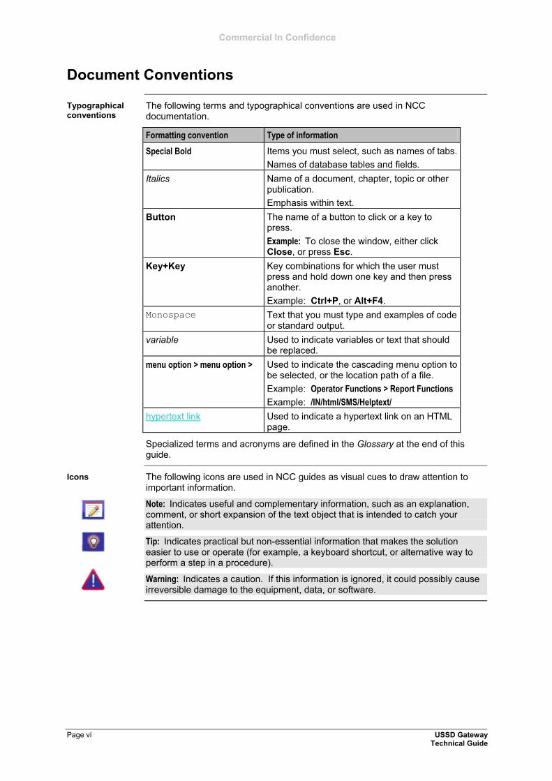
The following icons are used in NCC guides as visual cues to draw attention to important information.
Note: Indicates useful and complementary information, such as an explanation, comment, or short expansion of the text object that is intended to catch your attention.
Tip: Indicates practical but non-essential information that makes the solution easier to use or operate (for example, a keyboard shortcut, or alternative way to perform a step in a procedure).
Warning: Indicates a caution. If this information is ignored, it could possibly cause irreversible damage to the equipment, data, or software.
Typographical conventions
Icons
Commercial In Confidence
USSD Gateway Page 1 Technical Guide
System Overview
Overview
This chapter provides a high-level overview of the application. It explains the basic functionality of the system and lists the main components.
It is not intended to advise on any specific NCC network or service implications of the product.
This chapter contains the following topics.
What is USSD Gateway? ................................................................................ 2 Handset Interaction ......................................................................................... 5 Callback ........................................................................................................... 7 Alarms, Statistics, Reports and EDRs ............................................................. 9
Chapter 1
Introduction
In this chapter
Chapter 1 Commercial In Confidence
Page 2 USSD Gateway Technical Guide
What is USSD Gateway?
The USSD GW provides the following functions:
interaction using USSD messages between the subscriber's handset and the platform:
processing fast access, single string (typeahead) requests presenting information to mobile users using USSD messages complex interaction through navigation of menus based on user input
(interactive USSD)
IMSI Management:
different services can be configured for different IMSI prefixes barring by IMSI or IMSI prefix logging forbidden attempts to use the service, and tracing for all calls from an IMSI or IMSI prefix CDR Viewing screen provides full information about a call and provides
EDR searching
support for both USSD phase 1 / MAP1 and USSD phase 2 / MAP2, and
roaming USSD Session Control:
separate control plans for charging and call monitoring, and with Location Capabilities Pack, session can be initiated directly back to a
roaming subscriber.
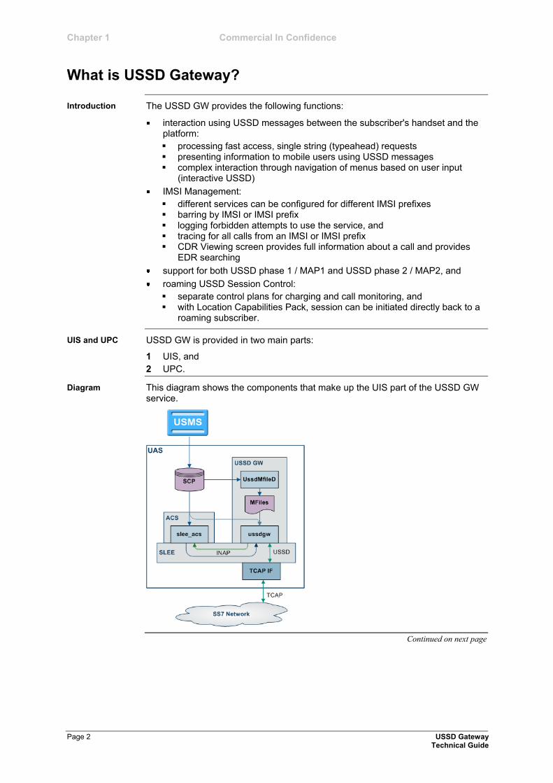
USSD GW is provided in two main parts:
1 UIS, and
2 UPC.
This diagram shows the components that make up the UIS part of the USSD GW service.
Continued on next page
Introduction
UIS and UPC
Diagram

Commercial In Confidence Chapter 1
What is USSD Gateway?, Continued
USSD Gateway Page 3 Technical Guide
This table describes the main components in USSD GW.
Process Role Further information
ussdgw The ussdgw process is the main USSD GW binary. It:
provides an interface between SLEE applications (including slee_acs) and the rest of the system, and
translates between INAP and USSD.
ussdgw (on page 44)
slee_acs The ACS process which runs control plans.
ACS Technical Guide
libupcService libupcService is the USSD GW service library plugin for slee_acs which handles initial set up of USSD call control plans.
libupcService (on page 46)
libupcChassisActions
libupcChassisActions provides the functions which enable the USSD GW Feature Nodes to interact with other elements in the system
libupcChassisActions (on page 47)
libupcMacroNodes This slee_acs plugin provides the USSD GW macro nodes.
libupcMacroNodes (on page 48)
The USSD Interactive Services Gateway (UIS) enables operators to provide interactive menu-based portal services to end users.
UIS translates between the network USSD messages received from handsets to the INAP messages used to communicate with ACS. UIS also determines the service that should handle in the incoming service initiation request.
UIS enables operators to provide a range of services using USSD messages from (and to) a subscriber's handset. Interaction is configured using ACS control plans. UIS can also process fast access, single-string requests to trigger platform functionality, including:
Subscriber account detail reports (with CCS)
Voucher recharges (with CCS), and
USSD Roaming call back.
USSD GW's USSD Portal Service (UPC) is an optional part of USSD GW that provides extended interactivity through the UPC Portal Screens and USSD GW feature nodes.
The UPC Portal Screens are used to extend the interactive USSD menus created using the UIS screens (for example by providing menu branching).
Continued on next page
Components
USSD Interactive Services Gateway
USSD Gateway Portal Service
Chapter 1 Commercial In Confidence
What is USSD Gateway?, Continued
Page 4 USSD Gateway Technical Guide
USSD GW uses the USSD protocol as defined by GSM phase 1 & 2. This means the majority of subscribers can use the menus without needing to upgrade their handsets.
This approach is an alternative delivery mechanism to WAP, as WAP support is still limited to middle- and higher-tier handsets.
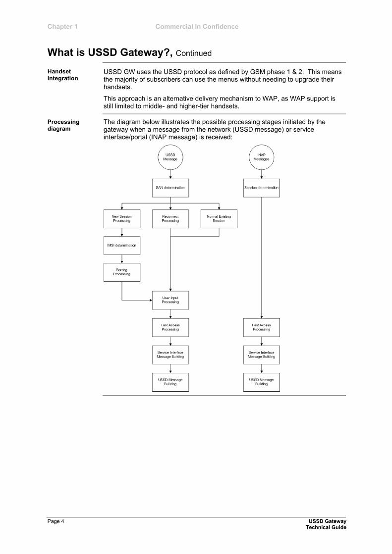
The diagram below illustrates the possible processing stages initiated by the gateway when a message from the network (USSD message) or service interface/portal (INAP message) is received:
Handset integration
Processing diagram

Commercial In Confidence Chapter 1
USSD Gateway Page 5 Technical Guide
Handset Interaction
There are two main methods for interacting with a handset:
1 USSD menus, and
2 Typeahead, single-string commands.
In both cases, the ussdgw (on page 44) process communicates back and forth with an ACS control plan. With USSD menus, the messages from the control plan are translated into USSD messages and are sent to the handset. The subscriber can then respond with another USSD message. For single string commands, ussdgw buffers the original request and responds to the messages from the control plan using each buffer in sequence.
USSD menus are created using the SMS screens. For more information about how to configure and use menus, see USSD GW User's Guide.
This diagram shows the call flow for a single-string handset interaction.
This table provides additional detail about the Example call flow diagram.
Flow Description
1 The HLR sends a USSD message to the SLC, where it is picked up by the TCAP interface (usually SIGTRAN stack).
2 The TCAP interface forwards the unchanged USSD message to ussdgw across the SLEE.
3 ussdgw parses the message, using:
* as the initial trigger prefix and to separate each field, and
# as a terminator.
ussdgw translates the USSD message into an INAP message, using the first field as the Service Number and forwards it to slee_acs across the SLEE.
Note: Service Number will not be used if a Replacement SAN is being used. For more information, see USSD GW User's Guide.
4 slee_acs loads the control plan for the Service Number based on standard criteria.
For more information about how slee_acs determines which control plan to load, see ACS Technical Guide.
Continued on next page
Introduction
Example call flow
Example call flow description
Chapter 1 Commercial In Confidence
Handset Interaction, Continued
Page 6 USSD Gateway Technical Guide
Example call flow description (continued)
Flow Description
5 The control plan executes until it reaches an interaction node. In this example, the node is a Selection Dependant Routing node which enables the subscriber to specify which service they want to use. An INAP PACUI message is created, specifying the uugw as the srf and the specifying the announcement id 1 from the node's configuration. This message is sent to ussdgw.
Warning: The srf configuration must specify uugw in the announcement and the uugw srf must also be configured in acs.conf or the message will not be received by ussdgw. For more information, see srf configuration (on page 16).
6 The ussdgw receives the PACUI and checks whether it has a buffer which contains unused data from the original USSD message. In this case it does, so it constructs an INAP CUI message using the 8 from the second field and sends it back to slee_acs.
7 slee_acs receives the CUI and continues the control plan as normal. In this case, the Selection Dependant Routing node routes the call to a Play Announcement node. A PA message is constructed and sent to ussdgw as described in stage 5.
8 ussdgw receives the PA message. In this case it has no unused buffers, so it uses the announcement id to determine what menu details to use in the USSD message it constructs and sends back to the HLR. In this case the message provides the information provided by the service selected in stage 6, and reports the date the account will expire.
Note: If the interaction node specifies a number of repetitions of 127, ussdgw will not construct a message to be sent to the subscriber.
9 ussdgw responds to the CUI with an SRR back to slee_acs which completes the control plan.
10 The subscriber receives the USSD message from the HLR.
Commercial In Confidence Chapter 1
USSD Gateway Page 7 Technical Guide
Callback
USSD GW can be used to enable USSD message-initiated call back. There are a number of ways this can be configured, but the main elements are:
1 subscriber initiates the call back using a USSD message
2 the system initiates the A leg of the call, then
3 the system completes the call by initiating the B leg.
The subscriber can initiate a callback using:
a single string which is parsed by the ussdgw process, or
an initial message followed by interaction defined in a control plan.
A-leg call initiation is done from a control plan using ACS's Call Initiation feature node. The Call Initiation node attempts to establish the A leg of the call by:
arming the switch to inform the platform when the A party answers the call (by sending an RRBCSM (oAnswer)), and
sending an Initiate Call Attempt (ICA) to the switch (the switch then sets up the call).
Note: The Call Initiation node can initiate a call with any destination number using any profile block or a hard coded value. The A leg is selected using the Call Initiation node's configuration. Because the A leg setup is done in a control plan, any function which is available in the control plan can be used, including:
checking subscriber's account state or balance, and
normalising the calling party number.
After Call Initiation node is called, initiating control plan continues when the A leg has answered and the IDP been sent. Further processing should continue in the new call generated by the IDP.
For more information about the Call Initiation feature node, see CPE User's Guide.
When the A party answers, the switch returns an ERBCSM (oAnswer) to the control plan and a new forked control plan starts. The new call can use any control plan functionality, including:
monitoring the new call, and
using a retrieved details (including MSRN) for charging.
The new forked call is responsible for connecting to the B leg (for example, by using an AT or a UATB node).
Continued on next page
Introduction
Callback initiation
A leg
B leg
Chapter 1 Commercial In Confidence
Callback, Continued
Page 8 USSD Gateway Technical Guide
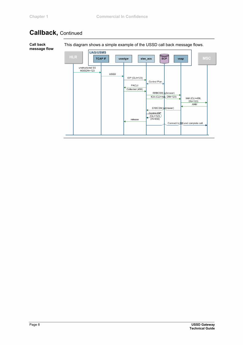
This diagram shows a simple example of the USSD call back message flows.
Call back message flow
Commercial In Confidence Chapter 1
USSD Gateway Page 9 Technical Guide
Alarms, Statistics, Reports and EDRs
USSD GW processes log alarms and notices to the syslog. They are then collected by the SMS alarms subsystem and moved to the SMS. For more information about alarms, see System Alarms.
SMS’s statistics subsystem collects and stores the statistics on the SMS as entries in the SMF database table SMF_STATISTICS. They can then be processed further by SMS or by third party systems.
This table lists the statistics collected about USSD GW.
Statistic Description
UIS_1 USSD session initiation attempt – phase 1
UIS_2 USSD session initiation attempt – phase 2.
UIS_3 Successful USSD initiation attempt (InitialDP sent to a service interface)
UIS_4 Message being sent to user as a result of a PACUI INAP operation from a service interface
UIS_5 User input as a result of an active PACUI
UIS_6 Fast access attempted on USSD session initiation (that is, dial ahead digits specified)
UIS_7 Timer Expiry (Session cut off)
UIS_8 Timer Expiry (SSF)
UIS_9 Timer Expiry (overall inactivity)
UIS_10 Timer Expiry (reconnect)
UIS_11 Timer Expiry (user inactivity)
UIS_12 TC-ABORT received from network
UIS_13 TC-ABORT received from service interface
UIS_14 Gateway call limiting
USSD GW can log Event Data Records for some transactions. Also, an EDR is logged for each call which passes through a control plan. For more information about the EDRs logged by USSD GW see <EDR_Rg_sn>.
Alarms
Statistics
EDRs

Commercial In Confidence
USSD Gateway Page 11 Technical Guide
Configuration
Overview
This chapter explains how to configure the application.
This chapter contains the following topics.
Configuration Overview ................................................................................. 12 Configuring the SLEE.cfg .............................................................................. 13 Configuring acs.conf for the SLC .................................................................. 15 Overview of the USSD Gateway Configuration ............................................ 17 Configuring the USSD Gateway Portal Component (UPC) .......................... 21 eserv.config Configuration............................................................................. 24 Response Date and Time.............................................................................. 26 EDR Section .................................................................................................. 34 Configuring the XML Interface and Enabling Tracing ................................... 39
Chapter 2
Introduction
In this chapter
Chapter 2 Commercial In Confidence
Page 12 USSD Gateway Technical Guide
Configuration Overview
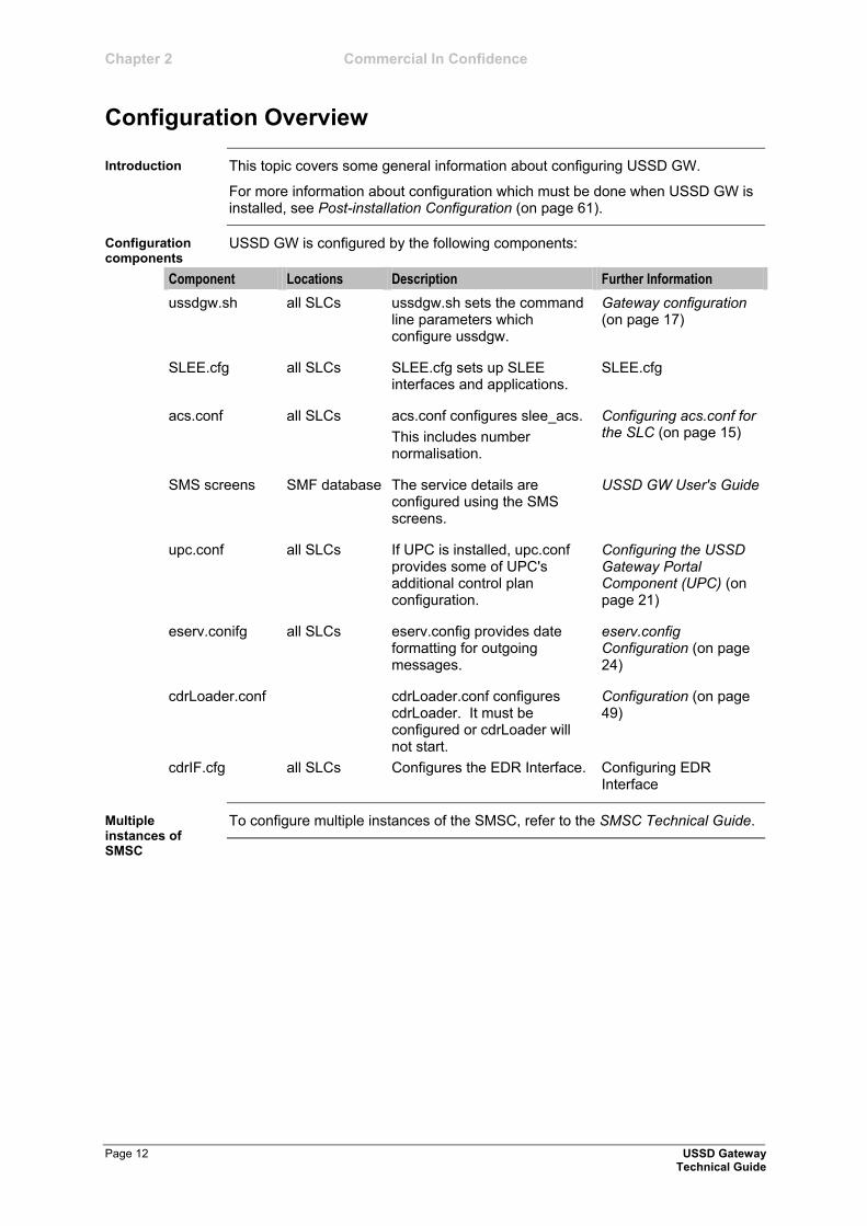
This topic covers some general information about configuring USSD GW.
For more information about configuration which must be done when USSD GW is installed, see Post-installation Configuration (on page 61).
USSD GW is configured by the following components:
Component Locations Description Further Information
ussdgw.sh all SLCs ussdgw.sh sets the command line parameters which configure ussdgw.
Gateway configuration (on page 17)
SLEE.cfg all SLCs SLEE.cfg sets up SLEE interfaces and applications.
SLEE.cfg
acs.conf all SLCs acs.conf configures slee_acs.
This includes number normalisation.
Configuring acs.conf for the SLC (on page 15)
SMS screens SMF database The service details are configured using the SMS screens.
USSD GW User's Guide
upc.conf all SLCs If UPC is installed, upc.conf provides some of UPC's additional control plan configuration.
Configuring the USSD Gateway Portal Component (UPC) (on page 21)
eserv.conifg all SLCs eserv.config provides date formatting for outgoing messages.
eserv.config Configuration (on page 24)
cdrLoader.conf cdrLoader.conf configures cdrLoader. It must be configured or cdrLoader will not start.
Configuration (on page 49)
cdrIF.cfg all SLCs Configures the EDR Interface. Configuring EDR Interface
To configure multiple instances of the SMSC, refer to the SMSC Technical Guide.
Introduction
Configuration components
Multiple instances of SMSC
Commercial In Confidence Chapter 2
USSD Gateway Page 13 Technical Guide
Configuring the SLEE.cfg
The system is configured so that USSD Gateway and associated interfaces all start together. This is performed using the /IN/service_packages/SLEE/etc/SLEE.cfg file.
Note: The directory /IN/service_packages/SLEE and all its subdirectories/files should be owned by the user acs_oper.
This can be done using: chown –R acs_oper:IN SLEE in the directory
/IN/service_packages.
The SLEE.cfg file will be automatically edited to add the USSD Gateway components and interface entries.
The SLEE.cfg configuration file is automatically updated. To check:
Step Action
1 cd to the following directory:
/IN/service_packages/SLEE/bin
2 An example slee.sh file: #!/bin/sh
LD_LIBRARY_PATH=$LD_LIBRARY_PATH:/IN/service_packages/SLEE/
lib
export LD_LIBRARY_PATH
SHLIB_PATH=$SHLIB_PATH:/IN/service_packages/SLEE/lib
export SHLIB_PATH
/IN/service_packages/SLEE/bin/sleeStartup
/IN/service_packages/SLEE/etc/SLEE.cfg
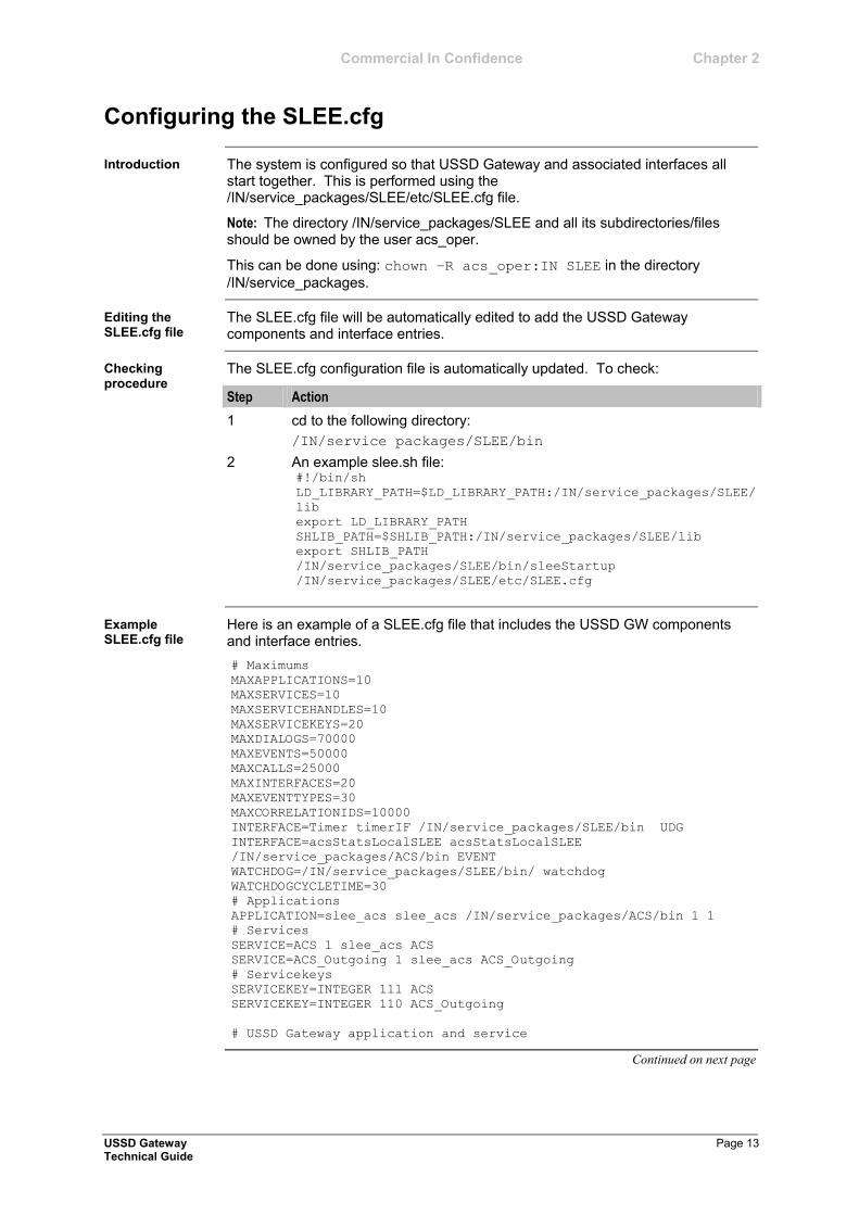
Here is an example of a SLEE.cfg file that includes the USSD GW components and interface entries.
# Maximums
MAXAPPLICATIONS=10
MAXSERVICES=10
MAXSERVICEHANDLES=10
MAXSERVICEKEYS=20
MAXDIALOGS=70000
MAXEVENTS=50000
MAXCALLS=25000
MAXINTERFACES=20
MAXEVENTTYPES=30
MAXCORRELATIONIDS=10000
INTERFACE=Timer timerIF /IN/service_packages/SLEE/bin UDG
INTERFACE=acsStatsLocalSLEE acsStatsLocalSLEE
/IN/service_packages/ACS/bin EVENT
WATCHDOG=/IN/service_packages/SLEE/bin/ watchdog
WATCHDOGCYCLETIME=30
# Applications
APPLICATION=slee_acs slee_acs /IN/service_packages/ACS/bin 1 1
# Services
SERVICE=ACS 1 slee_acs ACS
SERVICE=ACS_Outgoing 1 slee_acs ACS_Outgoing
# Servicekeys
SERVICEKEY=INTEGER 111 ACS
SERVICEKEY=INTEGER 110 ACS_Outgoing
# USSD Gateway application and service
Continued on next page
Introduction
Editing the SLEE.cfg file
Checking procedure
Example SLEE.cfg file
Chapter 2 Commercial In Confidence
Configuring the SLEE.cfg, Continued
Page 14 USSD Gateway Technical Guide
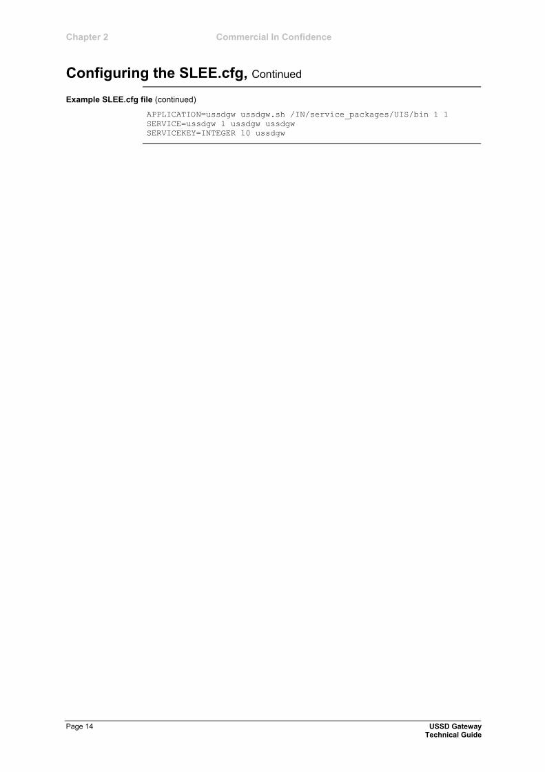
Example SLEE.cfg file (continued)
APPLICATION=ussdgw ussdgw.sh /IN/service_packages/UIS/bin 1 1
SERVICE=ussdgw 1 ussdgw ussdgw
SERVICEKEY=INTEGER 10 ussdgw

Commercial In Confidence Chapter 2
USSD Gateway Page 15 Technical Guide
Configuring acs.conf for the SLC
USSD GW provides functionality which is used by the main call processing subsystem, slee_acs. slee_acs is the main binary in ACS and is configured by acs.conf.
For slee_acs to support USSD GW functionality, some configuration must be added to acs.conf.
The following pages contain a description of each section that must be changed and the acs.conf parameters that appear within that section which are relevant to USSD GW.
The USSD gateway can be configured to send '*' and '#' to the portal. However, the '*' and '#' is sent across the network as hex digits 'C' and 'D' respectively.
This means if ACS is used as the portal, it will need to be configured to recognise incoming hex digit 'C' as '*' and 'D' as '#'. This is achieved by adding/changing the following configuration parameters in the acsChassis section:
DialledStarEncoding C
DialledHashEncoding D
Note: The default installation of ACS has the following:
DialledStarEncoding B
DialledHashEncoding C
Before starting this section you must understand the layout of the ACS configuration file, acs.conf. For more details of the layout of acs.conf, refer to the ACS Technical Guide.
Follow these steps to ensure that ACS recognises hex digit 'C' as '*' and 'D' as '#'.
Step Action
1 Log in to the SLC as acs_oper.
2 As acs_oper, edit acs.conf:
Example command: vi /IN/service_packages/ACS/etc/acs.conf
3 Set these parameters to the following: DialledStarEncoding C
DialledHashEncoding D
Notes:
There must be a single space before the beginning of each parameter.
If the parameters are not found, then add them to acs.conf under the acsChassis section.
4 Restart the SLEE.
For more information about restarting the SLEE, see SLEE Technical Guide.
If the UPC part of USSD GW is being used, acs.conf must include the plugin libraries supplied by the upcScp package. A default configuration is added on installation for the following libraries:
Continued on next page
Introduction
Configuring ACS to recognise hex digits
Checking encoding parameters
UPC library configuration
Chapter 2 Commercial In Confidence
Configuring acs.conf for the SLC, Continued
Page 16 USSD Gateway Technical Guide
UPC library configuration (continued)
libupcService (on page 46)
libupcChassisActions (on page 47), and
libupcMacroNodes (on page 48).
For more information about the acs.conf entries for these libraries, see the Startup section for each binary.
The Send Buffer node is a feature node that allows ACS to send the content of a pre-defined buffer in the form of a short message to an end-user during at runtime. It is possible to configure the origination address and destination address of the short message to normalised calling and called party numbers.
In order to use normalised calling and called party numbers either originating or destination address, normalisation needs to be configured in ACS. Whilst this is not configuration of the Send Buffer node, it is required and hence listed below.
Note: The calling party number is the MSISDN of the calling mobile. It is important to know the format of the MSISDN that the network passes to the USSD GW before attempting to configure ACS number normalisation. For more information about ACS number normalisation configuration rules, see the ACS Technical Guide.
Control plans use Interaction nodes to send INAP messages to ussdgw as if ussdgw was a VIP or media server. In order to do this, ACS must include some specific configuration in order to work with USSD GW.
1 The interaction nodes must use announcements which have been set up to point at ussdgw instead of a normal media server. This is done by specifying announcements which use the srf of "uugw" by specifying uugw as their Resource Name in the New/Edit Announcement screen.
2 acs.conf then includes the uugw srf ids to match the announcement srfs.
Example: srf (uugw,tcapPreEnd=Y,UseETC=N,Address=,NOA=4)
Send Buffer Node - number normalisation
srf configuration
Commercial In Confidence Chapter 2
USSD Gateway Page 17 Technical Guide
Overview of the USSD Gateway Configuration
Exclusive configuration for the USSD Gateway is contained in the ussdgw.sh file in /IN/service_packages/UIS/bin.
This file is created automatically from the install script.
ussdgw supports these command line parameters.
Note: ussdgw is usually started by the shell script ussdgw.sh. ussdgw's configuration is usually set in the shell script. For more information about ussdgw.sh, see Startup (on page 44).
-l <usr>/<pwd>
Syntax: -l <usr>/<pwd>
Description: The Oracle username and password for logging into the SCP database.
Type: String
Optionality: Optional (default used if not set).
Default: /
-n <name>
Syntax: -n <name>
Description: Global Gateway Name.
Type: String
Optionality: Optional (default used if not set).
Default: Global GW config
-c <if>
Syntax: -c <if>
Description: The SLEE CDR Interface Name.
Type: String
Optionality: Optional (default used if not set).
Default: Cdr
-s <opt>
Syntax: -s <opt>
Description: When present, for MAP2 messages the MSISDN is populated from the msisdnreference field.
Type: String
Allowed: msisdnref
Example: -s msisdnref
Continued on next page
Introduction
Gateway configuration
Chapter 2 Commercial In Confidence
Overview of the USSD Gateway Configuration, Continued
Page 18 USSD Gateway Technical Guide
Gateway configuration (continued)
-o <opt>
Syntax: -o <opt>
Description: How to populate the MSISDN in the IDP.
Type: String
Allowed: imsi Use IMSI from incoming Map1BeginSubscriberActivity for the MSISDN in the IDP.
oen Use OriginatingEntityNumber from incoming Map1BeginSubscriberActivity for the MSISDN in the IDP.
none Do not populate the MSISDN in the IDP.
-e <opt>
Syntax: -e <opt>
Description: How to populate the IMSI.
Type: String
Allowed: imsi Use IMSI from incoming Map1BeginSubscriberActivity for the IMSI.
oen Use OriginatingEntityNumber from incoming Map1BeginSubscriberActivity for the IMSI.
none Do not populate the IMSI.
-v <id>
Syntax: -v <id>
Description: The VLR announcement set id.
Type: Integer
Optionality: Optional (default used if not set).
Default: - (disabled by default)
-m <max>
Syntax: -m <max>
Description: The maximum number of concurrent calls allowed.
Type: Integer
Optionality: Optional (default used if not set).
Default: - (unlimited by default)
Continued on next page
Commercial In Confidence Chapter 2
Overview of the USSD Gateway Configuration, Continued
USSD Gateway Page 19 Technical Guide
Gateway configuration (continued)
-r <opt>
Syntax: -r <opt>
Description: Append received PA messages to a buffer and send the contents of the buffer in the final release message.
Type: String
Allowed: send_PA_on_Rel
send_PA_on_Rel_MAP
send_PA_on_Rel_MAP2
-a
Syntax: -a
Description: When present, the Release message is appended.
Type: Boolean
Optionality: Optional (default used if not set).
Default: Not present (unset).
-p
Syntax: -p
Description: Send SpecializedResourceReport in response to PA or PACUI timeout.
Type: Boolean
Optionality: Optional (default used if not set).
Default: - (disabled by default)
-u
Syntax: -u
Description: Send Unicode Characters.
Type: Boolean
Optionality: Optional (default used if not set).
Default: - (disabled by default)
Warning: Your db character set must be UTF8 to send Unicode.
-z <str>
Syntax: -z <str>
Description: The string to change "+"s in a number from the handset to.
Type: String of zero or more digits
Optionality: Optional (no replacements are made if not set).
Default: None
Example: -z 00
This rule would change an incoming number of +641234567890 to 00641234567890.
Continued on next page
Chapter 2 Commercial In Confidence
Overview of the USSD Gateway Configuration, Continued
Page 20 USSD Gateway Technical Guide
Gateway configuration (continued)
-w
Syntax: -w
Description: Strips leading and trailing white space from the typeahead text returned in PACUI responses.
Optionality: Optional (no white space removal actions).
Default: None
Notes: This rule would change incoming typeahead text of:
*103*1239*1239 # to
*103*1239*1239#
Example: -w
Here is the startup script code.
#!/bin/sh
cd /IN/service_packages/UIS/bin
exec ./ussdgw --oracle-login / --cdr-interface cdrIF
ussdgw.sh code
Commercial In Confidence Chapter 2
USSD Gateway Page 21 Technical Guide
Configuring the USSD Gateway Portal Component (UPC)
UPC can be conceptually divided into two main components:
Component that resides in ACS, which is started and controlled by ACS.
Component that is controlled by the SLEE directly.
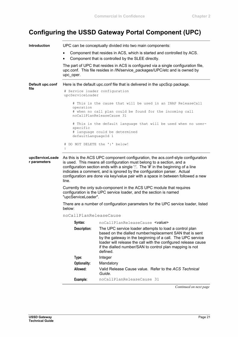
The part of UPC that resides in ACS is configured via a single configuration file, upc.conf. This file resides in /IN/service_packages/UPC/etc and is owned by upc_oper.
Here is the default upc.conf file that is delivered in the upcScp package.
# Service loader configuration
upcServiceLoader
# This is the cause that will be used in an INAP ReleaseCall
operation
# when no call plan could be found for the incoming call
noCallPlanReleaseCause 31
# This is the default language that will be used when no user-
specific
# language could be determined
defaultLanguageId 1
# DO NOT DELETE the ':' below!
:
As this is the ACS UPC component configuration, the acs.conf-style configuration is used. This means all configuration must belong to a section, and a configuration section ends with a single ':'. The '#' in the beginning of a line indicates a comment, and is ignored by the configuration parser. Actual configuration are done via key/value pair with a space in between followed a new line.
Currently the only sub-component in the ACS UPC module that requires configuration is the UPC service loader, and the section is named "upcServiceLoader".
There are a number of configuration parameters for the UPC service loader, listed below:
noCallPlanReleaseCause
Syntax: noCallPlanReleaseCause <value>
Description: The UPC service loader attempts to load a control plan based on the dialled number/replacement SAN that is sent by the gateway in the beginning of a call. The UPC service loader will release the call with the configured release cause if the dialled number/SAN to control plan mapping is not defined.
Type: Integer
Optionality: Mandatory
Allowed: Valid Release Cause value. Refer to the ACS Technical Guide.
Example: noCallPlanReleaseCause 31
Continued on next page
Introduction
Default upc.conf file
upcServiceLoader parameters
Chapter 2 Commercial In Confidence
Configuring the USSD Gateway Portal Component (UPC), Continued
Page 22 USSD Gateway Technical Guide
upcServiceLoader parameters (continued)
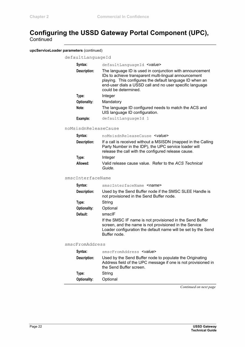
defaultLanguageId
Syntax: defaultLanguageId <value>
Description: The language ID is used in conjunction with announcement IDs to achieve transparent multi-lingual announcement playing. This configures the default language ID when an end-user dials a USSD call and no user specific language could be determined.
Type: Integer
Optionality: Mandatory
Note: The language ID configured needs to match the ACS and UIS language ID configuration.
Example: defaultLanguageId 1
noMsisdnReleaseCause
Syntax: noMsisdnReleaseCause <value>
Description: If a call is received without a MSISDN (mapped in the Calling Party Number in the IDP), the UPC service loader will release the call with the configured release cause.
Type: Integer
Allowed: Valid release cause value. Refer to the ACS Technical Guide.
smscInterfaceName
Syntax: smscInterfaceName <name>
Description: Used by the Send Buffer node if the SMSC SLEE Handle is not provisioned in the Send Buffer node.
Type: String
Optionality: Optional
Default: smscIF
If the SMSC IF name is not provisioned in the Send Buffer screen, and the name is not provisioned in the Service Loader configuration the default name will be set by the Send Buffer node.
smscFromAddress
Syntax: smscFromAddress <value>
Description: Used by the Send Buffer node to populate the Originating Address field of the UPC message if one is not provisioned in the Send Buffer screen.
Type: String
Optionality: Optional
Continued on next page

Commercial In Confidence Chapter 2
Configuring the USSD Gateway Portal Component (UPC), Continued
USSD Gateway Page 23 Technical Guide
Follow these steps to modify upc.conf to disconnect calls with no MSISDN (such as MAP 1 calls). This is optional.
Step Action
1 Log in as upc_oper # su - upc_oper
2 Edit upc.conf: $ vi /IN/service_packages/UPC/etc
/upc.conf
3 Add noMsisdnReleaseCause <value> within the upcServiceLoader
(on page 21) section. Note that indentation may be added for human-readibility.
4 Restart the SLEE.
5 If a call release cause has been configured in the UPC.conf (that is - noCallPlanReleaseCause or noMsisdnReleaseCause), the following will also need to be configured, enabling the correct text message to be sent back to the user.
The Status Info tab allows you to map status values to move meaningful status messages.
Using the SMS screen select Service>USSD Gateway>Menu & Status>Config and select the Status Info tab. Add a new name and add a value that is equal to the number used for the release cause in the upc.conf file.
For further details refer to the USSD Gateway User Guide.
6 The Status Language tab allows you to set language specific status text for a given status.
Select Service>USSD Gateway>Menu & Status>Display and select the Status Language tab. Select the menu just created and add the text required to be displayed to the user.
Release calls with no MSISDN instructions
Chapter 2 Commercial In Confidence
Page 24 USSD Gateway Technical Guide
eserv.config Configuration
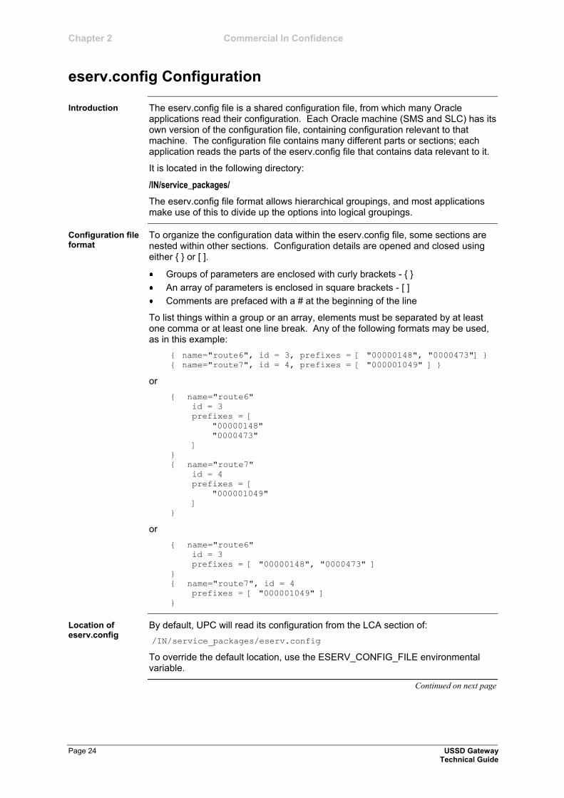
The eserv.config file is a shared configuration file, from which many Oracle applications read their configuration. Each Oracle machine (SMS and SLC) has its own version of the configuration file, containing configuration relevant to that machine. The configuration file contains many different parts or sections; each application reads the parts of the eserv.config file that contains data relevant to it.
It is located in the following directory:
/IN/service_packages/
The eserv.config file format allows hierarchical groupings, and most applications make use of this to divide up the options into logical groupings.
To organize the configuration data within the eserv.config file, some sections are nested within other sections. Configuration details are opened and closed using either { } or [ ].
Groups of parameters are enclosed with curly brackets - { }
An array of parameters is enclosed in square brackets - [ ]
Comments are prefaced with a # at the beginning of the line
To list things within a group or an array, elements must be separated by at least one comma or at least one line break. Any of the following formats may be used, as in this example:
{ name="route6", id = 3, prefixes = [ "00000148", "0000473"] }
{ name="route7", id = 4, prefixes = [ "000001049" ] }
or
{ name="route6"
id = 3
prefixes = [
"00000148"
"0000473"
]
}
{ name="route7"
id = 4
prefixes = [
"000001049"
]
}
or
{ name="route6"
id = 3
prefixes = [ "00000148", "0000473" ]
}
{ name="route7", id = 4
prefixes = [ "000001049" ]
}
By default, UPC will read its configuration from the LCA section of:
/IN/service_packages/eserv.config
To override the default location, use the ESERV_CONFIG_FILE environmental variable.
Continued on next page
Introduction
Configuration file format
Location of eserv.config
Commercial In Confidence Chapter 2
eserv.config Configuration, Continued
USSD Gateway Page 25 Technical Guide
Location of eserv.config (continued)
ESERV_CONFIG_FILE
Syntax: ESERV_CONFIG_FILE = "<path>/<file>"
Description: The directory eserv.config configuration file will be read from.
Type: String
Optionality: Optional (default used if not set).
Default: /IN/service_packages/eserv.config
Open the configuration file on your system using a standard text editor. Do not use text editors such as MS Word, that attach control characters. These can be, for example, Microsoft DOS or Windows line termination characters (for example: ^M), which are not visible to the user, at the end of each row. This will cause file errors when the application tries to read the configuration file.
Always keep a backup of your file before making any changes to it. This will ensure you have a working copy which you can return to if necessary.
Most applications come with an example eserv.config configuration in a file called eserv.config.example in the root of the application directory.
Warning: This file is not intended to be changed by the user. Please contact the Oracle support with your queries.
Editing the file
eserv.config files delivered
Chapter 2 Commercial In Confidence
Page 26 USSD Gateway Technical Guide
Response Date and Time
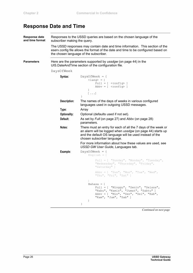
Responses to the USSD queries are based on the chosen language of the subscriber making the query.
The USSD responses may contain date and time information. This section of the eserv.config file allows the format of the date and time to be configured based on the chosen language of the subscriber.
Here are the parameters supported by ussdgw (on page 44) in the UIS.DateAndTime section of the configuration file.
DaysOfWeek
Syntax: DaysOfWeek = { <lang> = {
Full = [ <config> ]
Abbv = [ <config> ]
}
[...]
}
Description: The names of the days of weeks in various configured languages used in outgoing USSD messages.
Type: Array
Optionality: Optional (defaults used if not set).
Default: As set by Full (on page 27) and Abbv (on page 28) parameters.
Notes: There must an entry for each of all the 7 days of the week or an alarm will be logged when ussdgw (on page 44) starts up and the default OS language will be used instead of the chosen subscriber language.
For more information about how these values are used, see USSD GW User Guide, Languages tab.
Example: DaysOfWeek = { English = {
Full = [ "Sunday", "Monday", "Tuesday",
"Wednesday", "Thursday", "Friday",
"Saturday" ]
Abbv = [ "Sun", "Mon", "Tue", "Wed",
"Thu", "Fri", "Sat" ]
}
Bahasa = {
Full = [ "Minggu", "Senin", "Selasa",
"Rabu", "Kamis", "Jumat", "Sabtu" ]
Abbv = [ "Min", "Sen", "Sel", "Rab",
"Kam", "Jum", "Sab" ]
}
}
Continued on next page
Response date and time format
Parameters
Commercial In Confidence Chapter 2
Response Date and Time, Continued
USSD Gateway Page 27 Technical Guide
Parameters (continued)
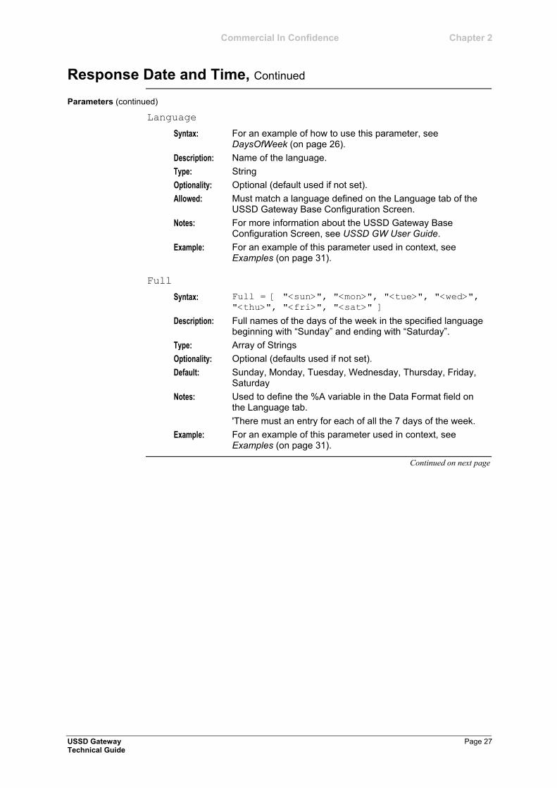
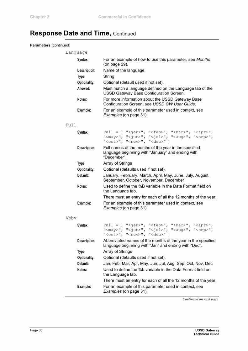
Language
Syntax: For an example of how to use this parameter, see DaysOfWeek (on page 26).
Description: Name of the language.
Type: String
Optionality: Optional (default used if not set).
Allowed: Must match a language defined on the Language tab of the USSD Gateway Base Configuration Screen.
Notes: For more information about the USSD Gateway Base Configuration Screen, see USSD GW User Guide.
Example: For an example of this parameter used in context, see Examples (on page 31).
Full
Syntax: Full = [ "<sun>", "<mon>", "<tue>", "<wed>",
"<thu>", "<fri>", "<sat>" ]
Description: Full names of the days of the week in the specified language beginning with ―Sunday‖ and ending with ―Saturday‖.
Type: Array of Strings
Optionality: Optional (defaults used if not set).
Default: Sunday, Monday, Tuesday, Wednesday, Thursday, Friday, Saturday
Notes: Used to define the %A variable in the Data Format field on the Language tab.
'There must an entry for each of all the 7 days of the week.
Example: For an example of this parameter used in context, see Examples (on page 31).
Continued on next page
Chapter 2 Commercial In Confidence
Response Date and Time, Continued
Page 28 USSD Gateway Technical Guide
Parameters (continued)
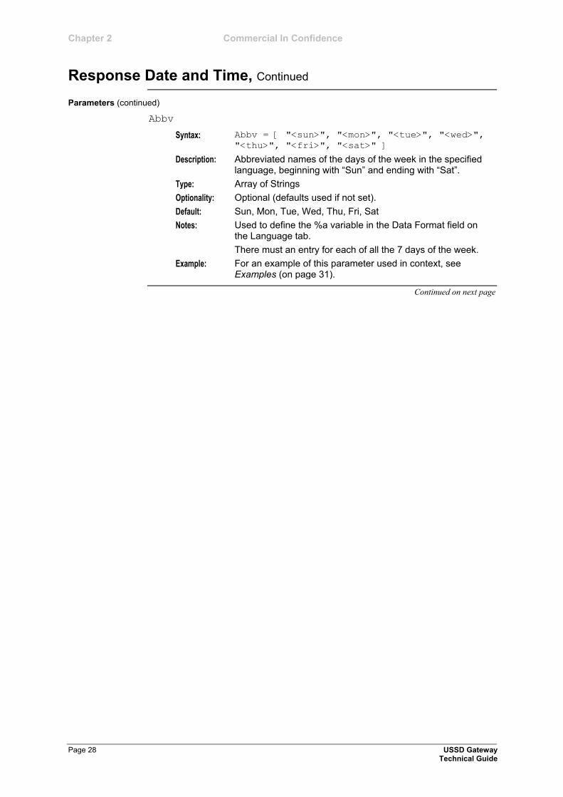
Abbv
Syntax: Abbv = [ "<sun>", "<mon>", "<tue>", "<wed>",
"<thu>", "<fri>", "<sat>" ]
Description: Abbreviated names of the days of the week in the specified language, beginning with ―Sun‖ and ending with ―Sat‖.
Type: Array of Strings
Optionality: Optional (defaults used if not set).
Default: Sun, Mon, Tue, Wed, Thu, Fri, Sat
Notes: Used to define the %a variable in the Data Format field on the Language tab.
There must an entry for each of all the 7 days of the week.
Example: For an example of this parameter used in context, see Examples (on page 31).
Continued on next page
Commercial In Confidence Chapter 2
Response Date and Time, Continued
USSD Gateway Page 29 Technical Guide
Parameters (continued)
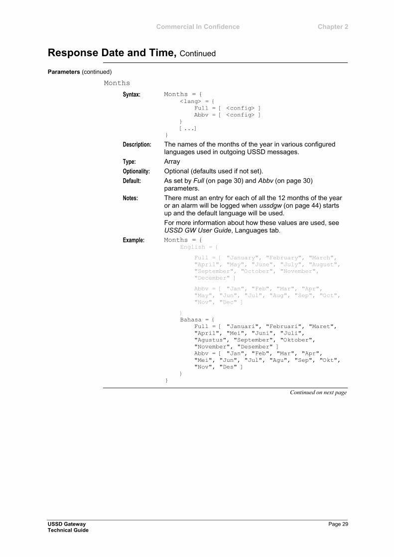
Months
Syntax: Months = { <lang> = {
Full = [ <config> ]
Abbv = [ <config> ]
}
[...]
}
Description: The names of the months of the year in various configured languages used in outgoing USSD messages.
Type: Array
Optionality: Optional (defaults used if not set).
Default: As set by Full (on page 30) and Abbv (on page 30) parameters.
Notes: There must an entry for each of all the 12 months of the year or an alarm will be logged when ussdgw (on page 44) starts up and the default language will be used.
For more information about how these values are used, see USSD GW User Guide, Languages tab.
Example: Months = { English = {
Full = [ "January", "February", "March",
"April", "May", "June", "July", "August",
"September", "October", "November",
"December" ]
Abbv = [ "Jan", "Feb", "Mar", "Apr",
"May", "Jun", "Jul", "Aug", "Sep", "Oct",
"Nov", "Dec" ]
}
Bahasa = {
Full = [ "Januari", "Februari", "Maret",
"April", "Mei", "Juni", "Juli",
"Agustus", "September", "Oktober",
"November", "Desember" ]
Abbv = [ "Jan", "Feb", "Mar", "Apr",
"Mei", "Jun", "Jul", "Agu", "Sep", "Okt",
"Nov", "Des" ]
}
}
Continued on next page
Chapter 2 Commercial In Confidence
Response Date and Time, Continued
Page 30 USSD Gateway Technical Guide
Parameters (continued)
Language
Syntax: For an example of how to use this parameter, see Months (on page 29).
Description: Name of the language.
Type: String
Optionality: Optional (default used if not set).
Allowed: Must match a language defined on the Language tab of the USSD Gateway Base Configuration Screen.
Notes: For more information about the USSD Gateway Base Configuration Screen, see USSD GW User Guide.
Example: For an example of this parameter used in context, see Examples (on page 31).
Full
Syntax: Full = [ "<jan>", "<feb>", "<mar>", "<apr>",
"<may>", "<jun>", "<jul>", "<aug>", "<sep>",
"<oct>", "<nov>", "<dec>" ]
Description: Full names of the months of the year in the specified language beginning with ―January‖ and ending with ―December‖.
Type: Array of Strings
Optionality: Optional (defaults used if not set).
Default: January, February, March, April, May, June, July, August, September, October, November, December
Notes: Used to define the %B variable in the Data Format field on the Language tab.
There must an entry for each of all the 12 months of the year.
Example: For an example of this parameter used in context, see Examples (on page 31).
Abbv
Syntax: Full = [ "<jan>", "<feb>", "<mar>", "<apr>",
"<may>", "<jun>", "<jul>", "<aug>", "<sep>",
"<oct>", "<nov>", "<dec>" ]
Description: Abbreviated names of the months of the year in the specified language beginning with ―Jan‖ and ending with ―Dec‖.
Type: Array of Strings
Optionality: Optional (defaults used if not set).
Default: Jan, Feb, Mar, Apr, May, Jun, Jul, Aug, Sep, Oct, Nov, Dec
Notes: Used to define the %b variable in the Data Format field on the Language tab.
There must an entry for each of all the 12 months of the year.
Example: For an example of this parameter used in context, see Examples (on page 31).
Continued on next page

Commercial In Confidence Chapter 2
Response Date and Time, Continued
USSD Gateway Page 31 Technical Guide
Example 1
This text shows an example of 1 Language:
Primary Language = Bahasa
Other Languages = None
DateAndTime = {
DaysOfWeek = {
Bahasa = {
Full = [ "Minggu", "Senin", "Selasa", "Rabu",
"Kamis", "Jumat", "Sabtu" ]
Abbv = [ "Min", "Sen", "Sel", "Rab", "Kam", "Jum",
"Sab" ]
}
}
Months = {
Bahasa = {
Full = [ "Januari", "Februari", "Maret", "April",
"Mei", "Juni", "Juli", "Agustus",
"September", "Oktober", "November", "Desember"
]
Abbv = [ "Jan", "Feb", "Mar", "Apr", "Mei", "Jun",
"Jul", "Agu", "Sep", "Okt", "Nov", "Des" ]
}
}
}
Continued on next page
Examples
Chapter 2 Commercial In Confidence
Response Date and Time, Continued
Page 32 USSD Gateway Technical Guide
Examples (continued)
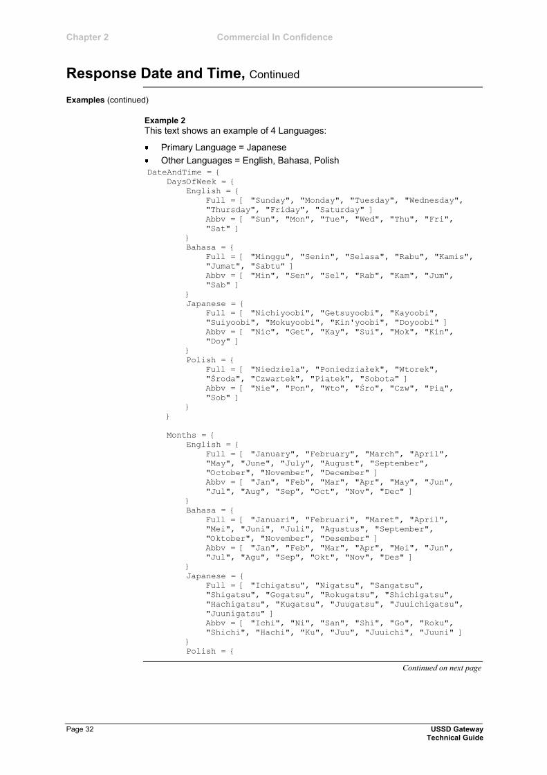
Example 2
This text shows an example of 4 Languages:
Primary Language = Japanese
Other Languages = English, Bahasa, Polish
DateAndTime = {
DaysOfWeek = {
English = {
Full = [ "Sunday", "Monday", "Tuesday", "Wednesday",
"Thursday", "Friday", "Saturday" ]
Abbv = [ "Sun", "Mon", "Tue", "Wed", "Thu", "Fri",
"Sat" ]
}
Bahasa = {
Full = [ "Minggu", "Senin", "Selasa", "Rabu", "Kamis",
"Jumat", "Sabtu" ]
Abbv = [ "Min", "Sen", "Sel", "Rab", "Kam", "Jum",
"Sab" ]
}
Japanese = {
Full = [ "Nichiyoobi", "Getsuyoobi", "Kayoobi",
"Suiyoobi", "Mokuyoobi", "Kin'yoobi", "Doyoobi" ]
Abbv = [ "Nic", "Get", "Kay", "Sui", "Mok", "Kin",
"Doy" ]
}
Polish = {
Full = [ "Niedziela", "Poniedziałek", "Wtorek",
"Środa", "Czwartek", "Piątek", "Sobota" ]
Abbv = [ "Nie", "Pon", "Wto", "Śro", "Czw", "Pią",
"Sob" ]
}
}
Months = {
English = {
Full = [ "January", "February", "March", "April",
"May", "June", "July", "August", "September",
"October", "November", "December" ]
Abbv = [ "Jan", "Feb", "Mar", "Apr", "May", "Jun",
"Jul", "Aug", "Sep", "Oct", "Nov", "Dec" ]
}
Bahasa = {
Full = [ "Januari", "Februari", "Maret", "April",
"Mei", "Juni", "Juli", "Agustus", "September",
"Oktober", "November", "Desember" ]
Abbv = [ "Jan", "Feb", "Mar", "Apr", "Mei", "Jun",
"Jul", "Agu", "Sep", "Okt", "Nov", "Des" ]
}
Japanese = {
Full = [ "Ichigatsu", "Nigatsu", "Sangatsu",
"Shigatsu", "Gogatsu", "Rokugatsu", "Shichigatsu",
"Hachigatsu", "Kugatsu", "Juugatsu", "Juuichigatsu",
"Juunigatsu" ]
Abbv = [ "Ichi", "Ni", "San", "Shi", "Go", "Roku",
"Shichi", "Hachi", "Ku", "Juu", "Juuichi", "Juuni" ]
}
Polish = {
Continued on next page
Commercial In Confidence Chapter 2
Response Date and Time, Continued
USSD Gateway Page 33 Technical Guide
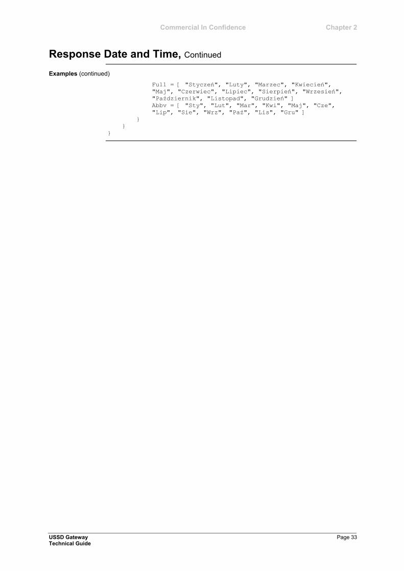
Examples (continued)
Full = [ "Styczeń", "Luty", "Marzec", "Kwiecień",
"Maj", "Czerwiec", "Lipiec", "Sierpień", "Wrzesień",
"Październik", "Listopad", "Grudzień" ]
Abbv = [ "Sty", "Lut", "Mar", "Kwi", "Maj", "Cze",
"Lip", "Sie", "Wrz", "Paź", "Lis", "Gru" ]
}
}
}
Chapter 2 Commercial In Confidence
Page 34 USSD Gateway Technical Guide
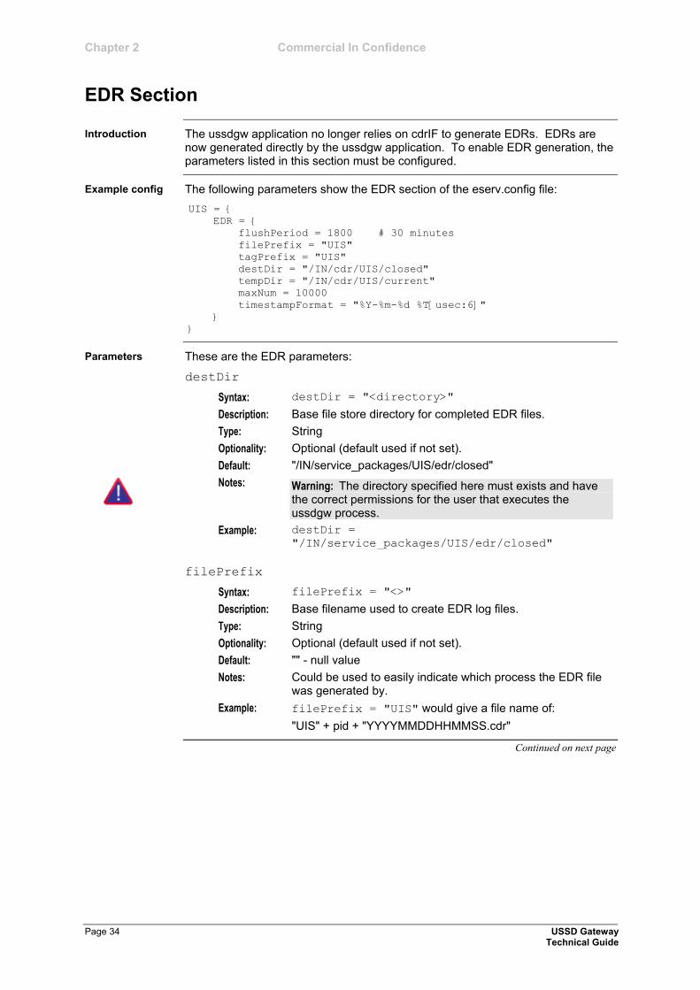
EDR Section
The ussdgw application no longer relies on cdrIF to generate EDRs. EDRs are now generated directly by the ussdgw application. To enable EDR generation, the parameters listed in this section must be configured.
The following parameters show the EDR section of the eserv.config file:
UIS = {
EDR = {
flushPeriod = 1800 # 30 minutes
filePrefix = "UIS"
tagPrefix = "UIS"
destDir = "/IN/cdr/UIS/closed"
tempDir = "/IN/cdr/UIS/current"
maxNum = 10000
timestampFormat = "%Y-%m-%d %T[usec:6]"
}
}
These are the EDR parameters:
destDir
Syntax: destDir = "<directory>"
Description: Base file store directory for completed EDR files.
Type: String
Optionality: Optional (default used if not set).
Default: "/IN/service_packages/UIS/edr/closed"
Notes: Warning: The directory specified here must exists and have the correct permissions for the user that executes the ussdgw process.
Example: destDir =
"/IN/service_packages/UIS/edr/closed"
filePrefix
Syntax: filePrefix = "<>"
Description: Base filename used to create EDR log files.
Type: String
Optionality: Optional (default used if not set).
Default: "" - null value
Notes: Could be used to easily indicate which process the EDR file was generated by.
Example: filePrefix = "UIS" would give a file name of:
"UIS" + pid + "YYYYMMDDHHMMSS.cdr"
Continued on next page
Introduction
Example config
Parameters
Commercial In Confidence Chapter 2
EDR Section, Continued
USSD Gateway Page 35 Technical Guide
Parameters (continued)
flushPeriod
Syntax: flushPeriod = <seconds>
Description: How long (in seconds) before closing the current EDR file and moving to the Destination EDR Directory (ref. destDir).
Type: Integer
Optionality: Optional (default used if not set).
Allowed: Any positive integer.
Default: 0 - A value of zero indicates that no EDR files will be generated.
Notes: A recommended value for flushPeriod would be 600 (10 minutes) or larger. Setting this value too small (e.g. less than 2 or 3 minutes) may not be optimum with respect to system performance as this would cause EDR files to be generated too often.
Used in conjunction with the maxNum parameter, a value of say 1800 would allow EDR files to be generated every 30 minutes or earlier if the number of EDRs in the current file exceeds the maxNum value.
Warning: If flushPeriod is not set (or set to 0), no EDR files will be generated even if the Cdr Flag check boxes on the SMS Screens are ticked.
Example: flushPeriod = 1800
maxNum
Syntax: maxNum = <value>
Description: Max number of EDRs per file.
Type: Integer
Optionality: Optional (default used if not set).
Allowed: Any positive integer.
Default: 10000
Notes: Used in conjunction with the flushPeriod parameter.
Example: maxNum = 6000
Continued on next page
Chapter 2 Commercial In Confidence
EDR Section, Continued
Page 36 USSD Gateway Technical Guide
Parameters (continued)
tagPrefix
Syntax: tagPrefix = "<value>"
Description: A string that will be inserted at the start of each row in the EDR files generated by USSD Gateway.
Type: String
Optionality: Optional (default used if not set).
Default: "" - null value
Example: tagPrefix = "UIS"
The EDR file contents would look like: UIS|callID=1160640033|type=0|IMSI=555551234567891
|...etc...
UIS|callID=1160640034|type=0|IMSI=555551234567891
|...etc...
UIS|callID=1160640035|type=0|IMSI=555551234567891
|...etc...
UIS|callID=1160640036|type=0|IMSI=555551234567891
|...etc...
tempDir
Syntax: tempDir = "<directory>"
Description: Temporary directory for working EDR files.
Type: String
Optionality: Optional (default used if not set).
Default: "/IN/service_packages/UIS/edr/current"
Notes: Warning: The directory specified here must exist and have the correct permissions for the user that executes the ussdgw process.
Example: tempDir =
"/IN/service_packages/UIS/edr/current"
Continued on next page
Commercial In Confidence Chapter 2
EDR Section, Continued
USSD Gateway Page 37 Technical Guide
Parameters (continued)
timestampFormat
Syntax: timestampFormat = "<symbolic parameters>"
Description: The format of timestamps shown in the EDR files.
Type: String
Optionality: Optional (default used if not set).
Allowed: Any valid formatting parameters as per Unix command man strftime.
Default: "%Y-%m-%d %T"
Notes: The format is as described in the Unix command man strftime, with the additions for specifying microseconds [usec:x].
Where x is an integer between 1 and 6 (inclusive) which specifies the number of microsecond digits required.
Example: timestampFormat = "%Y-%m-%d %T[usec:6]"
With a timestamp of 2010-02-18 03:59:09 59975 microseconds the timestamp will be output in the EDR as: 2010-02-18 03:59:09.059975
With [usec 4], same timestamp will appear as: 2010-02-18 03:59:09.5997
The EDR Interface (cdrIF) handles and stores all of the customer records for all requests made to the USSD GW service. The interface must be configured to process files with a specific structure, and store them in a specific location.
For more information about cdrIF, see SLEE CDR Interface Technical Guide.
Here is an example cdrIF.cfg configuration file.
Defaults {
TempDirectory="/IN/cdr/temp"
FileSize=4096
FileDirectory="/IN/cdr/default"
}
RecordDef "CDR1" {
FileDesc {
FileDirectory="/IN/cdr/complete"
FileName="%O(%y%M%d%h%m%s)-%C(%y%M%d%h%m%s).cdr1"
FileHeader="%O"
FileFooter="%C"
RowHeader="Entry "
FileSize=1024
RowTrailer="\n"
ColumnSeperator=","
RemoveNullColumns=true
}
ColumnDef {
AccountName "%s" ""
CreditBefore "%.2f" "0"
CallType "%d" "0"
TimeStarted "%h%m%s-%%y%M%d" "0"
TimeEnded "%h%m%s-%%y%M%d" "0"
RateApplied "%f" "-1"
Continued on next page
Introduction
Example cdrIF.cfg configuration file
Chapter 2 Commercial In Confidence
EDR Section, Continued
Page 38 USSD Gateway Technical Guide
Example cdrIF.cfg configuration file (continued)
}
}
RecordDef "UIS" {
FileDesc {
FileDirectory="/IN/cdr/ussd/"
FileName="%O(%y%M%d%h%m%s)-%C(%y%M%d%h%m%s).cdr"
RowHeader="UIS|"
FileSize=1024
RowTrailer="\n"
ColumnSeperator="|"
RemoveNullColumns=false
}
ColumnDef {
callID "callID=%d" "callID="
type "type=%d" "type="
IMSI "IMSI=%s" "IMSI="
MSISDN "MSISDN=%s" "MSISDN="
dialledString "originalDialledString=%s"
"originalDialledString="
SAN "SAN=%s" "SAN="
serviceIf "serviceIf=%d" "serviceIf="
operator "operator=%d" "operator="
mapPhase "mapPhase=%d" "mapPhase="
fastAccess "fastAccess=%s" "fastAccess=N"
trace "trace=%s" "trace="
interactions "interactions=%d" "interactions=0"
alarms "alarms=%s" "alarms="
sessionTimeout "sessionTimeout=%s" "sessionTimeout=
0"
inactivityTimeout "inactivityTimeout=%s" "inactivityTimeo
ut=0"
reconnectTimeout "reconnectTimeout=%s" "reconnectTimeou
t=0"
prepostpay "prepostpay=%s" "prepostpay="
vlr "vlr=%s" "vlr="
startTime "startTime=%s" "startTime="
sessionDuration "sessionDuration=%d" "sessionDuration
="
}
}
Commercial In Confidence Chapter 2
USSD Gateway Page 39 Technical Guide
Configuring the XML Interface and Enabling Tracing
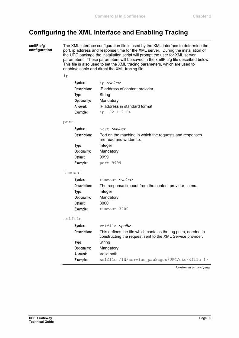
The XML interface configuration file is used by the XML interface to determine the port, ip address and response time for the XML server. During the installation of the UPC package the installation script will prompt the user for XML server parameters. These parameters will be saved in the xmlIF.cfg file described below. This file is also used to set the XML tracing parameters, which are used to enable/disable and direct the XML tracing file.
ip
Syntax: ip <value>
Description: IP address of content provider.
Type: String
Optionality: Mandatory
Allowed: IP address in standard format
Example: ip 192.1.2.64
port
Syntax: port <value>
Description: Port on the machine in which the requests and responses are read and written to.
Type: Integer
Optionality: Mandatory
Default: 9999
Example: port 9999
timeout
Syntax: timeout <value>
Description: The response timeout from the content provider, in ms.
Type: Integer
Optionality: Mandatory
Default: 3000
Example: timeout 3000
xmlfile
Syntax: xmlfile <path>
Description: This defines the file which contains the tag pairs, needed in constructing the request sent to the XML Service provider.
Type: String
Optionality: Mandatory
Allowed: Valid path
Example: xmlfile /IN/service_packages/UPC/etc/<file 1>
Continued on next page
xmlIF.cfg configuration
Chapter 2 Commercial In Confidence
Configuring the XML Interface and Enabling Tracing, Continued
Page 40 USSD Gateway Technical Guide
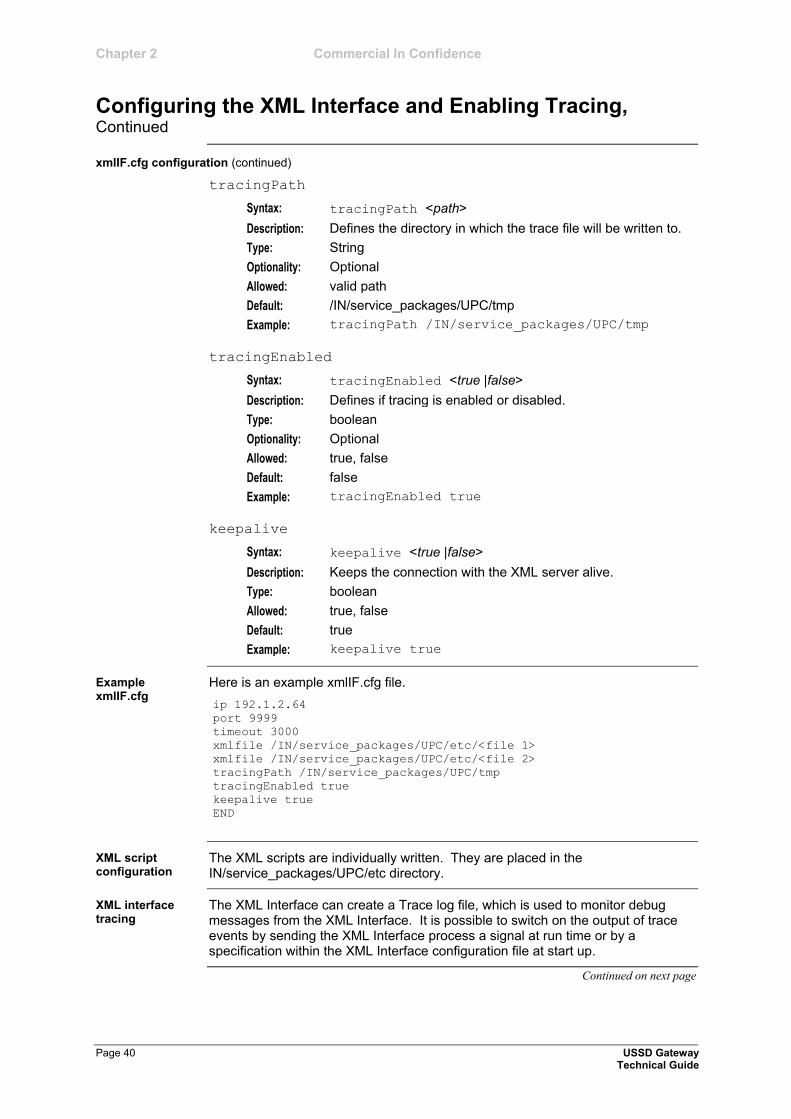
xmlIF.cfg configuration (continued)
tracingPath
Syntax: tracingPath <path>
Description: Defines the directory in which the trace file will be written to.
Type: String
Optionality: Optional
Allowed: valid path
Default: /IN/service_packages/UPC/tmp
Example: tracingPath /IN/service_packages/UPC/tmp
tracingEnabled
Syntax: tracingEnabled <true |false>
Description: Defines if tracing is enabled or disabled.
Type: boolean
Optionality: Optional
Allowed: true, false
Default: false
Example: tracingEnabled true
keepalive
Syntax: keepalive <true |false>
Description: Keeps the connection with the XML server alive.
Type: boolean
Allowed: true, false
Default: true
Example: keepalive true
Here is an example xmlIF.cfg file.
ip 192.1.2.64
port 9999
timeout 3000
xmlfile /IN/service_packages/UPC/etc/<file 1>
xmlfile /IN/service_packages/UPC/etc/<file 2>
tracingPath /IN/service_packages/UPC/tmp
tracingEnabled true
keepalive true
END
The XML scripts are individually written. They are placed in the IN/service_packages/UPC/etc directory.
The XML Interface can create a Trace log file, which is used to monitor debug messages from the XML Interface. It is possible to switch on the output of trace events by sending the XML Interface process a signal at run time or by a specification within the XML Interface configuration file at start up.
Continued on next page
Example xmlIF.cfg
XML script configuration
XML interface tracing
Commercial In Confidence Chapter 2
Configuring the XML Interface and Enabling Tracing, Continued
USSD Gateway Page 41 Technical Guide
XML interface tracing (continued)
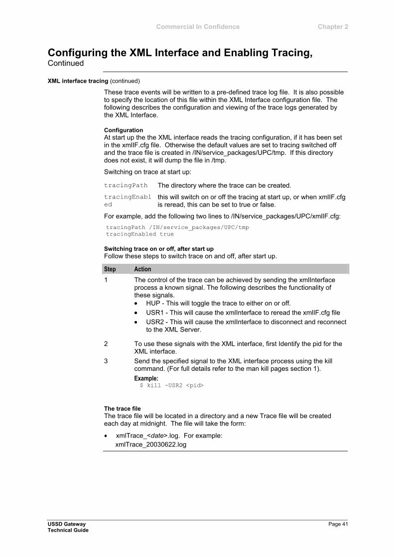
These trace events will be written to a pre-defined trace log file. It is also possible to specify the location of this file within the XML Interface configuration file. The following describes the configuration and viewing of the trace logs generated by the XML Interface.
Configuration
At start up the the XML interface reads the tracing configuration, if it has been set in the xmlIF.cfg file. Otherwise the default values are set to tracing switched off and the trace file is created in /IN/service_packages/UPC/tmp. If this directory does not exist, it will dump the file in /tmp.
Switching on trace at start up:
tracingPath The directory where the trace can be created.
tracingEnabl
ed this will switch on or off the tracing at start up, or when xmlIF.cfg is reread, this can be set to true or false.
For example, add the following two lines to /IN/service_packages/UPC/xmlIF.cfg:
tracingPath /IN/service_packages/UPC/tmp
tracingEnabled true
Switching trace on or off, after start up
Follow these steps to switch trace on and off, after start up.
Step Action
1 The control of the trace can be achieved by sending the xmlInterface process a known signal. The following describes the functionality of these signals.
HUP - This will toggle the trace to either on or off.
USR1 - This will cause the xmlInterface to reread the xmlIF.cfg file
USR2 - This will cause the xmlInterface to disconnect and reconnect to the XML Server.
2 To use these signals with the XML interface, first Identify the pid for the XML interface.
3 Send the specified signal to the XML interface process using the kill command. (For full details refer to the man kill pages section 1).
Example: $ kill -USR2 <pid>
The trace file
The trace file will be located in a directory and a new Trace file will be created each day at midnight. The file will take the form:
xmlTrace_<date>.log. For example:
xmlTrace_20030622.log

Commercial In Confidence
USSD Gateway Page 43 Technical Guide
Background Processes
Overview
This chapter explains the processes which run automatically as part of the application. These processes are started automatically by one of the following:
inittab
crontab, or
SLEE.
Note: This chapter also includes some plugins to background processes which do not run independently.
This chapter contains the following topics.
ussdgw .......................................................................................................... 44 UssdMfileD .................................................................................................... 45 libupcService ................................................................................................. 46 libupcChassisActions .................................................................................... 47 libupcMacroNodes ......................................................................................... 48 cdrLoader ...................................................................................................... 49
Chapter 3
Introduction
In this chapter

Chapter 3 Commercial In Confidence
Page 44 USSD Gateway Technical Guide
ussdgw
The ussdgw process is the main USSD GW binary. It:
translates incoming USSD messages into INAP messages which are passed to a SLEE application (such as slee_acs)
determines which service key an incoming USSD message should trigger to in the SLEE, and
translates INAP play announcements and PACUI messages into USSD messages and forwards them to the external interface.
This binary is located on SLCs.
This task is started by the SLEE, by lines like the following in SLEE.cfg:
APPLICATION=ussdgw ussdgw.sh /IN/service_packages/UIS/bin 1 1
SERVICE=ussdgw 1 ussdgw ussdgw
SERVICEKEY=INTEGER 10 ussdgw
Notes:
Actual value and startup script name may vary.
For more information about this SLEE.cfg configuration, see SLEE Technical Guide.
ussdgw is configured using the command line. For more information about the available parameters, see Gateway configuration (on page 17) and eserv.config Configuration (on page 24).
Purpose
Location
Startup
Configuration
Commercial In Confidence Chapter 3
USSD Gateway Page 45 Technical Guide
UssdMfileD
UssdMfileD maintains all USSD Gateway MFiles. It is installed with UIS.
Note: The MFiles contain a sub-set of the configuration data (such as triggering rules) entered through the UPC and UIS system management screens. This data is stored in a form optimised for fast lookup by ussdgw (on page 44).
This binary is located on SLCs.
This task is started twice (by entries uis0 and uis1 in the inittab). Each entry uses a different startup shell script. They are:
/IN/service_packages/UIS/bin/uisMfileOPStartup.sh
/IN/service_packages/UIS/bin/uisMfileTRStartup.sh
UssdMfileD supports these parameters from command line:
UssdMfileD -user <uid>/<pwd> -name <name>
-user
Syntax: -user <usr>/<pwd>
Description: The oracle userid and password to log into the database.
Type: String
Optionality: Optional (default used if not set).
Default: /
-name
Syntax: -name <name>
Description: The filename of the MFile.
Optionality: Mandatory
Default: None
Example: UssdMfileD -user smf/smf -name
UIS_OPERATOR_INFO_MFILE
UssdMfileD -user smf/smf -name
UIS_SVC_TRIGGER_MFILE
UssdMfileD writes alarms and other messages to the syslog and to:
/IN/service_packages/UIS/tmp/uisMfileOP.log
/IN/service_packages/UIS/tmp/uisMfileTR.log
Purpose
Location
Startup
Configuration
Output
Chapter 3 Commercial In Confidence
Page 46 USSD Gateway Technical Guide
libupcService
libupcService is the USSD GW service library plugin for slee_acs which handles initial set up of USSD call control plans. It:
sets up USSD GW call processing (including populating the call context from the IDP), and
used the eserv.config and USSD GW screens configuration to determine the correct control plan to load and run from cache.
This library is located on SLCs.
If libupcService is configured in acs.conf, it is made available to slee_acs when slee_acs is initialised. It is included in the acsChassis section of acs.conf in a ServiceEntry.
acsChassis
ServiceEntry (UPC,C,c,libupcService.so)
libupcService is configured in the upcServiceLoader section of the upc.conf file.
For more information about this configuration, see Configuring the USSD Gateway Portal Component (UPC) (on page 21).
Purpose
Location
Startup
Configuration - libupcService - 1.0- ; #lgcy

Commercial In Confidence Chapter 3
USSD Gateway Page 47 Technical Guide
libupcChassisActions
libupcChassisActions provides the functions which enable the USSD GW Feature Nodes to interact with other elements in the system, including ussdgw.
This library is located on SLCs.
If libupcChassisActions is configured in acs.conf, it is made available to slee_acs when slee_acs is initialised. It is included in the acsChassis section of acs.conf in a ChassisPlugin entry.
acsChassis
ChassisPlugin libupcChassisActions.so
This binary has no specific configuration.
Purpose
Location
Startup
Configuration
Chapter 3 Commercial In Confidence
Page 48 USSD Gateway Technical Guide
libupcMacroNodes
This slee_acs plugin provides the USSD GW macro nodes. There are no configuration file settings for these macro nodes, they are all configured in the Control Plan Editor node configuration screens.
For more information about the feature nodes provided by this library, see USSD GW User's Guide.
For more information about macro node libraries, see ACS Technical Guide.
For more information about the CPE, see CPE User's Guide.
This library is located on SLCs.
If libupcMacroNodes is configured in acs.conf, it is made available to slee_acs when slee_acs is initialised. It is included in the acsChassis section of acs.conf in a MacroNodePluginFile entry as follows:
acsChassis
MacroNodePluginFile libupcMacroNodes.so
This binary has no specific configuration.
Purpose
Location
Startup
Configuration
Commercial In Confidence Chapter 3
USSD Gateway Page 49 Technical Guide
cdrLoader
cdrLoader reads EDR files or standard input and inserts records into SMF database.
Required to view EDRs in CDR Viewer screen.
This binary is located on SMSs.
This task is run in the crontab for acs_oper, by default every minute. It is scheduled as the following script:
/IN/service_packages/UIS/bin/cdrLoaderCron.sh
The script runs the cdrLoader process with set parameters. cdrLoaderCron.sh will not start another cdrLoader process if one is already running.
cdrLoader supports these parameters from cdrLoader.conf.
username=<usr>
password=<pwd>
nsname=<nsname>
Note: cdrLoader will not start if cdrLoader.conf cannot be found.
username
Syntax: username=<usr>
Description: The userid to use for logging into the SMF database.
Example: username=SMF
password
Syntax: password=<pwd>
Description: The password to use for logging into the SMF database.
Example: password=PWD
nsname
Syntax: nsname=<nsname>
Optionality: Optional.
Notes: Operator can also set nsname as it appears in tnsnames.ora
Purpose
Location
Startup
Configuration

Commercial In Confidence
USSD Gateway Page 51 Technical Guide
Administrative Tasks
Overview
This chapter explains the procedures for administering the USSD Gateway application.
This chapter contains the following topics.
Starting and Stopping the USSD Gateway ................................................... 52
Chapter 4
Introduction
In this chapter
Chapter 4 Commercial In Confidence
Page 52 USSD Gateway Technical Guide
Starting and Stopping the USSD Gateway
This topic explains how to start or stop the USSD Gateway application.
Follow these steps to start the automated shell script.
Note: You must be logged in as the user acs_oper.
Step Action
1 Type /IN/service_packages/SLEE/bin/slee.sh
Result: This shell script starts the slee_acs and the associated interfaces ussdgw, timer IF and cdrIF.
The stdout and stderr from slee.sh will appear on the screen, so if this screen is closed the output will no longer be viewable. If this information is required then redirect output to a file, e.g. slee.sh > sleeout.log
When the SLEE service starts various information is presented on stdout and the syslog.
Follow these steps to stop the USSD Gateway service.
Note: You must be logged in as the user acs_oper.
Step Action
1 Type /IN/service_packages/SLEE/bin/stop.sh
Note: It also recommended to run a ./clean following the stop.
If the SLEE_FILE variable is being used it must be visible to the stop program. If it is not visible, the program will not be able to clear the shared memory and will exit with error 3005.
Note: If the service has stopped for any abnormal reasons, a manual cleanup should be performed, .i.e. ps –fu acs_oper to find the remaining processes, then kill <pid> each one. The shared memory should be checked using ipcs | grep abs, then remove acs_oper owned ones using ipcrm.
Introduction
Starting the SLEE
Startup output
Stopping the USSD Gateway service
Commercial In Confidence
USSD Gateway Page 53 Technical Guide
Troubleshooting
Overview
This chapter explains the important processes on each of the server components in the NCC, and a number of example troubleshooting methods which will help aid the troubleshooting process before raising a Support Ticket.
This chapter contains the following topics.
Common Troubleshooting Procedures ......................................................... 54 Scenarios ...................................................................................................... 55
Chapter 5
Introduction
In this chapter
Chapter 5 Commercial In Confidence
Page 54 USSD Gateway Technical Guide
Common Troubleshooting Procedures
Refer to the NCC System Administrator's Guide for troubleshooting procedures common to all NCC components.
Debug Logging (debugging) can be enabled on an IMSI basis. The output from specific debugs are written to files with names derived from what is being debugged.
Introduction
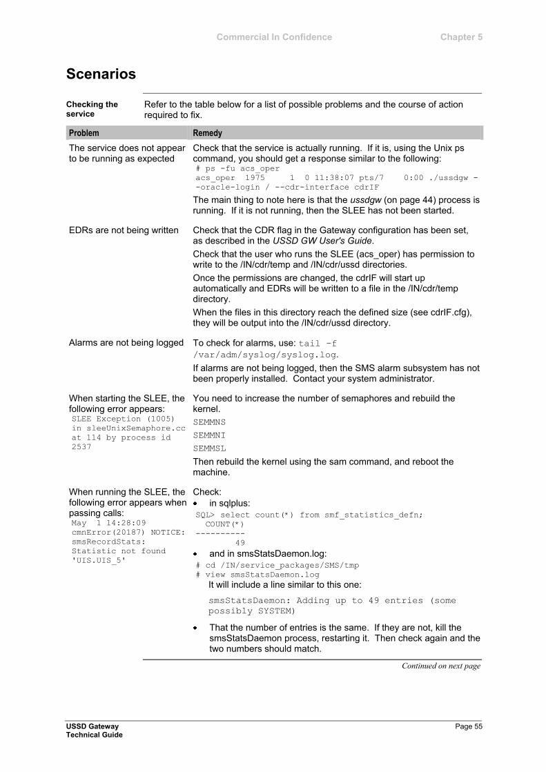
Commercial In Confidence Chapter 5
USSD Gateway Page 55 Technical Guide
Scenarios
Refer to the table below for a list of possible problems and the course of action required to fix.
Problem Remedy
The service does not appear to be running as expected
Check that the service is actually running. If it is, using the Unix ps command, you should get a response similar to the following: # ps -fu acs_oper
acs_oper 1975 1 0 11:38:07 pts/7 0:00 ./ussdgw -
-oracle-login / --cdr-interface cdrIF
The main thing to note here is that the ussdgw (on page 44) process is running. If it is not running, then the SLEE has not been started.
EDRs are not being written Check that the CDR flag in the Gateway configuration has been set, as described in the USSD GW User's Guide.
Check that the user who runs the SLEE (acs_oper) has permission to write to the /IN/cdr/temp and /IN/cdr/ussd directories.
Once the permissions are changed, the cdrIF will start up automatically and EDRs will be written to a file in the /IN/cdr/temp directory.
When the files in this directory reach the defined size (see cdrIF.cfg), they will be output into the /IN/cdr/ussd directory.
Alarms are not being logged To check for alarms, use: tail –f
/var/adm/syslog/syslog.log.
If alarms are not being logged, then the SMS alarm subsystem has not been properly installed. Contact your system administrator.
When starting the SLEE, the following error appears: SLEE Exception (1005)
in sleeUnixSemaphore.cc
at 114 by process id
2537
You need to increase the number of semaphores and rebuild the kernel.
SEMMNS
SEMMNI
SEMMSL
Then rebuild the kernel using the sam command, and reboot the machine.
When running the SLEE, the following error appears when passing calls: May 1 14:28:09
cmnError(20187) NOTICE:
smsRecordStats:
Statistic not found
'UIS.UIS_5'
Check:
in sqlplus:
SQL> select count(*) from smf_statistics_defn;
COUNT(*)
----------
49
and in smsStatsDaemon.log:
# cd /IN/service_packages/SMS/tmp
# view smsStatsDaemon.log
It will include a line similar to this one:
smsStatsDaemon: Adding up to 49 entries (some
possibly SYSTEM)
That the number of entries is the same. If they are not, kill the smsStatsDaemon process, restarting it. Then check again and the two numbers should match.
Continued on next page
Checking the service
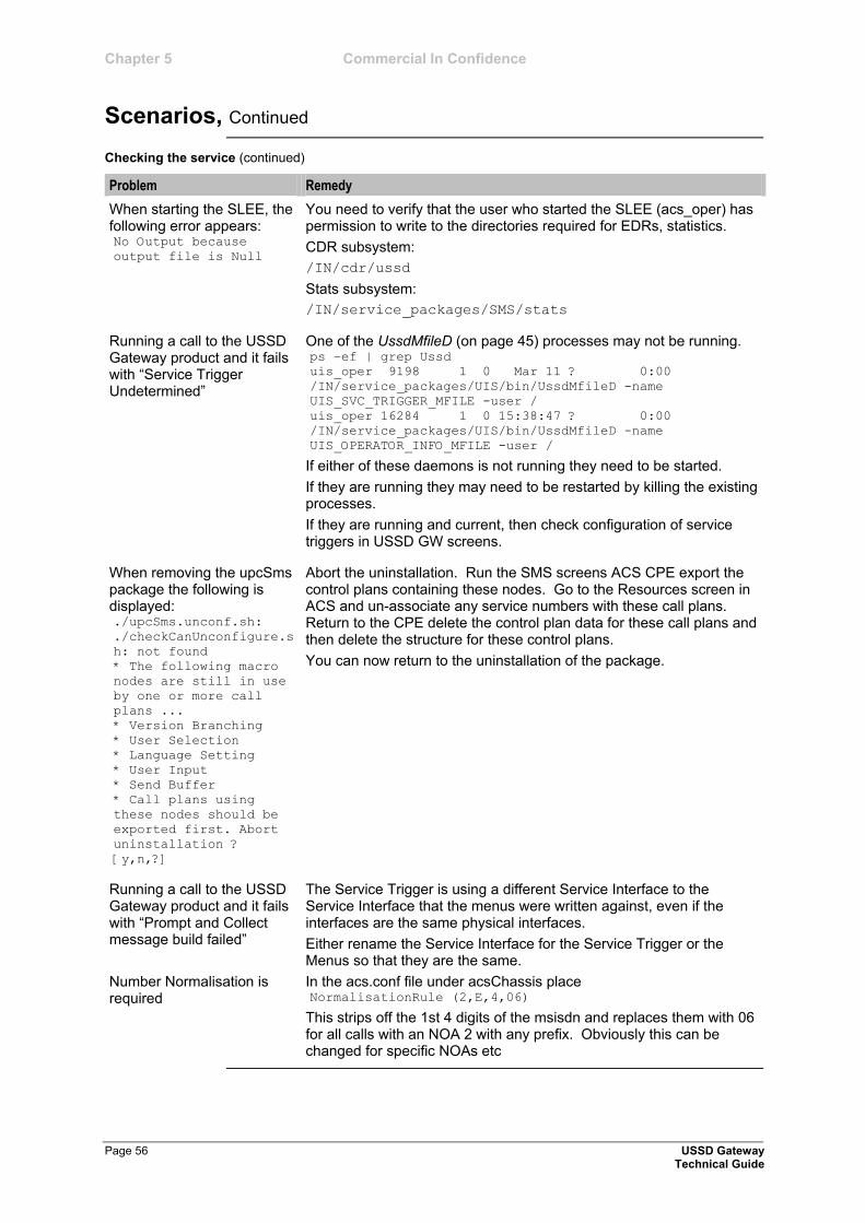
Chapter 5 Commercial In Confidence
Scenarios, Continued
Page 56 USSD Gateway Technical Guide
Checking the service (continued)
Problem Remedy
When starting the SLEE, the following error appears: No Output because
output file is Null
You need to verify that the user who started the SLEE (acs_oper) has permission to write to the directories required for EDRs, statistics.
CDR subsystem:
/IN/cdr/ussd
Stats subsystem:
/IN/service_packages/SMS/stats
Running a call to the USSD Gateway product and it fails with ―Service Trigger Undetermined‖
One of the UssdMfileD (on page 45) processes may not be running. ps –ef | grep Ussd
uis_oper 9198 1 0 Mar 11 ? 0:00
/IN/service_packages/UIS/bin/UssdMfileD -name
UIS_SVC_TRIGGER_MFILE -user /
uis_oper 16284 1 0 15:38:47 ? 0:00
/IN/service_packages/UIS/bin/UssdMfileD -name
UIS_OPERATOR_INFO_MFILE -user /
If either of these daemons is not running they need to be started.
If they are running they may need to be restarted by killing the existing processes.
If they are running and current, then check configuration of service triggers in USSD GW screens.
When removing the upcSms package the following is displayed: ./upcSms.unconf.sh:
./checkCanUnconfigure.s
h: not found
* The following macro
nodes are still in use
by one or more call
plans ...
* Version Branching
* User Selection
* Language Setting
* User Input
* Send Buffer
* Call plans using
these nodes should be
exported first. Abort
uninstallation ?
[y,n,?]
Abort the uninstallation. Run the SMS screens ACS CPE export the control plans containing these nodes. Go to the Resources screen in ACS and un-associate any service numbers with these call plans. Return to the CPE delete the control plan data for these call plans and then delete the structure for these control plans.
You can now return to the uninstallation of the package.
Running a call to the USSD Gateway product and it fails with ―Prompt and Collect message build failed‖
The Service Trigger is using a different Service Interface to the Service Interface that the menus were written against, even if the interfaces are the same physical interfaces.
Either rename the Service Interface for the Service Trigger or the Menus so that they are the same.
Number Normalisation is required
In the acs.conf file under acsChassis place NormalisationRule (2,E,4,06)
This strips off the 1st 4 digits of the msisdn and replaces them with 06 for all calls with an NOA 2 with any prefix. Obviously this can be changed for specific NOAs etc
Commercial In Confidence
USSD Gateway Page 57 Technical Guide
Installation and Removal
Overview
This chapter provides details of the installation and removal process for the application.
This chapter contains the following topics.
Installation and Removal Overview ............................................................... 58 CDR Loader Deployment .............................................................................. 59 Post-installation Configuration ...................................................................... 61 Checking Removal ........................................................................................ 63
Chapter 6
Introduction
In this chapter
Chapter 6 Commercial In Confidence
Page 58 USSD Gateway Technical Guide
Installation and Removal Overview
For details about:
NCC system requirements,
pre-installation tasks, and
installing and removing NCC packages,
refer to NCC Installation Guide.
An installation of the USSD Gateway includes the following packages, on the:
SMS:
uisSms upcSms
SLC:
uisScp upcScp
Introduction
USSD Gateway packages
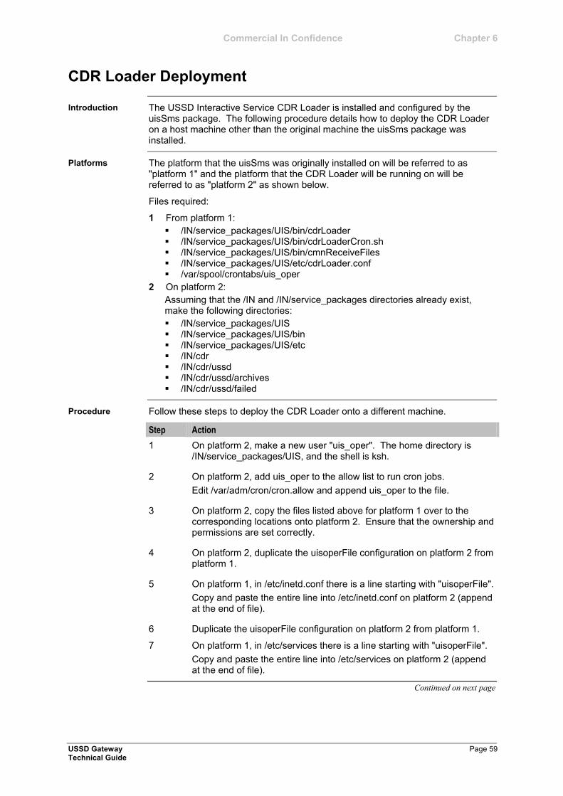
Commercial In Confidence Chapter 6
USSD Gateway Page 59 Technical Guide
CDR Loader Deployment
The USSD Interactive Service CDR Loader is installed and configured by the uisSms package. The following procedure details how to deploy the CDR Loader on a host machine other than the original machine the uisSms package was installed.
The platform that the uisSms was originally installed on will be referred to as "platform 1" and the platform that the CDR Loader will be running on will be referred to as "platform 2" as shown below.
Files required:
1 From platform 1:
/IN/service_packages/UIS/bin/cdrLoader /IN/service_packages/UIS/bin/cdrLoaderCron.sh /IN/service_packages/UIS/bin/cmnReceiveFiles /IN/service_packages/UIS/etc/cdrLoader.conf /var/spool/crontabs/uis_oper
2 On platform 2:
Assuming that the /IN and /IN/service_packages directories already exist, make the following directories:
/IN/service_packages/UIS /IN/service_packages/UIS/bin /IN/service_packages/UIS/etc /IN/cdr /IN/cdr/ussd /IN/cdr/ussd/archives /IN/cdr/ussd/failed
Follow these steps to deploy the CDR Loader onto a different machine.
Step Action
1 On platform 2, make a new user "uis_oper". The home directory is /IN/service_packages/UIS, and the shell is ksh.
2 On platform 2, add uis_oper to the allow list to run cron jobs.
Edit /var/adm/cron/cron.allow and append uis_oper to the file.
3 On platform 2, copy the files listed above for platform 1 over to the corresponding locations onto platform 2. Ensure that the ownership and permissions are set correctly.
4 On platform 2, duplicate the uisoperFile configuration on platform 2 from platform 1.
5 On platform 1, in /etc/inetd.conf there is a line starting with "uisoperFile".
Copy and paste the entire line into /etc/inetd.conf on platform 2 (append at the end of file).
6 Duplicate the uisoperFile configuration on platform 2 from platform 1.
7 On platform 1, in /etc/services there is a line starting with "uisoperFile".
Copy and paste the entire line into /etc/services on platform 2 (append at the end of file).
Continued on next page
Introduction
Platforms
Procedure
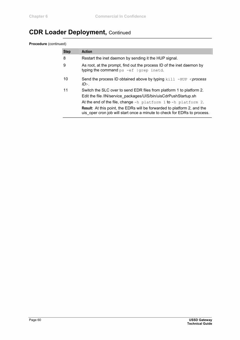
Chapter 6 Commercial In Confidence
CDR Loader Deployment, Continued
Page 60 USSD Gateway Technical Guide
Procedure (continued)
Step Action
8 Restart the inet daemon by sending it the HUP signal.
9 As root, at the prompt, find out the process ID of the inet daemon by
typing the command ps -ef |grep inetd.
10 Send the process ID obtained above by typing kill -HUP <process
ID>.
11 Switch the SLC over to send EDR files from platform 1 to platform 2.
Edit the file /IN/service_packages/UIS/bin/uisCdrPushStartup.sh
At the end of the file, change -h platform 1 to -h platform 2.
Result: At this point, the EDRs will be forwarded to platform 2, and the uis_oper cron job will start once a minute to check for EDRs to process.
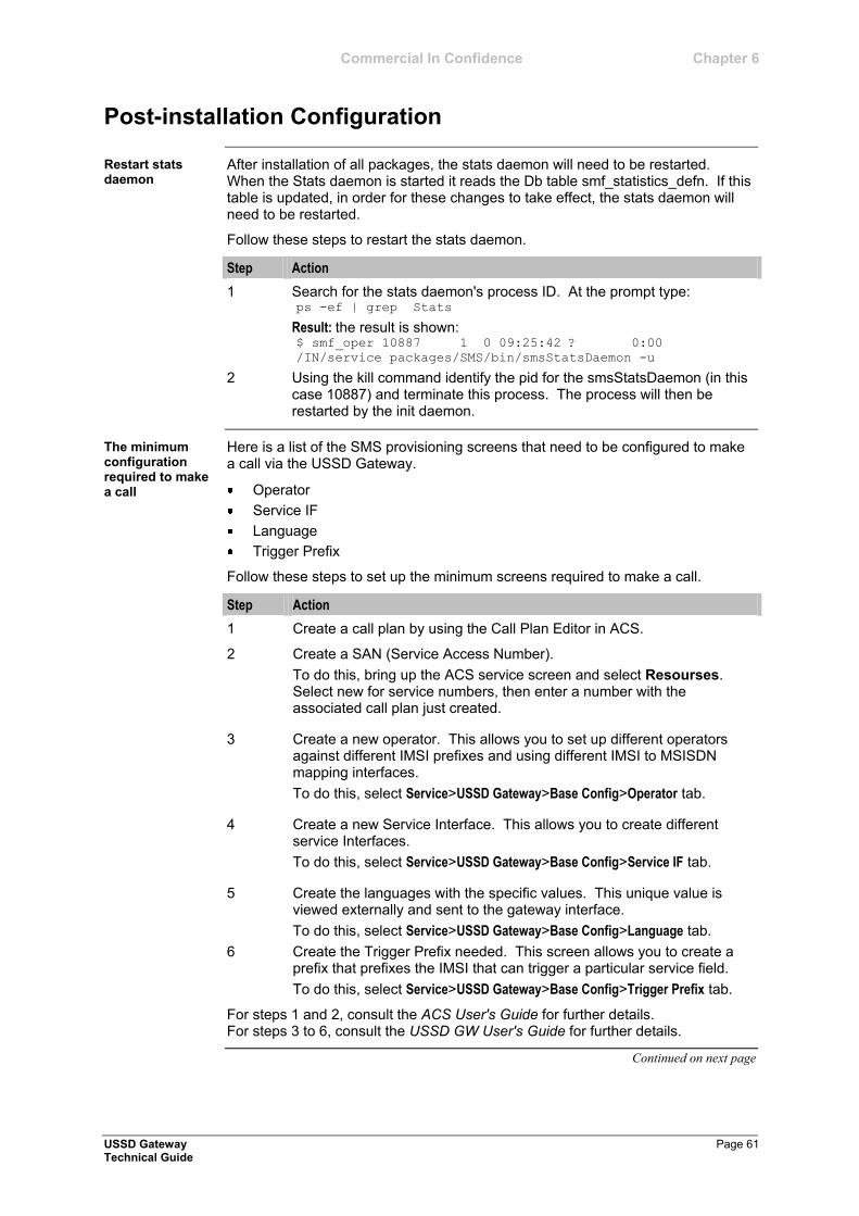
Commercial In Confidence Chapter 6
USSD Gateway Page 61 Technical Guide
Post-installation Configuration
After installation of all packages, the stats daemon will need to be restarted. When the Stats daemon is started it reads the Db table smf_statistics_defn. If this table is updated, in order for these changes to take effect, the stats daemon will need to be restarted.
Follow these steps to restart the stats daemon.
Step Action
1 Search for the stats daemon's process ID. At the prompt type: ps -ef | grep Stats
Result: the result is shown: $ smf_oper 10887 1 0 09:25:42 ? 0:00
/IN/service_packages/SMS/bin/smsStatsDaemon -u
2 Using the kill command identify the pid for the smsStatsDaemon (in this case 10887) and terminate this process. The process will then be restarted by the init daemon.
Here is a list of the SMS provisioning screens that need to be configured to make a call via the USSD Gateway.
Operator
Service IF
Language
Trigger Prefix
Follow these steps to set up the minimum screens required to make a call.
Step Action
1 Create a call plan by using the Call Plan Editor in ACS.
2 Create a SAN (Service Access Number).
To do this, bring up the ACS service screen and select Resourses. Select new for service numbers, then enter a number with the associated call plan just created.
3 Create a new operator. This allows you to set up different operators against different IMSI prefixes and using different IMSI to MSISDN mapping interfaces.
To do this, select Service>USSD Gateway>Base Config>Operator tab.
4 Create a new Service Interface. This allows you to create different service Interfaces.
To do this, select Service>USSD Gateway>Base Config>Service IF tab.
5 Create the languages with the specific values. This unique value is viewed externally and sent to the gateway interface.
To do this, select Service>USSD Gateway>Base Config>Language tab.
6 Create the Trigger Prefix needed. This screen allows you to create a prefix that prefixes the IMSI that can trigger a particular service field.
To do this, select Service>USSD Gateway>Base Config>Trigger Prefix tab.
For steps 1 and 2, consult the ACS User's Guide for further details. For steps 3 to 6, consult the USSD GW User's Guide for further details.
Continued on next page
Restart stats daemon
The minimum configuration required to make a call
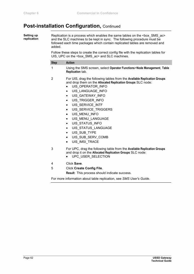
Chapter 6 Commercial In Confidence
Post-installation Configuration, Continued
Page 62 USSD Gateway Technical Guide
Replication is a process which enables the same tables on the <box_SMS_ac> and the SLC machines to be kept in sync. The following procedure must be followed each time packages which contain replicated tables are removed and added.
Follow these steps to create the correct config file with the replication tables for UIS, UPC on the <box_SMS_ac> and SLC machines.
Step Action
1 Using the SMS screen, select Operator Functions>Node Management, Table Replication tab.
2 For UIS, drag the following tables from the Available Replication Groups and drop them on the Allocated Replication Groups SLC node:
UIS_OPERATOR_INFO
UIS_LANGUAGE_INFO
UIS_GATEWAY_INFO
UIS_TRIGGER_INFO
UIS_SERVICE_INTF
UIS_SERVICE_TRIGGERS
UIS_MENU_INFO
UIS_MENU_LANGUAGE
UIS_STATUS_INFO
UIS_STATUS_LANGUAGE
UIS_SUB_TYPE
UIS_SUB_SERV_COMB
UIS_IMSI_TRACE
3 For UPC, drag the following table from the Available Replication Groups and drop it on the Allocated Replication Groups SLC node:
UPC_USER_SELECTION
4 Click Save.
5 Click Create Config File.
Result: This process should indicate success.
For more information about table replication, see SMS User's Guide.
Setting up replication
Commercial In Confidence Chapter 6
USSD Gateway Page 63 Technical Guide
Checking Removal
After the un-installs have completed, it is worth double checking the /IN/service_packages/ directory to ensure the UIS, and UPC directories have gone.
Follow these steps to check that the tables have gone.
Step Action
1 As sms_oper, start SQL Plus.
2 Type: sqlplus /
select table_name from all_tables where_name like 'U%';
and make sure there are no UIS tables in the list.
Introduction
Procedure


Commercial In Confidence
USSD Gateway Page 65 Technical Guide
Appendix
Overview
This appendix contains the following topics.
Glossary of Terms ......................................................................................... 67 Index .............................................................................................................. 73
In this appendix

Commercial In Confidence
USSD Gateway Page 67 Technical Guide
Glossary of Terms
Authentication, Authorization, and Accounting. Specified in Diameter RFC 3588.
Advanced Control Services configuration platform.
Basic Call State Model - describes the basic processing steps that must be performed by a switch in order to establish and tear down a call.
Customized Applications for Mobile network Enhanced Logic
This is a 3GPP (Third Generation Partnership Project) initiative to extend traditional IN services found in fixed networks into mobile networks. The architecture is similar to that of traditional IN, in that the control functions and switching functions are remote. Unlike the fixed IN environment, in mobile networks the subscriber may roam into another PLMN (Public Land Mobile Network), consequently the controlling function must interact with a switching function in a foreign network. CAMEL specifies the agreed information flows that may be passed between these networks.
Country Code. Prefix identifying the country for a numeric international address.
1) Charging Control Services (or Prepaid Charging) component.
2) Common Channel Signalling. A signalling system used in telephone networks that separates signalling information from user data.
Call Detail Record
Note: The industry standard for CDR is EDR (Event Detail Record). Over time EDR will replace CDR in the Oracle documentation.
Control Plan Editor (previously Call Plan Editor) - software used to define the logic and data associated with a call -for example, "if the subscriber calls 0800 nnnnnn from a phone at location xxx then put the call through to bb bbb bbbb".
Unix utility for scheduling tasks.
File used by cron.
Character User Interface
A feature rich AAA protocol. Utilises SCTP and TCP transports.
Detection Point
Event Detail Record
Note: Previously CDR. The industry standard for CDR is EDR (Event Detail Record). Over time EDR will replace CDR in the Oracle documentation.
First Delivery Attempt - the delivery of a short message directly to the SME rather than relaying it via the MC.
General Packet Radio Service - employed to connect mobile cellular users to PDN (Public Data Network- for example the Internet).
AAA
ACS
BCSM
CAMEL
CC
CCS
CDR
CPE
cron
crontab
CUI
Diameter
DP
EDR
FDA
GPRS
Commercial In Confidence
Page 68 USSD Gateway Technical Guide
Global System for Mobile communication.
It is a second generation cellular telecommunication system. Unlike first generation systems, GSM is digital and thus introduced greater enhancements such as security, capacity, quality and the ability to support integrated services.
The Home Location Register is a database within the HPLMN (Home Public Land Mobile Network). It provides routing information for MT calls and SMS. It is also responsible for the maintenance of user subscription information. This is distributed to the relevant VLR, or SGSN (Serving GPRS Support Node) through the attach process and mobility management procedures such as Location Area and Routing Area updates.
Home PLMN
HyperText Markup Language, a small application of SGML used on the World Wide Web.
It defines a very simple class of report-style documents, with section headings, paragraphs, lists, tables, and illustrations, with a few informational and presentational items, and some hypertext and multimedia.
InitiateCallAttempt. A CAMEL/INAP operation sent by the SLC to an SSP request that a voice call is started.
INAP message: Initial DP (Initial Detection Point)
International Mobile Subscriber Identifier. A unique identifier allocated to each mobile subscriber in a GSM and UMTS network. It consists of a MCC (Mobile Country Code), a MNC (Mobile Network Code) and a MSIN (Mobile Station Identification Number).
The IMSI is returned by the HLR query (SRI-SM) when doing FDA. This tells the MSC exactly who the subscriber is that the message is to be sent to.
Intelligent Network
Intelligent Network Application Part - a protocol offering real time communication between IN elements.
Initial Detection Point - INAP Operation. This is the operation that is sent when the switch reaches a trigger detection point.
1) Internet Protocol
2) Intelligent Peripheral - a box that is able to play announcements
Internet Protocol Address - network address of a card on a computer
Integrated Services Digital Network - set of protocols for connecting ISDN stations.
International Telecommunication Union
Mobile Application Part - a protocol which enables real time communication between nodes in a mobile cellular network. A typical usage of the protocol would be for the transfer of location information from the VLR to the HLR.
Message Centre. Also known as SMSC.
GSM
HLR
HPLMN
HTML
ICA
IDP
IMSI
IN
INAP
Initial DP
IP
IP address
ISDN
ITU
MAP
MC
Commercial In Confidence
USSD Gateway Page 69 Technical Guide
Mobile Country Code. In the location information context, this is padded to three digits with leading zeros. Refer to ITU E.212 ("Land Mobile Numbering Plan") documentation for a list of codes.
Mobile Network Code. The part of an international address following the mobile country code (MCC), or at the start of a national format address. This specifies the mobile network code, that is, the operator owning the address. In the location information context, this is padded to two digits with a leading zero. Refer to ITU E.212 ("Land Mobile Numbering Plan") documentation for a list of codes.
Mobile Station
Mobile Switching Centre. Also known as a switch.
Mobile Station Identification Number.
Mobile Station ISDN number. Uniquely defines the mobile station as an ISDN terminal. It consists of three parts; the country code (CC), the national destination code (NDC) and the subscriber number (SN).
Mobile Station Roaming Number
Mobile Terminated
Nature Of Address - a classification to determine in what realm (Local, National or International) a given phone number resides, for the purposes of routing and billing.
Oracle Corporation
Play Announcement and Collect User Information
Public Land Mobile Network
Request Report BCSM.
Service Access Number
Service Control Point. Also known as SLC.
Stream Control Transmission Protocol. A transport-layer protocol analogous to the TCP or User Datagram Protocol (UDP). SCTP provides some similar services as TCP (reliable, in-sequence transport of messages with congestion control) but adds high availability.
Diameter exchange relating to a particular user or subscriber access to a provided service (for example, a telephone call).
Standard Generalized Markup Language. The international standard for defining descriptions of the structure of different types of electronic document.
Serving GPRS Support Node
Service Logic Controller (formerly UAS).
MCC
MNC
MS
MSC
MSIN
MSISDN
MSRN
MT
NOA
Oracle
PACUI
PLMN
RRBCSM
SAN
SCP
SCTP
Session
SGML
SGSN
SLC
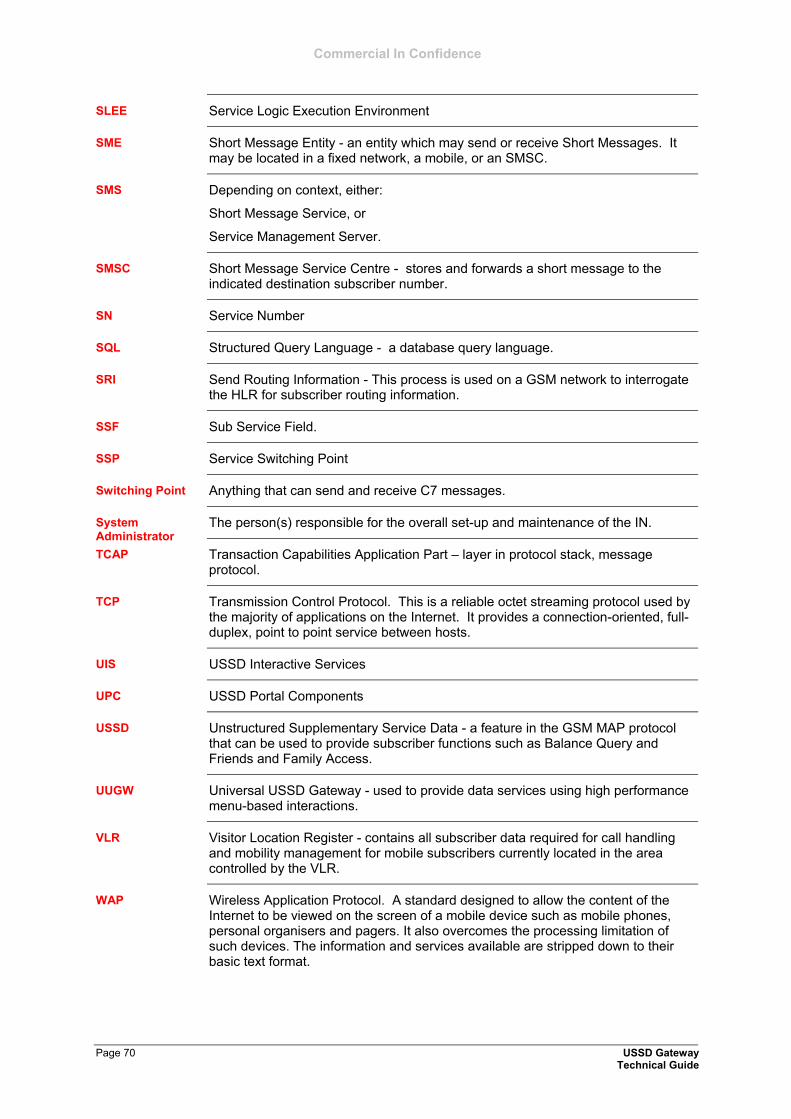
Commercial In Confidence
Page 70 USSD Gateway Technical Guide
Service Logic Execution Environment
Short Message Entity - an entity which may send or receive Short Messages. It may be located in a fixed network, a mobile, or an SMSC.
Depending on context, either:
Short Message Service, or
Service Management Server.
Short Message Service Centre - stores and forwards a short message to the indicated destination subscriber number.
Service Number
Structured Query Language - a database query language.
Send Routing Information - This process is used on a GSM network to interrogate the HLR for subscriber routing information.
Sub Service Field.
Service Switching Point
Anything that can send and receive C7 messages.
The person(s) responsible for the overall set-up and maintenance of the IN.
Transaction Capabilities Application Part – layer in protocol stack, message protocol.
Transmission Control Protocol. This is a reliable octet streaming protocol used by the majority of applications on the Internet. It provides a connection-oriented, full-duplex, point to point service between hosts.
USSD Interactive Services
USSD Portal Components
Unstructured Supplementary Service Data - a feature in the GSM MAP protocol that can be used to provide subscriber functions such as Balance Query and Friends and Family Access.
Universal USSD Gateway - used to provide data services using high performance menu-based interactions.
Visitor Location Register - contains all subscriber data required for call handling and mobility management for mobile subscribers currently located in the area controlled by the VLR.
Wireless Application Protocol. A standard designed to allow the content of the Internet to be viewed on the screen of a mobile device such as mobile phones, personal organisers and pagers. It also overcomes the processing limitation of such devices. The information and services available are stripped down to their basic text format.
SLEE
SME
SMS
SMSC
SN
SQL
SRI
SSF
SSP
Switching Point
System Administrator
TCAP
TCP
UIS
UPC
USSD
UUGW
VLR
WAP
Commercial In Confidence
USSD Gateway Page 71 Technical Guide
eXtensible Markup Language. It is designed to improve the functionality of the Web by providing more flexible and adaptable information identification.
It is called extensible because it is not a fixed format like HTML. XML is a `metalanguage' — a language for describing other languages—which lets you design your own customized markup languages for limitless different types of documents. XML can do this because it's written in SGML.
XML

Commercial In Confidence
USSD Gateway Page 73 Technical Guide
#
Configuration - libupcService - 1.0- libupcService • 46
A
-a • 19 A leg
Callback • 7 Abbv • 26, 28, 29, 30 About this Document
Audience • v Changes in this document • v Pre-requisites • v Related documents • v Scope • v
ACS • 3, 13, 55 acs.conf • 12 Alarms
Alarms, Statistics, Reports and EDRs • 9 Alarms, Statistics, Reports and EDRs
Alarms • 9 EDRs • 9 Statistics • 9
Audience About this Document • v
B
B leg Callback • 7
BCSM • 69
C
-c <if> • 17
C7 • 70 Call back message flow
Callback • 8 Callback
A leg • 7 B leg • 7 Call back message flow • 8 Callback initiation • 7 Introduction • 7
Callback initiation Callback • 7
CAMEL • 67 CC • 69 CCS • 3 CDR • 2, 37, 55
C,(continued)
CDR Loader Deployment Introduction • 59 Platforms • 59 Procedure • 59
cdrIF.cfg • 12 cdrLoader
Configuration • 49 Location • 49 Purpose • 49 Startup • 49
cdrLoader.conf • 12 Changes in this document
About this Document • v Checking encoding parameters
Configuring acs.conf for the SLC • 15 Checking procedure
Configuring the SLEE.cfg • 13 Checking Removal
Introduction • 63 Procedure • 63
Checking the service Scenarios • 55
Common Troubleshooting Procedures Introduction • 54
Component acs.conf • 12 cdrIF.cfg • 12 cdrLoader.conf • 12 eserv.conifg • 12 SLEE.cfg • 12 SMS screens • 12 upc.conf • 12 ussdgw.sh • 12
Components What is USSD Gateway? • 3
Configuration • 12, 41 cdrLoader • 49 libupcChassisActions • 47 libupcMacroNodes • 48 ussdgw • 44 UssdMfileD • 45
Configuration components Configuration Overview • 12
Configuration file format eserv.config Configuration • 24
Configuration Overview Configuration components • 12 Introduction • 12 Multiple instances of SMSC • 12
Configuring ACS to recognise hex digits Configuring acs.conf for the SLC • 15
Index
Commercial In Confidence
Page 74 USSD Gateway Technical Guide
C,(continued)
Configuring acs.conf for the SLC • 12 Checking encoding parameters • 15 Configuring ACS to recognise hex digits •
15 Introduction • 15 Send Buffer Node - number normalisation •
16 srf configuration • 16 UPC library configuration • 15
Configuring the SLEE.cfg Checking procedure • 13 Editing the SLEE.cfg file • 13 Example SLEE.cfg file • 13 Introduction • 13
Configuring the USSD Gateway Portal Component (UPC) • 12, 46 Default upc.conf file • 21 Introduction • 21 Release calls with no MSISDN instructions
• 23 upcServiceLoader parameters • 21
Configuring the XML Interface and Enabling Tracing Example xmlIF.cfg • 40 XML interface tracing • 40 XML script configuration • 40 xmlIF.cfg configuration • 39
CPE • 7 cron • 59 crontab • 43 CUI • 6
D
DaysOfWeek • 26, 27 Debug • 54 Default upc.conf file
Configuring the USSD Gateway Portal Component (UPC) • 21
defaultLanguageId • 22 destDir • 34 Diagram
What is USSD Gateway? • 2 Diameter • 67 Document Conventions
Icons • vi Typographical conventions • vi
DP • 68
E
-e <opt> • 18
Editing the file eserv.config Configuration • 25
E,(continued)
Editing the SLEE.cfg file Configuring the SLEE.cfg • 13
EDR • 2 EDR Section
Example cdrIF.cfg configuration file • 37 Example config • 34 Introduction • 34, 37 Parameters • 34
EDRs Alarms, Statistics, Reports and EDRs • 9
eserv.config Configuration • 12, 44 Configuration file format • 24 Editing the file • 25 eserv.config files delivered • 25 Introduction • 24 Location of eserv.config • 24
eserv.config files delivered eserv.config Configuration • 25
eserv.conifg • 12 ESERV_CONFIG_FILE • 25 Example 1 • 31 Example 2 • 32 Example call flow
Handset Interaction • 5 Example call flow description
Handset Interaction • 5 Example cdrIF.cfg configuration file
EDR Section • 37 Example config
EDR Section • 34 Example SLEE.cfg file
Configuring the SLEE.cfg • 13 Example xmlIF.cfg
Configuring the XML Interface and Enabling Tracing • 40
Examples • 27, 28, 30 Response Date and Time • 31
F
FDA • 68 filePrefix • 34 flushPeriod • 35 Full • 26, 27, 29, 30
G
Gateway configuration • 12, 44 Overview of the USSD Gateway
Configuration • 17 GPRS • 68 GSM • 4
Commercial In Confidence
USSD Gateway Page 75 Technical Guide
H
Handset integration What is USSD Gateway? • 4
Handset Interaction Example call flow • 5 Example call flow description • 5 Introduction • 5
HLR • 5 HPLMN • 68 HTML • vi
I
ICA • 7 Icons
Document Conventions • vi IDP • 7 IMSI • 2 IN • v INAP • 3 Initial DP • 68 Installation and Removal Overview
Introduction • 58 USSD Gateway packages • 58
Introduction Callback • 7 CDR Loader Deployment • 59 Checking Removal • 63 Common Troubleshooting Procedures • 54 Configuration Overview • 12 Configuring acs.conf for the SLC • 15 Configuring the SLEE.cfg • 13 Configuring the USSD Gateway Portal
Component (UPC) • 21 EDR Section • 34, 37 eserv.config Configuration • 24 Handset Interaction • 5 Installation and Removal Overview • 58 Overview of the USSD Gateway
Configuration • 17 Starting and Stopping the USSD Gateway •
52 What is USSD Gateway? • 2
ip • 39 IP • 39 IP address • 39 ISDN • 68 ITU • 69
K
keepalive • 40
L
-l <usr>/<pwd> • 17
Language • 27, 30 libupcChassisActions • 3, 16
Configuration • 47 Location • 47 Purpose • 47 Startup • 47
libupcMacroNodes • 3, 16 Configuration • 48 Location • 48 Purpose • 48 Startup • 48
libupcService • 3, 16 Configuration - libupcService - 1.0- • 46 Location • 46 Purpose • 46 Startup • 46
Location cdrLoader • 49 libupcChassisActions • 47 libupcMacroNodes • 48 libupcService • 46 ussdgw • 44 UssdMfileD • 45
Location of eserv.config eserv.config Configuration • 24
M
-m <max> • 18
MAP • 19, 55 maxNum • 35 MC • 67 MCC • 68 MNC • 68 Months • 29, 30 MS • 25 MSC • 68 MSIN • 68 MSISDN • 16, 37, 55 MSRN • 7 MT • 68 Multiple instances of SMSC
Configuration Overview • 12
N
-n <name> • 17
-name • 45 NOA • 16 noCallPlanReleaseCause • 21 noMsisdnReleaseCause • 22 nsname • 49
Commercial In Confidence
Page 76 USSD Gateway Technical Guide
O
-o <opt> • 18
Oracle • ii, 20, 55 Output
UssdMfileD • 45 Overview of the USSD Gateway Configuration
Gateway configuration • 17 Introduction • 17 ussdgw.sh code • 20
P
-p • 19 PACUI • 6 Parameters
-a • 19 Abbv • 28, 30 -c <if> • 17 DaysOfWeek • 26 defaultLanguageId • 22 destDir • 34 -e <opt> • 18 EDR Section • 34 ESERV_CONFIG_FILE • 25 filePrefix • 34 flushPeriod • 35 Full • 27, 30 ip • 39 keepalive • 40 -l <usr>/<pwd> • 17 Language • 27, 30 -m <max> • 18 maxNum • 35 Months • 29 -n <name> • 17 -name • 45 noCallPlanReleaseCause • 21 noMsisdnReleaseCause • 22 nsname • 49 -o <opt> • 18 -p • 19 password • 49 port • 39 -r <opt> • 19 Response Date and Time • 26 -s <opt> • 17 smscFromAddress • 22 smscInterfaceName • 22 tagPrefix • 36 tempDir • 36 timeout • 39 timestampFormat • 37 tracingEnabled • 40 tracingPath • 40 -u • 19 -user • 45
P,(continued)
username • 49 -v <id> • 18 -w • 20 xmlfile • 39 -z <str> • 19
password • 49 Platforms
CDR Loader Deployment • 59 PLMN • 67 port • 39 Post-installation Configuration • 12
Restart stats daemon • 61 Setting up replication • 62 The minimum configuration required to
make a call • 61 Pre-requisites
About this Document • v Procedure
CDR Loader Deployment • 59 Checking Removal • 63
Process libupcChassisActions • 3 libupcMacroNodes • 3 libupcService • 3 slee_acs • 3 ussdgw • 3
Processing diagram What is USSD Gateway? • 4
Purpose cdrLoader • 49 libupcChassisActions • 47 libupcMacroNodes • 48 libupcService • 46 ussdgw • 44 UssdMfileD • 45
R
-r <opt> • 19
Related documents About this Document • v
Release calls with no MSISDN instructions Configuring the USSD Gateway Portal
Component (UPC) • 23 Response Date and Time
Examples • 31 Parameters • 26 Response date and time format • 26
Response date and time format Response Date and Time • 26
Restart stats daemon Post-installation Configuration • 61
RRBCSM • 7
Commercial In Confidence
USSD Gateway Page 77 Technical Guide
S
-s <opt> • 17
SAN • 5 Scenarios
Checking the service • 55 Scope
About this Document • v SCP • 17 SCTP • 67 Send Buffer Node - number normalisation
Configuring acs.conf for the SLC • 16 Session • 2 Setting up replication
Post-installation Configuration • 62 SGML • 68 SGSN • 68 SLC • 5 SLEE • v, 13, 52, 55 SLEE.cfg • 12, 13 slee_acs • 3 SME • 67 SMS • vi SMS screens • 12 SMSC • v smscFromAddress • 22 smscInterfaceName • 22 SN • 69 SQL • 55 srf configuration • 6
Configuring acs.conf for the SLC • 16 SRI • 68 SSF • 9 SSP • 68 Starting and Stopping the USSD Gateway
Introduction • 52 Starting the SLEE • 52 Startup output • 52 Stopping the USSD Gateway service • 52
Starting the SLEE Starting and Stopping the USSD Gateway •
52 Startup • 17
cdrLoader • 49 libupcChassisActions • 47 libupcMacroNodes • 48 libupcService • 46 ussdgw • 44 UssdMfileD • 45
Startup output Starting and Stopping the USSD Gateway •
52
S,(continued)
Statistic UIS_1 • 9 UIS_10 • 9 UIS_11 • 9 UIS_12 • 9 UIS_13 • 9 UIS_14 • 9 UIS_2 • 9 UIS_3 • 9 UIS_4 • 9 UIS_5 • 9 UIS_6 • 9 UIS_7 • 9 UIS_8 • 9 UIS_9 • 9
Statistics Alarms, Statistics, Reports and EDRs • 9
Stopping the USSD Gateway service Starting and Stopping the USSD Gateway •
52 Switching Point • 70 Switching trace on or off, after start up • 41 Symbolic names
<id> • 18 <if> • 17 <max> • 18 <name> • 17 <opt> • 17, 18, 19 <pwd> • 17 <str> • 19
System Administrator • 54
T
tagPrefix • 36 TCAP • 5 TCP • 67 tempDir • 36 The minimum configuration required to make a
call Post-installation Configuration • 61
The trace file • 41 timeout • 39 timestampFormat • 37 tracingEnabled • 40 tracingPath • 40 Typographical conventions
Document Conventions • vi
U
-u • 19 UIS • 2 UIS and UPC
What is USSD Gateway? • 2 UIS_1 • 9
Commercial In Confidence
Page 78 USSD Gateway Technical Guide
U,(continued)
UIS_10 • 9 UIS_11 • 9 UIS_12 • 9 UIS_13 • 9 UIS_14 • 9 UIS_2 • 9 UIS_3 • 9 UIS_4 • 9 UIS_5 • 9 UIS_6 • 9 UIS_7 • 9 UIS_8 • 9 UIS_9 • 9 UPC • 2 UPC library configuration
Configuring acs.conf for the SLC • 15 upc.conf • 12 upcServiceLoader parameters • 23
Configuring the USSD Gateway Portal Component (UPC) • 21
upcSms • 56 -user • 45 username • 49 USSD • v USSD Gateway packages
Installation and Removal Overview • 58 USSD Gateway Portal Service
What is USSD Gateway? • 3 USSD Interactive Services Gateway
What is USSD Gateway? • 3 ussdgw • 3, 5, 26, 29, 45, 55
Configuration • 44 Location • 44 Purpose • 44 Startup • 44
ussdgw.sh • 12 ussdgw.sh code
Overview of the USSD Gateway Configuration • 20
UssdMfileD • 56 Configuration • 45 Location • 45 Output • 45 Purpose • 45 Startup • 45
UUGW • v
V
-v <id> • 18
VLR • 18
W
-w • 20 WAP • 4 What is USSD Gateway?
Components • 3 Diagram • 2 Handset integration • 4 Introduction • 2 Processing diagram • 4 UIS and UPC • 2 USSD Gateway Portal Service • 3 USSD Interactive Services Gateway • 3
X
XML • 39 XML interface tracing
Configuring the XML Interface and Enabling Tracing • 40
XML script configuration Configuring the XML Interface and
Enabling Tracing • 40 xmlfile • 39 xmlIF.cfg configuration
Configuring the XML Interface and Enabling Tracing • 39
Z
-z <str> • 19