optiplex e1 diagnostic and troubleshooting guide
TRANSCRIPT

',$*1267,&6�$1'�7528%/(6+227,1*�*8,'(
®

Information in this document is subject to change without notice.
1989–1997 Dell Computer Corporation. All rights reserved.
Reproduction in any manner whatsoever without the written permission of Dell Computer Corporation is strictly forbidden.
Trademarks used in this text: Dell, the DELL logo, Dell Dimension, and PowerEdge are registered trademarks, and DellWare is a registered service mark of Dell Computer Corporation; Pentium is a registered trademark of Intel Corporation; Microsoft, MS-DOS, Windows, and Windows NT are registered trademarks of Microsoft Corporation; CompuServe is a registered trademark of CompuServe, Inc.; and Lotus is a registered trademark of Lotus Development Corporation.
Other trademarks and trade names may be used in this document to refer to either the entities claiming the marks and names or their products. Dell Computer Corporation disclaims any proprietary interest in trademarks and trade names other than its own.
October 1997 P/N 08220 Rev. A06
Safety Instructions
d
ng se
, er,
ey
k
nd
Use the following safety guidelines to help protect your computer system from potential damage and to ensure your own personal safety.
When Using Your Computer SystemAs you use your computer system, observe the following safety guidelines:
• To help avoid damaging your computer, be sure the voltage selection switch on the power supply is set to match the alternating current (AC) power available at your location:
— 115 volts (V)/60 hertz (Hz) in most of North and South America and some Far Eastern countries such as Japan, South Korea, and Taiwan
— 230 V/50 Hz in most of Europe, the Middle East, and the Far East
Also be sure your monitor and attached peripherals are electrically rated to operate with the AC power available in your location.
• To help avoid possible damage to the system board, wait 5 seconds after turning off the system before removing a component from the system board or dis-connecting a peripheral device from the computer.
• To help prevent electric shock, plug the computer and peripheral power cables into properly groundepower sources. These cables are equipped with 3-prong plugs to help ensure proper grounding. Donot use adapter plugs or remove the grounding profrom a cable. If you must use an extension cable, ua 3-wire cable with properly grounded plugs.
• To help protect your computer system from suddentransient increases and decreases in electrical powuse a surge suppressor, line conditioner, or un-interruptible power supply (UPS).
• Be sure nothing rests on your computer system’s cables and that the cables are not located where thcan be stepped on or tripped over.
• Do not spill food or liquids on your computer. If thecomputer gets wet, see “Troubleshooting a Wet Computer” in Chapter 6.
• Do not push any objects into the openings of your computer. Doing so can cause fire or electric shocby shorting out interior components.
• Keep your computer away from radiators and heatsources. Also, do not block cooling vents. Avoid placing loose papers underneath your computer, ado not place your computer in a closed-in wall unitor on a bed, sofa, or rug.
v

tic
tal
e
st re
e
. If ds.
-
When Working Inside Your ComputerBefore you remove the computer cover, perform the fol-lowing steps in the sequence indicated.
1. Turn off your computer and any peripherals.
2. Disconnect your computer and peripherals from their power sources. Also, disconnect any tele-phone or telecommunication lines from thecomputer.
Doing so reduces the potential for personal injury or shock.
3. Touch an unpainted metal surface on the chassis, such as the metal around the card-slot openings at the back of the computer, before touching any-thing inside your computer.
While you work, periodically touch an unpainted metal surface on the computer chassis to dissipate any static electricity that might harm internal components.
In addition, take note of these safety guidelines when appropriate:
• When you disconnect a cable, pull on its connector or on its strain-relief loop, not on the cable itself. Some cables have a connector with locking tabs; if you are disconnecting this type of cable, press in on the locking tabs before disconnecting the cable. As you pull connectors apart, keep them evenly aligned to avoid bending any connector pins. Also, before you connect a cable, make sure both connectors are correctly oriented and aligned.
• Handle components and cards with care. Don’t touch the components or contacts on a card. Hold a card by
its edges or by its metal mounting bracket. Hold a component such as a microprocessor chip by its edges, not by its pins.
Protecting Against Electrostatic DischargeStatic electricity can harm delicate components inside your computer. To prevent static damage, discharge staelectricity from your body before you touch any of yourcomputer’s electronic components, such as the micro-processor. You can do so by touching an unpainted mesurface on the computer chassis.
As you continue to work inside the computer, periodi-cally touch an unpainted metal surface to remove any static charge your body may have accumulated.
You can also take the following steps to prevent damagfrom electrostatic discharge (ESD):
• When unpacking a static-sensitive component fromits shipping carton, do not remove the component from the antistatic packing material until you are ready to install the component in your computer. Jubefore unwrapping the antistatic packaging, be suto discharge static electricity from your body.
• When transporting a sensitive component, first placit in an antistatic container or packaging.
• Handle all sensitive components in a static-safe areapossible, use antistatic floor pads and workbench pa
The following caution may appear throughout this document to remind you of these precautions:
CAUTIONS: Do not attempt to service the com-puter system yourself, except as explained in thisguide and elsewhere in Dell documentation. Alwaysfollow installation and service instructions closely.
To help avoid possible damage to the system board,wait 5 seconds after turning off the system beforeremoving a component from the system board ordisconnecting a peripheral device from thecomputer.
WARNING
There is a danger of a new battery exploding if it isincorrectly installed. Replace the battery only withthe same or equivalent type recommended by themanufacturer. Discard used batteries according tothe manufacturer’s instructions.
CAUTION: See “Protecting Against ElectrostaticDischarge” in the safety instructions at the front ofthis guide.
vi

Preface
d
f e
e
-
n
s
About This GuideThis guide provides directions for troubleshooting prob-lems that have temporarily disabled your Dell computer system. It does not matter how much you do or do not know about your system—this guide can help you. Before calling for technical assistance, follow the recom-mended procedure(s) in this guide to solve many hardware and software problems yourself. The chapters and appendixes are summarized as follows:
• Everyone should read Chapter 1, “Checking the Basics,” for some initial checks and procedures that can be used to solve basic computer problems. It also directs you to the appropriate chapter in this guide for more detailed troubleshooting information and procedures to solve more complex problems.
• Whenever you receive an error message or code, you should read Chapter 2, “Messages and Codes.” This chapter discusses system messages, system beep codes, warning messages, and diagnostics messages.
• If you suspect that your problems are software-related, or you are still having problems after testing your computer’s hardware, read Chapter 3, “Finding Software Solutions.” It provides some general guide-lines for analyzing software problems.
• For hardware-related problems, read Chapter 4, “Running the Dell Diagnostics.” Chapter 5, “Check-ing Your Equipment,” and Chapter 6, “Checking Inside Your Computer,” provide troubleshooting procedures for equipment connected to the input/output (I/O) panel of your computer and components inside your computer, respectively.
• Chapter 7, “Getting Help,” describes the help tools Dell provides to assist you should you have a prob-lem with your computer system. It also explains how and when to call Dell for technical assistance. Make
a copy of the Diagnostics Checklist in Chapter 7 anfill it out as you perform the troubleshooting proce-dures. If you need to call Dell for technical assistance, use the completed checklist to tell the support technician what procedures you performedto better help the technician give you assistance. Iyou must return a piece of hardware to Dell, includa filled-out checklist.
• Appendix A, “Diagnostic Video Tests,” discusses thtests for the Video Test Group in the Dell Diagnos-tics to help you test your monitor.
• A table of the abbreviations and acronyms used throughout this guide and in other Dell documentation for your system precedes the Index.
Warranty and Return Policy InformationDell Computer Corporation (“Dell”) manufactures its hardware products from parts and components that arenew or equivalent to new in accordance with industry-standard practices. For information about the Dell war-ranty, see the appendix titled “Warranties and Return Policy” in your system documentation.
Other Documents You May NeedYou may need to reference the following documentatiowhen performing the procedures in this guide:
• Your system documentation describes system fea-tures, explains the System Setup program, explainthe ISA Configuration Utility or EISA Configuration Utility (whichever is provided with your system),
vii

n-
-
r-ed
tells how to install internal options, and also pro-vides technical specifications for your computer system. On some systems, some of this information is provided in online form in the Dell Accessories group.
• The Getting Started sheet (which accompanies only certain systems) provides step-by-step instructions for setting up your computer system.
• The Frequently Asked Questions cards (which accompany only certain systems) provide detailed answers to questions that are often asked by Dell computer users. Be sure to read these cards before calling Dell for technical assistance.
• Operating system documentation is included with your system if you ordered your operating system software from Dell. This documentation describes how to install (if necessary), configure, and use your operating system software.
• Documentation is included with any options you purchase separately from your system. This docu-mentation includes information that you need to configure and install these options in your Dell com-puter. Installation instructions for the options are included in your system documentation.
• The SCSI Device Driver Installation and Configura-tion Guide contains information required when installing SCSI devices on your system.
• The Dell SCSI Array User’s Guide provides instruc-tions that you need to run the DSA Manager program when troubleshooting SCSI disk drives.
• Technical information files—sometimes called “readme” files—may be installed on your hard-disk drive to provide last-minute updates about technical changes to your system or advanced technical refer-ence material intended for experienced users or technicians.
NOTE: Documentation updates are sometimes included with your system to describe changes to your system or software. Always read these updates before consulting any other documentation because the updates often con-tain information that supersedes the information in the other documents.
Notational ConventionsThe following subsections list notational conventions used in this document.
Warnings, Cautions, and NotesThroughout this guide, there may be blocks of text printed in bold type within boxes or in italic type. Theseblocks are warnings, cautions, and notes, and they areused as follows:
NOTE: A NOTE indicates important information that helps you make better use of your computer system.
Typographical ConventionsThe following list defines (where appropriate) specific elements of text and illustrates the typographical convetions used throughout this document as visual cues forthose elements:
• Keycaps, the labeling that appears on the keys on akeyboard, are enclosed in angle brackets.
Example: <Enter>
• Key combinations are series of keys to be pressed simultaneously (unless otherwise indicated) to perform a single function.
Example: <Ctrl><Alt><Enter>
• Commands presented in lowercase bold are for refeence purposes only and are not intended to be typwhen referenced.
Example: “Use the format command to . . . .”
WARNING: A WARNING indicates the potentialfor bodily harm and tells you how to avoid theproblem.
CAUTION: A CAUTION indicates either potentialdamage to hardware or loss of data and tells youhow to avoid the problem.
viii
r r
a
In contrast, commands presented in the Courier New font are part of an instruction and intended to be typed.
Example: “Type format a: to format the diskette in drive A.”
• Filenames and directory names are presented in low-ercase bold.
Examples: autoexec.bat and c:\windows
• Syntax lines consist of a command and all its possible parameters. Commands are displayed in lowercase bold; variable parameters (those for which you substitute a value) are displayed in lowercase italics; constant parameters are displayed in lower-case bold. The brackets indicate items that are optional.
Example: del [drive:] [path] filename [/p]
• Command lines consist of a command and may include one or more of the command’s possible parameters. Command lines are presented in the Courier New font.
Example: del c:\myfile.doc
• Screen text is text that appears on the screen of youmonitor or display. It can be a system message, foexample, or it can be text that you are instructed totype as part of a command (referred to as a command line). Screen text is presented in the Courier New font.
Example: The following message appears on yourscreen:
No boot device available
Example: “Type md c:\dos and press <Enter>.”
• Variables are placeholders for which you substitute value. They are presented in italics.
Example: SIMMn (where n represents the SIMM socket designation)
ix

x

Contents
1
-1
-2
3
-4
-1
-9
13
13
1
2
-2
2
2
Chapter 1Checking the Basics . . . . . . . . . . . . . . . . . . . . . . . . . . . . . . . . . . . . 1-1
Backing Up Your Files . . . . . . . . . . . . . . . . . . . . . . . . . . . . . . . . . . . . . . . . . . . . . . . . 1-
Basic Checks . . . . . . . . . . . . . . . . . . . . . . . . . . . . . . . . . . . . . . . . . . . . . . . . . . . . . . . . 1
Checking Connections and Switches . . . . . . . . . . . . . . . . . . . . . . . . . . . . . . . . . . . . . 1
Look and Listen. . . . . . . . . . . . . . . . . . . . . . . . . . . . . . . . . . . . . . . . . . . . . . . . . . . . . . 1-
The System Setup Program . . . . . . . . . . . . . . . . . . . . . . . . . . . . . . . . . . . . . . . . . . . . . 1
The EISA Configuration Utility . . . . . . . . . . . . . . . . . . . . . . . . . . . . . . . . . . . . . . . . . 1-4
Chapter 2Messages and Codes . . . . . . . . . . . . . . . . . . . . . . . . . . . . . . . . . . . 2-1
System Messages. . . . . . . . . . . . . . . . . . . . . . . . . . . . . . . . . . . . . . . . . . . . . . . . . . . . . 2
System Beep Codes. . . . . . . . . . . . . . . . . . . . . . . . . . . . . . . . . . . . . . . . . . . . . . . . . . . 2
Warning Messages . . . . . . . . . . . . . . . . . . . . . . . . . . . . . . . . . . . . . . . . . . . . . . . . . . 2-
Diagnostics Messages . . . . . . . . . . . . . . . . . . . . . . . . . . . . . . . . . . . . . . . . . . . . . . . . 2-
Chapter 3Finding Software Solutions. . . . . . . . . . . . . . . . . . . . . . . . . . . . . . . 3-1
Installing and Configuring Software . . . . . . . . . . . . . . . . . . . . . . . . . . . . . . . . . . . . . . 3-1
Expanded and Extended Memory . . . . . . . . . . . . . . . . . . . . . . . . . . . . . . . . . . . . 3-
Using Software . . . . . . . . . . . . . . . . . . . . . . . . . . . . . . . . . . . . . . . . . . . . . . . . . . . . . . 3-
Error Messages. . . . . . . . . . . . . . . . . . . . . . . . . . . . . . . . . . . . . . . . . . . . . . . . . . . 3
Input Errors . . . . . . . . . . . . . . . . . . . . . . . . . . . . . . . . . . . . . . . . . . . . . . . . . . . . . 3-
Memory-Resident Programs . . . . . . . . . . . . . . . . . . . . . . . . . . . . . . . . . . . . . . . . 3-
Program Conflicts . . . . . . . . . . . . . . . . . . . . . . . . . . . . . . . . . . . . . . . . . . . . . . . . 3-3
Checking for Memory Address Conflicts . . . . . . . . . . . . . . . . . . . . . . . . . . . . . . 3-3
Avoiding Interrupt Assignment Conflicts . . . . . . . . . . . . . . . . . . . . . . . . . . . . . . 3-3
xi

. . 4-1
. 4-1
. 4-1
. 4-2
. 4-3
4-4
. 4-5
. 4-5
. 4-5
. . 4-5
. . 4-5
. 4-6
. 4-6
. 4-6
. 4-6
. 4-6
. 4-6
. 4-6
. 4-6
. 4-6
4-6
. . 4-7
. 4-7
. 4-8
. 4-8
. 4-8
. 4-8
. 4-8
. 4-9
. 4-12
4-12
. 4-12
4-12
. 4-12
. 4-12
. 4-13
Chapter 4Running the Dell Diagnostics. . . . . . . . . . . . . . . . . . . . . . . . . . . . . 4-1
Features of the Dell Diagnostics. . . . . . . . . . . . . . . . . . . . . . . . . . . . . . . . . . . . . . .
When to Use the Dell Diagnostics . . . . . . . . . . . . . . . . . . . . . . . . . . . . . . . . . . . . . .
Before You Start Testing . . . . . . . . . . . . . . . . . . . . . . . . . . . . . . . . . . . . . . . . . . . . .
Starting the Dell Diagnostics . . . . . . . . . . . . . . . . . . . . . . . . . . . . . . . . . . . . . . . . . .
How to Use the Dell Diagnostics . . . . . . . . . . . . . . . . . . . . . . . . . . . . . . . . . . . . . . .
Confirming the System Configuration Information . . . . . . . . . . . . . . . . . . . . . . . . . .
How to Use the Menu. . . . . . . . . . . . . . . . . . . . . . . . . . . . . . . . . . . . . . . . . . . . . . . .
Main Menu Categories . . . . . . . . . . . . . . . . . . . . . . . . . . . . . . . . . . . . . . . . . . . . . . .
Run . . . . . . . . . . . . . . . . . . . . . . . . . . . . . . . . . . . . . . . . . . . . . . . . . . . . . . . . . .
Select . . . . . . . . . . . . . . . . . . . . . . . . . . . . . . . . . . . . . . . . . . . . . . . . . . . . . . . .
Subtest . . . . . . . . . . . . . . . . . . . . . . . . . . . . . . . . . . . . . . . . . . . . . . . . . . . . . . .
Run Under Subtest . . . . . . . . . . . . . . . . . . . . . . . . . . . . . . . . . . . . . . . . . . .
Select Under Subtest . . . . . . . . . . . . . . . . . . . . . . . . . . . . . . . . . . . . . . . . .
Options Under Subtest . . . . . . . . . . . . . . . . . . . . . . . . . . . . . . . . . . . . . . . .
Test Limits Under Subtest . . . . . . . . . . . . . . . . . . . . . . . . . . . . . . . . . . . . .
About Under Subtest . . . . . . . . . . . . . . . . . . . . . . . . . . . . . . . . . . . . . . . . .
Key-Help Under Subtest . . . . . . . . . . . . . . . . . . . . . . . . . . . . . . . . . . . . . .
Quit Menu Under Subtest . . . . . . . . . . . . . . . . . . . . . . . . . . . . . . . . . . . . .
Options . . . . . . . . . . . . . . . . . . . . . . . . . . . . . . . . . . . . . . . . . . . . . . . . . . . . . . .
Number of Times to Repeat Test(s) . . . . . . . . . . . . . . . . . . . . . . . . . . . . . .
Maximum Errors Allowed . . . . . . . . . . . . . . . . . . . . . . . . . . . . . . . . . . . . . .
Pause for User Response . . . . . . . . . . . . . . . . . . . . . . . . . . . . . . . . . . . . .
Output Device for Status Messages . . . . . . . . . . . . . . . . . . . . . . . . . . . . . .
Output Device for Error Messages. . . . . . . . . . . . . . . . . . . . . . . . . . . . . . .
Test Limits. . . . . . . . . . . . . . . . . . . . . . . . . . . . . . . . . . . . . . . . . . . . . . . . . . . . .
About. . . . . . . . . . . . . . . . . . . . . . . . . . . . . . . . . . . . . . . . . . . . . . . . . . . . . . . . .
Key-Help . . . . . . . . . . . . . . . . . . . . . . . . . . . . . . . . . . . . . . . . . . . . . . . . . . . . . .
Quit . . . . . . . . . . . . . . . . . . . . . . . . . . . . . . . . . . . . . . . . . . . . . . . . . . . . . . . . . .
Tests in the Dell Diagnostics . . . . . . . . . . . . . . . . . . . . . . . . . . . . . . . . . . . . . . . . . .
Error Messages . . . . . . . . . . . . . . . . . . . . . . . . . . . . . . . . . . . . . . . . . . . . . . . . . . . .
RAM Test Group . . . . . . . . . . . . . . . . . . . . . . . . . . . . . . . . . . . . . . . . . . . . . . . . . . .
Subtests . . . . . . . . . . . . . . . . . . . . . . . . . . . . . . . . . . . . . . . . . . . . . . . . . . . . . .
Why Run a RAM Test?. . . . . . . . . . . . . . . . . . . . . . . . . . . . . . . . . . . . . . . . . . .
System Set Test Group . . . . . . . . . . . . . . . . . . . . . . . . . . . . . . . . . . . . . . . . . . . . . .
Subtests . . . . . . . . . . . . . . . . . . . . . . . . . . . . . . . . . . . . . . . . . . . . . . . . . . . . . .
Why Run a System Set Test? . . . . . . . . . . . . . . . . . . . . . . . . . . . . . . . . . . . . .
xii

. 4-14
. 4-14
. 4-14
. 4-15
. 4-15
. 4-15
. 4-15
. 4-16
. 4-16
. 4-16
. 4-16
4-16
4-16
. 4-17
4-17
4-17
. 4-17
4-18
. 4-18
. 4-18
. 4-18
. 4-19
. 4-19
. 4-19
. 4-20
. 4-20
. 4-20
. 4-21
. 4-21
4-21
. 4-21
. 4-21
4-22
. 4-22
. 4-22
Video Test Group . . . . . . . . . . . . . . . . . . . . . . . . . . . . . . . . . . . . . . . . . . . . . . . . . .
Subtests . . . . . . . . . . . . . . . . . . . . . . . . . . . . . . . . . . . . . . . . . . . . . . . . . . . . . .
Why Run a Video Test? . . . . . . . . . . . . . . . . . . . . . . . . . . . . . . . . . . . . . . . . . .
Keyboard Test Group . . . . . . . . . . . . . . . . . . . . . . . . . . . . . . . . . . . . . . . . . . . . . . .
Subtests . . . . . . . . . . . . . . . . . . . . . . . . . . . . . . . . . . . . . . . . . . . . . . . . . . . . . .
Why Run a Keyboard Test? . . . . . . . . . . . . . . . . . . . . . . . . . . . . . . . . . . . . . . .
Mouse Test . . . . . . . . . . . . . . . . . . . . . . . . . . . . . . . . . . . . . . . . . . . . . . . . . . . . . . .
Subtests . . . . . . . . . . . . . . . . . . . . . . . . . . . . . . . . . . . . . . . . . . . . . . . . . . . . . .
Why Run the Mouse Test?. . . . . . . . . . . . . . . . . . . . . . . . . . . . . . . . . . . . . . . .
Diskette Drives Test Group. . . . . . . . . . . . . . . . . . . . . . . . . . . . . . . . . . . . . . . . . . .
Subtests . . . . . . . . . . . . . . . . . . . . . . . . . . . . . . . . . . . . . . . . . . . . . . . . . . . . . .
Why Run a Diskette Drives Test? . . . . . . . . . . . . . . . . . . . . . . . . . . . . . . . . . . .
Hard-Disk Drives (Non-SCSI) Test Group . . . . . . . . . . . . . . . . . . . . . . . . . . . . . . . .
Subtests . . . . . . . . . . . . . . . . . . . . . . . . . . . . . . . . . . . . . . . . . . . . . . . . . . . . . .
Why Run a Hard-Disk Drives Test? . . . . . . . . . . . . . . . . . . . . . . . . . . . . . . . . .
IDE CD ROM Drives Test Group. . . . . . . . . . . . . . . . . . . . . . . . . . . . . . . . . . . . . . .
Subtests . . . . . . . . . . . . . . . . . . . . . . . . . . . . . . . . . . . . . . . . . . . . . . . . . . . . . .
Why Run an IDE CD ROM Drives Test? . . . . . . . . . . . . . . . . . . . . . . . . . . . . .
Serial/Infrared Ports Test Group . . . . . . . . . . . . . . . . . . . . . . . . . . . . . . . . . . . . . . .
Subtests . . . . . . . . . . . . . . . . . . . . . . . . . . . . . . . . . . . . . . . . . . . . . . . . . . . . . .
Why Run a Serial/Infrared Ports Test? . . . . . . . . . . . . . . . . . . . . . . . . . . . . . .
Parallel Ports Test Group . . . . . . . . . . . . . . . . . . . . . . . . . . . . . . . . . . . . . . . . . . . .
Subtests . . . . . . . . . . . . . . . . . . . . . . . . . . . . . . . . . . . . . . . . . . . . . . . . . . . . . .
Why Run a Parallel Ports Test? . . . . . . . . . . . . . . . . . . . . . . . . . . . . . . . . . . . .
SCSI Devices Test Group . . . . . . . . . . . . . . . . . . . . . . . . . . . . . . . . . . . . . . . . . . . .
Subtests . . . . . . . . . . . . . . . . . . . . . . . . . . . . . . . . . . . . . . . . . . . . . . . . . . . . . .
Why Run a SCSI Devices Test?. . . . . . . . . . . . . . . . . . . . . . . . . . . . . . . . . . . .
Network Interface Test Group. . . . . . . . . . . . . . . . . . . . . . . . . . . . . . . . . . . . . . . . .
Subtests . . . . . . . . . . . . . . . . . . . . . . . . . . . . . . . . . . . . . . . . . . . . . . . . . . . . . .
Why Run a Network Interface Test? . . . . . . . . . . . . . . . . . . . . . . . . . . . . . . . . .
Audio Test Group . . . . . . . . . . . . . . . . . . . . . . . . . . . . . . . . . . . . . . . . . . . . . . . . . .
Subtests . . . . . . . . . . . . . . . . . . . . . . . . . . . . . . . . . . . . . . . . . . . . . . . . . . . . . .
Why Run an Audio Test?. . . . . . . . . . . . . . . . . . . . . . . . . . . . . . . . . . . . . . . . . .
Other Test Group. . . . . . . . . . . . . . . . . . . . . . . . . . . . . . . . . . . . . . . . . . . . . . . . . . .
Subtests . . . . . . . . . . . . . . . . . . . . . . . . . . . . . . . . . . . . . . . . . . . . . . . . . . . . . .
xiii

. 5-1
. 5-2
. 5-2
. 5-3
. 5-4
. 5-4
. 6-1
. 6-1
. 6-2
. . 6-2
. 6-3
. . 6-4
. 6-5
. . 6-6
. . 6-8
. 6-9
. 6-9
. 6-9
6-11
6-12
6-14
-14
6-15
6-17
. . 7-1
. 7-
. 7-3
7-3
. 7-3
Chapter 5Checking Your Equipment . . . . . . . . . . . . . . . . . . . . . . . . . . . . . . . 5-1
Troubleshooting the Monitor . . . . . . . . . . . . . . . . . . . . . . . . . . . . . . . . . . . . . . . . . .
Troubleshooting the Keyboard . . . . . . . . . . . . . . . . . . . . . . . . . . . . . . . . . . . . . . . . .
Troubleshooting I/O Ports . . . . . . . . . . . . . . . . . . . . . . . . . . . . . . . . . . . . . . . . . . . .
Troubleshooting the Basic I/O Functions . . . . . . . . . . . . . . . . . . . . . . . . . . . . .
Troubleshooting a Parallel Printer. . . . . . . . . . . . . . . . . . . . . . . . . . . . . . . . . . .
Troubleshooting a Serial I/O Device. . . . . . . . . . . . . . . . . . . . . . . . . . . . . . . . .
Chapter 6Checking Inside Your Computer . . . . . . . . . . . . . . . . . . . . . . . . . . 6-1
Safety First—For You and Your Computer . . . . . . . . . . . . . . . . . . . . . . . . . . . . . . .
Removing and Replacing the Computer Cover . . . . . . . . . . . . . . . . . . . . . . . . . . . .
Troubleshooting a Wet Computer . . . . . . . . . . . . . . . . . . . . . . . . . . . . . . . . . . . . . .
Troubleshooting a Damaged Computer . . . . . . . . . . . . . . . . . . . . . . . . . . . . . . . . .
Troubleshooting the Battery . . . . . . . . . . . . . . . . . . . . . . . . . . . . . . . . . . . . . . . . . . .
Troubleshooting Expansion Cards . . . . . . . . . . . . . . . . . . . . . . . . . . . . . . . . . . . . .
Troubleshooting System Memory . . . . . . . . . . . . . . . . . . . . . . . . . . . . . . . . . . . . . .
Troubleshooting the Video Subsystem. . . . . . . . . . . . . . . . . . . . . . . . . . . . . . . . . .
Troubleshooting the System Board . . . . . . . . . . . . . . . . . . . . . . . . . . . . . . . . . . . .
Troubleshooting the Diskette/Tape Drive Subsystem . . . . . . . . . . . . . . . . . . . . . . .
Checking the Diskette/Tape Drive Subsystem . . . . . . . . . . . . . . . . . . . . . . . . .
Troubleshooting a Diskette-Drive Subsystem. . . . . . . . . . . . . . . . . . . . . . . . . .
Troubleshooting a Non-SCSI Internal Tape Drive . . . . . . . . . . . . . . . . . . . . . .
Troubleshooting a SCSI Tape Drive . . . . . . . . . . . . . . . . . . . . . . . . . . . . . . . . .
Troubleshooting Hard-Disk Drives . . . . . . . . . . . . . . . . . . . . . . . . . . . . . . . . . . . . .
Troubleshooting IDE Hard-Disk Drives . . . . . . . . . . . . . . . . . . . . . . . . . . . . . . 6
Troubleshooting SCSI Hard-Disk Drives in a System Without a SCSI Backplane Board . . . . . . . . . . . . . . . . . . . . . . . .
Troubleshooting SCSI Hard-Disk Drives in a System With a SCSI Backplane Board . . . . . . . . . . . . . . . . . . . . . . . . . . .
Chapter 7Getting Help . . . . . . . . . . . . . . . . . . . . . . . . . . . . . . . . . . . . . . . . . . . 7-1
Technical Assistance . . . . . . . . . . . . . . . . . . . . . . . . . . . . . . . . . . . . . . . . . . . . . . .
Help Tools . . . . . . . . . . . . . . . . . . . . . . . . . . . . . . . . . . . . . . . . . . . . . . . . . . . . . . . .2
Frequently Asked Questions Cards . . . . . . . . . . . . . . . . . . . . . . . . . . . . . . . . . .
Dell Q&A . . . . . . . . . . . . . . . . . . . . . . . . . . . . . . . . . . . . . . . . . . . . . . . . . . . . . .
System Documentation . . . . . . . . . . . . . . . . . . . . . . . . . . . . . . . . . . . . . . . . . . .
xiv
. 7-3
. 7-3
. 7-3
. . 7-3
. . 7-4
. . 7-4
. . 7-4
. . 7-4
. 7-5
. . 7-5
. 7-5
. . 7-5
. . 7-8
. .A-1
. .A-1
. .A-1
. .A-2
. .A-3
.A-4
. .A-6
. .A-7
. .A-8
.A-8
.A-9
. .A-9
. .A-9
.A-10
.A-10
A-10
.A-12
.A-13
.A-13
.A-13
A-13
.A-15
.A-15
World Wide Web on the Internet . . . . . . . . . . . . . . . . . . . . . . . . . . . . . . . . . . . .
Commercial Online Service . . . . . . . . . . . . . . . . . . . . . . . . . . . . . . . . . . . . . . . .
Dell Diagnostics Program . . . . . . . . . . . . . . . . . . . . . . . . . . . . . . . . . . . . . . . . .
AutoTech Service. . . . . . . . . . . . . . . . . . . . . . . . . . . . . . . . . . . . . . . . . . . . . . .
TechFax Service. . . . . . . . . . . . . . . . . . . . . . . . . . . . . . . . . . . . . . . . . . . . . . . .
TechConnect BBS . . . . . . . . . . . . . . . . . . . . . . . . . . . . . . . . . . . . . . . . . . . . . .
Automated Order-Status System . . . . . . . . . . . . . . . . . . . . . . . . . . . . . . . . . . .
Technical Support Service . . . . . . . . . . . . . . . . . . . . . . . . . . . . . . . . . . . . . . . .
Problems With Your Order . . . . . . . . . . . . . . . . . . . . . . . . . . . . . . . . . . . . . . . . . . . .
Product Information . . . . . . . . . . . . . . . . . . . . . . . . . . . . . . . . . . . . . . . . . . . . . . . .
Returning Items for Warranty Repair or Credit . . . . . . . . . . . . . . . . . . . . . . . . . . . .
Before You Call. . . . . . . . . . . . . . . . . . . . . . . . . . . . . . . . . . . . . . . . . . . . . . . . . . . .
Dell Contact Numbers . . . . . . . . . . . . . . . . . . . . . . . . . . . . . . . . . . . . . . . . . . . . . . .
Appendix ADiagnostic Video Tests . . . . . . . . . . . . . . . . . . . . . . . . . . . . . . . . . . A-1
Video Memory Test. . . . . . . . . . . . . . . . . . . . . . . . . . . . . . . . . . . . . . . . . . . . . . . . .
Video Hardware Test. . . . . . . . . . . . . . . . . . . . . . . . . . . . . . . . . . . . . . . . . . . . . . . .
Text Mode Character Test. . . . . . . . . . . . . . . . . . . . . . . . . . . . . . . . . . . . . . . . . . . .
Character Attributes Subtest (80 x 25). . . . . . . . . . . . . . . . . . . . . . . . . . . . . . .
Character Set Subtest (80 x 25) . . . . . . . . . . . . . . . . . . . . . . . . . . . . . . . . . . . .
Video Scan Alignment Subtest . . . . . . . . . . . . . . . . . . . . . . . . . . . . . . . . . . . . .
Character Attributes Subtest (40 x 25). . . . . . . . . . . . . . . . . . . . . . . . . . . . . . .
Character Set Subtest (40 x 25) . . . . . . . . . . . . . . . . . . . . . . . . . . . . . . . . . . . .
Text Mode Color Test . . . . . . . . . . . . . . . . . . . . . . . . . . . . . . . . . . . . . . . . . . . . . . .
Color Attributes Subtest (80 x 25) . . . . . . . . . . . . . . . . . . . . . . . . . . . . . . . . . . .
Color Attributes Subtest (40 x 25) . . . . . . . . . . . . . . . . . . . . . . . . . . . . . . . . . . .
Color Bars Subtest . . . . . . . . . . . . . . . . . . . . . . . . . . . . . . . . . . . . . . . . . . . . . .
Text Mode Pages Test . . . . . . . . . . . . . . . . . . . . . . . . . . . . . . . . . . . . . . . . . . . . . . .
Graphics Mode Test . . . . . . . . . . . . . . . . . . . . . . . . . . . . . . . . . . . . . . . . . . . . . . . .
320 x 200 Graphics Mode Screens. . . . . . . . . . . . . . . . . . . . . . . . . . . . . . . . . .
640 x 200 Black/White Graphics Mode Screen. . . . . . . . . . . . . . . . . . . . . . . . .
640 x 480 Monochrome Graphics Mode Screen . . . . . . . . . . . . . . . . . . . . . . .
320 x 200 16-Color Graphics Mode Screen. . . . . . . . . . . . . . . . . . . . . . . . . . .
640 x 200 16-Color Graphics Mode Screen. . . . . . . . . . . . . . . . . . . . . . . . . . .
640 x 350 16-Color Graphics Mode Screen. . . . . . . . . . . . . . . . . . . . . . . . . . .
640 x 480 2-Color Graphics Mode Screen. . . . . . . . . . . . . . . . . . . . . . . . . . . . .
640 x 480 16-Color Graphics Mode Screen. . . . . . . . . . . . . . . . . . . . . . . . . . .
320 x 200 256-Color Graphics Mode Screen. . . . . . . . . . . . . . . . . . . . . . . . . .
xv

A-15
A-15
A-15
A-15
A-15
A-15
. A-15
A-16
. 4-3
. 4-4
. 7-7
. A-2
. A-3
. A-4
. A-5
. A-6
. A-7
. . A-9
-11
A-12
A-14
. 1-3
. . 2-1
. 2-10
3-3
. 4-7
. 4-9
. 7-2
. 7-9
7-10
A-8
640 x 480 256-Color Graphics Mode Screen . . . . . . . . . . . . . . . . . . . . . . . . . .
800 x 600 16-Color Graphics Mode Screen . . . . . . . . . . . . . . . . . . . . . . . . . . .
800 x 600 256-Color Graphics Mode Screen . . . . . . . . . . . . . . . . . . . . . . . . . .
1024 x 768 16-Color Graphics Mode Screen . . . . . . . . . . . . . . . . . . . . . . . . . .
1024 x 768 256-Color Graphics Mode Screen . . . . . . . . . . . . . . . . . . . . . . . . .
1280 x 1024 16-Color Graphics Mode Screen . . . . . . . . . . . . . . . . . . . . . . . . .
Color Palettes Test . . . . . . . . . . . . . . . . . . . . . . . . . . . . . . . . . . . . . . . . . . . . . . . . .
Solid Colors Test . . . . . . . . . . . . . . . . . . . . . . . . . . . . . . . . . . . . . . . . . . . . . . . . . . .
Abbreviations and Acronyms
Index
Figures
Figure 4-1. Diagnostics Menu . . . . . . . . . . . . . . . . . . . . . . . . . . . . . . . . . . . . . .
Figure 4-2. Dell Diagnostics Screen. . . . . . . . . . . . . . . . . . . . . . . . . . . . . . . . . .
Figure 7-1. Diagnostics Checklist. . . . . . . . . . . . . . . . . . . . . . . . . . . . . . . . . . . .
Figure A-1. 80-Column x 25-Line Character Attributes Subtest Screen . . . . . .
Figure A-2. 80-Column x 25-Line Character Set Subtest Screen . . . . . . . . . . . .
Figure A-3. Video Scan Alignment Subtest (Screen 1). . . . . . . . . . . . . . . . . . . .
Figure A-4. Video Scan Alignment Subtest (Screen 2). . . . . . . . . . . . . . . . . . . .
Figure A-5. 40-Column x 25-Line Character Attributes Subtest Screen . . . . . .
Figure A-6. 40-Column x 25-Line Character Set Subtest Screen . . . . . . . . . . . .
Figure A-7. Text Mode Pages Test Screen . . . . . . . . . . . . . . . . . . . . . . . . . . . .
Figure A-8. 640 x 200 Black/White Graphics Mode Screen. . . . . . . . . . . . . . . . A
Figure A-9. 640 x 480 Monochrome Graphics Mode Screen . . . . . . . . . . . . . . .
Figure A-10. 640 x 480 2-Color Graphics Mode Screen . . . . . . . . . . . . . . . . . . .
Tables
Table 1-1. Boot Routine Indications . . . . . . . . . . . . . . . . . . . . . . . . . . . . . . . . .
Table 2-1. System Messages . . . . . . . . . . . . . . . . . . . . . . . . . . . . . . . . . . . . . .
Table 2-2. System Beep Codes . . . . . . . . . . . . . . . . . . . . . . . . . . . . . . . . . . . .
Table 3-1. Default IRQ Line Assignments . . . . . . . . . . . . . . . . . . . . . . . . . . . . .
Table 4-1. Option Parameters . . . . . . . . . . . . . . . . . . . . . . . . . . . . . . . . . . . . . .
Table 4-2. Dell Diagnostics Tests . . . . . . . . . . . . . . . . . . . . . . . . . . . . . . . . . . .
Table 7-1. Help Tools . . . . . . . . . . . . . . . . . . . . . . . . . . . . . . . . . . . . . . . . . . . .
Table 7-2. International Dialing Codes . . . . . . . . . . . . . . . . . . . . . . . . . . . . . . .
Table 7-3. Dell Contact Numbers . . . . . . . . . . . . . . . . . . . . . . . . . . . . . . . . . . .
Table A-1. Color Attributes . . . . . . . . . . . . . . . . . . . . . . . . . . . . . . . . . . . . . . . . .
xvi

Chapter 1Checkin g the Basics
y,
te.
s,”
If your Dell® computer system is not working as expected, and if you are not sure what to do, start your troubleshooting with the procedures in this chapter. This chapter guides you through some initial checks and pro-cedures that can solve basic computer problems. It can also direct you to the appropriate chapter in this guide for detailed troubleshooting information and procedures to solve more complex problems.
NOTE: When you see the question, “Is the problem resolved?” in a troubleshooting procedure, perform the operation that caused the problem to see if the problem recurs.
Backin g Up Your FilesYou can lose data when a system failure occurs. If your system is behaving erratically, back up your files immediately.
If you are using MS-DOS®, use the msbackup command to copy your files onto diskettes to safeguard your data. See your MS-DOS documentation for instructions on using the msbackup command.
If Dell installed MS-DOS on your hard-disk drive, you should also safeguard your software by creating program diskette sets (backup diskettes) of the operating system and application programs with Dell’s Program Diskette Maker utility.
If you are using an operating system other than MS-DOS, see the documentation that came with your operating sys-tem for instructions on how to back up your files.
Basic ChecksThe following procedure leads you through the checksnecessary to solve some basic computer problems:
1. Is your computer wet or damaged?
Yes. Go to Chapter 6, “Checking Inside Your Computer.”
No. Go to step 2.
2. Perform the steps in “Checking Connections and Switches” found later in this chapter.
Is the problem resolved?
Yes. The power to your computer system was faultor the connections to your computer system were loose. You have fixed the problem.
No. Go to step 3.
3. Perform the steps in “Look and Listen” found later in this chapter.
Did your computer system complete the start-up (boot) routine?
NOTE: The boot routine is the operating system’s attempt to load its files into memory from the boot-up sector on the hard-disk drive or bootable disket
Yes. Go to step 4.
No. A serious malfunction may have occurred. Goto Chapter 7, “Getting Help.”
4. Did you receive a system message or beep code?
Yes. If your system documentation contains an appendix titled “Beep Codes and System Messagego to that appendix. Otherwise, go to Chapter 2, “Messages and Codes,” in this guide.
No. Go to step 5.
Checking the Basics 1-1

t
e
-
.
5. Verify the settings in the System Setup program as explained in “The System Setup Program” found later in this chapter.
Is the problem resolved?
Yes. The system configuration information was incorrect. You have fixed the problem.
No. Go to step 6.
6. Do you have an Extended Industry-Standard Architecture (EISA) computer system?
Yes. Go to step 7.
No. Go to step 8.
7. Use the EISA Configuration Utility to save new system information into EISA configuration memory as explained in “The EISA Configura-tion Utility” found later in this chapter.
Is the problem resolved?
Yes. The EISA configuration information and the system configuration information conflicted. You have fixed the problem.
No. Go to step 8.
8. Go to Chapter 4, “Running the Dell Diagnostics.”
Checking Connections and SwitchesImproperly set switches and controls, and loose or improperly connected cables, are the most likely source of problems for your computer, monitor, or other periph-eral (such as a printer, keyboard, mouse, or other external equipment). A quick check of all the switches, controls, and cable connections can easily solve these problems.
NOTE: See your system documentation for the location of your computer’s external connections and switches.
Complete the following procedure to check all the con-nections and switches:
1. Turn off the system, including any attached peripherals (such as the monitor, keyboard, printer, external drives, scanners, or plotters). Disconnect all the alternating current (AC) power cables from their power sources.
2. If your computer is connected to a power strip, turn the power strip off and then on again.
Is the power strip getting power?
Yes. Go to step 5.
No. Go to step 3.
3. Plug the power strip into another electrical outlet.
Is the power strip getting power?
Yes. The original electrical outlet probably does nofunction. Use a different electrical outlet.
No. Go to step 4.
4. Plug a lamp that you know works into the electri-cal outlet.
Does the lamp get power?
Yes. The power strip is probably not functioning properly. Get another power strip.
No. Go to step 5.
5. Reconnect the system to AC power.
Make sure that all connections fit tightly together.
6. Turn on the system.
Is the problem resolved?
Yes. The connections were loose. You have fixed thproblem.
No. Go to step 7.
7. Is your monitor operating properly?
Yes. Go to step 8.
No. Go to “Troubleshooting the Monitor” in Chap-ter 5.
8. Is your keyboard operating properly?
Yes. Go to step 9.
No. Go to “Troubleshooting the Keyboard” in Chapter 5.
9. Is your mouse or printer operating properly?
Yes. Continue with “Look and Listen” found next inthis chapter.
No. Go to “Troubleshooting I/O Ports” in Chapter 5
1-2 Diagnostics and Troubleshooting Guide

stem s,” in
s .
).
see
ess
ess can r
stem s,” in
The ,”
sys-our s
Look and ListenLooking at and listening to your system is important in determining the source of a problem. Look and listen for the indications described in Table 1-1.
If after looking and listening to your computer you havenot resolved the problem, continue with “The System Setup Program” found next in this chapter.
Table 1-1. Boot Routine Indications
Look/Listen for: Action
An error message If your system documentation contains an appendix titled “Beep Codes and SyMessages,” see that appendix. Otherwise, see Chapter 2, “Messages and Codethis guide.
The monitor’s power indicator
Most monitors have a power indicator (usually on the front bezel). If the monitor’power indicator does not light up, see “Troubleshooting the Monitor” in Chapter 5
The keyboard indicators Most keyboards have one or more indicators (usually in the upper-right cornerPress the <Num Lock> key, the <Caps Lock> key, and the <Scroll Lock> key to tog-gle the keyboard indicators on and off. If the keyboard indicators do not light up, “Troubleshooting the Keyboard” in Chapter 5.
The diskette-drive access indicator
The diskette-drive access indicator should quickly flash on and off when you accdata on the diskette drive. On a system running a Microsoft® Windows® operating system, you can test the drive by opening Windows Explorer (in Windows 95 or Windows NT® 4.0) or File Manager (in Windows 3.x or Windows NT 3.51) and clicking on the icon for drive A. On a system running MS-DOS, you can test the drive by inserting a diskette into the drive, typing dir a: , and pressing <Enter>. If the diskette-drive access indicator does not light up, see “Troubleshooting the Diskette/Tape Drive Subsystem” in Chapter 6.
The hard-disk drive access indicator
The hard-disk drive access indicator should quickly flash on and off when you accdata on the hard-disk drive. On a system running a Windows operating system, youtest the drive by opening Windows Explorer (in Windows 95 or Windows NT 4.0) oFile Manager (in Windows 3.x or Windows NT 3.51) and clicking on the icon for driveC. On a system running MS-DOS, you can test the drive by typing dir c: and pressing <Enter>. If the hard-disk drive access indicator does not light up, see “Troubleshooting Hard-Disk Drives” in Chapter 6.
A series of beeps If your system documentation contains an appendix titled “Beep Codes and SyMessages,” see that appendix. Otherwise, see Chapter 2, “Messages and Codethis guide.
An unfamiliar constant scrap-ing or grinding sound when you access a drive
Make sure the sound is not caused by the application program you are running. sound could be caused by a hardware malfunction. See Chapter 7, “Getting Helpfor instructions on getting technical assistance from Dell.
The absence of a familiar sound
When you turn on your system, you can hear the hard-disk drive spin up, and thetem tries to access the boot files from the hard-disk drive or the diskette drive. If ysystem boots, see Chapter 4, “Running the Dell Diagnostics.” If your system doenot boot, see Chapter 7, “Getting Help.”
Checking the Basics 1-3

ds, , d -
nge
d
The System Setup ProgramYou can easily correct certain system problems by verify-ing the correct settings in the System Setup program. When you boot your system, your system checks the sys-tem configuration information and compares it with the current hardware configuration. If your system hardware configuration doesn’t match the information recorded by the System Setup program, an error message may appear on your screen.
This problem can happen if you changed your system’s hardware configuration and forgot to run the System Setup program. To correct this problem, enter the System Setup program, correct the corresponding System Setup program category, and reboot your system. See your sys-tem documentation for detailed instructions on using the System Setup program.
If after checking the settings in the System Setup pro-gram you have not resolved the problem, determine whether you have an EISA system. If you have an EISA system, see “The EISA Configuration Utility” found next in this chapter. If you do not have an EISA system, see Chapter 4, “Running the Dell Diagnostics.”
The EISA Configuration UtilityIf you have a system that can use EISA expansion carand if you are experiencing problems with your systemyou may have a conflict between the information storeby the System Setup program and the EISA Configuration Utility. Although the EISA Configuration Utility can read changes from the System Setup program, the chais not recorded into EISA configuration memory until you run the EISA Configuration Utility and save the newinformation. See your system documentation for detaileinstructions on using the EISA Configuration Utility andsaving new information.
If after using the EISA Configuration Utility you have not resolved the problem, see Chapter 4, “Running theDell Diagnostics.”
1-4 Diagnostics and Troubleshooting Guide

Chapter 2Messages and Codes
ey t
olv-m
in
cu-
es t
Your application programs, operating system, and the computer itself are capable of identifying problems and alerting you to them. When a problem occurs, a message may appear on your monitor screen, or a beep code may sound.
Several different types of messages can indicate when your system is not functioning properly:
• System messages
• System beep codes
• Warning messages
• Diagnostics messages
This chapter describes each type of message and lists the possible causes and actions you can take to resolve any problems indicated by a message. To determine what type of message you have received, read the following sections.
NOTE: If your system documentation contains an appen-dix titled “Beep Codes and System Messages,” refer to that appendix rather than this chapter for the beep codes and system messages produced by your system.
System Messa gesSystem messages are generated by your computer. Thalert you to a possible operating problem or to a conflicbetween your software and hardware. If you receive a system message, see Table 2-1 for suggestions on resing any problems indicated by the message. The systemessages are listed alphabetically. If you have a Dell PowerEdge® system, refer to the chapter titled “Messages and Codes” in your Installation and Trouble-shooting Guide.
NOTE: If the system message you received is not listedthe appropriate table, check the documentation for theapplication program that you were running at the time the message appeared and/or the operating system domentation for an explanation of the message and a recommended action.
Table 2-1. System Messa ges
Message Cause Action
Address mark not found
The BIOS found a faulty disk sector or could not find a particular disk sector.
See “Troubleshooting the Diskette/Tape Drive Subsystem” in Chapter 6.
Attachment failed to respond
The diskette drive or hard-disk drive controller cannot send data to the associated drive.
See “Troubleshooting the Diskette/Tape Drive Subsystem” in Chapter 6.
NOTE: For the full name of an abbreviation or acronym used in this table, see the abbreviation and acronym list that precedhe Index.
Messages and Codes 2-1
-
-
es t
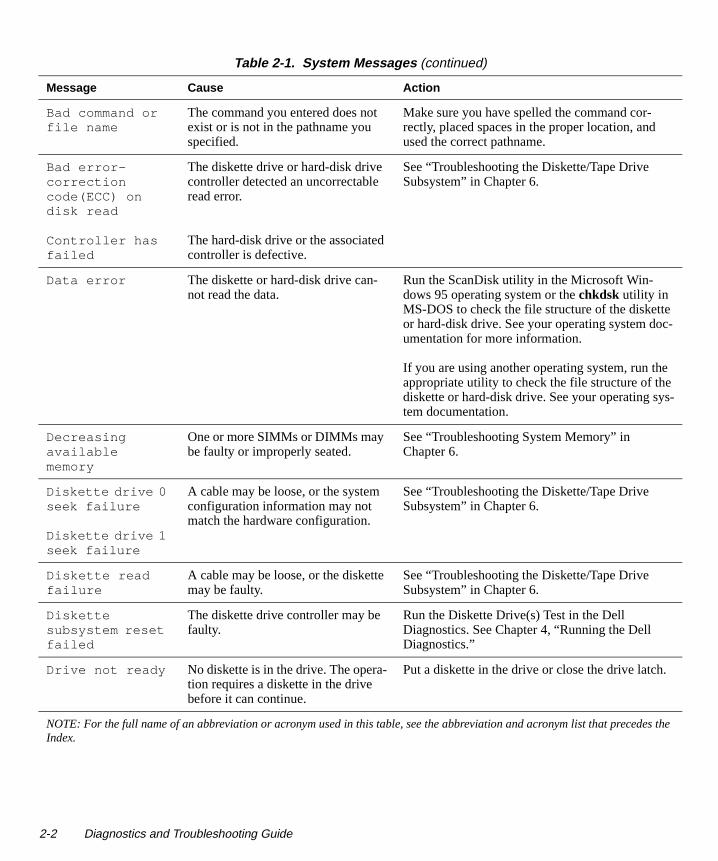
Bad command or file name
The command you entered does not exist or is not in the pathname you specified.
Make sure you have spelled the command cor-rectly, placed spaces in the proper location, and used the correct pathname.
Bad error-correction code(ECC) on disk read
Controller has failed
The diskette drive or hard-disk drive controller detected an uncorrectable read error.
The hard-disk drive or the associated controller is defective.
See “Troubleshooting the Diskette/Tape Drive Subsystem” in Chapter 6.
Data error The diskette or hard-disk drive can-not read the data.
Run the ScanDisk utility in the Microsoft Win-dows 95 operating system or the chkdsk utility in MS-DOS to check the file structure of the disketteor hard-disk drive. See your operating system documentation for more information.
If you are using another operating system, run theappropriate utility to check the file structure of thediskette or hard-disk drive. See your operating system documentation.
Decreasing available memory
One or more SIMMs or DIMMs may be faulty or improperly seated.
See “Troubleshooting System Memory” in Chapter 6.
Diskette drive 0 seek failure
Diskette drive 1 seek failure
A cable may be loose, or the system configuration information may not match the hardware configuration.
See “Troubleshooting the Diskette/Tape Drive Subsystem” in Chapter 6.
Diskette read failure
A cable may be loose, or the diskette may be faulty.
See “Troubleshooting the Diskette/Tape Drive Subsystem” in Chapter 6.
Diskette subsystem reset failed
The diskette drive controller may be faulty.
Run the Diskette Drive(s) Test in the Dell Diagnostics. See Chapter 4, “Running the Dell Diagnostics.”
Drive not ready No diskette is in the drive. The opera-tion requires a diskette in the drive before it can continue.
Put a diskette in the drive or close the drive latch.
Table 2-1. System Messages (continued)
Message Cause Action
NOTE: For the full name of an abbreviation or acronym used in this table, see the abbreviation and acronym list that precedhe Index.
2-2 Diagnostics and Troubleshooting Guide
-
.
-
es t
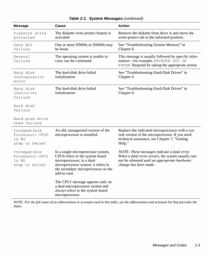
Diskette write protected
The diskette write-protect feature is activated.
Remove the diskette from drive A and move the write-protect tab to the unlocked position.
Gate A20 failure
One or more SIMMs or DIMMs may be loose.
See “Troubleshooting System Memory” in Chapter 6.
General failure
The operating system is unable to carry out the command.
This message is usually followed by specific information—for example, PRINTER OUT OF PAPER. Respond by taking the appropriate action
Hard disk configuration error
The hard-disk drive failed initialization.
See “Troubleshooting Hard-Disk Drives” in Chapter 6.
Hard disk controller failure
Hard disk failure
Hard-disk drive read failure
The hard-disk drive failed initialization.
See “Troubleshooting Hard-Disk Drives” in Chapter 6.
Incompatible Processor: CPU0 is B0 step or below!
Incompatible Processor: CPU1 is B0 step or below!
An old, unsupported version of the microprocessor is installed.
In a single-microprocessor system, CPU0 refers to the system board microprocessor; in a dual-microprocessor system, it refers to the secondary microprocessor on the add-in card.
The CPU1 message appears only on a dual-microprocessor system and always refers to the system board microprocessor.
Replace the indicated microprocessor with a cur-rent version of the microprocessor. If you need technical assistance, see Chapter 7, “Getting Help.”
NOTE: These messages indicate a fatal error. When a fatal error occurs, the system usually cannot be rebooted until an appropriate hardware change has been made.
Table 2-1. System Messages (continued)
Message Cause Action
NOTE: For the full name of an abbreviation or acronym used in this table, see the abbreviation and acronym list that precedhe Index.
Messages and Codes 2-3

.
es t
Incompatible Processors: Cache sizes different!
This message appears for a dual-processor system if both processors do not have the same-size level-2 cache.
Replace one of the microprocessors to make the level-2 cache sizes match. If you need technical assistance, see Chapter 7, “Getting Help.”
NOTE: This message indicates a fatal error. Whena fatal error occurs, the system usually cannot berebooted until an appropriate hardware change has been made.
Invalid configuration information - please run SETUP program
The system configuration informa-tion does not match the hardware configuration.
Enter the System Setup program and correct the system configuration information. See your systemdocumentation for instructions.
Keyboard clock line failure
Keyboard controller failure
Keyboard data line failure
Keyboard failure
Keyboard stuck key failure
A cable or connector may be loose, or the keyboard or keyboard/mouse controller may be faulty.
See “Troubleshooting the Keyboard” in Chapter 5
Memory address line failure at address , read value expecting value
One or more SIMMs may be faulty or improperly seated.
See “Troubleshooting System Memory” in Chapter 6.
Memory allocation error
The software you are attempting to run is conflicting with the operating system or another application pro-gram or utility.
Turn off the computer, wait 30 seconds, and then turn it on. Try to run the program again. If the problem persists, contact the software company.
Table 2-1. System Messages (continued)
Message Cause Action
NOTE: For the full name of an abbreviation or acronym used in this table, see the abbreviation and acronym list that precedhe Index.
2-4 Diagnostics and Troubleshooting Guide

es t
Memory data line failure at address , read value expecting value
Memory double word logic failure at address , read value expecting value
Memory odd/even logic failure at address , read value expecting value
Memory parity failure at address , read value expecting value
Memory write/read failure at address , read value expecting value
One or more SIMMs or DIMMs may be faulty or improperly seated.
See “Troubleshooting System Memory” in Chapter 6.
Memory size in CMOS invalid
The amount of memory recorded in the system configuration informa-tion does not match the memory installed in the computer.
Reboot the computer. If the error appears again, see Chapter 7, “Getting Help,” for instructions on obtaining technical assistance.
Memory tests terminated by keystroke
The memory test did not complete. Rerun the memory test.
Table 2-1. System Messages (continued)
Message Cause Action
NOTE: For the full name of an abbreviation or acronym used in this table, see the abbreviation and acronym list that precedhe Index.
Messages and Codes 2-5

m
-
m
r
g
es t
No boot device available
The computer cannot find the dis-kette or hard-disk drive.
Enter the System Setup program, check the systeconfiguration information for the diskette and hard-disk drive, and if necessary, correct the information. See your system documentation for instructions.
No boot sector on hard-disk drive
The system configuration informa-tion in the System Setup program may be incorrect, or the operating system may be corrupted.
Enter the System Setup program, check the systeconfiguration information for the hard-disk drive, and if necessary, correct the information. See yousystem documentation for instructions.
If the message persists, reinstall your operating system. See the documentation that came with your operating system.
No timer tick interrupt
A chip on the system board might be malfunctioning.
Run the System Set Test Group in the Dell Diagnostics. See Chapter 4, “Running the Dell Diagnostics.”
Non-system disk or disk error
The diskette in drive A or your hard-disk drive does not have a bootable operating system installed on it.
A nonbootable diskette is in drive A. Either replacethe diskette with one that has a bootable operatinsystem, or remove the diskette from drive A and restart the computer.
Not a boot diskette
There is no operating system on the diskette.
Boot the computer with a diskette that contains anoperating system.
Plug and Play Configuration Error
The system has encountered a prob-lem in trying to configure one or more expansion cards.
Run the ISA Configuration Utility to verify that all ISA expansion cards are configured correctly (seethe chapter titled “Using the ISA Configuration Utility” or the chapter titled “Using Configuration Software” in your system documentation. If run-ning the ISA Configuration Utility does not reveal the source of the problem, see “Troubleshooting Expansion Cards” in Chapter 6 of this guide.
Read fault
Requested sec-tor not found
The operating system cannot read from the diskette or hard-disk drive.
The system could not find a particu-lar sector on the disk, or the requested sector is defective.
See “Troubleshooting the Diskette/Tape Drive Subsystem” in Chapter 6.
Table 2-1. System Messages (continued)
Message Cause Action
NOTE: For the full name of an abbreviation or acronym used in this table, see the abbreviation and acronym list that precedhe Index.
2-6 Diagnostics and Troubleshooting Guide

If
e
es t
Reset failed The disk reset operation failed. See “Troubleshooting the Diskette/Tape Drive Subsystem” in Chapter 6.
Sector not found
The operating system is unable to locate a sector on the diskette or hard-disk drive.
See “Troubleshooting Hard-Disk Drives” or “Troubleshooting the Diskette/Tape Drive Sub-system” in Chapter 6, depending on what type of drive you are accessing.
Seek error The operating system is unable to find a specific track on the diskette or hard-disk drive.
If the error is on the diskette drive, try another diskette in the drive.
Shutdown failure
A chip on the system board might be malfunctioning.
Run the System Set Test Group in the Dell Diagnostics. See Chapter 4, “Running the Dell Diagnostics.”
Terminator/processor card cannot be installed!
Neither a terminator card nor a sec-ondary microprocessor card is installed in the secondary micropro-cessor card connector (2ND_CPU).
Make sure either a terminator card or a secondarymicroprocessor card is installed in the 2ND_CPUconnector. Reseat the card and start the system. errors persist, see Chapter 7, “Getting Help,” for instructions on obtaining technical assistance.
NOTE: This message indicates a fatal error. Whena fatal error occurs, the system usually cannot berebooted until an appropriate hardware change has been made.
Time-of-day clock stopped
The battery may be dead. Enter the System Setup program and correct thdate or time. See your system documentation for instructions.
If the problem persists, see “Troubleshooting the Battery” in Chapter 6.
Time-of-day not set
The time or date displayed in the sys-tem configuration information does not match the system clock.
Enter the System Setup program and correct the date or time. See your system documentation for instructions.
Timer chip counter 2 failed
A chip on the system board might be malfunctioning.
Run the System Set Test Group in the Dell Diagnostics. See Chapter 4, “Running the Dell Diagnostics.”
Table 2-1. System Messages (continued)
Message Cause Action
NOTE: For the full name of an abbreviation or acronym used in this table, see the abbreviation and acronym list that precedhe Index.
Messages and Codes 2-7

,
-
es t
Unexpected interrupt in protected mode
The keyboard controller may be mal-functioning, or one or more SIMMs or DIMMs may be loose.
Run the RAM Test Group and the Keyboard Con-troller Test in the Dell Diagnostics. See Chapter 4“Running the Dell Diagnostics.”
WARNING: Dell’s Disk Monitor-ing System has detected that drive [0/1] on the [primary/secondary] EIDE controller is operating outside of nor-mal specifica-tions. It is advisable to immediately back up your data and replace your hard-disk drive by calling your support desk or Dell Computer Corporation.
POST has queried the EIDE drive for status information. The drive has returned a parameter from the call that indicates it has detected possible error conditions for its operating specifications.
Once your computer finishes booting, immediatelyback up your data and replace your hard-disk drive. Restore the data to the replaced drive.
If a replacement drive is not immediately availableand the drive is not the only bootable drive, enter the System Setup program and change the appropriate drive setting to None. Remove the drive from the system. This should be done only after you have backed up the data.
Table 2-1. System Messages (continued)
Message Cause Action
NOTE: For the full name of an abbreviation or acronym used in this table, see the abbreviation and acronym list that precedhe Index.
2-8 Diagnostics and Troubleshooting Guide

es t
System Beep CodesWhen errors occur during a boot routine that cannot be reported on the monitor, your computer may emit a series of beeps that identify the problem. The beep code is a pattern of sounds: for example, one beep, followed by a second beep, and then a burst of three beeps (code 1-1-3) means that the computer was unable to read the data in nonvolatile random-access memory (NVRAM). This information is invaluable to the Dell support staff if you need to call for technical assistance.
Warning - Thermal Probes failed.
At system start-up, the BIOS has detected that one or both of the thermal probes in the computer are nonoperational.
You can continue to use the system, but be awarethat the temperature probe(s) are disabled and a processor overheat condition will not warn the Thermal Shutdown service to shut down the system.
NOTE: The Pentium® Pro microprocessor has a built-in thermocouple that halts microprocessor operation if the microprocessor exceeds its rated temperature.
To correct this problem, you must replace your system board. For technical assistance, see Chapter 7, “Getting Help.”
Warning - Temperature is too high.
At system start-up, the BIOS has detected that one or both microproces-sors are overheated. After displaying this message, the BIOS halts the pro-cesses and turns off the system.
Let the system cool down before attempting to restart it.
Write fault
Write fault on selected drive
The operating system cannot write to the diskette or hard-disk drive.
See “Troubleshooting the Diskette/Tape Drive Subsystem” in Chapter 6.
Table 2-1. System Messa ges (continued)
Message Cause Action
NOTE: For the full name of an abbreviation or acronym used in this table, see the abbreviation and acronym list that precedhe Index.
Messages and Codes 2-9

b-
4,
e
See
ee
e
un-
See
See
es t
When a beep code is emitted, write it down on a copy of the Diagnostics Checklist found in Chapter 7, “Getting Help,” and then look it up in Table 2-2. If you are unable to resolve the problem by looking up the meaning of the beep code, use the Dell Diagnostics to identify a more
serious cause. If you are still unable to resolve the prolem, see Chapter 7, “Getting Help,” for instructions on obtaining technical assistance.
Table 2-2. System Beep Codes
Code Cause Action
1-1-2 Microprocessor register failure
See Chapter 7, “Getting Help,” for instructions on obtaining technical assistance.
1-1-3 NVRAM Run the System Set Test Group in the Dell Diagnostics. See Chapter“Running the Dell Diagnostics.”
1-1-4 ROM BIOS checksum failure
Run the System Set Test Group in the Dell Diagnostics, if possible. SeChapter 4, “Running the Dell Diagnostics.”
1-2-1 Programmable interval timer Run the System Set Test Group in the Dell Diagnostics, if possible.Chapter 4, “Running the Dell Diagnostics.”
1-2-2 DMA initialization failure Run the System Set Test Group in the Dell Diagnostics, if possible. SChapter 4, “Running the Dell Diagnostics.”
1-2-3 DMA page register read/write failure
Run the System Set Test Group in the Dell Diagnostics, if possible. SeChapter 4, “Running the Dell Diagnostics.”
1-3 Video Memory Test failure Run the Video Test Group in the Dell Diagnostics. See Chapter 4, “Rning the Dell Diagnostics.”
1-3-1 through 2-4-4
SIMMs or DIMMs not being properly identified or used
See “Troubleshooting System Memory” in Chapter 7.
3-1-1 Slave DMA register failure Run the System Set Test Group in the Dell Diagnostics, if possible. Chapter 4, “Running the Dell Diagnostics.”
3-1-2 Master DMA register failure Run the System Set Test Group in the Dell Diagnostics, if possible. Chapter 4, “Running the Dell Diagnostics.”
3-1-3 Master interrupt mask register failure
Otherwise, see Chapter 7, “Getting Help,” for instructions on obtainingtechnical assistance.
3-1-4 Slave interrupt mask register failure
Otherwise, see Chapter 7, “Getting Help,” for instructions on obtainingtechnical assistance.
3-2-2 Interrupt vector loading failure
See Chapter 7, “Getting Help,” for instructions on obtaining technical assistance.
NOTE: For the full name of an abbreviation or acronym used in this table, see the abbreviation and acronym list that precedhe Index.
2-10 Diagnostics and Troubleshooting Guide
ee
ee
un-
un-
Run-
n-
g
l
l
n-
ing
ing
up .”
es t
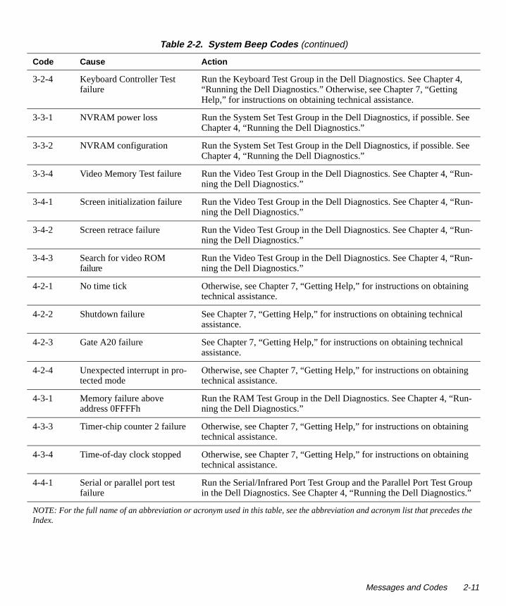
3-2-4 Keyboard Controller Test failure
Run the Keyboard Test Group in the Dell Diagnostics. See Chapter 4,“Running the Dell Diagnostics.” Otherwise, see Chapter 7, “Getting Help,” for instructions on obtaining technical assistance.
3-3-1 NVRAM power loss Run the System Set Test Group in the Dell Diagnostics, if possible. SChapter 4, “Running the Dell Diagnostics.”
3-3-2 NVRAM configuration Run the System Set Test Group in the Dell Diagnostics, if possible. SChapter 4, “Running the Dell Diagnostics.”
3-3-4 Video Memory Test failure Run the Video Test Group in the Dell Diagnostics. See Chapter 4, “Rning the Dell Diagnostics.”
3-4-1 Screen initialization failure Run the Video Test Group in the Dell Diagnostics. See Chapter 4, “Rning the Dell Diagnostics.”
3-4-2 Screen retrace failure Run the Video Test Group in the Dell Diagnostics. See Chapter 4, “ning the Dell Diagnostics.”
3-4-3 Search for video ROM failure
Run the Video Test Group in the Dell Diagnostics. See Chapter 4, “Runing the Dell Diagnostics.”
4-2-1 No time tick Otherwise, see Chapter 7, “Getting Help,” for instructions on obtainintechnical assistance.
4-2-2 Shutdown failure See Chapter 7, “Getting Help,” for instructions on obtaining technicaassistance.
4-2-3 Gate A20 failure See Chapter 7, “Getting Help,” for instructions on obtaining technicaassistance.
4-2-4 Unexpected interrupt in pro-tected mode
Otherwise, see Chapter 7, “Getting Help,” for instructions on obtainingtechnical assistance.
4-3-1 Memory failure above address 0FFFFh
Run the RAM Test Group in the Dell Diagnostics. See Chapter 4, “Runing the Dell Diagnostics.”
4-3-3 Timer-chip counter 2 failure Otherwise, see Chapter 7, “Getting Help,” for instructions on obtaintechnical assistance.
4-3-4 Time-of-day clock stopped Otherwise, see Chapter 7, “Getting Help,” for instructions on obtaintechnical assistance.
4-4-1 Serial or parallel port test failure
Run the Serial/Infrared Port Test Group and the Parallel Port Test Groin the Dell Diagnostics. See Chapter 4, “Running the Dell Diagnostics
Table 2-2. System Beep Codes (continued)
Code Cause Action
NOTE: For the full name of an abbreviation or acronym used in this table, see the abbreviation and acronym list that precedhe Index.
Messages and Codes 2-11

4,
ter 4,
er 4,
b-
r 4,
r 4,
r 4,
er 4,
r 4,
4,
es t
4-4-2 Failure to decompress code to shadowed memory.
Run the System Set Test Group in the Dell Diagnostics. See Chapter “Running the Dell Diagnostics.”
4-4-3 Math-coprocessor test failure Run the System Set Test Group in the Dell Diagnostics. See Chap“Running the Dell Diagnostics.”
4-4-4 Cache test failure Run the System Set Test Group in the Dell Diagnostics. See Chapt“Running the Dell Diagnostics.”
5-1-2 BIOS update error—no RAM in system
See “Troubleshooting System Memory” in Chapter 6.
5-1-3 BIOS update error—exter-nal video card detected
If a video expansion card is installed, disconnect the video expansioncard and connect the monitor to the built-in video subsystem. If the prolem is not resolved, see “Troubleshooting the Video Subsystem” in Chapter 6.
5-1-4 BIOS execution error Run the System Set Test Group in the Dell Diagnostics. See Chapte“Running the Dell Diagnostics.”
6-1-2 I/O controller failure Run the System Set Test Group in the Dell Diagnostics. See Chapte“Running the Dell Diagnostics.”
6-1-3 Keyboard controller failure Run the System Set Test Group in the Dell Diagnostics. See Chapte“Running the Dell Diagnostics.”
6-1-4 CMOS Register Test failure Run the System Set Test Group in the Dell Diagnostics. See Chapt“Running the Dell Diagnostics.”
6-2-1 BIOS shadowing failure Run the System Set Test Group in the Dell Diagnostics. See Chapte“Running the Dell Diagnostics.”
6-2-2 Pentium speed determina-tion failure
Run the System Set Test Group in the Dell Diagnostics. See Chapter “Running the Dell Diagnostics.”
6-2-3 No SIMM or DIMM installed
See “Troubleshooting System Memory” in Chapter 6.
Table 2-2. System Beep Codes (continued)
Code Cause Action
NOTE: For the full name of an abbreviation or acronym used in this table, see the abbreviation and acronym list that precedhe Index.
2-12 Diagnostics and Troubleshooting Guide

os-or
es-
Warning MessagesA warning message alerts you to a possible problem and asks you to do something before execution continues. For example, before you format a diskette, a message may warn you that you may lose all data on the diskette as a way to protect against inadvertently erasing or writing over the data. These warning messages usually interrupt the procedure and require you to respond by typing a y (yes) or n (no).
NOTE: Warning messages are generated by either your application programs or your operating system. See Chapter 3, “Finding Software Solutions,” and the docu-mentation that accompanied your operating system and application programs.
Diagnostics MessagesWhen you run a test group or subtest in the Dell Diagntics, an error message may result. These particular errmessages are not covered in this chapter. Record the msage on a copy of your Diagnostics Checklist found in Chapter 7, “Getting Help.” Also see Chapter 7 for instructions on obtaining technical assistance.
Messages and Codes 2-13

2-14 Diagnostics and Troubleshooting Guide

Chapter 3Findin g Software Solutions
-
s,
-
-
o - g
-
ed
m e
s-
Because most computers have several application programs installed in addition to the operating system, isolating a software problem can be confusing. Software errors can also appear to be hardware malfunctions at first. Software problems can result from the following circumstances:
• Improper installation or configuration of a program
• Input errors
• Device drivers that may conflict with certain appli-cation programs
• Memory conflicts resulting from the use of terminate-and-stay-resident (TSR) programs
• Interrupt conflicts between devices
You can confirm that a computer problem is caused by software by running the System Set Test Group as described in Chapter 4, “Running the Dell Diagnostics.” If all tests in the test group complete successfully, the error condition is most likely caused by software.
This chapter provides some general guidelines for ana-lyzing software problems. For detailed troubleshooting information on a particular program, see the documenta-tion that accompanied the software or consult the support service for the software.
Installin g and Confi gurin g SoftwareWhen you obtain software, check it for viruses with virus-scanning software before installing it on your com-puter’s hard-disk drive. Viruses, which are pieces of code that can replicate themselves, can quickly use all avail-able system memory, damage and/or destroy data stored on the hard-disk drive, and permanently affect the
performance of the programs they infect. Several commercial virus-scanning programs are available for purchase, and most bulletin board services (BBSs) archive freely distributed virus-scanning programs thatyou can download with a modem.
Before installing a program, read its documentation to learn how the program works, what hardware it requireand what its defaults are. A program usually includes installation instructions in its accompanying documentation and a software installation routine on its program diskettes.
The software installation routine assists you in transferring the appropriate program files to your computer’s hard-disk drive. Installation instructions may provide details about how to configure your operating system tsuccessfully run the program. Always read the installation instructions before running a program’s installationroutine. You may be instructed to modify some operatinsystem start-up files, such as config.sys and autoexec.bat, or the installation routine may modify start-up files automatically.
When you run the installation routine, be prepared to respond to prompts for information about how your computer’s operating system is configured, what type of computer you have, and what peripherals are connectto your computer.
Expanded and Extended MemoryDepending on which Dell computer you have, the systememory can be expanded by installing additional singlin-line memory modules (SIMMs) or dual in-line mem-ory modules (DIMMs) or by exchanging installed SIMMs or DIMMs for ones of larger capacity. If you operate your computer with MS-DOS, the operating sytem makes only 640 kilobytes (KB) (called conventional memory) of the first 1 megabyte (MB) of system memory
Finding Software Solutions 3-1

-2, that es-ng
are
t ’s
g
ots are
e
f .
s
ory e s he
available for use by application programs. Some pro-grams require more than 640 KB of memory and, therefore, cannot be run with conventional memory alone. Other programs run much faster when they have more than 1 MB of memory to use.
When you boot your computer, MS-DOS recognizes memory in excess of 1 MB as extended memory. Some, but not all, programs are able to use extended memory. For example, the Microsoft Windows 3.x operating sys-tem and Lotus® 1-2-3 take advantage of extended memory.
Other programs are able to use extended memory only if it is first converted into expanded memory by an expanded memory manager (EMM).
NOTE: Not all Dell computers have an EMM driver. See your system documentation to determine whether an EMM driver is provided with your system.
Under the following conditions, expanded memory can greatly enhance the system’s ability to use application programs that require more memory than is available in the conventional memory area:
• The application program is written for use with expanded memory.
• The memory has been properly allocated using the System Setup program. (See your system documen-tation for more information on the System Setup program.)
• The EMM driver is installed and properly initialized.
Improper use of an EMM can lead to conflicts between the expanded-memory operation and any installed expan-sion cards, which may be assigned memory areas that overlap memory areas that the EMM is using. For more information about these types of conflicts and how to avoid them, see “Checking for Memory Address Con-flicts” found later in this chapter.
Using SoftwareThe following subsections discuss errors that can occur as a result of software operation or configuration.
Error MessagesError messages can be produced by an application program, the operating system, or the computer. Chapter “Messages and Codes,” discusses the error messagesare generated by the system. If you receive an error msage that is not listed in Chapter 2, check your operatisystem or application program documentation.
Input ErrorsIf a specific key or set of keys is pressed at the wrong time, a program may give you unexpected results. See the documentation that came with your application programto make sure the values or characters you are enteringvalid.
Make sure the operating environment is set up to accommodate the programs you use. Keep in mind thawhenever you change the parameters of the computeroperating environment, you may affect the successful operation of your programs. Sometimes, after modifyinthe operating environment, you may need to reinstall aprogram that no longer runs properly.
Memory-Resident ProgramsThere are a variety of utilities and supplementary pro-grams that can be loaded either when the computer boor from an operating system prompt. These programs designed to stay resident in system memory and thus always be available for use. Because they remain in thcomputer’s memory, memory conflicts and errors can result when other programs require use of all or part othe memory already occupied by these TSR programs
Typically, your operating system’s start-up files (such aconfig.sys and autoexec.bat) contain commands to start TSR programs when you boot your system. If you sus-pect that one of these TSR programs is causing a memconflict, remove the commands that start them from thstart-up file. If the problem you were experiencing doenot recur, one of the TSR programs probably created tconflict. Add the TSR commands back into the start-upfiles one at a time until you identify which TSR programis creating the conflict.
3-2 Diagnostics and Troubleshooting Guide

-
Program ConflictsSome programs may leave portions of their setup infor-mation behind, even though you have exited from them. As a result, other programs cannot run. Rebooting your system can confirm whether or not these programs are the cause of the problem.
There are also programs that use specialized subroutines called device drivers that can also cause problems with your computer system. For example, a variation in the way the data is sent to the monitor may require a special screen driver program that expects a certain kind of video mode or monitor. In such cases, you may have to develop an alternative method of running that particular pro-gram—the creation of a boot file made especially for that program, for example. Call the support service for the software you are using to help you with this problem.
Checking for Memory Address Conflicts Memory address conflicts occur when two or more devices try to access the same address in the upper mem-ory block (UMB). For example, if a network expansion card and an expanded-memory page frame are assigned an overlapping block of addresses, a memory address conflict arises. As a result, when you try to log into the network, the operation fails.
To resolve this type of conflict, you can change the address of one of the devices. For example, in the case of the network expansion card and expanded-memory page-frame address conflict, you can move the network card to an address block in the range of CC000h through D0000h. To reassign the expansion card’s address block, refer to the documentation for the card.
Avoiding Interrupt Assignment ConflictsProblems can arise if two devices attempt to use the same interrupt request (IRQ) line. To avoid this type of con-flict, check the documentation for the default IRQ line setting for each installed expansion card. Then consult Table 3-1 to configure the card for one of the available IRQ lines.
NOTE: Table 3-1 lists default IRQ settings. In systems with Plug and Play capabilities, the default settings can be modified. If you are installing a Plug and Play card in a Plug and Play system, the system will automatically
select an open IRQ line if any are available. If you are installing a non-Plug and Play or legacy card, run the ISA Configuration Utility provided with your system to determine the current IRQ settings and to find an available IRQ line. For instructions, see the ISA Configuration Utility chapter in your system documentation.
Table 3-1. Default IRQ Line Assignments
IRQ Line Used/Available
IRQ0 Used by the system timer
IRQ1 Used by the keyboard to signal that theoutput buffer is full
IRQ2 Used by interrupt controller 1 to enableIRQ8 through IRQ15
IRQ3 Used by serial port 2
IRQ4 Used by serial port 1
IRQ5 Available
IRQ6 Used by the diskette/tape drive controller
IRQ7 Used by the parallel port
IRQ8 Used by the RTC
IRQ9 Used by the VGA interface (optional)
IRQ10 Available
IRQ11 Available
IRQ12 Used by the mouse port
IRQ13 Used by the math coprocessor (if applicable)
IRQ14 Used by the primary IDE controller
IRQ15 Used by the secondary IDE controller
NOTE: For the full name of an abbreviation or acronym usedin this table, see the abbreviation and acronym list that pre-cedes the Index.
Finding Software Solutions 3-3

3-4 Diagnostics and Troubleshooting Guide

Chapter 4Runnin g the Dell Dia gnostics
s
ps
a the ,
ed d
ter.
Unlike many diagnostic programs, the Dell Diagnos-tics helps you check your computer’s hardware without any additional equipment and without destroying any data. By using the diagnostics, you can have confidence in your computer system’s operation. And if you find a problem you cannot solve by yourself, the diagnostic tests can provide you with important information you will need when talking to Dell’s service and support personnel.
Features of the Dell Dia gnosticsThe Dell Diagnostics provides a series of menus and options from which you choose particular test groups or subtests. You can also control the sequence in which the tests are run. The diagnostic test groups or subtests also have these helpful features:
• Options that let you run tests individually or collectively
• An option that allows you to choose the number of times a test group or subtest is repeated
• The ability to display or print out test results, or to save them in a file
• Options to temporarily suspend testing if an error is detected, or to terminate testing when an adjustable error limit is reached
• A menu category called About that briefly describeeach test and its parameters
• Status messages that inform you whether test grouor subtests were completed successfully
• Error messages that appear if any problems are detected
When to Use the Dell DiagnosticsWhenever a major component or device in your com-puter system does not function properly, you may havecomponent failure. As long as the microprocessor and input and output components of your computer system(the monitor, keyboard, and diskette drive) are workingyou can use the Dell Diagnostics. If you are experiencwith computers and know what component(s) you neeto test, simply select the appropriate diagnostic test group(s) or subtest(s). If you are unsure about how to begin diagnosing a problem, read the rest of this chap
Before You Start Testin gFollow these steps to create a master and/or working copy of the Dell Diagnostics Diskette.
1. If you received a Dell Diagnostics Diskette with your Dell system, go to step 4.
CAUTION: Use the Dell Diagnostics to test onlyyour Dell computer system. Using this programwith other computers may cause incorrect com-puter responses or result in error messages.
Running the Dell Diagnostics 4-1

d
y t
g-
g-
k on ob-ct
to
2. If you did not receive a Dell Diagnostics Diskette, a diskette image has been installed on your computer’s hard-disk drive so that you can make your own copy of the diskette.
If Dell installed the Microsoft Windows 3.x or Windows 95 operating system on your computer’s hard-disk drive, see the online help in Dell’s Pro-gram Diskette Maker utility, which is available in the Dell Accessories group or folder, for instructions on making a program diskette set from the diskette image.
If Dell installed MS-DOS, but not Windows, on your computer’s hard-disk drive, see the Dell Menu, which appears when you first turn on your system, for instructions on making a program diskette set from the diskette image.
3. Using a felt-tip pen, write “Dell Diagnostics Dis-kette” on the diskette label.
4. Make a working copy of the Dell Diagnostics Dis-kette on a blank diskette.
Refer to your operating system’s documentation for information on how to duplicate diskettes. Put the original diskette away for safekeeping.
5. Turn on your printer if one is attached, and make sure it is online.
6. Enter the System Setup program, confirm your computer’s system configuration information, and enable all its components and devices, such as ports.
For instructions on entering and using the System Setup program, see your system documentation.
Starting the Dell DiagnosticsAfter you complete the preliminary instructions specifiein the previous section, follow these steps to start the diagnostics:
1. Turn off the computer.
2. Place your diagnostics diskette in drive A, and boot the system.
NOTE: Before you read the rest of this chapter, you mawant to start the Dell Diagnostics so that you can see ion the screen of your monitor.
When you start the diagnostics, the Dell logo screen appears, followed by a message telling you that the dianostics is loading.
After the diagnostics loads, the Diagnostics Menu appears. The menu allows you to run all or specific dianostic tests or to exit to the MS-DOS prompt.
For a quick check of your system, select the Run QuicTests option. This option runs only the subtests that donot require user interaction and that do not take a longtime to run. Dell recommends that you choose this optifirst to increase the odds of tracing the source of the prlem quickly. For a thorough check of your system, selethe Run All Tests option. To check a particular area of your system, select the Run Specific Tests option.
To select an option from this menu, highlight the optionand press <Enter>, or press the key that corresponds the highlighted letter in the option you choose.
4-2 Diagnostics and Troubleshooting Guide

o
u-
-
n
t n
Figure 4-1. Diagnostics Menu
How to Use the Dell DiagnosticsWhen you select Run Specific Tests from the Diagnostics Menu, the main screen of the diagnostics appears (see Figure 4-2). The main screen lists the diagnostic test groups, gives information about the configuration of your computer system, and allows you to select categories from a menu. From this screen, you can enter two other types of screens.
Information on the main screen of the diagnostics is pre-sented in the following five areas:
• Two lines at the top of the screen identify the version number of the Dell Diagnostics.
• On the left side of the screen, the Available Test Group area lists the diagnostic test groups in the order they will run if you select All from the Run menu category. Press the up- or down-arrow key thighlight a test group.
• On the right side of the screen, the System Configration area lists the computer’s currently detected hardware and some of the relevant settings.
• The lower-right side of the screen displays information about your integrated drive electronics (IDE) hard-disk and CD-ROM drive(s).
• Two lines at the bottom of the screen make up themenu area. The first line lists the categories you caselect; press the left- or right-arrow key to highligha menu category. The second line gives informatioabout the category currently highlighted.
Dell Computer Corporation
Dell System Diagnostics Version X.XX
Run All TestsRUn Quick TestsRuN Specific TestsExit To MS-DOS
Diagnostics Menu
Running the Dell Diagnostics 4-3

es
u
at
Figure 4-2. Dell Diagnostics Screen
Confirming the System Configu-ration InformationWhen you boot your system from your diagnostics dis-kette, the diagnostics checks your system configuration information and displays it in the System Configuration area on the main screen.
The following sources supply this configuration informa-tion for the diagnostics:
• The system configuration information settings (stored in nonvolatile random-access memory [NVRAM]) that you selected while using the System Setup program
• Identification tests of the microprocessor, the videocontroller, the keyboard controller, and other key components
• Basic input/output system (BIOS) configuration information temporarily saved in RAM
Do not be concerned if the System Configuration areadoes not list the names of all the components or devicyou know are part of your computer system. For example, you may not see a printer listed, although yoknow one is attached to your computer. Instead, the printer is listed as a parallel port. The computer recog-nizes the parallel port as LPT1, which is an address thtells the computer where to send outgoing information and where to look for incoming information. Because
RAM System SetVideoKeyboardMouseDiskette DrivesHard-Disk Drives (Non-SCSI)IDE CD ROM DrivesSerial/Infrared PortsParallel PortsSCSI DevicesNetwork InterfaceAudioOther
NOTE: The options displayed on your screen should reflect the hardware configuration of your computer system.
Dell Computer CorporationDell System Diagnostics Version X.XX
Memory 4 MBSecondary Cache 128 KBProcessor(s) PentiumVideo SVGA,1024KKeyboard 101 KeyMouse PS/2 2-buttonDiskette Drive(s) A:1.4MBIDE(0)524MB, 1016 Cyl, 16 Hd, 63 SecIDE(2) CDROM: NEC CD-ROM DRIVE:260Serial/IR Port(s) 2Parallel Port(s) 1Modems NoneSCSI Devices 2Network Interface NoneSerial/IR Ports IntegratedAudio NoneEmbedded Server Management
System ConfigurationAvailable Test Groups
Main Menu: Run se Lect Subtest Options Test_limits About Key_help Quit Display the Run Menu. Press Q to Quit
4-4 Diagnostics and Troubleshooting Guide

s that ct
as
.
or
ally s
en
p
e
up ct
.
e n
s as
your printer is a parallel communications device, the computer recognizes the printer by its LPT1 address and identifies it as a parallel port.
How to Use the MenuOne of the menu categories is already highlighted. You can move the highlight from one category to another by pressing the left- or right-arrow key. As you move from one menu category to another, a brief explanation of the currently highlighted category appears on the bottom line of the screen.
If you want more information about a test group or sub-test, move the highlight to the About category and press <Enter>. After reading the information, press the <Esc> key to return to the previous screen.
Main Menu CategoriesEight categories are listed in the Main menu of the diag-nostics main screen: Run, Select, Subtest, Options, Test Limits, About, Key-Help, and Quit.
NOTE: Before running any test groups or subtests (by selecting Run), you should consider setting global parameters within the Options category. They offer you greater control over how the test groups or subtests are run and how their results are reported.
There are two ways to select a menu category:
• Look on the screen to see which letter in the category is capitalized, and type that letter (for example, type r to select the Run category).
• Move the highlight to the category you wish to select by pressing the left- or right-arrow key, and then press <Enter>.
Whenever one of the eight categories is selected, addi-tional choices become available.
The following subsections explain the menu categories as listed from left to right in the Main menu.
RunRun displays five categories: One, Selected, All, Key-Help, and Quit Menu. If you select One, all the subtestwithin the highlighted test group are run. If you chooseSelected, only the selected test groups or the subtestsyou selected within the test groups are run. If you seleAll, all of the subtests in all of the test groups are run. (The test groups or subtests are run in the same orderthey are listed.)
The Key-Help category displays a list of key controls available for the particular category you have chosen.
The Quit Menu category returns you to the Main menu
SelectSelect allows you to select individual test groups to tailthe testing process to your particular needs. You can choose one or more test groups and run them sequentior individually. When you choose Select, five categorieare displayed: All, One, Clear All, Key-Help, and Quit Menu.
To select all the test groups, press the <Enter> key whAll is highlighted in the Select menu.
To select an individual test group, highlight the test grouand press the <Spacebar> or highlight One and press <Enter>. Press the up- or down-arrow key to change thhighlighted test group.
To reverse a test group selection, highlight the test groand press the <Spacebar>. To clear all selections, seleClear All.
The Key-Help category displays a list of key controls available for the particular category you have chosen. The Quit Menu category returns you to the Main menu
SubtestMost of the test groups consist of several subtests. Usthe Subtest category to select individual subtests withithe test group(s).
When you select Subtest, many of the same categoriethose on the Main menu are displayed: Run, Select, Options, Test Limits, About, Key-Help, and Quit Menu.Each of these categories is explained in the following subsections.
Running the Dell Diagnostics 4-5
-
ou
l -
or
run e
rs nt
e.
Run Under SubtestRun in the Subtest menu displays five categories: One, Selected, All, Key-Help, and Quit Menu. If you select One, only the highlighted subtest is run. If you select Selected, only the selected subtests are run. If you select All, all of the subtests listed on the screen are run. (The subtests are run in the same order as they are listed.)
The Key-Help category displays a list of key controls available. The Quit Menu category returns you to the pre-vious menu.
Select Under SubtestSelect in the Subtest menu allows you to select individual subtests to tailor the testing process to your particular needs. You can choose one or more subtests from the list. When you choose Select, five categories are displayed: All, One, Clear All, Key-Help, and Quit Menu.
To select all the subtests, press the <Enter> key when All is highlighted in the Select menu. To select an individual subtest, highlight the subtest and press the <Spacebar> or highlight One and press <Enter>. Press the up- or down-arrow key to highlight a subtest to be selected.
To reverse a subtest selection, highlight the subtest and press the <Spacebar>. To clear all selections, select Clear All.
The Key-Help category displays a list of key controls available. The Quit Menu category returns you to the pre-vious menu.
Options Under SubtestThe Options category in the Subtest menu functions the same way as the Options category in the Main menu. For information on this category, see “Options” found later in this chapter.
Test Limits Under SubtestThe Test Limits category in the Subtest menu functions the same way as the Test Limits category in the Main menu. For information on this category, see “Test Limits” found later in this chapter.
About Under SubtestThe About category in the Subtest menu displays information about the highlighted subtest.
Key-Help Under SubtestThe Key-Help category in the Subtest menu displays alist of key controls available.
Quit Menu Under SubtestThe Quit Menu category in the Subtest menu returns yto the Main menu.
OptionsTable 4-1 lists all of the possible values for each globaparameter of Options. A brief description of each parameter follows the table. To change Options parameters, press the <Spacebar>, the left- and right- arrow keys, the plus (+) and minus (-) keys.
Number of Times to Repeat Test(s) This parameter specifies the number of times the tests when you select Run. To change the default, type in thdesired value. If you type 0 (zero), the tests will run indefinitely.
Maximum Errors AllowedThis parameter specifies the maximum number of errothat can occur before testing is stopped. The error coubegins from zero each time you run a subtest or test group individually or each time you select All to run all of them. To change the default, type in the desired valu
4-6 Diagnostics and Troubleshooting Guide

en. o
a
n
n
the
he er e
s-
If you type 0 (zero), you are specifying that there be no limit on the number of errors that can occur—testing will not be stopped, regardless of the number of errors.
Pause for User ResponseIf this parameter value is set to Yes, the diagnostics pauses when one of the following occurs:
• Your interaction is needed to verify the Video Test Group screens or the Keyboard Test Group key func-tions or other types of interaction such as inserting a diskette.
• The maximum error limit is reached.
If the Pause parameter is set to No, the diagnostics ignores some subtests that require your interaction; cer-tain subtests can run only if this option is set to Yes because they require user interaction. Use the Pause parameter in situations where you may want to prevent subtests that require user interaction from running—such as when you run the diagnostics overnight.
Output Device for Status Messages Ordinarily, all status messages appear only on the screThis parameter allows you to direct status messages teither a printer or a file, in addition to the screen. If youchoose the File option, status messages are written tofile named result. This file is automatically created on adiskette that you insert into drive A when prompted. If you are running the diagnostics from a utility partition oyour hard-disk drive, the result file is created on the hard-disk drive. If the result file already exists, new sta-tus messages are added to it.
The result file is an ordinary American Standard Code for Information Interchange (ASCII) text file that you can open in any text viewer or word processor. You caalso access the result file with the MS-DOS type com-mand as follows:
Table 4-1. Option Parameters
Option Limit Possible Values
Number of Times to Repeat Test(s) 0001 through 9999, or 0000, which loops indefinitely until you press<Ctrl> and <Break> keys. The default is 1.
Maximum Errors Allowed 0000 through 9999, where 0000 means that there is no error limit.The default is 1.
Pause For User Response Yes, NoAllows you to decide whether tests will wait for user input.The default is Yes to wait for user input.
Output Device for Status Messages Display, Printer, FileIf you have a printer attached to your computer, you can use it to print tstatus messages, if any, that are generated when a test runs. (The printmust be turned on and in the online mode to print.) If you select File, thmessages are printed to a file named result on a diskette that you insert into drive A when prompted. If you are running the diagnostics from a utility partition on your hard-disk drive, the result file is created on the hard-disk drive. The default is Display.
Output Device for Error Messages Display, Printer, FileThis parameter has the same effect as the Output Device for Status Mesages parameter, except that it pertains only to error messages.The default is Display.
Running the Dell Diagnostics 4-7

rea n>
r ith
t its g g he
he
ou
e
s .
1. Select Quit to exit the diagnostics and return to the operating system prompt.
2. At the operating system prompt, type the appro-priate command and press <Enter>:
type result
The contents of the file appear on the screen.
After running particular diagnostic tests and viewing the status messages generated by the tests in the result file, you can erase the contents of the file so that it is clear for the next set of messages generated. Otherwise, the next messages are added at the end of the previous ones in the file.
Output Device for Error Messages Ordinarily, all error messages appear only on the screen. This parameter allows you to direct error messages to either a printer or a file, in addition to the screen. If you choose the File option, error messages are written to the result file used for status messages. This file is automati-cally created on a diskette that you insert into drive A when prompted. If you are running the diagnostics from a utility partition on your hard-disk drive, the result file is created on the hard-disk drive. If the result file already exists, new error messages are added to it.
The result file is an ordinary ASCII text file. You can access and review the result file as described in the pre-vious subsection, “Output Device for Status Messages.”
After running particular diagnostic tests and viewing the error messages generated by the tests in the result file, you can erase the contents of the file so that it is clear for the next set of messages generated. Otherwise, the next messages are added at the end of the previous ones in the file.
Test LimitsNOTE: The Dell Diagnostics sets default limits on all tests. The only reason to change the default would be to limit the amount of testing done.
The RAM Test Group, the Video Test Group, the Diskette Drives Test Group, the Hard-Disk Drives (Non-SCSI) Test Group, the Serial/Infrared Ports Test Group, the Par-allel Ports Test Group, and the SCSI Devices Test Group allow you to designate limits. Whether you select Test Limits for a highlighted test group (from the Main menu)
or a subtest (from the Subtest menu), you set the limitsfor all the subtests in that test group. When you select Test Limits, a new screen appears and the Key-Help alists keys to use with the new screen. Press <Page Dowto select the next menu or submenu. Press <Esc> to return to the main Test Limits window.
How you change a value for the limits of a test group osubtest depends on the type of parameter associated wit. Different keys are used to change values for differentypes of parameters. For example, memory address limspecified for the RAM Test Group are changed by typinin numbers over the digits of a given limit or by pressinthe plus (+) or minus (-) keys to increase or decrease tgiven limit. In contrast, to set limits for the Serial/Infrared Ports Test Group, you use the <Spacebar> totoggle between Yes and No.
After you are satisfied with the limits, return to the DellDiagnostics main screen by pressing the <Esc> key. Tvalues you selected under Test Limits remain in effect during all the test groups or subtests you run, unless ychange them. However, the values are reset to their defaults when you restart the diagnostics.
AboutAbout in the Main menu lists all of the subtests for the selected test group and displays information about thesubtest that is highlighted.
Key-HelpKey-Help always displays a list of key controls availablfor the particular category you have selected.
Quit Selecting Quit from the Main menu exits the diagnosticand returns you to your operating system environment
After you return to the operating system environment, remove your diagnostics diskette from drive A and reboot the computer.
CAUTION: It is important that you quit the diag-nostics correctly because the program writes datato the computer’s memory that can cause prob-lems unless properly cleared.
4-8 Diagnostics and Troubleshooting Guide

n e
,
nd
Tests in the Dell DiagnosticsTo troubleshoot components or devices, run the appropri-ate test (test group or subtest) in the diagnostics on your diagnostics diskette. The diagnostics exercises the func-tional components and devices of your computer system more vigorously and thoroughly than they are exercised during normal operation. The diagnostics is organized by components into test groups and subtests within each test group. Each subtest is designed to detect any errors that
may interfere with the normal operation of a specific device of the computer.
NOTE: Some subtests requiring hardware not listed in the System Configuration area of the diagnostics screeappear to run, but they conclude with a status messagstating Component not present (or disabled).
Table 4-2 lists the diagnostic test groups, their subtestsand comments concerning their use.
Table 4-2. Dell Dia gnostics Tests
Test Groups Subtests Description
RAM Quick Memory TestComprehensive Memory TestSecondary Cache Memory Test
Tests the RAM and cache. (Some computers include expanded or extended memory; all memory is tested.)
System Set CMOS Confidence TestCMEM Confidence TestDMA Controller TestReal-Time Clock TestSystem Timers TestInterrupt Controller TestReset Button TestSystem Speaker Test
Coprocessor Calculation TestCoprocessor Error Exception Test
PC Card Controller Test
Thermal Control Test
Multiprocessor Test
USB Register Test
USB Memory Structure Test
Tests the system board’s support chips, DMA con-troller, computer timer, NVRAM, speaker controller, cache, and EISA configuration RAM chip, as appropriate.
Tests the math coprocessor that is internal to the microprocessor.
Tests the PC Card controller on the system board.
Checks the functionality of the thermal-monitoring and microprocessor speed-switching device on the system board.
For systems with multiprocessors, confirms that the secondary microprocessor is operational.
Checks the onboard registers of the USB interface. This subtest does not test USB peripherals.
Monitors the ability of a USB controller to process a simple set of memory-resident instructions.
NOTES: Not all of these tests appear for each system.
For the full name of an abbreviation or acronym used in this table, see the abbreviation and acronym list that precedes the Iex.
Running the Dell Diagnostics 4-9

nd
Video Video Memory TestVideo Hardware TestText Mode Character TestText Mode Color TestText Mode Pages TestGraphics Mode TestColor Palettes TestSolid Colors Test
Tests the video subsystem and monitor by checking various aspects of video output.
Keyboard Keyboard Controller TestKeyboard Key Sequence TestKeyboard Interactive TestStuck Key TestExternal Key Pad Test
Tests the keyboard by checking the keyboard controller and by finding keys that stick or respond incorrectly.
Mouse Mouse Tests the electronic pointing device (bus mouse, serial mouse, trackball, or PS/2 mouse).
Diskette Drives Change Line TestSeek TestRead TestWrite Test
Tests a drive that uses removable diskettes (3.5-inch or 5.25-inch). Also tests the associated interface.
Hard-Disk Drives (Non-SCSI)
Disk Controller TestForced Error-Correction-Code TestSeek TestRead TestWrite Test
Tests drives that use fixed, internal disks. Also tests the associated interface.
IDE CD ROM Drives
Drive Controller TestSeek TestRead TestAudio Output TestEject Removable Media
Tests an IDE drive that uses removable CD media. Also tests the associated interface.
Serial/Infrared Ports
Serial/Infrared Baud Rate TestSerial/Infrared Interrupt TestSerial/Infrared Internal Trans-mission TestSerial External Transmission Test
Tests the components through which peripherals that use the serial or infrared ports, such as printers and communications devices, send and receive data.
Table 4-2. Dell Diagnostics Tests (continued)
Test Groups Subtests Description
NOTES: Not all of these tests appear for each system.
For the full name of an abbreviation or acronym used in this table, see the abbreviation and acronym list that precedes the Iex.
4-10 Diagnostics and Troubleshooting Guide

nd
Parallel Ports Parallel Internal TestParallel External Loopback TestParallel External Interrupt TestParallel Printer Pattern Test
Tests the components through which peripherals that use the parallel port, such as printers and communi-cations devices, send and receive data.
SCSI Devices Internal DiagnosticSeek TestRead TestWrite TestAudio Output TestEject Removable MediaDisplay Information
Tests any installed SCSI host adapters and all the SCSI devices attached to them. Also can be used to remove CDs and tape cartridges from SCSI devices and to display information about the types of SCSI devices installed and the resources allocated to them.
Network Interface Registers TestInternal Loopback TestExternal Loopback TestShared RAM TestDisplay Information
Tests the read and write access capability to the NIC registers. Also tests the ability of the NIC to transmit and receive data.
Audio Software Reset TestCompatibility ID TestInterrupt TestDMA TestFIFO RAM TestInitial Reset Status TestInternal Register TestDual Channel Test
FM Sound Playback TestAnalog Sound Playback TestRecord and Playback Test
Tests the operation of the audio chip set.
Tests the record and playback abilityof the internal microphone and speakers.
Table 4-2. Dell Diagnostics Tests (continued)
Test Groups Subtests Description
NOTES: Not all of these tests appear for each system.
For the full name of an abbreviation or acronym used in this table, see the abbreviation and acronym list that precedes the Iex.
Running the Dell Diagnostics 4-11

ay
g
e
y
ce
d
p
s.
Error MessagesWhen you run a test group or subtest in the Dell Diagnos-tics, error messages may result. These particular error messages are not covered in this chapter because the errors that generate these messages can be resolved only with Dell technical assistance. Record the messages on a copy of the Diagnostics Checklist found in Chapter 7, “Getting Help.” For instructions on obtaining technical assistance and for informing the support technician of these messages, also see Chapter 7.
RAM Test GroupThe RAM Test Group subtests check all the directly addressable RAM.
The RAM Test program has parameters for the subtests that you can set: Test Limits and Options.
SubtestsThree subtests are available for RAM: the Quick Mem-ory Test, the Comprehensive Memory Test, and the Secondary Cache Memory Test. The Quick Memory Test performs an address check to determine whether the computer is properly setting and clearing individual bits in RAM and whether the RAM read and write operations are affecting more than one memory address location at one time. This subtest checks all available RAM. The Comprehensive Memory Test also performs an address check, as well as the following:
• Data pattern checks, to look for RAM bits that are stuck high or low, short-circuited data lines, and some data pattern problems that are internal to the memory chips
• A parity check that verifies the ability of the memory subsystem to detect errors
• A refresh check, to verify that the dynamic RAM (DRAM) is being recharged properly
The Secondary Cache Memory Test confirms the func-tionality of the computer’s cache controller chip and the cache memory.
Why Run a RAM Test?Faulty memory can cause a variety of problems that mnot, at first glance, appear to be happening in RAM. If your computer is displaying one or more of the followinsymptoms, run the subtests in the RAM Test Group to verify that the memory is not at fault:
• A program is not running as usual, or a proven piecof software appears to malfunction and you confirm that the software itself is not at fault. (You can confirm that the software is functioning properlby moving it to another computer and running it there.)
• Your computer periodically locks up (becomes unus-able and must be rebooted), especially at differentplaces and times in different programs.
• You get parity errors (any error message that con-tains the word parity) at any time during operation. These errors are usually accompanied by a referento an address—the location of the portion of mem-ory where the error occurred—which you should record on a copy of the Diagnostics Checklist founin Chapter 7, “Getting Help.”
System Set Test GroupThe subtests in the System Set Test Group check the computer’s basic system board components and verifytheir related functions.
SubtestsThe subtests that constitute the System Set Test Grouand the computer functions they confirm follow:
• CMOS Confidence Test
Checks the NVRAM for accessibility and reliabilityof data storage by performing a data pattern checkand verifying the uniqueness of memory addresse
• CMEM Confidence Test
Verifies the accessibility and reliability of the 8 kilobytes (KB) of RAM on the Extended Industry-Standard Architecture (EISA) Configura-tion RAM chip, which stores the EISA hardware configuration information. On systems without flash
4-12 Diagnostics and Troubleshooting Guide

e
l B
a
t b-t -
er-ker,
h ys-
ce
.)
r
-
-
RAM, performs a data pattern and address unique-ness test.
NOTE: This test applies only to systems with an EISA bus.
• DMA Controller Test
Tests the direct memory access (DMA) controller and verifies the correct operation of its page and channel registers by writing patterns to the registers.
• Real-Time Clock Test
Confirms the functionality and accuracy of the com-puter’s real-time clock (RTC).
• System Timers Test
Checks the timers used by the microprocessor for event counting, frequency generation, and other functions. Only the functions that can be activated by software are tested.
• Interrupt Controller Test
Generates an interrupt on each interrupt request (IRQ) line to verify that devices using that line can communicate with the microprocessor and that the interrupt controllers send the correct memory addresses to the microprocessor.
• Reset Button Test
Confirms that the reset button works.
• System Speaker Test
Checks the functionality of the speaker by generat-ing eight tones.
• Coprocessor Calculation Test
Checks the use of different types of numbers and the math coprocessor’s ability to calculate correctly.
• Coprocessor Error Exception Test
Verifies the math coprocessor’s ability to handle errors and to send IRQs to the microprocessor.
• PC Card Controller Test
Tests the functionality of the PC Card controller on the system board.
• Thermal Control Test
Checks the functionality of the thermal-monitoring and microprocessor speed-switching device on thesystem board.
• Multiprocessor Test
For systems with multiprocessors, confirms that thsecondary microprocessor is operational.
• USB Register Test
Checks the onboard registers of the universal seriabus (USB) interface. This subtest does not test USperipherals.
• USB Memory Structure Test
Monitors the ability of a USB controller to process simple set of memory-resident instructions.
Why Run a System Set Test?The System Set subtests double-check many system board components, such as the computer’s input/outpu(I/O) circuitry, that are tested by other test groups or sutests in the diagnostics. You should run the System SeTest Group if you are having a problem and cannot isolate the failure or malfunction to a particular system board component.
The System Set Test Group also verifies the proper opation of other computer components, such as the speathat are not tested elsewhere in the Dell Diagnostics.
The following symptoms usually suggest a problem wita component or subassembly that warrants running a Stem Set subtest:
• A program is not running as usual, or a proven pieof software appears to malfunction and you confirmthat the software itself is not at fault. (You can con-firm that the software is functioning properly by moving it to another computer and running it there
• An option card you previously accessed can no longer be accessed.
• You get parity errors or page fault failures (any erromessage that contains the word parity or page fault) at any time during operation. These errors are usually accompanied by a reference to an address, which you should record on a copy of the Diagnostics Checklist found in Chapter 7, “Getting Help.”
Running the Dell Diagnostics 4-13

ta
or
e
ta
f
the
s al
the
t in
• Correcting errors in the system configuration infor-mation in the System Setup program does not resolve a problem.
• The computer’s clock/calendar stops.
• The speaker no longer functions. The problem could be a failure of the system timers as well as a failure of the speaker itself. Run the System Timers Test, followed by the System Speaker Test.
• If a peripheral device appears to malfunction, run the Interrupt Controllers Test.
• A spreadsheet program or other type of mathemati-cal application runs abnormally slow, generates error messages concerning calculations or operations, runs incorrectly, or generates incorrect results, or a proven piece of the program appears to malfunction and you confirm that the software itself is not at fault. (You can confirm that the software is not at fault by moving the program to another computer and running it there.)
• The computer periodically locks up, especially at different places and times in different programs.
• The computer halts in the middle of performing cal-culations or complex mathematical operations.
Video Test GroupThe subtests in the Video Test Group verify the proper operation of the video controller and the video control circuitry installed in your computer. These subtests check for the correct operation of the readable registers in the video circuitry and the controller. They write, read, and verify data patterns in the cursor registers of the control-ler. The Video Test Group also tests all the video memory and provides additional subtests to test the color features of a color monitor.
SubtestsThe eight subtests in the Video Test Group confirm the following video functions:
• Video Memory Test
Checks the read/write capability of video memory in various video modes.
• Video Hardware Test
Checks the cursor registers and the horizontal andvertical retrace bit registers in the video controller.
• Text Mode Character Test
Checks the video subsystem’s ability to present dain text modes.
• Text Mode Color Test
Checks the video subsystem’s ability to present colin text modes.
• Text Mode Pages Test
Checks the video subsystem’s ability to map and present all available video pages on the screen, onpage at a time.
• Graphics Mode Test
Checks the video subsystem’s ability to present daand color in graphics modes.
• Color Palettes Test
Checks the video subsystem’s ability to display all othe available colors.
• Solid Colors Test
Checks the video subsystem’s ability to show screens full of solid colors. Allows you to check formissing color subpixels.
Many of these tests display characters or graphics on screen for you to verify. Samples of these screens are shown in Appendix A, “Diagnostic Video Tests.”
NOTE: The default limit for testing super video graphicarray (SVGA) modes is No. If you are testing an externmonitor, change the default to Yes.
Why Run a Video Test?Many of the symptoms that would prompt you to run asubtest in the Video Test Group are obvious, because monitor is the visual component of your computer sys-tem. Before you run the Video Test Group or any of itssubtests, you should make sure that the problem is noyour software or caused by a hardware change. You should also try running all of the software support utili-ties provided for the monitor and the video subsystem.
4-14 Diagnostics and Troubleshooting Guide

ip
al
re at ig-ey h
d
by
t i-
r
If the following symptoms still occur, run the appropriate test(s) as follows:
• Ιf your monitor shows a partially formed or distorted image, run all of the subtests in the Video Test Group.
• If the alignment of text or images is off, regardless of the program you are running, run the Text Mode Character Test, Text Mode Pages Test, and Graphics Mode Test.
• If you have a color monitor or a program that runs in color, but the color is intermittent or not displayed at all, run the Text Mode Color Test, Color Palettes Test, and Solid Color Test.
• If your monitor malfunctions in one mode but works fine in another (for example, text is displayed cor-rectly, but graphics are not), run the Text Mode Character Test, Text Mode Color Test, Text Mode Pages Test, and Graphics Mode Test.
Keyboard Test GroupThe subtests in the Keyboard Test Group verify the cor-rect operation of your keyboard and the keyboard controller chip.
SubtestsThe five keyboard subtests confirm the following key-board functions:
• Keyboard Controller Test
Confirms the ability of the keyboard controller chip to communicate with the keyboard and the program-ming of the controller chip
• Keyboard Key Sequence Test
Verifies that the keys on the keyboard function cor-rectly when you press the keys in a predefined order
• Keyboard Interactive Test
Checks the internal microcode of the keyboard and the external interface of the keyboard controller chip for a malfunctioning key
• Stuck Key Test
Checks the internal microcode of the keyboard andthe external interface of the keyboard controller chfor a repeating key signal
• External Key Pad Test
Checks the contact beneath the key for an electricimpulse to ensure that the key is working properly
Why Run a Keyboard Test?Keyboard problems are not always caused by the keyboard. For example, a complete lockup of the com-puter system, rendering the keyboard inoperable, is molikely caused elsewhere. There are three symptoms thare likely to be keyboard-related. Sometimes, the confuration of a program changes the function of a key or kcombination. Likewise, key configuration programs sucas ProKey can change a key’s function. Because theseprograms are memory resident, you should be sure to clear them out of your computer’s memory before run-ning a subtest in the Keyboard Test Group. (Clear themfrom memory by booting your computer from the diag-nostics diskette.) When these possibilities have been eliminated, and if the following symptoms occur, you should run one or more of the subtests in the KeyboarTest Group:
• When you press a key, the character represented that key appears repeatedly; the key seems to be stuck. Run the Stuck Key Test.
• When you press a key and the response is differenfrom the usual response or the response you anticpated, the key contact may be damaged. Run the Keyboard Interactive Test.
• When a key does not work at all, run all of the sub-tests in the Keyboard Test Group.
Mouse TestThe Mouse Test checks the functionality of the mousecontroller (which coordinates cursor movement on the screen with corresponding movement of your mouse otouch pad) and the operation of the mouse keys/touchpad.
Running the Dell Diagnostics 4-15

he
he
ht an the
ted
-
at
s
SubtestsThere are no subtests for the Mouse Test Group.
Why Run the Mouse Test?Mouse or touch pad problems are as likely to originate in RAM as they are to be caused by a faulty mouse or touch pad. Three sources of RAM-related problems include the configuration of a program (which changes the function of the mouse or touch pad), memory-resident programs such as Sidekick or ProKey, and failure of a device driver (the software that controls the function of the mouse or touch pad). If these possibilities have been eliminated and the following symptoms persist, run the Mouse Test:
• When you press a mouse button or the touch pad, the function of the button (or touch pad) continues; that is, the button (or touch pad) seems to be stuck.
• If the response when you press a mouse button or the touch pad is different from the usual or anticipated response, the button (or touch pad) contact may be damaged.
• A mouse button or the touch pad does not work at all.
• The cursor does not respond on the screen in accor-dance with the movements you make with the mouse or touch pad.
Diskette Drives Test GroupThe subtests in the Diskette Drives Test Group allow you to test both 5.25-inch and 3.5-inch diskette drives of all capacities.
SubtestsThe four diskette drive subtests available in the Diskette Drives Test Group confirm the following drive functions:
• Change Line Test
Checks for bent pins on the diskette drive controller and for defective lines on the diskette cable
• Seek Test
Checks the drive’s ability to search for a specified track on the diskette and to position its read/write heads to all tracks
• Read Test
Positions the read/write heads at each cylinder of tdiskette for reading data and verifies that all trackson the diskette can be read correctly
• Write Test
Positions the read/write heads at each cylinder of tdiskette and verifies that all tracks on the diskette can be written to correctly
Why Run a Diskette Drives Test?Very often, a diskette drive problem may first appear tobe a diskette problem. A box of defective diskettes migproduce faulty-drive error messages. The test results cbe confusing, so Dell suggests running the subtests in Diskette Drives Test Group more than once using dis-kettes from different sources.
Another possible cause of diskette drive problems is human error—typing a command in an incorrect form (usually called a syntax error). Be sure you have enteredthe command in the proper form.
When the diskette(s) and command syntax are eliminaas causes, the following symptoms usually suggest a drive problem and warrant running a subtest in the Diskette Drives Test Group:
• An error message appears on the screen stating ththe computer cannot read from or write to a diskette.
• A diskette cannot be properly formatted, or format error messages appear on the screen.
• Data on diskettes is corrupted or lost; these problemmay be intermittent.
Hard-Disk Drives (Non-SCSI) Test GroupThe subtests in the Hard-Disk Drives (Non-SCSI) TestGroup check the functionality of up to four hard-disk drives (two on each channel) of any capacity. The
4-16 Diagnostics and Troubleshooting Guide

pt
r
at -
se o-
ts.
t
d-ill
p
n
ce
subtests check the storage capability of a drive as well as the hard-disk drive controller (which affects the ability to read from and write to the drive). The subtests are for all hard-disk drive types except for small computer system interface (SCSI) drives. To test SCSI drives, use the SCSI Devices Test Group.
SubtestsThe five subtests in the Hard-Disk Drives (Non-SCSI) Test Group confirm the following drive functions:
• Disk Controller Test
Checks the internal microcode of the hard-disk drive controller
• Forced Error-Correction-Code Test
Checks the ability of the hard-disk drive to identify and correct errors
• Seek Test
Checks the drive’s ability to search for a specified track on the drive and to position the read/write heads of the drive to all tracks
• Read Test
Positions the read/write heads at each cylinder of the drive for reading data and verifies that all tracks on the drive can be read correctly
• Write Test
Positions the read/write heads at each cylinder of the drive and verifies that all tracks on the drive can be written to correctly
Why Run a Hard-Disk Drives Test?If you check your hard-disk drive to determine the amount of available space, your operating system will probably report problem areas. Problem areas on hard-disk drives are common, because most hard-disk drives have a small amount of space that is not usable. The hard-disk drive keeps a record of this space so that your computer will not attempt to use it. Identification of unusable disk space, unless it is an unusually large amount (over five percent of the possible total), should not be regarded as a cause for testing the hard-disk drive.
These are the most common symptoms that might promyou to test the hard-disk drive:
• The hard-disk drive fails during the boot routine.
• Seek errors are reported by the operating system oapplication programs.
• An error message appears on the screen stating ththe computer cannot read from or write to the harddisk drive.
• Data on the hard-disk drive is corrupted or lost; theproblems may be intermittent. Once saved by a prgram, files cannot be properly recalled.
IDE CD ROM Drives Test GroupThe subtests in the IDE CD ROM Drives Test Group check the functionality of up to four IDE CD-ROM drives connected to the primary and secondary IDE porBefore conducting an IDE CD-ROM test, insert a CD with audio and data tracks (such as a multimedia CD) into each CD-ROM drive.
NOTES: All of the subtests except for the Audio OutpuTest require a CD with data tracks. The Audio Output Test requires a CD with audio tracks.
If a CD-ROM drive is empty, or if it contains a CD that does not have the required data or audio tracks (depening on the subtest[s] being conducted), the subtest(s) wfail.
SubtestsThe five subtests in the IDE CD ROM Drives Test Grouconfirm the following drive functions:
• Drive Controller Test
Causes the drive to execute its internal self-test.
• Seek Test
Checks the drive’s ability to search for each block othe device.
• Read Test
Positions the read heads at each block of the devifor reading data and verifies that all blocks on the device can be read correctly.
Running the Dell Diagnostics 4-17

p
-
-
n-t
in
t is se)
g
e
• Audio Output Test
Causes the drive to begin playing the first audio track on an audio CD. To determine whether the test passed, listen to the audio output of the drive.
NOTE: To conduct the Audio Output Test, you must select it individually. It will not run as part of the test group.
• Eject Removable Media
Checks the drive’s ability to eject its CD.
Why Run an IDE CD ROM Drives Test?If you encounter a problem while using an application program on a CD, the problem could result from the disc or from the drive. When you encounter problems, first try using a different CD. If the problem recurs, run the IDE CD ROM Drives Test Group.
These are the most common symptoms that might prompt you to test an IDE CD-ROM drive:
• Seek errors are reported by the operating system or application programs.
• An error message appears on the screen stating that the computer cannot read from an IDE CD-ROM drive (typically, drive D or drive E).
Serial/Infrared Ports Test GroupThe subtests in the Serial/Infrared Ports Test Group check the computer’s interface with external devices, such as a printer and a mouse, that are connected to the computer through a serial or infrared port. The subtests in this test group are not intended as a diagnostic test for the actual peripheral attached to each port.
NOTES: With certain modems installed, the Serial/Infrared Ports Test Group subtests may fail because the modem appears to the Dell Diagnostics as a serial or infrared port, but it cannot be tested as a serial or infra-red port. If a modem is installed and one of the serial/infrared ports subtests fails, remove the modem and run the diagnostic tests again.
If an external loopback connector is not attached to a serial or infrared port, the Serial External TransmissionTest will fail for that port and the results of this test should therefore be ignored. An external modem con-nected to the port does not substitute for an external loopback connector.
SubtestsThe four subtests in the Serial/Infrared Ports Test Grouconfirm the following port functions:
• Serial/Infrared Baud Rate Test
Checks the baud rate generator in each serial communications chip against the computer’s clock
• Serial/Infrared Interrupt Test
Checks the serial port’s ability to send IRQs to themicroprocessor
• Serial/Infrared Internal Transmission Test
Checks several internal functions of the serial portusing the internal loopback mode of the serial communications chip
• Serial External Transmission Test
If a loopback device is attached, checks the line cotrol bits of the serial port and sends a test pattern aseveral baud rates, checking the returned values
Why Run a Serial/Infrared Ports Test?If the Dell Diagnostics does not recognize your com-puter’s serial or infrared ports, enter the System Setupprogram and check the Serial/infrared Port category tosee whether the port has been disabled. The subtests the Serial/Infrared Ports Test Group cannot test a port unless it is enabled.
When a port is faulty, it may not be immediately evidenthat the port, and not the device connected to the port,faulty. Instead, the peripheral (such as a printer or moumight behave erratically or not operate at all. If the external device is not properly installed through your software, it also may not function properly. Try operatinthe peripheral from different programs or through the operating system. If it still does not work, you can eliminate the software configuration as the cause of thproblem.
4-18 Diagnostics and Troubleshooting Guide

n k
ts
nd een
t is
it h-
e. o
- n our
ut n
Another possible cause for errors is the external device. Use the documentation that came with the peripheral to troubleshoot it and confirm that it is working properly. (Most printers have a self-test.)
After you eliminate incorrect system configuration information settings, peripheral malfunctions, and soft-ware errors as potential causes of port problems, you can run the subtests in the Serial/Infrared Ports Test Group to check your hardware. Although the following symptoms can be caused by faulty peripherals or software errors, they might also suggest a port problem:
• If a peripheral works intermittently or produces intermittent errors, the port may be faulty.
• If the computer displays an error message that is related to the external device connected to a port, but corrections to the device do not resolve the error, run the appropriate subtest in the Serial/Infrared Ports Test Group.
• If your software and the diagnostics do not recognize that you have a serial or infrared port, you should check the Serial/Infrared Port category in the System Setup program, and if necessary, run the appropriate subtest in the Serial/Infrared Ports Test Group.
Parallel Ports Test GroupThe subtests in the Parallel Ports Test Group check the computer’s interface with external devices, such as a printer, that are connected to the computer through a par-allel port. The subtests in this test group are not intended as a diagnostic test for the actual peripheral attached to each port. (The only exception is a printer, as described in the Parallel Internal Test.)
NOTE: If an external loopback connector is not attached to the parallel port, the Parallel External Loopback Test will fail for that port and the results of this test should therefore be ignored.
SubtestsThe four subtests in the Parallel Ports Test Group confirm the following port functions:
• Parallel Internal Test
Checks several internal functions of the parallel port
• Parallel External Loopback Test
Tests the functionality of the control lines through aexternal loopback connector, if an external loopbacconnector is available
• Parallel External Interrupt Test
Tests the parallel port’s ability to generate interrupfrom all possible sources, if an external loopback connector or printer is available
• Parallel Printer Pattern Test
Tests a printer and tests the parallel port’s ability tosend a pattern to the printer, if connected
Why Run a Parallel Ports Test?If the Dell Diagnostics does not recognize your com-puter’s parallel port, enter the System Setup program acheck the Parallel Port category to see if the port has bdisabled. The subtests in the Parallel Ports Test Groupcannot test a port unless it is enabled.
When a port is faulty, it may not be immediately evidenthat the port, and not the device connected to the port,faulty. Instead, the peripheral (such as a printer) mightbehave erratically or not operate at all. If the external device is not properly installed through your software, also may not function properly. Try operating the periperal from different programs or through the operating system. If it still does not work, you can eliminate the software setup as the cause of the problem.
Another possible cause for errors is the external devicUse the documentation that came with the peripheral ttroubleshoot it and confirm that it is working properly. (Most printers have a self-test.)
After you eliminate incorrect system configuration information settings, peripheral malfunctions, and softwareerrors as potential causes of port problems, you can ruthe subtests in the Parallel Ports Test Group to check yhardware. Although the following symptoms can be caused by faulty peripherals or software errors, they might also suggest a port problem:
• If a peripheral works intermittently or produces intermittent errors, the port may be faulty.
• If the computer displays an error message that is related to the external device connected to a port, bcorrections to the device do not resolve the error, ru
Running the Dell Diagnostics 4-19

t ve.
t t
ted es
e
-s ard-
ive.
pt
.
r
at
b-,
the appropriate subtest in the Parallel Ports Test Group.
• If your software and the Dell Diagnostics do not rec-ognize that you have a parallel port, you should check the Parallel Port category in the System Setup program, and if necessary, run the appropriate sub-test in the Parallel Ports Test Group.
SCSI Devices Test GroupThe subtests in the SCSI Devices Test Group check the functionality of up to four SCSI host adapters and all the SCSI devices attached to them.
NOTES: Before conducting these subtests on CD-ROM drives, insert a CD with audio and data tracks (such as a multimedia CD) into each CD-ROM drive. All of the sub-tests, except for the Audio Output Test, require a CD with data tracks. The Audio Output Test requires a CD with audio tracks.
If a CD-ROM drive is empty or if it contains a CD that does not have the required data or audio tracks (depend-ing on the subtest[s] being conducted), the subtest(s) will fail.
SubtestsThe seven subtests in the SCSI Devices Test Group con-firm the following drive functions:
• Internal Diagnostic
Causes the device to run its internal self-test.
• Seek Test
Checks the device’s ability to search for a specified track on the device and to position its read/write heads to all tracks.
• Read Test
Positions the read/write heads at each block of the device for reading data and verifies that all tracks on the device can be read correctly.
• Write Test
Positions the read/write heads at each block of the device and verifies that all tracks on the device can be written to correctly.
• Audio Output Test
Causes the CD-ROM drive to begin playing the firsaudio track on an audio CD. To determine whetherthe test passed, listen to the audio output of the dri
NOTE: To conduct the Audio Output Test, you musselect it individually. It will not run as part of the tesgroup.
• Eject Removable Media
Causes a CD-ROM drive to eject its CD or a SCSItape drive to eject its tape cartridge.
• Display Information
Displays a screen of information about each SCSIhost adapter in the computer, the resources allocato each SCSI host adapter, and a list of target devicattached to the SCSI host adapter.
Why Run a SCSI Devices Test?If you check your SCSI hard-disk drive to determine thamount of available space, your operating system will probably report problem areas. Problem areas on harddisk drives are common, because most hard-disk drivehave a small amount of space that is not usable. The hdisk drive keeps a record of this space so that your computer will not attempt to use it. Identification of unusable disk space, unless it is an unusually large amount (over five percent of the possible total), shouldnot be regarded as a cause for testing the hard-disk dr
These are the most common symptoms that might promyou to test a SCSI device:
• A SCSI hard-disk drive fails during the boot routine
• Seek errors are reported by the operating system oapplication programs.
• An error message appears on the screen stating ththe computer cannot read from or write to a SCSI device.
• Data on a SCSI device is corrupted or lost; this prolem may be intermittent. Once saved by a programfiles cannot be properly recalled.
4-20 Diagnostics and Troubleshooting Guide

ile t
If up
tion t e
ns d
he
ler
d
Network Interface Test GroupThe subtests in the Network Interface Test Group verify the basic operation of the network interface controller (NIC). They test its internal functions, including read and write access to its registers and internal transmit and receive (loopback) capability.
SubtestsThe subtests in the Network Interface Test Group con-firm the following functions:
• Registers Test
Writes patterns to the writable registers in the con-troller and reads the patterns back to verify whether they are accessible and able to retain data. This subtest also tests interrupt generation and register-specific functionality based on the type of controller.
• Internal Loopback Test
Places the controller into its various internal loop-back modes and tests its ability to transmit and receive data.
NOTE: For some controllers, this test is not applicable.
• External Loopback Test
Places the controller into its various external loop-back modes and tests its ability to transmit and receive data. A loopback plug is required to perform this test.
NOTE: For some controllers, this test is not applicable.
• Shared RAM Test
Performs a memory test on controllers with memory-mapped shared RAM. On controllers with first-in first-out (FIFO)-shared RAM, writes a data pattern to all locations and reads the pattern back to verify the operation. Some controllers do not support shared RAM tests.
• Display Information
Displays addresses and configuration information about the NIC. This information includes the net-work address used for communication on the local area network (LAN).
Why Run a Network Interface Test?Running a subtest in the Network Interface Test Grouphelps diagnose problems that may be encountered whthe system is operating in a network environment. Mosnetwork failures are caused by one of the following:
• Poor network connections
• Failure in the controller
• Interrupt conflict (the controller trying to use the same IRQ line as another device)
• Software configuration error
If a problem occurs while the system is operating in a network, the network connection should be inspected. the connection is good, the Network Interface Test Grocan be run to indicate whether the NIC is functioning, and if the test group is run in a loop, it can be used to detect intermittent failures.
The Registers Test subtest checks the interrupt generacapability of the controller. The Display Information Tesdisplays the controller’s IRQ level. You can then makesure there is not an interrupt conflict by verifying that thIRQ level is not being used by another device in the system.
Audio Test GroupThe subtests in the Audio Test Group check the functioof the audio controller and the computer’s recording anplayback features.
NOTE: The following subtests are only applicable for systems with built-in speakers.
SubtestsThe eleven subtests in the Audio Test Group confirm tfollowing functions:
• Software Reset Test
Checks for the presence of an active audio controlin your system
• Compatibility ID Test
Determines if the correct sound controller is installein your system
Running the Dell Diagnostics 4-21

to
-
rat-t
e
e e
at
e-
M k-
• Interrupt Test
Checks to see if the audio controller is generating an interrupt on the IRQ line configured for that controller
• DMA Test
Tests for the presence of a DMA channel on the sys-tem chip set, and determines if the DMA controller and audio controller can exchange signals
• FIFO RAM Test
Checks the read/write capabilities and status of the audio controller
• Initial Reset Status Test
Verifies the reset values of the extended registers on the audio controller
• Internal Register Test
Writes test patterns to the internal registers of the audio controller, then reads other registers to confirm that the patterns are correctly interpreted
• Dual Channel Test
Confirms the presence of a second DMA channel on the system chip set and determines if the DMA con-troller and audio controller can exchange signals on that second DMA channel
• FM Sound Playback Test
Tests whether the system can synthesize sounds and play them through the built-in speakers
• Analog Sound Playback Test
Tests whether the system can play sampled sounds through the built-in speakers
• Record and Playback Test
Checks the ability of the audio controller to generate a sampled sound from signals received from the built-in microphone
Why Run an Audio Test?If you do not hear sounds from your built-in speakers when you expect to, it is possible that your operating system or sound application uses resource settings different from those of the audio controller in the computer. In the absence of an expected sound, first check the documentation that
accompanied your operating system or sound applicationsee if the sound features are correctly configured to workwith the computer. The default settings for the audio controller are:
• DMA channel: 1
• IRQ line: 5
• Port address: 220h
If necessary, change the resource settings in your opeing system or sound application to match these defaulsettings.
If you still do not hear sound when you expect to, run thAudio Test Group.
NOTE: Before running the Audio Test group, make surto enable the built-in speaker(s), and make sure that thspeaker volume has not been muted.
Other Test GroupThe subtests in the Other Test Group check devices thare currently not covered by one of the other groups.
SubtestsThe three subtests in the Other Test Group confirm thefollowing functions:
• ESM Firmware Status
Checks to make sure the embedded server managment (ESM) firmware was downloaded correctly and is operational
• ESM Interface Test
Checks the interface between the host and the EShardware to ensure all bits in the data port are woring properly
• ESM Sensor Check
Verifies the current measurements of the ESM sensors
4-22 Diagnostics and Troubleshooting Guide
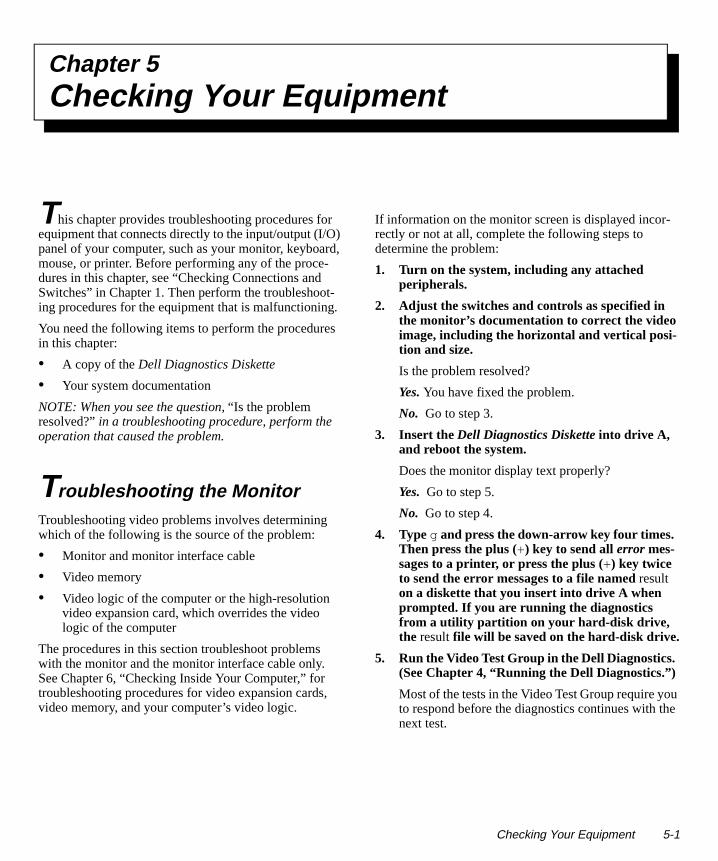
Chapter 5Checkin g Your Equipment
u e
This chapter provides troubleshooting procedures for equipment that connects directly to the input/output (I/O) panel of your computer, such as your monitor, keyboard, mouse, or printer. Before performing any of the proce-dures in this chapter, see “Checking Connections and Switches” in Chapter 1. Then perform the troubleshoot-ing procedures for the equipment that is malfunctioning.
You need the following items to perform the procedures in this chapter:
• A copy of the Dell Diagnostics Diskette
• Your system documentation
NOTE: When you see the question, “Is the problem resolved?” in a troubleshooting procedure, perform the operation that caused the problem.
Troubleshootin g the MonitorTroubleshooting video problems involves determining which of the following is the source of the problem:
• Monitor and monitor interface cable
• Video memory
• Video logic of the computer or the high-resolution video expansion card, which overrides the video logic of the computer
The procedures in this section troubleshoot problems with the monitor and the monitor interface cable only. See Chapter 6, “Checking Inside Your Computer,” for troubleshooting procedures for video expansion cards, video memory, and your computer’s video logic.
If information on the monitor screen is displayed incor-rectly or not at all, complete the following steps to determine the problem:
1. Turn on the system, including any attached peripherals.
2. Adjust the switches and controls as specified in the monitor’s documentation to correct the video image, including the horizontal and vertical posi-tion and size.
Is the problem resolved?
Yes. You have fixed the problem.
No. Go to step 3.
3. Insert the Dell Diagnostics Diskette into drive A, and reboot the system.
Does the monitor display text properly?
Yes. Go to step 5.
No. Go to step 4.
4. Type g and press the down-arrow key four times. Then press the plus (+) key to send all error mes-sages to a printer, or press the plus (+) key twice to send the error messages to a file named result on a diskette that you insert into drive A when prompted. If you are running the diagnostics from a utility partition on your hard-disk drive, the result file will be saved on the hard-disk drive.
5. Run the Video Test Group in the Dell Diagnostics. (See Chapter 4, “Running the Dell Diagnostics.”)
Most of the tests in the Video Test Group require yoto respond before the diagnostics continues with thnext test.
Checking Your Equipment 5-1

he r
he
Do the tests complete successfully?
Yes. You have fixed the problem.
No. Go to step 6.
6. Turn off the system and disconnect it from alter-nating current (AC) power. Swap the monitor with one of the same type that is working, and reconnect the system to AC power.
7. Insert the Dell Diagnostics Diskette into drive A, reboot the system, and run the Video Test Group again.
Do the tests complete successfully?
Yes. You probably need a new monitor. See Chapter 7, “Getting Help,” for instructions on obtaining technical assistance.
No. If you have a video expansion card installed in your computer, see “Troubleshooting Expansion Cards” in Chapter 6.
Troubleshooting the KeyboardThis procedure determines what kind of keyboard prob-lem you have. If a system error message indicates a keyboard problem when you start up the computer sys-tem or during the Dell Diagnostics, complete the following steps:
1. Look at the keyboard and the keyboard cable for any signs of damage. Press and release each key on the keyboard.
Do the keyboard and its cable appear to be free of physical damage, and do the keys work?
Yes. Go to step 3.
No. Go to step 2.
2. Swap the faulty keyboard with a working keyboard.
To swap a faulty keyboard, unplug the keyboard cable from your computer’s back panel and plug in a working keyboard.
Is the problem resolved?
Yes. You probably need a new keyboard. See Chap-ter 7, “Getting Help,” for instructions on obtaining technical assistance.
No. Go to step 3.
3. Insert the Dell Diagnostics Diskette into drive A, reboot the system, and run the Keyboard Test Group in the Dell Diagnostics. (See Chapter 4, “Running the Dell Diagnostics.”)
Can you use the keyboard to select the Keyboard Test Group?
Yes. Go to step 4.
No. Go to step 5.
4. Does the Keyboard Interactive Test complete successfully?
Yes. Go to step 6.
No. Go to step 5.
5. Swap the faulty keyboard with a working keyboard.
6. Does the Keyboard Controller Test complete successfully?
Yes. You need a new keyboard. See Chapter 7, “Get-ting Help,” for instructions on obtaining technical assistance.
No. See Chapter 7, “Getting Help,” for instructionson obtaining technical assistance.
Troubleshooting I/O PortsThis section provides a procedure for troubleshooting tports on your computer’s I/O panel and the equipmentconnected to them, such as a printer, scanner, or otheperipheral device.
You can also use this procedure to test I/O ports on expansion cards. However, you should first complete tprocedures in “Troubleshooting Expansion Cards” in Chapter 6 to verify that the card is configured and installed correctly.
If a system error message indicates a port problem or if equipment connected to a port seems to perform
5-2 Diagnostics and Troubleshooting Guide
lel s- he
incorrectly or not at all, the source of the problem may be any of the following:
• A faulty connection between the I/O port and the peripheral device
• A faulty cable between the I/O port and the periph-eral device
• A faulty peripheral device
• Incorrect settings in the System Setup program
• Incorrect settings in the system’s configuration files
• Faulty I/O port logic on the system board
NOTE: With certain modems installed, the Serial Port Test Group subtests may fail because the modem appears to the diagnostics as a serial port, but it cannot be tested as a serial port. If you have a modem installed and you experience a serial-port test failure, remove the modem and run the diagnostic tests again.
Troubleshooting the Basic I/O FunctionsThis procedure determines whether the computer’s basic I/O functions are operational. If a system error message indicates an I/O port problem or the device connected to the port does not function properly, follow these steps:
1. Enter the System Setup program and check the settings for the Serial Port 1, Serial Port 2, Paral-lel Port, and Mouse categories.
NOTE: Not all systems have a Mouse category in the System Setup program.
Are the communication port categories set to Auto, and is the Mouse category set to On?
Yes. Go to step 3.
No. Go to step 2.
2. Change the setting for the Serial Port 1, Serial Port 2, and Parallel Port categories to Auto, and change the setting for the Mouse category to On; then reboot the system.
Is the problem resolved?
Yes. You have fixed the problem.
No. Go to step 3.
3. Check the contents of your start-up files (such as autoexec.bat and config.sys). (See “Installing and Configuring Software” in Chapter 3.)
Are the port configuration commands correct?
Yes. Go to step 5.
No. Go to step 4.
4. Change the necessary statements in the start-up files.
If the port problem is confined to a particular appli-cation program, see the application program’s documentation for specific port configuration requirements.
Is the problem resolved?
Yes. You have fixed the problem.
No. Go to step 5.
5. Insert the Dell Diagnostics Diskette into drive A, reboot the system, and run the Serial/ Infrared Ports Test Group and/or the Parallel Ports Test Group in the Dell Diagnostics. (See Chapter 4, “Running the Dell Diagnostics.”)
The Serial/Infrared Ports Test Group and the ParalPorts Test Group test the basic functions of the sytem board’s I/O port logic. Also, if a parallel printeris connected to the parallel port, the Parallel PortsTest Group tests the communication link between tsystem board’s I/O port logic and the printer.
Do the tests complete successfully?
Yes. Go to step 6.
No. See Chapter 7, “Getting Help,” for instructionson obtaining technical assistance.
6. If the problem persists, go to “Troubleshooting a Parallel Printer” or “Troubleshooting a Serial I/O Device” found later in this chapter, depending on which device appears to be malfunctioning.
Checking Your Equipment 5-3

7,
Troubleshooting a Parallel PrinterIf the preceding procedure, “Troubleshooting the Basic I/O Functions,” indicates that the problem is with a paral-lel printer, follow these steps:
1. Turn off the parallel printer and computer.
2. Swap the parallel printer interface cable with a known working cable.
3. Turn on the parallel printer and computer.
4. Attempt a print operation on the parallel printer.
Does the print operation complete successfully?
Yes. You probably need a new interface cable. See Chapter 7, “Getting Help,” for instructions on obtaining technical assistance.
No. Go to step 5.
5. Run the parallel printer’s self-test.
Does the self-test complete successfully?
Yes. Go to step 6.
No. The printer is probably defective. If you bought the printer from Dell, see Chapter 7, “Getting Help,” for instructions on obtaining technical assistance. If you bought the printer elsewhere, take it to one of the manufacturer’s authorized service centers for repair.
6. Attempt another print operation on the parallel printer.
Does the print operation complete successfully?
Yes. You have fixed the problem.
No. See Chapter 7, “Getting Help,” for instructions on obtaining technical assistance.
Troubleshooting a Serial I/O DeviceIf the procedure titled “Troubleshooting the Basic I/O Functions” indicates that the problem is with a device connected to one of the serial ports, follow these steps:
1. Turn off the computer and any peripheral devices connected to the serial ports.
Are two serial devices connected to the computer?
Yes. Go to step 2.
No. Go to step 4.
2. Disconnect the devices from serial ports 1 and 2, and connect the malfunctioning serial device to the opposite port.
3. Turn on the computer and the reconnected serial device.
Is the problem resolved?
Yes. The serial port may be defective. See Chapter“Getting Help,” for instructions on obtaining techni-cal assistance.
No. Go to step 4.
4. Turn off the computer and the serial device, and swap the interface cable (that connects the deviceto the serial port) with a known working cable.
5. Turn on the computer and the serial device.
Is the problem resolved?
Yes. You probably need a new interface cable. SeeChapter 7, “Getting Help,” for instructions on obtaining technical assistance.
No. Go to step 6.
6. Turn off the computer and the serial device, and swap the device with a comparable working device.
For example, if your serial mouse has a problem, swap it with a serial mouse you know is working properly.
7. Turn on the computer and the serial device.
Is the problem resolved?
Yes. You probably need a new device. See Chapter 7, “Getting Help,” for instructions on obtaining technical assistance.
No. See Chapter 7, “Getting Help,” for instructionson obtaining technical assistance.
5-4 Diagnostics and Troubleshooting Guide

Chapter 6Checkin g Inside Your Computer
ed g
.
This chapter provides troubleshooting procedures for components inside your computer. Before you start any of the procedures in this chapter, do the following:
• Perform the procedures described in “Checking Con-nections and Switches” and “The System Setup Program” in Chapter 1.
• Read the safety instructions in “Safety First—For You and Your Computer” found next in this chapter.
You need the following items to perform the procedures in this chapter:
• A copy of the Dell Diagnostics Diskette
• Your system documentation
• A small flat-blade screwdriver and a #1 Phillips-head screwdriver (or quarter-inch hex-nut driver)
NOTE: When you see the question, “Is the problem resolved?” in a troubleshooting procedure, perform the operation that caused the problem.
Safety First —For You and Your ComputerThe procedures in this chapter require that you remove the cover and work inside your computer. While working inside your computer, do not attempt to service the com-puter except as explained in this guide and elsewhere in Dell documentation. Always follow the instructions closely.
Working inside your computer is safe—if you observe the following precautions.
In addition, Dell recommends that you periodically review the safety instructions at the front of this guide.
Removin g and Replacin g the Computer CoverTo troubleshoot problems inside your computer, you neto remove the computer cover. Instructions for removinthe computer cover are in your system documentation
WARNING FOR YOUR PERSONAL SAFETYAND PROTECTION OF YOUR EQUIPMENT
Before starting to work on your computer, performthe following steps in the sequence indicated:
1. Turn off your computer and all peripherals.
2. Disconnect your computer and peripherals from their power sources. Doing so reduces the potential for personal injury or shock. Also dis-connect any telephone or telecommunication lines from the computer.
3. Touch an unpainted metal surface on the com-puter chassis, such as the metal around the card-slot openings at the back of your com-puter, before touching anything inside your computer.
While you work, periodically touch an unpainted metal surface on the computer chas-sis to dissipate any static electricity that might harm internal components.
Checking Inside Your Computer 6-1

n or
er:
When you finish your troubleshooting procedure, replace the cover of your computer by following the steps out-lined in your system documentation.
Troubleshooting a Wet ComputerLiquids can damage your computer. While you are not likely to submerge your computer, spills, splashes, and excessive humidity can also cause damage. If an external device (such as a printer or an external drive) gets wet, contact the manufacturer for instructions. If your com-puter gets wet, complete the following steps:
1. Turn off the system, including any attached peripherals, and disconnect all the alternating current (AC) power cables from their power sources. Also, disconnect any telephone or tele-communication lines from the computer.
2. Remove the computer cover.
3. Let the computer dry for at least 24 hours.
Make sure that it is thoroughly dry before proceeding.
4. Remove all expansion cards installed in the com-puter except a drive controller card and video expansion card (if applicable).
See your system documentation for instructions.
5. Replace the computer cover, reconnect the system to AC power, and turn it on.
Does the system have power?
Yes. Go to step 6.
No. See Chapter 7, “Getting Help,” for instructions on obtaining technical assistance.
6. Turn off the system, disconnect it from AC power, remove the computer cover, and reinstall all expansion cards you removed in step 4.
See your system documentation for instructions.
7. Replace the computer cover, and reconnect the system to AC power. Also, reconnect any tele-phone or telecommunication lines to the computer.
8. Insert the Dell Diagnostics Diskette into drive A, reboot the system, and run the System Set Test Group in the Dell Diagnostics. (See Chapter 4, “Running the Dell Diagnostics.”)
Do the tests complete successfully?
Yes. Your system is operating properly.
No. See Chapter 7, “Getting Help,” for instructionson obtaining technical assistance.
Troubleshooting a Damaged ComputerIf your computer was dropped or damaged, you shouldcheck your computer to see if it functions properly. If aexternal device attached to your computer is dropped damaged, contact the manufacturer of the device for instructions or see Chapter 7, “Getting Help,” for infor-mation on obtaining technical assistance from Dell. Follow these steps to troubleshoot a damaged comput
1. Turn off the system, including any attached peripherals, and disconnect all the AC power cables from their power sources. Also, disconnect any telephone or telecommunication lines from the computer.
2. Remove the computer cover.
3. Check all the expansion-card connections in the computer.
See your system documentation for instructions.
4. Verify the diskette/tape drive, hard-disk drive, and all other internal connections (including options such as video-memory upgrade modules, math coprocessors, and microprocessor upgrades).
CAUTION: See “Protecting Against Electro-static Discharge” in the safety instructions atthe front of this guide.
CAUTION: See “Protecting Against Electro-static Discharge” in the safety instructions atthe front of this guide.
6-2 Diagnostics and Troubleshooting Guide

nto a ec-
or
Make sure that all cables are properly connected and that all components are properly seated in their con-nectors and sockets.
See your system documentation for instructions.
5. Replace the computer cover, reconnect the system to AC power, and reconnect any telephone or tele-communication lines.
6. Insert the Dell Diagnostics Diskette into drive A, and reboot the system.
7. Run the System Set Test Group in the Dell Diag-nostics. (See Chapter 4, “Running the Dell Diagnostics.”)
Do the tests complete successfully?
Yes. Your system is operating properly.
No. See Chapter 7, “Getting Help,” for instructions on obtaining technical assistance.
Troubleshooting the Battery
If an error message indicates a problem with the battery or if the System Setup program loses the system configu-ration information when the computer is turned off, the battery may be defective.
Follow these steps to troubleshoot the battery:
1. Turn off the system, including any attached peripherals, and disconnect all the AC power cables from their power sources. Also, disconnect any telephone or telecommunication lines from the computer.
2. Remove the computer cover.
3. Check the connection of the battery to the system board.
Some systems have a coin cell battery that snaps ia socket on the system board. Other systems havebattery with a cable that attaches to a header conntor on the system board.
Is the battery firmly attached to the battery socket connector on the system board?
Yes. Go to step 5.
No. Go to step 4.
4. Reseat the battery in its socket, or reconnect the battery cable to the system board.
Is the problem resolved?
Yes. The connection was loose. You have fixed theproblem.
No. Go to step 5.
5. Replace the battery.
See your system documentation for instructions.
Is the problem resolved?
Yes. The battery’s charge was low. You have fixed the problem.
No. See Chapter 7, “Getting Help,” for instructionson obtaining technical assistance.
WARNING
There is a danger of a new battery exploding if it isincorrectly installed. Replace the battery only withthe same or equivalent type recommended by themanufacturer. Discard used batteries according tothe manufacturer’s instructions.
CAUTION: See “Protecting Against Electro-static Discharge” in the safety instructions atthe front of this guide.
Checking Inside Your Computer 6-3

s
t/
Troubleshooting Expansion CardsIf an error message indicates an expansion-card problem or if an expansion card seems to perform incorrectly or not at all, the problem could be a faulty connection, a conflict with software or other hardware, or a faulty expansion card. Follow these steps to troubleshoot expansion cards:
1. Turn off the system, including any attached peripherals, and disconnect all the AC power cables from their power sources. Also, disconnect any telephone or telecommunication lines from the computer.
2. Remove the computer cover.
3. Verify that each expansion card is firmly seated in its connector.
Are the expansion cards properly seated in their connectors?
Yes. Go to step 5.
No. Go to step 4.
4. Reseat the expansion cards in their connectors.
See your system documentation for instructions.
Is the problem resolved?
Yes. The connection was loose. You have fixed the problem.
No. Go to step 5.
5. Verify that the appropriate cables are firmly con-nected to their corresponding connectors on the expansion cards.
For instructions on which cables should be attached to specific connectors on an expansion card, see the expansion card’s documentation.
Are the appropriate cables firmly attached to their connectors?
Yes. Go to step 7.
No. Go to step 6.
6. Reconnect the cable connectors to the appropri-ate connectors on the expansion cards.
Is the problem resolved?
Yes. The cable connections were loose. You have fixed the problem.
No. Go to step 7.
7. Inspect all jumpers and configuration switches on each expansion card.
Most Industry-Standard Architecture (ISA) expansion cards have configuration settings for aninterrupt request (IRQ) line, a direct memory acces(DMA) channel, and a base-memory or basic inpuoutput system (BIOS) address. To keep expansioncards from conflicting with each other, you need toknow both the starting memory address and the amount of memory required by each card. For instructions on jumpers and configuration settings,see the expansion card’s documentation.
Is each expansion card configured correctly?
Yes. Go to step 9.
No. Go to step 8.
8. Reconfigure the card according to the instruc-tions in the card’s documentation.
Is the problem resolved?
Yes. The memory configuration of the card was incorrect. You have fixed the problem.
No. Go to step 9.
9. Inspect all configuration jumpers on the system board to ensure that they are configured correctly for any installed expansion cards.
For information on the configuration jumpers and their settings, see your system documentation.
Are the system board’s configuration jumpers set correctly?
Yes. Go to step 11.
No. Go to step 10.
CAUTION: See “Protecting Against Electro-static Discharge” in the safety instructions atthe front of this guide.
6-4 Diagnostics and Troubleshooting Guide

h-
a )
h y ck ; e .
ys-
10. Correct the system board’s configuration jumper settings.
Is the problem resolved?
Yes. You have fixed the problem.
No. Go to step 11.
11. Remove all expansion cards except the hard-disk drive controller card (if one is installed).
See your system documentation for instructions.
12. Replace the computer cover, reconnect the system to AC power, and turn it on.
13. Enter the System Setup program, and update the system configuration information.
14. Insert the Dell Diagnostics Diskette into drive A, reboot the system, and run the RAM Test Group in the Dell Diagnostics. (See Chapter 4, “Running the Dell Diagnostics.”)
Do the tests complete successfully?
Yes. Go to step 15.
No. See Chapter 7, “Getting Help,” for information on obtaining technical assistance.
15. Turn off the system, disconnect it from AC power, and remove the computer cover.
16. Reinstall one of the expansion cards you removed in step 11, and repeat steps 12 and 13.
17. Insert the Dell Diagnostics Diskette into drive A, and reboot the system. Run the RAM Test Group in the Dell Diagnostics.
Do the tests complete successfully?
Yes. Go to step 18.
No. See Chapter 7, “Getting Help,” for information on obtaining technical assistance.
18. Remove the Dell Diagnostics Diskette from drive A. Repeat steps 15, 16, and 17 for each of the remaining expansion cards that you removed in step 11.
Have you reinstalled all of the expansion cards witout encountering a test failure?
Yes. You have fixed the problem.
No. See Chapter 7, “Getting Help,” for informationon obtaining technical assistance.
Troubleshooting System MemoryA computer memory problem can be a faulty single in-line memory module (SIMM), an improperly configuredor faulty memory expansion card (if one is installed), orfaulty system board. If a random-access memory (RAMerror message appears, the computer probably has a memory problem.
When you turn on or reboot the system, the Caps Lockand Scroll Lock indicators on the keyboard should flasmomentarily and then turn off. If the Num Lock categorin the System Setup program is set to On, the Num Loindicator should flash momentarily and then remain onotherwise, it should turn off. Abnormal operation of thesindicators can result from a defective SIMM in socket AFollow these steps to troubleshoot system memory:
1. Turn on the system, including any attached peripherals.
Does an error message appear indicating invalid stem configuration information after the memory count completes?
Yes. Go to step 2.
No. Go to step 8.
2. Enter the System Setup program to check the Total Memory or System Memory category.
Does the amount of memory installed match the Total Memory or System Memory setting?
Yes. Go to step 8.
No. Go to step 3.
Checking Inside Your Computer 6-5

?
,
e
3. Turn off the system, including any attached peripherals, and disconnect all the AC power cables from their power sources. Also, disconnect any telephone or telecommunication lines from the computer.
4. Remove the computer cover.
5. Reseat the SIMMs in their sockets.
See your system documentation for instructions.
6. Replace the computer cover, reconnect the system to AC power, and turn it on.
7. Enter the System Setup program to check the Total Memory or System Memory category again.
Does the amount of memory installed match the Total Memory or System Memory setting?
Yes. Go to step 8.
No. Go to step 9.
8. Reboot the system, and observe the monitor screen and the Num Lock, Caps Lock, and Scroll Lock indicators on the keyboard.
Does the monitor screen remain blank, and do the Num Lock, Caps Lock, and Scroll Lock indicators on the keyboard remain on?
Yes. Go to step 9.
No. Go to step 11.
9. Turn off the system, disconnect it from AC power, and remove the computer cover.
10. If possible, swap the SIMM in socket A with one of the same capacity, reboot the system, and observe the monitor screen and the indicators on the keyboard.
Is the problem resolved?
Yes. You have fixed the problem.
No. Go to step 11.
11. Determine whether there is a memory expansion card installed in an expansion slot.
Is a memory expansion card installed?
Yes. Go to step 12.
No. Go to step 14.
12. Check the memory expansion card’s documenta-tion to determine whether the card is configured correctly.
Is the memory expansion card configured correctly
Yes. Go to step 13.
No. Go to step 14.
13. Reconfigure the memory expansion card.
14. Replace the computer cover, reconnect the systemto AC power, reconnect any telephone or telecom-munication lines and turn it on.
15. Insert the Dell Diagnostics Diskette into drive A, reboot the system, and run the RAM Test Group in the Dell Diagnostics. (See Chapter 4, “Running the Dell Diagnostics.”)
Do the tests complete successfully?
Yes. You have fixed the problem.
No. See Chapter 7, “Getting Help,” for instructionson obtaining technical assistance.
Troubleshooting the Video Subsystem Troubleshooting video problems involves determining which of the following is the source of the problem: themonitor, the monitor interface cable, the video memoryor the video logic of the computer. You can also have ahigh-resolution video expansion card installed, which overrides the video logic of the computer.
The following procedure troubleshoots problems with thvideo memory and video logic only. Before you begin, perform the procedure found in “Troubleshooting the Monitor” in Chapter 5 to determine whether or not the monitor is the source of the problem.
CAUTION: See “Protecting Against Electro-static Discharge” in the safety instructions atthe front of this guide.
6-6 Diagnostics and Troubleshooting Guide

.
If you have a high-resolution video expansion card, first complete the steps in “Troubleshooting Expansion Cards” found earlier in this chapter to verify that the card is configured and installed correctly.
Follow these steps to troubleshoot the video subsystem:
1. Insert the Dell Diagnostics Diskette into drive A, reboot the system, and run the Video Test Group in the Dell Diagnostics. (See Chapter 4, “Running the Dell Diagnostics.”)
Most of the tests in the Video Test Group are interac-tive; that is, you must respond before the diagnostics continues with the next test.
Do the tests complete successfully?
Yes. It is not a video hardware problem. Go to Chap-ter 3, “Finding Software Solutions.”
No. Go to step 2.
2. Turn off the system, including any attached peripherals, and disconnect all the AC power cables from their power sources. Also, disconnect any telephone or telecommunication lines from the computer.
3. Remove the computer cover.
4. Check the system-board configuration jumpers.
See your system documentation for a list of the sys-tem board jumpers and their settings.
Are the jumpers set correctly?
Yes. Go to step 9.
No. Go to step 5.
5. Correct the configuration jumper settings on the system board.
6. Replace the computer cover, reconnect the system to AC power, reconnect any telephone or telecom-munication lines and turn it on.
7. Insert the Dell Diagnostics Diskette into drive A, and reboot the system. Run the Video Test Group again.
Is the problem resolved?
Yes. The configuration jumpers were set incorrectlyYou have fixed the problem.
No. Go to step 8.
8. Turn off the system, disconnect it from AC power, and remove the computer cover. Also, disconnect any telephone or telecommunication lines from the computer.
9. Determine whether a video-memory upgrade module is installed.
See your system documentation for the location ofthe video-memory upgrade module.
Is a video-memory upgrade module installed?
Yes. Go to step 10.
No. Go to step 11.
10. Reseat the video-memory upgrade module.
See your system documentation for instructions.
11. Replace the computer cover, reconnect the systemto AC power, reconnect any telephone or telecom-munication lines and turn it on.
12. Insert the Dell Diagnostics Diskette into drive A, and reboot the system. Run the Video Test Group again.
Do the tests complete successfully?
Yes. The video-memory upgrade module was not connected properly. You have fixed the problem.
No. Go to step 13.
13. Turn off the system, disconnect it from AC power, and remove the computer cover. Also, disconnect any telephone or telecommunication lines from the computer.
14. Determine whether a video expansion card is installed.
Is a video expansion card installed?
Yes. Go to step 15.
CAUTION: See “Protecting Against Electro-static Discharge” in the safety instructions atthe front of this guide.
Checking Inside Your Computer 6-7

h-
No. See Chapter 7, “Getting Help,” for instructions on obtaining technical assistance.
15. Remove the video expansion card, and repeat steps 11 and 12.
Do the tests complete successfully?
Yes. The video expansion card is faulty. See Chapter 7, “Getting Help,” for instructions on obtaining tech-nical assistance.
No. See Chapter 7, “Getting Help,” for instructions on obtaining technical assistance.
Troubleshooting the System BoardA system board problem can result from a defective system board component, a faulty power supply, or a defective component connected to the system board. If an error message indicates a system board problem, follow these steps to find the problem:
1. Turn off the system, including any attached peripherals, and disconnect all the AC power cables from their power sources. Also, disconnect any telephone or telecommunication lines from the computer.
2. Remove the computer cover.
3. Remove all expansion cards except the hard-disk drive controller card and the video expansion card (if they are installed).
4. Replace the computer cover, reconnect the system to AC power, and turn it on.
5. Enter the System Setup program, and update the system configuration information.
6. Insert the Dell Diagnostics Diskette into drive A, and reboot the system. Run the System Set Test Group in the Dell Diagnostics. (See Chapter 4, “Running the Dell Diagnostics.”)
Do the tests complete successfully?
Yes. Go to step 7.
No. Go to step 12.
7. Remove the Dell Diagnostics Diskette from drive A , turn off the system, disconnect it from AC power, and remove the computer cover.
8. Reinstall one of the expansion cards you removedin step 3, and repeat steps 4 and 5.
See your system documentation for instructions.
9. Insert the Dell Diagnostics Diskette into drive A, and reboot the system. Run the System Set Test Group again.
Do the tests complete successfully?
Yes. Go to step 10.
No. Go to step 12.
10. Turn off the system, disconnect it from AC power, and remove the computer cover.
11. Repeat steps 7, 8, and 9 for each of the remainingexpansion cards you removed in step 3.
Have you reinstalled all of the expansion cards witout encountering a test failure?
Yes. Go to step 12.
No. Your expansion card is faulty. See Chapter 7, “Getting Help,” for instructions on obtaining techni-cal assistance.
12. Disconnect the keyboard and reboot the system.
Does the system boot successfully?
Yes. Go to step 13.
No. Go to step 14.
CAUTION: See “Protecting Against Electro-static Discharge” in the safety instructions atthe front of this guide.
6-8 Diagnostics and Troubleshooting Guide
r
re.
at-
-
-
s
13. Swap the keyboard with a comparable working keyboard, and run the System Set Test Group again.
Do the tests complete successfully?
Yes. You have fixed the problem.
No. Go to step 14.
14. See Chapter 7, “Getting Help,” for instructions on obtaining technical assistance.
Troubleshooting the Diskette/Tape Drive SubsystemIf the monitor displays a system error message indicating a diskette drive problem during execution of either the boot routine or the Dell Diagnostics, the problem may be caused by any of the following conditions:
• The system configuration settings do not match the physical diskette/tape drive subsystem configuration.
• The diskette/tape drive cables are not properly con-nected or are faulty.
• An expansion card is interfering with proper drive operations.
• A diskette drive may be improperly configured.
• The diskette drive or tape drive is faulty.
• The computer’s power supply is not providing suffi-cient power for the drives.
• The computer’s diskette/tape drive logic is faulty.
In any computer that has multiple drives, a problem with one drive can affect the entire subsystem. Therefore, the troubleshooting procedures for the diskette/tape drive subsystem are divided into the following subsections:
• “Checking the Diskette/Tape Drive Subsystem”
• “Troubleshooting a Diskette-Drive Subsystem”
• “Troubleshooting a Non-SCSI Internal Tape Drive”
• “Troubleshooting a SCSI Tape Drive”
Before you begin the troubleshooting procedures, com-plete steps 1 and 2 in the next subsection, “Checking the Diskette/Tape Drive Subsystem,” to verify that the sys-
tem configuration information is correct for the installeddiskette drive(s).
If, after completing these steps, the system boots cor-rectly and the monitor no longer displays a system erromessage, the problem is resolved. If you continue to have problems, however, proceed with the appropriatediskette/tape drive subsystem troubleshooting procedu
Checking the Diskette/Tape Drive SubsystemTo verify that the diskette/tape drive subsystem is opering properly, follow these steps:
1. Enter the System Setup program, and verify that the system is configured correctly for the Diskette Drive A and Diskette Drive B categories.
See your system documentation for instructions.
2. If the system configuration settings are incorrect, make the necessary corrections in the System Setup program, and then reboot the system.
3. Insert the Dell Diagnostics Diskette into drive A, reboot the system, and run the Diskette Drives Test Group in the Dell Diagnostics to see whether the diskette/tape drive subsystem now works correctly.
See Chapter 4, “Running the Dell Diagnostics,” formore information.
Do the tests complete successfully?
Yes. Continue with the next step in the procedure you were performing.
No. See Chapter 7, “Getting Help,” for instructionson obtaining technical assistance.
Troubleshooting a Diskette-Drive SubsystemIf you receive a system error message indicating a diskette drive problem, insert the Dell Diagnostics Diskette into drive A, and reboot the system by turning the computer off, allowing the hard-disk drive(s) to spin down, and turning the computer on again.
NOTE: You must leave the Dell Diagnostics Diskette in drive A throughout this entire procedure except for stepthat specifically require you to remove it.
Checking Inside Your Computer 6-9
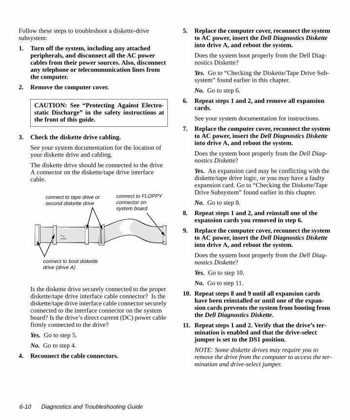
-
e
ter-
Follow these steps to troubleshoot a diskette-drive subsystem:
1. Turn off the system, including any attached peripherals, and disconnect all the AC power cables from their power sources. Also, disconnect any telephone or telecommunication lines from the computer.
2. Remove the computer cover.
3. Check the diskette drive cabling.
See your system documentation for the location of your diskette drive and cabling.
The diskette drive should be connected to the drive A connector on the diskette/tape drive interface cable.
Is the diskette drive securely connected to the proper diskette/tape drive interface cable connector? Is the diskette/tape drive interface cable connector securely connected to the interface connector on the system board? Is the drive’s direct current (DC) power cable firmly connected to the drive?
Yes. Go to step 5.
No. Go to step 4.
4. Reconnect the cable connectors.
5. Replace the computer cover, reconnect the systemto AC power, insert the Dell Diagnostics Diskette into drive A, and reboot the system.
Does the system boot properly from the Dell Diag-nostics Diskette?
Yes. Go to “Checking the Diskette/Tape Drive Subsystem” found earlier in this chapter.
No. Go to step 6.
6. Repeat steps 1 and 2, and remove all expansion cards.
See your system documentation for instructions.
7. Replace the computer cover, reconnect the systemto AC power, insert the Dell Diagnostics Diskette into drive A, and reboot the system.
Does the system boot properly from the Dell Diag-nostics Diskette?
Yes. An expansion card may be conflicting with thediskette/tape drive logic, or you may have a faulty expansion card. Go to “Checking the Diskette/TapDrive Subsystem” found earlier in this chapter.
No. Go to step 8.
8. Repeat steps 1 and 2, and reinstall one of the expansion cards you removed in step 6.
9. Replace the computer cover, reconnect the systemto AC power, insert the Dell Diagnostics Diskette into drive A, and reboot the system.
Does the system boot properly from the Dell Diag-nostics Diskette?
Yes. Go to step 10.
No. Go to step 11.
10. Repeat steps 8 and 9 until all expansion cards have been reinstalled or until one of the expan-sion cards prevents the system from booting from the Dell Diagnostics Diskette.
11. Repeat steps 1 and 2. Verify that the drive’s ter-mination is enabled and that the drive-select jumper is set to the DS1 position.
NOTE: Some diskette drives may require you to remove the drive from the computer to access the mination and drive-select jumper.
CAUTION: See “Protecting Against Electro-static Discharge” in the safety instructions atthe front of this guide.
connect to boot diskette drive (drive A)
connect to tape drive or second diskette drive
connect to FLOPPY connector on system board
6-10 Diagnostics and Troubleshooting Guide

h
r
u
?
For information about the drive’s termination and drive-select jumper settings, refer to the documenta-tion for the drive.
Is the drive configured correctly?
Yes. Go to step 14.
No. Go to step 12.
12. Correct the drive-select jumper setting and ter-minator installation.
13. Replace the computer cover, reconnect the system to AC power, insert the Dell Diagnostics Diskette into drive A, and reboot the system.
Does the system boot properly from the Dell Diag-nostics Diskette?
Yes. Go to “Checking the Diskette/Tape Drive Sub-system” found earlier in this chapter.
No. Go to step 14.
14. See Chapter 7, “Getting Help,” for instructions on obtaining technical assistance.
Troubleshooting a Non-SCSI Internal Tape DriveIn a drive configuration containing both a single diskette drive and an internal tape drive that is not a small com-puter system interface (SCSI) drive, the diskette drive and the tape drive are connected, respectively, to the drive A and drive B connectors on the diskette/tape drive interface cable. When the internal diskette/tape drive sub-system is configured in this manner, the Drive B category on the System Board Options screen in the EISA Config-uration Utility and the Diskette Drive B category in the System Setup program must be set to Not Installed to prevent interference with tape drive operation.
NOTE: Some systems may have an external tape drive, in which case a special tape-drive controller card must be installed in one of the expansion slots. The troubleshoot-ing procedure in this subsection applies specifically to internal tape drives.
Tape drive problems usually result from a defective tape drive, a defective tape cartridge, or software. Follow
these steps to troubleshoot a non-SCSI internal tape drive:
1. Remove the tape that was in use when the prob-lem occurred, and replace it with a tape that you know is not defective.
Is the problem resolved?
Yes. The original tape was defective. Replace it wita new tape. You have fixed the problem.
No. Go to step 2.
2. Remove any installed terminate-and-stay-resident (TSR) programs.
See “Memory-Resident Programs” in Chapter 3 foinformation about unloading TSR programs.
Is the problem resolved?
Yes. The TSR program was conflicting with the tapebackup software. You have fixed the problem.
No. Go to step 3.
3. Reinstall the tape backup software as instructed in the tape-backup software documentation.
Is the problem resolved?
Yes. The tape backup software was corrupted. Yohave fixed the problem.
No. Go to step 4.
4. If the system contains a single diskette drive, enter the System Setup program, and verify that the Diskette Drive B category is set to Not Installed.
See your system documentation for instructions.
Is the Diskette Drive B category set to Not Installed
Yes. Go to step 6.
No. Go to step 5.
5. Correct the Diskette Drive B category setting.
Is the problem resolved?
Yes. The system configuration information was incorrect. You have fixed the problem.
No. Go to step 6.
Checking Inside Your Computer 6-11
or r
rol
s
h
r
6. Turn off the system, including any attached peripherals, and disconnect all the AC power cables from their power sources. Also, disconnect any telephone or telecommunication lines from the computer.
7. Remove the computer cover.
8. Check the interface cable connections to the tape drive and to the interface connector on the system board or the controller card (if one is installed). Check the DC power cable connection to the tape drive.
Are the cables firmly connected?
Yes. Go to step 10.
No. Go to step 9.
9. Reseat the cable connectors, replace the computer cover, reconnect the system to AC power, and turn it on.
Is the problem resolved?
Yes. The connections were loose. You have fixed the problem.
No. Go to step 10.
10. Turn off the system, disconnect it from AC power, and remove the computer cover.
11. Remove the tape drive, and ensure that the input/output (I/O) address and IRQ jumper settings do not conflict with any other device’s settings.
See “Avoiding Interrupt Assignment Conflicts” in Chapter 3. For information on setting the jumpers, see the documentation for the tape drive.
Are the drive’s jumpers positioned correctly?
Yes. Go to step 13.
No. Go to step 12.
12. Correct the drive’s jumper settings according to the documentation for the tape drive, and rein-stall the tape drive.
13. Replace the computer cover, reconnect the systemto AC power, reconnect any telephone or telecom-munication lines, and turn on the computer.
Is the problem resolved?
Yes. The IRQ jumper settings were incorrect. You have fixed the problem.
No. See Chapter 7, “Getting Help” for instructions on obtaining technical assistance.
Troubleshooting a SCSI Tape DriveA SCSI tape drive can be either an internal device installed in one of the externally accessible drive bays an external device that attaches to a SCSI host adapteconnector on the back panel of the computer. In eithercase, the SCSI tape drive is controlled by a SCSI hostadapter installed in the computer, which may also contother SCSI devices connected to one or more SCSI cables. SCSI devices sometimes require device driverfor the particular operating system being used by the computer system.
Tape drive problems often result from a defective tapedrive, a defective tape cartridge, or software. Follow these steps to troubleshoot a SCSI tape drive:
1. Remove the tape that was in use when the prob-lem occurred, and replace it with a tape that you know is not defective.
Is the problem resolved?
Yes. The original tape was defective. Replace it wita new tape. You have fixed the problem.
No. Go to step 2.
2. Remove any installed TSR programs.
See “Memory-Resident Programs” in Chapter 3 foinformation about unloading TSR programs.
Is the problem resolved?
Yes. The TSR program was conflicting with the tapebackup software. You have fixed the problem.
No. Go to step 3.
CAUTION: See “Protecting Against Electro-static Discharge” in the safety instructions atthe front of this guide.
6-12 Diagnostics and Troubleshooting Guide

r
c-
3. Verify that any required SCSI device drivers are installed on the hard-disk drive and are config-ured correctly.
If the computer system is using a built-in SCSI host adapter or a Dell Advanced SCSI Host (DASH) Bus Adapter card, see the SCSI Device Driver Installa-tion and Configuration Guide for instructions on installing and configuring the SCSI device drivers. For any other type of SCSI host adapter card, see the documentation that accompanied the host adapter card.
Are the drivers installed and configured correctly?
Yes. The SCSI device drivers were installed or con-figured incorrectly or were corrupted. You have fixed the problem.
No. Go to step 4.
4. Reinstall the tape backup software as instructed in the tape-backup software documentation.
Is the problem resolved?
Yes. The tape backup software was corrupted. You have fixed the problem.
No. Go to step 5.
5. Turn off the system, including any attached peripherals, and disconnect all the AC power cables from their power sources. Also, disconnect any telephone or telecommunication lines from the computer.
6. Remove the computer cover.
7. Check the SCSI cable connections to the tape drive and to the SCSI host adapter connector. If the tape drive is an internal device, check the DC power cable connection to the tape drive.
Are the cables firmly connected?
Yes. Go to step 9.
No. Go to step 8.
8. Reseat the cable connectors, replace the computecover, reconnect the system to AC power, and turn it on.
Is the problem resolved?
Yes. You have fixed the problem.
No. Go to step 9.
9. Turn off the system, including any attached peripherals, and disconnect all the AC power cables from their power sources. Then remove the computer cover.
10. Remove the tape drive. Then verify that the tape drive is configured for a unique SCSI identifica-tion (ID) number and that the tape drive’s termination is enabled or disabled as appropriate.
See the documentation for the tape drive for instrutions on selecting the SCSI ID and enabling or disabling termination.
Is the tape drive configured correctly?
Yes. Go to step 13.
No. Go to step 11.
11. Reconfigure the tape drive’s SCSI ID and termi-nation settings as appropriate. Reinstall the tape drive, replace the computer cover, reconnect the system to AC power, and turn it on.
Is the problem resolved?
Yes. The tape drive was configured incorrectly. Youhave fixed the problem.
No. Go to step 12.
12. Turn off the system, including any attached peripherals, and disconnect all the AC power cables from their power sources. Then remove the computer cover.
13. Replace the SCSI cable that connects the tape drive to the SCSI host adapter connector.
CAUTION: See “Protecting Against Electro-static Discharge” in the safety instructions atthe front of this guide.
Checking Inside Your Computer 6-13
e
r
14. Replace the computer cover, reconnect the system to AC power, reconnect any telephone or telecom-munication lines, and turn on the computer.
Is the problem resolved?
Yes. You have fixed the problem.
No. See Chapter 7, “Getting Help,” for instructions on obtaining technical assistance.
Troubleshooting Hard-Disk DrivesHard-disk drive problems can be caused by a number of conditions, including problems with the drive itself, a hard-disk drive controller card, the optional SCSI back-plane board, the SCSI host adapter, or an interface cable. This section is further subdivided into three procedures for troubleshooting hard-disk drives:
• “Troubleshooting IDE Hard-Disk Drives”
• “Troubleshooting SCSI Hard-Disk Drives in a Sys-tem Without a SCSI Backplane Board”
• “Troubleshooting SCSI Hard-Disk Drives in a Sys-tem With a SCSI Backplane Board”
Troubleshooting IDE Hard-Disk DrivesUse the following procedure to troubleshoot a hard-disk drive problem if your system includes one or more inte-grated drive electronics (IDE) hard-disk drives.
1. Boot the system from a diskette, enter the System Setup program, and verify that the hard-disk drive categories are set correctly for the installed hard-disk drives.
Refer to your system documentation for the correct settings of these categories. You can also use the automatic drive-type detect feature to correctly set the drive-type number and the drive parameters for each drive.
Are the system configuration settings correct for thinstalled hard-disk drive?
Yes. Go to step 3.
No. Go to step 2.
2. Correct the system configuration settings, and reboot the system.
Is the problem resolved?
Yes. The system configuration settings were set incorrectly. You have fixed the problem.
No. Go to step 3.
3. Turn off the system, including any attached peripherals, and disconnect all the AC power cables from their power sources. Also, disconnect any telephone or telecommunication lines from the computer.
4. Remove the computer cover.
5. Check the hard-disk drive interface cable connec-tions to the drive and to the IDE connector on the system board or the controller card (if one is installed). Check the DC power cable connection to the drive.
Are the cables firmly connected?
Yes. Go to step 7.
No. Go to step 6.
6. Reseat the cable connectors, replace the computecover, reconnect the system to AC power, and turn it on.
Is the problem resolved?
Yes. The cables were loose. You have fixed the problem.
No. Go to step 7.
7. Turn off the system, disconnect it from AC power, and remove the computer cover.
8. Remove the hard-disk drive.
CAUTION: This troubleshooting procedure candestroy data stored on the hard-disk drive. Beforeyou proceed, make sure you have backed up all thefiles on your hard-disk drive.
CAUTION: See “Protecting Against Electro-static Discharge” in the safety instructions atthe front of this guide.
6-14 Diagnostics and Troubleshooting Guide
k I
-
r
9. Check the hard-disk drive’s jumpers and the con-troller card’s jumpers (if a controller card is installed). (For an Industry-Standard Architec-ture [ISA] card, check the settings on the card itself; for an Extended Industry-Standard Archi-tecture [EISA] card, check the settings through the EISA Configuration Utility.)
For a description of the jumper settings for the drive or controller card, see the documentation for the drive or controller card.
Are the jumpers positioned correctly?
Yes. Go to step 11.
No. Go to step 10.
10. Correct the jumper settings for the drive and/or controller card as instructed by the documenta-tion for the drive and reinstall the hard-disk drive.
11. Replace the computer cover, reconnect the system to AC power, reconnect any telephone or telecom-munication lines to the computer, and turn on the computer.
12. Listen for the drive spinning up after the power supply turns on.
Can you hear the drive spinning up?
Yes. Go to step 13.
No. Go to step 14.
13. Partition and logically format the hard-disk drive. If possible, restore the files to the drive.
To partition and logically format the drive, see the documentation for the computer’s operating system.
Is the problem resolved?
Yes. The hard-disk drive’s file structure was proba-bly corrupt. You have fixed the problem.
No. Go to step 14.
14. See Chapter 7, “Getting Help,” for instructions on obtaining technical assistance.
Troubleshooting SCSI Hard-Disk Drives in a System Without a SCSI Backplane BoardUse the following procedure to troubleshoot a hard-disdrive problem if your system includes one or more SCShard-disk drives and does not contain a SCSI backplane board.
1. Boot the system from a diskette, and enter the System Setup program.
Are both of the hard-disk drive categories set to None?
Refer to your system documentation for more information about the hard-disk drive categories.
Yes. Go to step 3.
No. Go to step 2.
2. Change both categories to None, and reboot the system.
Is the problem resolved?
Yes. The system configuration settings were set incorrectly. You have fixed the problem.
No. Go to step 3.
3. Verify that any required SCSI device drivers are installed and configured correctly.
If the system is using the built-in SCSI host adapteor the DASH Bus Adapter card, see the SCSI Device Driver Installation and Configuration Guide to determine which drivers are required and how theyshould be installed and configured.
Are the required SCSI device drivers installed andconfigured correctly?
Yes. Go to step 5.
No. Go to step 4.
CAUTION: This troubleshooting procedure candestroy data stored on the hard-disk drive. Beforeyou proceed, make sure you have backed up all thefiles on your hard-disk drive.
Checking Inside Your Computer 6-15

or
.
.
4. Reinstall and/or reconfigure the required SCSI device drivers. Then reboot the system.
Is the problem resolved?
Yes. You have fixed the problem.
No. Go to step 5.
5. Turn off the system, including any attached peripherals, and disconnect all the AC power cables from their power sources. Also, disconnect any telephone or telecommunication lines from the computer.
6. Remove the computer cover.
7. Check the SCSI cable connection to the drive and to the SCSI host adapter. Check the DC power cable connection to the drive.
Are the cables firmly connected?
Yes. Go to step 9.
No. Go to step 8.
8. Reseat the cable connectors, replace the computer cover, reconnect the system to AC power, recon-nect any telephone or telecommunication lines to the computer, and turn it on.
Is the problem resolved?
Yes. The cables were loose. You have fixed the problem.
No. Go to step 9.
9. Turn off the system, disconnect it from AC power, disconnect any telephone or telecommunication lines from the computer, and remove the com-puter cover.
10. Remove the hard-disk drive.
11. Verify that the hard-disk drive is configured for a unique SCSI ID and that termination is enabled or disabled as appropriate.
See the documentation for the hard-disk drive for instructions on selecting the SCSI ID and enabling disabling termination.
Is the hard-disk drive configured correctly?
Yes. Go to step 13.
No. Go to step 12.
12. Reconfigure the hard-disk drive’s SCSI ID and termination settings as appropriate. Reinstall the hard-disk drive. Replace the computer cover, reconnect the system to AC power, and turn it on.
Is the problem resolved?
Yes. The hard-disk drive was configured incorrectlyYou have fixed the problem.
No. Go to step 13.
13. Replace the SCSI cable connecting the drive to the SCSI host adapter. Replace the computer cover, reconnect the system to AC power, recon-nect any telephone or telecommunication lines to the computer.and turn it on.
Is the problem resolved?
Yes. The SCSI cable was faulty. You have fixed theproblem.
No. Go to step 14.
14. Partition and logically format the hard-disk drive. If possible, restore the files to the drive.
To partition and logically format the drive, see the documentation for the computer’s operating system
Is the problem resolved?
Yes. The hard-disk drive’s file structure was proba-bly corrupt. You have fixed the problem.
No. Go to step 15.
15. See Chapter 7, “Getting Help,” for instructions on obtaining technical assistance.
CAUTION: See “Protecting Against Electro-static Discharge” in the safety instructions atthe front of this guide.
6-16 Diagnostics and Troubleshooting Guide

Troubleshooting SCSI Hard-Disk Drives in a System With a SCSI Backplane BoardUse the following procedure to troubleshoot a hard-disk drive problem if your system contains an optional SCSI backplane board.
1. Boot the system from a diskette, and enter the System Setup program.
Are both of the hard-disk drive categories set to None?
Yes. Go to step 3.
No. Go to step 2.
2. Change both categories to None, and reboot the system.
Is the problem resolved?
Yes. You have fixed the problem.
No. Go to step 3.
3. Verify that any required SCSI device drivers are installed and configured correctly.
If the system is using the built-in SCSI host adapter or the DASH Bus Adapter card, see the SCSI Device Driver Installation and Configuration Guide to determine which drivers are required and how they should be installed and configured.
Are the required SCSI device drivers installed and configured correctly?
Yes. Go to step 5.
No. Go to step 4.
4. Reinstall and/or reconfigure the required SCSI device drivers. Then reboot the system.
Is the problem resolved?
Yes. You have fixed the problem.
No. Go to step 5.
5. Determine whether the system has a Dell SCSI Array (DSA) controller card.
Does the system have a DSA controller card?
Yes. Go to step 6.
No. Go to step 15.
6. Run the DSA Manager program to see if it can determine which hard-disk drive is faulty.
See the Dell SCSI Array User’s Guide for instruc-tions on running the DSA Manager.
Can the DSA Manager identify the faulty drive?
Yes. Go to step 26.
No. Go to step 7.
7. Remove the computer cover.
8. Check the hard-disk drive failure indicator on the front of each hard-disk drive carrier.
Is the hard-disk drive failure indicator on or blinkingfor any of the drive carriers?
Yes. Go to step 26.
No. Go to step 9.
9. Check the online indicator on the front of each hard-disk drive carrier.
Is the online indicator on for each drive carrier?
Yes. Go to step 13.
No. Go to step 10.
10. Press the release button on the front of the drive carrier.
Does the online indicator blink and then turn on?
Yes. The drive carrier was not installed into the array. You have fixed the problem.
No. Go to step 11.
CAUTION: This troubleshooting procedure candestroy data stored on the hard-disk drive. Beforeyou proceed, make sure you have backed up all thefiles on your hard-disk drive.
CAUTION: See “Protecting Against Electro-static Discharge” in the safety instructions atthe front of this guide.
Checking Inside Your Computer 6-17

n-
11. Check the SCSI ID switch settings on the back of the SCSI backplane board to verify that each drive bay is configured for a unique SCSI ID and that none of the SCSI IDs conflict with the SCSI ID for the SCSI host adapter.
See your system documentation for the recom-mended SCSI ID switch settings.
Is the drive bay configured for a unique SCSI ID?
Yes. Go to step 13.
No. Go to step 12.
12. Change the SCSI ID switch settings so that each drive bay is configured for a unique SCSI ID that does not conflict with the SCSI host adapter. Turn off the computer, wait a few seconds, then turn it back on.
Is the problem resolved?
Yes. The drive bay was configured incorrectly. You have fixed the problem.
No. Go to step 13.
13. Remove the drive carrier from its bay, and check all cable connections between the drive and the drive carrier. Also make sure that the SCSI ID cable is oriented correctly and is installed on the correct set of pins on the drive. Reinstall the drive carrier in its bay. Verify that a jumper plug is not installed on the READ_ONLY jumper pins on the interface board. Then press the release button on the front of the drive carrier.
See your system documentation for information on cable connections and the correct installation of the SCSI ID cable.
Does the online light-emitting diode (LED) blink and then stay on?
Yes. The drive carrier was not firmly seated in the connector on the SCSI backplane board, or one ofthe cables in the drive carrier was installed incor-rectly. You have fixed the problem.
No. Go to step 14.
14. Remove the drive carrier and install it in another drive bay.
Is the problem resolved?
Yes. The SCSI backplane board has a defective conector. See Chapter 7, “Getting Help,” for instructions on obtaining technical assistance.
No. Go to step 21.
15. Check the online indicator on the front of each hard-disk drive carrier.
Is the online indicator on for each drive carrier?
Yes. Go to step 19.
No. Go to step 17.
16. Check the SCSI ID switch settings on the back of the SCSI backplane board to verify that each drive bay is configured for a unique SCSI ID and that none of the SCSI IDs conflict with the SCSI ID for the SCSI host adapter.
See your system documentation for the recom-mended SCSI ID switch settings.
Is the drive bay configured for a unique SCSI ID?
Yes. Go to step 19.
No. Go to step 18.
17. Change the SCSI ID switch settings so that each drive bay is configured for a unique SCSI ID that does not conflict with the SCSI host adapter. Turn off the computer, wait a few seconds, then turn it back on.
Is the problem resolved?
Yes. The drive bay was configured incorrectly. Youhave fixed the problem.
No. Go to step 19.
CAUTION: Removing the jumper plug fromthe READ_ONLY jumper pins and then rein-stalling the drive with the system turned onwill cause all data on the drive to be erased. Topreserve the data on the drive, either turn offthe system, reinstall the drive, and then turnon the system, or do not reinstall the drive.
6-18 Diagnostics and Troubleshooting Guide

.
u
18. Turn off the system, including any attached peripherals, and disconnect all the AC power cables from their power sources. Also, disconnect any telephone or telecommunication lines from the computer. Remove the computer cover if it is not already removed.
19. Remove a drive carrier from its bay, and check all cable connections between the drive and the drive carrier. Also make sure that the SCSI ID cable is oriented correctly and is installed on the correct set of pins on the drive. Reinstall the drive carrier in its bay. Repeat this procedure for all the other drive carriers. Reconnect the system to AC power, and turn it on.
See your system documentation for information on cable connections and the correct installation of the SCSI ID cable.
Is the problem resolved?
Yes. A drive carrier was not firmly seated in its con-nector on the SCSI backplane board. You have fixed the problem.
No. Go to step 21.
20. Turn off the system, including any attached peripherals, and disconnect all the AC power cables from their power sources.
21. Check the SCSI cable connections to the SCSI backplane board and to the SCSI host adapter. Check the DC power cable connection to the SCSI backplane board.
See your system documentation for the location of the cable connectors on the SCSI backplane board.
Are the cables firmly connected?
Yes. Go to step 24.
No. Go to step 23.
22. Reseat the cable connectors, reconnect the com-puter and peripherals to their AC power sources, and turn them on.
Is the problem resolved?
Yes. The cable connections were faulty. You have fixed the problem.
No. Go to step 24.
23. Turn off the system, including any attached peripherals, and disconnect all the AC power cables from their power sources.
24. Replace the SCSI cable connecting the SCSI backplane board to the SCSI host adapter. Reconnect the system to AC power, and turn it on.
Is the problem resolved?
Yes. The SCSI cable was faulty. You have fixed theproblem.
No. Go to step 26.
25. Partition and logically format the hard-disk drive. If possible, restore your files to the drive.
To partition and logically format the drive, see the documentation for the computer’s operating system
Is the problem resolved?
Yes. The hard-disk drive format was corrupted. Yohave fixed the problem.
No. Go to step 26.
26. See Chapter 7, “Getting Help,” for instructions on obtaining technical assistance.
Checking Inside Your Computer 6-19

6-20 Diagnostics and Troubleshooting Guide

Chapter 7Gettin g Help
.
-s
cur
he
e
by ss r
This chapter describes the tools Dell provides to help you when you have a problem with your computer sys-tem. It also tells you when and how to call Dell for technical or customer assistance in the following situations:
• If you have a technical problem, read the next sec-tion, “Technical Assistance.”
• If you are looking for information about a specific subject or about Dell’s services, read “Help Tools” found later in this chapter.
• If you have a problem with your order, read “Prob-lems With Your Order” found later in this chapter.
• If you need to return an item for warranty repair or credit, read “Returning Items for Warranty Repair or Credit” found later in this chapter.
• If you would like to place an order or need informa-tion about additional products available from Dell, call Dell at the appropriate telephone number listed in “Dell Contact Numbers” found later in this chapter.
Technical AssistanceIf you need assistance with a technical problem, perform the following steps:
1. Review the Frequently Asked Questions cards, if applicable.
Two information cards, one titled Frequently Asked Questions About Your Dell System and another titled Frequently Asked Questions About MS-DOS and Microsoft Windows, come with certain Dell systems.
NOTE: You may also find these questions and answers in the Dell Q&A for certain systems. For
more information, see “Dell Q&A” found later in this chapter.
2. Review the remaining documentation that accom-panied your Dell system.
To decide which document has the answers you need, consult the Preface of your system documentation.
3. Run the diagnostics for your Dell system.
See Chapter 4, “Running the Dell Diagnostics,” forinstructions on using the Dell Diagnostics program
4. Make a copy of the Diagnostics Checklist (found later in this chapter), and fill it out.
NOTE: Save the Diagnostics Checklist in this chapter as a master so you can use it to make copies aneeded.
On your copy of the Diagnostics Checklist, docu-ment any error messages or beep codes as they ocso you can inform the Dell technician of them. Describe what you were doing when the error occurred. Note the steps you have taken to solve tproblem.
5. Use the AutoTech service for help with installa-tion and troubleshooting procedures.
For instructions on using the AutoTech service, se“AutoTech Service” found later in this chapter
6. If the preceding steps have not resolved the prob-lem and you need to talk to a Dell technician, you can call Dell’s customer technical support service.
Before you call Dell, convert your service tag num-ber into an express service code. When prompted Dell’s automated telephone system, enter the expreservice code to route your call directly to the propesupport personnel.
Getting Help 7-1

-
u
o is
ech
to-
des
If you did not convert your service tag number to an express service code the first time you turned on the system, do it before you call Dell for technical assis-tance. Find the Express Service Code icon in the Dell Accessories folder or program group. Double-click the icon and follow the directions.
NOTE: Dell’s Express Service may not be available in all countries.
For instructions on using the technical support service, see “Technical Support Service” and “Before You Call” found later in this chapter.
Help ToolsDell provides a number of tools to assist you. Table 7-1lists subjects you may want information about, tasks yomay want to perform, and the tool(s) you can use for help. Each tool is described later in this section.
Frequently Asked Questions Cards Dell anticipates some of your questions by providing twinformation cards with certain Dell systems. One card
Table 7-1. Help Tools
Subject or Task Tool
BIOS revisions TechConnect BBS
Frequently asked questions Frequently Asked Questions cards, Dell Q&A, AutoTech service
Information about Dell, its products, and its service and support policies
TechFax service, TechConnect BBS, World Wide Web on the Internet
Installation instructions System documentation, technical support service, AutoTservice
Interrupt maps TechFax service
Ordering parts Technical support service, TechConnect BBS
Software update information TechFax service
System board layouts TechFax service, system documentation
Technical notes on system compatibility and revisions TechFax service
Technical training class information TechFax service
Technical specifications TechFax service, system documentation
Troubleshooting, step-by-step instructions System documentation, Dell Diagnostics program, AuTech service
Unresolved problems requiring assistance from a Dell technician
Technical support service, TechConnect BBS
NOTE: For the full name of an abbreviation or acronym used in this table, see the abbreviations and acronyms list that prece the Index.
7-2 Diagnostics and Troubleshooting Guide

th -
ll
s
—
-
n the r
y
titled Frequently Asked Questions About Your Dell Sys-tem and the other is titled Frequently Asked Questions About MS-DOS and Microsoft Windows. Be sure to review these cards when you have a question about your system, MS-DOS, or the Windows 3.x or Windows 95 operating system.
Dell Q&AThe Dell Q&A, a Windows-based online help file that answers questions that are often asked by Dell computer users, is included with certain Dell systems that were pur-chased with the Dell-installed Windows 3.x or Windows 95 operating system.
To view the Dell Q&A, open the Dell Accessories pro-gram group or folder and double-click on the Dell Q&A icon. If you need further instructions on using the Dell Q&A, click Help from the Dell Q&A button bar.
System DocumentationThe system documentation shipped with your system includes information about installing hardware, software support utilities, and video drivers and about using the System Setup program. For certain Dell systems, the sys-tem documentation is provided online and is located in the Dell Accessories program group or folder.
World Wide Web on the InternetDell can be accessed electronically on the Internet via a World Wide Web site, a file transfer protocol (FTP) site, and electronic mail (e-mail) using the following addresses:
• World Wide Web
http://www.dell.com/
http://www.dell.com/intl/apcc/ (for Asian/Pacific countries only)
http://www.dell.com/euro/ (for Europe only)
• Anonymous FTP
ftp.dell.com/
Log in as user: anonymous , and use your e-mail address as your password.
• Electronic Support Service
[email protected] (for Asian/Pacific countries only)
• Electronic Quote Service
[email protected] (for Asian/Pacific coun-tries only)
• Electronic Information Service
Commercial Online ServiceDell can be accessed electronically via CompuServe® by typing GO DELL.
Dell Diagnostics Program Every Dell system comes with the Dell Diagnostics, a program that can help you determine what is wrong withe system when it does not operate correctly. This program provides valuable information for you and for Detechnicians should you need to call Dell.
See Chapter 4, “Running the Dell Diagnostics,” for instructions on using the diagnostics. You can use thisdiagnostic program to test major components or devicein the system, if the system can boot.
AutoTech ServiceDell’s automated technical support service—AutoTechprovides recorded answers to the questions most fre-quently asked by Dell customers.
When you call AutoTech, you use your touch-tone telephone to select the subjects that correspond to your questions. You can even interrupt an AutoTech sessioand continue the session later. The code number that AutoTech service gives you allows you to continue yousession where you ended it.
The information available through AutoTech includes:
• Specifications and prices for Dell systems currentlon sale
• Installation instructions for Dell systems and peripherals
Getting Help 7-3

n ek.
-
in ur
tus g
l -
y e
• Answers to questions about MS-DOS and the Microsoft Windows 95 and Windows 3.x operating systems
• Help in troubleshooting your Dell system
The AutoTech service is available 24 hours a day, seven days a week. You can also access this service through the technical support service. For the telephone number to call, see “Dell Contact Numbers” found later in this chapter.
NOTE: AutoTech is not always available in all locations outside the continental U.S. Please call your local Dell representative for information on availability.
TechFax ServiceDell takes full advantage of fax technology to serve you better. Twenty-four hours a day, seven days a week, you can call the Dell TechFax line toll-free for all kinds of technical information.
Using a touch-tone phone, you can select from a full directory of topics. The technical information you request is sent within minutes to the fax number you designate. TechFax information includes:
• Interrupt maps, system board layouts, and specifications.
• Technical notes on system compatibility and revisions.
• News on updates for operating systems and applica-tion programs.
• Descriptions of available technical training classes. For Dell-certified technicians, TechFax offers infor-mation such as parts lists, drawings, and maintenance and repair data.
For the TechFax telephone number, see “Dell Contact Numbers” found later in this chapter.
NOTE: TechFax is not always available in all locations outside the continental U.S. Please call your local Dell representative for information on availability.
TechConnect BBS Use your modem to access Dell’s TechConnect BulletiBoard Service (BBS) 24 hours a day, seven days a weThe service is menu-driven and fully interactive. The modem settings for the BBS are 8 bit, no parity, 1 stopbit.
You can use the BBS to do the following:
• Send questions to a Dell technician
• Request a follow-up call or leave a message for a Dell technical support specialist
• Order parts
• Download basic input/output system (BIOS) and video driver upgrades
• Download updates
For the BBS telephone number, see “Dell Contact Numbers” found later in this chapter.
NOTE: The TechConnect BBS is not always available all locations outside the continental U.S. Please call yolocal Dell representative for information on availability.
Automated Order-Status SystemYou can call this automated service to check on the staof any Dell products that you have ordered. A recordinprompts you for the information needed to locate and report on your order. For the telephone number to call,see “Dell Contact Numbers” found later in this chapter.
NOTE: The Automated Order-Status System is not always available in all locations outside the continentaU.S. Please call your local Dell representative for information on availability.
Technical Support ServiceDell’s industry-leading hardware technical support ser-vice is open 24 hours a day, seven days a week. At anhour of any day, a Dell technical expert is ready with thanswers to your questions about Dell hardware.
7-4 Diagnostics and Troubleshooting Guide

t
d
he
Our technical support staff pride themselves on their track record: more than 90 percent of all problems and questions are taken care of in just one toll-free call, usu-ally in less than ten minutes. When you call, our experts can refer to records we keep on your specific Dell system to better understand your particular question. Our techni-cal support staff use computer-based diagnostics to provide fast, accurate answers to your questions.
To contact Dell’s technical support service, first refer to the section titled “Before You Call” and then call the number for your country as listed in “Dell Contact Num-bers” found later in this chapter. (For information about receiving technical assistance in the U.K., refer to the Placing a Service Call card that came with your system.)
NOTE: Technical support services may vary outside the continental U.S. Contact your local Dell representative for more information.
Problems With Your Order If you have a problem with your order, such as missing parts, wrong parts, or incorrect billing, contact Dell Com-puter Corporation for customer assistance. Have your invoice or packing slip handy when you call. For the tele-phone number to call, see “Dell Contact Numbers” found later in this chapter.
Product InformationIf you need information about additional products avail-able from Dell Computer Corporation, or if you would like to place an order, a sales specialist will be glad to help. For the telephone number to call, see “Dell Contact Numbers” found later in this chapter.
Returning Items for Warranty Repair or CreditPrepare all items being returned, whether for repair or credit, as follows:
1. Call Dell to obtain an authorization number, and write it clearly and prominently on the outside of the box.
For the telephone number to call, see “Dell ContacNumbers” found later in this chapter.
2. Include a copy of the invoice and a letter describ-ing the reason for the return.
3. Include a copy of the Diagnostics Checklist indi-cating the tests you have run and any error messages reported by the Dell Diagnostics.
4. Include any accessories that belong with the item(s) being returned (power cables, software diskettes, guides, and so on) if the return is for credit.
5. Pack the equipment to be returned in the original (or equivalent) packing materials.
You are responsible for paying shipping expenses.You are also responsible for insuring any product returned, and you assume the risk of loss during shipment to Dell Computer Corporation. Collect ondelivery (C.O.D.) packages are not accepted.
Returns that are missing any of the preceding require-ments will be refused at our receiving dock and returneto you.
Before You CallKeep a record of your diagnostic and troubleshooting activities by photocopying the Diagnostics Checklist inFigure 7-1 and filling it out whenever you experience aproblem with the system.
NOTE: Be sure to save the checklist in Figure 7-1 as amaster, so you can use it to make copies as needed. Tchecklist can also be accessed in “Diagnostics Check-list” in the online System User’s Guide.
Getting Help 7-5

ar s at
t
le. r-
If you need to call Dell Computer Corporation for assis-tance, you will be able to inform the support technician of the actions you have taken to resolve the problem. If you must return a piece of hardware to Dell, a technician will assign a Return Material Authorization Number. Record the number on the checklist, and include the completed checklist in the shipping box.
Dell’s technical support staff uses computer-based diag-nostics to provide fast, accurate answers to your questions. When you call, the technical support staff refers to records regarding your specific Dell system to better understand your particular question.
NOTE: Have your express service code ready when you call. The code helps Dell’s automated support telephone system direct your call more efficiently.
If possible, turn your system on before you call Dell fortechnical assistance and call from a telephone at or nethe system. You may be asked to type some commandthe keyboard, relay detailed information during opera-tions, or try other troubleshooting steps possible only athe system itself.
Make sure the system’s user documentation is availabYou should also have a flat-blade screwdriver or a quater-inch nut driver available.
WARNING: If you need to remove the computercover, be sure to first disconnect the computer sys-tem’s power and modem cables from all electricaloutlets.
7-6 Diagnostics and Troubleshooting Guide

______
______
______
______
______
______
______
___
______
______
_____
______
______
______
______
uter is
______
_____
______
______
______
Name: ______________________________________________________________Date: ______________
Address: _____________________________________________________________Phone number: ____________
Service tag (bar code on the back of the computer): _____________________________________________
Express service code: _____________________________________________________________________
Return Material Authorization Number (if provided by Dell support technician): ____________________________
Operating system and version: ______________________________________________________________
Peripherals: _____________________________________________________________________________
______________________________________________________________________________________
______________________________________________________________________________________
PC Cards or expansion cards:___________________________________________________________________
______________________________________________________________________________________
______________________________________________________________________________________
Are you connected to a network? yes no
Network, version, and network card: __________________________________________________________
Programs and versions: ____________________________________________________________________
______________________________________________________________________________________
______________________________________________________________________________________
______________________________________________________________________________________
See your operating system documentation to determine the contents of the system’s start-up files. If the comp
connected to a printer, print each file. Otherwise, record the contents of each file before calling Dell.
Error message or beep code: ________________________________________________________________
Description of problem and troubleshooting procedures you performed: ______________________________
______________________________________________________________________________________
______________________________________________________________________________________
______________________________________________________________________________________
Diagnostics Checklist
Getting Help 7-7

ris, s
om is-al
y
Figure 7-1. Diagnostics Checklist
Dell Contact Numbers When you need to contact Dell, use the telephone num-bers and codes provided in Tables 7-2 and 7-3. Table 7-2 provides the various codes required to make long-distance and international calls. Table 7-3 provides local telephone numbers, area codes, and toll-free numbers, if applicable, for each department or service available in various countries around the world. If you are making a direct-dialed call to a location outside of your local tele-phone service area, determine which codes to use (if any) in Table 7-2 in addition to the local numbers provided in Table 7-3. For example, to place an international call from Paris, France, to Bracknell, England, dial the inter-national access code for France followed by the country code for the U.K., the city code for Bracknell, and then the local number as shown in the following illustration.
To place a long-distance call within your own country, use area codes instead of international access codes, country codes, and city codes. For example, to call PaFrance from Montpellier, France, dial the area code pluthe local number as shown in the following illustration.
The codes required depend on where you are calling fras well as the destination of your call; in addition, eachcountry has a different dialing protocol. If you need asstance in determining which codes to use, contact a locor an international operator.
NOTE: Toll-free numbers are for use only within the country for which they are listed. Area codes are most often used to call long distance within your own countr(not internationally)—in other words, when your call originates in the same country you are calling.
00International Access Code(in France)
1344City Code (Bracknell)
________Local
Number
44Country
Code(for U.K.)
01Area Code
(for Paris from outside Paris)
________Local
Number
7-8 Diagnostics and Troubleshooting Guide

Table 7-2. International Dialing Codes
Country (City)InternationalAccess Code Country Code City Code
Australia (Sydney) 0011 61 2
Austria (Vienna) 900 43 1
Belgium (Brussels) 00 32 2
Brunei — 673 —
Canada (North York, Ontario) 011 — Not required
Chile (Santiago) — 56 2
China (Beijing) — 86 10
Czech Republic (Prague) 00 420 2
Denmark (Horsholm) 009 45 Not required
Finland (Helsinki) 990 358 9
France (Paris) (Montpellier) 00 33 (1) (4)
Germany (Langen) 00 49 6103
Hong Kong 001 852 Not required
Ireland (Bray) 16 353 1
Italy (Milan) 00 39 2
Japan (Kawasaki) 001 81 44
Korea (Seoul) 001 82 2
Luxembourg 00 352 —
Macau — 853 Not required
Malaysia (Penang) 00 60 4
Mexico (Colonia Granada) 95 52 5
Netherlands (Amsterdam) 00 31 20
New Zealand 00 64 —
Norway (Lysaker) 095 47 Not required
Poland (Warsaw) 011 48 22
Singapore (Singapore) 005 65 Not required
South Africa (Johannesburg) 09/091 27 11
Getting Help 7-9

339
-385
312
341
04 0
779
288
884
9299
100
9
Spain (Madrid) 07 34 1
Sweden (Upplands Vasby) 009 46 8
Switzerland (Geneva) 00 41 22
Taiwan 002 886 —
Thailand 001 66 —
U.K. (Bracknell) 010 44 1344
U.S.A. (Austin, Texas) 011 1 Not required
Table 7-2. International Dialing Codes (continued)
Country (City)InternationalAccess Code Country Code City Code
Table 7-3. Dell Contact Numbers
Country (City)Area Local Number or
Department Name or Service Code Toll-Free Number
Australia(Sydney)
Customer Technical Support (Dell Dimension® systems only) . . . . . . . . . . . 1-300-65-55-33
Customer Technical Support (Other systems) . . . . . . . . . . . . . . . . . toll free: 1-800-808-378
Customer Care . . . . . . . . . . . . . . . . . . . . . . . . . . . . . . . . . . . . . . . . toll free: 1-800-819-
Corporate Sales . . . . . . . . . . . . . . . . . . . . . . . . . . . . . . . . . . . . . . . toll free: 1-800-808
Transaction Sales . . . . . . . . . . . . . . . . . . . . . . . . . . . . . . . . . . . . . . toll free: 1-800-808-
Fax . . . . . . . . . . . . . . . . . . . . . . . . . . . . . . . . . . . . . . . . . . . . . . . . . toll free: 1-800-818-
Austria*(Vienna)
Switchboard . . . . . . . . . . . . . . . . . . . . . . . . . . . . . . . . . . . . . . . . . . . . . . . . . . . . . . 491
Technical Support . . . . . . . . . . . . . . . . . . . . . . . . . . . . . . . . . . . . . . . . . . . . . . . 0660-8
Belgium*(Brussels)
Customer Technical Support . . . . . . . . . . . . . . . . . . . . . 02 . . . . . . . . . . . . . . . . . .4819
Sales. . . . . . . . . . . . . . . . . . . . . . . . . . . . . . . . . . . . . . . . . . . . . . . . . . . toll free: 0800 16
SalesFax. . . . . . . . . . . . . . . . . . . . . . . . . . . . . . . . . . . . . 02 . . . . . . . . . . . . . . . . . .481
Switchboard . . . . . . . . . . . . . . . . . . . . . . . . . . . . . . . . . . 02 . . . . . . . . . . . . . . . . . .4819
Fax . . . . . . . . . . . . . . . . . . . . . . . . . . . . . . . . . . . . . . . . . 02 . . . . . . . . . . . . . . . . . .481299
* For technical assistance in this country after normal working hours, use one of the following numbers:(353-1) 204 4008 or (353-1) 286 5908 (English only—the call is rerouted to the U.S.A.).
7-10 Diagnostics and Troubleshooting Guide

9
5
014
0
096
5
329
823
9
314)
Brunei
NOTE: Customers in Brunei call Malaysia for sales, customer, and tech-nical assistance.
Customer Technical Support(Dell Dimension systems only) (Penang, Malaysia) . . . . . . . . . . . . . . . . . . . . . . . . . . . 810 4946
Customer Technical Support (Other systems) (Penang, Malaysia). . . . . . . . . . . . . . . 810 4966
Customer Service (Penang, Malaysia) . . . . . . . . . . . . . . . . . . . . . . . . . . . . . . . . . . . 810 494
Transaction Sales (Penang, Malaysia) . . . . . . . . . . . . . . . . . . . . . . . . . . . . . . . . . . . 810 495
Canada(North York, Ontario)
NOTE: Customers in Canada call theU.S.A. for access to TechConnect BBS.
Automated Order-Status System . . . . . . . . . . . . . . . . . . . . . . . . . toll free: 1-800-433-9
AutoTech (Automated technical support). . . . . . . . . . . . . . . . . . . . . toll free: 1-800-247-9362
Customer Care (From outside Toronto). . . . . . . . . . . . . . . . . . . . . . toll free: 1-800-387-5759
Customer Care (From within Toronto) . . . . . . . . . . . . . . . 416 . . . . . . . . . . . . . . . . 758-240
Customer Technical Support . . . . . . . . . . . . . . . . . . . . . . . . . . . . toll free: 1-800-847-4
Sales (Direct Sales—from outside Toronto) . . . . . . . . . . . . . . . . . . . toll free: 1-800-387-5752
Sales (Direct Sales—from within Toronto). . . . . . . . . . . . . 416 . . . . . . . . . . . . . . . . 758-2200
Sales (Federal government, education, and medical) . . . . . . . . . . . . . toll free: 1-800-567-7542
Sales (Major Accounts) . . . . . . . . . . . . . . . . . . . . . . . . . . . . . . . . . toll free: 1-800-387-575
TechConnect BBS (Austin, Texas, U.S.A.). . . . . . . . . . . . 512 . . . . . . . . . . . . . . . . 728-8528
TechFax . . . . . . . . . . . . . . . . . . . . . . . . . . . . . . . . . . . . . . . . . . . . toll free: 1-800-950-1
Chile(Santiago)
NOTE: Customers in Chile call the U.S.A for sales, customer, and tech-nical assistance.
Sales, Customer Support, and Technical Support . . . . . . . . . . . . . toll free: 1230-020-4
China(Beijing)
NOTE: Customers in China call Malaysia for customer assistance.
Customer Service (Penang, Malaysia) . . . . . . . . . . . . . . . . . . . . . . . . . . . . . . . . . . . 810 494
Sales. . . . . . . . . . . . . . . . . . . . . . . . . . . . . . . . . . . . . . 6846 1122 (extensions 8309 to 8
Table 7-3. Dell Contact Numbers (continued)
Country (City)Area Local Number or
Department Name or Service Code Toll-Free Number
Getting Help 7-11

221
9250
274
1 62
55
3 55
0
6
11
4
50
1
-200
-500
-666
-460
9
109
108
Czech Republic*(Prague)
Technical Support . . . . . . . . . . . . . . . . . . . . . . . . . . . . . 02 . . . . . . . . . . . . . . . . . 8728
Customer Service and Sales. . . . . . . . . . . . . . . . . . . . . . 02 . . . . . . . . . . . . . . . . . . 87
TechConnect BBS . . . . . . . . . . . . . . . . . . . . . . . . . . . . . 02 . . . . . . . . . . . . . . . . .66710
Denmark*(Horsholm)
Customer Care, Technical Support, and Sales. . . . . . . . . . . . . . . . . . . toll free: 800 17
Finland*(Helsinki)
Customer Support and Technical Support . . . . . . . . . . . . . . . . . . . . . toll free: 0800-534
Sales. . . . . . . . . . . . . . . . . . . . . . . . . . . . . . . . . . . . . . . . . . . . . . . . . . . toll free: 0800-3
France*(Paris/Montpellier)
Technical Support (Paris) . . . . . . . . . . . . . . . . . . . . . . . . 01 . . . . . . . . . . . . . . . 47 62 68 9
Technical Support (Montpellier) . . . . . . . . . . . . . . . . . . . 04 . . . . . . . . . . . . . . . 67 06 62 8
Customer Care (Major Accounts) (Paris) . . . . . . . . . . . . . 01 . . . . . . . . . . . . . . . 47 62 69 39
Customer Care (VAR Accounts) (Paris) . . . . . . . . . . . . . . 01 . . . . . . . . . . . . . . . 47 62 69 26
Customer Care (Direct Sales) (Paris) . . . . . . . . . . . . . . . . 01 . . . . . . . . . . . . . . . 47 62 69 76
TechFax (Montpellier). . . . . . . . . . . . . . . . . . . . . . . . . . . 04 . . . . . . . . . . . . . . . 67 22 53
TechConnect BBS (Montpellier). . . . . . . . . . . . . . . . . . . 04 . . . . . . . . . . . . . . . 67 22 53 0
Switchboard (Paris). . . . . . . . . . . . . . . . . . . . . . . . . . . . . 01 . . . . . . . . . . . . . . . 47 62 68
Switchboard (Montpellier). . . . . . . . . . . . . . . . . . . . . . . . 04 . . . . . . . . . . . . . . . 67 06 65 5
Germany*(Langen)
Customer Technical Support . . . . . . . . . . . . . . . . . . . . . 06103 . . . . . . . . . . . . . . . 971
Customer Care . . . . . . . . . . . . . . . . . . . . . . . . . . . . . . . . 06103 . . . . . . . . . . . . . . . 971
TechConnect BBS . . . . . . . . . . . . . . . . . . . . . . . . . . . . . 06103 . . . . . . . . . . . . . . . 971
Sales. . . . . . . . . . . . . . . . . . . . . . . . . . . . . . . . . . . . . . . . 06103 . . . . . . . . . . . . . . . 971
Hong Kong
NOTE: Customers in Hong Kong call Malaysia for technical assistance for Dell Dimension systems and for customer assistance.
Technical Support(Dell Dimension systems only) (Penang, Malaysia) . . . . . . . . . . . . . . . . . . . . . . . . . . . 810 4948
Technical Support (Other systems) . . . . . . . . . . . . . . . . . . . . . . . . . . . toll free: 800 96 4107
Customer Service (Penang, Malaysia) . . . . . . . . . . . . . . . . . . . . . . . . . . . . . . . . . . . 810 494
Transaction Sales . . . . . . . . . . . . . . . . . . . . . . . . . . . . . . . . . . . . . . . . toll free: 800 96 4
Corporate Sales . . . . . . . . . . . . . . . . . . . . . . . . . . . . . . . . . . . . . . . . . toll free: 800 96 4
* For technical assistance in this country after normal working hours, use one of the following numbers:(353-1) 204 4008 or (353-1) 286 5908 (English only—the call is rerouted to the U.S.A.).
Table 7-3. Dell Contact Numbers (continued)
Country (City)Area Local Number or
Department Name or Service Code Toll-Free Number
7-12 Diagnostics and Troubleshooting Guide
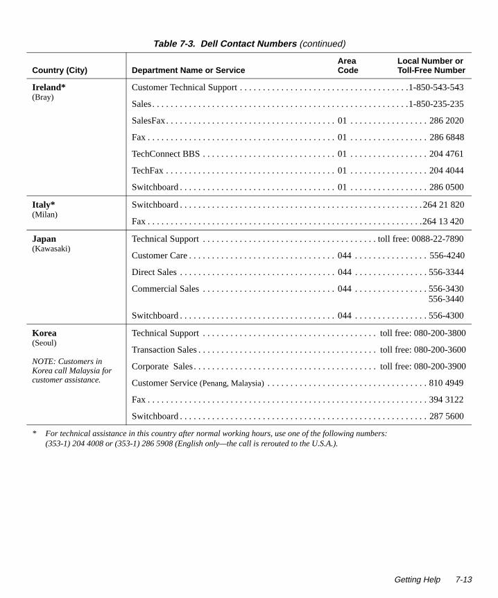
-543
-2
2020
68
761
044
500
820
890
4240
344
430
300
800
3600
3900
9
600
Ireland*(Bray)
Customer Technical Support . . . . . . . . . . . . . . . . . . . . . . . . . . . . . . . . . . . . .1-850-543
Sales. . . . . . . . . . . . . . . . . . . . . . . . . . . . . . . . . . . . . . . . . . . . . . . . . . . . . . . .1-850-23535
SalesFax. . . . . . . . . . . . . . . . . . . . . . . . . . . . . . . . . . . . . 01 . . . . . . . . . . . . . . . . . 286
Fax . . . . . . . . . . . . . . . . . . . . . . . . . . . . . . . . . . . . . . . . . 01 . . . . . . . . . . . . . . . . . 28648
TechConnect BBS . . . . . . . . . . . . . . . . . . . . . . . . . . . . . 01 . . . . . . . . . . . . . . . . . 204 4
TechFax . . . . . . . . . . . . . . . . . . . . . . . . . . . . . . . . . . . . . 01 . . . . . . . . . . . . . . . . . 204 4
Switchboard . . . . . . . . . . . . . . . . . . . . . . . . . . . . . . . . . . 01 . . . . . . . . . . . . . . . . . 286 0
Italy*(Milan)
Switchboard . . . . . . . . . . . . . . . . . . . . . . . . . . . . . . . . . . . . . . . . . . . . . . . . . . . . .264 21
Fax . . . . . . . . . . . . . . . . . . . . . . . . . . . . . . . . . . . . . . . . . . . . . . . . . . . . . . . . . . . .264 13420
Japan(Kawasaki)
Technical Support . . . . . . . . . . . . . . . . . . . . . . . . . . . . . . . . . . . . . . toll free: 0088-22-7
Customer Care . . . . . . . . . . . . . . . . . . . . . . . . . . . . . . . . 044 . . . . . . . . . . . . . . . . 556-
Direct Sales . . . . . . . . . . . . . . . . . . . . . . . . . . . . . . . . . . 044 . . . . . . . . . . . . . . . . 556-3
Commercial Sales . . . . . . . . . . . . . . . . . . . . . . . . . . . . . 044 . . . . . . . . . . . . . . . . 556-3556-3440
Switchboard . . . . . . . . . . . . . . . . . . . . . . . . . . . . . . . . . . 044 . . . . . . . . . . . . . . . . 556-4
Korea(Seoul)
NOTE: Customers in Korea call Malaysia for customer assistance.
Technical Support . . . . . . . . . . . . . . . . . . . . . . . . . . . . . . . . . . . . . . toll free: 080-200-3
Transaction Sales . . . . . . . . . . . . . . . . . . . . . . . . . . . . . . . . . . . . . . . toll free: 080-200-
Corporate Sales. . . . . . . . . . . . . . . . . . . . . . . . . . . . . . . . . . . . . . . . toll free: 080-200-
Customer Service (Penang, Malaysia) . . . . . . . . . . . . . . . . . . . . . . . . . . . . . . . . . . . 810 494
Fax . . . . . . . . . . . . . . . . . . . . . . . . . . . . . . . . . . . . . . . . . . . . . . . . . . . . . . . . . . . . . 394 3122
Switchboard . . . . . . . . . . . . . . . . . . . . . . . . . . . . . . . . . . . . . . . . . . . . . . . . . . . . . . 287 5
* For technical assistance in this country after normal working hours, use one of the following numbers:(353-1) 204 4008 or (353-1) 286 5908 (English only—the call is rerouted to the U.S.A.).
Table 7-3. Dell Contact Numbers (continued)
Country (City)Area Local Number or
Department Name or Service Code Toll-Free Number
Getting Help 7-13
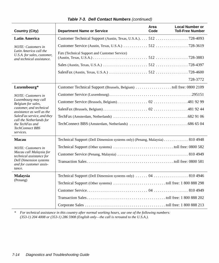
83
7
0
1
4
6
9
581
4949
202
213
Latin America
NOTE: Customers in Latin America call the U.S.A. for sales, customer, and technical assistance.
Customer Technical Support (Austin, Texas, U.S.A.). . . . 512 . . . . . . . . . . . . . . . . 728-4093
Customer Service (Austin, Texas, U.S.A.) . . . . . . . . . . . . 512 . . . . . . . . . . . . . . . . 728-3619
Fax (Technical Support and Customer Service) (Austin, Texas, U.S.A.) . . . . . . . . . . . . . . . . . . . . . . . . . . . 512 . . . . . . . . . . . . . . . . 728-38
Sales (Austin, Texas, U.S.A.) . . . . . . . . . . . . . . . . . . . . . . 512 . . . . . . . . . . . . . . . . 728-439
SalesFax (Austin, Texas, U.S.A.) . . . . . . . . . . . . . . . . . . . 512 . . . . . . . . . . . . . . . . 728-460
728-3772
Luxembourg*
NOTE: Customers in Luxembourg may call Belgium for sales, customer, and technical assistance as well as the SalesFax service, and they call the Netherlands for the TechFax and TechConnect BBS services.
Customer Technical Support (Brussels, Belgium) . . . . . . . . . . . . . . . . . . toll free: 0800 2109
Customer Service (Luxembourg). . . . . . . . . . . . . . . . . . . . . . . . . . . . . . . . . . . . . . . . .29515
Customer Service (Brussels, Belgium). . . . . . . . . . . . . . . 02 . . . . . . . . . . . . . . . . .481 92 99
SalesFax (Brussels, Belgium). . . . . . . . . . . . . . . . . . . . . . 02 . . . . . . . . . . . . . . . . .481 92 4
TechFax (Amsterdam, Netherlands) . . . . . . . . . . . . . . . . . . . . . . . . . . . . . . . . . . . . .682 91 0
TechConnect BBS (Amsterdam, Netherlands) . . . . . . . . . . . . . . . . . . . . . . . . . . . . .686 65 04
Macau
NOTE: Customers in Macau call Malaysia for technical assistance for Dell Dimension systems and for customer assis-tance.
Technical Support (Dell Dimension systems only) (Penang, Malaysia). . . . . . . . . . . . 810 4948
Technical Support (Other systems) . . . . . . . . . . . . . . . . . . . . . . . . . . . . . . toll free: 0800 582
Customer Service (Penang, Malaysia) . . . . . . . . . . . . . . . . . . . . . . . . . . . . . . . . . . . 810 494
Transaction Sales . . . . . . . . . . . . . . . . . . . . . . . . . . . . . . . . . . . . . . . . . . . toll free: 0800
Malaysia(Penang)
Technical Support (Dell Dimension systems only) . . . . . . 04 . . . . . . . . . . . . . . . . . 810 4946
Technical Support (Other systems) . . . . . . . . . . . . . . . . . . . . . . . . . . toll free: 1 800 888 298
Customer Service. . . . . . . . . . . . . . . . . . . . . . . . . . . . . . 04 . . . . . . . . . . . . . . . . . 810
Transaction Sales . . . . . . . . . . . . . . . . . . . . . . . . . . . . . . . . . . . . . . . toll free: 1 800 888
Corporate Sales . . . . . . . . . . . . . . . . . . . . . . . . . . . . . . . . . . . . . . . . toll free: 1 800 888
* For technical assistance in this country after normal working hours, use one of the following numbers:(353-1) 204 4008 or (353-1) 286 5908 (English only—the call is rerouted to the U.S.A.).
Table 7-3. Dell Contact Numbers (continued)
Country (City)Area Local Number or
Department Name or Service Code Toll-Free Number
7-14 Diagnostics and Troubleshooting Guide

85
86
870
78
878
800
838
663
171
8818
8003
504
5
617
56
56
0 00
898
Mexico(Colonia Granada)
NOTE: Customers in Mexico call the U.S.A. for access to the Automated Order-Status System and AutoTech.
Automated Order-Status System (Austin, Texas, U.S.A.) . . . . . . . . . . . . . . . . . . . . . . . . . . . 512 . . . . . . . . . . . . . . . . 728-06
AutoTech (Automated technical support)(Austin, Texas, U.S.A.) . . . . . . . . . . . . . . . . . . . . . . . . . . . 512 . . . . . . . . . . . . . . . . 728-06
Customer Technical Support . . . . . . . . . . . . . . . . . . . . . 525 . . . . . . . . . . . . . . . . 228-7
Sales. . . . . . . . . . . . . . . . . . . . . . . . . . . . . . . . . . . . . . . . 525 . . . . . . . . . . . . . . . . 228-11
toll free: 91-800-900-37
toll free: 91-800-904-49
Customer Service. . . . . . . . . . . . . . . . . . . . . . . . . . . . . . 525 . . . . . . . . . . . . . . . . 228-7
Main. . . . . . . . . . . . . . . . . . . . . . . . . . . . . . . . . . . . . . . . 525 . . . . . . . . . . . . . . . . 228-7
Netherlands*(Amsterdam)
Customer Technical Support . . . . . . . . . . . . . . . . . . . . . 020 . . . . . . . . . . . . . . . . .5818
Direct Sales . . . . . . . . . . . . . . . . . . . . . . . . . . . . . . . . . . . . . . . . . . . . . .toll free: 0800-0
Direct SalesFax . . . . . . . . . . . . . . . . . . . . . . . . . . . . . . . 020 . . . . . . . . . . . . . . . . 682 7
Corporate Sales . . . . . . . . . . . . . . . . . . . . . . . . . . . . . . . 020 . . . . . . . . . . . . . . . . 581
Corporate SalesFax . . . . . . . . . . . . . . . . . . . . . . . . . . . . 020 . . . . . . . . . . . . . . . . 686
TechConnect BBS . . . . . . . . . . . . . . . . . . . . . . . . . . . . . 020 . . . . . . . . . . . . . . . . 686 6
New Zealand Technical Support (Dell Dimension systems only) ($2.50 + GST per call). . . . . . . . . . . . . . . . . . . . . . . 0900 51010
Technical Support (Other systems) . . . . . . . . . . . . . . . . . . . . . . . . . . . . . . . . . .0800 446 25
Customer Service . . . . . . . . . . . . . . . . . . . . . . . . . . . . . . . . . . . . . . . . . . . . . .0800 444
Sales. . . . . . . . . . . . . . . . . . . . . . . . . . . . . . . . . . . . . . . . . . . . . . . . . . . . . . . . .0800 4417
Fax . . . . . . . . . . . . . . . . . . . . . . . . . . . . . . . . . . . . . . . . . . . . . . . . . . . . . . . . . .0800 4416
Norway*(Lysaker)
Customer Technical Support and Customer Service . . . . . . . . . . . . . . . . . . . . . 22-67 5
Sales. . . . . . . . . . . . . . . . . . . . . . . . . . . . . . . . . . . . . . . . . . . . . . . . . . . . . . . . . . .67-125 711
Poland*(Warsaw)
Switchboard . . . . . . . . . . . . . . . . . . . . . . . . . . . . . . . . . . . . . . . . . . . . . . . . . . . . . . 620-7
Fax . . . . . . . . . . . . . . . . . . . . . . . . . . . . . . . . . . . . . . . . . . . . . . . . . . . . . . . . . . . . . 620-4584
* For technical assistance in this country after normal working hours, use one of the following numbers:(353-1) 204 4008 or (353-1) 286 5908 (English only—the call is rerouted to the U.S.A.).
Table 7-3. Dell Contact Numbers (continued)
Country (City)Area Local Number or
Department Name or Service Code Toll-Free Number
Getting Help 7-15

9
054
053
700
710
49
0
30
0 80
3 53
185
2 00
199
169
591
185
Singapore(Singapore)
NOTE: Customers in Sin-gapore call Malaysia for technical assistance for Dell Dimension systems and for customer assis-tance.
Technical Support (Dell Dimension systems only) (Penang, Malaysia) . . . . . . . 04 . . . . . . . . . . . . . . . . . 810 4947
Technical Support (Other systems) . . . . . . . . . . . . . . . . . . . . . . . . . . toll free: 800 6011 051
Customer Service (Penang, Malaysia) . . . . . . . . . . . . . . . 04 . . . . . . . . . . . . . . . . . 810 494
Transaction Sales . . . . . . . . . . . . . . . . . . . . . . . . . . . . . . . . . . . . . . . toll free: 800 6011
Corporate Sales . . . . . . . . . . . . . . . . . . . . . . . . . . . . . . . . . . . . . . . . toll free: 800 6011
South Africa(Johannesburg)
Switchboard . . . . . . . . . . . . . . . . . . . . . . . . . . . . . . . . . . 011 . . . . . . . . . . . . . . . . 709 7
Technical Support . . . . . . . . . . . . . . . . . . . . . . . . . . . . . 011 . . . . . . . . . . . . . . . . 709 7
Fax . . . . . . . . . . . . . . . . . . . . . . . . . . . . . . . . . . . . . . . . . 011 . . . . . . . . . . . . . . . . 706 05
Southeast Asian/Pacific Countries(excluding Australia, Brunei, China, Hong Kong, Japan, Korea, Macau, Malaysia, New Zealand, Singapore, Taiwan, and Thailand—see individual listings for these countries)
Customer Technical Support, Customer Service, and Sales (Penang, Malaysia). . . . . . . . . . . . . . . . . . . . . . . . . . . . . . . . . . . . . . 60 4 810-481
Spain*(Madrid)
Technical Support . . . . . . . . . . . . . . . . . . . . . . . . . . . . . 91 . . . . . . . . . . . . . . .902 100 1
Customer Service. . . . . . . . . . . . . . . . . . . . . . . . . . . . . . 91 . . . . . . . . . . . . . . . . .329 1
TechConnect BBS . . . . . . . . . . . . . . . . . . . . . . . . . . . . . 91 . . . . . . . . . . . . . . . . .329 3
Sales. . . . . . . . . . . . . . . . . . . . . . . . . . . . . . . . . . . . . . . . 91 . . . . . . . . . . . . . . .902 100
Switchboard . . . . . . . . . . . . . . . . . . . . . . . . . . . . . . . . . . 91 . . . . . . . . . . . . . . . . .722 9
Sweden*(Upplands Vasby)
Technical Support . . . . . . . . . . . . . . . . . . . . . . . . . . . . . 08 . . . . . . . . . . . . . . . .590 05
Customer Care . . . . . . . . . . . . . . . . . . . . . . . . . . . . . . . . 08 . . . . . . . . . . . . . . . .590 05
TechConnect BBS . . . . . . . . . . . . . . . . . . . . . . . . . . . . . 08 . . . . . . . . . . . . . . . .590 05
Sales. . . . . . . . . . . . . . . . . . . . . . . . . . . . . . . . . . . . . . . . 08 . . . . . . . . . . . . . . . .590 05
* For technical assistance in this country after normal working hours, use one of the following numbers:(353-1) 204 4008 or (353-1) 286 5908 (English only—the call is rerouted to the U.S.A.).
Table 7-3. Dell Contact Numbers (continued)
Country (City)Area Local Number or
Department Name or Service Code Toll-Free Number
7-16 Diagnostics and Troubleshooting Guide

411
1 01
1 50
1 90
557
9
556
555
07
9
0 06
11
0110
3178
858
000
Switzerland*(Geneva)
Technical Support . . . . . . . . . . . . . . . . . . . . . . . . . . . . . . . . . . . . . . . . . . . . . . 0844 811
Commercial Services . . . . . . . . . . . . . . . . . . . . . . . . . . 022 . . . . . . . . . . . . . . . .799 0
Customer Service . . . . . . . . . . . . . . . . . . . . . . . . . . . . . 022 . . . . . . . . . . . . . . . .799 0
Fax . . . . . . . . . . . . . . . . . . . . . . . . . . . . . . . . . . . . . . . . . 022 . . . . . . . . . . . . . . . .799 0
Taiwan
NOTE: Customers in Tai-wan call Malaysia for cus-tomer assistance.
Technical Support . . . . . . . . . . . . . . . . . . . . . . . . . . . . toll free: 0080 651 226/0800 33
Customer Service (Penang, Malaysia) . . . . . . . . . . . . . . . . . . . . . . . . . . . . . . . . . . . 810 494
Transaction Sales . . . . . . . . . . . . . . . . . . . . . . . . . . . . . toll free: 0080 651 228/0800 33
Corporate Sales . . . . . . . . . . . . . . . . . . . . . . . . . . . . . . toll free: 0080 651 227/0800 33
Thailand
NOTE: Customers in Thailand call Malaysia for customer assistance.
Technical Support . . . . . . . . . . . . . . . . . . . . . . . . . . . . . . . . . . . . . . . toll free: 0880 060
Customer Service (Penang, Malaysia) . . . . . . . . . . . . . . . . . . . . . . . . . . . . . . . . . . . 810 494
Sales. . . . . . . . . . . . . . . . . . . . . . . . . . . . . . . . . . . . . . . . . . . . . . . . . . toll free: 0880 06
U.K.*(Bracknell)
Customer Technical Support(Dell Dimension systems) . . . . . . . . . . . . . . . . . . . . . . . . . 01344 . . . . . . . . . . . . . . . . 7201
Customer Technical Support (Other systems) . . . . . . . . . 01344 . . . . . . . . . . . . . . . .723723
Customer Care . . . . . . . . . . . . . . . . . . . . . . . . . . . . . . . . 01344 . . . . . . . . . . . . . . . .72
TechFax . . . . . . . . . . . . . . . . . . . . . . . . . . . . . . . . . . . . . 01344 . . . . . . . . . . . . . . . .72
TechConnect BBS . . . . . . . . . . . . . . . . . . . . . . . . . . . . . 01344 . . . . . . . . . . . . . . . .723
Sales. . . . . . . . . . . . . . . . . . . . . . . . . . . . . . . . . . . . . . . . 01344 . . . . . . . . . . . . . . . .720
* For technical assistance in this country after normal working hours, use one of the following numbers:(353-1) 204 4008 or (353-1) 286 5908 (English only—the call is rerouted to the U.S.A.).
Table 7-3. Dell Contact Numbers (continued)
Country (City)Area Local Number or
Department Name or Service Code Toll-Free Number
Getting Help 7-17

014
618
01
681
005
150
90
5
320
329
528
400
for
U.S.A.(Austin, Texas)
Automated Order-Status System . . . . . . . . . . . . . . . . . . . . . . . . . toll free: 1-800-433-9
AutoTech (Automated technical support). . . . . . . . . . . . . . . . . . . . . toll free: 1-800-247-9362
Customer Technical Support (Desktops)(Return Material Authorization Numbers—warranty repairs) . . . . . . . toll free: 1-800-624-9896
Customer Technical Support (Server Hotline)(Return Material Authorization Numbers—warranty repairs) . . . . . . . toll free: 1-800-967-1068
Dell Customer Service(Credit Return Authorization Numbers). . . . . . . . . . . . . . . . . . . . . . . toll free: 1-800-624-9897
Dell Sales . . . . . . . . . . . . . . . . . . . . . . . . . . . . . . . . . . . . . . . . . . . toll free: 1-800-247-4
DellWare® . . . . . . . . . . . . . . . . . . . . . . . . . . . . . . . . . . . . . . . . . . toll free: 1-800-753-72
DellWare FaxBack Service . . . . . . . . . . . . . . . . . . . . . . 512 . . . . . . . . . . . . . . . . 728-1
Fee-Based Technical Support . . . . . . . . . . . . . . . . . . . . . . . . . . . toll free: 1-800-433-9
Sales (Catalogs) . . . . . . . . . . . . . . . . . . . . . . . . . . . . . . . . . . . . . . toll free: 1-800-426-5
Spare Parts Sales:
Dell Direct1. . . . . . . . . . . . . . . . . . . . . . . . . . . . . . . . . . . . . . . toll free: 1-800-274-14
Major Accounts2. . . . . . . . . . . . . . . . . . . . . . . . . . . . . . . . . . . toll free: 1-800-357-335
Fax . . . . . . . . . . . . . . . . . . . . . . . . . . . . . . . . . . . . . . . . . . . . . . . . toll free: 1-800-727-8
TechFax . . . . . . . . . . . . . . . . . . . . . . . . . . . . . . . . . . . . . . . . . . . . toll free: 1-800-950-1
TechConnect BBS . . . . . . . . . . . . . . . . . . . . . . . . . . . . . 512 . . . . . . . . . . . . . . . . 728-8
Switchboard . . . . . . . . . . . . . . . . . . . . . . . . . . . . . . . . . . 512 . . . . . . . . . . . . . . . . 338-4
1 Use this telephone number if your call is about a system purchased for home, personal, or small-business use.2 Use this number if you are calling for an established Dell national account (have your account number handy), if you work a
governmental agency (local, state, or federal), or if you work for an educational or medical institution.
Table 7-3. Dell Contact Numbers (continued)
Country (City)Area Local Number or
Department Name or Service Code Toll-Free Number
7-18 Diagnostics and Troubleshooting Guide

Appendix ADiagnostic Video Tests
o
. the oes
bit s
ub-
e s e o
any
The Video Test Group of the Dell Diagnostics consists of the following seven tests, each of which verifies a par-ticular video function or group of functions:
• Video Memory Test — Checks the integrity of char-acters generated from data in the video memory
• Video Hardware Test — Checks the functions of the cursor register and the horizontal and vertical retrace bit registers
• Text Mode Character Test — Checks the video sub-system’s ability to present text mode data
• Text Mode Color Test — Checks the video sub-system’s ability to present color in text modes
• Text Mode Pages Test — Checks the video sub-system’s ability to map and present all available video text pages on the monitor screen, one page at a time
• Graphics Mode Test — Checks the video sub-system’s ability to present graphics mode data and colors
• Color Palettes Test — Checks the video subsystem’s ability to display all available colors
• Solid Colors Test — Checks the video subsystem’s ability to show screens full of solid colors. Allows you to check for missing color subpixels.
All of these tests, except the Video Memory Test and the Video Hardware Test, are interactive. These interactive tests display images on the monitor screen and require the user to respond with the following steps:
1. Examine a displayed image for correctness.
2. If an image is correct, type y.
3. If an image is incorrect, type n.
The following sections describe each of the tests in theVideo Test Group.
Video Memory TestThe Video Memory Test verifies the integrity of the video memory either on the system board or on a videexpansion card. As the test runs, it describes which 64-kilobyte (KB) block of video memory is being testedWhen a test is complete, a message indicates whethervideo memory has passed or failed the test. This test dnot require any interaction on your part.
Video Hardware TestThe Video Hardware Test verifies the operation of the cursor registers and the horizontal and vertical retrace registers. When a test is complete, a message indicatewhether these registers have passed or failed the test.This test does not require any interaction on your part.
Text Mode Character TestThe Text Mode Character Test consists of a group of stests that display printable characters and character attributes. The subtests check character quality and thmonitor’s ability to display the characters correctly on itscreen. A prompt at the bottom of each screen asks thuser to decide whether the display is satisfactory and trespond by typing y or n.
If you respond affirmatively to each subtest, the Text Mode Character Test passes. A negative response to subtest causes the test to fail.
Diagnostic Video Tests A-1

The following subsections describe the subtests of the Text Mode Character Test in the order in which they appear.
Character Attributes Subtest (80 x 25)The 80-column x 25-line character attributes subtest dis-plays four lines of text that demonstrate normal-intensity
video, reverse video, intensified video, and blinking video. Figure A-1 shows an example of the 80-column x 25-line character attributes subtest screen.
Figure A-1. 80-Column x 25-Line Character Attributes Subtest Screen
Is this correct - Y/N?
Character Attributes Test (80 x 25)
A-2 Diagnostics and Troubleshooting Guide

by 25-line text mode. Figure A-2 shows an example ofthe character set subtest screen.
Figure A-2. 80-Column x 25-Line Character Set Subtest Screen
Is this correct - Y/N?
Character Set Test (80 x 25)
Diagnostic Video Tests A-3
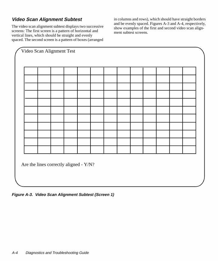
rs ly,
n-
Video Scan Alignment SubtestThe video scan alignment subtest displays two successive screens: The first screen is a pattern of horizontal and vertical lines, which should be straight and evenly spaced. The second screen is a pattern of boxes (arranged
in columns and rows), which should have straight bordeand be evenly spaced. Figures A-3 and A-4, respectiveshow examples of the first and second video scan aligment subtest screens.
Figure A-3. Video Scan Alignment Subtest (Screen 1)
Are the lines correctly aligned - Y/N?
Video Scan Alignment Test
A-4 Diagnostics and Troubleshooting Guide

Figure A-4. Video Scan Alignment Subtest (Screen 2)
Are the boxes correctly aligned - Y/N?
Video Scan Alignment Test
Diagnostic Video Tests A-5

, e .
Character Attributes Subtest (40 x 25)The 40-column x 25-line character attributes subtest displays four lines of text in 40-column by 25-line (double-wide) text mode that demonstrate
normal-intensity video, reverse video, intensified videoand blinking video. Figure A-5 shows an example of th40-column x 25-line character attributes subtest screen
Figure A-5. 40-Column x 25-Line Character Attributes Subtest Screen
Is this correct - Y/N?
Character Attributes Test (40 x 25)
A-6 Diagnostics and Troubleshooting Guide

Character Set Subtest (40 x 25)The 40-column x 25-line character set subtest displays all 256 characters in the ASCII character set in 40-column by 25-line (double-wide) text mode. Figure A-6 shows an example of the 40-column x 25-line character set subtest screen.
Figure A-6. 40-Column x 25-Line Character Set Subtest Screen
Is this correct - Y/N?
Character Set Test (40 x 25)
Diagnostic Video Tests A-7

Text Mode Color TestThe Text Mode Color Test contains three subtests that check the video subsystem’s ability to present color in text modes. The following subsections describe these subtests.
NOTE: These subtests are valid for color monitors only.
Color Attributes Subtest (80 x 25)The 80-column x 25-line color attributes subtest displays a pattern of 16 rows and 16 columns in 80-column by 25-line text mode. Each row has a hexadecimal number in a unique foreground color and each column has a unique background color. Where the same foreground and background color intersect, the hexadecimal number is not visible. Type y if each character is displayed cor-rectly; otherwise, type n. Table A-1 indicates the color in each of the rows and columns.
Table A-1. Color Attributes
Row or ColumnNumber
ForegroundColor
BackgroundColor
0 black black
1 blue blue
2 green green
3 cyan cyan
4 red red
5 magenta magenta
6 brown brown
7 white white
8 dark gray* black
9 light blue* blue
A light green* green
B light cyan* cyan
C light red* red
D light magenta* magenta
E yellow* brown
F intense white* white
* These colors blink during the test.
A-8 Diagnostics and Troubleshooting Guide

m’s ys nti-
is-
Color Attributes Subtest (40 x 25)The 40-column x 25-line color attributes subtest is the same as the previous subtest except that the characters are displayed in 40-column by 25-line (double-wide) text mode. Type y if each character is displayed correctly; otherwise, type n.
Color Bars SubtestThe color bars subtest displays 16 bars in different colors with background intensity enabled. Under each bar is the name of the color that should be displayed. Type y if each color bar is displayed correctly; otherwise, type n.
Text Mode Pages TestThe Text Mode Pages Test checks the video subsysteability to map and present all available video pages onthe monitor screen, one page at a time. The test displaeight successive screens, the first of which contains 21lines of 77 zeros. The remaining seven screens are idecal to the first, except that each screen substitutes a different numeral (1 through 7) for the zeros.
Type y if all the rows of numbers on each screen are dplayed correctly; otherwise, type n. Figure A-7 shows an example of the first of these screens.
Figure A-7. Text Mode Pages Test Screen
Is this video page correct - Y/N?
Video Text Pages Test 0
Diagnostic Video Tests A-9

en an,
n ray
Graphics Mode TestThe Graphics Mode Test checks the video subsystem’s ability to present graphics mode data and colors. This test displays nine different screens, each of which allows you to check some aspect of graphics mode data and colors. The following subsections describe Graphics Mode Test screens in the order in which they appear.
NOTE: Some of the following tests may not appear if your system does not support the video mode being tested.
320 x 200 Graphics Mode ScreensThe Graphics Mode Test displays two successive 320- x 200-pixel graphics mode screens: The first scredisplays three pyramids in red, green, and yellow. Thesecond screen displays three pyramids in magenta, cyand white. Type y if all the pyramids are the correct colors; otherwise, type n.
640 x 200 Black/White Graphics Mode ScreenThe 640- x 200-pixel black/white graphics mode screedisplays a black rectangle and a white rectangle on a gbackground. Type y if the boxes are displayed correctly;otherwise, type n. Figure A-8 shows an example of this screen.
A-10 Diagnostics and Troubleshooting Guide

Figure A-8. 640 x 200 Black/White Graphics Mode Screen
Is this correct - Y/N?
640 x 200 Graphics - Black/White
Diagnostic Video Tests A-11

640 x 480 Monochrome Graphics Mode ScreenThe 640- x 480-pixel monochrome graphics mode screen displays three chess pieces. Type y if all the chess pieces
are identical and displayed correctly; otherwise, type n. Figure A-9 shows an example of this screen.
Figure A-9. 640 x 480 Monochrome Graphics Mode Screen
Is this correct - Y/N?
640 x 480 Graphics - Monochrome
A-12 Diagnostics and Troubleshooting Guide

is-e pe
-
320 x 200 16-Color Graphics Mode ScreenThe 320- x 200-pixel 16-color graphics mode screen dis-plays a series of Xs in 16 different colors with the name of the color beneath each X. Type y if all the Xs are the correct colors; otherwise, type n.
640 x 200 16-Color Graphics Mode ScreenThe 640- x 200-pixel 16-color graphics mode screen dis-plays a series of hexagons in 16 different colors with the name of the color beneath each hexagon. Type y if all the hexagons are the correct colors; otherwise, type n.
640 x 350 16-Color Graphics Mode ScreenThe 640- x 350-pixel 16-color graphics mode screen dplays a series of octagons in 16 different colors with thname of the color displayed beneath each octagon. Tyy if all the octagons are the correct colors; otherwise, type n.
640 x 480 2-Color Graphics Mode ScreenThe 640- x 480-pixel 2-color graphics mode screen displays three chess pieces. Type y if all the chess pieces areidentical and displayed correctly; otherwise, type n. Fig-ure A-10 shows an example of this screen.
Diagnostic Video Tests A-13

Figure A-10. 640 x 480 2-Color Graphics Mode Screen
Is this correct - Y/N?
640 x 480 Graphics - 2 Colors
A-14 Diagnostics and Troubleshooting Guide

ed
r-
for
de
-
f
x n,
ch
se se
640 x 480 16-Color Graphics Mode ScreenThe 640- x 480-pixel 16-color graphics mode screen dis-plays a series of stars in 16 different colors with the name of the color beneath each star. Type y if all the stars are the correct colors; otherwise, type n.
320 x 200 256-Color Graphics Mode ScreenThe 320- x 200-pixel 256-color graphics mode screen displays a series of squares in 256 different color hues and intensities. Type y if all the squares are the correct colors; otherwise, type n.
640 x 480 256-Color Graphics Mode ScreenThe 640- x 480-pixel 256-color graphics mode screen displays a series of squares with two colors in each square. Type y if all the squares appear to be correct; oth-erwise, type n.
800 x 600 16-Color Graphics Mode ScreenThe 800- x 600-pixel 16-color graphics mode screen dis-plays a series of pyramids in 16 different colors. Type y if all the pyramids appear to be correct; otherwise, type n.
800 x 600 256-Color Graphics Mode ScreenThe 800- x 600-pixel 256-color graphics mode screen displays a series of squares with four colors in each square. Type y if all the squares appear to be correct; oth-erwise, type n.
1024 x 768 16-Color Graphics Mode ScreenThe 1024- x 768-pixel 16-color graphics mode screen displays a series of hourglasses in 16 different colors. Type y if all the hourglasses appear to be correct; other-wise, type n.
1024 x 768 256-Color Graphics Mode ScreenThe 1024- x 768-pixel 256-color graphics mode screendisplays a series of asterisks with four colors in each asterisk. Type y if all the asterisks appear to be correct;otherwise, type n.
1280 x 1024 16-Color Graphics Mode ScreenThe 1280- x 1024-pixel 16-color graphics mode screendisplays a series of squares in 16 different colors locatin various positions on the screen. Type y if all the squares appear to be correct; otherwise, type n.
Color Palettes TestThe Color Palettes Test checks the video subsystem’sability to display all available colors. The test displays two screens that allow you to check the quality of diffeent shades of the basic colors and to test the monitor’sability to vary the intensity of these colors.
The first screen contains four sets of 64 squares, one gray and one for each of the three basic colors (red, green, and blue). Each square contains a different shaof its associated color, ranging from very light to very dark. Type y if all the squares are the correct colors; otherwise type n.
The second screen is the red/green/blue (RGB) color combination screen. This screen allows you to test themonitor’s ability to increase or decrease the intensity othe three basic colors.
The RGB color combination screen displays an RGB boin the top center of the screen with individual red, greeand blue boxes beneath it. Underneath the individual color boxes are three lines that show the intensity of eacolor. Type r , g, or b to adjust the intensity of the corre-sponding color; then press the right-arrow key to increathe color intensity, or press the left-arrow key to decreathe intensity. The RGB box should be able to display 262,144 different colors when you adjust the intensity levels of red, green, and blue. Type y if all the squares are the correct colors; otherwise type n.
Diagnostic Video Tests A-15
sat-
Solid Colors Test The Solid Colors Test checks whether the video sub-system is displaying the correct colors. This test also lets you check for missing pixels. When this test is running, four screens appear sequentially—a red screen, a green screen, a blue screen, and a white screen. Check each screen for missing pixels, and verify that the correct color is being displayed.When the test is complete, a message asks if you are isfied with the quality of the colors. Type y if all the pixels were present and if the correct colors were dis-played; otherwise, type n.
A-16 Diagnostics and Troubleshooting Guide

Abbreviations and Acronyms
Abbreviationor Acronym Description
A ampere(s)
AC alternating current
ADC analog-to-digital converter
ADI Autodesk Device Interface
AI artificial intelligence
ANSI American National Standards Institute
ASCII American Standard Code for Information Interchange
ASIC application-specific integrated circuit
BASIC Beginner’s All-Purpose Symbolic Instruction Code
BBS bulletin board service
BIOS basic input/output system
bpi bits per inch
bps bits per second
BTU British thermal unit
BZT Bundesamt fur Zulassungen in der Telekommunikation
C Celsius
CCFT cold cathode fluorescent tube
CD compact disc
CD-ROM compact disc read-only memory
CGA color graphics adapter
cm centimeter(s)
CMOS complementary metal-oxide semiconductor
C.O.D. collect on delivery
cpi characters per inch
cpl characters per line
CPU central processing unit
DAC digital-to-analog converter
DASH Dell Advanced SCSI Host
DAT digital audio tape
dB decibel(s)
dBA adjusted decibel(s)
DC direct current
DIN Deutsche Industrie Norm
DIP dual in-line package
DMA direct memory access
DOC Department of Communications (in Canada)
dpi dots per inch
Abbreviationor Acronym Description
Abbreviations and Acronyms 1

DRAM dynamic random-access memory
DS/DD double-sided double-density
DS/HD double-sided high-density
DSA Dell SCSI Array
ECC error correction code
EGA enhanced graphics adapter
EIDE enhanced integrated drive electronics
EISA Extended Industry-Standard Architecture
EMI electromagnetic interference
EMM expanded memory manager
EMS Expanded Memory Specification
EPP Enhanced Parallel Port
EPROM erasable programmable read-only memory
ESD electrostatic discharge
ESDI enhanced small-device interface
ESM embedded server management
F Fahrenheit
FAT file allocation table
FCC Federal Communications Commission
FIFO first-in first-out
ft feet
g gram(s)
G gravities
GB gigabyte(s)
Abbreviationor Acronym Description
GUI graphical user interface
h hexadecimal
HMA high memory area
HPFS High Performance File System
Hz hertz
I/O input/output
ID identification
IDE integrated drive electronics
IR infrared
IRQ interrupt request
ISA Industry-Standard Architecture
JEIDA Japanese Electronic Industry Development Association
K kilo- (1024)
KB kilobyte(s)
KB/sec kilobyte(s) per second
Kbit(s) kilobit(s)
Kbit(s)/sec kilobit(s) per second
kg kilogram(s)
kHz kilohertz
LAN local area network
lb pound(s)
LCD liquid crystal display
LED light-emitting diode
LIF low insertion force
LN load number
LIM Lotus/Intel/Microsoft
Abbreviationor Acronym Description
2 Diagnostics and Troubleshooting Guide

lpi lines per inch
m meter(s)
mA milliampere(s)
mAh milliampere-hour(s)
MB megabyte(s)
MBR master boot record
MDA monochrome display adapter
MGA monochrome graphics adapter
MHz megahertz
mm millimeter(s)
ms millisecond(s)
MS-DOS Microsoft Disk Operating System
MTBF mean time between failures
mV millivolt(s)
NIC network interface controller
NiCad nickel cadmium
NiMH nickel-metal hydride
NMI nonmaskable interrupt
ns nanosecond(s)
NTFS NT File System
NVRAM nonvolatile random-access memory
OS/2 Operating System/2
OTP one-time programmable
PAL programmable array logic
PCI Peripheral Component Interconnect
Abbreviationor Acronym Description
PCMCIA Personal Computer Memory Card International Association
PGA pin grid array
POST power-on self-test
ppm pages per minute
PQFP plastic quad flat pack
PS/2 Personal System/2
PVC polyvinyl chloride
QIC quarter-inch cartridge
RAM random-access memory
RAMDAC random-access memory digital-to-analog converter
REN ringer equivalence number
RFI radio frequency interference
RGB red/green/blue
ROM read-only memory
rpm revolutions per minute
RTC real-time clock
SCSI small computer system interface
sec second(s)
SIMM single in-line memory module
SRAM static random-access memory
SVGA super video graphics array
TFT thin film transistor
tpi tracks per inch
TSR terminate-and-stay-resident
TV television
Abbreviationor Acronym Description
Abbreviations and Acronyms 3

UL Underwriters Laboratories
UMB upper memory block
UPS uninterruptible power supply
USB universal serial bus
USOC Universal Service Ordering Code
V volt(s)
VAC volt(s) alternating current
VDC volt(s) direct current
VDE Verband Deutscher Elektrotechniker
VESA Video Electronics Standards Association
VGA video graphics array
VLSI very-large-scale integration
VRAM video random-access memory
W watt(s)
WH watt-hour(s)
XMM extended memory manager
XMS eXtended Memory Specification
ZIF zero insertion force
Abbreviationor Acronym Description
4 Diagnostics and Troubleshooting Guide

Index
AAbout
Main menu category, 4-8
assistancetechnical, 7-1telephone numbers, 7-8warranty repair or credit, 7-5
assistance, technicalobtaining, 7-1
Audio Test Group, 4-21, 4-22
AutoTech service, 7-3
Bbattery
troubleshooting, 6-3
beep codesabout, 2-9system, 2-10
boot routine, 1-1
bulletin board service. See TechConnect BBS
Ccalling Dell, 7-8
cautions, viii
Color Palettes Test, A-1, A-15
computer coverremoving and replacing, 6-1
connections and switchestroubleshooting, 1-2
DDell Diagnostics
about, 2-1, 4-1diskette, 4-1list of tests, 4-9starting, 4-2video tests, A-1video tests, about, A-1
Dell Q&A, 7-3
device drivers, 3-3
diagnosing problems, 7-1
Diagnostics Checklist, 7-7
diagnostics diskette, 4-1
Diskette Drives Test Group, 4-16
diskette/tape drive subsystemtroubleshooting, about, 6-9troubleshooting, single diskette-drive system, 6-9verifying proper operation, 6-9
diskettesdata corrupted or lost, 4-16problems with, 4-16
Index 1

EEISA Configuration Utility, 1-4
electrostatic discharge. See ESD
EMM driver, 3-2
ESD, vi, 6-2
expanded memoryabout, 3-2EMM driver, 3-2
expansion cardstroubleshooting, 6-4
extended memoryabout, 3-2conversion to expanded memory, 3-2
Ffailures
technical assistance, 7-1
fixing problems, 7-1
Frequently Asked Questions cards, 7-3
Ggetting help, 7-1
graphics mode screens, A-10
Graphics Mode Test, A-1, A-10
grounding procedure, 6-1
Hhard-disk drives
diagnostics tests, 4-17IDE CD ROM Drives Test Group, 4-17
hard-disk drives (continued)SCSI Devices Test Group, 4-20troubleshooting IDE hard-disk drives, 6-14troubleshooting SCSI drives, 6-15, 6-17
Hard-Disk Drives (Non-SCSI) Test Group, 4-16
helpfrom Dell Computer Corporation, 7-1
help toolsAutoTech service, 7-3Dell Diagnostics program, 7-3Dell Q&A, 7-3Frequently Asked Questions cards, 7-3system documentation, 7-3TechConnect BBS, 7-4TechFax service, 7-4
II, 6-12
I/O functions, 5-3
I/O ports, 5-2
IDE CD ROM Drives Test Group, 4-17
IDE hard-disk drives, troubleshooting, 6-14
interruptsavoiding assignment conflicts, 3-3
IRQ lines, 3-3
Kkeyboard
troubleshooting, 5-2
Keyboard Test Group, 4-15
Key-Help, 4-8
2 Diagnostics and Troubleshooting Guide
MMain menu categories, 4-5, 4-6, 4-8
math coprocessorSystem Set Test Group, 4-13testing, 4-13
memorychecking for address conflicts, 3-3conventional, 3-1expanded, 3-1extended, 3-1RAM Test Group, 4-12troubleshooting, 6-5
messagesabout, 2-1beep codes, system, 2-1, 2-9Dell Diagnostics, 4-12error messages, 3-2system, 2-1warning, 2-13
monitor, troubleshooting, 5-1
Mouse Test, 4-15
NNetwork Interface Test Group, 4-21
nonvolatile random-access memory, 2-13
notational conventions, viii
notes, viii
NVRAMabout, 4-4problem with accessing, 2-9
OOptions
Main menu category, 4-6
Other Test Group, 4-22
PParallel Ports Test Group, 4-19
parallel printertroubleshooting, 5-4
parity errors, 4-12
peripheralserratic behavior, 4-18, 4-19
portsfailure to recognize, 4-18, 4-19Parallel Ports Test Group, 4-19Serial/Infrared Ports Test Group, 4-18
power sourcetroubleshooting, 1-2
problemshelp tools, 7-1technical assistance, 7-1with your order, 7-5
problem-solving procedures, 5-4
product information, 7-5
QQuit
Main menu category, 4-8
Index 3

y,
RRAM, 4-20
RAM Test Group, 4-12
returns, 7-5
RunMain menu category, 4-5
Ssafety instructions
for preventing ESD, vigeneral, v
safety precautionsfor preventing electrostatic discharge, 6-1
screen, 5-4
SCSI Devices Test Group, 4-20
SelectMain menu category, 4-5
serial I/O devicestroubleshooting, 5-4
Serial/Infrared Ports Test Group, 4-18
service, 7-1
SI, 6-11
single diskette-drive system, 6-9
softwareanalyzing problems, 3-1apparent malfunction, 4-12checking for viruses, 3-1device drivers, 3-3does not recognize a port, 4-19, 4-20error messages, 3-2errors, troubleshooting, 3-1input errors, 3-2installing and configuring, 3-1memory-resident programs, 3-2
software (continued)problems, 3-1program conflicts, 3-3spreadsheet or mathematical program running slowl
4-14system start-up files, 3-1using, 3-2
Solid Colors Test, A-16
SubtestMain menu category, 4-5
supporttechnical, 7-1
syntax errors, 4-16
system beep codeslist of, 2-10
system boardtroubleshooting, 6-8
system configuration informationabout, 4-4confirming with Dell Diagnostics, 4-4
system documentation, 7-3
system memorytroubleshooting, 6-5
system messagesabout, 2-1solving problems indicated by, 2-1
System Set Test Group, 4-12
System Setup program, 1-4
Ttape drives, 6-11
TechConnect BBS, 7-4
TechFax service, 7-4
4 Diagnostics and Troubleshooting Guide

technical assistanceobtaining, 7-1warranty repair or credit, 7-5
Test LimitsMain menu category, 4-8
Text Mode Character Test, A-1
Text Mode Color Test, A-1, A-8
Text Mode Pages Test, A-1, A-9
troubleshootingaudible signs of problems, 1-3basic problems, 1-1battery, 6-3checking connections and switches, 1-2Diagnostics Checklist, 7-7diskette drives, 6-9diskette/tape drive subsystem, 6-9dropped or damaged computer, 6-2expansion cards, 6-4hard-disk drives, 6-14I/O functions, 5-3I/O ports, 5-2keyboard, 5-2monitor, 5-1parallel printer, 5-4SCSI hard-disk drives, 6-15, 6-17serial I/O devices, 5-4single diskette-drive system, 6-9software errors, 3-1system board, 6-8system memory, 6-5tape drives, 6-9, 6-11, 6-12video subsystem, 6-6visual signs of problems, 1-3wet computer, 6-2where to start, 1-1
TSR programsabout, 3-1problems with, 3-2
typographical conventions, viii
Vvideo control circuitry, 4-14
video controller card, 4-14
video functionsabout, A-1testing, 4-14
Video Hardware Test, A-1
Video Memory Test, A-1
video subsystemtroubleshooting, 6-6
Video Test Group, 4-14
video testsColor Palettes, A-1, A-15Graphics Mode, A-1, A-10Solid Colors Test, A-1, A-16Text Mode Character, A-1, A-6Text Mode Color, A-1, A-8, A-9Text Mode Pages, A-1, A-9Video Hardware, A-1Video Memory, A-1
Wwarning messages, 2-13
warnings, viii
warranty information, vii
warranty repair or credit, 7-5
water damage, 6-2
working inside your computer, safety precautions, 6-1
Index 5