option un7 - user's and programming guide, …nagui/labequip/synth/manuals/e...bit error rate...
TRANSCRIPT

User’s and Programming Guide
Agilent Technologies
ESG Family Signal Generators
Option UN7 Bit Error Rate Test
Part No. E4400-90331
Printed in USAApril 2000
Supersedes: August 1999
© Copyright 1999, 2000 Agilent Technologies

ii
Contents
1. The Bit Error Rate TestOverview . . . . . . . . . . . . . . . . . . . . . . . . . . . . . . . . . . . . . . . . . . . . . . . . . . . . . . . . . . . . . . . . . . .1-2Verifying Bit Error Rate Test Operation. . . . . . . . . . . . . . . . . . . . . . . . . . . . . . . . . . . . . . . . . .1-3
Operator’s Check . . . . . . . . . . . . . . . . . . . . . . . . . . . . . . . . . . . . . . . . . . . . . . . . . . . . . . . . . . .1-3
2. Using FunctionsSetting Up a Bit Error Rate Test on a PHS radio . . . . . . . . . . . . . . . . . . . . . . . . . . . . . . . . . .2-2
Making the Cable Connections. . . . . . . . . . . . . . . . . . . . . . . . . . . . . . . . . . . . . . . . . . . . . . . .2-2Setting the Carrier Frequency and Power Level. . . . . . . . . . . . . . . . . . . . . . . . . . . . . . . . . .2-3Selecting the Radio Data Format . . . . . . . . . . . . . . . . . . . . . . . . . . . . . . . . . . . . . . . . . . . . . .2-4Setting the Radio to a Receiver Mode . . . . . . . . . . . . . . . . . . . . . . . . . . . . . . . . . . . . . . . . . .2-4Selecting the BERT Data Pattern, Maximum Data Rate, and Total Bits . . . . . . . . . . . . . .2-4Selecting the BERT Trigger . . . . . . . . . . . . . . . . . . . . . . . . . . . . . . . . . . . . . . . . . . . . . . . . . .2-5Starting BERT measurements . . . . . . . . . . . . . . . . . . . . . . . . . . . . . . . . . . . . . . . . . . . . . . . .2-5
3. ReferenceSoftkey Reference . . . . . . . . . . . . . . . . . . . . . . . . . . . . . . . . . . . . . . . . . . . . . . . . . . . . . . . . . . . .3-2
Mode Key . . . . . . . . . . . . . . . . . . . . . . . . . . . . . . . . . . . . . . . . . . . . . . . . . . . . . . . . . . . . . . . . .3-2BERT . . . . . . . . . . . . . . . . . . . . . . . . . . . . . . . . . . . . . . . . . . . . . . . . . . . . . . . . . . . . . . . . . . . .3-2BERT Off On . . . . . . . . . . . . . . . . . . . . . . . . . . . . . . . . . . . . . . . . . . . . . . . . . . . . . . . . . . . . . .3-2BERT Resync Off On. . . . . . . . . . . . . . . . . . . . . . . . . . . . . . . . . . . . . . . . . . . . . . . . . . . . . . . .3-3BERT Trigger . . . . . . . . . . . . . . . . . . . . . . . . . . . . . . . . . . . . . . . . . . . . . . . . . . . . . . . . . . . . .3-3Bus . . . . . . . . . . . . . . . . . . . . . . . . . . . . . . . . . . . . . . . . . . . . . . . . . . . . . . . . . . . . . . . . . . . . . .3-3Clock Gate Off On . . . . . . . . . . . . . . . . . . . . . . . . . . . . . . . . . . . . . . . . . . . . . . . . . . . . . . . . . .3-3Clock Gate Polarity Neg Pos. . . . . . . . . . . . . . . . . . . . . . . . . . . . . . . . . . . . . . . . . . . . . . . . . .3-3Clock Polarity Neg Pos . . . . . . . . . . . . . . . . . . . . . . . . . . . . . . . . . . . . . . . . . . . . . . . . . . . . . .3-4Configure BERT . . . . . . . . . . . . . . . . . . . . . . . . . . . . . . . . . . . . . . . . . . . . . . . . . . . . . . . . . . .3-4Configure Trigger . . . . . . . . . . . . . . . . . . . . . . . . . . . . . . . . . . . . . . . . . . . . . . . . . . . . . . . . . .3-4Cycle Count . . . . . . . . . . . . . . . . . . . . . . . . . . . . . . . . . . . . . . . . . . . . . . . . . . . . . . . . . . . . . . .3-4Cycle End. . . . . . . . . . . . . . . . . . . . . . . . . . . . . . . . . . . . . . . . . . . . . . . . . . . . . . . . . . . . . . . . .3-5Data . . . . . . . . . . . . . . . . . . . . . . . . . . . . . . . . . . . . . . . . . . . . . . . . . . . . . . . . . . . . . . . . . . . . .3-5Data Polarity Neg Pos. . . . . . . . . . . . . . . . . . . . . . . . . . . . . . . . . . . . . . . . . . . . . . . . . . . . . . .3-5Delayed Bits . . . . . . . . . . . . . . . . . . . . . . . . . . . . . . . . . . . . . . . . . . . . . . . . . . . . . . . . . . . . . .3-5Display BER % Exp. . . . . . . . . . . . . . . . . . . . . . . . . . . . . . . . . . . . . . . . . . . . . . . . . . . . . . . . .3-6Display Update Cycle End Cont. . . . . . . . . . . . . . . . . . . . . . . . . . . . . . . . . . . . . . . . . . . . . . .3-6Ext . . . . . . . . . . . . . . . . . . . . . . . . . . . . . . . . . . . . . . . . . . . . . . . . . . . . . . . . . . . . . . . . . . . . . .3-6Fail Hold . . . . . . . . . . . . . . . . . . . . . . . . . . . . . . . . . . . . . . . . . . . . . . . . . . . . . . . . . . . . . . . . .3-6Immediate . . . . . . . . . . . . . . . . . . . . . . . . . . . . . . . . . . . . . . . . . . . . . . . . . . . . . . . . . . . . . . . .3-6Impedance 75 Ohm TTL . . . . . . . . . . . . . . . . . . . . . . . . . . . . . . . . . . . . . . . . . . . . . . . . . . . . .3-7Max. Data Rate 2Mbps 10Mbps . . . . . . . . . . . . . . . . . . . . . . . . . . . . . . . . . . . . . . . . . . . . . . .3-7Pass/Fail Limits. . . . . . . . . . . . . . . . . . . . . . . . . . . . . . . . . . . . . . . . . . . . . . . . . . . . . . . . . . . .3-7Pass/Fail Off On . . . . . . . . . . . . . . . . . . . . . . . . . . . . . . . . . . . . . . . . . . . . . . . . . . . . . . . . . . .3-7Pass/Fail Update . . . . . . . . . . . . . . . . . . . . . . . . . . . . . . . . . . . . . . . . . . . . . . . . . . . . . . . . . . .3-8PN9 . . . . . . . . . . . . . . . . . . . . . . . . . . . . . . . . . . . . . . . . . . . . . . . . . . . . . . . . . . . . . . . . . . . . .3-8PN15 . . . . . . . . . . . . . . . . . . . . . . . . . . . . . . . . . . . . . . . . . . . . . . . . . . . . . . . . . . . . . . . . . . . .3-8Resync Limits . . . . . . . . . . . . . . . . . . . . . . . . . . . . . . . . . . . . . . . . . . . . . . . . . . . . . . . . . . . . .3-8Special Pattern 0’s 1’s . . . . . . . . . . . . . . . . . . . . . . . . . . . . . . . . . . . . . . . . . . . . . . . . . . . . . . .3-9Special Pattern Ignore Off On . . . . . . . . . . . . . . . . . . . . . . . . . . . . . . . . . . . . . . . . . . . . . . . .3-9Total Bits . . . . . . . . . . . . . . . . . . . . . . . . . . . . . . . . . . . . . . . . . . . . . . . . . . . . . . . . . . . . . . . . .3-9Trigger Key . . . . . . . . . . . . . . . . . . . . . . . . . . . . . . . . . . . . . . . . . . . . . . . . . . . . . . . . . . . . . . .3-9
iii

Contents
Display Annotation . . . . . . . . . . . . . . . . . . . . . . . . . . . . . . . . . . . . . . . . . . . . . . . . . . . . . . . . . 3-101. Setting Information . . . . . . . . . . . . . . . . . . . . . . . . . . . . . . . . . . . . . . . . . . . . . . . . . . . . . 3-102. Measurement Results . . . . . . . . . . . . . . . . . . . . . . . . . . . . . . . . . . . . . . . . . . . . . . . . . . . 3-123. Other Information . . . . . . . . . . . . . . . . . . . . . . . . . . . . . . . . . . . . . . . . . . . . . . . . . . . . . . 3-12
Rear Panel Overview . . . . . . . . . . . . . . . . . . . . . . . . . . . . . . . . . . . . . . . . . . . . . . . . . . . . . . . . 3-131. BER DATA IN Connector. . . . . . . . . . . . . . . . . . . . . . . . . . . . . . . . . . . . . . . . . . . . . . . . . 3-132. BER CLK IN Connector . . . . . . . . . . . . . . . . . . . . . . . . . . . . . . . . . . . . . . . . . . . . . . . . . . 3-133. BER GATE IN Connector . . . . . . . . . . . . . . . . . . . . . . . . . . . . . . . . . . . . . . . . . . . . . . . . 3-134. BER MEAS END Connector . . . . . . . . . . . . . . . . . . . . . . . . . . . . . . . . . . . . . . . . . . . . . . 3-135. BER TEST OUT Connector . . . . . . . . . . . . . . . . . . . . . . . . . . . . . . . . . . . . . . . . . . . . . . . 3-146. BER ERR OUT Connector . . . . . . . . . . . . . . . . . . . . . . . . . . . . . . . . . . . . . . . . . . . . . . . . 3-147. BER NO DATA Connector . . . . . . . . . . . . . . . . . . . . . . . . . . . . . . . . . . . . . . . . . . . . . . . . 3-148. BER SYNC LOSS Connector . . . . . . . . . . . . . . . . . . . . . . . . . . . . . . . . . . . . . . . . . . . . . . 3-14
4. OperationTesting Signal Definitions. . . . . . . . . . . . . . . . . . . . . . . . . . . . . . . . . . . . . . . . . . . . . . . . . . . . . 4-2Functional Differences between Max. Data Rate 2 Mbps and 10 Mbps. . . . . . . . . . . . . . . . . 4-3Data Processing . . . . . . . . . . . . . . . . . . . . . . . . . . . . . . . . . . . . . . . . . . . . . . . . . . . . . . . . . . . . . 4-4
Special Pattern Ignore Function . . . . . . . . . . . . . . . . . . . . . . . . . . . . . . . . . . . . . . . . . . . . . . 4-4Pass/Fail Judgement . . . . . . . . . . . . . . . . . . . . . . . . . . . . . . . . . . . . . . . . . . . . . . . . . . . . . . . 4-4Synchronization . . . . . . . . . . . . . . . . . . . . . . . . . . . . . . . . . . . . . . . . . . . . . . . . . . . . . . . . . . . 4-4
Repeat Measurements. . . . . . . . . . . . . . . . . . . . . . . . . . . . . . . . . . . . . . . . . . . . . . . . . . . . . . . . 4-5Clock Gate Function . . . . . . . . . . . . . . . . . . . . . . . . . . . . . . . . . . . . . . . . . . . . . . . . . . . . . . . . . 4-6
5. Remote Programming:CALCulate Subsystem SCPI Command Reference . . . . . . . . . . . . . . . . . . . . . . . . . . . . . . . . 5-2
BER Display Mode . . . . . . . . . . . . . . . . . . . . . . . . . . . . . . . . . . . . . . . . . . . . . . . . . . . . . . . . . 5-2BER Display Update Mode . . . . . . . . . . . . . . . . . . . . . . . . . . . . . . . . . . . . . . . . . . . . . . . . . . 5-2BER Pass/Fail Judgement Mode . . . . . . . . . . . . . . . . . . . . . . . . . . . . . . . . . . . . . . . . . . . . . . 5-2BER Pass/Fail Limits . . . . . . . . . . . . . . . . . . . . . . . . . . . . . . . . . . . . . . . . . . . . . . . . . . . . . . . 5-3BER Pass/Fail State . . . . . . . . . . . . . . . . . . . . . . . . . . . . . . . . . . . . . . . . . . . . . . . . . . . . . . . . 5-3
:DATA Subsystem SCPI Command Reference. . . . . . . . . . . . . . . . . . . . . . . . . . . . . . . . . . . . . 5-4BER Measurement Result Query . . . . . . . . . . . . . . . . . . . . . . . . . . . . . . . . . . . . . . . . . . . . . 5-4
:INPut Subsystem SCPI Command Reference . . . . . . . . . . . . . . . . . . . . . . . . . . . . . . . . . . . . 5-5BER Clock Gate Polarity . . . . . . . . . . . . . . . . . . . . . . . . . . . . . . . . . . . . . . . . . . . . . . . . . . . . 5-5BER Clock Gate State . . . . . . . . . . . . . . . . . . . . . . . . . . . . . . . . . . . . . . . . . . . . . . . . . . . . . . 5-5BER Clock Polarity. . . . . . . . . . . . . . . . . . . . . . . . . . . . . . . . . . . . . . . . . . . . . . . . . . . . . . . . . 5-5BER Data Polarity . . . . . . . . . . . . . . . . . . . . . . . . . . . . . . . . . . . . . . . . . . . . . . . . . . . . . . . . . 5-5BER Input Impedance . . . . . . . . . . . . . . . . . . . . . . . . . . . . . . . . . . . . . . . . . . . . . . . . . . . . . . 5-6
:SENSe Subsystem SCPI Command Reference . . . . . . . . . . . . . . . . . . . . . . . . . . . . . . . . . . . . 5-7BER Cycle Count . . . . . . . . . . . . . . . . . . . . . . . . . . . . . . . . . . . . . . . . . . . . . . . . . . . . . . . . . . 5-7BER Data Pattern . . . . . . . . . . . . . . . . . . . . . . . . . . . . . . . . . . . . . . . . . . . . . . . . . . . . . . . . . 5-7BER Maximum Data Rate . . . . . . . . . . . . . . . . . . . . . . . . . . . . . . . . . . . . . . . . . . . . . . . . . . . 5-7BER Resync Limits . . . . . . . . . . . . . . . . . . . . . . . . . . . . . . . . . . . . . . . . . . . . . . . . . . . . . . . . 5-7BER Resynchronization State . . . . . . . . . . . . . . . . . . . . . . . . . . . . . . . . . . . . . . . . . . . . . . . . 5-8BER Special Pattern Ignore Data . . . . . . . . . . . . . . . . . . . . . . . . . . . . . . . . . . . . . . . . . . . . . 5-8BER Special Pattern Ignore State. . . . . . . . . . . . . . . . . . . . . . . . . . . . . . . . . . . . . . . . . . . . . 5-8BER Total Bits . . . . . . . . . . . . . . . . . . . . . . . . . . . . . . . . . . . . . . . . . . . . . . . . . . . . . . . . . . . . 5-8
iv

Contents
BER Trigger Bit Delay . . . . . . . . . . . . . . . . . . . . . . . . . . . . . . . . . . . . . . . . . . . . . . . . . . . . . .5-9BER Trigger Bit Delay State . . . . . . . . . . . . . . . . . . . . . . . . . . . . . . . . . . . . . . . . . . . . . . . . .5-9BER Trigger Source . . . . . . . . . . . . . . . . . . . . . . . . . . . . . . . . . . . . . . . . . . . . . . . . . . . . . . . .5-9BERT State . . . . . . . . . . . . . . . . . . . . . . . . . . . . . . . . . . . . . . . . . . . . . . . . . . . . . . . . . . . . . . .5-9
:STATus Subsystem SCPI Command Reference . . . . . . . . . . . . . . . . . . . . . . . . . . . . . . . . . .5-10Status Preset . . . . . . . . . . . . . . . . . . . . . . . . . . . . . . . . . . . . . . . . . . . . . . . . . . . . . . . . . . . . .5-10Data Questionable BERT Status Group Condition Register Query . . . . . . . . . . . . . . . . .5-10Data Questionable BERT Status Group Enable . . . . . . . . . . . . . . . . . . . . . . . . . . . . . . . . .5-10Data Questionable BERT Status Group Event Register Query. . . . . . . . . . . . . . . . . . . . .5-10Data Questionable BERT Status Negative Transition Filter Register Enable . . . . . . . . .5-11Data Questionable BERT Status Positive Transition Filter Register Enable. . . . . . . . . .5-11
:TRIGger Subsystem SCPI Command Reference . . . . . . . . . . . . . . . . . . . . . . . . . . . . . . . . . .5-12Abort . . . . . . . . . . . . . . . . . . . . . . . . . . . . . . . . . . . . . . . . . . . . . . . . . . . . . . . . . . . . . . . . . . .5-12
6. Programming Command Cross-Reference
7. Programming ExamplesTesting Bit Error Rate on a PHS radio . . . . . . . . . . . . . . . . . . . . . . . . . . . . . . . . . . . . . . . . . . .7-2
Program Comments . . . . . . . . . . . . . . . . . . . . . . . . . . . . . . . . . . . . . . . . . . . . . . . . . . . . . . . .7-3
v

Contents
vi
ESG Family Signal GeneratorsOption UN7
1 The Bit Error Rate Test
This guide describes features specific to the bit error rate test (BERT) capability of theAgilent Technologies ESG Family Signal Generator with Option UN7.
Bit Error Rate Test User’s and Programming Guide 1-1
The Bit Error Rate Test ESG Family Signal GeneratorsOverview Option UN7
OverviewThe bit error rate test (BERT) function allows you to test the bit error rate (BER) of digitalcommunications equipment, such as sensitivity and selectivity of receivers or components.
This document contains the following chapters:
Chapter 1, “The Bit Error Rate Test,” briefly explains the contents of this document.
Chapter 2, “Using Functions,” shows an example of typical operating procedures to makea BER measurement on a radio.
Chapter 3, “Reference,” describes the principal operation of the softkeys, displayannotation, and the rear panel connectors which are implemented for the BERT function.
Chapter 4, “Operation,” explains some unique BERT features which might be beneficial tousers.
Chapter 5, “Remote Programming,” contains a brief overview of the Standard Commandsof Programmable Instruments (SCPI) programming language and an alphabetical listingof all of the SCPI commands which are implemented for the BER measurement function.
Chapter 6, “Programming Command Cross-Reference,” lists all of the BERT softkeys andtheir corresponding SCPI commands.
Chapter 7, “Programming Examples,” shows a list of the programming statements tomake a typical BER measurement on a radio.
This guide is only for Option UN7. Refer to the user's guide and/or programming guide forthe ESG Family Signal Generator for general functions such as setting the frequency andamplitude of the RF output.
NOTE One of the I/Q baseband generator options is required to operate Option UN7.This manual documents use with Option UN8.
1-2 Bit Error Rate Test User’s and Programming Guide
ESG Family Signal Generators The Bit Error Rate TestOption UN7 Verifying Bit Error Rate Test Operation
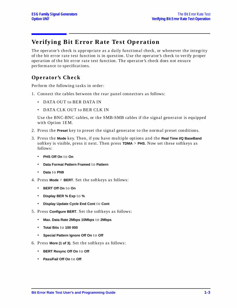
Verifying Bit Error Rate Test OperationThe operator’s check is appropriate as a daily functional check, or whenever the integrityof the bit error rate test function is in question. Use the operator’s check to verify properoperation of the bit error rate test function. The operator’s check does not ensureperformance to specifications.
Operator’s CheckPerform the following tasks in order:
1. Connect the cables between the rear panel connectors as follows:
• DATA OUT to BER DATA IN
• DATA CLK OUT to BER CLK IN
Use the BNC-BNC cables, or the SMB-SMB cables if the signal generator is equippedwith Option 1EM.
2. Press the Preset key to preset the signal generator to the normal preset conditions.
3. Press the Mode key. Then, if you have multiple options and the Real Time I/Q BaseBandsoftkey is visible, press it next. Then press TDMA > PHS. Now set these softkeys asfollows:
• PHS Off On to On
• Data Format Pattern Framed to Pattern
• Data to PN9
4. Press Mode > BERT. Set the softkeys as follows:
• BERT Off On to On
• Display BER % Exp to %
• Display Update Cycle End Cont to Cont
5. Press Configure BERT . Set the softkeys as follows:
• Max. Data Rate 2Mbps 10Mbps to 2Mbps
• Total Bits to 100 000
• Special Pattern Ignore Off On to Off
6. Press More (1 of 3) . Set the softkeys as follows:
• BERT Resync Off On to Off
• Pass/Fail Off On to Off
Bit Error Rate Test User’s and Programming Guide 1-3

The Bit Error Rate Test ESG Family Signal GeneratorsVerifying Bit Error Rate Test Operation Option UN7
7. Press More (2 of 3) . Set the softkeys as follows:
• Clock Polarity Pos Neg to Neg
• Data Polarity Pos Neg to Pos
• Clock Gate Off On to Off
• Impedance 75 Ohm TTL to TTL
8. Press Return > Configure Trigger . Set the softkeys as follows:
• BERT Trigger to Immediate
• Cycle Cont to 0
• Bit Delay Off On to Off
9. You will see the following results on the display:
10.Disconnect the cable between the DATA OUT connector and the BER DATA INconnector. Notice the No Data annunciator on the lower left corner of the display. Thisannunciator turns off when you reconnect the cable.
11.Disconnect the cable between the DATA CLK OUT connector and the BER CLK INconnector. Notice the No Clock annunciator on the lower left corner of the display. Thisannunciator turns off when you reconnect the cable, and the BER result is almost 50%.
Press the Return key and toggle the BERT Off On softkey to Off and then to On. You will seethe new BER result is the same as shown in the table above.
12.Press Configure BERT > More (1 of 3) > More (2 of 3) . Toggle the Clock Gate Off On softkey to Onand the Clock Gate Polarity Pos Neg softkey to Pos . You will see the same display as shownin the table above.
Change Clock Gate Polarity Pos Neg to Neg and you will see Sync Loss and No Clock on thelower left corner of the display.
Connect a short connector to the rear panel BER GATE IN connector and you willobserve a new BER measurement is being done.
Total Bits Error Bits BER
0 to 100,000 bits 0 bits 0.00000000%
(counting up) (always) (always)
1-4 Bit Error Rate Test User’s and Programming Guide
ESG Family Signal GeneratorsOption UN7
2 Using Functions
This chapter contains procedures to show you how to use some of the major functions ofthe Bit Error Rate Test (BERT).
Bit Error Rate Test User’s and Programming Guide 2-1
Using Functions ESG Family Signal GeneratorsSetting Up a Bit Error Rate Test on a PHS radio Option UN7
Setting Up a Bit Error Rate Test on a PHS radioUse this procedure to make BER measurements on a PHS radio with theAgilent Technologies ESG-D and ESG-DP Series Signal Generator with Option UN7. Thissection explains each of the following objectives:
• making the cable connections
• setting the carrier frequency and the power level
• selecting the PHS data format
• setting the PHS radio to a receiver mode
• selecting the BERT data pattern to PN9, maximum data rate to 2 Mbps, and total bitsto 100,000
• selecting the BERT trigger
• starting the BERT measurements
Making the Cable Connections
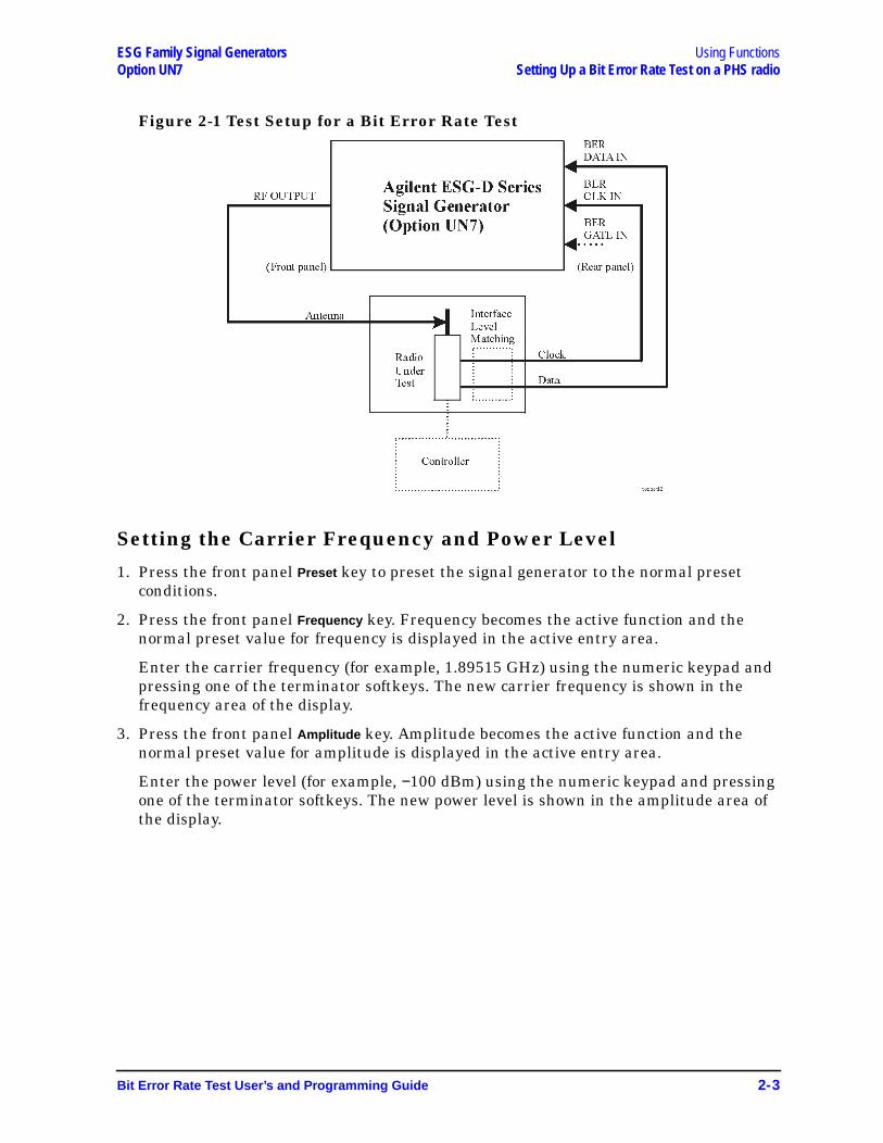
1. Connect the cables between your radio and the ESG-D and ESG-DP Series SignalGenerator with Option UN7 as follows:
An external controller will be required to control the radio under test. An interface levelmatching circuit will be required for interfacing between the radio under test and theESG-D and ESG-DP Series Signal Generator with Option UN7, when the radio signalspecifications are different from those of the signal generator.
ESG-D and ESG-DP SeriesSignal Generator Option UN71
1. In this example, the BER GATE IN connector is not used.
Radio
RF signal: RF OUTPUT connector (front panel2)
2. Rear panel, when the signal generator is equipped with Option 1EM.
Antenna Input port
Data signal: BER DATA IN connector (rear panel) Data Output port
Clock signal: BER CLK IN connector (rear panel) Clock Output port
2-2 Bit Error Rate Test User’s and Programming Guide
ESG Family Signal Generators Using FunctionsOption UN7 Setting Up a Bit Error Rate Test on a PHS radio
Figure 2-1 Test Setup for a Bit Error Rate Test
Setting the Carrier Frequency and Power Level
1. Press the front panel Preset key to preset the signal generator to the normal presetconditions.
2. Press the front panel Frequency key. Frequency becomes the active function and thenormal preset value for frequency is displayed in the active entry area.
Enter the carrier frequency (for example, 1.89515 GHz) using the numeric keypad andpressing one of the terminator softkeys. The new carrier frequency is shown in thefrequency area of the display.
3. Press the front panel Amplitude key. Amplitude becomes the active function and thenormal preset value for amplitude is displayed in the active entry area.
Enter the power level (for example, −100 dBm) using the numeric keypad and pressingone of the terminator softkeys. The new power level is shown in the amplitude area ofthe display.
Bit Error Rate Test User’s and Programming Guide 2-3
Using Functions ESG Family Signal GeneratorsSetting Up a Bit Error Rate Test on a PHS radio Option UN7
Selecting the Radio Data Format
1. Press the front panel Mode key. Then, if you have multiple options and the Real Time I/QBaseBand softkey is visible, press it next. Then press TDMA and the PHS softkey to selectthe PHS communications standard.
2. Toggle the Data Format Pattern Framed softkey to Framed . When you select Framed forbursting the frame envelope, you will be transmitting framed data. This means that youwill be bursting the timeslots that you have activated and there will be no RF carrierduring the off timeslots. Notice that the Configure Timeslots softkey has become an activesoftkey.
3. Observe the display and notice that the normal preset condition for downlink timeslot#1 has the timeslot turned on and configured as a traffic channel (TCH). Press theConfigure Timeslots softkey and look at the softkeys. The Timeslot # softkey shows thatdownlink timeslot #1 is selected as the active timeslot. The Timeslot Off On softkey showsthat downlink timeslot #1 is turned on. The Timeslot Type softkey shows that downlinktimeslot #1 is configured as a traffic channel. Press the Configure TCH softkey. The Datasoftkey shows that PN9 is selected as a data pattern.
4. Press the front panel Return key to move up the softkey menus until the first PHS menuis displayed. (The first softkey in this menu is PHS Off On .) Press the PHS Off On softkey totoggle the PHS format from Off to On. At this time the internal baseband generator willgenerate the internal data patterns that you have configured for Downlink timeslot 1and Uplink timeslot 1. A message is displayed while this process is taking place. Notice,also, that the PHS, I/Q , and ENVLP display annunciators are turned on.
5. Press the front panel RF On/Off key to toggle RF on. Notice that the display annunciatorchanges from RF OFF to RF ON. The modulated signal is now available at the RFOUTPUT connector.
Setting the Radio to a Receiver ModeSet the PHS radio to receive the signal of the specified carrier frequency and thetimeslot 1, and output the data used for the bit error rate measurements.
Selecting the BERT Data Pattern, Maximum Data Rate, andTotal Bits
1. Press the Mode key and then press the BERT softkey to configure parameters for makingBER measurements.
2. Press the Configure BERT softkey and look at the softkeys. The Data softkey shows thatPN9 is selected as the data pattern. The Max. Data Rate 2Mbps 10Mbps softkey shows thatthe maximum data rate is set to 2 Mbps mode.
3. Press the Total Bits softkey and enter 100,000 in this entry field using the numerickeypad and pressing Bits terminator softkey.
2-4 Bit Error Rate Test User’s and Programming Guide
ESG Family Signal Generators Using FunctionsOption UN7 Setting Up a Bit Error Rate Test on a PHS radio
Selecting the BERT Trigger
1. Press the Return key once to move up one level of softkey menus until the first BERTmenu is displayed. (The first softkey in this menu is BERT Off On .)
2. Press the Configure Trigger softkey to reveal the next menu.
3. Notice that the Trigger Key is active in the BERT Trigger softkey as the default setting.
4. Press the Return key once to move up one level of softkey menus until the first BERTmenu is displayed. (The first softkey in this menu is BERT Off On .) Press the BERT Off Onsoftkey. The BERT toggles from Off to On.
Starting BERT measurements
1. Press the front panel Trigger key for starting a BER measurement. You will see themeasurement result values of the Total Bits, Error Bits, and BER on the display.
NOTE If you encounter difficulty making a BER measurement, check the following:
• Make sure that the cable connections are properly configured.
• Make sure the data pattern for the BER measurement, specified by theData softkey, matches the data pattern in the traffic channel (TCH) for theRF signal being input to the radio under test.
• Make sure RF is turned on.
• Make sure the amplitude is set to the correct level.
• Make sure if the radio under test is controlled to receive the signal of thespecified carrier frequency and the timeslot.
Bit Error Rate Test User’s and Programming Guide 2-5

Using Functions ESG Family Signal GeneratorsSetting Up a Bit Error Rate Test on a PHS radio Option UN7
2-6 Bit Error Rate Test User’s and Programming Guide
ESG Family Signal GeneratorsOption UN7
3 Reference
This chapter contains descriptions for each softkey, the display annotations, and the rearpanel connectors that are specific to your Agilent Technologies ESG Family SignalGenerator with Option UN7.
For information and guidance on how to operate these functions remotely, see Chapter 5,“Remote Programming” and Chapter 6, “Programming Command Cross-Reference.”
Bit Error Rate Test User’s and Programming Guide 3-1
Reference ESG Family Signal GeneratorsSoftkey Reference Option UN7
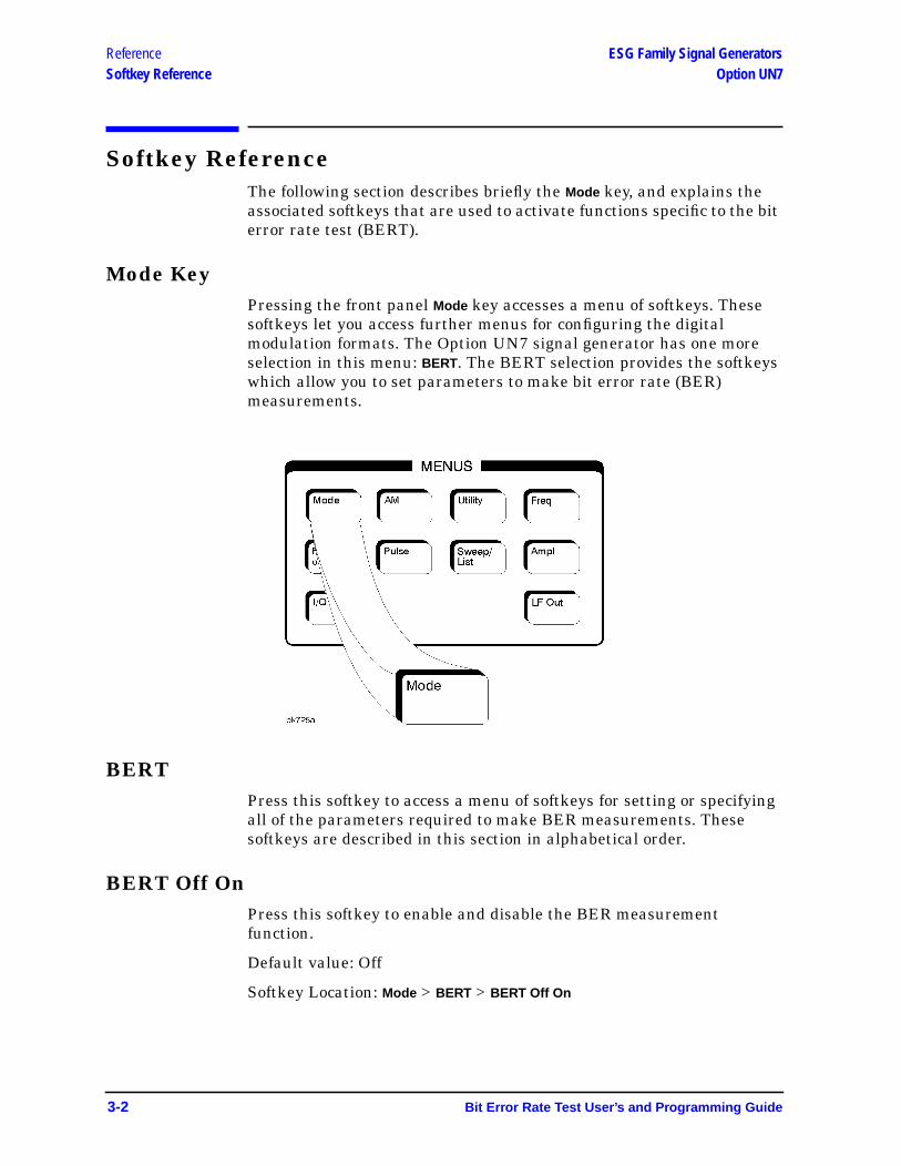
Softkey ReferenceThe following section describes briefly the Mode key, and explains theassociated softkeys that are used to activate functions specific to the biterror rate test (BERT).
Mode KeyPressing the front panel Mode key accesses a menu of softkeys. Thesesoftkeys let you access further menus for configuring the digitalmodulation formats. The Option UN7 signal generator has one moreselection in this menu: BERT. The BERT selection provides the softkeyswhich allow you to set parameters to make bit error rate (BER)measurements.
BERTPress this softkey to access a menu of softkeys for setting or specifyingall of the parameters required to make BER measurements. Thesesoftkeys are described in this section in alphabetical order.
BERT Off OnPress this softkey to enable and disable the BER measurementfunction.
Default value: Off
Softkey Location: Mode > BERT > BERT Off On
3-2 Bit Error Rate Test User’s and Programming Guide
ESG Family Signal Generators ReferenceOption UN7 Softkey Reference
BERT Resync Off OnSets the operating state of the resynchronizing function. This softkey isvalid only when the Max. Data Rate 2Mbps 10Mbps softkey is already set to2Mbps . When you select On, a new BER measurement will immediatelybe restarted whenever the previous BER measurement result exceedsthe value specified by the Resync Limits softkey.
Default value: On
Softkey Location: Mode > BERT > Configure BERT > Max. Data Rate 2Mbps >BERT Resync Off On
BERT TriggerAccesses a menu of choices for triggering BER measurements. You canchoose triggering that occurs immediately (Immediate ), triggering by thefront panel Trigger key (Trigger Key ), triggering that is supplied by theGPIB (Bus ), or triggering on the positive edge of a signal supplied to theTRIGGER IN connector (Ext).
Softkey Location: Mode > BERT > Configure Trigger > BERT Trigger
BusThis softkey is one of the choices in the BERT Trigger menu. With Busselected, use the *TRG GPIB command to trigger BER measurements.
Default value: BERT trigger is set to Trigger Key
Softkey Location: Mode > BERT > Configure Trigger > BERT Trigger > Bus
Clock Gate Off OnToggles the clock gate function off and on. When you select On, the clocksignal is valid when the clock gate signal is high for the normal(positive) mode, or low for the inverted (negative) mode. This clock gatesignal is connected to the rear panel BER GATE IN connector.
Default value: Off
Softkey Location: Mode > BERT > Configure BERT > Clock Gate Off On
Clock Gate Polarity Neg PosInputs polarity of the clock gate signal supplied to the rear panel BERGATE IN connector. When you select Pos (positive), the clock signal isvalid when the clock gate signal is high; when you select Neg (negative),the clock signal is valid when the clock gate signal is low.
Default value: Pos (Positive)
Softkey Location: Mode > BERT > Configure BERT > Clock Gate On >Clock Gate Polarity Neg Pos
Bit Error Rate Test User’s and Programming Guide 3-3
Reference ESG Family Signal GeneratorsSoftkey Reference Option UN7
Clock Polarity Neg PosInputs polarity of the clock signal supplied to the rear panel BER CLKIN connector. When you select Pos (positive), the rising edge is used;when you select Neg (negative), the falling edge is used.
Default value: Pos (Positive)
Softkey Location: Mode > BERT > Configure BERT >Clock Polarity Neg Pos
Configure BERTAccesses more menus for configuring test parameters for BERmeasurements.
Softkey Location: Mode > BERT > Configure BERT
Configure TriggerAccesses more menus for configuring trigger parameters for BERmeasurements.
Softkey Location: Mode > BERT > Configure Trigger
Cycle CountSpecifies the number of repetitions of BER measurements. The range ofthe acceptable values is from 0 to 65,535. With 0 set, the BERmeasurements are repeated till you set the BERT Off On softkey to Off .Enter the value using the numeric keypad and terminate it by pressingthe Enter softkey.
Default value: 1
Softkey Location: Mode > BERT > Configure Trigger > Cycle Count
3-4 Bit Error Rate Test User’s and Programming Guide
ESG Family Signal Generators ReferenceOption UN7 Softkey Reference
Cycle EndThis softkey is one of the choices in the Pass/Fail Update menu. WithCycle End selected, a pass or fail judgement is made for each BERmeasurement result.
Default value: Pass/Fail Update mode is Cycle End
Softkey Location: Mode > BERT > Configure BERT > Pass/Fail On >Pass/Fail Update > Cycle End
DataPress this softkey to access a menu of choices for the incoming datapattern to the BER DATA IN connector with either PN9 or PN15.
NOTE Be sure to match this value to the data pattern in the traffic channel(TCH) of the RF signal which is input to the radio under test.
Default value: PN9
Softkey Location: Mode > BERT > Configure BERT > Data
Data Polarity Neg PosPress this softkey to set the input polarity of the data signal supplied tothe rear panel BER DATA IN connector. When you select Pos (positive),the data signal is used as it is; when you select Neg (negative), thepolarity of the data signal is inverted.
Default value: Pos (Positive)
Softkey Location: Mode > BERT > Configure BERT > Data Polarity Pos Neg
Delayed BitsPress this softkey to specify the number of delay bits from the triggerevent for starting BER measurements. This softkey is valid only whenthe BERT Trigger Bit Delay softkey is set to On. The acceptable range ofvalues is from 0 to 65,535. Enter the value using the numeric keypadand terminate it by pressing the Enter softkey.
Default value: 0
Softkey Location: Mode > BERT > Configure Trigger > Bit Delay On >Delayed Bits
Bit Error Rate Test User’s and Programming Guide 3-5

Reference ESG Family Signal GeneratorsSoftkey Reference Option UN7
Display BER % ExpSets the display mode for BER measurement results. When you select%, the BER measurement results are displayed in percent. When youselect Exp , the BER measurement results are displayed in theexponential format of n.nnnnnE-mm.
Default value: %
Softkey Location: Mode > BERT > Display BER % Exp
Display Update Cycle End ContDisplays update mode during BER measurements. When you selectCycle End , the previous BER measurement result is displayed during thecurrent measurement cycle. When you select Cont , the display shows itsreal-time intermediate results during each BER measurement. Thissoftkey is valid only when the Max. Data Rate 2Mbps 10Mbps softkey is setto 2Mbps .
Default value: Cycle End
Softkey Location: Mode > BERT > Display Update Cycle End Cont
ExtWith Ext selected, BER measurements are made by the external triggersignal supplied to the rear panel TRIGGER IN connector.
Default value: BERT trigger is set to Trigger Key
Softkey Location: Mode > BERT > Configure Trigger > BERT Trigger > Ext
Fail HoldThis softkey is one of the choices in the Pass/Fail Update menu. WithFail Hold selected, the fail judgement is made once fail has been foundduring one loop of BER repeat measurements.
Default value: Pass/Fail Update mode is set to Cycle End
Softkey Location: Mode > BERT > Configure BERT > Pass/Fail On >Pass/Fail Update > Fail Hold
ImmediateThis softkey is one of the choices in the BERT Trigger menu. WithImmediate selected, BER measurements are initiated and repeated untilyou set the BERT Off On softkey to Off or until you set the BERT Triggersoftkey to Trigger Key , Bus , or Ext .
Default value: BERT trigger is set to Trigger Key
Softkey Location: Mode > BERT > Configure Trigger > BERT Trigger >Immediate
3-6 Bit Error Rate Test User’s and Programming Guide

ESG Family Signal Generators ReferenceOption UN7 Softkey Reference
Impedance 75 Ohm TTLSets the input termination mode of the rear panel BER DATA IN, BERCLK IN, and BER GATE IN connectors.
Default value: TTL
Softkey Location: Mode > BERT > Configure BERT > Impedance 75 Ohm TTL
Max. Data Rate 2Mbps 10MbpsSets the maximum data bit rate mode of BER measurements. Whenyou select 2Mbps , all of the functions can be activated for BERmeasurements. When you select 10Mbps , the resynchronization andspecial pattern ignore functions are not available, and you can not setthe Display Update Cycle End Cont softkey to Cont .
Default value: 2Mbps
Softkey Location: Mode > BERT > Configure BERT >Max. Data Rate 2Mbps 10Mbps
Pass/Fail LimitsSpecifies the threshold level of the comparator function. The range ofthe variable is from 0.0000001 (0.1ppm) to 1.0000000 (100%). Enter thevalue using the numeric keypad and terminate it by pressing the % orppm softkey.
Default value: 0.0100000 (1%)
Softkey Location: Mode > BERT > Configure BERT > Pass/Fail On >Pass/Fail Limits
Pass/Fail Off OnToggles the pass/fail judgement function off and on. The pass/failjudgement function compares a BER measurement result with thethreshold level defined by the Pass/Fail Limits softkey, and judges whetherthat BER measurement result has passed or failed.
Default value: Off
Softkey Location: Mode > BERT > Configure BERT > Pass/Fail Off On
Bit Error Rate Test User’s and Programming Guide 3-7
Reference ESG Family Signal GeneratorsSoftkey Reference Option UN7
Pass/Fail UpdateAccesses the pass/fail judgement update mode menu. With Cycle Endselected, either pass or fail judgement is made for each BERmeasurement result. With Fail Hold selected, the fail judgement is madeonce fail has been found during one loop of BER repeat measurements.
Default value: Cycle End
Softkey Location: Mode > BERT > Configure BERT > Pass/Fail On >Pass/Fail Update
PN9This softkey is one of the choices in the Data Select menu. With PN9selected, the incoming data to the BER DATA IN connector is assumedto be PN9 data.
Default value: Data is set to PN9
Softkey Location: Mode > BERT > Configure BERT > Data > PN9
PN15This softkey is one of the choices in the Data Select menu. With PN15selected, the incoming data to the BER DATA IN connector is assumedto be PN15 data.
Default value: Data is set to PN9
Softkey Location: Mode > BERT > Configure BERT > Data > PN15
Resync LimitsPress this softkey to specify the threshold level for resynchronizingBER measurements. This softkey is valid only when the Max. Data Rate2Mbps 10Mbps softkey is set to 2Mbps and the BERT Resync Off On softkey isset to On. The acceptable range of values is from 0.0500 to 0.4000. Enterthe value using the numeric keypad and terminate it by pressing the %or ppm softkey.
Default value: 0.4000
Softkey Location: Mode > BERT > Configure BERT > Max. Data Rate 2Mbps >BERT Resync On > Resync Limits
3-8 Bit Error Rate Test User’s and Programming Guide
ESG Family Signal Generators ReferenceOption UN7 Softkey Reference
Special Pattern 0’s 1’sPress this softkey to set the parameter of the special pattern ignorefunction. With 0’s selected, more than 80 bits of 0’s are ignored whenthey are detected. With 1’s selected, more than 80 bits of 1’s are ignoredwhen they are detected. This softkey is valid only when the Max. DataRate 2Mbps 10Mbps softkey is set to 2Mbps and theSpecial Pattern Ignore Off On softkey is set to On.
Default value: 0’s
Softkey Location: Mode > BERT > Configure BERT > Max. Data Rate 2Mbps >Special Pattern Ignore On > Special Pattern 0’s 1’s
Special Pattern Ignore Off OnPress this softkey to set the operating state of the special pattern ignorefunction. This function detects more than 80 bits of 0’s or 1’s in theincoming bit stream and ignores these bits during BER measurements.This softkey is valid only when the Max. Data Rate 2Mbps 10Mbps softkey isset to 2Mbps .
Default value: Off
Softkey Location: Mode > BERT > Configure BERT > Max. Data Rate 2Mbps >Special Pattern Ignore Off On
Total BitsPress this softkey to specify the total bit count to be measured for onemeasurement cycle. The acceptable range of values is from 100 to4,294,967,295. Enter the value using the numeric keypad andterminate the value by pressing the Bits , KBits , 10KBits , 100KBits , MBits ,10MBits , or 100MBits softkey.
Default value: 10,000
Softkey Location: Mode > BERT > Configure BERT > Total Bits
Trigger KeyThis softkey is one of the choices in the BERT Trigger menu. WithTrigger Key selected, BER measurements are made by pressing the frontpanel Trigger key.
Default value: BERT trigger is set to Trigger Key
Softkey Location: Mode > BERT > Configure Trigger > BERT Trigger >Trigger Key
Bit Error Rate Test User’s and Programming Guide 3-9
Reference ESG Family Signal GeneratorsDisplay Annotation Option UN7
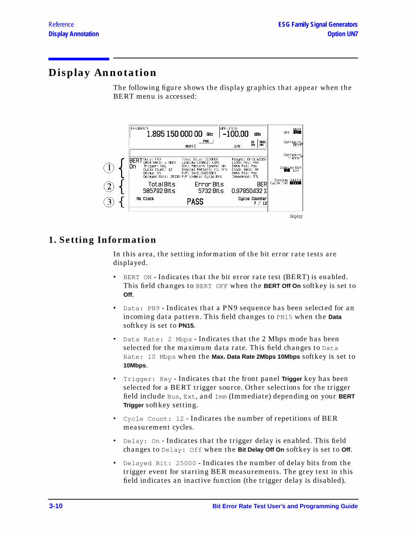
Display AnnotationThe following figure shows the display graphics that appear when theBERT menu is accessed:
1. Setting InformationIn this area, the setting information of the bit error rate tests aredisplayed.
• BERT ON - Indicates that the bit error rate test (BERT) is enabled.This field changes to BERT OFFwhen the BERT Off On softkey is set toOff .
• Data: PN9 - Indicates that a PN9 sequence has been selected for anincoming data pattern. This field changes to PN15 when the Datasoftkey is set to PN15.
• Data Rate: 2 Mbps - Indicates that the 2 Mbps mode has beenselected for the maximum data rate. This field changes to DataRate: 10 Mbps when the Max. Data Rate 2Mbps 10Mbps softkey is set to10Mbps .
• Trigger: Key - Indicates that the front panel Trigger key has beenselected for a BERT trigger source. Other selections for the triggerfield include Bus, Ext , and Imm (Immediate) depending on your BERTTrigger softkey setting.
• Cycle Count: 12 - Indicates the number of repetitions of BERmeasurement cycles.
• Delay: On - Indicates that the trigger delay is enabled. This fieldchanges to Delay: Off when the Bit Delay Off On softkey is set to Off .
• Delayed Bit: 25000 - Indicates the number of delay bits from thetrigger event for starting BER measurements. The grey text in thisfield indicates an inactive function (the trigger delay is disabled).
3-10 Bit Error Rate Test User’s and Programming Guide
ESG Family Signal Generators ReferenceOption UN7 Display Annotation
• Total Bits: 100000 - Indicates the total bit count to be measuredfor one measurement cycle.
• Display Update: Cont - Indicates that the continuous mode hasbeen selected for the display update mode. This field changes toDisplay Update: Cycle End when the Display Update Cycle End Contsoftkey is set to Cycle End .
• Spcl Pattern Ignore: On - Indicates that the special patternignore is enabled. This field changes to Spcl Pattern Ignore: Offwhen the Special Pattern Ignore Off On softkey is set to Off .
• Special Pattern: All 0’s - Indicates that the All 0’s data patternis selected for special pattern ignore function. This field changes toSpcl Pattern Ignore: All 1’s when the Special Pattern 0’s 1’ssoftkey is set to 1’s . The grey text in this field indicates an inactivefunction (the special patter ignore function is disabled).
• P/F: On(0.0100000) - Indicates that the pass/fail judgement isenabled and its threshold level is set to 0.0100000. This fieldchanges to P/F Off when the Pass/Fail Off On softkey is set to Off andthe number in parentheses changes to display whatever value is setfor the Pass/Fail Limit softkey.
• P/F Update: Cycle End - Indicates that the cycle end mode hasbeen selected for the pass/fail judgement update mode. This fieldchanges to Display Update: Fail Hold when Fail Hold is selected forthe Pass/Fail Update softkey. The text in grey indicates an inactivefunction (the pass/fail judgment is disabled).
• Resync: On(0.4000) - Indicates that the resynchronizing function isenabled and its threshold level is set to 0.4000. This field changes toResync: Off when the BERT Resync Off On softkey is set to Off and thenumber in parentheses changes to display whatever value is set forthe BERT Resync Limits softkey.
• Clock Pol: Pos - Indicates that the positive edge has been selectedfor the input polarity of the clock signal. This field changes to ClockPol: Neg when the Clock Polarity Neg Pos softkey is set to Neg.
• Data Pol: Pos - Indicates that the data signal is used as it is for thedata signal. This field changes to Data Pol: Neg when the DataPolarity Neg Pos softkey is set to Neg.
• Clock Gate: On - Indicates that the clock gate function is enabled.This field changes to Clock Gate: Off when the Clock Gate Off Onsoftkey is set to Off .
• Gate Pol: Pos - Indicates that the clock signal is valid when theclock gate signal is high. This field changes to Data Pol: Neg whenthe Data Polarity Neg Pos softkey is set to Neg. The grey text in this fieldindicates an inactive function (the clock gate function is disabled).
Bit Error Rate Test User’s and Programming Guide 3-11

Reference ESG Family Signal GeneratorsDisplay Annotation Option UN7
• Impedance: TTL - Indicates that the TTL has been selected for theinput termination mode. This field changes to Impedance: 75 Ohmwhen the Impedance 75 Ohm TTL softkey is set to 75 Ohm .
2. Measurement ResultsIn this area, the measurement results are displayed. When the DisplayUpdate Cycle End Cont softkey is set to Cycle End , the measurement resultis displayed only when the one measurement cycle has been completed.When the Display Update Cycle End Cont softkey is set to Cont , theintermediate measurement result is also displayed about every 200 msduring the measurement cycle.
NOTE You can select Cont only when the Max. Data Rate 2Mbps 10Mbps softkey isset to 2Mbps .
• Total Bits: 585792 Bits - Shows the total bit count.
• Error Bits: 5732 Bits - Shows the error bit count.
• BER: 0.97850432 % - Shows the bit error rate measurement result.The BER measurement result can be displayed in percent or in theexponential format.
3. Other InformationIn this area, the measurement cycle counter is displayed on the rightside. When the Pass/Fail Off On softkey is set to On, the result of thejudgement is displayed in the center. The measurement error statusmay be displayed on the left side.
• No Data - In this field, No Data or No Clock may be displayed. NoData is displayed when there has been no data change for more than200 clock signals. No Clock is displayed when there has been noclock input for more than 3 seconds.
Sync Loss may be displayed under the No Data annunciator whenthe synchronization is lost. (It is not shown in this example.)
• PASS - In this field, the pass/fail judgement result is displayed whenthe Pass/Fail Off On softkey is set to On.
• Cycle Counter: 7 / 12 - Indicates the current and totalmeasurement cycle counts.
3-12 Bit Error Rate Test User’s and Programming Guide
ESG Family Signal Generators ReferenceOption UN7 Rear Panel Overview
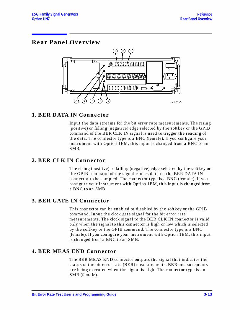
Rear Panel Overview
1. BER DATA IN ConnectorInput the data streams for the bit error rate measurements. The rising(positive) or falling (negative) edge selected by the softkey or the GPIBcommand of the BER CLK IN signal is used to trigger the reading ofthe data. The connector type is a BNC (female). If you configure yourinstrument with Option 1EM, this input is changed from a BNC to anSMB.
2. BER CLK IN ConnectorThe rising (positive) or falling (negative) edge selected by the softkey orthe GPIB command of the signal causes data on the BER DATA INconnector to be sampled. The connector type is a BNC (female). If youconfigure your instrument with Option 1EM, this input is changed froma BNC to an SMB.
3. BER GATE IN ConnectorThis connector can be enabled or disabled by the softkey or the GPIBcommand. Input the clock gate signal for the bit error ratemeasurements. The clock signal to the BER CLK IN connector is validonly when the signal to this connector is high or low which is selectedby the softkey or the GPIB command. The connector type is a BNC(female). If you configure your instrument with Option 1EM, this inputis changed from a BNC to an SMB.
4. BER MEAS END ConnectorThe BER MEAS END connector outputs the signal that indicates thestatus of the bit error rate (BER) measurements. BER measurementsare being executed when the signal is high. The connector type is anSMB (female).
Bit Error Rate Test User’s and Programming Guide 3-13
Reference ESG Family Signal GeneratorsRear Panel Overview Option UN7
5. BER TEST OUT ConnectorThe BER TEST OUT connector outputs the signal that indicates thetest result of the pass/fail judgment of the bit error rate measurements.The result is guaranteed at the falling edge of the signal of the MEASEND connector. The result is pass when the signal is low; the result isfail when the signal is high. The signal is also high when the pass/failjudgment is set to off. The connector type is an SMB (female).
6. BER ERR OUT ConnectorThe output of the BER ERR OUT connector is normally low. When themaximum data rate mode is set to 2 Mbps, the BER ERR OUTconnector outputs the pulse signals that indicate the number of theerror bits. One pulse whose width is about 80 ns indicates one error bit.Pulses for the error bits of one measurement cycle are not synchronizedwith the clock signal to the BER CLK IN connector, and are outputduring the signal of the BER MEAS END connector for themeasurement cycle is high. The connector type is an SMB (female).
7. BER NO DATA ConnectorThe BER NO DATA connector outputs the signal that indicates the nodata status. The no data status is reported when there has been noclock inputs for more than 3 seconds or there has been no data changefor more than 200 bits. This signal is valid only when the signal of theBER MEAS END connector is high. No data status is detected when thesignal is low. The connector type is an SMB (female).
8. BER SYNC LOSS ConnectorThe BER SYNC LOSS connector outputs the signal that indicates thesynchronization loss state. This signal is only valid when the signal ofthe BER MEAS END connector is high. Synchronization loss state isdetected when the signal is low. The connector type is an SMB (female).
3-14 Bit Error Rate Test User’s and Programming Guide
ESG Family Signal GeneratorsOption UN7
4 Operation
This section contains detailed information that will help you learn how to make bit errorrate tests using your Agilent Technologies ESG Family Signal Generator with OptionUN7.
Bit Error Rate Test User’s and Programming Guide 4-1

Operation ESG Family Signal GeneratorsTesting Signal Definitions Option UN7
Testing Signal DefinitionsThe following timing diagram shows the relationships between a trigger event and theoutput signals at the BER MEAS END and BER TEST OUT connectors.
Figure 4-1 Testing Signal Definitions
• T1 is a firmware handling time measured from a Trigger event to the rising edge of aBER MEAS END signal.
• T2 is a firmware handling time measured from the falling edge of a BER TEST OUTsignal to the falling edge of the BER MEAS END signal.
• T3 is a minimum requirement time measured from the falling edge of the BER MEASEND signal to the next trigger event. T3 should be greater than 0 second.
If a BER MEAS END signal stays high following a trigger event, the BER measurement isin progress and other trigger events are ignored. This state is stored in the status registerand can be queried.
The pulse output of the BER TEST OUT for the Nth-1 test result ends prior to the fallingedge of the BER MEAS END signal for the Nth measurement; so you can use this edge tostart latching the Nth test result.
4-2 Bit Error Rate Test User’s and Programming Guide
ESG Family Signal Generators OperationOption UN7 Functional Differences between Max. Data Rate 2 Mbps and 10 Mbps
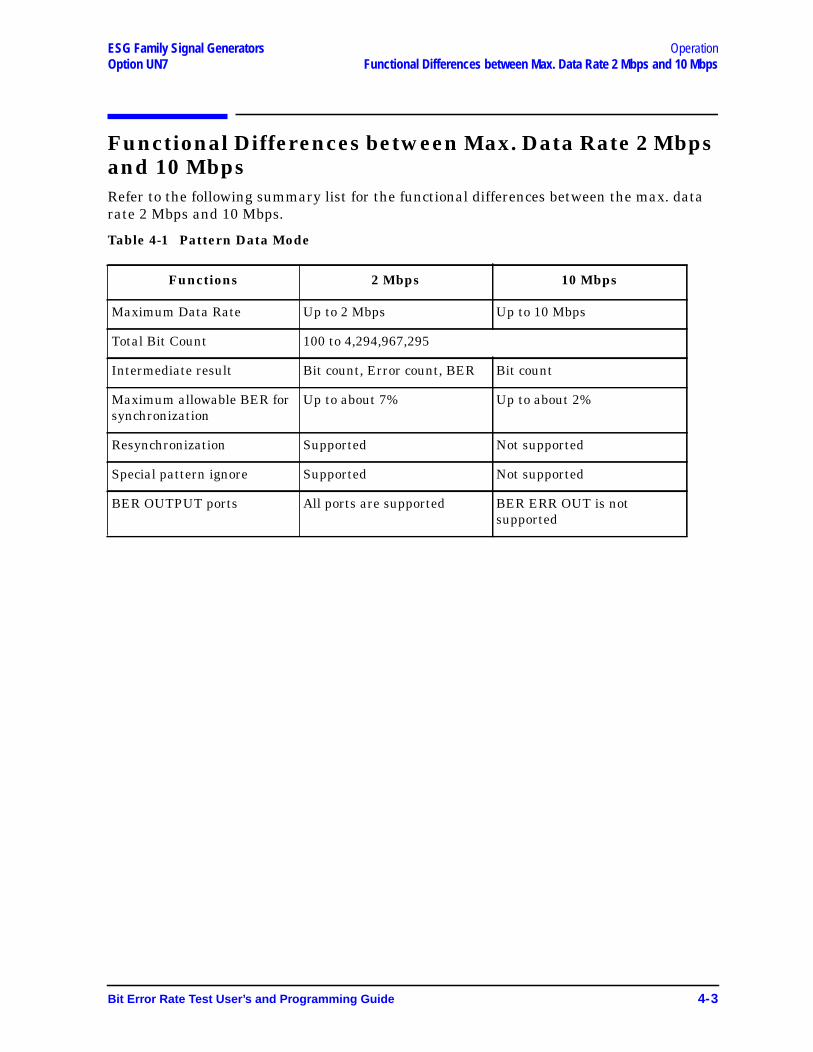
Functional Differences between Max. Data Rate 2 Mbpsand 10 MbpsRefer to the following summary list for the functional differences between the max. datarate 2 Mbps and 10 Mbps.
Table 4-1 Pattern Data Mode
Functions 2 Mbps 10 Mbps
Maximum Data Rate Up to 2 Mbps Up to 10 Mbps
Total Bit Count 100 to 4,294,967,295
Intermediate result Bit count, Error count, BER Bit count
Maximum allowable BER forsynchronization
Up to about 7% Up to about 2%
Resynchronization Supported Not supported
Special pattern ignore Supported Not supported
BER OUTPUT ports All ports are supported BER ERR OUT is notsupported
Bit Error Rate Test User’s and Programming Guide 4-3
Operation ESG Family Signal GeneratorsData Processing Option UN7
Data Processing
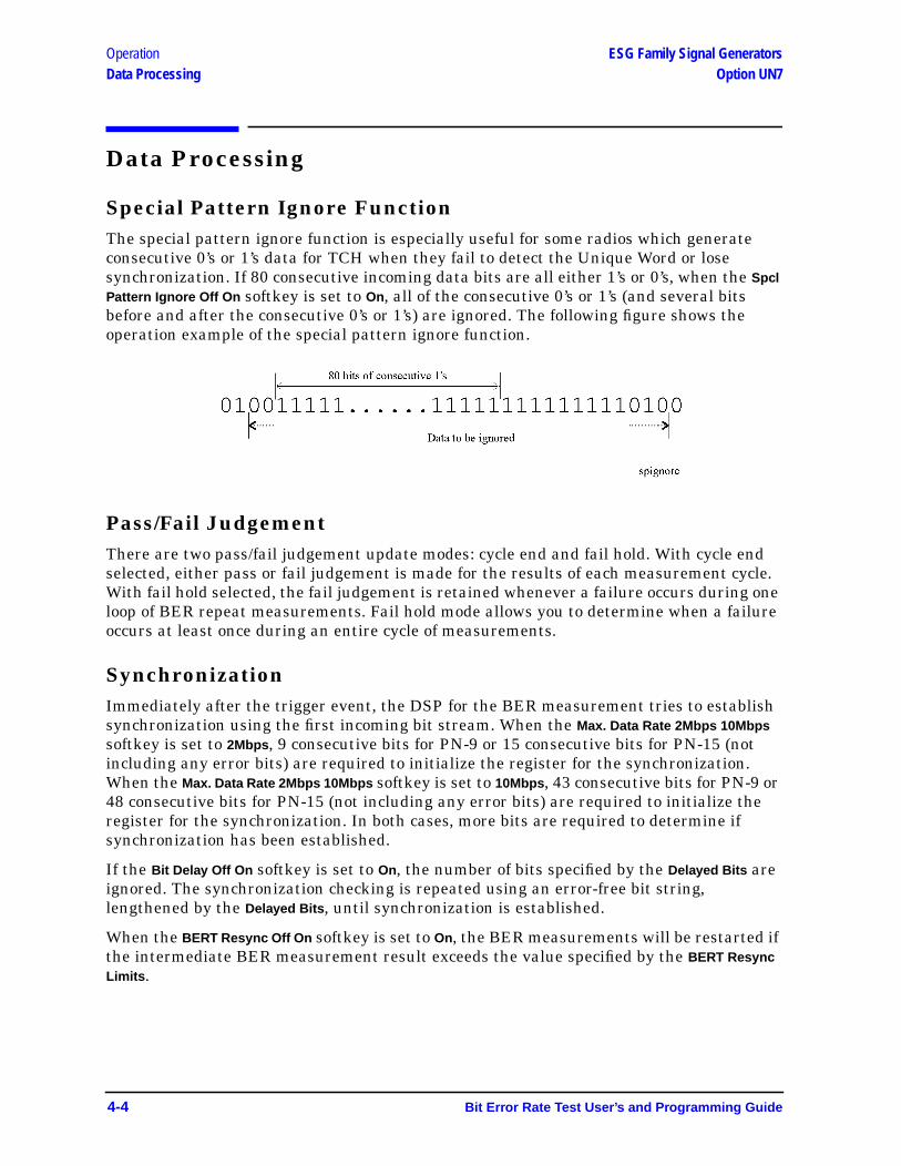
Special Pattern Ignore FunctionThe special pattern ignore function is especially useful for some radios which generateconsecutive 0’s or 1’s data for TCH when they fail to detect the Unique Word or losesynchronization. If 80 consecutive incoming data bits are all either 1’s or 0’s, when the SpclPattern Ignore Off On softkey is set to On, all of the consecutive 0’s or 1’s (and several bitsbefore and after the consecutive 0’s or 1’s) are ignored. The following figure shows theoperation example of the special pattern ignore function.
Pass/Fail JudgementThere are two pass/fail judgement update modes: cycle end and fail hold. With cycle endselected, either pass or fail judgement is made for the results of each measurement cycle.With fail hold selected, the fail judgement is retained whenever a failure occurs during oneloop of BER repeat measurements. Fail hold mode allows you to determine when a failureoccurs at least once during an entire cycle of measurements.
SynchronizationImmediately after the trigger event, the DSP for the BER measurement tries to establishsynchronization using the first incoming bit stream. When the Max. Data Rate 2Mbps 10Mbpssoftkey is set to 2Mbps , 9 consecutive bits for PN-9 or 15 consecutive bits for PN-15 (notincluding any error bits) are required to initialize the register for the synchronization.When the Max. Data Rate 2Mbps 10Mbps softkey is set to 10Mbps , 43 consecutive bits for PN-9 or48 consecutive bits for PN-15 (not including any error bits) are required to initialize theregister for the synchronization. In both cases, more bits are required to determine ifsynchronization has been established.
If the Bit Delay Off On softkey is set to On, the number of bits specified by the Delayed Bits areignored. The synchronization checking is repeated using an error-free bit string,lengthened by the Delayed Bits , until synchronization is established.
When the BERT Resync Off On softkey is set to On, the BER measurements will be restarted ifthe intermediate BER measurement result exceeds the value specified by the BERT ResyncLimits .
4-4 Bit Error Rate Test User’s and Programming Guide
ESG Family Signal Generators OperationOption UN7 Repeat Measurements
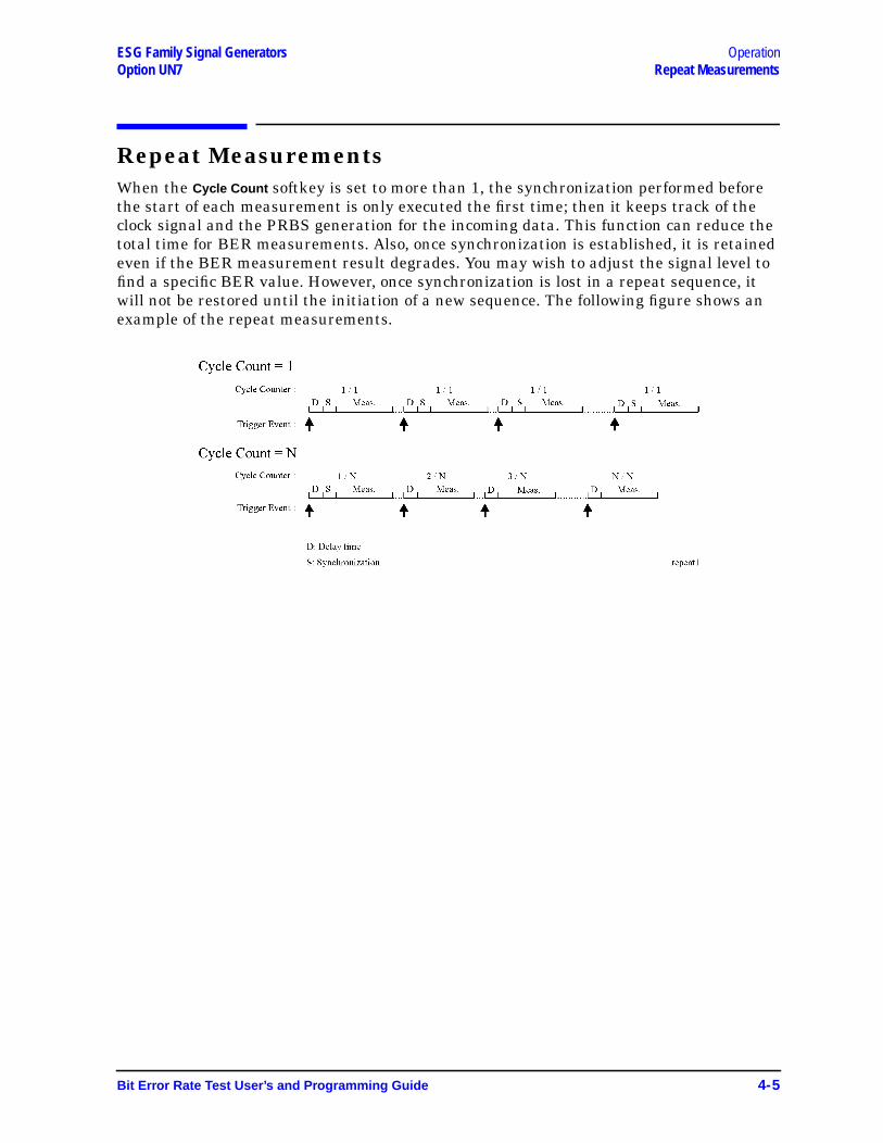
Repeat MeasurementsWhen the Cycle Count softkey is set to more than 1, the synchronization performed beforethe start of each measurement is only executed the first time; then it keeps track of theclock signal and the PRBS generation for the incoming data. This function can reduce thetotal time for BER measurements. Also, once synchronization is established, it is retainedeven if the BER measurement result degrades. You may wish to adjust the signal level tofind a specific BER value. However, once synchronization is lost in a repeat sequence, itwill not be restored until the initiation of a new sequence. The following figure shows anexample of the repeat measurements.
Bit Error Rate Test User’s and Programming Guide 4-5
Operation ESG Family Signal GeneratorsClock Gate Function Option UN7
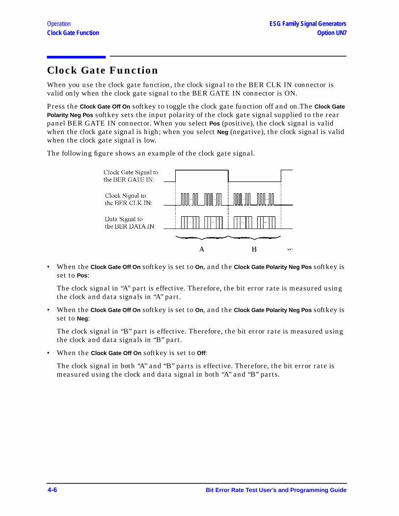
Clock Gate FunctionWhen you use the clock gate function, the clock signal to the BER CLK IN connector isvalid only when the clock gate signal to the BER GATE IN connector is ON.
Press the Clock Gate Off On softkey to toggle the clock gate function off and on.The Clock GatePolarity Neg Pos softkey sets the input polarity of the clock gate signal supplied to the rearpanel BER GATE IN connector. When you select Pos (positive), the clock signal is validwhen the clock gate signal is high; when you select Neg (negative), the clock signal is validwhen the clock gate signal is low.
The following figure shows an example of the clock gate signal.
• When the Clock Gate Off On softkey is set to On, and the Clock Gate Polarity Neg Pos softkey isset to Pos :
The clock signal in “A” part is effective. Therefore, the bit error rate is measured usingthe clock and data signals in “A” part.
• When the Clock Gate Off On softkey is set to On, and the Clock Gate Polarity Neg Pos softkey isset to Neg:
The clock signal in “B” part is effective. Therefore, the bit error rate is measured usingthe clock and data signals in “B” part.
• When the Clock Gate Off On softkey is set to Off :
The clock signal in both “A” and “B” parts is effective. Therefore, the bit error rate ismeasured using the clock and data signal in both “A” and “B” parts.
4-6 Bit Error Rate Test User’s and Programming Guide
ESG Family Signal GeneratorsOption UN7
5 Remote Programming
This chapter provides information about the BERT subsystem SCPI commands inalphabetical order. The descriptions include syntax requirements, ranges, restrictions,query responses, and status after *RST.
Bit Error Rate Test User’s and Programming Guide 5-1

Remote Programming ESG Family Signal Generators:CALCulate Subsystem SCPI Command Reference Option UN7
:CALCulate Subsystem SCPI Command ReferenceThe Calculate subsystem SCPI commands are used to set the controls and parametersassociated with the display mode and the pass/fail judgement mode.
BER Display Mode:CALCulate:BERT:DISPlay:MODE PERCent|SCIentific:CALCulate:BERT:DISPlay:MODE?
This command selects the display mode for bit error rate measurement results. Thechoices are PERCent and SCIentific . When you select PERCent, BER measurement resultsare displayed in %. When you select SCIentific , BER measurement results are displayedin the following format: n.nnnnnE-mm (where n.nnnnn is a floating point part and E-mmis a power exponent part).
*RST value: Percent.
BER Display Update Mode:CALCulate:BERT:DISPlay:UPDate CEND|CONT:CALCulate:BERT:DISPlay:UPDate?
This command selects the display update mode during BER measurements. The choicesare CEND (Cycle End) and CONT (Continuous). When you select CEND, the previous BERmeasurement result is displayed during the current measuring period. When you selectCONT, the display shows its real-time intermediate results during each BER measurement.
*RST value: Cycle End.
BER Pass/Fail Judgement Mode:CALCulate:BERT:COMParator:MODE CEND|FHOLd:CALCulate:BERT:COMParator:MODE?
This command selects the pass/fail judgement mode of the comparator function. Thechoices are CEND (Cycle End) and FHOLd (Fail Hold). When you select CEND, each BERmeasurement result is compared with the Pass/Fail Limit value and judged to make apass/fail test. When you select FHOLd, only one fail judgement is made once a fail has beenfound during that BER measurement loop. For automated tests, use the output signal fromthe rear panel BER TEST OUT port.
*RST value: Cycle End.
5-2 Bit Error Rate Test User’s and Programming Guide
ESG Family Signal Generators Remote ProgrammingOption UN7 :CALCulate Subsystem SCPI Command Reference
BER Pass/Fail Limits:CALCulate:BERT:COMParator:THReshold <num>:CALCulate:BERT:COMParator:THReshold?
This command specifies the threshold value for the pass/fail judgement function. Thiscommand is valid only while the BER pass/fail state command is ON (1). The range of thevariable is from 0 to 1.
*RST value: 0.5.
BER Pass/Fail State:CALCulate:BERT:COMParator[:STATe] ON|OFF|1|0:CALCulate:BERT:COMParator[:STATe]?
This command enables and disables the pass/fail judgement function. The choices are ON(1) and OFF (0) . For automated tests, use the output signal from the rear panel BERTEST OUT port.
*RST value: Off.
Bit Error Rate Test User’s and Programming Guide 5-3
Remote Programming ESG Family Signal Generators:DATA Subsystem SCPI Command Reference Option UN7
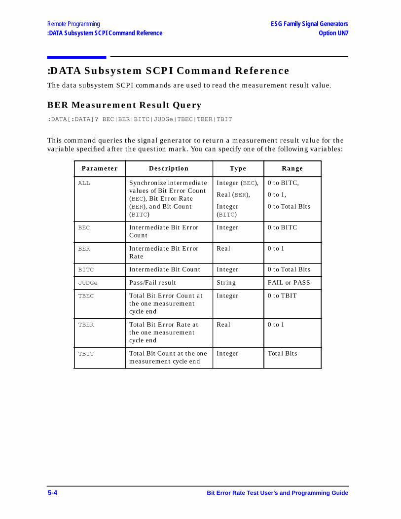
:DATA Subsystem SCPI Command ReferenceThe data subsystem SCPI commands are used to read the measurement result value.
BER Measurement Result Query:DATA[:DATA]? BEC|BER|BITC|JUDGe|TBEC|TBER|TBIT
This command queries the signal generator to return a measurement result value for thevariable specified after the question mark. You can specify one of the following variables:
Parameter Description Type Range
ALL Synchronize intermediatevalues of Bit Error Count(BEC), Bit Error Rate(BER), and Bit Count(BITC )
Integer (BEC),
Real (BER),
Integer(BITC )
0 to BITC,
0 to 1,
0 to Total Bits
BEC Intermediate Bit ErrorCount
Integer 0 to BITC
BER Intermediate Bit ErrorRate
Real 0 to 1
BITC Intermediate Bit Count Integer 0 to Total Bits
JUDGe Pass/Fail result String FAIL or PASS
TBEC Total Bit Error Count atthe one measurementcycle end
Integer 0 to TBIT
TBER Total Bit Error Rate atthe one measurementcycle end
Real 0 to 1
TBIT Total Bit Count at the onemeasurement cycle end
Integer Total Bits
5-4 Bit Error Rate Test User’s and Programming Guide

ESG Family Signal Generators Remote ProgrammingOption UN7 :INPut Subsystem SCPI Command Reference
:INPut Subsystem SCPI Command ReferenceThe input subsystem SCPI commands are used to set the controls and the parametersassociated with the input connectors for the bit error rate tests.
BER Clock Gate Polarity:INPut:BERT:CGATe:POLarity POSitive|NEGative:INPut:BERT:CGATe:POLarity?
This command selects the clock gate polarity. The choices are POSitive and NEGative .This clock gate signal is supplied to the rear panel BER GATE IN port. This command isvalid only while the BER clock gate state is ON (1).
*RST value: Positive.
BER Clock Gate State:INPut:BERT:CGATe[:STATe] ON|OFF|1|0:INPut:BERT:CGATe[:STATe]?
This command enables and disables the clock gate function. The choices are ON (1) andOFF (0) .
*RST value: Off.
BER Clock Polarity:INPut:BERT:CLOCk:POLarity POSitive|NEGative:INPut:BERT:CLOCk:POLarity?
This command selects the clock polarity according to the clock signal supplied to the rearpanel BER CLK IN port. The choices are POSitive and NEGative .
*RST value: Positive.
BER Data Polarity:INPut:BERT:DATA:POLarity POSitive|NEGative:INPut:BERT:DATA:POLarity?
This command selects the polarity of the data signal. The choices are POSitive andNEGative .
*RST value: Positive.
Bit Error Rate Test User’s and Programming Guide 5-5

Remote Programming ESG Family Signal Generators:INPut Subsystem SCPI Command Reference Option UN7
BER Input Impedance:INPut:BERT:IMPedance OHM_75|TTL:INPut:BERT:IMPedance?
This command selects the input impedance according to the input signals supplied to therear panel BER DATA IN, BER CLK IN, and BER GATE IN ports. The choices are OHM_75(75 Ω) and TTL.
*RST value: TTL.
5-6 Bit Error Rate Test User’s and Programming Guide

ESG Family Signal Generators Remote ProgrammingOption UN7 :SENSe Subsystem SCPI Command Reference
:SENSe Subsystem SCPI Command ReferenceThe sense subsystem SCPI commands are used to set the controls and parametersassociated with the bit error rate measurements.
BER Cycle Count:SENSe:BERT:TRIGger:COUNt <num>:SENSe:BERT:TRIGger:COUNt?
This command specifies the repeat times of BER measurements. The range of the variableis from 1 to 65,535.
*RST value: 1.
BER Data Pattern:SENSe:BERT:PRBS[:DATA] PN9|PN15:SENSe:BERT:PRBS[:DATA]?
This command selects the data pattern for the incoming data bit stream to make BERmeasurements. The choices are PN9 and PN15.
*RST value: PN9.
BER Maximum Data Rate:SENSe:BERT:PRBS:MDRate BPS_2M|BPS_10M:SENSe:BERT:PRBS:MDRate?
This command selects the maximum data rate mode. The choices are BPS_2M(2 Mbps) andBPS_10M (10 Mbps). When you select 2 Mbps, all BERT functions are available forconfiguration. When you select 10 Mbps, the pass/fail judgement and special patternignore functions are unavailable.
*RST value: 2 Mbps.
BER Resync Limits:SENSe:BERT:RSYNc:THReshold <num>:SENSe:BERT:RSYNc:THReshold?
This command specifies the threshold level for the resynchronizing function. The range ofthe variable is from 0.05 to 0.40. This function is valid only when BERT resynchronizationstate is set to On.
*RST value: 0.40.
Bit Error Rate Test User’s and Programming Guide 5-7

Remote Programming ESG Family Signal Generators:SENSe Subsystem SCPI Command Reference Option UN7
BER Resynchronization State:SENSe:BERT:RSYNc[:STATe] ON|OFF|1|0:SENSe:BERT:RSYNc[:STATe]?
This command enables and disables the resynchronization function. The choices are ON(1) and OFF (0) . This function is valid only when the maximum data rate is set to 2 Mbps.
*RST value: On.
BER Special Pattern Ignore Data:SENSe:BERT:PRBS:FUNCtion:SPIGnore:DATA ALL_0|ALL_1:SENSe:BERT:PRBS:FUNCtion:SPIGnore:DATA?
This command selects the bit parameter of the special pattern ignore function. The choicesare ALL_0 (All 0’s) and ALL_1 (All 1’s). This command is valid only when Special PatternIgnore state is already set to On.
*RST value: All 0’s.
BER Special Pattern Ignore State:SENSe:BERT:PRBS:FUNCtion:SPIGnore[:STATe] ON|OFF|1|0:SENSe:BERT:PRBS:FUNCtion:SPIGnore[:STATe]?
This command enables and disables the operating state of the special pattern ignorefunction. The choices are ON (1) and OFF (0) . This function detects more than 80 bits of0's or 1's in the incoming bit stream and ignores these bits when making BERmeasurements. This command is valid only when the maximum data rate is set to 2 Mbps.
*RST value: Off.
BER Total Bits:SENSe:BERT:TBITs <num>:SENSe:BERT:TBITs?
This command specifies the total bit count to be measured. The range of the variable isfrom 100 to 4,294,967,295.
*RST value: 10,000.
5-8 Bit Error Rate Test User’s and Programming Guide

ESG Family Signal Generators Remote ProgrammingOption UN7 :SENSe Subsystem SCPI Command Reference
BER Trigger Bit Delay:SENSe:BERT:TRIGger[:SOURce]:BDELay <num>:SENSe:BERT:TRIGger[:SOURce]:BDELay?
This command specifies the number of delay bits for the trigger delay. The range of thevariable is from 0 to 65,535. This function is valid only when the trigger bit delay state isset to On.
*RST value: 0.
BER Trigger Bit Delay State:SENSe:BERT:TRIGger:BDELay:STATe ON|OFF|1|0:SENSe:BERT:TRIGger:BDELay:STATe?
This command enables and disables the trigger bit delay function. The choices are ON (1)and OFF (0) .
*RST value: Off.
BER Trigger Source:SENSe:BERT:TRIGger[:SOURce] BUS|EXTernal|IMMediate|KEY:SENSe:BERT:TRIGger[:SOURce]?
This command selects the triggering type for starting BER measurements. The choices areBUS (trigger with a *TRG GPIB command), EXTernal (trigger with an external signalsupplied to the rear panel TRIGGER IN connector), IMMediate , and KEY(trigger using thefront panel Trigger key).
*RST value: Key.
BERT State:SENSe:BERT:STATe ON|OFF|1|0:SENSe:BERT:STATe?
This command enables and disables the BER measurement function. The choices are ON(1) or OFF (0).
*RST value: Off.
Bit Error Rate Test User’s and Programming Guide 5-9
Remote Programming ESG Family Signal Generators:STATus Subsystem SCPI Command Reference Option UN7
:STATus Subsystem SCPI Command ReferenceThe IEEE status subsystem is used to set the controls and the parameters associated withstatus conditions within the signal generator. For more information on the status registergroup and the data questionable BERT status group, refer to Chapter 1,“Preparing for Use,” of the programming guide.
Status Preset:STATus:PRESet
This command presets all transition filters, enable registers, and all error/event queueenable registers.
Data Questionable BERT Status Group Condition RegisterQuery:STATus:QUEStionable:BERT:CONDition?
This command returns the decimal value of the sum of the bits in the Data QuestionableBERT Condition Register. For example, if no clock signal has been input for more thanthree seconds during the bit error rate measurements (bit 0), then a value of 1 is returned.Note that the data in this register is continuously updated and reflects the currentconditions.
Data Questionable BERT Status Group Enable:STATus:QUEStionable:BERT:ENAble <num>
This command determines which bits in the Data Questionable BERT Status Group EventRegister will set the Data Questionable BERT Summary bit (bit 12) in the DataQuestionable Status Group Condition Register. The variable <num> is the sum of thedecimal values of the bits you want to enable.
Data Questionable BERT Status Group Event Register Query:STATus:QUEStionable:BERT[:EVENt]?
This command returns the decimal value of the sum of the bits in the Data QuestionableBERT Event Register. For example, if no clock signal for the bit error rate tests has beeninput for more than three seconds (bit 0), then a 1 is returned. Note that the registerrequires that the equivalent PTR or NTR filters be set before a condition register bit canset a bit in the Event register. Note also that the data in this register is latched until it isqueried. Once queried, the data is cleared.
5-10 Bit Error Rate Test User’s and Programming Guide
ESG Family Signal Generators Remote ProgrammingOption UN7 :STATus Subsystem SCPI Command Reference
Data Questionable BERT Status Negative Transition FilterRegister Enable:STATus:QUEStionable:BERT:NTRansition <num>
This command determines which bits in the Data Questionable BERT Status GroupCondition Register will set the corresponding bit in the Data Questionable BERT StatusGroup Event Register when that bit has a negative transition (1 to 0). The variable <num>is the sum of the decimal values of the bits that you want to enable.
Data Questionable BERT Status Positive Transition FilterRegister Enable:STATus:QUEStionable:BERT:PTRansition <num>
This command determines which bits in the Data Questionable BERT Status GroupCondition Register will set the corresponding bit in the Data Questionable BERT StatusGroup Event Register when that bit has a positive transition (0 to 1). The variable <num> isthe sum of the decimal values of the bits that you want to enable.
Bit Error Rate Test User’s and Programming Guide 5-11
Remote Programming ESG Family Signal Generators:TRIGger Subsystem SCPI Command Reference Option UN7
:TRIGger Subsystem SCPI Command ReferenceThe trigger subsystem is used to set the controls and parameters associated withtriggering a BER measurement.
Abort:ABORt
There is no query for this command.
This command causes the sweep in progress to abort, then resets the sweep. Thiscommand can also cause the BER measurement in progress to abort, and then set the BERmeasurement state to Off. The pending operation flag (affecting *OPC, *WAI , and *OPC?)will undergo a transition once the sweep or BER measurement has been reset.
5-12 Bit Error Rate Test User’s and Programming Guide
ESG Family Signal GeneratorsOption UN7
6 Programming CommandCross-Reference
This chapter lists BERT softkeys and their corresponding SCPI programming commands.
Bit Error Rate Test User’s and Programming Guide 6-1

Programming Command Cross-Reference ESG Family Signal GeneratorsOption UN7
Mode - BERT Softkeys
Key SCPI Command
BERT Off On :SENSe:BERT:STATe ON|OFF|1|0
:SENSe:BERT:STATe?
BERT Resync Off On :SENSe:BERT:RSYNc[:STATe] ON|OFF|1|0
:SENSe:BERT:RSYNc[:STATe]?
BERT Trigger :SENSe:BERT:TRIGger[:SOURce] IMMediate|KEY|BUS|EXTernal
:SENSe:BERT:TRIGger[:SOURce]?
Bit Delay Off On :SENSe:BERT:TRIGger:BDELay:STATe ON|OFF|1|0
:SENSe:BERT:TRIGger:BDELay:STATe?
Bus :SENSe:BERT:TRIGger[:SOURce] BUS
:SENSe:BERT:TRIGger[:SOURce]?
Clock Gate Off On :INPut:BERT:CGATe[:STATe] ON|OFF|1|0
:INPut:BERT:CGATe[:STATe]?
Clock Gate Polarity Neg Pos :INPut:BERT:CGATe:POLarity NEGative|POSitive
:INPut:BERT:CGATe:POLarity?
Clock Polarity Neg Pos :INPut:BERT:CLOCk:POLarity NEGative|POSitive
:INPut:BERT:CLOCk:POLarity?
Cycle Count :SENSe:BERT:TRIGger:COUNt <num>
:SENSe:BERT:TRIGger:COUNt?
Cycle End :CALCulate:BERT:COMParator:MODE CEND
:CALCulate:BERT:COMParator:MODE?
Data :SENSe:BERT:PRBS[:DATA] PN9|PN15
:SENSe:BERT:PRBS[:DATA]?
Data Polarity Neg Pos :INPut:BERT:DATA:POLarity NEGative|POSitive
:INPut:BERT:DATA:POLarity?
Delayed Bits :SENSe:BERT:TRIGger:BDELay <num>
:SENSe:BERT:TRIGger:BDELay?
Display BER % Exp :CALCulate:BERT:DISPlay:MODE PERCent|SCIentific
:CALCulate:BERT:DISPlay:MODE?
Display Update Cycle End Cont :CALCulate:BERT:DISPlay:UPDate CEND|CONT
:CALCulate:BERT:DISPlay:UPDate?
6-2 Bit Error Rate Test User’s and Programming Guide
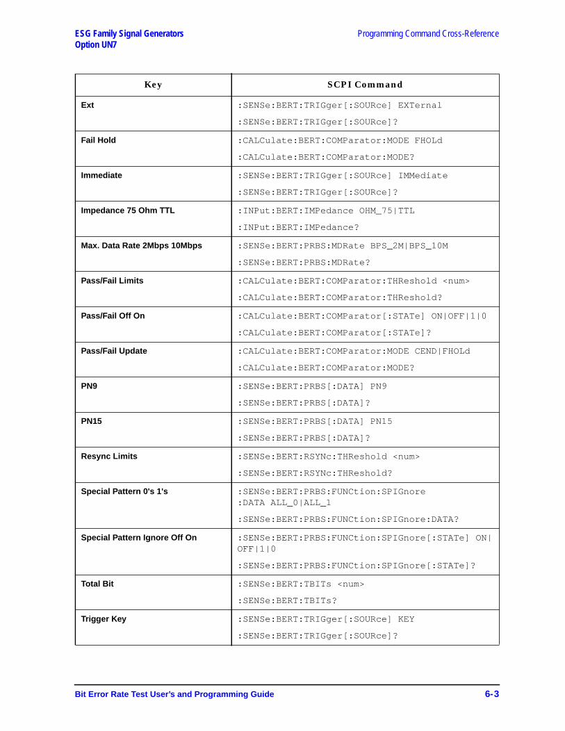
ESG Family Signal Generators Programming Command Cross-ReferenceOption UN7
Ext :SENSe:BERT:TRIGger[:SOURce] EXTernal
:SENSe:BERT:TRIGger[:SOURce]?
Fail Hold :CALCulate:BERT:COMParator:MODE FHOLd
:CALCulate:BERT:COMParator:MODE?
Immediate :SENSe:BERT:TRIGger[:SOURce] IMMediate
:SENSe:BERT:TRIGger[:SOURce]?
Impedance 75 Ohm TTL :INPut:BERT:IMPedance OHM_75|TTL
:INPut:BERT:IMPedance?
Max. Data Rate 2Mbps 10Mbps :SENSe:BERT:PRBS:MDRate BPS_2M|BPS_10M
:SENSe:BERT:PRBS:MDRate?
Pass/Fail Limits :CALCulate:BERT:COMParator:THReshold <num>
:CALCulate:BERT:COMParator:THReshold?
Pass/Fail Off On :CALCulate:BERT:COMParator[:STATe] ON|OFF|1|0
:CALCulate:BERT:COMParator[:STATe]?
Pass/Fail Update :CALCulate:BERT:COMParator:MODE CEND|FHOLd
:CALCulate:BERT:COMParator:MODE?
PN9 :SENSe:BERT:PRBS[:DATA] PN9
:SENSe:BERT:PRBS[:DATA]?
PN15 :SENSe:BERT:PRBS[:DATA] PN15
:SENSe:BERT:PRBS[:DATA]?
Resync Limits :SENSe:BERT:RSYNc:THReshold <num>
:SENSe:BERT:RSYNc:THReshold?
Special Pattern 0's 1's :SENSe:BERT:PRBS:FUNCtion:SPIGnore:DATA ALL_0|ALL_1
:SENSe:BERT:PRBS:FUNCtion:SPIGnore:DATA?
Special Pattern Ignore Off On :SENSe:BERT:PRBS:FUNCtion:SPIGnore[:STATe] ON|OFF|1|0
:SENSe:BERT:PRBS:FUNCtion:SPIGnore[:STATe]?
Total Bit :SENSe:BERT:TBITs <num>
:SENSe:BERT:TBITs?
Trigger Key :SENSe:BERT:TRIGger[:SOURce] KEY
:SENSe:BERT:TRIGger[:SOURce]?
Key SCPI Command
Bit Error Rate Test User’s and Programming Guide 6-3
Programming Command Cross-Reference ESG Family Signal GeneratorsOption UN7
6-4 Bit Error Rate Test User’s and Programming Guide
ESG Family Signal GeneratorsOption UN7
7 Programming Examples
The following section includes a programming example to help you understand how tobuild automated tests using the bit error rate test.
Bit Error Rate Test User’s and Programming Guide 7-1

Programming Examples ESG Family Signal GeneratorsTesting Bit Error Rate on a PHS radio Option UN7
Testing Bit Error Rate on a PHS radioIn this example, the signal generator is configured to the initial settings of a PHS π/4DQPSK Modulation Sensitivity Bit Error test. The carrier frequency is set to 1.89515 GHzat -100 dBm. PRBS data type is PN9 with the max. data rate of 2 Mbps. BERT Total Bit isset to 10,000. BERT Trigger is set to Bus.
CLEAR and RESET the controller, type the following commands and RUN the program.
10 !*******************************************************20 !30 ! PROGRAM NAME: BERT.BAS Rev. A.01.0040 !50 ! PROGRAM DESCRIPTION: In this example, the signal generator is60 ! configured to the initial settings of a PHS Pi/4 DQPSK70 ! modulation sensitivity bit error test. The carrier is a80 ! frequency of 1.89515 GHz at -100 dBm. PRBS data type is PN9 with90 ! the max. data rate of 2 Mbps. BERT Total Bit is set to 10,000.100 ! BERT Trigger is set to Bus.110 !120 ! CLEAR and RESET the controller, and type the following commands and RUN
130 ! the program:140 !150 !*********************************************************
160 !170 Sig_gen=719180 LOCAL Sig_gen190 CLEAR Sig_gen200 CLEAR SCREEN210 OUTPUT Sig_gen;"*RST"220 OUTPUT Sig_gen;"*CLS"230 ! *********************************************240 OUTPUT Sig_gen;"RAD:PHS:FCH 1"250 OUTPUT Sig_gen;"RAD:PHS:BURS:STAT ON"260 OUTPUT Sig_gen;"RAD:PHS:DLIN:SLOT1:TYP TCH"270 OUTPUT Sig_gen;"RAD:PHS:DLIN:SLOT1:STAT ON"280 OUTPUT Sig_gen;"RAD:PHS:STAT ON"290 OUTPUT Sig_gen;"POW -100 dBm"300 OUTPUT Sig_gen;"OUTP ON"310 ! *********************************************320 INPUT "Set the UUT to the RX mode, then press [Enter].",Dummy$330 ! *********************************************340 OUTPUT Sig_gen;"SENS:BERT:PRBS PN9"350 OUTPUT Sig_gen;"SENS:BERT:PRBS:MDR BPS_2M"
360 OUTPUT Sig_gen;"SENS:BERT:TBIT 10000"370 OUTPUT Sig_gen;"SENS:BERT:STAT ON"380 OUTPUT Sig_gen;"SENS:BERT:TRIG BUS"390 OUTPUT Sig_gen;"*TRG"400 ! *********************************************410 WAIT 0.2420 REPEAT430 OUTPUT Sig_gen;"STAT:OPER:COND?"440 ENTER Sig_gen;Bert_stat450 UNTIL BIT(Bert_stat,4)=0460 ! *********************************************470 OUTPUT Sig_gen;"DATA? TBER"480 ENTER Sig_gen;A490 PRINT "BER:",A500 ! *********************************************510 LOCAL Sig_gen
7-2 Bit Error Rate Test User’s and Programming Guide
ESG Family Signal Generators Programming ExamplesOption UN7 Testing Bit Error Rate on a PHS radio
520 DISP "Press RUN to start again."530 END
Program Comments
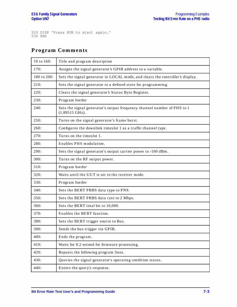
10 to 160: Title and program description
170: Assigns the signal generator’s GPIB address to a variable.
180 to 200: Sets the signal generator in LOCAL mode, and clears the controller’s display.
210: Sets the signal generator to a defined state for programming.
220: Clears the signal generator’s Status Byte Register.
230: Program border
240: Sets the signal generator's output frequency channel number of PHS to 1(1.89515 GHz).
250: Turns on the signal generator's frame burst.
260: Configures the downlink timeslot 1 as a traffic channel type.
270: Turns on the timeslot 1.
280: Enables PHS modulation.
290: Sets the signal generator's output carrier power to -100 dBm.
300: Turns on the RF output power.
310: Program border
320: Waits until the UUT is set to the receiver mode.
330: Program border
340: Sets the BERT PRBS data type to PN9.
350: Sets the BERT PRBS data rate to 2 Mbps.
360: Sets the BERT total bit to 10,000.
370: Enables the BERT function.
380: Sets the BERT trigger source to Bus.
390: Sends the bus trigger via GPIB.
400: Ends the program.
410: Waits for 0.2 second for firmware processing.
420: Repeats the following program lines.
430: Queries the signal generator's operating condition status.
440: Enters the query's response.
Bit Error Rate Test User’s and Programming Guide 7-3
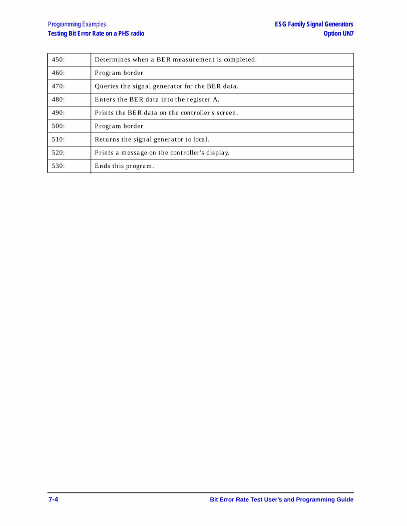
Programming Examples ESG Family Signal GeneratorsTesting Bit Error Rate on a PHS radio Option UN7
450: Determines when a BER measurement is completed.
460: Program border
470: Queries the signal generator for the BER data.
480: Enters the BER data into the register A.
490: Prints the BER data on the controller's screen.
500: Program border
510: Returns the signal generator to local.
520: Prints a message on the controller's display.
530: Ends this program.
7-4 Bit Error Rate Test User’s and Programming Guide
Index
BBER, 1-2
clock gatepolarity, 5-5state, 5-5
clock polarity, 5-5connectors
BER CLK IN, 3-13BER DATA IN, 3-13BER ERR OUT, 3-14BER GATE IN, 3-13BER MEAS END, 3-13BER NO DATA, 3-14BER SYNC LOSS, 3-14BER TEST OUT, 3-14
cycle count, 5-7data pattern, 5-7data polarity, 5-5display mode, 5-2display update mode, 5-2input impedance, 5-6maximum data rate, 5-7measurement result query, 5-4pass/fail
judgement mode, 5-2limits, 5-3state, 5-3
resync limits, 5-7resynchronization state, 5-8special pattern ignore data, 5-8special pattern ignore state, 5-8total bits, 5-8trigger
bit delay, 5-9bit delay state, 5-9source, 5-9
BERT, 1-1BERT softkeys
BERT, 3-2BERT Off On, 3-2BERT Resync Off On, 3-3BERT Trigger, 3-3
BERT State, 5-9bit error rate test
setting up, 2-2bit error rate. See BERBus softkey, 3-3
CCALCulate subsystem, 5-2
BER display mode, 5-2BER display update mode, 5-2BER pass/fail judgement mode, 5-2BER pass/fail limits, 5-3BER pass/fail state, 5-3
clock gate, 4-6Clock Gate Off On softkey, 3-3
Clock Gate Polarity Neg Pos softkey, 3-3Clock Polarity Neg Pos softkey, 3-4Configure BERT softkey, 3-4Configure Trigger softkey, 3-4connectors
BER CLK IN, 3-13BER DATA IN, 3-13BER ERR OUT, 3-14BER GATE IN, 3-13BER MEAS END, 3-13BER NO DATA, 3-14BER SYNC LOSS, 3-14BER TEST OUT, 3-14
Cycle Count softkey, 3-4Cycle End softkey, 3-5
DData Polarity Neg Pos softkey, 3-5data processing, 4-4
pass/fail judgment, 4-4synchronization, 4-4
data questionable BERT status group conditionregister query SCPI command, 5-10
data questionable BERT status group enable, 5-10data questionable BERT status group event register
query, 5-10data questionable BERT status NTR filter enable,
5-11data questionable BERT status PTR filter enable,
5-11Data softkey, 3-5DATA subsystem, 5-4
BER measurement result query, 5-4Delayed Bits softkey, 3-5display annotation, 3-10Display BER % Exp softkey, 3-6Display Update Cycle End Cont softkey, 3-6
Eexample program
testing bit error rate on a PHS radio, 7-2External softkey, 3-6, 3-9
FFail Hold softkey, 3-6functional differences between max. data rate 2 Mbps
and 10 Mbps, 4-3
Hhardkeys
Mode, 3-2
IImmediate softkey, 3-6Impedance 75 Ohm TTL softkey, 3-7
Index I-1
Index
INPut subsystem, 5-5BER clock gate polarity, 5-5BER clock gate state, 5-5BER clock polarity, 5-5BER data polarity, 5-5BER input impedance, 5-6
MMax. Data Rate 2Mbps 10Mbps softkey, 3-7Mode hardkey, 3-2
Ppass/fail judgment, 4-4Pass/Fail softkeys
Pass/Fail Limits, 3-7Pass/Fail Off On, 3-7Pass/Fail Update, 3-8
PN15 softkey, 3-8PN9 softkey, 3-8PRBS data rate
set, 7-3PRBS data type
set, 7-3
Rrepeat measurements, 4-5Resync Limits softkey, 3-8
SSCPI commands
BERT State, 5-9data questionable BERT status group condition
register query, 5-10data questionable BERT status group enable, 5-10data questionable BERT status group event register
query, 5-10data questionable BERT status NTR filter enable,
5-11data questionable BERT status PTR filter enable,
5-11status preset, 5-10
SENSe subsystem, 5-7BER
cycle count, 5-7data pattern, 5-7maximum data rate, 5-7resync limits, 5-7resynchronization state, 5-8special pattern ignore data, 5-8special pattern ignore state, 5-8total bits, 5-8trigger bit delay, 5-9trigger bit delay state, 5-9trigger source, 5-9
BERT State, 5-9set BERT PRBS data rate, 7-3
set BERT PRBS data type, 7-3set BERT total bit, 7-3set BERT trigger source, 7-3setting up
bit error rate test, 2-2softkey reference, 3-2Special Pattern 0’s 1’s softkey, 3-9special pattern ignore function, 4-4status preset, 5-10STATus subsystem, 5-10
data questionable BERT status group conditionregister query, 5-10
data questionable BERT status group enable, 5-10data questionable BERT status group event register
query, 5-10data questionable BERT status NTR filter enable,
5-11data questionable BERT status PTR filter enable,
5-11status preset, 5-10
synchronization, 4-4
Ttesting signal definitions, 4-2total bit
set, 7-3Total Bits softkey, 3-9trigger source
set, 7-3TRIGger subsystem, 5-12
abort SCPI command, 5-12
I-2 Index